Elbit Systems Land and C4I Tadiran MICOM-PF25W Licensed Non-Broadcast Station Transmitter User Manual micomPathFinder omE RevC fp

Elbit Systems Land and C4I - Tadiran Ltd. Licensed Non-Broadcast Station Transmitter micomPathFinder omE RevC fp

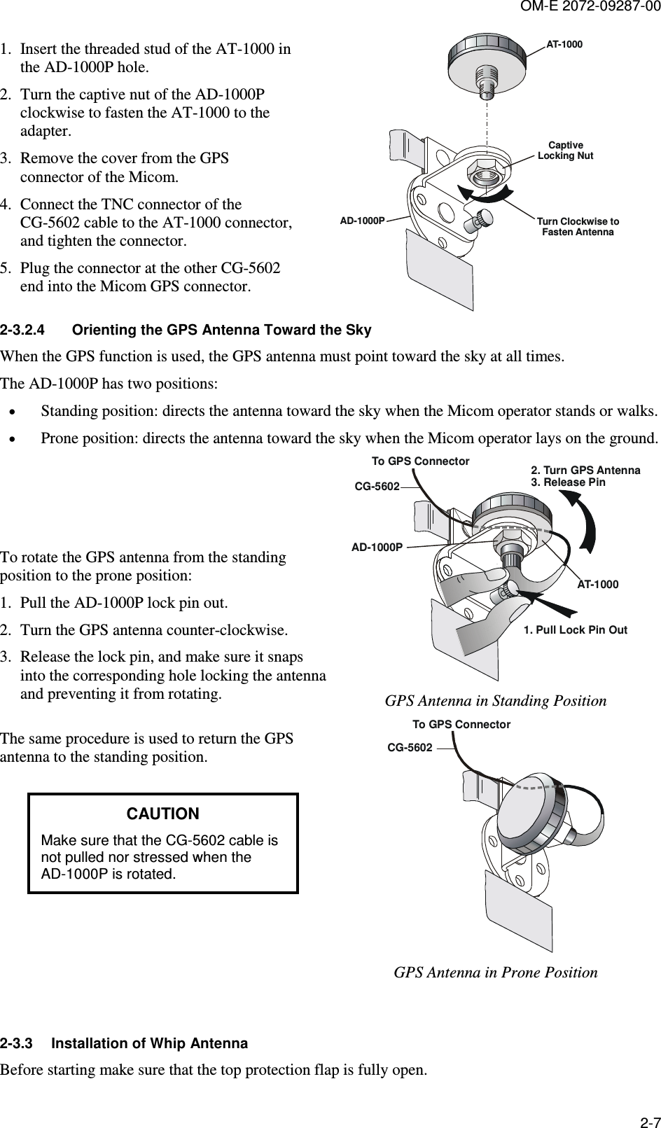
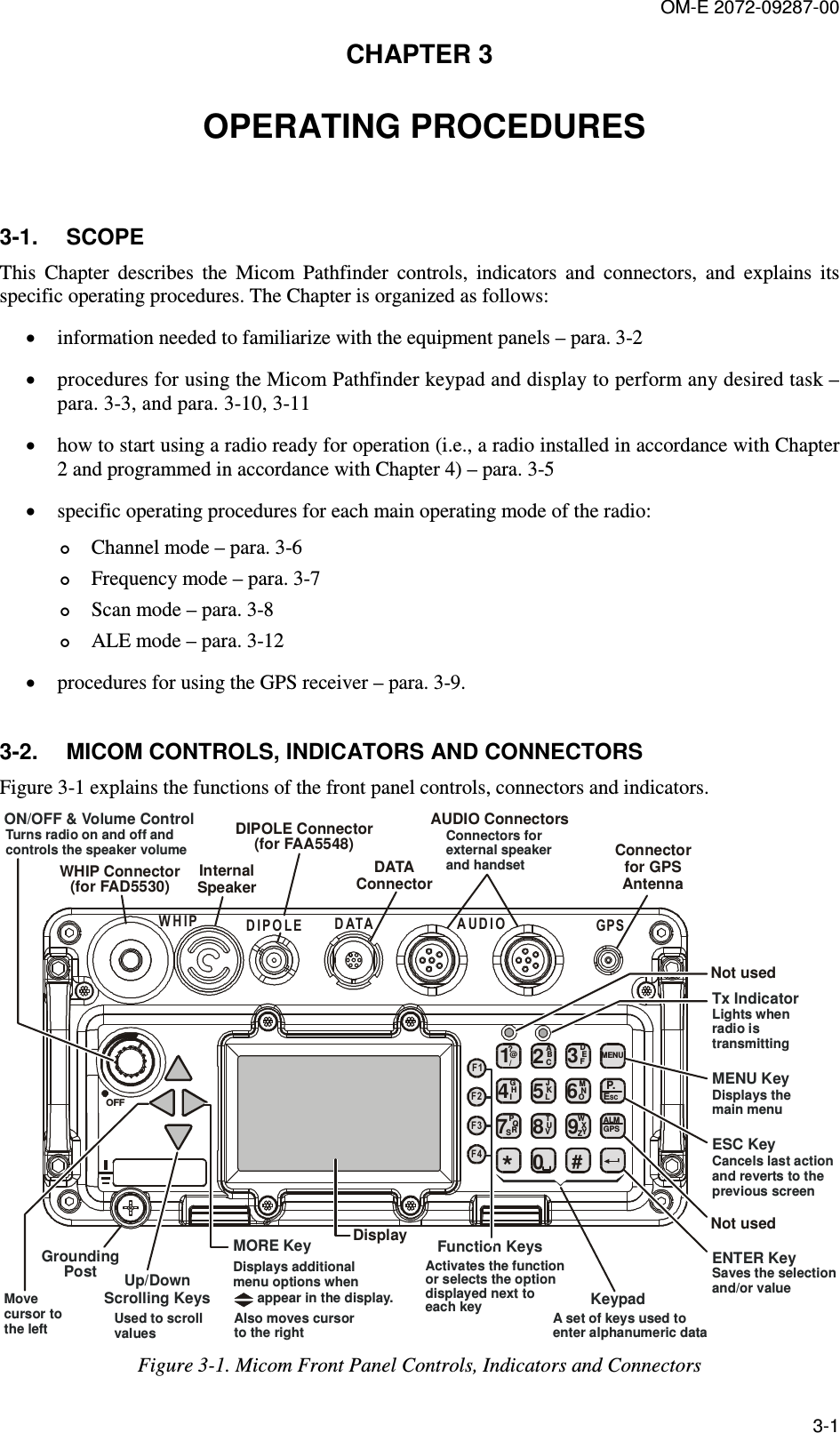
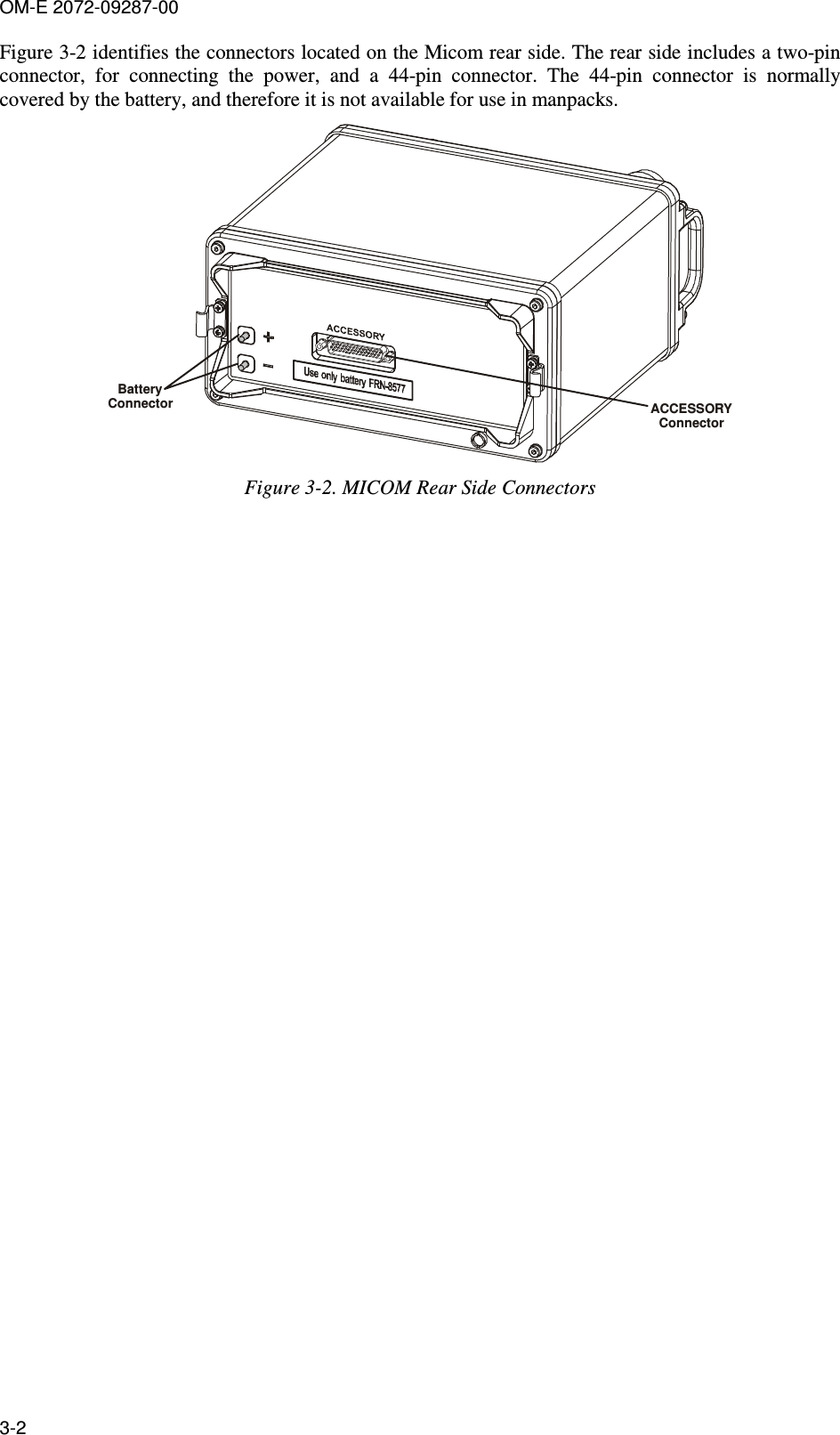
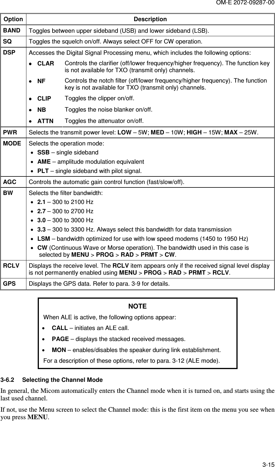
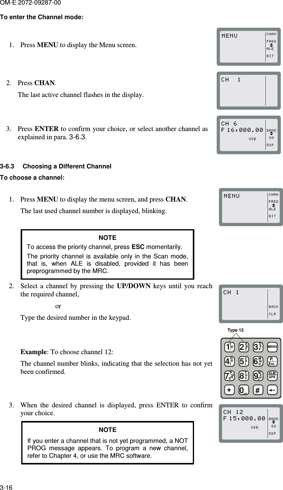
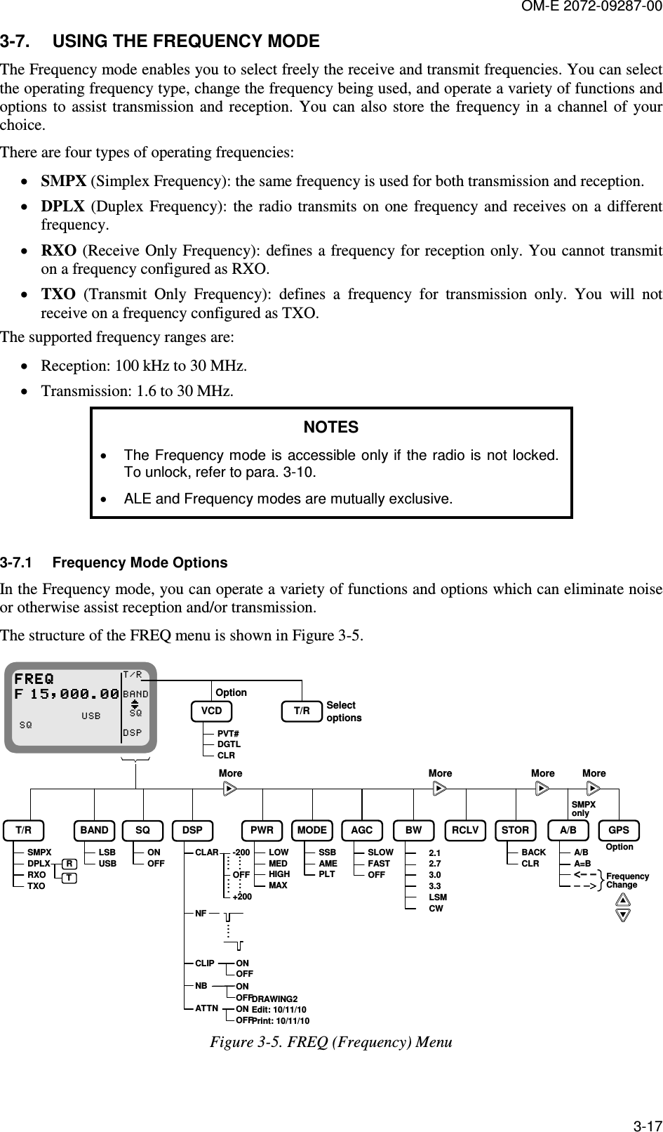
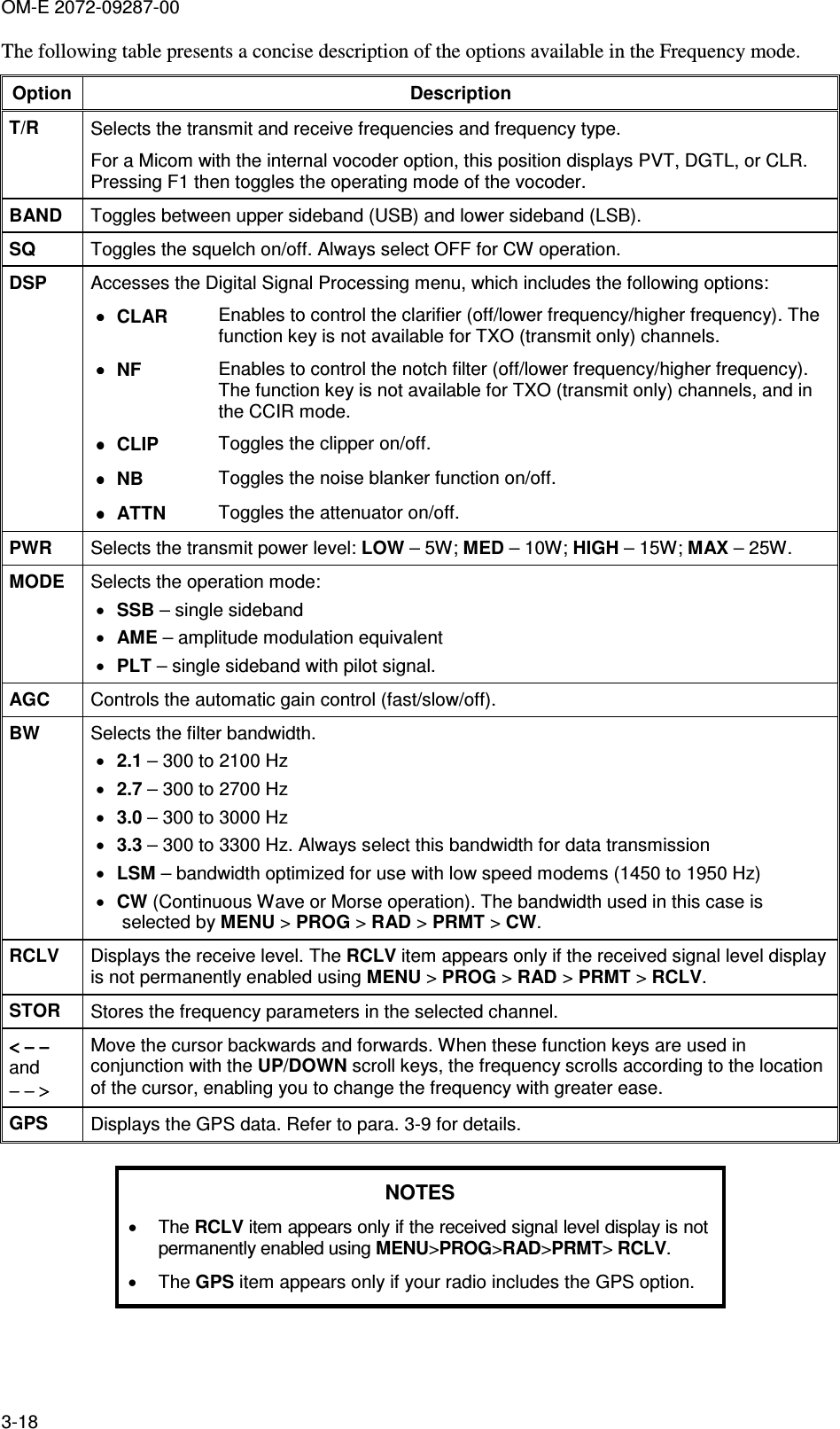
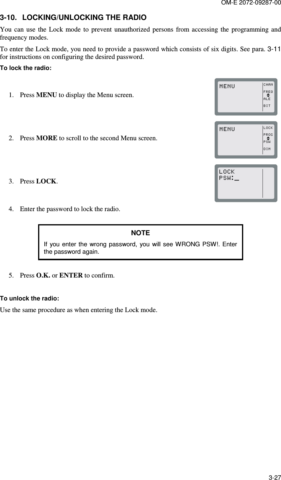
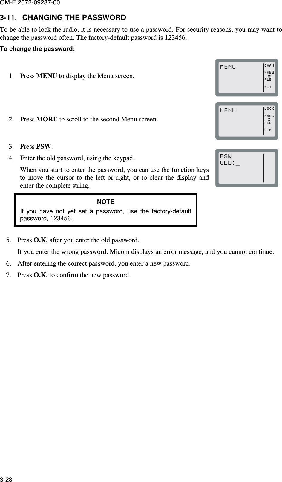
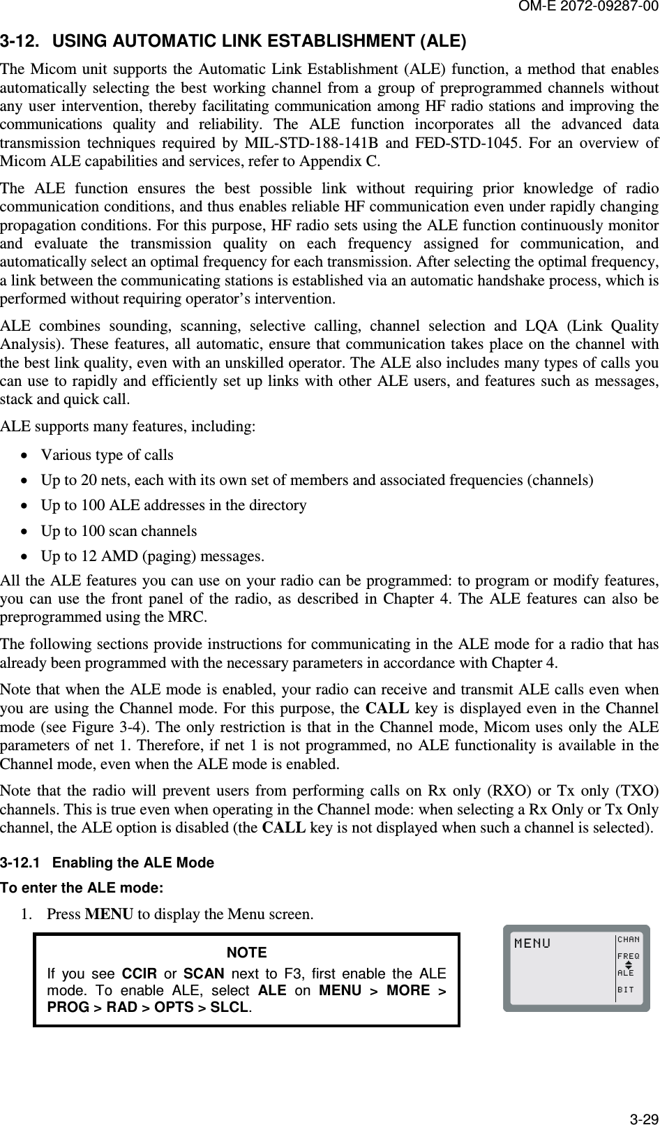
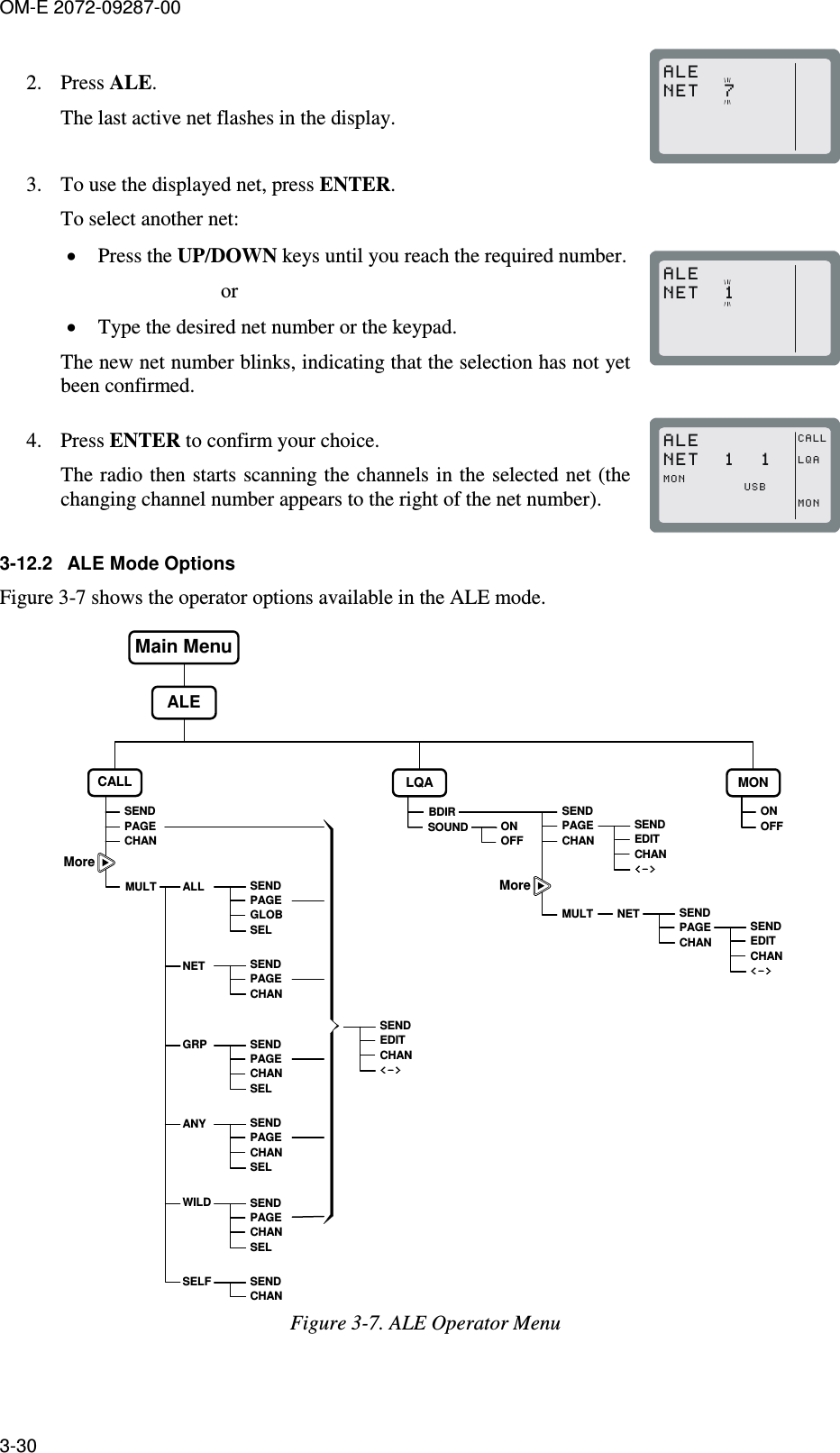
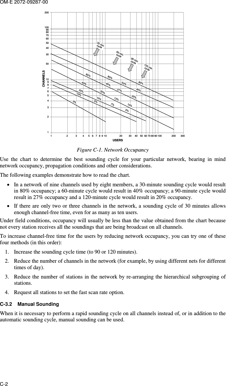
UN MicomPathFinder_Installation and Operation_Manual_OM-E-2072-09287-00-RevC_FCC

OM-E 2072-09287-00    INSTALLATION AND OPERATOR MAINTENANCE MANUAL FOR   Micom Pathfinder 5 - 25 Watt HF-SSB Manpack Transceiver     Revision C      NOVEMBER 2010
OM-E 2072-09287-00 i WARNINGS, CAUTIONS AND NOTES The  following  notations  are  used  to  place  special  emphasis  on  procedures,  or  to  call  attention  to precautionary measures. WARNING An operating procedure, practice and so forth, which if not followed correctly, could result in personal injury, or loss of life.  CAUTION An operating procedure, practice and so forth, which if not followed correctly, could result in damage to, or destruction of equipment.  NOTE An  operating  procedure,  condition  and  so  forth,  to  which  special  attention should be paid.  GENERAL SAFETY PRECAUTIONS  During transmission, high RF voltages may appear at the RF connectors, the antenna cable, and on the antenna itself.  Avoid  touching  the  antenna  and  the  RF  connectors  of  a  radio  set  while  it operates. Make sure the antenna is not located near high-voltage lines. Operating  and  maintenance  personnel  must  be  familiar  with  the  applicable safety requirements before attempting to install or operate the radio set.    WARNING Lithium-Ion  batteries  contain  dangerous  chemicals.  Handle  and  dispose  of Lithium-Ion  batteries  according  to  the  prescribed  safety  regulations.  In particular, observe the following precautions: 1.  Do not short-circuit Lithium-Ion batteries. 2.  Do not damage battery case and do not tamper with battery in any way. 3.  Do  not  try  to  recharge  the  battery,  except  by  means  of  the  supplied battery charger. 4.  Do not expose to heat or flame. 5.  Do not dispose of used Lithium-Ion batteries by burning.  CAUTION Do  not  transmit  with  radio  on  your  back.  Place  radio  on  ground  before starting  transmit/receive  communication,  and  connect  it  to  the  grounding spike in accordance with Chapter 2.
OM-E 2072-09287-00 ii FEDERAL COMMUNICATION COMMISSION REGULATIONS The  FCC  has  established  limits  for  safe  exposure  to  radio  frequency  (RF)  emissions  from  mobile two-way radios. The FCC requires manufacturers to demonstrate compliance with RF exposure limits before  mobile  two-way  radios  can  be  marketed  in  the  U.S.  When  two-way  radios  are  approved  for occupational/controlled environment exposure limits, the FCC requires users to be fully aware of, and exercise control over, their exposure. Awareness and control of RF exposure can be accomplished by education or training through appropriate means such as information and instructions in user manuals or  safety  booklets,  or  other  appropriate  means.  This  user  safety booklet includes useful information about RF exposure and helpful instructions on how to control your RF exposure. Your  two-way  radio  is  designed  and  tested  to  comply  with  a  number  of  national  and  international standards and guidelines (listed below) regarding human exposure to radio frequency electromagnetic energy.  This  radio  complies  with  the  IEEE  (FCC)  and  ICNIRP  exposure  limits  for occupational/controlled RF exposure environments  at  usage  factors  of up  to  10%  talk-90% listen. In terms  of  measuring  RF  energy  for  compliance  with  FCC  exposure  guidelines,  your  radio  radiates measurable RF energy only while it is transmitting (during talking), not when it is receiving (listening) or in standby mode. Your two-way radio complies with the following RF energy exposure standards and guidelines: •  United States Federal Communications Commission, Code of Federal Regulations; 47CFR part 2 sub-part J •  American  National  Standards  Institute  (ANSI)/Institute  of  Electrical  and  Electronic  Engineers (IEEE) C95.1-1992 •  Institute of Electrical and Electronic Engineers (IEEE) C95.1-1999 Edition •  International Commission on Non-Ionizing Radiation Protection (ICNIRP) 1998 •  Ministry  of  Health  (Canada)  Safety  Code  6:  Limits  of  Human  Exposure  to  Radiofrequency Electromagnetic Fields in the Frequency Range from 3 kHz to 300 GHz, 1999 •  Australian  Communications  Authority  Radiocommunications  (Electromagnetic  Radiation  – Human Exposure) Standard, 2001 •  ANATEL, Brasil Regulatory Authority, Resolution 256 (April 11, 2001). Additional Requirements for SMR, Cellular and PCS Product Certification.  SAFETY SUMMARY The  following  are  general  safety  precautions  that  are  not  related  to  any  specific  procedures  and therefore  do  not  appear  elsewhere  in  this  publication.  These  are  recommended  precautions  that personnel must understand and apply during various phases of operation and maintenance. KEEP  AWAY  FROM  LIVE  CIRCUITS.  Operating  personnel  must  at  all  times  observe  all  safety regulations.  Do  not  replace  components  or  make  adjustments  inside  the  equipment  with  the  high voltage  supply  turned  on.  Under  certain  conditions,  dangerous  potentials  may  exist  even  when  the power  control  is  in  the  OFF  position,  due  to  charges  retained  by  capacitors.  To  avoid  casualties, always remove power and discharge and ground a circuit before touching it. DO NOT SERVICE OR ADJUST ALONE. Under no circumstances should any person reach into the equipment enclosure for the purpose of servicing or adjusting the equipment except in the presence of someone who is capable of rendering aid. RESUSCITATION.  Personnel  working  with  or  near  high  voltages  should  be  familiar  with  modern methods of resuscitation. USE  SAFETY  APPROVED  EQUIPMENT.  When  cleaners  and  primers  are  being  applied,  approved explosion-proof lights, blowers, and other equipment shall be used. Insure that firefighting equipment is readily available and in working order. GIVE  CLEANERS  SPECIAL  CARE.  Keep  cleaners  in  special  polyethylene  bottles  or  in  safety  cans and in minimum quantities. Discard soiled cleaning cloths into safety cans.
OM-E 2072-09287-00 iii TABLE OF CONTENTS Page CHAPTER 1  GENERAL DESCRIPTION 1-1. SCOPE .......................................................................................................................... 1-1 1-2. PURPOSE AND USE .................................................................................................... 1-1 1-3. EQUIPMENT DESCRIPTION........................................................................................ 1-2 1-3.1 Micom Receiver/Transmitter.................................................................................... 1-2 1-3.2 Carrying Harness .................................................................................................... 1-3 1-3.3 FAD5530 Collapsible 9-Foot Whip Antenna ........................................................... 1-3 1-3.4 FAA5548 Portable Dipole Antenna ......................................................................... 1-4 1-3.5 GPS Antenna, AT-1000 (for Use with Option G421) ............................................... 1-4 1-3.6 Handset, FMN5501 ................................................................................................. 1-4 1-3.7 Loudspeaker, LS-108M (Optional) .......................................................................... 1-4 1-3.8 16 Ah Lithium-Ion Battery, FRN8577....................................................................... 1-5 1-3.9 Utilities..................................................................................................................... 1-5 1-4. TECHNICAL CHARACTERISTICS ............................................................................... 1-6 CHAPTER 2   INSTALLATION 2-1. SCOPE .......................................................................................................................... 2-1 2-2. UNPACKING ................................................................................................................. 2-1 2-3. MICOM PATHFINDER ASSEMBLY PROCEDURE...................................................... 2-2 2-3.1 Installation of Battery............................................................................................... 2-2 2-3.2 Installation in Carrying Harness .............................................................................. 2-3 2-3.3 Installation of Whip Antenna ................................................................................... 2-7 2-3.4 Connection of Audio Accessories............................................................................ 2-8 2-3.5 Wearing Backpack Carrying Harness ..................................................................... 2-8 2-3.6 Operating Micom Pathfinder on Ground.................................................................. 2-8 2-4. USING THE FAA5548 TACTICAL DIPOLE ANTENNA................................................ 2-8 CHAPTER 3   OPERATING PROCEDURES 3-1. SCOPE .......................................................................................................................... 3-1 3-2. MICOM CONTROLS, INDICATORS AND CONNECTORS ......................................... 3-1 3-3. FAMILIARIZATION WITH MICOM OPERATING PROCEDURES ............................... 3-3 3-3.1 Display Functions .................................................................................................... 3-3 3-3.2 Audible Indications .................................................................................................. 3-7 3-4. MENU STRUCTURE..................................................................................................... 3-8 3-4.1 Displaying the Main Menu ....................................................................................... 3-8 3-4.2 What you can Select on the Main Menu.................................................................. 3-9 3-4.3 Notational Conventions ........................................................................................... 3-9 3-5. GETTING STARTED................................................................................................... 3-10 3-5.1 Turning the Radio On and Off ............................................................................... 3-10 3-5.2 Preparation for Operation ...................................................................................... 3-11 3-5.3 Transmitting and Receiving................................................................................... 3-13 3-6. USING THE CHANNEL MODE ................................................................................... 3-14 3-6.1 Channel Mode Options.......................................................................................... 3-14 3-6.2 Selecting the Channel Mode ................................................................................. 3-15 3-6.3 Choosing a Different Channel ............................................................................... 3-16 3-7. USING THE FREQUENCY MODE.............................................................................. 3-17 3-7.1 Frequency Mode Options ...................................................................................... 3-17 3-7.2 Selecting the Operating Frequency in the FREQ Mode ........................................ 3-19 3-7.3 Storing Frequencies .............................................................................................. 3-22 3-8. USING THE SCAN MODE .......................................................................................... 3-23 3-8.1 Selecting the Scan Mode ...................................................................................... 3-23 3-8.2 Scan Mode Options............................................................................................... 3-23 3-9. USING THE GPS RECEIVER (OPTIONAL) ............................................................... 3-24 3-9.1 Overview of GPS Receiver Functions ................................................................... 3-24 3-9.2 How to Get the Best Results from your Micom GPS Receiver .............................. 3-24 3-9.3 Operating the GPS Receiver ................................................................................. 3-24 3-10. LOCKING/UNLOCKING THE RADIO ......................................................................... 3-27 3-11. CHANGING THE PASSWORD................................................................................... 3-28
OM-E 2072-09287-00 iv TABLE OF CONTENTS (Cont'd) Page 3-12. USING AUTOMATIC LINK ESTABLISHMENT (ALE)................................................. 3-29 3-12.1 Enabling the ALE Mode......................................................................................... 3-29 3-12.2 ALE Mode Options ................................................................................................ 3-30 3-12.3 Receiving and Transmitting Calls in ALE Mode .................................................... 3-31 3-12.4 Using ALE Mode to Send and Request GPS Position Data.................................. 3-57 3-13. USING THE VOCODER.............................................................................................. 3-58 3-13.1 Introduction............................................................................................................ 3-58 3-13.2 Using the Vocoder................................................................................................. 3-58 3-13.3 Programming the Vocoder .................................................................................... 3-59 3-14. OPERATION UNDER UNUSUAL CONDITIONS........................................................ 3-62 3-14.1 Operation in Desert Areas..................................................................................... 3-62 3-14.2 Operation at Low Temperatures............................................................................ 3-62 3-14.3 Operation During Storms....................................................................................... 3-62 CHAPTER 4   USING THE PROGRAMMING MODE 4-1. SCOPE .......................................................................................................................... 4-1 4-2. THE PROG MENU ........................................................................................................ 4-1 4-3. PROGRAMMING THE RADIO PARAMETERS ............................................................ 4-2 4-3.1 Programming Channels........................................................................................... 4-3 4-3.2 Configuring Radio Parameters ................................................................................ 4-5 4-3.3 Setting Radio Options ............................................................................................. 4-6 4-4. ALE PROGRAMMING................................................................................................... 4-7 4-4.1 Programming Nets .................................................................................................. 4-9 4-4.2 Setting the Net Options ......................................................................................... 4-11 4-4.3 Directory Parameters ............................................................................................ 4-11 4-4.4 AMD Message Configuration................................................................................. 4-11 4-4.5 ALE Options Configuration.................................................................................... 4-12 4-4.6 Auto Dial Parameters ............................................................................................ 4-13 4-4.7 Storing ALE parameters ........................................................................................ 4-14 4-4.8 Using the New Station Address Filter.................................................................... 4-14 CHAPTER 5  OPERATOR MAINTENANCE 5-1. GENERAL ..................................................................................................................... 5-1 5-2. VISUAL INSPECTION AND MECHANICAL CHECKS.................................................. 5-1 5-2.1 Inspection ................................................................................................................ 5-1 5-2.2 Cleaning .................................................................................................................. 5-2 5-3. CORRECTIVE MAINTENANCE.................................................................................... 5-3 APPENDIX A  USING BATTERY CHARGER, FRN8570B A-1. PURPOSE AND USE ....................................................................................................A-1 A-2. FRN8570B DESCRIPTION ...........................................................................................A-1 A-3. FUNCTIONAL DESCRIPTION......................................................................................A-1 A-4. FRN8570B OPERATING INSTRUCTIONS ..................................................................A-2 A-4.1 Familiarization with Charger Unit............................................................................. A-2 A-4.2 Preparations for Charging ....................................................................................... A-3 A-4.3 Charging Process.................................................................................................... A-3 A-5. MAIN FRN8570B TECHNICAL SPECIFICATIONS ......................................................A-4 APPENDIX B  INSTALLATION OF FAA5548 TACTICAL DIPOLE ANTENNA B-1. SCOPE .......................................................................................................................... B-1 B-2. FAA5548 DESCRIPTION ..............................................................................................B-1 B-3. ANTENNA CONFIGURATIONS....................................................................................B-1 B-3.1 Horizontal Dipole ..................................................................................................... B-2 B-3.2 Inverted V Dipole..................................................................................................... B-2 B-3.3 Sloping Dipole ......................................................................................................... B-3 B-3.4 Wire Antenna Configuration .................................................................................... B-4 B-4. FAA5548 INSTALLATION PROCEDURE.....................................................................B-4 APPENDIX C  ALE CAPABILITIES AND FEATURES C-1. SCOPE ..........................................................................................................................C-1 C-2. SCANNING....................................................................................................................C-1
OM-E 2072-09287-00 v TABLE OF CONTENTS (Cont'd) Page C-3. SOUNDING ...................................................................................................................C-1 C-3.1 Sounding Cycle Time .............................................................................................. C-1 C-3.2 Manual Sounding ....................................................................................................C-2 C-4. LQA MEMORY ..............................................................................................................C-3 C-5. BIDIRECTIONAL HANDSHAKE....................................................................................C-3 C-6. SELECTIVE CALLING ..................................................................................................C-4 C-6.1 ALE Addressing Method.......................................................................................... C-4 C-6.2 Address and Call Types ..........................................................................................C-4 C-7. USING THE MULTINET FEATURE ..............................................................................C-8 C-8. MESSAGES...................................................................................................................C-8 C-9. USING THE CALLER STACK .......................................................................................C-8 C-10. QUICK CALL .................................................................................................................C-9
OM-E 2072-09287-00 vi LIST OF ILLUSTRATIONS Page Figure  1-1.  Micom Pathfinder, General View................................................................................................. 1-1 Figure  1-2.  Micom Receiver/Transmitter........................................................................................................ 1-2 Figure  1-3.  Micom Pathfinder Carrying Harness,  General View (Closed for Transport) ............................ 1-3 Figure  1-4.  GPS Antenna, AT-1000 ............................................................................................................... 1-4 Figure  1-5.  GPS Antenna Adapter, AD-1000P .............................................................................................. 1-4 Figure  1-6.  Rechargeable Lithium-Ion Battery, FRN8577............................................................................. 1-5 Figure  1-7.  PC-Micom Data Cable ................................................................................................................. 1-5  Figure  2-1.  Installing the Battery ..................................................................................................................... 2-2 Figure  2-2.  Carrying Harness, Front View (Closed)....................................................................................... 2-3 Figure  2-3.  Carrying Harness with Front Flaps Raised ................................................................................. 2-4 Figure  2-4.  Installing Transceiver in Carrying Harness.................................................................................. 2-5 Figure  2-5.  Detail of  Transceiver in its Carrying Harness............................................................................. 2-6 Figure  2-6.  GPS Antenna Installed on Harness............................................................................................. 2-6  Figure  3-1.  Micom Front Panel Controls, Indicators and Connectors........................................................... 3-1 Figure  3-2.  MICOM Rear Side Connectors.................................................................................................... 3-2 Figure  3-3.  Main Menu .................................................................................................................................... 3-9 Figure  3-4.  Channel (CHAN) Menu .............................................................................................................. 3-14 Figure  3-5.  FREQ (Frequency) Menu...........................................................................................................3-17 Figure  3-6.  GPS Menu .................................................................................................................................. 3-25 Figure  3-7.  ALE Operator Menu ................................................................................................................... 3-30 Figure  3-8.  VCD Programming Menu...........................................................................................................3-60  Figure  4-1.  PROG Menu – Radio Parameters Programming....................................................................... 4-2 Figure  4-2.  PROG Menu – ALE Parameters Programming ......................................................................... 4-7  Figure  A-1.  Charger Unit, General View .........................................................................................................A-2  Figure  B-1.  Horizontal Dipole Configuration ...................................................................................................B-2 Figure  B-2.  Inverted V Configuration...............................................................................................................B-3 Figure  B-3.  Sloping Dipole Configuration........................................................................................................B-3  Figure  C-1.  Network Occupancy.....................................................................................................................C-2
OM-E 2072-09287-00 vii LIST OF TABLES Page Table  1-1.  DATA Connector, Pin Functions.................................................................................................. 1-8 Table  1-2.  AUDIO Connectors, Pin Functions.............................................................................................. 1-8  Table  5-1.  Visual Inspection and Mechanical Checks.................................................................................. 5-1 Table  5-2.  Fault Messages ............................................................................................................................ 5-4  Table  A-1.  Status Indications .........................................................................................................................A-2  Table  C-1.  Use of “@” Stuffing Symbol..........................................................................................................C-5 Table  C-2.  Use of “?” Wildcard Symbol .........................................................................................................C-6
OM-E 2072-09287-00 viii  Intentionally Left Blank
OM-E 2072-09287-00 1-1 CHAPTER 1  GENERAL DESCRIPTION 1-1.  SCOPE This manual provides instructions regarding the installation and operator maintenance of the Micom Pathfinder, a portable high-frequency (HF) single sideband (SSB) manpack radio set. The manual is organized as follows: Chapter 1    General Description: provides a general description of the Micom Pathfinder and its main components, and presents the main technical characteristics. Chapter 2    Installation: provides installation instructions for Micom Pathfinder. Chapter 3 Operating  Instructions:  describes  the  equipment  and  the  functions  of  the  various controls and indicators, and presents operating instructions.  Chapter 4    Using  the  Programming  Mode:  provides  detailed  instructions  for  programming  the Micom Pathfinder parameters needed in the various operating modes. Chapter 5    Operator Maintenance: provides operator maintenance instructions. Appendix A  Using Battery Charger, FRN8570B: provides instructions for using the FRN8570B to charge Micom Pathfinder battery, FRN8577. Appendix B  Installation  of  FAA5548  Tactical  Dipole  Antenna:  provides  concise  installation instructions for the FAA5548 tactical dipole antenna. Appendix C  ALE  Capabilities  and  Features:  provides  a  concise  description  of  the  ALE capabilities and features supported by Micom Pathfinder. 1-2.  PURPOSE AND USE Micom  Pathfinder,  a  manpack  version  of  the  robust Micom-3  mobile  radio,  is  an  advanced  HF-SSB transceiver  that  provides  a  complete  solution  to  the communication requirements in the crowded HF band. It is part of the Micom-3 family of HF/SSB radio sets, has  compatible  characteristics,  and  uses  the  same operating procedures as other Micom-3 radio sets. Micom Pathfinder has selectable transmit RF power of 5,  10,  15  and  25 W,  and  high  sensitivity.  Its  built-in automatic  antenna  tuner  supports  a  wide  range  of antennas, including a 2.7 meter (9 ft) whip which can be  easily  folded  for  storage.  For  static  operation, Micom Pathfinder can also be used with dipole, long wire and other types of broadband antennas. Micom  Pathfinder  can  be  ordered  with  an  optional internal GPS receiver that provides accurate time and navigation data.  Micom  Pathfinder  is  powered  by  a  rechargeable Lithium-Ion  battery,  and  is  carried  in  a  convenient, lightweight  harness  that  completely  envelops  the transceiver,  and  enables  carrying  all  the  necessary accessories.  Figure  1-1. Micom Pathfinder, General View
OM-E 2072-09287-00 1-2 The  Micom  Pathfinder  capabilities  provide  reliable  long-range  HF-SSB  radio  communications  in  a rugged  yet  lightweight  manpack  configuration.  Designed  to  meet  the  needs  of  users  who  carry  out on-foot  operations  in  remote  areas,  it  is  built  to  withstand  years  of  shock  and  vibration  as  well  as severe  weather  conditions.  Micom  Pathfinder  is  certified  for  dependability  and  durability,  and complies with the applicable sections of MIL-STD-810F and MIL-STD-810E. Micom Pathfinder supports voice and data communications. Micom Pathfinder supports data rates up to 4800 bps by means of an optional internal (embedded) modem. Extensive  use  of  digital  signal  processing  (DSP)  ensures  high  performance;  a  built-in  voice  quality system  with  proprietary  DSP  algorithms  filter  out  background  noise  and  elevates  sound  bytes providing exceptional communication clarity and voice quality. Many advanced features are standard, such as digital noise blanking and voice-activated digital squelch.  Optional features such as embedded data  modem,  embedded vocoder,  embedded  AES  encryption, etc.,  are  also available.  Moreover, the addition of new features and upgrading to future technologies are easily made by software updating. To  ensure  the  best  possible  communication  reliability,  Micom  Pathfinder  Automatic  Link Establishment (ALE) has been certified by the Joint Interoperability Test Center (JITC) to MIL-STD-188-141B.    In  addition,  the  ALE  function  also  provides  Automatic  Message  Display  (AMD),  that enables operators to exchange preprogrammed messages while establishing a link. The AMD function is  also  used  in  several  advanced  optional  features,  such  as  automatic  position  reporting  (either operator-initiated or in response to queries) when a GPS receiver is installed, and automatic adoption of the encryption key used by the transmitting station (provided the necessary key is available at the receiving station).  1-3.  EQUIPMENT DESCRIPTION This section describes the main equipment units of the Micom Pathfinder radio set.  1-3.1  Micom Receiver/Transmitter  The Micom receiver/transmitter unit performs the following main functions: • Generates the transmit signals. • Demodulates the received signals.  • Processes the GPS signals (optional). • Provides the interfaces to the operator, and to data equipment using Micom Pathfinder for radio communications. Figure  1-2 shows a general view of Micom, including its battery box.  Figure  1-2. Micom Receiver/Transmitter     The  Micom  is  a  complete  HF/SSB  receiver-transmitter,  powered  by  a  14.4  V  Lithium-Ion  battery installed in a battery box attached to the rear side of the Micom by two clamps. The box houses the battery and protects the battery against environmental elements.
OM-E 2072-09287-00 1-3 The nominal output impedance of the Micom is 50 Ω, and therefore it can  be directly connected to broadband  antennas  (dipoles,  traveling  wave  antennas,  delta  and  semi-delta  antennas).  An  internal antenna tuner enables using various whip antennas (in addition to the 2.7 meter (9 ft) antenna offered as a standard for the Micom Pathfinder). The transmitter includes antenna mismatch protection: if the VSWR (Voltage Standing Wave Ratio) is too high, for example, because the antenna is disconnected or damaged, the transmission will be inhibited to avoid damage, and a message will be displayed. In addition,  if  for  any  reason,  the  transmitter  internal  temperature  exceeds  the  maximum  permitted temperature, the transmitter output power is automatically reduced to avoid fault due to excessive heat.  The Micom has an  intelligent, user-friendly man-machine interface that  enables easy operation. The display provides feedback to the operator and shows extensive information concerning system status (e.g., mode of operation, link status, call progress indications, low battery condition, etc.), as well as the GPS data (when this option is used). Support for multiple languages is also available. 1-3.2  Carrying Harness Micom Pathfinder carrying harness consists of a  lightweight  nylon  harness  with  adjustable shoulder  straps  that  enable  carrying  all  the necessary  accessories.  Additional  waist  and breast straps, also easily adjustable for best fit and user’s comfort, stabilize the harness while walking and running. A  foldable  rear  support  enables  placing  the harness  on  ground,  vertically,  for  dismounted operation. CAUTION During dismounted operation, use the supplied grounding spike and strap  to  ground  the  Micom Pathfinder unit.   Figure  1-3. Micom Pathfinder Carrying Harness,  General View (Closed for Transport) For best equipment protection, the carrying harness completely envelops the transceiver. A front flap with zippers provides easy access to the internal storage compartments for cables and spare battery, and also  permits the installation  of the Micom transceiver.  After installing the transceiver, the  front flap  remains  closed:  a  separate  top  flap  can  be  opened  to  access  the  Micom  front  panel,  install  the antenna and the handset, and operate the radio set. Side  pouches can be used to carry the folded whip antenna, and other accessories. The optional GPS antenna is attached to the side of the harness. 1-3.3  FAD5530 Collapsible 9-Foot Whip Antenna The  FAD5530  whip  antenna  is  the  standard  Micom  Pathfinder  antenna  used  for  short-range ground-wave communication, and  is suitable for portable operation. Antenna matching is performed by the Micom internal automatic antenna tuner, and thus FAD5530 is directly connected to the WHIP connector of the Micom. The FAD5530 whip antenna consists of two components: • AT-271A Collapsible Antenna. The antenna is composed of six sections. Each section fits into the  end  of  a  wider  section.  A  stainless-steel  plastic-covered  cable  (or  braided  plastic  cord), under  spring  tension,  is  threaded  through  the  sections  to  keep them  together  when  operating. When the sections are folded, the cable keeps them together as a group, to prevent the loss of individual sections. Spring tension is provided by a spiral spring in the base section.
OM-E 2072-09287-00 1-4 • AB-591 Antenna  Base  Adapter.  The  antenna  base  adapter  serves  as  the  main support  for  the AT-271A. A safety strap is supplied to fasten the antenna sections together, when the radio set is transported with the antenna folded. 1-3.4  FAA5548 Portable Dipole Antenna The optional FAA5548 dipole antenna is a lightweight portable antenna for the frequency range of 2 to 30 MHz.  This  antenna  is  recommended  for  use  during  static  operation,  when  long  communication ranges  are  required:  when  using  a  properly  selected  operating  frequency,  FAA5548  provides continuous coverage for communication ranges of up to 1,000 kilometers. The FAA5548 antenna consists of two antenna wires, which are attached to an insulator (center unit). The insulator is connected by means of the coaxial feed cable to the front-panel DIPOLE connector. The length of the antenna wires is coarsely adjusted in accordance with the operating frequency. Two cords are used to stretch the wires. The cords are fastened to nearby supports, e.g. trees, poles, etc. When properly adjusted to the operating frequency range, the FAA5548 input impedance is close to 50 Ω,  and  therefore  it  is  possible  to  connect  FAA5548  directly  to  the  DIPOLE  connector  of  the Micom. When the selected operation mode involves automatic changing of the operating frequency, e.g., for ALE operation, the antenna should be adjusted to the average operation frequency.  1-3.5  GPS Antenna, AT-1000 (for Use with Option G421) The GPS antenna, AT-1000, is a compact active omnidirectional antenna which connects to the GPS connector  of  the  Micom  through  a  coaxial  cable  that  carries  both  DC  power  and  the  received  GPS signals. The AT-1000 has a threaded stud on its base, which can be used to fasten the antenna to an appropriate adapter. Figure  1-4 shows a general view of the antenna.  Figure  1-4. GPS Antenna, AT-1000   For use  in Micom Pathfinder, the  required adapter is AD-1000P, and  the  coaxial  cable  is CG-5602. AD-1000P is used to attach the AT-1000 to the Micom Pathfinder carrying harness. Figure  1-5 shows a general view of the antenna adapter. Figure  1-5. GPS Antenna Adapter, AD-1000P  1-3.6  Handset, FMN5501 FMN5501 is a dynamic handset with a noise-suppression microphone complying with MIL-H-49078 (EL). It has a five-pin audio connector for connection to one of the Micom AUDIO connectors. 1-3.7  Loudspeaker, LS-108M (Optional) The LS-108M is a portable 0.3 W loudspeaker that connects to one of the AUDIO connectors on the front panel of the Micom. The LS-108M is designed for field combat use, and may be attached to a belt  or  harness.  It  allows  a  commander  to  monitor  radio  communications  while  the  radio  operator remains in full control of the radio set.
OM-E 2072-09287-00 1-5 A volume control on the housing provides adjustable sound level. The loudspeaker has an additional AUDIO connector, which permits the connection of an additional handset. 1-3.8  16 Ah Lithium-Ion Battery, FRN8577 FRN8577 is a rechargeable Lithium-Ion battery that provides a  14.4  V nominal voltage, and  a  nominal capacity  of  16  ampere-hours.  The  battery  has  a plastic outer case with safety vent. The battery has two  connectors,  one  for  powering  the  transceiver, and  the  other  for  charging.  Internal  electronic circuits protect against short-circuits, undervoltage, excessive temperature, and overcharging. ChargeConnectorRadioConnector Figure  1-6. Rechargeable Lithium-Ion Battery, FRN8577 1-3.8.1  Battery Charger, FRN8570B FRN8570B is a portable automatic battery charger for FRN8577 rechargeable Lithium-Ion batteries. FRN8570B can be powered from 100 to 240 VAC, 50/60 Hz. Its operation is fully automatic, and thus ensures  full  charging  of  batteries  to  their  rated  capacity,  while  prolonging  the  operational  life  of batteries by providing optimum charging conditions. Refer to Appendix A for additional information. 1-3.9  Utilities To  fully  and  efficiently  utilize  the  Micom  Pathfinder’s  advanced  capabilities,  the  following  utility packages are offered as options: • The  radio  operational  parameters  can  be  programmed  using  the  Micom  Radio  Control Application  (MRC),  option  FVN4841  (G424).  For  further  details,  refer  to  “Micom  Radio Control Application Owner’s Guide”, Publication OM-E 2072-09602-10.  • Data  communications  are  supported  by  the  MicomNET  e-Mail/Gateway  over  HF  Software Package,  covered  by  the  “MicomNET  e-Mail/Gateway  over  HF  Software  Package  User’s Guide”, Publication 6886864J01. All the utilities listed above run on PCs using the Windows(™) operating system, and require two of the  serial  RS-232  asynchronous  (COM)  ports  of  the  PC  for  communication  with  the  Micom receiver/transmitter: COM2 is used as the radio control port, and  COM1 is  used as the modem data port.  A  special  data  cable is  available  for  connecting  the  two  PC  serial  ports  to  the  Micom  DATA connector. OrientationDotPC-COM1PC-COM2 Figure  1-7. PC-Micom Data Cable
OM-E 2072-09287-00 1-6 1-4.  TECHNICAL CHARACTERISTICS  General Model   M95AMN0KV5-K+G873 Transmit Frequency Range   1.6 to 30 MHz Receive Frequency Range   0.1 to 30 MHz (0.1 to 1.6 MHz reduced performance) RF Impedance  • DIPOLE connector: 50 Ω  • WHIP connector: internal automatic tuner for whip antenna  Number of Channels  200 simplex or half duplex, user programmable Scanning  • 5 groups with up to 100 channels per group, including 1 guard channel. • Programmable scan rate: 1 to 5 sec. per channel, in 1 sec. steps ALE  MIL-STD-188-141B, JITC certified, MultiNet support Frequency Stability   0.6 ppm (0.1 ppm optional)  Frequency Resolution  10 Hz Data and Remote Control Interfaces RS-232C  Modes of Operation  • SSB (USB or LSB, user-selectable)  • PILOT • AME Services  • Analog voice • Digital voice (internal low-rate vocoder) • Data using internal modem (50 to 4800 bps) • COMSEC (digital NIST-certified advanced encryption system (AES), available as option for the vocoder and/or internal modem, internal storage of up to 7 keys) Audio Bandwidth  Automatic switching between voice and data   Voice Bandwidth   350 to 2700 Hz    Data Bandwidth  Operator-selectable: 2.1 kHz:   350 to 2100 Hz 3.0 kHz:  350 to 3000 Hz 3.3 kHz:  350 to 3300 Hz (also used by internal modem) Operating Voltage  13. 8 VDC ±20%, negative ground Dimensions  110 H × 222 W × 220 D mm (4.33 H × 8.74 W × 8.66 D inch) Weight (without battery)  3.6 kg (7.93 lb)
OM-E 2072-09287-00 1-7 Battery     Type   Lithium-Ion, rechargeable   Capacity  16 Ah   Nominal Voltage   14.4 V   Minimum Voltage   10.0 V   Maximum Continuous    Current  13 A   Operating Temperature   Range -30 to +50°C/-22 to +122ºF   Charging Temperature    Range 0 to +50°C/32 to +122ºF   Dimensions (H × W × L)  78.5 × 72.6 × 187.5 mm (3.09 × 2.86 × 7.38 inch)   Weight  1.8 kg Temperature Range     Operating  -30 to +60°C/-22 to +140ºF   Storage   -40 to +85°C/-40 to +185ºF Humidity  Max. 95% at 50°C Shock and Vibration  MIL-STD-810E and MIL-STD-810F Transmitter Output Power  5, 10, 15, 25 W P.E.P and average, user-selectable TX/RX Switching Time  10 msec Tx Tuning Adjustments  None Current Consumption  (single tone) Max 11A Receiver Sensitivity (SINAD) SSB  • 0.5 µV for 10 dB SINAD (0.35 µV typical) • 0.1 to 1.6 MHz with reduced performance Audio Power at Speaker  External 5W @ 2.5% distortion Squelch  Constant SINAD (digital) Clarifier Range  ±200 Hz in 10 Hz steps  Current Consumption   • Max 0.9A without modem • Max 1.1A with modem option
OM-E 2072-09287-00 1-8 Connectors  Table  1-1. DATA Connector, Pin Functions Pin  Description 1  Not connected  2  Serial control communication transmit output (to RADIO connector) 3  Serial control communication receive input (to RADIO connector) 4  Not connected  5  Ground line 6  Serial data communication transmit output (to RADIO and MODEM connectors) 7  Serial data communication receive input (to RADIO and MODEM connectors) Table  1-2. AUDIO Connectors, Pin Functions Pin  Description A  Ground line B  Receive audio output to external speaker C  Activates transmission by short to ground D  Input audio signals generated by the microphone (600 Ω impedance; 6 mV tone is required for full output power) E  Receive audio output (600 Ω) to earphone F  Power output to microphone
OM-E 2072-09287-00 2-1 CHAPTER 2   INSTALLATION 2-1.  SCOPE This Chapter provides installation instructions for Micom Pathfinder.  WARNING Lithium-Ion batteries, FRN8577, contain dangerous chemicals. Handle and dispose of Lithium-Ion batteries according to the prescribed safety regulations. In particular, observe the following precautions: 1.  Do not short-circuit Lithium-Ion batteries, FRN8577. 2.  Do not damage battery case and do not tamper with battery in any way. 3.  Do not expose to heat or flame. 4.  Do not dispose of Lithium-Ion batteries by burning or incinerating. 5.  Always charge battery only with the FRN8570B charger. 2-2.  UNPACKING a. A  preliminary  inspection  of  the  equipment  containers  should  be  made  prior  to  unpacking.  Evidence of damage should be noted and reported immediately to the proper authorities. Unpack the equipment as follows:  (1) Place each container on a clean flat surface, cut all straps, and open or remove the top.  (2) Take out each item carefully and place it securely on a clean surface.  (3) Remove the packing material while looking for small items.  (4) Fold and store the containers and packing materials for future use. b. Checking Unpacked Equipment.  (1) Inspect all items for damage.  Immediately report any damage found.  (2) Check  all  items  against  the  items  listed  in  the  accompanying  packing  slip  and/or  the appropriate list of items given in the equipment manual.  (3) Report  any  missing  items  or  discrepancies.    Shortage  of  a  minor  part  which  does  not affect the proper functioning of the equipment should not prevent use of the equipment.
OM-E 2072-09287-00 2-2 2-3.  MICOM PATHFINDER ASSEMBLY PROCEDURE The assembly of a Micom Pathfinder radio set and its preparation for operation includes the following steps: • Installation of Micom battery • Installation in carrying harness • Installation of antenna and audio accessories • Wearing the carrying harness. 2-3.1  Installation of Battery 1. Check that the volume/power control of the Micom Pathfinder is set to the fully counter-clockwise detent position, OFF. 2. Place the unit face down on a clean, flat surface. 3. Release the two clamps holding the battery cover on the bottom of the unit and remove the cover. 4. Remove old battery, if any. 5. Align battery connector with the two power pins protruding from the bottom of the unit, and push the battery in place. 6. Visually check battery cover for dirt or damage. Clean if necessary. 7. Reinstall the battery cover and fasten with the two clamps.  BatteryConnectorBattery, FRN8577BatteryCover Figure  2-1. Installing the Battery
OM-E 2072-09287-00 2-3 2-3.2  Installation in Carrying Harness  2-3.2.1  Familiarization with Carrying Harness Figure  2-2 shows a general front view of the closed carrying harness. The harness can be weared on the operator’s back, or placed on the ground, using the rear support to hold it in a vertical position. Front FlapTop ProtectionFlapAttach GPS Antenna Adapter to one of these StrapssAdjustmentBucklesAdjustmentBucklesRear Support(Deployed Position)WaistStrapShoulder StrapBreast StrapSide AccessoriesPouchesLoudspeakerPocket Figure  2-2. Carrying Harness, Front View (Closed) The carrying harness transceiver compartment is closed by a  front flap,  which can  be unzipped and raised  as  shown  in  Figure   2-3.  This  provides  full  access  to  the  interior  of  the  carrying  harness  for installing  the  transceiver, or  retrieving stored  items  (spare  battery,  charger,  cables,  etc.).  Additional storage pouches for large accessories, e.g., folded whip antenna, handset, etc., are located on the sides of  the  carrying  harness.  The  optional  GPS  antenna  (mounted  on  the  adapter,  AD-1000P)  can  be attached to one of the top side straps (either on the left or right hand side of the harness). The optional portable loudspeaker, LS-108M, can be inserted in a special pocket at the right-hand side, or attached with  a  strap  to  the  harness.  During  operations,  the  audio  accessory  (handset  or  microphone)  can  be attached with a strap to the front side of the desired shoulder strap. In  addition  to  the  front  flap,  the  carrying  harness  has  a  top  protection  flap:  when  the  front  flap  is closed, it is possible to open the top flap to gain access to the Micom front panel and to most of the stored items.  Figure  2-3 shows the carrying harness with the front flap open. Note the internal storage pockets, and in  particular  the  spare  battery  compartment.  The  transceiver,  with  battery,  is  installed  in  the compartment located above the spare battery storage, behind a restrainer plate. After the transceiver is in place, the restrainer is pressed against the transceiver body by tightening the four side restraining straps. Two additional top restraining straps, passing along the sides of the transceiver, are attached to the  handles,  to  prevent  vertical  movement.  After  the  transceiver  is  secured,  the  front  flap  can  be closed.
OM-E 2072-09287-00 2-4 Spare BatteryCompartmentTransceiver RestrainingSide Straps(4 places)Top TransceiverRestraining StrapsPassthrough Slots for CablesFront Flapin Open PositionCable StoragePocketInternal StoragePockets Restrainer Figure  2-3. Carrying Harness with Front Flaps Raised 2-3.2.2  Installation Procedure  1. Place the carrying harness on a clean, level surface. 2. Release the four straps (two on each side). 3. Unzip the front flap, and then raise the flap as shown in Figure  2-4. 4. If necessary, store a spare battery in its storage compartment. 5. Release the two top transceiver restraining straps, and the four side restraining straps. 6. Orient the transceiver as shown in Figure  2-4, and then place it in position, behind the restrainer plate.
OM-E 2072-09287-00 2-5 Front Flap      in Open Position1. Open Top and          Side Transceiver             Restraining Straps  (6 places)2. Insert TransceiverInsert Spare Batteryin Storage Compartment Figure  2-4. Installing Transceiver in Carrying Harness  7. Fasten the four transceiver restraining straps to secure the transceiver behind the restrainer plate. 8. Pass each top transceiver restraining strap over the corresponding transceiver handle, and fasten the straps. See detail of transceiver installed in harness in Figure  2-5. 9. Ensure all transceiver restraining straps are tight. 10. Place all the items to be stored inside the carrying harness in the corresponding storage pockets. 11. Close the front flap and secure with its zipper. 12. Insert  all  the  items  to  be  stored  in  the  side  accessories  pouches,  close  the  pouches,  and  then secure the pouches with the corresponding straps.
OM-E 2072-09287-00 2-6 Top Restraining Straps(2 places) Figure  2-5. Detail of  Transceiver in its Carrying Harness  2-3.2.3  Installation of Optional AD-1000P and GPS Antenna AT-1000 1. If the optional GPS receiver will be in use, insert the GPS support strap in the top loop of the optional AD-1000P, and slide the AD-1000P in place. 2. Insert the other end of the AD-1000P in a suitable slot, as shown in Figure  2-6, and then secure the AD-1000P by fastening the strap. GPS AntennaSupport StrapAT-1000AD-1000PCG-5602 Figure  2-6. GPS Antenna Installed on Harness
OM-E 2072-09287-00 2-7 1. Insert the threaded stud of the AT-1000 in the AD-1000P hole.  2. Turn the captive nut of the AD-1000P clockwise to fasten the AT-1000 to the adapter. 3. Remove the cover from the GPS connector of the Micom. 4. Connect the TNC connector of the CG-5602 cable to the AT-1000 connector, and tighten the connector.  5. Plug the connector at the other CG-5602 end into the Micom GPS connector. Turn Clockwise to Fasten AntennaAD-1000PAT-1000CaptiveLocking Nut 2-3.2.4  Orienting the GPS Antenna Toward the Sky When the GPS function is used, the GPS antenna must point toward the sky at all times. The AD-1000P has two positions: • Standing position: directs the antenna toward the sky when the Micom operator stands or walks. • Prone position: directs the antenna toward the sky when the Micom operator lays on the ground. To rotate the GPS antenna from the standing position to the prone position: 1. Pull the AD-1000P lock pin out. 2. Turn the GPS antenna counter-clockwise. 3. Release the lock pin, and make sure it snaps into the corresponding hole locking the antenna and preventing it from rotating.  The same procedure is used to return the GPS antenna to the standing position.   CAUTION Make sure that the CG-5602 cable is not pulled nor stressed when the AD-1000P is rotated. 2. Turn GPS Antenna3. Release PinAT-1000To GPS ConnectorCG-56021. Pull Lock Pin OutAD-1000P GPS Antenna in Standing Position To GPS ConnectorCG-5602 GPS Antenna in Prone Position  2-3.3  Installation of Whip Antenna Before starting make sure that the top protection flap is fully open.
OM-E 2072-09287-00 2-8 To install the antenna: 1. Remove cover from the WHIP connector on the Micom front panel. 2. Visually check the connector for dirt or damage. Clean if necessary. 3. Screw antenna support AB-591 into the Micom WHIP connector. Tighten by hand only. 4. Extend the whip, and secure all sections by inserting them one into the other by hand. 5. Screw whip antenna sections into antenna support, AB-591. NOTE When the radio set is not in use, you may fold the antenna without disconnecting it from the WHIP connector. In this case, fasten the folded sections using the safety belt supplied with the antenna. Before starting transmission, make sure to release the safety belt and extend the antennas. To remove the whip antenna, perform the above tasks in the reverse order. CAUTION When folding the whip, always start with the upper section, otherwise it may be damaged. 2-3.4  Connection of Audio Accessories Connect the handset, FMN5501, to either of the AUDIO connectors on the front panel of the Micom. You may secure the handset to the front side of a supporting strap. If the  optional LS-108M loudspeaker is used, insert it in the pocket and secure it with the straps, or attach it with a strap passing through its top and bottom hooks. Connect the loudspeaker cable to one of  the  AUDIO  connectors  on  the  front  panel  of  the  Micom.  Route  the  audio  cables  through  the dedicated passthrough slots on the back of the harness. 2-3.5  Wearing Backpack Carrying Harness To wear backpack: • Put harness on your back by inserting arms through shoulder straps.  • Tighten shoulder straps if necessary by adjusting the strap buckles. • Buckle waist straps to belt and adjust to size.  • Adjust the breast strap length and then attach the strap. At this stage, the Micom Pathfinder is ready for use as a manpack radio set. 2-3.6  Operating Micom Pathfinder on Ground To operate the Micom Pathfinder on the ground, place the backpack on a flat, dry area, and deploy the rear support to stabilize the harness in a standing position. For safety, and to achieve best perform, ground the Micom Pathfinder: drive the grounding spike into the ground close to the radio, and then connect the grounding strap between the front panel grounding post and the grounding spike. 2-4.  USING THE FAA5548 TACTICAL DIPOLE ANTENNA In static operation, the Micom Pathfinder can be used with an FAA5548 tactical dipole antenna. Refer to Appendix B for FAA5548 installation and operation instructions.
OM-E 2072-09287-00 3-1 CHAPTER 3   OPERATING PROCEDURES 3-1.  SCOPE This  Chapter  describes  the  Micom  Pathfinder  controls,  indicators  and  connectors,  and  explains  its specific operating procedures. The Chapter is organized as follows: • information needed to familiarize with the equipment panels – para.  3-2 • procedures for using the Micom Pathfinder keypad and display to perform any desired task – para.  3-3, and para.  3-10,  3-11 • how to start using a radio ready for operation (i.e., a radio installed in accordance with Chapter 2 and programmed in accordance with Chapter 4) – para.  3-5 • specific operating procedures for each main operating mode of the radio:  Channel mode – para.  3-6  Frequency mode – para.  3-7  Scan mode – para.  3-8  ALE mode – para.  3-12 • procedures for using the GPS receiver – para.  3-9. 3-2.  MICOM CONTROLS, INDICATORS AND CONNECTORS Figure  3-1 explains the functions of the front panel controls, connectors and indicators.  GPSF1F2F3F4D ATAD I P O L EW H I P1?@AGJTDMWPBHKUENXQCILVFOYRZS/234567890#*ALMGPSP.ESCMENUA U D I OOFFInternal SpeakerDisplayDATAConnectorConnectorfor GPSAntennaNot usedNot usedUp/Down Scrolling KeysUsed to scrollvaluesMovecursor tothe leftON/OFF & Volume ControlTurns radio on and off and controls the speaker volumeAUDIO ConnectorsConnectors forexternal speakerand handsetTx IndicatorLights whenradio istransmittingKeypadA set of keys used to enter alphanumeric dataFunction KeysDisplays the main menuMENU KeyCancels last actionand reverts to the previous screen ESC KeySaves the selectionand/or valueENTER KeyMORE KeyDisplays additionalmenu options when appear in the display.Also moves cursor to the rightWHIP Connector(for FAD5530)DIPOLE Connector(for FAA5548)GroundingPostActivates the function or selects the option displayed next to each key Figure  3-1. Micom Front Panel Controls, Indicators and Connectors
OM-E 2072-09287-00 3-2 Figure  3-2 identifies the connectors located on the Micom rear side. The rear side includes a two-pin connector,  for  connecting  the  power,  and  a  44-pin  connector.  The  44-pin  connector  is  normally covered by the battery, and therefore it is not available for use in manpacks. BatteryConnectorACCESSORYConnector Figure  3-2. MICOM Rear Side Connectors
OM-E 2072-09287-00 3-3 3-3.  FAMILIARIZATION WITH MICOM OPERATING PROCEDURES  This section provides general procedures that will help you start using your radio and get the most of its advanced features. Most of the activities that can be performed by you (selection of operating mode, programming, testing, etc.)  are done using  the keypad together with the navigation and  function keys, and the front panel display. To simplify operation, Micom function keys operate as soft keys and therefore they permit you control the radio  simply and  efficiently, using a  menu-driven mode that  guides  you and helps you make the required  selections.  “Menu-driven”  simply  means  that  whenever  you  must  select  a  parameter,  an operating mode, etc., you select it from a list of allowed values displayed on the front panel display, thereby reducing the chance of error: • To make a selection, you use navigation keys to reach the desired parameter value or action, and then confirm the selection by pressing the ENTER   key. • To go back to previous options, or cancel the current selection or action, press the ESC P.ESC key. 3-3.1  Display Functions  3-3.1.1  Display Organization PWRMODEAGC BWCH  6F 16,000.00NFUSB NBCLARISQ  BW3.3AGC1267543 No.   Designation   Description 1  Mode indicator  Indicates the current working mode (e.g., channel, frequency, ALE, etc.) or the action being performed (e.g., programming, testing, etc.) 2  Work area  Displays information on the current working mode, the main operating parameters, the active options, status, etc. 3  Transmit level indicator  In the transmit mode, displays the relative transmit power 4  Receive level indicator  In the receive mode, displays the relative received signal strength 5  Tx bar  Appears when the radio is transmitting 6  More options Icon  The presence of this icon indicates that more options can be displayed in the options area. When this icon appears, press the MORE key to see menu options 7  Options display area  Displays a list of options you can select, by pressing the corresponding key, in the current working mode
OM-E 2072-09287-00 3-4 3-3.1.2  Mode and Function Indications  The following indications may appear in the work area  of the  LCD  display, to  indicate the selected mode or functions that are active. Indication  Meaning USB  Using upper sideband for transmission and reception  LSB  Using lower sideband for transmission and reception  SQ  Squelch is active: the speaker is turned on only when the radio identifies speech, to prevent reception noise from being heard  MON  When using ALE, indicates that the speaker is normally off, and is automatically turned on when the link is established  AGC  Non-standard AGC mode (AGC off, or fast AGC) has been selected BW  Non-standard bandwidth has been selected (the bandwidth appears next to the BW indicator, for example, 3.3 (3.3 kHz) in the screen shown above) NB  Noise blanker is active CLAR  Clarifier is active (meaning that you selected a frequency deviating from the nominal channel frequency) NF  Notch filter is active   3-3.1.3  RF Level Indications Indication   Meaning  Strong received signal  Weak received signal Received RF signal strength indication, displayed when the radio is in the receive mode. The height provides a relative indication, which may fluctuate as a result of fading, etc.  – Full transmit power – Relative transmit power  – Low transmit power  – Reflected power Transmit bar, appears when the radio is switched to the transmit mode (for example, when the PTT is pressed). Its length indicates the maximum radio transmit power in the selected mode (MAX, HIGH, MED or LO). The triangle height indicates the instantaneous relative transmit output power, and therefore it fluctuates as a result of modulation.  The relative reflected power is indicated by the base line: its length indicates the fraction of power reflected because of antenna VSWR (the length should be small relative to the total height of the transmit bar, which is proportional to the forward power)  3-3.1.4  Using the Keypad Each key is imprinted with a numeral and several letters.  These characters are accessed in clockwise order, as follows: • A single key press enters the numeral • Two consecutive key presses enter the first letter • Three consecutive key presses enter the second letter • Four consecutive key presses enter the third letter. • Five consecutive key presses enter the fourth letter. • To enter a blank space, press 0 twice. 1?@AG JTDMWPBH KUENXQCI LVFOYRZS/234567890#*ALMGPSP.ESCMENU
OM-E 2072-09287-00 3-5 When entering frequencies, use the * key as a decimal point, if needed. In the ALE mode, the * key is also used to enter the wild-card character (? or @). To enter the ampersand @ symbol, press the # key twice.  Example: To enter a number in a field, or edit (change) the number, you type the desired digits on the keypad. Example:  To  enter  an  alphanumeric  string  in  a  field,  or  edit  a  string,  you  type  the  desired alphanumeric  character  by  pressing  the  appropriate  key  several  times  in  sequence.  For  example,  to enter “MIKE 01”: Press MNO6 twice (for the letter M). Press GHI4 four times (for the letter I). Press JKL5 three times (for the letter K). Press DEF3 three times (for the letter E). Press 0 twice (for the blank space). Press 0 once (for the numeral 0). Press 1?@/ once (for the numeral 1).  3-3.1.5  Function Keys The function keys F1, F2, F3 and F4 appearing next to the display are soft  keys  used  to  select  options  which  depend  on  the  current  radio mode. The current function of each key is shown in the options area of the display, next to the key. For example, on the PROG screen you can press F2 to start programming the ALE parameters. If a  certain function key is  not used, no label appears next to the key (see for example F4), and pressing that key has no effect.  RADALELANGPROGF1F2F4F3 3-3.1.6  Options Scroll (MORE) Key When more than four options are available in the options area of the display, press the MORE key to display the additional options. To return to the first option, press the ESC key. 3-3.1.7  Up/Down Scroll Keys The up and down scroll keys are used to scroll between values that are already programmed into the radio. For example:  • In the Channel mode, pressing the up or down scroll key once lets you view  the  previous,  respectively  next,  programmed  channel.  Pressing either key continuously scrolls the channels in the selected direction. • In  the  Frequency  mode,  you  can  change  the  frequency  in  the corresponding direction. • In  the  radio  Programming  mode,  you  can  use  these  keys  to  scroll among the programmable parameters. • When displaying GPS data, you can use these keys to toggle the display format. UpMoreDown
OM-E 2072-09287-00 3-6 3-3.1.8  Selection from List of Predetermined Values When  the  parameter  you  want  to  select  can  assume  only  one  of  several predetermined values, you select the desired value by pressing the function keys: • F1 enters the lowest possible value (or OFF) • F4 enters the highest possible value  • F2 and F3 increment or decrement the value. When you reach either end, the corresponding key disappears. PROGADT - 9 SEC 1<----> 10 You cannot use the keypad to enter a value for such parameters. 3-3.1.9  Toggle Mode When the function being set can only be toggled on or off, one function key will be marked YES and another NO. To expedite turning on and off often-used functions (for example, turn the squelch  on  or  off)  only  one  key  is  used.  In  this  case,  just  press  the  key assigned  to  the  function  to  be  toggled:  the  new  state  is  shown  for  a  few seconds, and then disappears as it takes effect immediately. PROGALE - NOYESNO 3-3.1.10  Alphanumeric Edit Mode When  you  need  to  enter  an  alphanumeric  string  in  a  field,  or  edit  a  string,  you  type  the  desired alphanumeric character on the keypad. A blinking cursor _ indicates the location being edited. In addition, the following function keys are available: SAVE (F1) Saves editing changes (equivalent to pressing the ENTER key). <−−<−−<−−<−−  (F2)  −−> −−> −−> −−> (F3) Used  to  move  the  cursor  backwards  and  forwards.  When  you  reach  either  end,  the corresponding key disappears. CLR (F4)  Pressing this key momentarily erases the digit/letter at which the cursor is presently located, and shifts the entire field one place to the left.   Press this key continuously clears the entire field.  3-3.1.11  Numeric Edit Mode When you  need  to enter  a number in  a  field, or edit the  number, you type  the desired digits  on  the keypad. A blinking cursor _ indicates the location being edited. In addition, the following function keys are available: BACK (F3) Erases the last digit. CLR (F4)  Erases all newly entered digits and restores the original value.  3-3.1.12  View Mode When the string to be displayed is longer than the number of characters that  fit in  one  line  (for  instance, with  long addresses or  messages),  the view mode enables scrolling to the rest of the string. The  view  mode  is  indicated  by  the  symbol  < − >< − >< − >< − >  next  to  one  of  the function keys. EDITERAS<->AMD 001 AMD MESS
OM-E 2072-09287-00 3-7 When you press < − >< − >< − >< − >, the key functions change: HOME (F1) Scrolls to display the first character of the string.   <−−<−−<−−<−−  (F2)  −−> −−> −−> −−> (F3) Scroll one character to the left or right, respectively. If you  press  either  key  continuously,  the  scrolling continues at a rate of four characters per second. END (F4)  Scrolls to display the last character of the string. HOME<---->ENDAMD 01 AMD MESSA When you reach the beginning of the string, the HOME (F1) and <−−<−−<−−<−− (F2) function keys disappear, whereas when you reach the end of the string, the −−> −−> −−> −−> (F3) and END (F4) function keys disappear. 3-3.1.13  Message Attached Alert When a message is attached to the received call (an option available for ALE  calls,  even  if  you  are  using  the  Channel  mode),  an  exclamation sign ! appears to the left of the originating station name.  You can view the message contents after you accept the call. FROM!ABC 3-3.2  Audible Indications  The  user  can  configure  the  radio  to  generate  audible  tones  to  indicate  events  related  to  the  radio operating  conditions.  The  tone  volume,  low  or  high,  may  also  be  set  using  the  MRC,  or  by programming from the front panel.  Event   Description  Valid key pressing  Beep sounds when a key is pressed, to indicate that the key pressing has been accepted. No beep – no action. PTT release   A beep sounds on the remote radio to indicate that the local PTT button has been released. ALE alerts  During ALE operation, beeps alert you to events you should be aware of, e.g., link establishment/disconnection, etc.
OM-E 2072-09287-00 3-8 3-4.  MENU STRUCTURE The menu is used to select and control what you want your radio to do. 3-4.1  Displaying the Main Menu To display the menu: 1. Press  MENU  to  display  the  first  part  of  the  Menu  screen. You  can  press  the  MENU key  at  any  time  during  any  sequence  of operations: that sequence is then discontinued and the menu screen is immediately displayed. CHANFREQALEBITMENUI NOTE The menu structure depends on the operating mode selected by the user. For example, when the ALE function is not used, the third item is either SCAN.  2. Press MORE to scroll to the second part of the Menu screen. LOCKPROGPSWDIMMENUI Press MORE again to scroll to the third part of the Menu screen. SPKRMENUI 3. To select any item, press the function key next to it.    To exit the menu and return to regular radio operations (e.g., CHAN or FREQ): 4. Press the ESC key. The deeper you are in the menu, the more times you need to press ESC.  3-4.1.1  Selecting the Display Language 5. Display the second part of the Menu screen as explained above. LOCKPROGPSWDIMMENUI 6. Press PROG (F2) to enter the Programming mode. RADALELANGPROG 7. Press the function key next to the desired language. 8. Confirm the selection by pressing the ENTER key. LANGENGLISHENGLFRENESPA
OM-E 2072-09287-00 3-9 3-4.2  What you can Select on the Main Menu DIM1234LEVEL0 1 2 3CHAN FREQFULLCHANL.RFBITLOCKPSWLOCK PROGPSWOLDPSWSMPXDPLXRXOTXOSCANRADSTOPSLOWFASTGRPALENETMain MenuALEorENTERNOALE (PROG) = YES ALE (PROG) = NOABCDVCDENGLISHFRENCHESPALANGOPTIONSPKRONOFFMore More Figure  3-3. Main Menu Use the following description with Figure  3-3, which shows the details of the main menu.  Menu item  ... and its purpose CHAN  Channel mode: the radio uses a set of preset parameters. Up to 200 sets of parameters can be defined and stored in the Micom, where each set is assigned a channel number (1 to 200). You can use Figure  3-4 to find details on the selections available on the CHAN menu.  FREQ  Frequency mode: you can select manually the frequency (free tune mode) and the other parameters to be used. You can use Figure  3-5 to find details on the selections available on the FREQ menu. ALE  ALE mode: when you want to call other radio, the radio automatically sets up a link on the best free frequency that can be found. You can also call specific radio sets, a group of  radio,  or  broadcast  to  all  the  radio  sets.  The  sets  of  parameters  needed  for  this operation mode are stored under net numbers (1 to 20), the radio sets are identified by addresses stored by the radio in a directory supporting up to 100 addresses. SCAN  SCAN mode: when neither the ALE, nor the CCIR mode, is used, you can define a set of channels to be scanned before starting a call. The scan parameters are always loaded by  the  MRC  together  with  the  other  operational  parameters,  and  cannot  be  changed using the Micom panel. BIT  BIT mode: lets you check that the Micom is OK. LOCK  Lock the radio to prevent unauthorized use. To lock and unlock, you enter a password. PROG  Programming mode: lets you program (select and store) the required parameters. Refer to Chapter 4 for details on the selections available on the PROG menu. PSW  Used to change the password. DIM  Used to adjust LCD lighting. SPKR  Used to enable/disable the internal speaker. 3-4.3  Notational Conventions In this manual, the following conventions are used to simplify the description of the steps you need to carry out actions using the keys and the LCD:  When a procedure begins with a sequence of steps, that sequence is represented in an abbreviated format, with the > symbol indicating the next key to be pressed. For  instance,  the  following  represents  a  sequence  of  steps  that  involves  five  key  pressings: MENU > MORE > PROG (F2) > RAD (F1) > CHAN (F1).
OM-E 2072-09287-00 3-10 3-5.  GETTING STARTED This section provides basic operating instructions: it covers issues such as turning the radio on and off, preparing  it  for  operation  in  your  particular  environment,  receiving  and  transmitting,  selecting  a channel or a frequency, etc. NOTES •  The information needed to use Micom in the ALE mode appears in para.  3-12. •  The information needed to use the Micom GPS receiver appears in para.  3-9. You can use these instructions to start using your Micom radio. To become familiar with all the radio capabilities  and  features,  refer  to  the  following  sections.  In  most  cases,  the  radio  reaches  you  after being configured for use in your radio net. However, if you need to make changes, refer to Chapter 4.  3-5.1  Turning the Radio On and Off To turn the radio on:  1. Turn  the  ON/OFF/VOLUME  knob  clockwise  to  midrange.  You may hear a click as the radio is turned on.    2. The display turns on and shows SELF TEST for a few seconds.  NOTE If the display is too dim, adjust its brightness using  MENU > MORE > DIM. SELF TEST 3. If  the  self-test  procedure  is  successfully  completed,  the  radio automatically  resumes  operation  in  the  last  used  mode  (CHAN, FREQ, ALE, or SCAN).  BAND SQDSPCH 1F 14,000.00USBISQ  4. If necessary, adjust the volume control for your convenience. NOTE To  increase  the  battery  life,  Micom  Pathfinder  has an  automatic dimmer feature. The automatic  dimmer feature turns the  lighting off  (that  is,  automatically  sets  the  dimmer  level  to  0)  when  the radio  is  not  in  use  for  20  seconds.  However,  as  soon  as  you press any key or the PTT, the lighting is automatically turned on at  the  operator-selected  brightness,  and  remains  ON  for  20 seconds after the last key pressing, or after the PTT is released. If  automatic  dimming  is  enabled  (DIM  is  YES),  the  display  may turn  off  after  a few  seconds  of  inactivity. To  cancel  this  feature, use  MENU  >  MORE  >  PROG  >  RAD  >  PRMT  >  DIM  to  select NO for DIM.   If a problem is  detected during self-test, the  display shows ERR  and  a  code number,  followed by a concise  description  of  the  error (if  the  description  does  not  fit  in  one  row,  its  parts  alternate  in  the display). If the detected problem does not prevent using the radio, press EXIT to cancel the display and continue.
OM-E 2072-09287-00 3-11 To turn the radio off: Turn the ON/OFF/VOLUME knob counterclockwise beyond the detent. You may hear a click as the radio is turned off. The display turns blank.   3-5.2  Preparation for Operation  3-5.2.1  Antenna Type Selection   After  turning  the  Micom  Pathfinder  on,  it  is  necessary  to  check  the  antenna  type,  and  change  it  as necessary. Use the following procedure to select the antenna type: 1. Press the MENU key, and scroll to MENU > MORE > PROG > RAD, to display the RADIO PROGRAMMING screen. 2. Navigate to the last item (next to F4) on the RADIO PROGRAMMING screen, which shows the current antenna type:  • WHI – whip, for example, FAD5530. In this case, the internal antenna tuner is automatically enabled  (select  ON  on  the  MENU>MORE>PROG>ACC  TUNE  screen)  and  it  is  not possible to disable the tuner as long as the selected antenna is WHI. • DIP –  dipole, for  example, FAA5548. When you select  DIP,  the internal antenna tuner  is disabled by default (NONE on the MENU>MORE>PROG>ACC TUNE screen), however you can  enable  the tuner if  necessary (for example, it is  recommended  to  enable the tuner when using a long wire antenna configuration for operation over a wide range of frequencies, for example, in the ALE mode). If necessary, press F4 to toggle the selection. NOTE When  the  tuner  is  enabled,  you  will  see  TUNE  on  the  default  CH (channel) mode screen.  In addition, when you change the operating channel, you will see for a few seconds  a  ...TUNE...  message on the  screen: this indicates  that the tuner adjusts automatically to operation on the new frequency. 3. If you select DIP and want to enable the tuner, navigate to MENU>MORE>PROG>ACC, and press F2 (TUNE). Note however that this setting is lost when Micom Pathfinder is turned off. Therefore, the next time Micom Pathfinder is powered up you must be select TUNE again if the tuner must be used when the antenna is set to DIP. At  this  stage,  you  can  start  using  Micom  Pathfinder  in  accordance  with  the  standard  operating procedures. 3-5.2.2  Enable/Disable the Internal Loudspeaker When  you  do  not  want  to use  the  internal  loudspeaker  (for  example,  when  connecting the  external loudspeaker, LS-108M), use the following procedure: 1. Press the MENU key, and press the MORE key twice to reach SPKR. The screen displays the current state, SPEAKER OFF or SPEAKER ON. 2. To toggle the state, press F3. The screen displays the new state.
OM-E 2072-09287-00 3-12 3-5.2.3  Radio Filter Bandwidth and Service Type The radio filter bandwidth must be selected in accordance with the type of signal to be transmitted and received. For  the transmit  mode,  the  type  of signal  is  identified  by detecting the  active  PTT signal, which is one of the following: • MIC  PTT  –  PTT  from  the  microphone  connected  to  the  front  panel  AUDIO  connector; transmits your voice. • Data PTT – PTT from a data device, for example, a modem, connected to the radio set through the  DATA connector; it  causes the  radio  to switch to the  data  mode and  transmit the  modem signal. The radio operating mode is automatically adapted for best performance with the signal expected for the detected PTT type.  A  default filter  bandwidth can  be  configured for  each  channel using  MENU  > MORE > PROG  > RAD > CHAN (if  no  particular  filter is  set for  the  current  channel, the  radio  retains  the previously used filter). When a new type of call is received or sent, the bandwidth filter changes automatically, depending on  the  PTT source  (voice, data  or  CW), and  the programmed  bandwidth  for the  channel being used. Bandwidth set to:  Service type:  Filter changes after: 2.1 kHz   Data  First data PTT 2.7 kHz  Voice  First microphone PTT 3.0 kHz  Data  First data PTT 3.3 kHz  High speed data  First data PTT CW  Morse  First CW PTT LSM  Low speed data  First data PTT  NOTE When  the  filter  bandwidth  is  set  to  CW,  the  following  CW  filter bandwidths  can  be  configured  in  the  Programming  mode  using  MENU > MORE > PROG > RAD > PRMT: 0.25, 0.5 or 0.8 (kHz).
OM-E 2072-09287-00 3-13 3-5.3  Transmitting and Receiving  CAUTION Do not transmit with radio on your back. Place radio on ground before starting  transmit/receive  communication,  and  connect  it  to  the grounding spike in accordance with Chapter 2. To transmit a voice message:  Press and hold down the Push-to-Talk (PTT) button of the microphone, and speak slowly and clearly after the channel is clear.  You should hear a sidetone, which verifies that your radio transmits normally. NOTE No sidetone is heard when using the optional vocoder. The display changes to show the TX bar, together with indications of forward and reflected power.  During normal speech,  these indications fluctuate in accordance  with your voice.  ForwardPowerTx BarReflectedPower To receive calls: When the radio identifies a call addressed to it, it sounds a beep and if it is a voice message – you start hearing it in the speaker. The display shows the name of the calling station (blinking) and the call type. The display  now  shows  the  RX  indication,  which  is  proportional  to  the received signal strength.  Strong received signalWeak received signal
OM-E 2072-09287-00 3-14 3-6.  USING THE CHANNEL MODE  The Channel mode is used to operate on a channel already programmed in the Micom.  The following sections describe how to use the Channel mode.  3-6.1  Channel Mode Options In the  Channel  mode, you  can  operate  a  variety  of  functions  and  options  which  can  help  eliminate noise, or otherwise assist reception and/or transmission.  The structure of the CHAN menu is shown in Figure  3-4. BAND SQDSPCH 6CH 6CH 6CH 6FFFF16,000.0016,000.0016,000.0016,000.00IUSBVCDPVT#DGTLCLROptionTXM For duplexand TX onlychannelsBAND DSP PWRLOWMEDHIGHMAXCLARONOFFSQONOFFMODE AGCSLOWFASTOFFMoreBW2.12.73.03.3LSMCWRCLVMoreCALLSENDPAGEMoreALLNETGRPANYWILDSELFLSBUSBSSBAMEPLTONOFFONOFF-200OFF+200................CLIPNBATTN....NFOnly for ALE EnabledMONONOFFSENDCHANSENDPAGECHANSELSENDPAGECHANSELSENDPAGECHANSELSENDPAGECHANSENDPAGEGLOBSELMoreMULTGPSOption Figure  3-4. Channel (CHAN) Menu NOTES •  The changing of channel options is temporary. When you select a different  channel,  all  the  current  options  will be  lost  and  replaced by the values configured for the newly selected channel. •  The RCLV item appears only if the received signal level display is not permanently enabled using MENU>PROG>RAD>PRMT> RCLV. •  The GPS item appears only if your radio includes the GPS option.  The following table presents a concise description of the options available in the Channel mode. Option Description TXM   Press to switch to the channel transmit frequency (appears only when using a duplex or Tx only channel). After releasing, the radio returns to the receive frequency. For a Micom with the internal vocoder option, this position displays PVT, DGTL, or CLR. Pressing F1 then toggles the operating mode of the vocoder.
OM-E 2072-09287-00 3-15 Option Description BAND  Toggles between upper sideband (USB) and lower sideband (LSB). SQ   Toggles the squelch on/off. Always select OFF for CW operation. DSP   Accesses the Digital Signal Processing menu, which includes the following options:  ••••  CLAR   Controls the clarifier (off/lower frequency/higher frequency). The function key is not available for TXO (transmit only) channels.  ••••  NF   Controls the notch filter (off/lower frequency/higher frequency). The function key is not available for TXO (transmit only) channels.  ••••  CLIP  Toggles the clipper on/off.  ••••  NB  Toggles the noise blanker on/off.  ••••  ATTN  Toggles the attenuator on/off. PWR  Selects the transmit power level: LOW – 5W; MED – 10W; HIGH – 15W; MAX – 25W. MODE  Selects the operation mode: • SSB – single sideband • AME – amplitude modulation equivalent • PLT – single sideband with pilot signal. AGC  Controls the automatic gain control function (fast/slow/off). BW  Selects the filter bandwidth:  • 2.1 – 300 to 2100 Hz • 2.7 – 300 to 2700 Hz • 3.0 – 300 to 3000 Hz • 3.3 – 300 to 3300 Hz. Always select this bandwidth for data transmission  • LSM – bandwidth optimized for use with low speed modems (1450 to 1950 Hz) • CW (Continuous Wave or Morse operation). The bandwidth used in this case is selected by MENU > PROG > RAD > PRMT > CW. RCLV  Displays the receive level. The RCLV item appears only if the received signal level display is not permanently enabled using MENU > PROG > RAD > PRMT > RCLV. GPS  Displays the GPS data. Refer to para.  3-9 for details.  NOTE When ALE is active, the following options appear:  • CALL – initiates an ALE call. • PAGE – displays the stacked received messages. • MON – enables/disables the speaker during link establishment. For a description of these options, refer to para.  3-12 (ALE mode). 3-6.2  Selecting the Channel Mode  In general, the Micom automatically enters the Channel mode when it is turned on, and starts using the last used channel.  If not, use the Menu screen to select the Channel mode: this is the first item on the menu you see when you press MENU.
OM-E 2072-09287-00 3-16 To enter the Channel mode:  1. Press MENU to display the Menu screen. CHANFREQALEBITMENUI 2. Press CHAN.  The last active channel flashes in the display. CH  1 3. Press ENTER to confirm your choice, or select another channel as explained in para.  3-6.3. BAND SQDSPCH 6F 16,000.00USBI 3-6.3  Choosing a Different Channel To choose a channel:  1. Press MENU to display the menu screen, and press CHAN. The last used channel number is displayed, blinking. CHANFREQALEBITMENUI NOTE To access the priority channel, press ESC momentarily.  The  priority channel  is  available  only  in the  Scan  mode, that  is,  when  ALE  is  disabled,  provided  it  has  been preprogrammed by the MRC.  2. Select  a  channel  by  pressing  the  UP/DOWN keys  until  you  reach the required channel,                     or Type the desired number in the keypad.  BACKCLRCH 1  Example: To choose channel 12: The channel number blinks, indicating that the selection has not yet been confirmed. 1?@AG JTDMWPBH KUENXQCI LVFOYRZS/234567890#*ALMGPSP.ESCMENUType 12 3. When  the  desired  channel  is  displayed,  press  ENTER  to  confirm your choice. NOTE If you enter a channel that is not yet programmed, a NOT PROG  message  appears.  To  program  a  new  channel, refer to Chapter 4, or use the MRC software. BAND SQDSPCH 12F 15,000.00USBI
OM-E 2072-09287-00 3-17 3-7.  USING THE FREQUENCY MODE The Frequency mode enables you to select freely the receive and transmit frequencies. You can select the operating frequency type, change the frequency being used, and operate a variety of functions and options  to  assist transmission and  reception. You  can also  store  the  frequency  in  a  channel  of  your choice. There are four types of operating frequencies: • SMPX (Simplex Frequency): the same frequency is used for both transmission and reception.  • DPLX (Duplex  Frequency): the  radio  transmits  on  one  frequency and  receives on  a  different frequency.  • RXO (Receive Only Frequency): defines a frequency for reception only. You  cannot transmit on a frequency configured as RXO. • TXO  (Transmit  Only  Frequency):  defines  a  frequency  for  transmission  only.  You  will  not receive on a frequency configured as TXO. The supported frequency ranges are: • Reception: 100 kHz to 30 MHz.  • Transmission: 1.6 to 30 MHz. NOTES •  The Frequency mode  is  accessible only if the radio is  not  locked. To unlock, refer to para.  3-10. •  ALE and Frequency modes are mutually exclusive.  3-7.1  Frequency Mode Options In the Frequency mode, you can operate a variety of functions and options which can eliminate noise or otherwise assist reception and/or transmission.  The structure of the FREQ menu is shown in Figure  3-5.  BAND DSP PWRCLARONOFFSQONOFFMODE AGCSLOWFASTOFFBW2.12.73.03.3LSMCWRCLV STORLSBUSBSSBAMEPLTONOFFONOFF-200OFF+200................CLIPNBATTN....NFT/R A/BA/BA=B<− −<− −<− −<− −− −>− −>− −>− −>LOWMEDHIGHMAXSMPXDPLXRXOTXODRAWING2Edit: 10/11/10Print: 10/11/10GPSMore More More MoreRTBACKCLRSMPXonlyOptionFrequencyChangeT/RBAND SQDSPFREQFREQFREQFREQFFFF    15,000.0015,000.0015,000.0015,000.00IUSBSQVCDPVT#DGTLCLROptionT/R Selectoptions Figure  3-5. FREQ (Frequency) Menu
OM-E 2072-09287-00 3-18 The following table presents a concise description of the options available in the Frequency mode. Option  Description T/R  Selects the transmit and receive frequencies and frequency type.  For a Micom with the internal vocoder option, this position displays PVT, DGTL, or CLR. Pressing F1 then toggles the operating mode of the vocoder. BAND  Toggles between upper sideband (USB) and lower sideband (LSB). SQ  Toggles the squelch on/off. Always select OFF for CW operation. DSP  Accesses the Digital Signal Processing menu, which includes the following options:  ••••  CLAR  Enables to control the clarifier (off/lower frequency/higher frequency). The function key is not available for TXO (transmit only) channels.  ••••  NF  Enables to control the notch filter (off/lower frequency/higher frequency). The function key is not available for TXO (transmit only) channels, and in the CCIR mode.  ••••  CLIP  Toggles the clipper on/off.  ••••  NB  Toggles the noise blanker function on/off.  ••••  ATTN  Toggles the attenuator on/off. PWR  Selects the transmit power level: LOW – 5W; MED – 10W; HIGH – 15W; MAX – 25W. MODE  Selects the operation mode: • SSB – single sideband • AME – amplitude modulation equivalent • PLT – single sideband with pilot signal. AGC  Controls the automatic gain control (fast/slow/off). BW  Selects the filter bandwidth.  • 2.1 – 300 to 2100 Hz • 2.7 – 300 to 2700 Hz • 3.0 – 300 to 3000 Hz • 3.3 – 300 to 3300 Hz. Always select this bandwidth for data transmission • LSM – bandwidth optimized for use with low speed modems (1450 to 1950 Hz) • CW (Continuous Wave or Morse operation). The bandwidth used in this case is selected by MENU > PROG > RAD > PRMT > CW. RCLV  Displays the receive level. The RCLV item appears only if the received signal level display is not permanently enabled using MENU > PROG > RAD > PRMT > RCLV. STOR  Stores the frequency parameters in the selected channel. < − −< − −< − −< − −  and  − − >− − >− − >− − > Move the cursor backwards and forwards. When these function keys are used in conjunction with the UP/DOWN scroll keys, the frequency scrolls according to the location of the cursor, enabling you to change the frequency with greater ease. GPS  Displays the GPS data. Refer to para.  3-9 for details.  NOTES •  The RCLV item appears only if the received signal level display is not permanently enabled using MENU>PROG>RAD>PRMT> RCLV. •  The GPS item appears only if your radio includes the GPS option.
OM-E 2072-09287-00 3-19 3-7.2  Selecting the Operating Frequency in the FREQ Mode To enter the frequency mode: 1. Press MENU to display the Menu screen. CHANFREQALEBITMENUI 2. Press FREQ (F2). The last used frequency blinks, and the frequency type is displayed in the top line. SMPXDPLXRXOTXOSMPXF 14,000.00USBSQ The  letter  preceding  the  frequency  in  the  second  line  of  the  display  indicates  whether  the frequency is used for Transmission (T), Reception (R) or both transmission and reception (F). 3. To use the displayed frequency and frequency type, press ENTER. If the Frequency type is DPLX, press ENTER twice to accept both transmission and reception frequencies. or Change the frequency type and the frequency as explained below. To change the current frequency/frequencies: 1. If you are not in Frequency mode, press MENU to access the Menu screen, and press FREQ (F2). CHANFREQALEBITMENUI The last used frequency blinks, and the frequency type is displayed in the top line. SMPXDPLXRXOTXOSMPXF 14,000.00USBSQ or   If  you  are  already  in  the  Frequency  mode,  press  MORE  until  the T/R  function  appears  next  to  the  F1  function  key,  and  then  press T/R (F1). T/RBAND SQDSPFREQF 15,000.00IUSBAGC The current frequency type is displayed in the top line, followed by the frequencies in use. SMPXDPLXRXOTXODPLXF 14,000.00USBSQ 2. If  necessary,  change  the  frequency  type  by  pressing  the  relevant  function  key: SMPX (F1), DPLX (F2), RXO (F3) or TXO (F4).  NOTE Different frequency types may have default frequency settings, which will appear automatically when that frequency type is selected.
OM-E 2072-09287-00 3-20 3. If you are using the SMPX, RXO or TXO frequency type, and you wish to use the displayed frequency, press ENTER. or   Enter a new frequency. There are two ways to change the frequency.   Method A:    • Press LEFT/RIGHT to move the cursor to the digit in the frequency value that you want to change. The blinking digit indicates the cursor location.  • Press UP/DOWN to scroll to the value of your choice.  Method B:    • Type the frequency on the keypad. The frequency digits blink, indicating that the selection has not yet been confirmed. • When  the  desired  frequency  is  displayed,  press  ENTER  to confirm your choice. BACKCLRSMPXF 12,345.67USBSQ 4. If you are using the DPLX frequency type, the frequency displayed first is the Rx frequency. If you want to use the displayed frequency, press ENTER. SMPXDPLXRXOTXODPLXR 15,000.00USBSQ or   Enter a new frequency.   The frequency digits blink, indicating that the selection has not yet been confirmed. When the desired frequency is displayed, press ENTER to confirm your choice. BACKCLRDPLXR 23,456.00USBSQ 5. After confirming the Rx  frequency, the Tx frequency blinks  in the display. If you want to use the displayed Tx frequency, press ENTER. SMPXDPLXRXOTXODPLXT 14,000.00USBSQ or Enter a new frequency.   The frequency digits blink, indicating that the selection has not yet been confirmed. When the desired frequency is displayed, press ENTER to confirm your choice. BACKCLRDPLXT 12,345.67USBSQ 6. Press ENTER to confirm the frequency type and the frequencies you have set. T/RBAND SQDSPFREQF 30,000.00IUSBAGC
OM-E 2072-09287-00 3-21 3-7.2.1  VFO Operation VFO  (Variable  Frequency  Offset)  is  a  feature  available  in  the  Simplex  mode,  that  enables  you  to operate the transceiver simultaneously on two different channels, designated A and B. • Using the A/B function, you can “freeze” the frequency of channel A, switch to channel B and then return to channel A again. • Using the A=B option, you can copy the frequency of the current channel to another channel. To operate the VFO function: 1. If  you  are  not  in  the  Frequency mode,  enter  the  Frequency  mode and  verify  that  the  frequency  type  is  Simplex:  MENU  >  FREQ (F2) > SMPX (F1) > ENTER. For more information, see page 3-20. 2. Select  the  required  frequency  and  press  ENTER to  confirm  your choice. T/RBAND SQDSPFREQF 15,000.00IUSBAGC 3. Press MORE until the A/B function appears next to the F1 function key. A/B<---->FREQF 15,000.00IUSBAGC 4. Press A/B (F1) to select the A/B mode. The  A=B function  appears  next  to  the  F2  function  key’  together with the first frequency (frequency A). A/BA=B<---->FRQ-AF 15,000.00IUSBAGC 5. Press A/B (F1) to alternate between the two frequencies. A/BA=B<---->FRQ-BF 14,000.00IUSBAGC 6. Press A=B (F2) to copy the frequency of the displayed channel to the alternate channel. 7. You can adjust the frequency of either A or B at any time, using the following methods: • Press < − −< − −< − −< − − (F3) and − − >− − >− − >− − > (F4) to move the cursor backwards and forwards, depending on the digit you wish to change, and then type the desired digit on the keypad. • When < − −< − −< − −< − − (F3) and − − >− − >− − >− − > (F4) are used in conjunction with the UP/DOWN scroll keys, the frequency digit scrolls according to the location of the cursor. For  instance,  if  the  current  frequency  is  15,400.54  and  the cursor  is  at  the  100  kHz  location  (15,_00.54),  pressing  the UP/DOWN scroll  key  will  scroll  the  100 kHz  digit  to 1,500.54; 15,600.54; 15,700.54 and so on. A/B<---->FREQF 15,_00.54IUSBAGC  To return to the regular Frequency mode: 1. Press MORE until the T/R function appears next to the F1 function key. 2. Press T/R (F1) to select the regular mode.
OM-E 2072-09287-00 3-22 3-7.3  Storing Frequencies You  can  store  specific  frequencies  and  frequency  parameters  in  channels  which  you  have programmed. To store a frequency in a channel: 1. If you are not in the Frequency mode, press MENU to display the Menu screen. 2. Press FREQ. The last used frequency blinks, and the frequency type is displayed in the top line. 3. If you wish to use the displayed frequency and frequency type, press ENTER. If the frequency type is DPLX, press ENTER twice to accept both transmission and reception frequencies.                                                       or Change the frequency type and the frequency as required (see para.  3-7.1). 4. If  necessary,  select  the  other  parameters,  using  the  MORE  key  and  pressing  the  required function keys. 5. Press MORE twice, and then press STOR.
OM-E 2072-09287-00 3-23 3-8.  USING THE SCAN MODE The Scan mode is available only when ALE is turned off by selecting NONE on MENU > PROG > RAD > OPTS > ALE. In  the  Scan  mode,  Micom  scans  preprogrammed  channels.  In  addition,  when  a  guard  channel  is selected, it is monitored after every other scanned channel. The channels used in the Scan mode are organized in groups (you can use the Scan function only after at least one group has been downloaded by means of the MRC). Up to five scan groups, identified as A to E, may be created using the MRC, each containing up to 200 channels. 3-8.1  Selecting the Scan Mode 1. Press MENU to display the Menu screen. 2. Press SCAN. The last used group flashes in the display. NOTE If  no  scan  group  is  stored  in  the  radio,  after  selecting Scan  you  will  see  NO  GROUPS,  and  then  the  display skips to the PROG menu. CHANFREQSCANBITMENUI 3. If you want to use the currently displayed scan group, press ENTER. To select another group, press the function key corresponding to the group you want to choose, and then press ENTER. NOTES •  In the Scan mode, one of  the five  groups is always selected, and the other groups (up to 4) are displayed next to the function keys. •  If the selected group is not yet programmed, the message GRP X EMPTY appears in the display, where X is the selected group. 3-8.2  Scan Mode Options In the Scan  mode the parameters  that control the scanning and  options, and  options which can help eliminate noise or otherwise assist reception and/or transmission. The following parameters control the scanning operation: Option Description STOP  Stops the scanning. When scanning is stopped, the label changes to SCAN: pressing F1 again starts the scanning. SLOW  Decreases the scanning speed. FAST  Increases the scanning speed. The scan speed can be varied in the range of 150 milliseconds to 5 seconds: •  From 150 to 950 msec, each F2 or F3 pressing results in a 50-msec change. •  From 1 to 5 seconds, each pressing results in a 1-second change. GRP  Selects a scan group  The other options are identical to those available in the Channel mode (see para.  3-6). NOTE The changing of the Scan mode options is temporary. When you exit the Scan mode and then return to Scan, all the current options will be lost and replaced by the values configured for the various channels.
OM-E 2072-09287-00 3-24 3-9.  USING THE GPS RECEIVER (OPTIONAL) 3-9.1  Overview of GPS Receiver Functions  The  GPS  receiver  is  an integral part  of  the Micom transceiver,  and  can  be  used whenever  the GPS antenna supplied together with the Micom transceiver is properly connected and installed.  The  GPS  receiver  provides  accurate  time  and  navigation  data.  The  navigation  data  includes  the geographical coordinates (position data) and the altitude. When the Micom transceiver is moving, you can also see the speed and direction (heading). The format of the navigation data can be selected in accordance with your needs:  • LLA format: Latitude, longitude and altitude (LLA). The latitude and longitude are displayed in degrees,  with  a  precision  of  hundredths  of  arc  minutes (1/100  min);  the  altitude  is  reported  in meters, relative to the mean sea level (MSL).  Velocity is reported as the change in the East, North, and Up coordinates, presented in meter/sec with a precision of 0.001 m/sec. • ECEF  format:    Earth-Centered,  Earth-Fixed  format  for  position  and  velocity.  Provides  your position  and  velocity  in  a  Cartesian  (X,  Y,  Z)  coordinate  frame  with  its  center  at  the  Earth's center, the Z-axis through the North Pole, and the X-axis through 0 degrees longitude, 0 degrees latitude. The position is reported in meters. Velocity  for  each  axis  (that  is,  is  the  change  in  the  X,  Y  and  Z  coordinate)  is  displayed  in meter/sec, with a precision up to 0.001 m/sec. The time is always presented on basis of the UTC (Universal Time Coordinated).  The information collected by the GPS receiver can be displayed on the Micom display when using the CH and FREQ modes. In the ALE and CCIR modes, the position data can be reported by means of AMD  messages;  it  can  also  be  automatically  reported  in  response  to  position  queries  (also  sent  by AMD messages). 3-9.2  How to Get the Best Results from your Micom GPS Receiver  The  GPS  receiver  extracts  the  information  it  needs  by  analyzing  the  signals  received  from  GPS satellites.  These  satellite  periodically  transmit  navigation  messages,  where  the  transmission  of  each complete message requires almost 15 minutes. To calculate all the data your GPS receiver is capable of providing, it must receive and decode navigation messages from at least 4 GPS satellites (the GPS receiver can use as many as 8 satellites to improve accuracy).  Therefore,  after  turning  a  GPS  receiver  on  for  the  first  time  after  a  long  period  of  inactivity,  it  is essential to let  the GPS receiver operate continuously  for  at least  15  minutes, to enable it to collect updated  almanac  data.  After  this  initial  15-minute  interval,  a  GPS  receiver  can  relatively  rapidly acquire the satellites and calculate its position; thereafter, a GPS receiver must remain on only for a few minutes in order to be able to provide navigation data.  The internal GPS receiver is always powered when the transceiver is turned on. Therefore, if the GPS antenna is connected, the GPS receiver can start the acquisition process as soon as the transceiver is turned on, and can then track the satellites continuously.  Turning the Micom transceiver off will force the GPS receiver to reacquire the satellites. 3-9.3  Operating the GPS Receiver  3-9.3.1  GPS Menu The  GPS  menu  is  displayed by  selecting the  GPS  item on  the  FREQ  or  CH  menu.  The  GPS  menu structure is shown in Figure  3-6.
OM-E 2072-09287-00 3-25 CH ModeFREQ ModeExisting Menuin Figure 3-4Existing Menuin Figure 3-5GPSLLA FormatECEF FormatFULLVERTDHORHORTIMEDEVFRMTXYZDXDYDZTIMEFULLDEVFRMTMore MoreMore MoreMoreMoreMore Figure  3-6. GPS Menu The menu structure depends on the display format, ECEF or LLA, selected by the FMT item. You can also press the UP or DOWN panel key to toggle the display format. a. The items displayed on the GPS menu when using the LLA format are as follows: FULL  Alternating display of the absolute velocity (VEL) in the horizontal plane, and its direction relative to the North (azimuth – AZIMTH). VERT  Alternating display of altitude and up/down velocity. DHOR  Alternating display of North/South and East/West velocities. HOR  Alternating display of latitude and longitude. TIME  Display the time-of-day obtained from the GPS receiver. DEV  Used to check that the GPS receiver is operating.  FRMT  Toggle the display format (to ECEF).  b. The items displayed on the GPS menu when using the ECEF format are as follows: X  Display the X coordinate. Y  Display the Y coordinate. Z  Display the Z coordinate (altitude). DX  Display the velocity along the X axis. DY  Display the velocity along the Y axis. DZ  Display the velocity along the Z axis. TIME  Display the time-of-day obtained from the GPS receiver. FULL  Alternating display of the absolute velocity (VEL), and its direction relative to the North (azimuth – AZIMTH). DEV  Used to check that the GPS receiver is operating.  FRMT  Toggle the display format (to LLA).
OM-E 2072-09287-00 3-26 3-9.3.2  First-Time Operation  The internal GPS receiver is always powered when the transceiver is turned on. Therefore, if the GPS antenna is connected and you are in a good place with a clear view of the sky, the GPS receiver can start  the  satellite  acquisition process  as  soon  as  the  transceiver  is  turned  on,  and  can  then  track  the satellites continuously.   Thus,  the  GPS  item  on  the  FREQ  or  CH  menu  only  enables/disables  the  display  of  GPS  data:  the result is that after selecting GPS, the GPS data can be immediately displayed, and is updated once per second (time is updated once every 5 seconds). Before using the GPS receiver, turn the Micom transceiver on and let it operate for at least 15 minutes. 3-9.3.3  Operating Instructions 3-9.3.3.1  Switching to the GPS Display  NOTE You cannot switch to the GPS display if you are using the ALE mode. 1. Select  the  GPS  item  by  scrolling  with  the  MORE  key  on  the  FREQ  or  CH  menu,  and  then pressing F2. You will see a message that indicates the current display format, GPS LLA or GPS ECEF. 2. If necessary, switch to the alternate display format by pressing the UP or DOWN key. Alternatively, you can use the GPS menu: press MORE as required to see FMT, and then press the key next to FMT (F4).  3. If the GPS receiver operates normally and is ready, you will see the information selected the last time the receiver has been used.  3-9.3.3.2  Selecting what to Display 1. Press the key next to the type of information you want to see: use Figure  3-6 to find the key to be pressed. 2. The  displayed information appears  on  the  display  and is  automatically  updated every second. The time is updated every 5 seconds. 3. To change the display of GPS information, scroll to the desired item. 4. To cancel the display of GPS information, select any other menu except GPS. 3-9.3.4  What to do if … 1. If the GPS display mode, GPS LLA or GPS ECEF, does not appear when switching to the GPS display, scroll to the DEV item. You should see the GPS receiver type. • If you see UNKNOWN, turn the Micom transceiver off and after a few minutes turn it back on. If the problem persists, the GPS receiver must be serviced. • If you see NONE, your Micom transceiver does not include the optional GPS  receiver. 2. If the requested information does not appear within 15 minutes, but the check in Step 1 above is successful,  check  for  proper  connection  of  the  GPS  antenna  cable  to  the  rear  GPS  antenna connector of the transceiver. 3. After checking that the antenna is properly connected, check that the GPS antenna did not shift from its intended position, and has a clear view of the sky. Try to improve your location: avoid locations near trees, high buildings or steep hills.
OM-E 2072-09287-00 3-27 3-10.  LOCKING/UNLOCKING THE RADIO You  can  use  the  Lock  mode  to  prevent  unauthorized  persons  from  accessing  the  programming  and frequency modes. To enter the Lock mode, you need to provide a password which consists of six digits. See para.  3-11 for instructions on configuring the desired password.  To lock the radio: 1. Press MENU to display the Menu screen. CHANFREQALEBITMENUI 2. Press MORE to scroll to the second Menu screen. LOCKPROGPSWDIMMENUI 3. Press LOCK. LOCKPSW:_ 4. Enter the password to lock the radio.    NOTE If  you  enter  the wrong  password,  you  will  see WRONG  PSW!. Enter the password again.  5. Press O.K. or ENTER to confirm.    To unlock the radio:  Use the same procedure as when entering the Lock mode.
OM-E 2072-09287-00 3-28 3-11.  CHANGING THE PASSWORD To be able to lock the radio, it is necessary to use a password. For security reasons, you may want to change the password often. The factory-default password is 123456. To change the password:  1. Press MENU to display the Menu screen. CHANFREQALEBITMENUI 2. Press MORE to scroll to the second Menu screen. LOCKPROGPSWDIMMENUI 3. Press PSW. 4. Enter the old password, using the keypad. When you start to enter the password, you can use the function keys to  move  the  cursor  to  the  left  or  right,  or  to  clear  the  display  and enter the complete string. PSWOLD:_ NOTE If  you  have  not  yet  set  a  password,  use  the  factory-default password, 123456.   5. Press O.K. after you enter the old password. If you enter the wrong password, Micom displays an error message, and you cannot continue. 6. After entering the correct password, you enter a new password. 7. Press O.K. to confirm the new password.
OM-E 2072-09287-00 3-29 3-12.  USING AUTOMATIC LINK ESTABLISHMENT (ALE) The Micom unit  supports the Automatic  Link Establishment (ALE)  function, a method that  enables automatically selecting the  best  working channel from a  group  of  preprogrammed  channels  without any user  intervention,  thereby facilitating communication among  HF radio stations  and improving the communications  quality  and  reliability.  The  ALE  function  incorporates  all  the  advanced  data transmission  techniques  required  by  MIL-STD-188-141B  and  FED-STD-1045.  For  an  overview  of Micom ALE capabilities and services, refer to Appendix C. The  ALE  function  ensures  the  best  possible  link  without  requiring  prior  knowledge  of  radio communication conditions, and thus enables reliable HF communication even under rapidly changing propagation conditions. For this purpose, HF radio sets using the ALE function continuously monitor and  evaluate  the  transmission  quality  on  each  frequency  assigned  for  communication,  and automatically select an optimal frequency for each transmission. After selecting the optimal frequency, a link between the communicating stations is established via an automatic handshake process, which is performed without requiring operator’s intervention. ALE  combines  sounding,  scanning,  selective  calling,  channel  selection  and  LQA  (Link  Quality Analysis). These features, all automatic, ensure that communication takes place on the channel with the best link quality, even with an unskilled operator. The ALE also includes many types of calls you can use to rapidly and efficiently set up links with other ALE users, and features such as messages, stack and quick call. ALE supports many features, including: • Various type of calls • Up to 20 nets, each with its own set of members and associated frequencies (channels) • Up to 100 ALE addresses in the directory • Up to 100 scan channels • Up to 12 AMD (paging) messages. All the ALE features you can use on your radio can be programmed: to program or modify features, you  can  use  the  front  panel  of  the  radio,  as  described  in  Chapter  4.  The  ALE  features  can  also  be preprogrammed using the MRC.  The following sections provide instructions for communicating in the ALE mode for a radio that has already been programmed with the necessary parameters in accordance with Chapter 4. Note that when the ALE mode is enabled, your radio can receive and transmit ALE calls even when you are using the Channel mode. For this purpose, the CALL key is displayed even in the  Channel mode (see Figure  3-4). The  only restriction is that in the Channel mode, Micom uses  only the  ALE parameters of  net 1. Therefore, if net 1 is not programmed, no ALE functionality is available in the Channel mode, even when the ALE mode is enabled. Note  that  the  radio  will  prevent  users  from performing  calls  on  Rx  only  (RXO)  or  Tx  only  (TXO) channels. This is true even when operating in the Channel mode: when selecting a Rx Only or Tx Only channel, the ALE option is disabled (the CALL key is not displayed when such a channel is selected). 3-12.1  Enabling the ALE Mode To enter the ALE mode:  1. Press MENU to display the Menu screen. NOTE If  you  see  CCIR  or  SCAN  next  to  F3,  first  enable  the  ALE mode.  To  enable  ALE,  select  ALE  on  MENU  >  MORE  > PROG > RAD > OPTS > SLCL. CHANFREQALEBITMENUI
OM-E 2072-09287-00 3-30 2. Press ALE.  The last active net flashes in the display. ALENET  7 3. To use the displayed net, press ENTER.   To select another net: • Press the UP/DOWN keys until you reach the required number.                                 or  • Type the desired net number or the keypad. The new net number blinks, indicating that the selection has not yet been confirmed. ALENET  1 4. Press ENTER to confirm your choice.  The radio then starts scanning the channels in the selected net (the changing channel number appears to the right of the net number). CALLLQAMONALENET  1  1USBMON 3-12.2  ALE Mode Options Figure  3-7 shows the operator options available in the ALE mode. CALLSENDPAGECHANMoreALLNETGRPANYWILDSELFLQAONOFFSENDPAGECHANMULTMoreNET SENDPAGECHANMONONOFFSENDEDITCHAN<-><-><-><->SENDEDITCHAN<-><-><-><->MULT SENDPAGEGLOBSELSENDPAGECHANSENDPAGECHANSELSENDPAGECHANSELSENDPAGECHANSELSENDCHANSOUNDBDIRSENDEDITCHAN<-><-><-><->Main MenuALE Figure  3-7. ALE Operator Menu
OM-E 2072-09287-00 3-31 3-12.3  Receiving and Transmitting Calls in ALE Mode The Micom supports the following types of ALE calls: • Individual call – call directed to a specific station. • Net call – call directed to a net (a net is a preprogrammed group of stations).  • Group call – call directed to a group of stations. • AllCall – call directed to all other stations simultaneously (broadcast call); can also be used as a distress call. • AnyCall – call directed to all other stations simultaneously, usually used to detect new stations. • Wildcard call – call simultaneously addressed to a selected group of stations within a net, with wildcards used within the address to specify the desired stations. For efficient use of wildcards, an appropriate station naming plan must be in place. • Self call – call using the station’s own address, generally used for test purposes. • Bidirectional call – request for updating the LQA score with another station or stations. • Sounding call – used to build a link quality database. This database stores ongoing information on the current quality of the various channels programmed for use by your radio. All types of calls, except for sounding calls, can also carry messages. Using the ALE message service, you can also request remote stations equipped with GPS receivers to send their position. Moreover, if the GPS receiver of your radio is operational, you can also send your position to other radio sets. NOTE Micom  also  supports  the  MultiNet  feature.  When  this  feature  is enabled, Micom can receive and transmit ALE calls in several different nets (up to 20). See details in Appendix C. During ALE calls, a link is established between the stations participating in the call. During the link state, the radio  operators have various options, many of them similar to  the  options available in the Channel mode. For a description of the link options, see pages 3-33 to 3-36. 3-12.3.1  Receiving Calls in ALE Mode When  your  Micom  receives  a  call,  it  displays  its  type  and  the  source address. You are also notified when a message is attached: if a message is received, the name of the calling station is preceded by an exclamation mark. For  any  type  of  call,  if  the  ALERT  attribute  is  programmed  to  YES,  you will hear the alert tone when a message is received. FROM!ABC Receiving an individual call: When  an  individual  call  (i.e.,  a  call  addressed  only  to  your  station)  is received, the name of the calling station blinks in the display. NOTE If the calling station name is too long and does not fit in the  display,  < − >< − >< − >< − >  appears  next  to  F1.  Press  < − >< − >< − >< − >  to enter the View mode (see page 3-6). FROMABC
OM-E 2072-09287-00 3-32 Receiving a net call: When your radio receives a net call (i.e., a call addressed to all the stations in  your  net),  the  display  flashes  a  net  call  alert  that  alternates  the  words NET CALL with the calling station name. FROMNET CALL FROMABC Receiving an AllCall: NOTE You can program your radio to ignore incoming AllCalls. If  the  radio  is  set  to  ignore  incoming  AllCalls,  it  stops scanning  when  an  AllCall  is  received  but  it  does  not display,  nor  lets  you  hear  the  call.  At  the  end  of  the AllCall,  the  radio  automatically  returns  to  the  scanning mode. When  an  AllCall  is  received,  the  display  flashes  an  AllCall  alert  that alternates ALLCALL with the calling station name. ALEALLCALL FROMABC Receiving an AnyCall: NOTE You  can  program  your  radio  to  ignore  incoming AnyCalls. If the radio is set to ignore incoming AnyCalls, it  stops  scanning  when  an  AnyCall  is  received  but  it does not display, nor lets you hear the call. At the end of the  AnyCall,  the  radio  automatically  returns  to  the scanning mode. When  an  AnyCall  is  received,  the  display  flashes  an  AllCall  alert  that alternates ANYCALL with the calling station name. ALEANYCALL FROMABC Receiving a sounding call: When  the  radio  is  in  the  ALE  mode  and  it receives  a  sounding  call  from another station, the calling station name appears in the display, preceded by the letter S to identify that the call is a sounding call.  Within  a  few  seconds,  the  radio  automatically  returns  to  the  mode  used before the call was received. S ABCDE Receiving a bidirectional handshake call: When  the  radio  receives  a  bidirectional  handshake  call  from  another  station,  your  radio  responds automatically, without your intervention. Within a few seconds, the radio automatically returns to the mode used before the call was received. If the bidirectional handshake includes a message, the calling station name and the received message are stored in the stack, and the STAK function key appears. To answer an incoming call: Press any key (including PTT, but not ESC) to accept the call. The calling station name stops blinking, and is displayed steadily. The alert tone is no longer heard. The radio is now in the link state with the calling station.
OM-E 2072-09287-00 3-33 NOTE When an AllCall is received, no link is actually established but you can hear the calling station. If the received call includes a message, an exclamation mark precedes the station name, and the name is followed by a colon and the message. If the calling station name and message are too long and do not fit in the display, press < − >< − >< − >< − > to enter the View mode, where you can scroll right and left to display the whole message. To display LQA for the received call: Press LQA. You will see the channel in use, and its LQA score. 3-12.3.2  The Link State After the radio successfully receives or transmits a call, it is in the link state. If the  call was  received from another radio,  the display includes the word FROM in the first line, as well  as the  name  of  the station which initiated the call (if a message has been received, it is also displayed). LQAMONFROMABC If the call was initiated by your radio, the display includes the word LINK in the first line, as well as the destination address.  PAGEMONLINK1234I 3-12.3.2.1  Link State Options While in the link state, you can operate the following functions using the function keys. NOTE The change of link options is temporary. When you exit the link state, all the changed parameters will be lost.  Option Description < − >< − >< − >< − > Activates the View mode, where you can view the entire station address. Page  Enables you to select a message to be sent to the station you are linked to. After a message is selected, you can edit it. The PAGE function is not available when receiving an AllCall. LQA   Displays the channel on which the link was established, and the LQA score of the current link. If the name of the station you are linked to is not in your directory, this function will not be available.  The LQA key is displayed only if you established the link in the ALE mode (in the Channel mode, this function is not available, because the call is received/transmitted on the current channel). MON   Turns on and off monitoring by means of the speaker. RPL  Replaces the currently-used channel with a channel with a better LQA score.  The radio disconnects the link, replaces the channel being used, and initiates the call once again. The RPL function is available only for individual calls, and only for the call initiator. The RPL key is displayed only if you established the link in the ALE mode (in the Channel mode this function is not available, because the call is received/transmitted on the current channel).
OM-E 2072-09287-00 3-34 Cont’d Option Description BAND  Toggles between upper sideband (USB) and lower sideband (LSB). The sideband change takes places only after the current call is ended. SQ   Toggles the squelch on/off. Always select OFF for CW operation. DSP   Accesses the Digital Signal Processing menu, which includes the following options:  ••••  CLAR   Enables to control the clarifier (off/lower frequency/higher frequency). The function key is not available for TXO (transmit only) channels.  ••••  NF   Enables to control the notch filter (off/lower frequency/higher frequency). The function key is not available for TXO (transmit only) channels.  ••••  CLIP  Toggles the clipper on/off.  ••••  NB  Toggles the noise blanker on/off.  ••••  ATTN  Toggles the attenuator on/off. PWR  Selects the transmit power level: LOW – 5W; MED – 10W; HIGH – 15W; MAX – 25W. MODE  Selects the operation mode: • SSB – single sideband • AME – amplitude modulation equivalent • PLT – single sideband with pilot signal). AGC  Controls the automatic gain control function (fast/slow/off). BW  Selects the filter bandwidth.  • 2.1 – 300 to 2100 Hz • 2.7 – 300 to 2700 Hz • 3.0 – 300 to 3000 Hz • 3.3 – 300 to 3300 Hz. Always select this bandwidths for data transmission  • LSM – bandwidth optimized for use with low speed modems (1450 to 1950 Hz) • CW (Continuous Wave or Morse operation). The bandwidth used in this case is selected by MENU > PROG > RAD > PRMT > CW. RCLV  Displays the receive level. The RCLV item appears only if the received signal level display is not permanently enabled using MENU > PROG > RAD > PRMT > RCLV. FREQ Displays the current frequency.  3-12.3.2.2  Replacing the Current Channel While in the Link State If during an individual call you find that the channel in use is not good enough, you can replace it with a better channel. NOTES •  Channel  replacement  is  possible  only  during  an  individual  call  in the ALE mode. •  Only the initiator of a call can replace the channel in use.
OM-E 2072-09287-00 3-35 To replace the channel: 1. Press MORE to scroll to the second link state menu. RPLBAND SQDSPLINKREPLACE 2. Press RPL to replace the channel in use. 3. The  radio  disconnects  the  link,  replaces  the  channel  being  used,  and  initiates  the  call  once again. NOTE Even  if  a  message  was  transmitted  when  the  original  link  was initiated, the new link will be initiated without the message. 3-12.3.2.3  Using the Caller Stack The caller stack stores information about unanswered calls. The stack entry contains the self-address of the calling station, and any message sent by the calling station when it sent the call set up request. The stack can contain up to 10 calls. When the stack is not empty, you can see the stack icon in the display. The radio records an address in the stack only once, even if the same caller made several unanswered calls. However, if the same caller sent calls with different messages, all such calls will be saved in the stack.  If  you  see  STAK  in  the  options  area,  the  stack  includes  at  least  one  call  you  never  viewed before. The stack is arranged in FIFO order, that is, the first address that enters the stack is also the first that you see on the display. To view the calls in the stack: 1. Press  STAK.  The  radio  displays  information  on  the  total  number  of  calls  in  the  stack,  and information on the first call. If the number of characters exceeds the available space, press < − >< − >< − >< − > to activate the view mode. 2. Use the UP/DOWN keys to view any additional calls in the stack. To return a call to a station registered in the stack: 1. Press STAK. 2. Use the UP/DOWN keys to scroll to the required call. 3. Press CALL. 4. Press PAGE if you want to attach a message when you reply to the call. 5. Press CHAN if you want the call to be initiated on a specific channel in the currently used net. NOTE The CHAN key is displayed only if the radio is in the ALE mode. 6. Press SEND or ENTER to initiate the call. NOTE After initiating a call to a station, its page in the stack is automatically deleted, together with all other calls from the same address.
OM-E 2072-09287-00 3-36 To remove an address from the stack: The radio automatically removes an address from the stack in the following cases: • When  the  operator  calls  a  station  registered  in  the  caller  stack, all stack  calls  containing  that address are erased from the stack, regardless of whether the call was returned from within the stack or during an individual call. • The stack can contain up to ten addresses. When the stack is full and a new address comes in, the new address replaces the oldest address in the stack. In addition, you can manually remove an address from the stack as follows: 1. Press STAK. 2. Use the UP/DOWN keys to scroll to the required call. 3. Press ERAS. 4. Press YES to confirm or, NO to cancel the deletion. 3-12.3.3  Disconnecting Calls When you are in the link state, your radio can communicate with at least one other ALE station.  To disconnect an incoming call: Press  the ESC  key.  This  disconnects the  link and  returns the  radio  to the mode  used  before  the  link  was  established.  When  you  disconnect  a  link, you  can  instruct  the  other  station(s)  to  return  to  the  working  mode  they were  in  before  they  entered  the  link  state.  This  feature  is  called  Home Acknowledge, and can be programmed.  END CALLING If Home Acknowledge is enabled: • In an individual link, each of the stations in the link can transmit the Home Acknowledgement to instruct the other stations to disconnect the link. • In a net/AnyCall link, the Home Acknowledgement can only be transmitted by the radio which initiated the call. 3-12.3.4  Transmitting Calls in ALE Mode To transmit an ALE call, you must specify the destination. In general, the destination consists of a net and one or more stations (members of the specified net): • When  the  MultiNet  function  (Appendix  C)  is  disabled,  the destination  net  is  always  the  currently  selected  net  (its  number  is displayed on the LCD while the radio is scanning). Therefore, if you do  not  want  to  select  a  different  net,  you  can  skip  directly  to  the selection of the destination station(s). CALLLQAMONALENET  1  1USBMON • When  the  MultiNet  function  is  enabled,  first  you  must  always  select  a  net  and  then  the destination station(s). To expedite the transmission of an AllCall, you can send a global AllCall by pressing the P/ESC key for a few seconds. Micom stores the last called address, so you can simply press the PTT twice in rapid sequence (double pressing) to call again that address. This also applies to AllCall, and therefore after sending AllCall for the first time, you can send it again by double pressing the PTT. NOTE If you want to monitor the call set up process on the speaker and be alerted by  a beep  when  the link is set up, turn the monitor  on,  using the MON key.
OM-E 2072-09287-00 3-37 3-12.3.4.1  Selecting the Desired Net To select a net: 1. Press MENU and select ALE.  The radio displays current active net number, flashing. ALENET# 7 2. To change the currently used net, press the UP/DOWN keys, or enter the net number on the keypad, and then press ENTER. CALLLQAMONALENET  1  1USBMON 3-12.3.4.2  Calls to an Individual Station To transmit an individual call with MultiNet OFF: 1. Press CALL. The  radio  displays  the  last  called  address.  This  may  be  a  station address,  or  any  other  type  of  address  (for  example,  net,  wildcard, etc.). SENDPAGECHANCALL1001I 2. To select a different station: Press the UP/DOWN keys to scroll between stations.                                               or Use  the  keypad  to  enter  a  station  name  and  then  press  SAVE  or  ENTER  when  the  required station name appears. NOTE When scrolling between stations with the UP/DOWN keys, every key pressing displays destination addresses in the following order: •  The last called address  •  The AIICall address (GL ALLCALL, or SL ALLCALL, if you used it instead of GL ALLCALL) •  The current active net number •  The addresses of the members in the current net •  Other addresses in the directory.  3. Press SEND or ENTER to initiate the call. SENDPAGEMONCALL1234
OM-E 2072-09287-00 3-38 4. The radio now starts the link set up process. During this process, you will see TO alternating with the number of the channel on which the set up  request  is  being  sent  (the  channel  may  change,  if  the  called station does not answer on the first channel(s)). NOTE While  the  radio  is  initializing  the  link,  you  can  press STOP or ESC to abort the entire process. STOPTO1234 STOPCH 21234 5. After the link is established, you will see a LINK message. Now you may press the PTT and start talking. NOTE If the link with the selected station cannot be set up, you will see for a few seconds a flashing NO LINK message. PAGEMONLINK1234I  6. To disconnect the link, press the ESC key (see page 3-36). NOTE If  you  want  to  call  again  the  same  station,  double-press  the  PTT  to use the quick-call feature (see page 3-40).  To transmit an individual call with MultiNet ON: 1. Press  CALL.  The  radio  displays  the  current  net  number, flashing.  If  you  wish  to  change  the currently used net, press the UP/DOWN keys or enter the net number on the keypad.  2. Press ENTER to confirm the net number. 3. The radio displays the last called station. Press the UP/DOWN keys to scroll between stations, or use the keypad to enter a station name and then press SAVE or ENTER when the required station name appears. 4. Press SEND or ENTER to initiate the call. 5. The radio now starts the link set up process. During this process, you will see TO alternating with the number of the channel the set up request is being sent (the channel may change, if the called station does not answer on the first channel(s)). NOTE While the radio is initializing the link, you can press STOP or ESC to abort the entire process. 6. After the link is  established, you will see a LINK message. Now you may press the PTT and start talking. 7. To disconnect the link, press the ESC key (see page 3-33).
OM-E 2072-09287-00 3-39 To transmit on a specific channel:  1. Initiate a call as explained above (page 3-36 or 3-38) and select the desired station. SENDPAGECHANCALL1009I 2. Press CHAN to select a specific channel. The  channel  with  the  best  LQA  score  is  displayed.  The  speaker  is unmuted to enable you to check the channel quality by listening to it. SENDPAGEBESTCALLCH  3  30%  NOTE If the name of the called station has been edited and the new station name is not in the directory, no LQA score is displayed. 3. Press BEST to select the channel with the best LQA score... NOTE If the name of the called station has been edited and the new station name  is  not  in  the  directory,  the  channel  displayed  after  pressing BEST is the first scanned channel of the net. … or Press the UP/DOWN keys to scroll to the channel of your choice.  NOTE You can use this option to transmit a call to a station operating in the Channel mode. If the other station is in the Channel mode, your radio switches  to  the  Channel  mode  for  the  duration  of  the  call,  and  then returns to the ALE mode after the link to that station is disconnected. 4. Press SEND or ENTER to initiate the call. 5. The radio now starts the link set up process. During this process, you will see TO alternating with  the  number  of  the  channel  on  which  the  set up  request  is  being  sent  (the  channel  may change, if the called station does not answer on the first channel(s)).  NOTE While the radio is initializing the link, you can press STOP or ESC to abort the entire process.  6. After the link is  established, you will see a LINK message. Now you may press the PTT and start talking. 7. To disconnect the link, press the ESC key (see page 3-36).
OM-E 2072-09287-00 3-40 3-12.3.4.3  Quick Call A quick call is a call to the last station you tried to call (regardless of whether the call was successful or not). In the ALE mode, the channel used for the original call is reused for the quick call. The Quick Call feature can be enabled or disabled as part of ALE parameters programming. NOTES •  Quick  Call  will  not  transmit  a  message,  even  if  the  last  call contained a message. •  The first time the station is switched to the ALE or Channel mode, quick call is not possible as no "most recent" station data exists. To send a quick call: Double-press the PTT of your microphone or handset. The radio automatically tries to contact the last called station. During this process, you will see TO alternating with the number of the channel on which the set up request  is  being  sent  (the  channel  may  change,  if  the  called  station  does  not  answer  on  the  first channel(s)). NOTE While the radio is initializing the link, you can press STOP or ESC to abort the entire process.  3-12.3.4.4  Using Autodial The  Autodial  feature  lets  you  use  a  single  digit  to  call  a  preprogrammed  address.  There  are  ten programmable Autodial addresses, where each can include a message. To use Autodial to send a call: 1. Press # on the keypad. CALLSELECT#_  NOTE If you do not select an auto-address within a few seconds, the display automatically reverts to the previous state. 2. Press the desired preprogrammed Autodial number (0 to 9). The  programmed  address  is  immediately  displayed;  if  a  message  is  preprogrammed,  an exclamation sign will appear before the station name. Press  PAGE  if  you  want  to  attach  a  message to  the  call  or  to  replace/edit  a  preprogrammed attached message. See page 3-41. NOTE If  the  Autodial  number  you  enter  is  not  programmed,  the  message NOT PROG will be displayed. 3. Press CHAN if you want the call to be initiated on a specific channel. See page 3-41. 4. Press ENTER or SEND to start the call.
OM-E 2072-09287-00 3-41 5. The radio now starts the link set up process. During this process, you will see TO alternating with  the  number  of  the  channel  on  which  the  set up  request  is  being  sent  (the  channel  may change, if the called station does not answer on the first channel(s)). NOTE While the radio is initializing the link, you can press STOP or ESC to abort the entire process. 6. After the link is  established, you will see a LINK message. Now you may press the PTT and start talking. 7. To disconnect the link, press the ESC key (see page 3-36). 3-12.3.4.5  Sending Messages You  can  send  messages  (page)  together  with  the  initial  call  (before  the  link  is  set  up),  and  also whenever necessary  while  the  link  is  already  set up (that  is,  when your  station is  in  a  link  with the destination station).  In the link state, if you are making an individual call, both the receiving and  the calling station  can send messages to the other station. This is also true for net calls and group calls. To transmit an individual call with a message: 1. Initiate a call as explained above (page 3-37 or 3-38) and select the desired station. SENDPAGECHANCALL1009I 2. Press PAGE to add a message. The last sent message is displayed. SENDEDITCHANAMD5AM • Press the UP/DOWN keys to scroll to the required message. SENDEDITCHAN<->AMD1111 AMD MESS or   • To edit the message, press EDIT and use the keypad to enter a new message. SAVE<---->CLRAMD5AM 3. Press SAVE when the message is ready.   4. Press SEND or ENTER to initiate the call. SENDPAGECHANCALL1009 5. Proceed with the call as explained above (page 3-37 or 3-38).
OM-E 2072-09287-00 3-42 To send a message during a call (link state): 1. Press PAGE. NOTE If this function key is not displayed, you cannot send a message in the present mode. PAGEMONLINK1009I 2. Select or edit the desired message as explained on page 3-40.   3. Press SEND or ENTER to send the message. SENDEDITCHAN<->AMD1111 AMD MESS 4. The  radio  now  starts  the  link  set up  process  for  this  message  (this process is similar to the process used to set up the link for this call). During this process, you will see TO alternating with the number of the channel being used. NOTES •  While the radio is  initializing the link, you can press  STOP or ESC to abort the entire process. •  If  the  link  needed  to  send  the  message  to  the  selected station cannot be set up,  you  will  see for a few seconds a flashing NO LINK message. STOPTO1234 STOPCH 21234 3-12.3.4.6  Other Types of Calls In addition to calls to individual stations described on the pages 3-36 to 3-41, additional types of calls can be used to help you call multiple stations (see list on page 3-31).  NOTE A  properly  designed  address  assignment  plan  is  needed  to  take advantage of the special ALE calling modes. The special call types are reached under a special submenu, designated MULT (see Figure  3-7 for its organization).  To select a special call type: 1. Press CALL. The radio displays the last called address. This may be a station address, or any other type of address (for example, AllCall, net, wildcard, etc.). 2. Press MORE once. 3. Press MULT to display the first page of special calls. If the desired call type is located on this page, press the corresponding function key to select it. 4. If necessary, press MORE again to display the next page. NOTE Pressing MORE again return you to the first page of special calls: do not use the ESC key, as it cancels the MULT option. 5. Go to the page listed below for detailed instructions.
OM-E 2072-09287-00 3-43 Option Capabilities  See Page … ALL  AllCall – call directed to all the other stations simultaneously; usually used as a distress call. 3-43 NET  Net call – call directed to a net (a net is a preprogrammed group of stations). Up to 20 nets can be defined. 3-45 GRP  Group call – call directed to a group of individually selected stations. Groups can  be  preprogrammed,  but  you  can also  select  the  stations to  be  called  and save the selection for reuse. Up to five groups can be defined. 3-46 ANY  AnyCall – call directed to all the other stations simultaneously, usually used to detect new stations. 3-48 WILD  Wildcard call –  call  simultaneously addressed to a selected group of stations within  a  net,  with  wildcards  used  within  the  address  to  specify  the  desired stations. Wildcard calls use the special ALE addressing modes. If you are not familiar with these modes, you should review Appendix C. 3-51 SELF  Self  call  –  call  using  the  station’s  own  address,  generally  used  for  test purposes. 3-53 3-12.3.4.7  Transmitting AIICalls An  AllCall is  a  message which  your radio  uses  to  establish a  connection  with  all  the  other stations simultaneously, and  is typically used  to broadcast  a message or  send a  distress call. An AllCall can also include a message. In  addition  to  this  type  of  AllCall  (referred  to  as  a  global  (GL)  AllCall),  it  is  also  possible  to  use selective  (SL) AllCall:  this  is  a  simultaneous  call  addressed  only  to  all  the  stations  whose  names (addresses) end with a character you specify.  NOTE If so required, you can set your radio so that it cannot send AIICalls. You cannot select the channel on which an outgoing AllCall will be sent: outgoing AllCalls are sent on the AllCall channel defined for the currently selected net, or on the best scanned channel of the net. NOTE When  radios  in  other  nets  have  their  MultiNet  feature  enabled, AIICalls may also reach these radios. There  are  two  ways  to  send  a  global  AllCall:  using  the  ESC  key  or  using  the  CALL  function.  A selective AllCall can be sent only using the CALL function. To send global AllCall using the ESC key:   1. Press ESC continuously for a few seconds. The radio starts sending the GL AllCall. During this process, you will see TO alternating with the number of the channel on which the set up request is being sent. NOTE While the radio is initializing the link, you can press STOP or ESC to abort the entire process. STOPTOGL ALLCALL STOPCH  2GL ALLCALL
OM-E 2072-09287-00 3-44 2. After a delay, you will see LINK with a flashing GL ALLCALL. LINKGL ALLCALL 3. Confirm  the  link  set up  by  pressing  ENTER  or  the  PTT.  The  GL ALLCALL message stops flashing, and you can start talking. PAGEMONLINKGL ALLCALLI 4. Press PAGE if you want to send a message. See page 3-42 for details.  5. To end the call, press ESC. END CALLING To send global AllCall using the CALL function: 1. Press CALL. The radio displays the last called address. SENDPAGECHANCALL1001I 2. Press the UP/DOWN keys until you reach GL ALLCALL. SENDPAGECALLGL ALLCALLI 3. Press PAGE if you want to add a message to the call. See page 3-41 for details. 4. Press SEND or ENTER to start the call. The call now proceeds as for call initiated by pressing the ESC key. To send selective AllCall: 1. Press CALL. The radio displays the last called address. SENDPAGECHANCALL1001I 2. Press MORE once. MULTCALLGL ALLCALLI 3. Press MULT to display the first page of special calls. ALLNETGRPANYCALLI
OM-E 2072-09287-00 3-45 4. Press ALL. SENDPAGEGLOBSELCALLGL ALLCALL 5. Press SEL. NOTE If you decide to send a Global AllCall, press GLOB.  ?ALLEDIT:_ 6. Type the desired character (only one character is accepted). NOTE You can press ? if you decide to send a global AllCall.  ?CLRALLEDIT:5 7. Confirm your selection by pressing ENTER.  NOTE If you decide to send a global AllCall, press GLOB. SENDPAGEGLOBSELCALLSL ALLCALL 8. Press SEND or ENTER to start the call. The radio starts sending the selective AllCall. NOTE While  the  radio  is  initializing  the  link,  you  can  press STOP or ESC to abort the entire process. STOPTOSL ALLCALL STOPCH  2SL ALLCALL 9. After a delay, you will see LINK, and you can start talking. PAGEMONLINKSL ALLCALLI 10. Press  PAGE  if  you  want  to  send  a  message.  See  page  3-42  for details.   11. To end the call, press ESC. END CALLING Transmitting Net Calls Before starting, select the net you want to use as explained on page 3-36. However, when MultiNet is enabled, you will be prompted for a net number as soon as you start a call. NOTES •  You can program nets using the front panel, or the MRC. •  The radio must be programmed as a MASTER radio in the net (an ALE Programming option) in order to be able to transmit net calls.
OM-E 2072-09287-00 3-46 To transmit a net call: 1. Press CALL. The radio displays the last called address. If  you  see  the  net  you  want,  skip  directly  to  Step  5  below,  otherwise  continue  as  explained below. 2. Select the NET option as explained on page 3-43. 3. Press PAGE if you want to attach a message to the call. 4. Press CHAN if you want to initiate the call on a specific channel. 5. Press SEND or ENTER to initiate the call. The radio now starts the link set up process. During this process, you will see TO alternating with the number of the channel on which the set up request is being sent. NOTE While the radio is initializing the link, you can press STOP or ESC to abort the entire process. When a net call is transmitted, each member in the net responds to the call and the initiator of the call receives an indication of the response on the display. 6. After links have been established, you can start talking. 7. To end the call, press ESC. 3-12.3.4.8  Transmitting Group Calls Group calls let you call several individual stations in your net (at least 2) at once. Thus, you can use a group  call  to  communicate with  a  few  select stations,  while  other  stations  can  still  communicate  at will, using other channels available to your net. You  can  call  up  to  5  stations  in  a  group call.  The  only  restriction  is  that the  total  length  of  all  the addresses cannot exceed 12 ALE words (36 characters). If the maximum allowed length is exceeded, you get a BUFF FULL error. NOTES •  If  you  need  to  check  beforehand the  length,  remember  that  each ALE word must include 3 characters. Therefore, when an address is  not  an  exact  multiple  of  3,  stuffing  symbols  are  automatically added in the last positions. •  ALE  addresses  are  categorized  in  accordance  with  their  leading ALE word (that is, their first three characters: if the address is short and  has  only  one  or  two  characters,  stuffing  symbols  @  are added).  When  assembling  a  group  you  must  also  take  into consideration  that  the  maximum  number  of  different  address categories (as identified by their leading word) in one group is 5. If more are included, then when you try to send the call you will see UFA WRONG. In this case, remove addresses to make the group more homogenous. To make a group call, first you must specify the stations to be included in the group. The addresses of the  stations  you  include in the  group can  be saved as  a  group;  the radio can store  up to  4  different groups. If a group including the desired stations is already programmed, you can directly initiate the call to the desired group.
OM-E 2072-09287-00 3-47 NOTE Before  starting,  you  may  want  to  select  a  different  net  to  use:  see instructions on page 3-36.  When MultiNet is enabled, you will be prompted for a net number as soon as you press CALL to start a call. To transmit a group call: 1. Press CALL. The radio displays the last called address. If you see the group you want, skip directly to Step 6 below, otherwise continue as explained below. 2. Select the GRP option as explained on page 3-43. 3. The first group displayed is always group 1. If this is the group you want, skip directly to Step 6 below, otherwise press the UP or DOWN arrows until you see the desired group. 4. Press PAGE if you want to attach a message to the group call. 5. Press CHAN if you want to initiate the call on a specific channel. 6. Press SEND or ENTER to initiate the call. NOTES •  If  the  selected  group  does  not  include  at  least  2  stations,  your request is rejected and you will see for a few seconds AT LEAST 2. •  If  the  addresses  in  the  group  have  more  than  5  different  leading words,  your request  is  rejected and  you  will  see  for  a  few seconds UFA WRONG. The radio now starts the link set up process. During this process, you will see TO alternating with the number of the channel on which the set up request is being sent. NOTE While  the  radio  is  initializing  the  link,  you  can  press  STOP  or  ESC  to abort the entire process. When a net call is transmitted, each member in the group responds to the call and the initiator of the call receives an indication of the response on the display. 7. After links have been established, you can start talking. 8. To end the call, press ESC. To define or change a group: 1. Press CALL and select the GRP option, as you do to start a group call (page 3-46). 2. The first group displayed is always group 1. If this is the group you want,  skip  directly  to  Step  3  below,  otherwise  press  the  UP  or DOWN arrows until you see the desired group. SENDPAGECHANSELCALLGRP 1 3. To select the stations you want in this group, press SEL.
OM-E 2072-09287-00 3-48 NOTE The following example explains how to build a new group, but you can use the same procedures to change an existing group.  4. After pressing SEL, you will see the DIR screen. Therefore, you can select  stations  from the  addresses  already  stored in  the  directory, or type new addresses using the keypad. ADD OKDIR1005 To select an address from these already in the directory: 1. Use the UP and DOWN arrows to display the desired directory entry, and then press ADD. The label above the selected entry changes to ADDED, to indicate that it is now included in the group. Now you can also have the option (ERAS) to delete the entry from the group. ERAS OKADDED1007 NOTE If adding the station would cause the total length of the station  addresses  in  the  group  to  exceed  12  ALE words,  then  after  pressing  ADD  you  will  see  BUFF FULL and the process stops. GROUPBUFF FULL 2. Repeat the procedure described above until the group includes only the desired stations. As  you  scroll  through  the directory,  you  will  see DIR for  stations that  can  be  added,  and  ADDED  for  those  already  added.  If  the station you want to add to the group is not in the directory: Enter  the  new  station  using  the  keypad.  If  you  make  a  mistake, scroll  to  the  desired  position  using  < − −< − −< − −< − −  and/or  − − >− − >− − >− − >,  or  clear (CLR ) the whole entry and start again. SAVE<---->CLRDIRBU_ 3. When ready, press SAVE to store the new station in the directory. Now you can add it to the group by pressing ADD. ADDOKDIRBUD 3-12.3.4.9  Transmitting AnyCalls An AnyCall is a general broadcast which your radio uses to simultaneously establish links with other stations. An AnyCall can also include a message. NOTE If so required, you can set your radio so that it cannot send AnyCalls. AnyCall is somewhat similar to AllCall, except that it requests responses from the other stations and therefore  it  can  be  used  to  detect  new  stations.  Another  difference  is  that  you  can  also  select  the channel  on  which  the  AnyCall  will  be  transmitted  (alternatively,  you  can  let  the  radio  select automatically the channel).
OM-E 2072-09287-00 3-49 NOTE When  radios  in  other  nets  have  their  MultiNet  feature  enabled, AnyCalls may also reach these radios. See details in Appendix C. You can send three types of AnyCalls (see also description of addressing modes on Appendix C): • General: the address sent by your radio is @@?. This is a simultaneous call addressed to all the stations. • Selective: you  specify the  last  character  of  the address. This  is  a  simultaneous call  addressed only to the stations whose names (addresses) end with a character you specify. • Double  selective:  similar  to  selective,  except  that  you  specify  the  last  two  characters  of  the address.  To make an AnyCall, first you must select the address to be used for the call. Micom will wait for responses for a certain time before entering the link state with all the stations that responded within  this interval (the maximum  number  of  stations that  are accepted  in  an  AnyCall is 16). NOTE Before  starting,  you  may  want  to  select  a  different  net  to  use:  see instructions on page 3-36.  When MultiNet is enabled, you will be prompted for a net number as soon as you press CALL to start a call.  To transmit an AnyCall: 1. Press CALL. The radio displays the last called address. If you see the address you want (that is, you want to repeat the last AnyCall),  skip  directly  to  Step  10  below,  otherwise  continue  as explained below. SENDPAGECHANCALL1001I 2. Press MORE once. MULTCALL1001I 3. Press MULT to display the first page of special calls. ALLNETGRPANYCALLI 4. Press ANY. SENDPAGECHANSELCALLANY 5. Press SEL.   ?ALLENDING:_
OM-E 2072-09287-00 3-50 NOTE If  you  try  to  send  (SEND)  the  call  without  first  selecting  an  address, your attempt is rejected and you see for a few seconds NOT PROG.  6. Select the AnyCall address:   • To send a general AnyCall, press ?.  ?ALLENDING:_ • To  send  a  selective  AnyCall,  enter  the  desired  character  (any character except #, @ or ?).  ?CLRALLENDING:_ • To send a double-selective AnyCall, enter two characters.  ?<--CLRALLENDING:59 7. Confirm your selection by pressing ENTER. SENDPAGECHANSELCALLANY @@? SENDPAGECHANSELCALLANY @@2 SENDPAGECHANSELCALLANY @59 8. Press PAGE if you want to attach a message to the call. 9. Press CHAN if you want to initiate the call on a specific channel. 10. Press SEND or ENTER to initiate the call. The  radio  now  starts  the  AnyCall  process.  During  this  process,  you  will  see  TO  alternating with the number of the channel on which the request is being sent. NOTE You can press STOP or ESC to abort the entire process. When an AnyCall is transmitted, the initiator of the call receives an indication of each station answering the call (its address flashes in the display, until replaced by the next answering station). LINK1111 11. After a programmed interval (or after 16 stations answer, whichever comes first), the link is established. Now you can start talking. PAGEMONLINKANYI
OM-E 2072-09287-00 3-51 12. To end the call, press ESC. END CALLING 3-12.3.4.10  Transmitting Wildcard Calls Wildcard calls, that is, calls in which the destination address includes the wildcard character ?, let you to simultaneously address multiple stations with a single address:  • Any station receiving an address with wildcards stops scanning and checks the address length: if the number of characters in the received address is different from the number of characters in its own self-address, the station ignores the call. • If the received address matches the length, a receiving station checks the significant positions in the received address against its own. For example, the stations JOHN and JOIN will both accept a call with the address JO?N. • Each station accepting the call answers the calling station in a pseudo-random slot.  Micom will wait for responses for a certain time before entering the link state with all the stations that responded within this interval (the maximum number of stations that are accepted in a wildcard call is 16). Therefore, with the wildcard option, the link set up  process takes more time, because the radio waits longer to get responses (it cannot “guess” the number of stations that will answer). Before  continuing,  you  may  wish  to  review  Appendix  C,  which  present  details  on  ALE  addressing (including the use of wildcards in addresses). NOTE Before  starting,  you  may  want  to  select  a  different  net  to  use:  see instructions on page 3-36.  When MultiNet is enabled, you will be prompted for a net number as soon as you press CALL to start a call. To transmit a wildcard call: 1. Press CALL. The radio displays the last called address. If you see the address you want (that is, you want to repeat the last wildcard call), skip directly to Step 11 below, otherwise continue as explained below. SENDPAGECHANCALL1001I 2. Press MORE once. MULTCALL1001I 3. Press MULT to display the first page of special calls. ALLNETGRPANYCALLI 4. Press MORE again to display the next page. WILDSELFCALLI
OM-E 2072-09287-00 3-52 5. Press WILD to start. SENDPAGECHANSELCALLWILD 6. Press SEL.  ?WILD_  NOTE If  you  try  to  send  (SEND)  the  call  without  first  selecting  an  address, your attempt is rejected and you see for a few seconds NOT PROG. 7. Select the desired address: • To insert a wildcard, press ? • Enter the desired characters using the keypad.  ?<---->CLRWILD?135? 8. Confirm your selection by pressing ENTER. SENDPAGECHANSELCALL?135? 9. Press PAGE if you want to attach a message to the call. 10. Press CHAN if you want to initiate the call on a specific channel. 11. Press SEND or ENTER to initiate the call. NOTE If the selected group does not include at least 2 stations, your request is rejected and you will see for a few seconds AT LEAST 2. The  radio  now  starts  the  process.  During  this  process,  you  will  see  TO  alternating  with  the number of the channel on which the request is being sent. NOTE You can press STOP or ESC to abort the entire process. 12. After a delay, you will see LINK with the wildcard address flashing. PAGELQAMONLINK?135?I 13. Confirm the link set up by pressing ENTER or the PTT. The address stops flashing, and you can start talking. PAGELQAMONLINK?135?I
OM-E 2072-09287-00 3-53 14. To end the call, press ESC. END CALLING 3-12.3.4.11  Transmitting a Self Call The self-call is a test call addressed to your own address within the currently selected net. Its purpose is to check that your radio set is OK and can transmit calls (to check reception, you can simply listen to other radio sets). When you  send the  self-call,  the  radio starts sending calls to its  own address, successively, on  each channel  in  the  current  net.  After  going  through  all  the  channels,  the  call  process  stops.  No  other response is expected. NOTE You can also include the self address in a group call.  To send a self-call: 1. Press CALL. The radio displays the last called address. 2. Press MORE once. 3. Press MULT to display the first page of special calls. 4. Press MORE again to display the next page. 5. Press SELF to start the self-call. 6. You may select now a specific channel to perform the call, by pressing CHAN. See details on page 3-39. 7. When ready, press SEND to start transmitting. The display alternates between your self-address and the  channel  used for  the  call is  sent.  If you did not  select a specific channel, the channel number changes as the radio sends the call on each channel assigned to the selected net. After all the channels have been used, the call automatically stops. You can press STOP at any time to end the call sooner. 3-12.3.4.12  Bidirectional Handshake The bidirectional handshake is used to exchange LQA scores with other stations without establishing a link. NOTE The Micom can  also  be programmed to automatically initiate the call to  the  station  after  finishing  the  bidirectional  handshake  (using  the BDLK parameter reached under the ALE programming options). A bidirectional handshake can be carried out with a single station or with all stations in the net. It can be carried out either on a single channel, or on all the net channels. When required, a message can also be added to the procedure. After a bidirectional handshake with a single station, the LQA matrices of both radios are updated. The operator can then initiate a call to that station and obtain the best channel automatically. When the bidirectional handshake procedure is performed with a net, all the stations in the net update their LQA tables. Micom will wait for responses for a certain time before entering the link state with all the stations that responded within this interval (the maximum number of stations that are accepted in a bidirectional handshake is 16).
OM-E 2072-09287-00 3-54 NOTE Before  starting,  you  may  want  to  select  a  different  net  to  use:  see instructions on page 3-36.  When MultiNet is enabled, you will be prompted for a net number as soon as you press CALL to start a call. To execute a bidirectional handshake with an individual station: 1. Press LQA to enter the LQA menu. BIDRSONDLQA 2. Press BIDR. The last called address is displayed. If this is the address you want, skip directly to Step 6 below. SENDPAGECHANBIDR1001I 3. To select a different address, use the UP/DOWN keys to scroll to the required address in the directory, and then press ENTER to confirm your selection. or If the station you want to add to the group is not in the directory: • Enter the new station using the keypad. If you make a mistake, scroll  to  the  desired  position using  < − −< − −< − −< − −  and/or  − − >− − >− − >− − >,  or  clear (CLR) the whole entry and start again. SAVE<---->CLRBIDRBU_ • When  ready,  press  SAVE  to  store  the  new  station  in  the directory. SENDPAGECHANDIRBUDI 4. Press  PAGE  if  you  wish  to  attach  a  message  to  the  bidirectional  handshake  process.  After confirming the message, exclamation mark precedes the name of the called station, indicating that a message has been attached. 5. Press CHAN if you wish to execute a bidirectional handshake process on a specific channel. 6. Press  SEND  or  ENTER  in  order  to  initiate  the  bidirectional  handshake  process.  During  this process, you will see TO alternating with the number of the channel on which the set up request is being sent. NOTE During  the  bidirectional handshake process,  you can  press STOP  or ESC to abort the entire process. To execute a bidirectional handshake with a net: 1. Press LQA to enter the LQA menu. BIDRSONDLQA
OM-E 2072-09287-00 3-55 2. Press BIDR. The last called address is displayed. If this is the net you want, skip directly to Step 6 below. SENDPAGECHANBIDR1001I 3. Press MORE. MULTBDIR1001I 4. Press MULT. SENDPAGECHANBIDRNET  1I 5. Press NET. NETBIDR  NOTE You  cannot  change  the  net  number  at  this  stage  –  the  bidirectional handshake  is  always  performed  on  the  currently  selected  net.  To change the net, see page 3-36. 6. Press PAGE if you want to attach a message to the handshake. 7. Press CHAN if you want to initiate the handshake on a specific channel. 8. Press  SEND  or  ENTER  to  initiate  the  handshake.  During  this  process,  you  will  see  TO alternating with the number of the channel on which the handshake is being sent. NOTE While the radio is initializing the  handshake,  you can press  STOP or ESC to abort the entire process. 3-12.3.4.13  Sounding Sounding is used to test the quality of the channels and propagation paths of all channels in the net. The  sounding  signal  is  normally  repeated  automatically,  at  regular  intervals.  A  complete  round  of sounding messages, or "sounding cycle" can be programmed to 30, 60, 90, or 120 minutes, or can be set to OFF. Sounding can also be initiated manually whenever necessary, even if automatic sounding is enabled. To manually initiate sounding: 1. Press LQA to enter the LQA menu. BIDRSONDLQA
OM-E 2072-09287-00 3-56 2. Press SOND. ONOFFSONDSOUND OFF 3. Press ON to start manual sounding, or OFF to stop an ongoing sounding process. NOTES •  The  radio  automatically  returns  to  ALE  mode  when  sounding  is stopped. •  When the radio transmits a sounding signal, the Tx bar is visible. 3-12.3.5  Using the Inlink Function When the inlink function is enabled, the stations participating in a call are automatically notified by a DISC message whenever another participant leaves (disconnects from) the call. The link  is then  automatically disconnected when only one  station is left  (that  is,  after  all  the  other participants disconnected). The  inlink  function  is  available  in  any  type  of  call  that  involves  the  setting  up  of  a  link  using bidirectional handshaking. Therefore, you can use it in individual calls, group calls, net calls, etc., but not in AllCalls and self calls. NOTE For  the  inlink  function to  operate correctly, it  must  be enabled  on  all the stations. Do  not  enable  the  inlink  function  when  communicating  with  a  radio that  does  not  support  the  full  ALE  capabilities  in  accordance  with MIL-STD-188-141B. To avoid disconnecting the link too soon as a result of inactivity (that is, after the programmed PTT time-out  interval  (PTOT)),  each  participant  can  request  other  stations  to  wait  beyond  the  PTOT interval (up to 10 minutes more) before automatic disconnection occurs. This option (TOT – time-out interval) is displayed over the F4 key after the link is set up: to send a request for the other stations to wait more time, press the TOT key. 3-12.3.6  Transmitting ALE Calls in the Channel Mode The  ALE  option is  available in  both the  ALE  and  Channel  modes and  therefore,  the  radio can  also answer ALE calls. The transmission process is similar for both operating modes, with the following differences: • In the Channel mode, every call is initiated on the currently selected channel. • The LQA function is not available in the Channel mode: sounding and bidirectional calls can only be initiated in the ALE mode. • When the radio is in the Channel mode, it uses the parameters programmed for net 1.  NOTE If  net  1  is  not  programmed,  there  is  no  ALE  functionality  in  the Channel mode, even if the ALE option is turned on.
OM-E 2072-09287-00 3-57 3-12.4  Using ALE Mode to Send and Request GPS Position Data You can use the ALE AMD service to: 1. Send your position to any another destination (including one-to-many). 2. Request  the  position  of  another  Micom  transceiver  equipped  with  a  GPS  receiver.  You  can make this type of request only when you call an individual station. Note  that  the  operations  described  above  automatically  set  up  a  link  between  the  two  stations  and therefore  it  is  necessary  to  disconnect  the  link  when  it  is  no  longer  needed.  For  this  purpose,  it  is recommended to enable Home Acknowledge, and/or enable the PTT time-out function.  NOTE AMD  messages  with  the  GPS  position  do  not  enter  the  stack  (the information such message carries is good only at the time you got it): if you do not read the message in time, you can no longer retrieve the message at a later time. Thus, you must allow sufficient time for the destination station to read the  position  message  before  when  link  is  disconnected.  This  is particularly  important  when  Home  Acknowledge  is  enabled:  the message will disappear as soon as you disconnect the link. 3-12.4.1  Request GPS Position To automatically get the position of another Micom station, use the following procedure: 1. Select the CALL mode (either from the ALE mode or the CHAN mode). 2. Select the destination address (you can make only an individual call). 3. Select the PAGE selection mode. 4. Scroll until you see the RMT POS message, and then send the message. 5. Your station starts the link set up to the selected station; after the link is set up, you will see the response  AMD  of  the  called  station,  which  includes  its  latitude  and  longitude.  POSITION INVALID means that the remote station cannot provide its location. 6. You may now continue with voice communication, or disconnect the link to the called station. NOTE Radio sets of various vendors can also accept GPS position requests. The  position request  is  made by  sending the  string FIXPOSIT  as  an AMD message. 3-12.4.2  Sending Own GPS Position You can use the PAGE service to send the AMD message that appears in position 14 in the default list of AMD messages to transmit your own position to a remote station. To send your position report to other station(s): 1. Select the CALL mode (either from the ALE mode or the CHAN mode). 2. Select the destination address and/or the call type. 3. Select the PAGE selection mode. 4. Scroll until you see the I AM AT … message, and then send the message. 5. Your station sends the AMD message with your latitude and longitude.
OM-E 2072-09287-00 3-58 3-13.  USING THE VOCODER 3-13.1  Introduction The Micom can be ordered for with the vocoder option. The vocoder provides voice privacy at good voice quality, using digital signal processing techniques. The vocoder supports the following protection modes: • Privacy (PVT) mode. The vocoder can store up to 8 private keys for use in this mode. • Digital (DGTL) encryption mode. You can select the desired protection mode, or switch to the clear (CLR) mode. To support protected communication, the radio bandwidth is automatically switched to 3.3K. The vocoder can be used in all the modes (Channel, Frequency and ALE). NOTE When using  the  DGTL mode  with  ALE,  the  radio  scans  in  the  Clear mode.  When  a  vocoder  call  is  detected,  the  radio  automatically switches to the protected DGTL mode after the link is established, and returns to scan in the Clear mode after the link is disconnected. 3-13.2  Using the Vocoder  When operating the radio with the vocoder in the Channel, Frequency or ALE mode, you can choose between the CLR, DGTL, and PVT (private) modes: • PVT activates the automatic voice privacy functions • DGTL activates the vocoder digital encryption function • CLR reverts to regular radio activity. NOTES There  are  eight  preprogrammed  PVT  keys,  PVT1  to  PVT8,  and  one digital  encryption  key  (DGTL).  Program  the  key  to  be  used  as described  in  the  Programming  the  Vocoder  section  starting  on  page  3-59. The currently-used key number appears on the screen. In the PVT and DGTL modes, the vocoder controls whether you hear or not the received signals, and therefore the squelch option (SQ (F3)) is  not  displayed.  The  Squelch  option  (F3)  appears  only  in  the  Clear (CLR) mode. When  the  PTT  is  activated,  a  hold-off  tone  sounds.  Wait  for  the hold-off tone to end before talking.  To use the vocoder in the Channel mode: 1. Press the F1 key whenever it is necessary to toggle between the PVT (Private), DGTL, and CLR (Clear) modes. CLRBAND SQDSPCH  6F 16,000.00USBI   BW3.3K
OM-E 2072-09287-00 3-59 NOTE When  using  the  digital  mode,  you  see DGTL instead of PVT#. PVT3BANDDSPCH  6F 16,000.00USBI   BW3.3K DIGBANDDSPCH  6F 16,000.00USBI   BW3.3K  To use the vocoder in the Frequency mode: 1. When  using the  Frequency mode, press  MORE twice to  access the third screen. RCLVSTORCLRFREQF 16,000.00USBI   BW3.3K 2. Press the F3 key whenever it is necessary to toggle between the PVT (Private), DGTL, and CLR (Clear) modes. To use the vocoder in the ALE mode: 1. Enable the ALE mode, as described in para.  3-12.1. 2. When using the DGTL mode, the radio scans automatically in the CLR mode (you may see that the  bandwidth  returns  to  the  default,  2.7K)  and  switches  to  the  DGTL  mode  without  your intervention when a DGTL call is detected.  When using the PVT mode, you must press the F1 key to switch to the CLR (Clear) mode to enable the radio to scan or to initiate a call to the desired destination. After a link is established, press  CLR  (F1)  to  switch  to  the  PVT  mode.  Switch  back  to  the  CLR  mode  after  the  link  is disconnected. 3-13.3  Programming the Vocoder  The PROG menu of the Micom provides access to the following functions: • Programming the vocoder private (PVT) key. • Display the vocoder hardware and software versions, and the vocoder configuration. • Erasing  the  stored  keys.  You  should  erase  the  keys  after  their  validity  expires,  or  as  a precaution when the radio must be serviced. To access the vocoder programming menu: 1. Press MENU to display the Menu screen. CHANFREQALEBITMENUI 2. Press MORE to scroll to the second Menu screen. LOCKPROGPSWDIMMENUI
OM-E 2072-09287-00 3-60 3. Press PROG to enter the Programming screen. RADALELANGVCDPROG 4. Press VCD to enter the Vocoder menu.   5. Press the relevant key to access the Vocoder options: • PVT  Select the key used in the private mode. • CONF  Display information on the vocoder hardware and software. • ERAS  Erase the stored keys.  Figure  3-8 shows the VCD programming options. The available selections are described in the following sections.  Figure  3-8. VCD Programming Menu RADALELANGVCDPROGPROGPROGPROGPVTCONFERAS18.......... 3-13.3.1  Selecting the Vocoder Mode and Keys Vocoder offers two protection modes: privacy and public key encryption. The keys to be used must be loaded into the vocoder, before starting operations. 3-13.3.1.1  Selecting the Vocoder Private Key Private reception and transmission are possible only when a valid key is selected. If the selected key is not valid or is not stored in the vocoder, a tone will be heard and the selection is rejected. To select the vocoder private key to be used in this mode:  1. Access the Vocoder Programming menu: MENU > MORE > PROG > VCD (F4). 2. Press PVT to enter the privacy key selection mode. 3. Use the UP/DOWN keys to scroll through PVT1 to PVT8. NOTE The displayed key number flashes until its selection is confirmed. 4. Press ENTER to confirm the selection of the key displayed on the screen. Press ESC to revert to the previous setting. 3-13.3.1.2  Display of Vocoder Information 1. Access the Vocoder Programming menu: MENU > MORE > PROG > VCD (F4). 2. Press CONF (F2). 3. The screen changes to display the vocoder host version, and the function of key F1 changes: it now enables you to scroll cyclically through the information items displayed on the screen.
OM-E 2072-09287-00 3-61 NOTE If  you  need  additional  details  on  the  displayed  information,  contact your local distributor or the manufacturer. 4. To end the display, press ESC. 3-13.3.1.3  Erasing the Stored Keys 1. Access the Vocoder Programming menu: MENU > MORE > PROG > VCD. 2. Press ERAS. 3. You are requested to confirm: press YES, or cancel the task by pressing NO.
OM-E 2072-09287-00 3-62 3-14.  OPERATION UNDER UNUSUAL CONDITIONS 3-14.1  Operation in Desert Areas Micom Pathfinder radio sets are capable of operation under very harsh conditions. Use the following recommendations to lower the ambient heat stress on the equipment. • Avoid, whenever possible, direct sun radiation on the equipment. • If sun exposure is unavoidable, minimize the exposed area. • Permit free air movement around the equipment. 3-14.2  Operation at Low Temperatures • Keep the front panel free of ice. • If possible, keep the radios turned on even when not used for communication. • Interconnecting cables and cords lose some of their flexibility at low temperatures. Be careful not to strain them. • Coat the rubber O-ring of the AUDIO connector with silicone grease. • Remove condensation from equipment, especially from front panel areas and connectors. 3-14.3  Operation During Storms The radio set is protected against high-energy electrostatic discharges that may occur during lightning storms. However, for maximum safety, during lightning storms, do not install the antenna and avoid touching it.
OM-E 2072-09287-00 4-1 CHAPTER 4   USING THE PROGRAMMING MODE 4-1.  SCOPE This Chapter provides concise instructions for using the PROG mode. The  Programming  mode,  accessed  by  opening  the  PROG  menu  is  used  to  program  manually  the parameters needed by your radio set. There are two main group of parameters: • Radio parameters – the parameters for communication in your environment and in the radio nets you use most of the time. Refer to para.  4-3 for details. • ALE parameters – the parameters needed to use the ALE function. Refer to para.  4-4 for details. The  manufacturer  offers  a  dedicated  Radio  Service  Software  (MRC),  which  is  an  efficient  tool  for preparing sets of operational parameters for Micom Pathfinder radio. MRC supports all the functions that can be performed by means of the PROG menu. MRC is recommended when it is necessary to configure many radio sets. Micom Pathfinder lets  you change the most of parameters in use on-line, to adjust to any particular situation.  However,  when  you  select  another  channel  or  net,  the  changes  are  discarded  and  the programmed values are used again. 4-2.  THE PROG MENU NOTE The  PROG menu is  accessible only if  the  radio  is  not locked.  If  you cannot display the PROG menu, refer to para. 3-10 for instructions on unlocking your radio set. To enter the PROG menu:  1. Press MENU to display the Menu screen. CHANFREQALEBITMENUI 2. Press MORE to scroll to the second Menu screen. LOCKPROGPSWDIMMENUI 3. Press PROG to enter the Programming mode. NOTE If your Micom us equipped with an internal vocoder, or connected  to  an  external  vocoder,  you  will  see  VCD next to F4. RADALEPROG The structure of the PROG menu is shown in the following figures: • Programming the Radio Parameters (Figure  4-1). • Programming the ALE Parameters (Figure  4-2).
OM-E 2072-09287-00 4-2 4-3.  PROGRAMMING THE RADIO PARAMETERS The Radio (RAD) Programming menu is used to program the following types of parameters: • Channel parameters – para.  4-3.1 • General radio parameters – para.  4-3.2. • Radio options – para.  4-3.3.  Refer to Figure  4-1 for the detailed structure and options of the RAD menu. CHANALERAD LANGPRMT OPTSYESNOACC ALETUNENONEDPWRBAUD MST AST PTBP KBBP TONE ATTNADT CW DIMRCLVMore MoreYESNOSTORGET ERAS PWR FREQ BAND MODE BWAGCYESNOYESNOYESNOLOWHIGHYESNO0.250.50.8YESNOYESNOLOWMEDHIGHMAX1.22.44.89.6LOWMEDHIGHMAXSMPXDPLXRXOTXOLSBUSBSSBAMEPLTSLOWFASTOFF2.12.73.03.3LSMCWMoreMore110..........................VCDOptionENGFRNCESPAPVTCONFERASPROGMain MenuMore Figure  4-1. PROG Menu – Radio Parameters Programming The following sections explain the programming procedures.
OM-E 2072-09287-00 4-3 To start radio programming:  1. Press MENU to display the Menu screen. CHANFREQALEBITMENUI 2. Press MORE to scroll to the second Menu screen. LOCKPROGPSWDIMMENUI 3. Press PROG to enter the Programming mode. RADALEPROG 4. Press RAD to enter the Radio Programming mode. RADIOPROGRAMMINGCHANPRMTOPTSWHIP  4-3.1  Programming Channels  The Channel programming menu includes two groups of options: • GET and STOR are used to copy the channel parameters from one selected channel to another, and ERAS is used to delete the user-configured parameters of a selected channel. • The  other  options  are  used  to  configure  the  operational  parameters  to  be  used  on  the  channel being configured. To enter the Channel Programming mode: 1. Enter the Radio Programming menu. RADIOPROGRAMMINGCHANPRMTOPTSWHIP 2. Press CHAN. GETSTORERASPWRCHANPARAMETERSUSBI The CHAN menu provides the following options (see also Figure  4-1):  Option  Description GET   GET retrieves all the parameters defined for a channel already programmed in Micom Pathfinder (the default is the current channel, but you can select any other channel). You can store these parameters in a new channel using the STOR function, and then edit the parameters as required. STOR  Store the set of parameters in a selected channel.
OM-E 2072-09287-00 4-4 Option  Description ERAS   ERAS is used to delete (erase) a channel. Actually, this action only replaces the user-modified parameters of the channel with the factory-default parameters, but marks the channel as not programmed. The factory-default parameter values are as follows: •  Rx Frequency  15.000.00 MHz •  Tx Frequency  15.000.00 MHz •  SSB Mode   USB •  Bandwidth  2.7 •  Tx Power  MAX •  AGC  SLOW. PWR Select the channel transmit power level. Four transmit power levels can be selected:  • LOW – 5 W nominal • MED – 10 W nominal  • HIGH – 15 W nominal  • MAX – 25 W nominal. FREQ  Select the channel frequency. Micom Pathfinder offers four frequency options:  • SMPX  Simplex Frequency – the same frequency is used for both transmission and reception.  • DPLX  Duplex Frequency – transmits on one frequency and receives on a different frequency.  • RXO  Receiving Only Frequency – defines a frequency for reception only. Transmission on that frequency is disabled. The available frequency range is 100 kHz to 30 MHz.  • TXO  Transmitting Only Frequency – defines a frequency for transmission only. You cannot receive on that frequency. The available frequency range is 1.6 to 30 MHz. BAND   Select the channel operating sideband:  • USB – upper sideband mode • LSB – lower sideband mode. MODE   Select the channel radio operating mode:  • SSB – single sideband  • AME – amplitude modulation equivalent  • PLT – single sideband with pilot signal. AGC   Select the channel Automatic Gain Control mode. Micom Pathfinder offers two AGC response speeds: SLOW and FAST. You can also turn the AGC OFF completely. BW  Selects the filter bandwidth.  • 2.1 – 300 to 2100 Hz • 2.7 – 300 to 2700 Hz • 3.0 – 300 to 3000 Hz • 3.3 – 300 to 3300 Hz. Always select this bandwidth for data transmission  • LSM – bandwidth optimized for use with low speed modems (1450 to 1950 Hz) • CW (Continuous Wave or Morse operation). The bandwidth used in this case is selected by MENU > PROG > RAD > PRMT > CW.
OM-E 2072-09287-00 4-5 4-3.2  Configuring Radio Parameters  The radio parameters are global parameters, which are used for all the channels. To start the radio parameters programming: 1. Enter the Radio Programming menu. RADIOPROGRAMMINGCHANPRMTOPTSWHIP 2. Press PRMT . GETSTORERASPWRCHANPARAMETERSUSBI The PRMT option in the Radio Programming menu provides the following options (see Figure  4-1):  Option  Description BAUD  Selects the data transmission rate of the internal modem: • 1.2 – 1200 bps  • 2.4 – 2400 bps  • 4.8 – 4800 bps  • 9.6 – 9600 bps. DPWR  Selects the maximum transmit power for data transmission, that is, for a transmission initiated by the data PTT. The available selections are: • LOW – 5 W nominal • MED – 10 W nominal • HIGH – 15 W nominal  • MAX – 25 W nominal. The transmit power used in the other modes is independently selected for each channel. If the selected data transmit power exceeds the transmit power configured on the operating channel, the radio will use the lower channel transmit power. MST   Enables/disables the sidetone heard in the speaker when you transmit using the microphone. AST   Enables/disables the speaker sidetone when you transmit using an accessory connected through the rear panel (not relevant). PTBP   Enables/disables the transmission of a beep when the local push-to-talk (PTT) button is released. This beep is used to notify the other stations that the local (your) radio set has stopped transmitting and returned to the receive mode: therefore, another radio can start transmitting.  KBBP   Enables/disables the keypad beep. When enabled, a beep is heard whenever a valid key is pressed. TONE   Select the keypad beep level: high or low. The selection is relevant only when the keypad beep is enabled. ADT   Selects the alternate display time-out, that is, the time after which a keypad sequence is automatically aborted in case no action is taken. In this case, the display returns to the previous screen. The time-out interval can be selected in the range of 1 to 10 seconds.  ATTN   Enables/disables the use of an internal RF attenuator. The attenuator is used to reduce interference when your radio is located near strong transmitters.
OM-E 2072-09287-00 4-6 Option  Description CW   Select the channel filter bandwidth used in the CW mode:  • 0.25 – 250 Hz • 0.5 – 500 Hz • 0.8 – 800 Hz A lower value improves the reception but requires better frequency accuracy. RCLV  Enables/disables the receive signal level display. If the receive signal indication is not enabled, you can temporarily enable it using one of the function keys. DIM  Enables/disables automatic dimming of the display.  Usually, the display operates continuously. However, you can program the display to be normally off, and be automatically turned on when the transceiver detects any type of activity (keypad, PTT, incoming call, etc.). The ADT option selects the time before the display is again turned off when inactive.  4-3.3  Setting Radio Options  To start programming the radio options: 1. Enter the Radio Programming menu. RADIOPROGRAMMINGCHANPRMTOPTSWHIP 2. Press OPTS. RADIOOPTIONSAMPTUNEALE The OPTS option in the Radio Programming menu provides two sets of options (see Figure  4-1):  •••• ACC  Used to configure the radio for operation with an antenna tuner:  NONE Operation  without  an  antenna  tuner,  which  is  possible  only  when  using  a broadband antenna connected to the DIP connector.  TUNE Operation with antenna tuner. An antenna tuner is always necessary when using a whip.  •••• ALE  Used to select the radio link setup mode:  ALE Use of ALE protocol.  NONE  No link set up protocol. In this case, you can set up groups of channels to be scanned.   After selecting the desired mode, select SET to set the new mode.
OM-E 2072-09287-00 4-7 4-4.  ALE PROGRAMMING The ALE Programming menu is used to configure the parameters needed by the ALE function. The structure of the ALE programming menu is shown in Figure  4-2. NOTE You  can  access  the  ALE  Programming  menu  only  after  you  select ALE for MENU > MORE > PROG > RAD > OPTS > ALE = YES. MASTSLAV25YESNOMEMBNAME CHAN OPT GET ERASNET SELFADD ERAS ALLCADD ERAS SORTSONDSLNTLQARSCNHACKMACKOCUPM/SALLCTUNEMoreMore MoreYESNOYESNOYESNOYESNOMAN30120..........OFF3003000..........NONERCVSENDR&SOFF120..........EDITADDRMANAUTOYESNOALLNET DIR OPT AUTO STORADDRAMDYESNOMoreYESNOADD ERASAMDEDIT ERASALE LANGRAD................MxCHAUTO059..........More MoreYESNOEXALYESNOALRTYESNOTOTMLQA0100..........YESNOQCALYESNOAADRYESNOMNTYESNOANYYESNOWILDYESNOAMDYESNOILNKMore110..........PTOTENGFRNCESPARCVADD ERAS SAVEYESNOALLYESNOALLSAVE-->-->-->-->CLRYESNOBDLKEDIT EDITVCDPVTCONFERASOptionPROGMain MenuMoreADDR=YESYESNOVCDS Figure  4-2. PROG Menu – ALE Parameters Programming
OM-E 2072-09287-00 4-8 To start ALE programming: 1. Press MENU to display the Menu screen. CHANFREQALEBITMENUI 2. Press MORE to scroll to the second Menu screen. LOCKPROGPSWDIMMENUI 3. Press PROG.  RADALEPROG 4. Press ALE to enter the ALE Programming menu. 5. Press  MORE  as  required  to  access  additional  ALE  programming parameters. ALEPROGRAMMINGNETDIRAMDOPTI  In the ALE Programming mode, you can program the following features: Option  Description  See Page … NET  Net  parameters:  station  names,  options,  members  and  scanned channels. 4-9 REC  Edit the list of stations not appearing in the directory from which calls have been received. This item is displayed only after such calls have been  received,  and  therefore  will  not  appear  when  the  Micom Pathfinder is just turned on. 4-11 DIR  Directory: configuration of the ALE address list.  4-11 AMD  Messages: preparation of AMD messages ready to be sent with ALE calls. NOTE During  ALE  operation,  you  can  also  edit,  or prepare,  a  message,  on-line,  using  the  PAGE EDIT option. 4-11 OPT  Options:  configuration  of  the  various  ALE  options,  such  as  PTT timeout, external alarm, and so on. 4-12 AUTO  Autodial  parameters:  shortcuts  for  ALE  calls  to  frequently  called stations. 4-13 STOR  Store the changes made in the ALE programming session.  4-14  The following sections explain the programming of these features.
OM-E 2072-09287-00 4-9 NOTES •  The ESC key is used to cancel a change you have made, if not yet confirmed.  If  you  have  already  saved  changes,  the  ESC  key  will only return to a previous screen of the ALE Programming menu. •  When you end ALE programming, you must store the parameters you defined. •  If you press the MENU key to exit the programming mode without first  saving  your  changes,  you  will  be  prompted  to  store  the  ALE configuration changes. Press YES to store the configuration. If you press  NO,  the  configuration  will  revert  to  the  previous configuration,  and  any  changes  made  in  the  current  ALE programming session will be ignored. 4-4.1  Programming Nets When programming a net, you can set the net names, define the net members, add channels, configure various options, copy parameters from a defined net or erase an entire net. 4-4.1.1  Overview of Net Programming  The  net  programming  mode  enables  you  to  view  and  edit  the  configuration  of  each  net.  The configuration includes the following menus: •••• NAME  Edit the net name and the self-address: • NET: Define or edit the net names.  It is not allowed to use a name already used as a self-address, nor an address already appearing in the address directory. • SELF: Define or edit your self address (the identification of your station, to be used by other stations within the same net).  It is not allowed to use a name already used as a net address, nor an address already appearing in the address directory.  A net name or self address can contain up to 15 characters. Valid characters are the letters A to Z and the numerals 0 to 9.  •••• MEMB  Add  or  erase  members  (station  addresses)  from the  list  of  net  members.  This  list defines  which  stations  can  participate  in  a  net  call  (a  net  can  have  up  to  16 addresses).  The MEMB menu also enables you to sort the list of members: this determines the order in which members respond to a net call. You can arrange the order of the list of members manually, or instruct the radio to arrange them in alphanumeric order. A  member  name  can  contain  up  to  15  characters.  Valid  characters  are  the  letters A to Z and the numerals 0 to 9. It is not allowed to define a name already used as a net address, nor an address already appearing in the address directory. New member names will automatically be added to the directory list (unless the directory is full).
OM-E 2072-09287-00 4-10 •••• CHAN  Add or remove channels to the list of scanned channels in a net, and to define the channel on which AllCalls are to be transmitted (the AllCall channel (ALLC)). NOTES •  Each net can contain up to 100 scanned channels. •  All nets combined can contain  up to 100 scanned channels. If you exceed  this  number,  the  message  OVER  100  CH  is  displayed  for one second, and then the display returns to the previous menu. •  If  you  enter  a  channel  which  is  not  programmed,  a  NOT  PROG message  is  displayed for a  second, and  the  display returns  to  the previous menu. •••• OPT  Configure net options, including: sounding, silent net, LQA request, scan rate, home acknowledgment,  monitor  acknowledgment,  occupancy  detection,  master/slave definitions, AllCall options and tune time.  •••• GET  Copy  all  parameters  from  one  net  to  another.  This  function  is  useful  if  you  are defining a new net and wish to base most of its parameters on an existing net, for instance  if  you  need  to  use  different  frequencies/channels  for  day  and  night communication,  but  all  other  net  information  (such  as  stations  and  names)  is identical. •••• ERAS  Erase an entire net from the ALE data base.  After preparing a set of parameters, your entries are checked and any errors are reported. If you do not correct the detected errors, Micom Pathfinder will offer to discard the new set of parameters. 4-4.1.2  Default Values Unless you define different values, each net uses the following factory-defaults: • Net Name    No default defined • Self Address    No default defined • AllCall    Send and receive enabled • AllCall Channel    No default defined • Tune Time    No tune time • Silent    No • Home Acknowledgment    Yes • Monitor Acknowledgment   No • Master/Slave    Master • LQA Request    Yes • Sounding    Manual • Occupancy Check    No • Scanned Channels    No default defined.  When  programming  a  new  net or  other ALE  parameters,  you  do  not  need  to  define  all  parameters: change only those for which the default values are not suitable.
OM-E 2072-09287-00 4-11 4-4.2  Setting the Net Options Use this menu to configure net options: •••• SOND   Sounding Parameters: define the interval (in minutes) at which automatic sounding is performed (30, 60, 90 or 120 minutes), or define sounding as a manual function. See Appendix A for a detailed explanation on the sounding process. •••• SLNT   Silent Mode: select whether the net is in the silent mode, which means that members in the net can initiate calls but not allowed to respond to an ALE transmission. •••• LQAR   LQA Reports: select  whether your radio will ask the called station for a  report on the quality of the communication every time a call is initiated. •••• SCN   Scan Rate: select the number of channels scanned each second when the radio is in ALE mode: can be set to 2 or 5 channels per second. •••• HACK  Home Acknowledgment: enable/disable home acknowledgment. When enabled, the radio transmits an end-of-call indication to the remote station. •••• MACK  Monitor Acknowledgment: enable/disable monitor acknowledgment. When enabled, the radio transmits an accept call indication to the station that initiated the call. •••• OCUP   Occupancy  Check:  enable/disable  the  occupancy  check.  The  occupancy  check defines whether the radio uses the speech detect mechanism to determine whether a channel on which a call is about to be made is occupied. If this option is ON, a call cannot  be  initiated  on  a  channel  determined  to  be  occupied.  This  option  can  be operated in addition to the ALE signal detection mechanism. You can select the interval at which occupancy checks are made (300 to 3000 msec, in 300-msec increments). •••• M/S   Master/Slave:  select  whether your radio  serves  as  a  master  or  slave  in  the  current ALE network. Only a master station can initiate a Net Call. •••• ALLC   AllCall Settings: this option determines whether the ALE is able to receive and/or send AllCalls. An AllCall is an ALE broadcast transmission. All stations receiving an AllCall are linked  to  the  sender,  even  if  they  do  not  recognize  the  sender’s  address.  If  no AllCall channel is defined, the call will be made on the best channel in the net. •••• TUNE   Tune  Time:  select  the  tuning  time.  Tuning  time  is  the  maximum  time  the  current ALE waits for the called station to tune (this is the tune-in time of the slowest tuner in the net). The tune time is added to the calculated response time. Tune time can be 1 to 20 seconds, or OFF (zero). 4-4.3  Directory Parameters This  DIR  option  on  the  ALE  Programming  menu  enables  preparing  the  ALE  address  list.  This  list contains the names of stations to which the radio can address a private call using the ALE. You can add a new address, and edit an existing address. A name can contain up to 15 characters. Valid characters are the letters A to Z and the numerals 0 to 9. You cannot add an address which is identical to the name of a programmed net, nor an address already used  as  a  self  address  in  a  programmed  net.  The  list  can  contain  up  to  100  addresses,  and  is automatically sorted in ascending alphanumeric order. 4-4.4  AMD Message Configuration The AMD option of the ALE Programming menu is used to view, edit, add or erase messages intended for transmission. The characters you can enter in messages using the radio keypad are: A to Z, 0 to 9, space, * and #. See message preparation details in Chapter 3. Messages  programmed  using  a  remote  PC  with  a  standard  keyboard  can  contain  all  the  ASCII characters the range of 20 (hexa) to 5F (hexa).
OM-E 2072-09287-00 4-12 The message list  can  contain up  to 12 messages, numbered AMD 0 to  AMD 11. Each message can contain up to 90 characters. NOTE If no messages are stored, EMPTY will appear in the second display line. 4-4.5  ALE Options Configuration This menu enables you to configure the following ALE options: Option  Description PTOT   PTT Timeout: the time (in minutes) which elapses between the moment you release the PTT button, until the ALE disconnects the link. The allowed range is 1 to 10 minutes. EXAL   External Alarm: activate/deactivate the radio external alarm when a call is received. ALRT   Alert tone: enable/disable the generation of an alert tone whenever a link is established. TOT   Accept Link Time-out Time: the radio can be configured to disconnect the link automatically if neither the PTT, nor any other key is pressed within 30 seconds from the reception of a call. If Accept Link TOT is set to NO, the received call is accepted immediately and automatically. MLQA   Minimum LQA Score: determines the minimum acceptable LQA (Link Quality Analysis) score allowed when trying to establish a link on a specific channel.  If the minimum score is not achieved when the radio attempts to establish a link in the ALE mode, the radio will try to establish a link on the scanned channel with the next best LQA score. At the end of this process, a link will be established on the scan channel with the best LQA score. If the call is made on a specific channel, the radio ignores the minimum LQA score check. The allowed range of LQA scores is 0 to 100%. When selecting the minimum LQA score, remember that in accordance with the ALE standards, the maximum LQA score (assigned for receiving an optimum sounding is 70%), and the minimum score is 30%. The score given to a station that did not send any sounding or a station whose sounding has not been received is also 30%. QCAL  Quick Call: enable/disable initiating a call to the last called address by pressing the MIC PTT button twice in rapid sequence (double pressing). AADR  Automatic address: enable/disable automatically adding the source addresses of incoming calls to the ALE directory. NOTE If the directory is full, new addresses will not be added.  MNT  MultiNet: enable/disable the scanning of multiple ALE nets. When enabled, this feature lets the radio communicate with stations in nets other than the currently selected net. MxCH  Maximum Scan Channels: when MultiNet is enabled, the time needed for scanning all the nets may be rather long. This parameter is used to adapt the duration of the calling signal to the number of scanned net, to ensure that communications are not disrupted. You can select between automatic selection, or select a value in the range of 0 to 59 seconds.  ANY  AnyCall: enable/disable the sending AnyCalls. WILD  Wildcard: enable/disable the sending wildcard calls. AMD  Automatic Message Display: enable/disable the sending AMD messages.
OM-E 2072-09287-00 4-13 Option  Description ILNK  Inlink: enable/disable the inlink facility, which enables notifying other call participants when each participant disconnects from the link. All participants must be programmed to use the same selection (either YES or NO). Do not enable the inlink function when communicating with a radio that does not support the full ALE capabilities in accordance with MIL-STD-188-141B. BDLK  Bidirectional link: enable/disable automatically setting up a link on the best channel after a bidirectional handshake with an individual station.  The ALE options have the following factory-default values: • PTT Timeout  No timeout •••• Alert Yes • External Alarm   Yes • Auto Address   No • Quick Call   Yes • Minimum LQA score   0 • Accept Link Timeout   Yes • MNT  Yes • MxCH  Auto • ANY  Yes • WILD  Yes • AMD  Yes • ILNK  No • BDLK   No When configuring ALE options, you do not need to define all parameters: change only those for which the factory-default values are not suitable. 4-4.6  Auto Dial Parameters Auto  Dial  enables  you  to  set  shortcuts  for  calls  to  frequently  called  stations,  with  or  without automatically attaching messages when a station is called:  •••• AUTO  Used to configure up to 10 autodial codes, numbered AUTO 0 to AUTO 9. •••• AMD  Used to prepare AMD messages for sending when an autodial code is used. See message preparation details in Chapter 3.  NOTE If  a  message  is  attached  to  the  address,  an  exclamation  mark precedes the address.
OM-E 2072-09287-00 4-14 4-4.7  Storing ALE parameters Before exiting the ALE programming menu, you must store the parameters you have programmed. NOTE If you press the MENU or ESC key to exit programming mode without first  saving  your  changes,  you  will  be  prompted  to  store  the  ALE configuration changes. Press YES to store the configuration. If  you  press  NO,  the  configuration  will  revert  to  the  previous configuration,  and  any  changes  made  in  the  ALE  programming session will be ignored. 4-4.8  Using the New Station Address Filter To help you add new station addresses to the ALE directory of your radio set in a controlled manner, Micom  Pathfinder  has  a  special  ALE  address  filter.  To  enable  this  filter,  enable  the  Auto  Address function on the PROG > ALE > OPT > AADR menu (this function can also be enabled by means of the MRC). When enabled, the address filter compares the source address of each call received by your radio set with  the  addresses  stored  in  the  ALE  directory.  When  the  first  new  unlisted  address  is  found,  it  is stored  in  a  special  memory  stack,  and  you  are  notified  that  at  least  one  unlisted  address  has  been detected by adding the option RCV under PROG > ALE, after the NET option. When you want to check the addresses stored in the stack, you select RCV and then decide whether to erase an address or add it to the ALE directory of your radio set.  Up to 20 new addresses can be stored in this stack, which is organized as a FIFO stack: this means that when  a  new  address,  different  from  all  the  previously  detected  addresses,  is  received  while  20 addresses are already stored, it will replace the oldest address.  The information on the received addresses is automatically erased when the radio is turned off; only addresses added to the directory remain in the directory. To edit the received addresses and add addresses to the ALE directory: 1. Press MENU and select ALE.  2. When addresses are stored in the new received addresses stack, you will see the RCV option. Press RCV to display the RCV screen. ADDERASSAVERCV5061 3. The RCV screen displays the last detected unlisted address. Use the UP/DOWN  arrows  to  display  the  desired  address  (the  display  is cyclical). NETRCVDIRAMDALEPROGRAMMINGI 4. When  the  desired  address  is  displayed,  press  the  key  corresponding  to  the  action  to  be performed: • To delete the address from the stack, press ERAS. • To add the address to the directory, press ADD. The address is removed from the stack. 5. To confirm, press SAVE. 6. Repeat the actions until all the desired addresses are processed. When done, press ESC to end. If the stack is now empty, the RCV option is no longer displayed on the ALE menu.
OM-E 2072-09287-00 5-1 CHAPTER 5  OPERATOR MAINTENANCE 5-1.  GENERAL Operator  maintenance  consists  of  routine  tasks  and  specific  checks  and  services  that  are  needed  to keep  equipment  in  a  “ready  to  use”  condition.  Routine  tasks  such  as  cleaning,  checking  cables  for damage,  stowing  items  not  used  and  checking  for  loose  bolts,  nuts  and  screws  must  be  performed whenever the operator sees that they are necessary and are, therefore, not listed in the following tables. Visually inspect the radio set often, especially for damaged antennas. Be sure that cables are positively connected, and do not show breaks, cuts and other damage. Make sure that the radio set is assembled properly  and  ready  for  operation.  Perform  these  checks  before  starting  any  mission,  and  also  after every mission. After the visual checks, perform a communication check by contacting another radio station.  If a radio set fails to operate, refer to para.  5-3 for instructions.  During  transmission,  high  RF  voltages  may  appear  at  the  RF connectors,  the  antenna  cable,  and  on  the  antenna  itself.  Avoid touching the antenna and RF connectors when the radio set operates. Make sure that the antenna is not located near high-voltage lines. 5-2.  VISUAL INSPECTION AND MECHANICAL CHECKS 5-2.1  Inspection Inspect each  part  as  directed  in  Table  5-1. Repair  and/or  replace  components found  to  be  defective and/or damaged. Table  5-1. Visual Inspection and Mechanical Checks Sequence Item to be Inspected  Procedure 1  Protective case and battery box a.  Inspect for damage, and loose or missing parts or screws. b.  Remove dust and dirt. c.  Check the condition of painted metal surfaces and panel lettering. Spot paint bare metal surfaces. NOTE Connectors,  controls,  the  keypad  and  the  display window  must  not  be  painted  or polished  with abrasives. d.  Tighten all screws. Replace missing screws 2  Connectors  a.  Check that all connectors are securely mounted. b.  Inspect shell and contacts for damage and corrosion. c.  Clean and remove all foreign matter.
OM-E 2072-09287-00 5-2 Table  5-1. Visual Inspection and Mechanical Checks (Cont’d) Sequence Item to be Inspected  Procedure 3  ON/OFF and volume control a.  Check the control for looseness and damage. b.  Turn control through its full range and check that it operates freely, without binding or excessive looseness 4  Keypad and buttons  a.  Check for damage. b.  Check for proper operation 5  Display window   a.  Clean dirt and dust. b.  Check for cracks 6  Battery connector   a.  Check for corrosion or damage to contacts. b.  Clean connector contacts 7  Cables  a.  Check insulation for tears, breaks, and other damage. b.  Check connectors for damage 8  Carrying harness   a.  Check for tears, breaks, and other damage. b.  Check all the straps and buckles for damage 9  Audio accessories  a.  Check insulation for tears, breaks, and other damage. b.  Check connectors for damage. c.  Check smooth operation of PTT and loudspeaker volume control 10  Antenna  If your radio set uses the whip antenna FAD5530, make the following checks: a.  Check that the antenna base is securely fastened to the panel. b.  Check the whip sections for corrosion or damage. c.  Check that antenna whip sections fit tightly. For other antennas, inspect in accordance with the corresponding antenna Operator Manual 11  GPS Antenna, Adapter, and GPS Cable a.  Check that the GPS antenna is securely fastened to its adapter. b.  Check for physical damage to antenna and its cable, and replace if necessary. c.  Check proper connection of the GPS antenna cable, CG-5602  5-2.2  Cleaning WARNING Prolonged  inhalation  of  cleaning  compound  may  be  dangerous;  make certain that adequate ventilation is provided. Do not use near a flame. Avoid contact with the skin. If contact with skin is made, immediately wash off with water. Inspect  the  exterior  of  the  unit.  The  surfaces  should  be  clean  and  free  of  dirt,  grease  and  other contaminants. a. Remove dust and other loose dirt with a soft clean, cloth. b. Remove grease,  fungus  and  ground-in  dirt  from  the  cases:  use  a  lightly  dampened  cloth  (not wet) with an approved cleaning compound. c. Remove dirt from plugs and jacks with a brush.
OM-E 2072-09287-00 5-3 d. Clean the front panel displays and keypad with a soft clean cloth. If dirt is difficult to remove, dampen the cloth with water; mild soap may be used for more effective cleaning. CAUTION 1.  Do not press on the display window faces when cleaning.  2.  Do  not  use  solvents  for  cleaning  display  window,  keypad  and push-buttons. 3.  Do not use compressed air for cleaning the panel. This may damage the push-buttons. 5-3.  CORRECTIVE MAINTENANCE The scope of corrective maintenance at the operator level is to return the radio set to normal operation as soon as possible, by replacing cables, accessories, or equipment units suspected of being defective. Replaced items shall be sent for repair at a designated maintenance facility. In case a fault is detected, or the radio set fails to operate, perform the following steps and repeat the communication check until the problem is corrected: 1. Visually inspect the radio set, and make sure that the radio set is assembled properly and ready for operation.  2. Replace the battery with a freshly-charged battery, and then check again. 3. Turn the radio set off, and then turn it back on, and monitor the display: every time the radio is turned  on,  a  self-test  procedure  is  performed.  If  an  internal  malfunction  is  found,  an  error message will be displayed.  4. Activate the BIT function, using MENU>BIT. You have three options: • FULL – runs a full test of the Micom Pathfinder.  • CHAN – tests Micom Pathfinder operation on the current channel.  • L.RF  – tests the Micom Pathfinder receive path only.  NOTES 1.  To obtain reliable results, it is necessary to perform the test under controlled  conditions.  This  is  achieved  by  disconnecting  the external  antenna,  and  connecting  a  50Ω  dummy  load  or  30  db attenuator  with  a  suitable  power  rating  (30W  or  more)  to  the DIPOLE connector (make sure to select TUNE on PROG > RAD > OPTS > ACC when using a dummy load).    In  addition,  you  must  perform  the  test  in  the  SSB  mode,  and  the   DPWR  parameter  must  be  MAX  (DPWR  changes  only  after  the   radio is turned off and back on). 2.  It  is  not  necessary  to  connect  a  load  when  performing  only  the L.RF test. 3.  If  the  Micom  Pathfinder  includes  an  internal  modem  or  vocoder, make sure to perform the test in the clear (CLR) mode. Select  the  test  best  suited  to  the  detected  problem,  and  wait  a  few  seconds  for  the  test  to complete.  Refer to Table  5-2 and perform the corrective actions listed for the corresponding message, until the problem is corrected. If the message does not appear in Table  5-2, or the problem persists, the radio set must be serviced.
OM-E 2072-09287-00 5-4 Table  5-2. Fault Messages Message  Corrective Actions OVER TMP  Check that the radio is not exposed to direct sun radiation, and that there is no obstruction to free air flow around the radio NOT PROG (Error 14)  This message indicates that the radio is not programmed (the message may also appear if the radio DC power failed during programming). In this case, the default baud rate of the MRC interface is 1200 bps. Program the radio parameters (using the MRC). This forces the radio to accept the downloaded parameters  BATTERY FAIL (Error 11) Micom has an internal battery, that enables the memory to store the last channel information that was used before the radio was turned off. If this battery becomes weak, it will display this warning. When the battery is dead, all the channel information will be retained, but the radio will always use channel 1 when you turn the radio on. (Example: if you are scanning in the ALE mode and you turn the radio off; when you turn the radio back on, it will be on channel 1). You may continue using the radio, but request service as soon as possible DATABASE FAIL (Error 15) This message will appear if the ALE scanned channels do not match the programmed channels in the MRC (for example, ALE is programmed to scan channels 1, 2 and 3, but the MRC program does not have a frequency programmed into channel 3).  Check and correct the programmed parameters
OM-E 2072-09287-00 A-1 APPENDIX A  USING BATTERY CHARGER, FRN8570B  A-1.  PURPOSE AND USE FRN8570B  is  an  AC-powered  portable  battery  charger  designed  to  charge  14.4V  Lithium-Ion rechargeable battery packs of the type used by Micom Pathfinder (FRN8577).  FRN8570B  is  simple  to  operate  and  does  not  require  operator  attendance  during  operation,  yet  it provides advanced features, such as fully automatic charging and automatic stopping after battery pack charging is completed. FRN8570B does not have any controls, as its operation is fully automatic. A single indicator displays the operating state. The FRN8570B is intended for use in rooms, shelters, etc. Do not expose the FRN8570B to direct sun radiation or excessive temperatures, rain, snow, or high humidity. Keep charger battery contacts clean, and avoid accidental short-circuits by powering the FRN8570B on only after a battery is connected. A-2.  FRN8570B DESCRIPTION FRN8570B comprises three components: • AC/DC converter, which provides 24 VDC for the charger unit. The AC/DC converter has an integral DC output cable terminated in a 2.5 mm round plug, for connection to the charger unit.  • AC power cable for the AC/DC converter.  • Charger unit, powered by 24 VDC provided by the AC/DC converter. The charger has a short charging cable terminated in a two-pin connector plug with a polarizer pin that matches the FRN8577 charging connector (pin polarity is marked next to each pin).   A-3.  FUNCTIONAL DESCRIPTION The FRN8570B is powered from 100 to 240 VAC, 50/60 Hz. FRN8570B operation is fully automatic, to  ensure  full  charging  of  batteries  to  their  rated  capacity,  and  to  prolong  the  operational  life  of batteries by providing optimum charging conditions.
OM-E 2072-09287-00 A-2 To control battery charging, the  FRN8570B charger unit automatically tests the battery pack as it  is connected to the charger, and  continues monitoring the battery state  during the  charging process, to detect  the  exact  moment  when  the  battery  becomes  fully  charged.  This  prevents  overcharging  of batteries. The operator is informed of the progress of charging by a status indicator. The charging process is as follows: • When  powered  up,  the  charger  unit  checks  the  current  and  voltage  supplied  to  the  battery connector, to detect the connection of a battery pack of the proper type, and identify defective battery  packs.  This  enables  the  detection  of  failed  batteries,  for  example,  batteries  with short-circuited cells, so that such batteries can be taken out of service. • When the connection of a battery pack of the proper type is detected, charging proceeds until the  pack  is  fully  charged.  While  charging  proceeds,  the  charger  unit  LED  flashes  green,  and changes to steady lighting in green when  charging is complete. • If  a  fully  charged  battery  remains  connected  after  its  charging  is  completed,  as  long  as  the FRN8570B is powered the charger remains in standby (the LED lights steadily in green, with short blinks every 30 seconds).  A-4.  FRN8570B OPERATING INSTRUCTIONS A-4.1  Familiarization with Charger Unit Figure  A-1 shows a typical charger unit. The unit includes the following items: • DC input connector: round 2.5 mm connector for the 24 VDC charger supply voltage. • DC output cable, terminated in a plug matching the FRN8577 charging connector. • Status indicator. Table  A-1 explains the indications provided by this indicator. Status IndicatorChargerOutput CableDC InputConnector Figure  A-1. Charger Unit, General View Table  A-1. Status Indications Indicator State  Meaning Off  Charger not powered Green flashing  Charging in process Green steady on (short blinks every 30 seconds) Charge process complete, battery is fully charged Charger in standby (no battery connected) Red steady on  Error condition, for example, short-circuit across charger terminals, or connection to incorrect type of battery (for example, NiCd or NiMH battery)
OM-E 2072-09287-00 A-3 A-4.2  Preparations for Charging 1. Place the battery charger on a flat, clean surface, protected from sun and rain. 2. Insert the DC output plug of the AC/DC converter into the DC input connector of the charger unit. 3. Connect the AC power  cable to the power input connector of  the AC/DC converter, and then connect the other end of the power cable into an AC outlet. A-4.3  Charging Process 1. When ready to charge a battery, connect the battery to be charged to the battery charger: insert the DC output plug of the charger unit into the FRN8577 charging socket and press firmly to mate (the connectors will mate only if plug is correctly oriented). 2. The status indicator of the charger unit will start flashing in green. NOTE If  the  battery  is  faulty,  the  status  indicator  will  start  flashing  in  red.  In  this case,  no  charge  current  is  supplied  to  the  battery.  Disconnect  the  power, and replace the battery. 3. The charger now operates automatically. When the battery is fully charged: the status indicator of the charger unit lights steadily in green, with short blinks every 30 seconds. 4. At  this  stage,  disconnect  the  battery  from  the  charger.  The  status  indicator  continues  to  light steadily in green (with short blinks every 30 seconds), to indicate that the charger is in standby. However, if necessary, you may leave the battery connected to the charger. 5. If  the  charger  is  no  longer  needed,  disconnect  the  power  cable  from  the  AC  outlet,  and  then disassemble the charger by disconnecting its components.
OM-E 2072-09287-00 A-4 A-5.  MAIN FRN8570B TECHNICAL SPECIFICATIONS Charger Specifications  Charging Termination Method  CC/CV voltage point Maximum Charge Rate  3000 mA Charge Termination Voltage  16.8V Top-Off Charge Current  300 mA for 1 hour Input Voltage   24 VDC nominal (allowed range: 18 to 28 VDC) Cable Length  30.5 cm (12 in) Input Connector  2.5 mm, center positive Dimensions  86 × 56 × 26 mm (3.38 × 2.20 × 1.02 in) Operating Temperature Range  0 to 45°C Storage Temperature Range  -25 to +70°C Weight  171 g (6.0 oz.) AC/DC Converter Specifications Output Voltage  24 VDC (22.8 to 25.2 VDC) Output Connector  2.5 mm, center positive Input Voltage  90 to 264 VAC, 47 to 63 Hz, single phase Dimensions  76.2 x 43.2 x 147.3 mm (3.0 × 1.7 × 5.8 in) Weight  482 g (17 oz.) typical Output Current  3.1A maximum  Input Current  2A maximum at 100 to 240 VAC
OM-E 2072-09287-00 B-1 APPENDIX B  INSTALLATION OF FAA5548 TACTICAL DIPOLE ANTENNA  B-1.  SCOPE This Appendix provides concise installation instructions for the FAA5548 tactical dipole antenna. The information provided in this Appendix complements the information appearing in the FAA5548 Tactical Dipole Antenna User Manual. B-2.  FAA5548 DESCRIPTION  The FAA5548 is a manpack-portable half-wave dipole antenna for field use. The antenna is  marked with frequency markings along its length, to enable easy setting of desired operating frequency. The FAA5548 includes the following components: • Two  antenna  elements  constructed  of  PVC  covered  copper  braid  with  Kevlar  core.  Each element  is  36 m  long,  and  is  calibrated  in  accordance  with  the  operating  frequency.  The intervals between calibration labels are as follows:  2 to 3 MHz range:   0.1 MHz.  3 to 4 MHz range:   0.2 MHz.  4 to 10 MHz range:  0.5 MHz.  10 to 18 MHz range:  2 MHz.  18 to 30 MHz range:  4 MHz. • Coaxial cable  assembly, 10 m  long, with fitted strain relief and  terminated in two BNC  male connectors. To cover longer distances you may order an extension cable. • Center junction unit (black polypropylene) with BNC female socket. • Two throwing ropes made of 1.5 mm polyester flexible plaited rope. Each rope is 20 m long and is fitted with 2 oz lead weight at one end. • Belt mounted kit bag for antenna components. B-3.  ANTENNA CONFIGURATIONS The  FAA5548  dipole  antenna  can  be  installed  in  four  configurations,  depending  on  the  supports available and the desired radiation pattern. The configurations are as follows:  • Horizontal dipole • Inverted V dipole • Sloping dipole • Wire antenna. The antenna must be located in a clear area, with natural or manmade supports to hold the antenna up. Two end supports will be needed for a dipole configuration, while only a single support is needed for an  inverted  V,  sloping  dipole  or  long-wire  configuration.  The  clear  area  must  be  large  enough  to accommodate the antenna without any physical obstructions. The length of this area  will depend on which configuration you choose, and the frequency of operation.
OM-E 2072-09287-00 B-2 B-3.1  Horizontal Dipole A dipole antenna consists of two conducting elements with a center junction connected by a coaxial to the antenna dipole connector on the radio.  The most common configuration is the horizontal dipole, shown in Figure  B-1. The radiation pattern for this  antenna  is  broadside  to  the  antenna  elements  (that  is,  perpendicular  to the running  direction  of  the wire). The vertical radiation angle of a horizontal dipole is a function of its height above ground. In general, mounting  closer  to  the  ground  increases  the  near-vertical  incident  skywave  (NVIS),  which  is  best  for short-distance communications. Mounting the horizontal dipole higher up causes the vertical radiation angle to tilt down, towards the horizon. This will favor long-distance communications. In any case, the recommended height range is from  101λ (minimum) to ¼ λ (maximum), where λ is the wavelength.  Elevation: 5 to 10 mCoaxial CableSupportRopeRadio Set Figure  B-1. Horizontal Dipole Configuration NOTE When  using  trees  as  end  supports,  wrap  end  of  support  rope  around  tree three  or  four  times.  Make  sure  to  leave  slack  in  support  rope,  so  that  the center of the antenna sags down. B-3.2  Inverted V Dipole At low frequencies, the required antenna element length is very long. To minimize physical stress and sag at the center point, an inverted V configuration (Figure  B-2) should be used, instead of a standard horizontal  dipole.  This  configuration  will  result  in  better  RF  performance,  since  the  feedpoint  (the point of maximum radiation) is  placed high above ground.  In addition, the  use of  a halyard support may be helpful; as it will relieve the antenna wire from excessive stresses and increase its life span.  This  alternative to  the horizontal  dipole has an  added advantage: to install the inverted V,  only one support is needed (at the center), instead of the two needed for the horizontal dipole.
OM-E 2072-09287-00 B-3 Elevation: 5 to 10 mRadio Set Figure  B-2. Inverted V Configuration When using the inverted V configuration, pay attention to the following points: 1. The angle between the two halves must be 90° or greater, to prevent cancellation of the radiated energy.  2. The main radiation lobe of the inverted V is broadside to the direction of the wire, the same as for the horizontal dipole. However, the inverted V also exhibits a minor radiation lobe directly in  line  with  each  end  of  the  wire.  These  minor  radiation  lobes  have  generally  a  low  vertical radiation angle, which is useful for long-distance communications. The antenna can be oriented to take advantage of this combined radiation pattern. B-3.3  Sloping Dipole The sloping dipole configuration can be used to obtain a long-distance, slightly directional radiation pattern. Elevation: 5 to 10 mRadio SetDirection of Maximum RadiationMake sure the + mark is connected to upper antenna wire Figure  B-3. Sloping Dipole Configuration
OM-E 2072-09287-00 B-4 When using the sloping dipole, pay attention to the following points:  1. Sloping  dipoles  exhibit  mostly  low-angle  radiation,  which  is  suitable  for  long-distance communications,  but  generally  poor  for  short-distance  skywave  (NVIS)  operation.  Sloping dipoles are recommended for long-distance communication only.  2. The  sloping  dipole  exhibits  some  gain  in  the  direction  of  the  sloping  wire.  Conversely,  it exhibits a significant null in the opposite or rear direction. This directional pattern can be used to optimize signal strength in one favored direction, and/or minimize interference coming from an undesired direction. B-3.4  Wire Antenna Configuration For  extended  communication  ranges  (on  the  order  of  hundreds  of  kilometers),  it  is  strongly recommended that a dipole antenna be used.  In emergency situations, or when the topography does not allow the erection of a dipole antenna, it is possible to use a wire antenna. A wire antenna consists of a single conductor. The wire antenna has a directional radiation lobe, directed in the direction at which the wire is pointed (similar to the main radiation direction of the sloping dipole). NOTE The  wire  antenna  is  an  improvisation  when  there  are  time  or  location constraints. It is not recommended as a standard antenna. You can also use the FAA5548 as a wire antenna by connecting only one wire to the center junction (always to the side marked by + (plus)). • When the wire length is close to the dipole wire length required at the operating frequency, you can connect the wire antenna, through a coaxial cable, to the DIPOLE connector of the Micom. In this case, select the dipole antenna upon power-up. • When the wire length is short, connect the wire directly to the WHIP connector of the Micom. In this case, select the whip antenna upon power up. B-4.  FAA5548 INSTALLATION PROCEDURE CAUTION Before  installing  the  antenna,  make  sure  the  selected  location  is  not near power lines. The  procedure  given  below  assumes  familiarity  with  the  FAA5548.  For  further  details,  refer  to  the FAA5548 Tactical Dipole Antenna User Manual. 1. Whenever possible, erect poles of appropriate height to support the dipole antenna elements. 2. Attach both antenna elements to the center junction unit.  3. Connect the BNC coaxial feed line to the center junction.  4. Determine the length of the antenna elements according to the operating frequency.  5. Unwind both antenna elements until they are  of the desired length, and then loop the  antenna wire through the slot on the winding spool. 6. Fully unwind the end support ropes from each winding spool. Throw the end weights over the trees or other structures used as the end supports.  7. Pull the end support ropes until the center junction is 5 to 10 m above ground. Be sure to leave some slack in the ropes, so that any movement of the end supports for example, as a result of winds, will be accommodated. Tie the ropes to ensure that the antenna maintains its position.
OM-E 2072-09287-00 B-5 CAUTION When erecting the antenna, avoid excessive stress. It is normal for the center point of the antenna to sag downward, which will not adversely affect performance.  Use  of  excessive  pulling  force  will  put  undue  stress  on  the  antenna wire, insulation, and other components. 8. Connect the BNC connector at the free  end of the  antenna  feed cable to  the Micom DIPOLE connector.
OM-E 2072-09287-00 B-6  Intentionally Left Blank
OM-E 2072-09287-00 C-1 APPENDIX C  ALE CAPABILITIES AND FEATURES  C-1.  SCOPE This Appendix provides a concise description of the ALE capabilities and features. C-2.  SCANNING The method used to select the best channel is based on scanning: as long as it is idle, a radio operating in the ALE mode switches frequency at a relatively rapid rate (programmable at 2 or 5 channels per second)  within  the  group  of  channels  that  can  be  used  (the  ALE  frequency  table,  with  up  to  100 frequencies). During this process, it collects information regarding the state of each channel (busy/free and its background noise) that can be used together with the quality information collected by sounding when the user initiates a call. • When a station initiates  a call, it selects the  best free channel on the basis  of the most recent information, switches to that channel and then transmits a call request for a time sufficient for any station to finish scanning all the preprogrammed channels and reach the selected channel.  • Any  station  that  should  receive  this  call  will  then  stop  on  the  channel  used  by  the  initiating station,  and  will  use  the  channel  for  communication.  The  exact  response  to  the  call  request depends on the type of call (call types are described below): as a result, it is possible to program any desired station to ignore some types of calls (in fact, any call not specifically addressed to it). C-3.  SOUNDING Automatic sounding is  the method used by ALE for testing the quality of  channels and propagation paths  under  field  conditions.  The  sounding  signal  is  a  unilateral  identifying  broadcast,  repeated  at periodic  intervals  on  unoccupied  channels.  Identification  of  a  sounding  signal  sent  from  a  station indicates a high probability of bidirectional communication. The  length  of  the  sounding  cycles  can  be  set  to  short  or  long  cycles,  depending  on  propagation conditions. When propagation changes are slow, long intervals of about 1 or 2 hours may be sufficient. If,  however,  the  propagation  changes  are  erratic  and  rapidly  changing,  or  if  it  is  critical  to  have updated  connectivity  information,  then  shorter  intervals  are  recommended.  Each  station  can  also measure BER and S/N, and update the LQA table accordingly. The  maximum  score  for  receiving  an  optimum  sounding  is  70%;  the  minimum  score  is  30%.  The score  given  to  a  station  that  did  not  send  any  sounding  or  a  station  whose  sounding  has  not  been received is also 30%. C-3.1  Sounding Cycle Time The  sounding signal is  repeated  at  regular  intervals  on  all the  channels  in  the network. A  complete round of  sounding messages, or  sounding  cycle, can be programmed to 30,  60,  90,  or  120 minutes when the automatic sounding is on. You can also manually initiate sounding when there is a specific need for it, even if the system is set to operate in the automatic mode.  A short sounding cycle ensures a more updated LQA memory. However, frequent sounding increases network  occupancy,  leaving  less  channel-free  time  for  the  users.  Figure   C-1  illustrates  network occupancy in  relation to  sounding cycles  of  30,  60, 90  and 120  minutes.  (Note that  both  axes have logarithmic scales.) The chart also shows 80% and 95% occupancy in a 120-minute sounding cycle at a very rapid scanning rate (applicable only to multiple-channel networks).
OM-E 2072-09287-00 C-2 80%1098376542120010090807060504030501 2 3 4 5 6 7 8 9 10 20 30 40 50 60 70 80 90 300200100USERSCHANNELS53%40%80%20%27%40%80%40%20%13%10%20%10%7%5%5%10%5%60 mincycle30 mincycle90 mincycle120 mincycle Figure  C-1. Network Occupancy Use  the  chart  to  determine  the  best  sounding  cycle  for  your  particular  network,  bearing  in  mind network occupancy, propagation conditions and other considerations. The following examples demonstrate how to read the chart.  • In a network of nine channels used by eight members, a 30-minute sounding cycle would result in 80% occupancy; a 60-minute cycle would result in 40% occupancy; a 90-minute cycle would result in 27% occupancy and a 120-minute cycle would result in 20% occupancy.  • If there are only two or three channels in the network, a sounding cycle of 30 minutes allows enough channel-free time, even for as many as ten users. Under field conditions, occupancy will usually be less than the value obtained from the chart because not every station receives all the soundings that are being broadcast on all channels. To increase channel-free time for the users by reducing network occupancy, you can try one of these four methods (in this order): 1. Increase the sounding cycle time (to 90 or 120 minutes). 2. Reduce the number of channels in the network (for example, by using different nets for different times of day). 3. Reduce the number of stations in the network by re-arranging the hierarchical subgrouping of stations. 4. Request all stations to set the fast scan rate option. C-3.2  Manual Sounding When it is necessary to perform a rapid sounding cycle on all channels instead of, or in addition to the automatic sounding cycle, manual sounding can be used.
OM-E 2072-09287-00 C-3 C-4.  LQA MEMORY The  ALE  builds  a  database  of  connectivity  information  based  on  calls  and  the  ALE  sounding messages  transmitted  by  other  stations  in  the  network.  This  information  is  stored  in  a  special  LQA memory and is used to determine the link quality of all channels in the networks. The data in the LQA memory is time-weighted, that is, recent information is given more value than old, thus compensating for changing propagation conditions. C-5.  BIDIRECTIONAL HANDSHAKE The  bidirectional  handshake  is  an  operator-initiated  procedure  used  to  exchange  LQA  scores  with other stations without establishing a link.  NOTE The  Micom  Pathfinder  can  also  be  programmed  to  automatically initiate the call to the station after finishing the bidirectional handshake (using  the  BDLK  parameter  reached  under  the  ALE  programming options). This procedure is useful in the following cases: • The radio has only recently been switched on and the automatic sounding cycle has not yet been completed. • The  operator  wishes  to  update  the  LQA  scores  before  initiating  a  call  to  another  station,  for example, for example, because of abrupt atmospheric charges, or other propagation changes. • A new or passive station has joined the system. A bidirectional handshake can be carried out with a single station or with all stations in the net. It can be carried out either on a single channel, or on all the net channels. When required, a message can also be added to the procedure. After  a bidirectional handshake with  a  single station,  the  LQA  matrices  of  both  radios are  updated. The operator can then initiate a call to that station and obtain the best channel automatically. When the bidirectional handshake procedure is performed with a net, all the stations in the net update their LQA tables.
OM-E 2072-09287-00 C-4 C-6.  SELECTIVE CALLING Micom Pathfinder uses an approach standardized in MIL-STD-181-141B and FED-1075 to selective calling,  and  therefore  has the  capability and  flexibility  to  link  with  one  or  many  prearranged or  as-needed single or multiple stations.  This selective calling capability is based on the use of a special addressing method. C-6.1  ALE Addressing Method ALE uses digital addresses to identify stations. The fundamental address element in the ALE system is the single word: one ALE address word must always contain three characters (one triplet).  A single ALE word is needed for the basic individual station address (this is called a basic address). To increase the available range of addresses, basic addresses can be expanded up to a maximum of 5 words (15 characters): such addresses are called extended addresses.  The characters that can used in addresses are a subset of the standard Basic 38 ASCII character set. This subset includes: • All the capital (upper case) letters (A to Z) • All the digits (0 to 9) • Two utility characters:   The stuffing symbol @. It can be used to add characters at the end of an address, so that the resulting length is a  whole number of  words (triplets). A receiving station then interprets only the non-stuffing characters. For example, if the address has 8 characters, add one @ at the end of the address, whereas for an address with 7 characters, two @ symbols must be added. In special addressing modes, this symbol is interpreted as an ignore instruction: see additional utilization guidelines in Table  C-1.  The wildcard symbol ?. It is used to  indicate that any character (except @) is acceptable (this is the equivalent of a don’t mind instruction). See Table  C-2 for utilization guidelines in the special addressing modes. NOTE In  the  following  sections,  “A,”  “B,”  “C”  or  “D”  indicates  any alphanumeric character other than “@” or “?”.  Micom Pathfinder has the capacity to store and use 100 addresses of up to 15 characters each. Micom Pathfinder will reject addresses longer than 15 characters, and will notify you with an UFA WRONG message.  C-6.2  Address and Call Types ALE stations, including the Micom Pathfinder, have the capability and flexibility to link with one or many  prearranged  or  as-needed  single  or  multiple  stations.  There  are  three  general  addressing methods:  • Individual station addressing • Multiple stations addressing, for example, net and group • Special addressing modes, for example, AllCall, AnyCall, etc.  The following sections explain the addressing modes and how they can be used for various purposes. C-6.2.1  Individual Station Address The individual station address may contain 1, 2, 3, 4, or 5 words. To enable using addresses that are not an integer multiple of 3 characters (for example, an address consisting of 1, 2, 7,  8,  10,  …, etc. characters),  stuffing  can  be  used:  with  stuffing,  the  last  address  word  includes  one  or  two  stuffing symbols in the last position(s) (see the “stuff-1” and “stuff-2” patterns in Table  C-1).
OM-E 2072-09287-00 C-5 The wildcard symbol cannot be included in an individual station address, nor in a call request to an individual station.  Table  C-1. Use of “@” Stuffing Symbol Pattern  Interpretation A B C “Standard” 3-character address word, shown here for reference. Only the station with this address stops scanning and responds A B @  “Stuff-1” reduced address field, used to add characters “A, B” at the end of the address A @ @ “Stuff-2” reduced address field, used to add character “A” at the end of the address @ ? @ “AllCall” global address (see also Table  C-2): all the stations stop and listen (unless this function is inhibited)  @ A @  “Selective AllCall” global address: each station with the same last character “A” stop scanning and listen (unless this function is inhibited @ @ ? “AnyCall” global address (see also Table  C-2): all the stations stop scanning and respond in randomly selected timeslots (unless this function is inhibited) @ @ A @ B@ (option) “Selective AnyCall” address: each station with same last character(s) “A” (or “B”) stops scanning and responds in a randomly selected timeslot (unless this function is inhibited), using its own address @ A B @ C D (option) “Double selective AnyCall” address: each station with same last characters “AB” (or “CD”) stops scanning and responds in a randomly selected timeslot (unless this function is inhibited), using its own address @ @ @ “Null” address; all the stations ignore this address. The null address intended for use in test and maintenance, or to create an extra “buffer” timeslot  C-6.2.2  Net Addresses The purpose of a net call is to rapidly and efficiently establish contact with multiple prearranged (net) stations. This is achieved by the use of a single net address.  The  net  address  is  actually  an  additional  address  assigned  in  common  to  all  the  stations  that  are members of a specific net. Its address structure is identical to that used for individual station addresses (basic or extended, with or without stuffing, as necessary). When defining a net, each member station is automatically assigned a timeslot: by having each station answer a call request in a different timeslot, collisions are avoided.  C-6.2.3  Group Addresses  The  purpose  of  a  group  call  is  to  rapidly  and  efficiently  establish  contact  with  multiple non-prearranged (group) stations.  To make a group call, a calling ALE station uses a sequence of the actual individual station addresses of the called stations.  C-6.2.4  Special Addressing Modes – Use of Wildcards A “wildcard” is a special character,“?”, that a calling station can use to address multiple stations with a single call address. The following rules apply: • The total length of a calling address that includes wildcard(s) must be equal to that of the called station addresses.  • A  receiving  station  will  accept  a  wildcard  character  as  a  substitute  for  the  alphanumeric character  in  its  own  address  that  occupies  the  same  position.  This  means  that  the  wildcard character  is  a  substitute  for  any  of  36  characters  and  digits  (A  to  Z,  0  to  9)  in  the  Basic  38 character subset.
OM-E 2072-09287-00 C-6 • Multiple  wildcard  characters  can  be  used  in  different  positions  of  the  same  address  (basic  or extended). See Table  C-2 for examples of patterns using the “?” wildcard symbol.  Table  C-2. Use of “?” Wildcard Symbol Pattern  Interpretation A B C “Standard” 3-character address, shown here for reference. All the characters in this word must be evaluated  A B ? A ? C ? B C “Standard” “wild-1” address word. Indicates that only the positions occupied by other characters (“A” and “B”) need be evaluated: the position occupied by the “?” symbol can be ignored (ignored in this context means that any valid character is accepted) A ? ? ? B ? ? ? C “Standard” “wild-2” address word. Indicates that only the position occupied by an character (“A”, “B” or “C”) need be evaluated: the positions occupied by the “?” symbols can be ignored ? ? ?  “Standard” “wild-3” address word. Indicates that all of the three positions in this word can be ignored A B @  “Stuff-1” reduced address field, shown here for reference. Only the first two characters in this word must be evaluated  A ? @ ? B @ “Wild-1” “stuff-1” address. Only the character “A” or “B” in this word must be evaluated  ? ? @  “Wild-2” “stuff-2” address. Only the character “A” or “B” in this word must be evaluated  A @ @  “Stuff-2” reduced address field, shown here for reference. Only the first character in this word must be evaluated  ? @ @  “Wild-1” “stuff-2” address. Only the first character in this word must be evaluated, and is ignored  @ A B  “Double selective AnyCall” address word, shown here for reference: only the last two characters in this word must be evaluated  @ A ?  “Double selective AnyCall” “wild-1” address word: only the middle character “A” in this word must be evaluated  @ ? B  Not permitted. Use “selective AnyCall” @ ? ?  Not permitted. Use “global AnyCall” @ @ A  “Selective AnyCall”: see Table  C-1 @ @ ?  “Global AnyCall”: see Table  C-1 @ A ?  “Selective AllCall”: see Table  C-1 @ ? @  “Global AllCall”: see Table  C-1  ? @ ?  “Inlink address”: see page C-7  C-6.2.5  AllCall Addresses  An AllCall is a general broadcast that does not request responses and does not designate any specific addressee: a call with this address is accepted by any station, which then stops scanning and listens to the call. The most common use of AllCalls is in cases of distress: when in distress, it is more likely to want  to  make  any  available  connection  in  the  minimum  period  of  time  than  to  issue  a  call  to  an individual or to a select group. The global AllCall address is @?@. As a variation, the calling station can also use selective AllCall. Basically,  the  selective  AllCall  address  is  identical  in  function  to  the  global  AllCall,  except  that  it
OM-E 2072-09287-00 C-7 specifies the last single character of the addresses of the desired subgroup of receiving stations (that is, it replaces the ? with an alphanumeric – see more details  in Table  C-1). Any station whose address matches the pattern stops scanning and listens.  The  operator  can  always  initiate  an  outgoing  (transmit)  AllCall,  but  the  Micom  Pathfinder  can  be programmed to accept or ignore incoming (receive) AllCalls.  When a radio issues an AllCall, all the stations that are capable of receiving calls receive the AllCall.  In the scan mode, if the Micom Pathfinder station is set to receive AllCalls, it stops scanning when an AllCall is received. If an AllCall channel has been defined, then outgoing AllCalls are performed on that channel. If no AllCall channel has been defined, the call is performed on the first scanned channel of the net. In the Channel mode, outgoing AllCalls are performed on the currently active channel. NOTE You  can  transmit  an  AllCall  by  pressing  the  ESC  button  for  a  few seconds.  C-6.2.6  AnyCalls An  AnyCall  is  a  general  broadcast  similar  to  AllCall with  the  difference  that  it  requests  responses, without  designating  any  specific  addressee(s).  Therefore,  an  ALE  station  may  use  the  AnyCall  to generate  responses  from  essentially  unspecified  stations,  and  thus  it  can  identify  new  stations  and connectivities.  The global AnyCall address is @@?. As a variation, the calling station can also use selective AnyCall, which is identical in function to the global AnyCall, except that it specifies the last single character of the addresses of the desired subset of receiving stations (that is, it replaces the ? with an alphanumeric –  see  more  details  in  Table   C-1).  If  even  narrower  acceptance  and  response  criteria  are  required, double  selective  AnyCall may  be  used:  this  is  identical  to selective  AnyCall,  except  that its  special address (@AB) specifies the last two characters that the desired subset of receiving stations. The  operator  can  always  initiate  an  outgoing  (transmit)  AnyCall,  but  the  Micom  Pathfinder  can  be programmed to accept or ignore incoming (receive) AnyCalls. Any station accepting an AnyCall stops scanning, and then initiates a response in a randomly selected timeslot.  C-6.2.7  Self Addresses Stations can also use their own self addresses when making calls. This may be useful for self-test and maintenance purposes, etc.  The self address may be used only in specifically-addressed calls including a group call, but not in an AllCall or AnyCall. C-6.2.8  Null Address The null address is a special type of address that is not directed to, accepted by, or responded to by any station.  This address is intended for test and maintenance purposes, and to provide buffer time: for example, if a null address appears in a group call, no station will respond in the associated timeslot. C-6.2.9  Inlink Address  The inlink address, ?@?, is used to instruct all the stations participating in an already established link to accept and act upon the information sent with the inlink address. For example, any station can use the inlink address to send an AMD message that all the linked stations would present to their user.  The inlink address is recognized only after a link is established between two or more stations.
OM-E 2072-09287-00 C-8 C-7.  USING THE MULTINET FEATURE Normally, a radio operating in the ALE mode receives and transmits only in its currently selected net. However,  there  are  operational  scenarios  in  which  it  is  beneficial  to  enable  radios  to  use  the  ALE functions while still being aware of what is going on in additional nets (for example, firefighters and paramedics must often respond to the same emergency), and be able of answering a call in another net. For this purpose, Micom Pathfinder radios offer the MultiNet feature. When the MultiNet feature is enabled, a Micom Pathfinder radio can operate on multiple nets (up to 20). The operating characteristics then change as follows: • Channels: each net has a group of assigned (receiving and associated transmitting) frequencies. The radio scans the channels in one net after the other, until all the nets have been scanned. • Station addresses (the self-address and the net address used when responding to calls): the radio responds according to the self-address assigned to the station in its currently selected net (for a total of up to 20 self-addresses). • Sounding: each radio sends soundings only within the currently selected net. Each radio scans all the channels in the currently selected net, one by one. Sounding is started 10 minutes after the unit is switched on. The sounding group interval is determined according to the programmed Sounding Auto Time. During operation, the Micom Pathfinder radio scans all the frequencies included in the defined nets: • When the radio receives a call, it responds with the self-address that is programmed in the radio for that net.  • When initiating a call, you select the net you want to transmit to, and then select an address (a specific  station,  or  any  other  type  of  address  you  wish  to  use).  The  radio  then  looks  up  the frequencies that are associated with the station you call and uses only those frequencies to call that station.  • LQA exchanges and sounding use only frequencies associated with the currently selected net. Note that the time needed to scan multiple nets may be rather long, even when using the rather fast 5 channels/second scan rate. Moreover, the duration of a call set up request must also be long enough to ensure that your  call  reaches  all the relevant nets.  You can  use the MaxScanCh parameter (an  ALE programming option) to change the duration: the default, when AUTO is selected, is about 7 seconds; however  you  can  select  a  different  value,  in  the  range  of  1  to  59  seconds.  Make  sure  to  use  the minimum value that ensures all the nets will hear your call set up request, because long durations are very disruptive. C-8.  MESSAGES The  ALE  enables  you  to  create,  send  or  receive  alphanumeric  messages  (“paging”  messages)  in accordance with the AMD (Automatic Display Message) definition in Federal Standard FS-1045.  The messages are displayed on the receiving station LCD display, and can be up to 90 characters long. Messages  can  be  added  to  any  type  of  call,  whether  individual,  group,  net,  AllCall,  AnyCall, bidirectional  handshake,  etc.  You  can  create  up  to  12  messages,  and  can  edit  or  erase  any  of  the messages at any time. C-9.  USING THE CALLER STACK The caller stack is an internal memory that stores a list of unanswered calls. Each stack entry contains the self address of the calling station and  a  message (AMD) if any was sent. You can view the list, return a call and view any message sent with any call. The stack can contain up to 10 calls. The radio records an address in the stack only once even if the same  caller  makes  repeated  unanswered  calls.  However,  if  the  same  caller  sent  calls  with  different messages, all such calls will be saved in the stack. Each stack entry is referred to as a Page. The appearance of the word STAK next to one of the function buttons of the LCD display indicates
OM-E 2072-09287-00 C-9 that  there is  at least  one  call  in  the  stack.  The  STAK indicator is  automatically turned off  when all pages in the stack have been erased.  The stack is arranged in FIFO order, that is, the first address that enters the stack is also the first that you see  on  the  display.  If  the  stack is  full and  a  new call is received,  the oldest call in  the stack is automatically erased. For convenience, addresses appearing in the stack can be easily added to the ALE address directory. C-10.  QUICK CALL During a call, the radio saves the latest destination information as the quick call information. When the user presses the PTT of the microphone or handset twice in rapid sequence, the radio automatically directs the call to that address.  In the ALE mode, channel information is also retained and used for quick calls.
OM-E 2072-09287-00 C-10  Intentionally Left Blank

Navigation menu