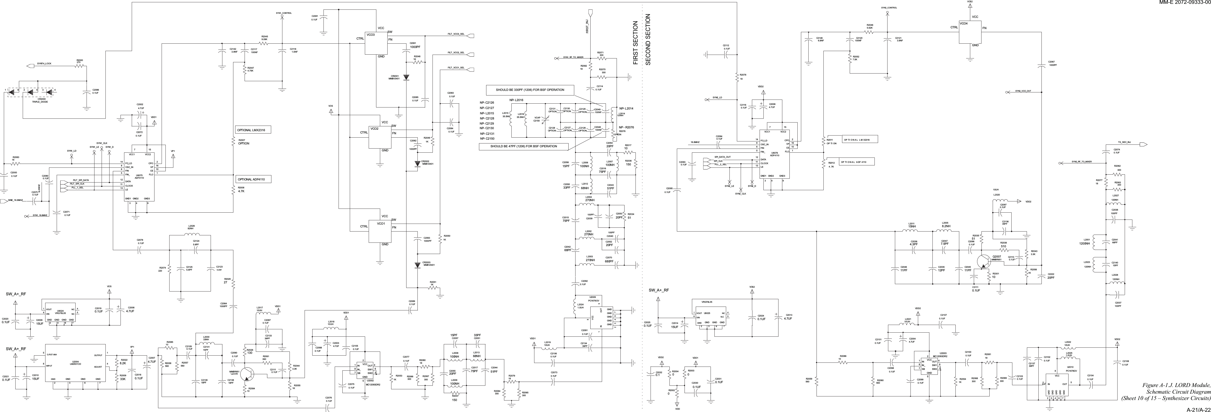
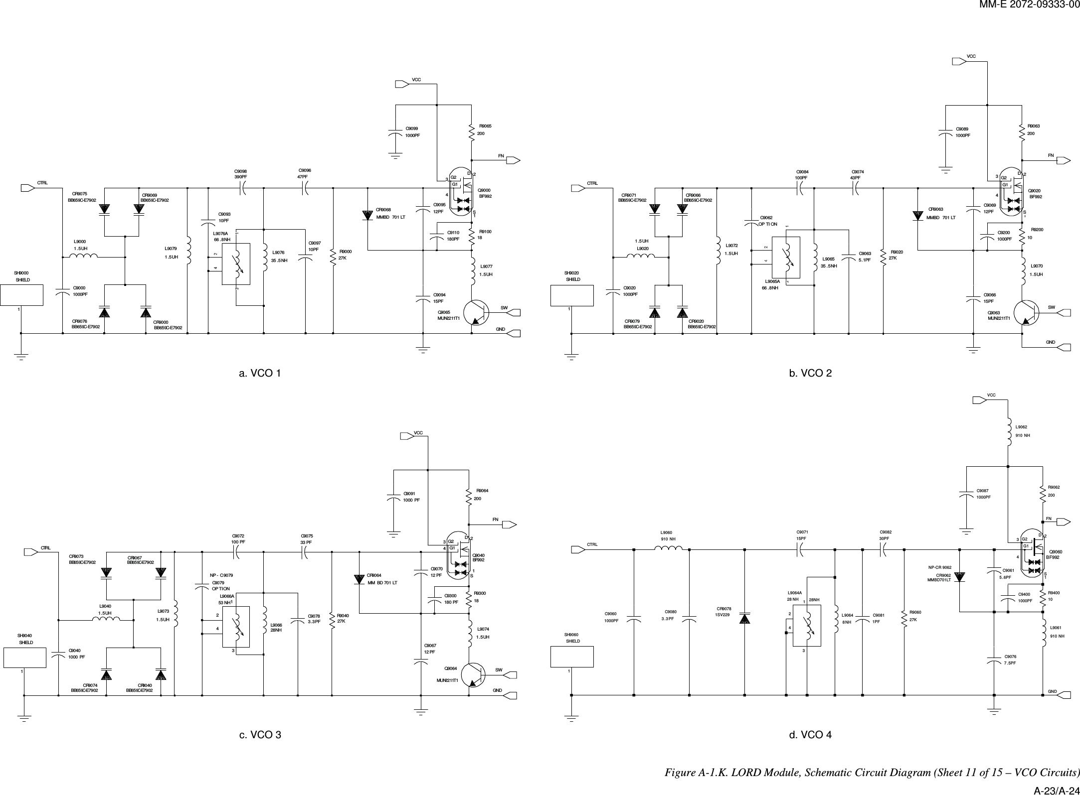
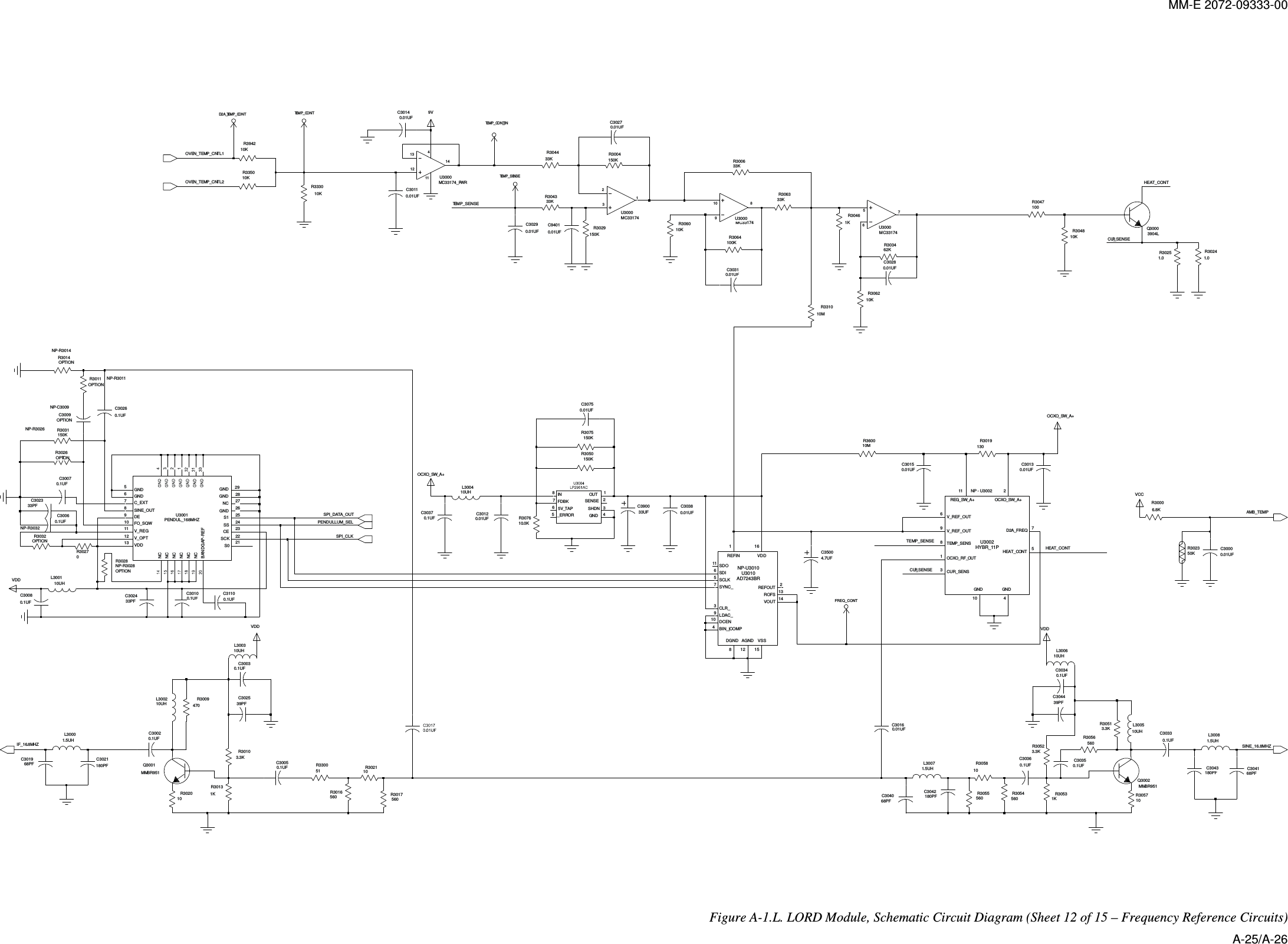
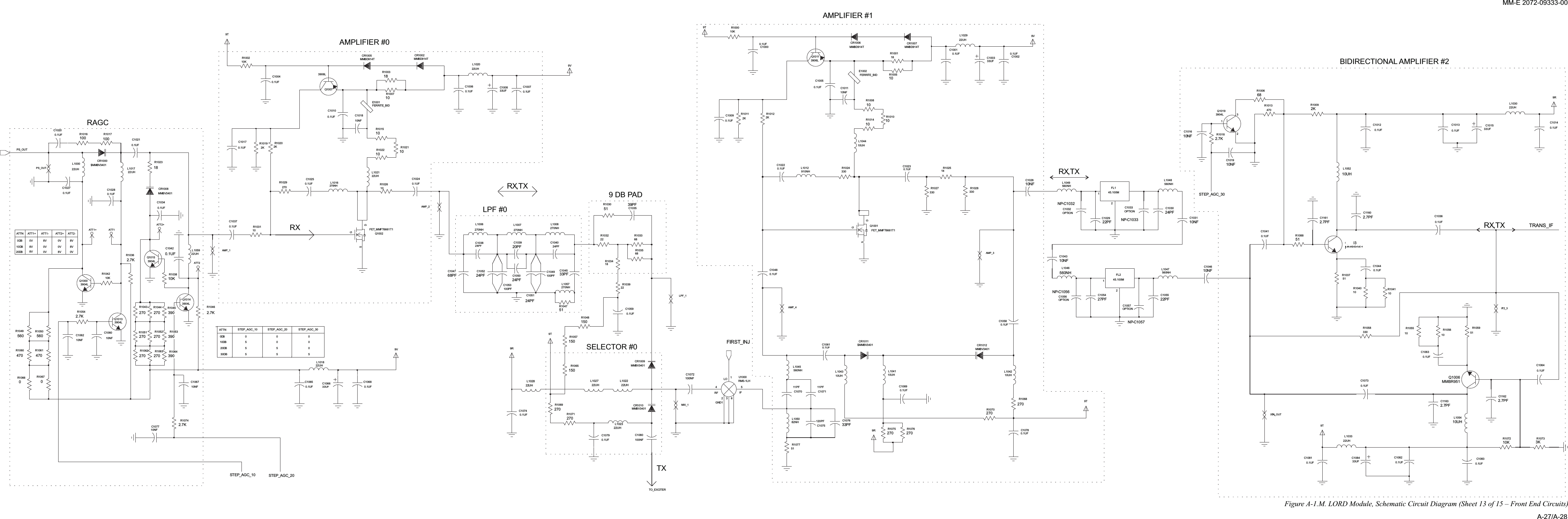
Elbit Systems Land and C4I Tadiran MICOM-TRK125W Licensed Non-Broadcast Station Transmitter - MICOM Z-Trunk User Manual MICOM Z MME fp
Elbit Systems Land and C4I - Tadiran Ltd. Licensed Non-Broadcast Station Transmitter - MICOM Z-Trunk MICOM Z MME fp
Contents
- 1. Operators Manual
- 2. Service Manual
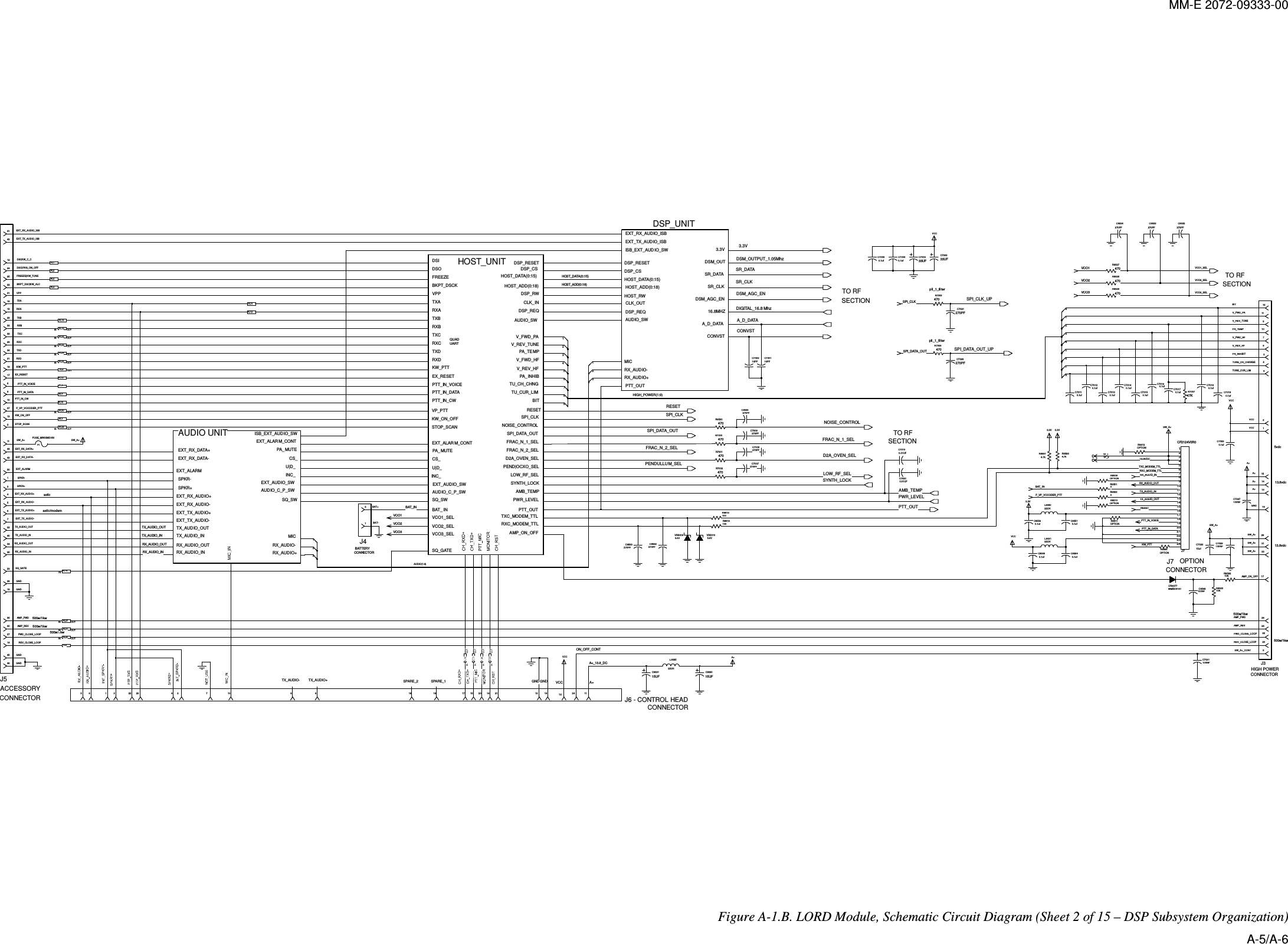
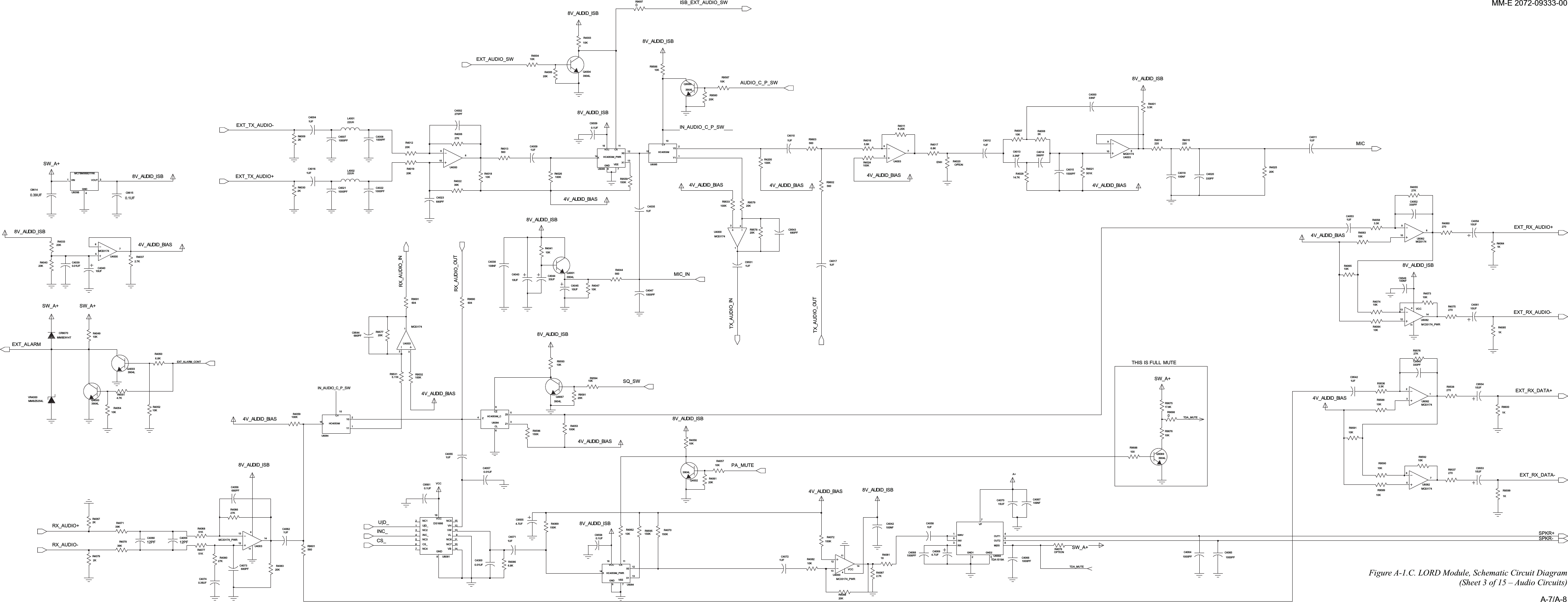
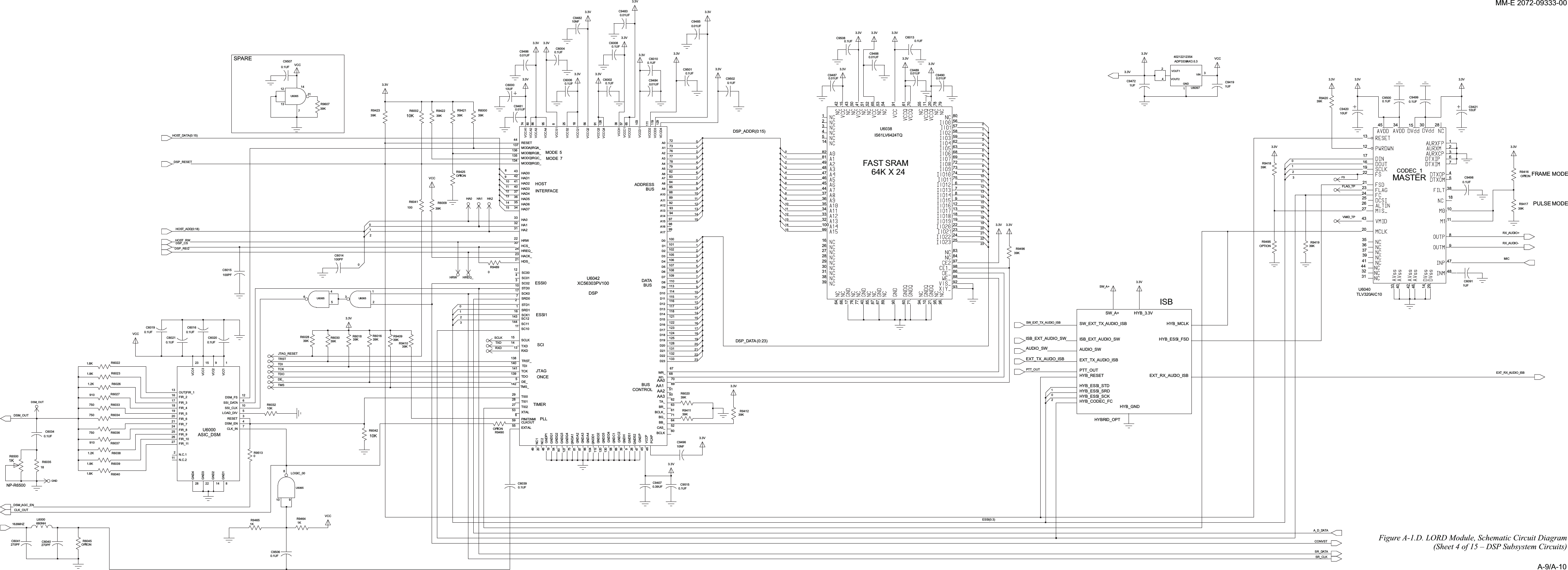
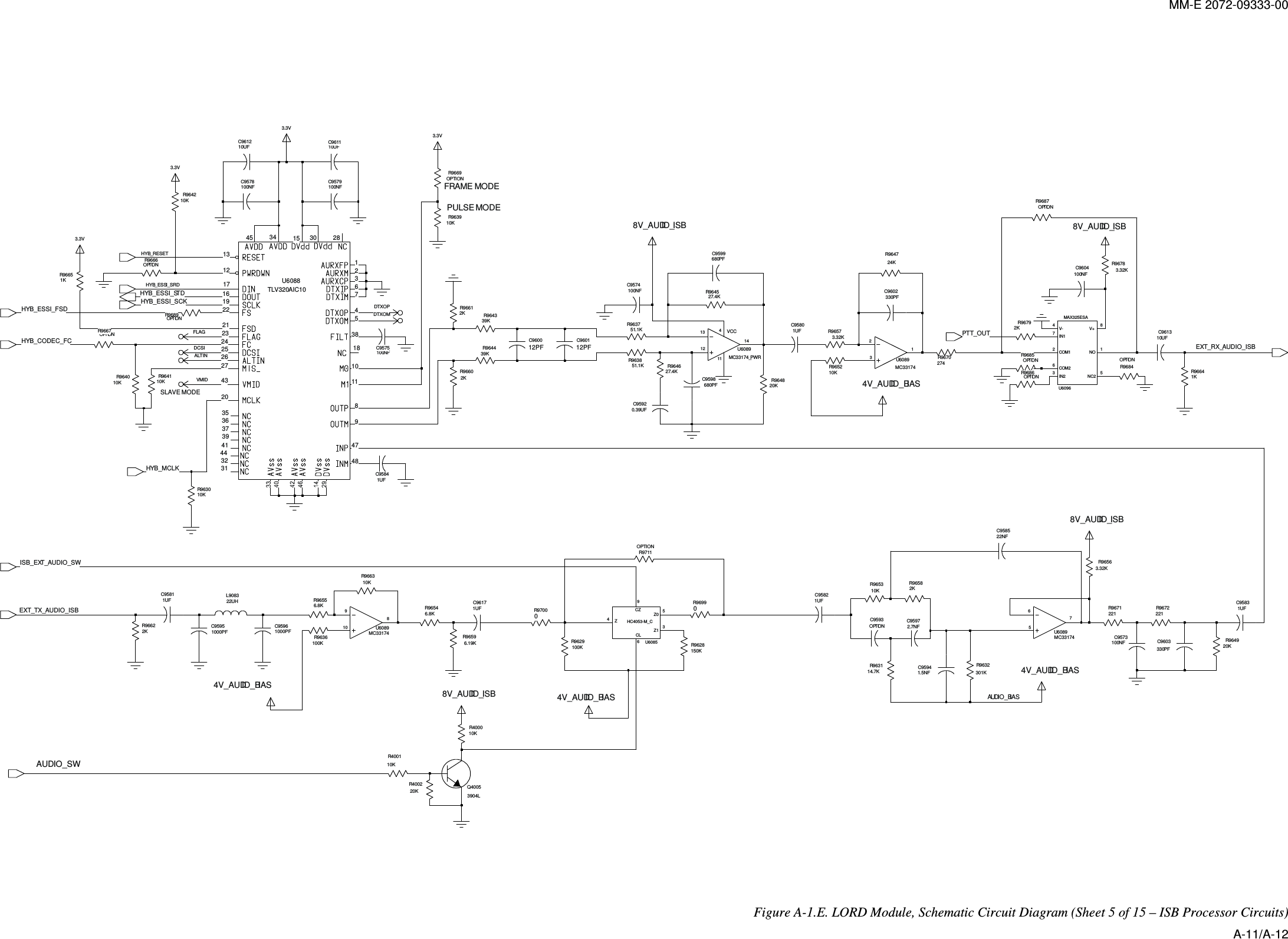
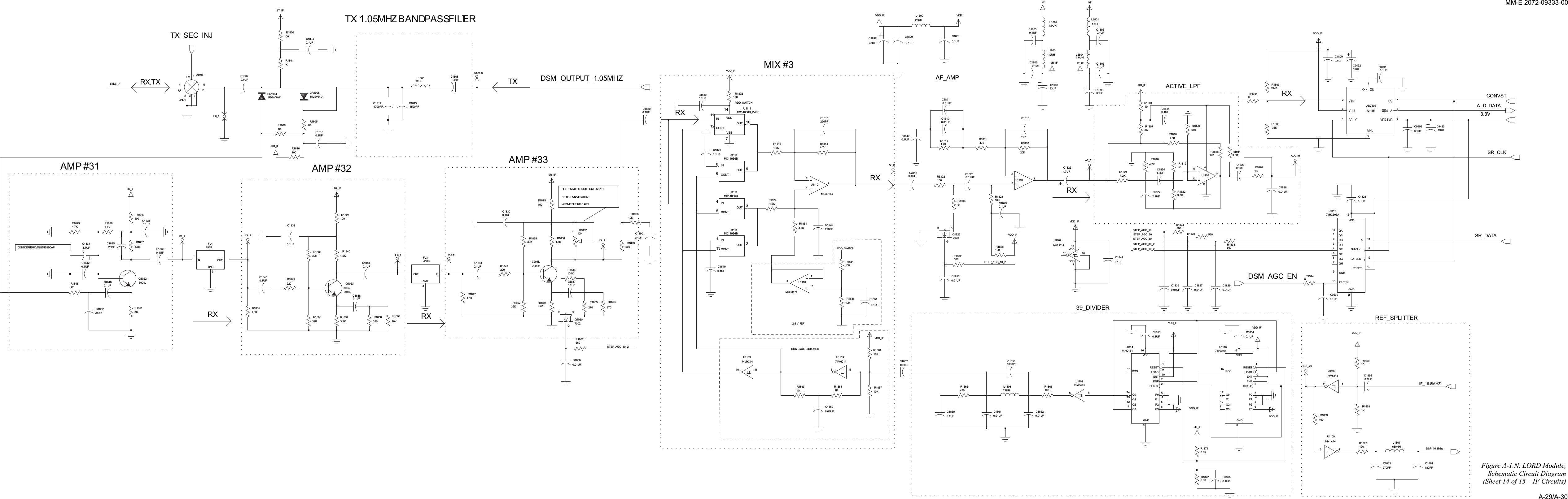
Service Manual

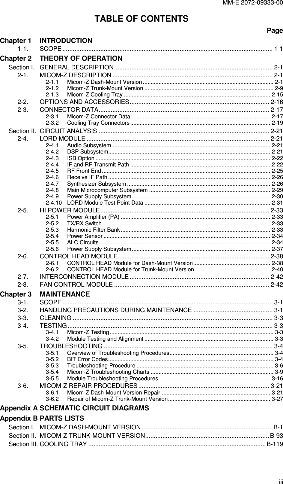
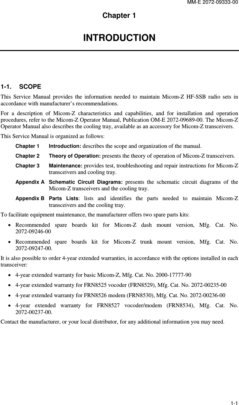
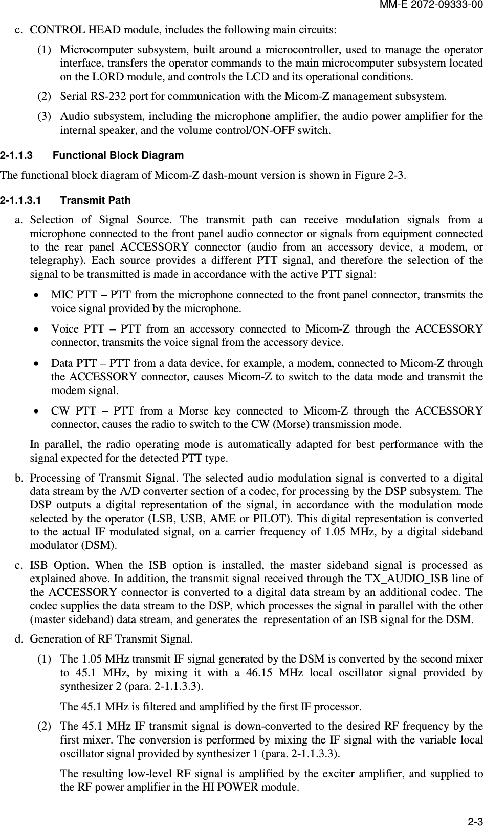
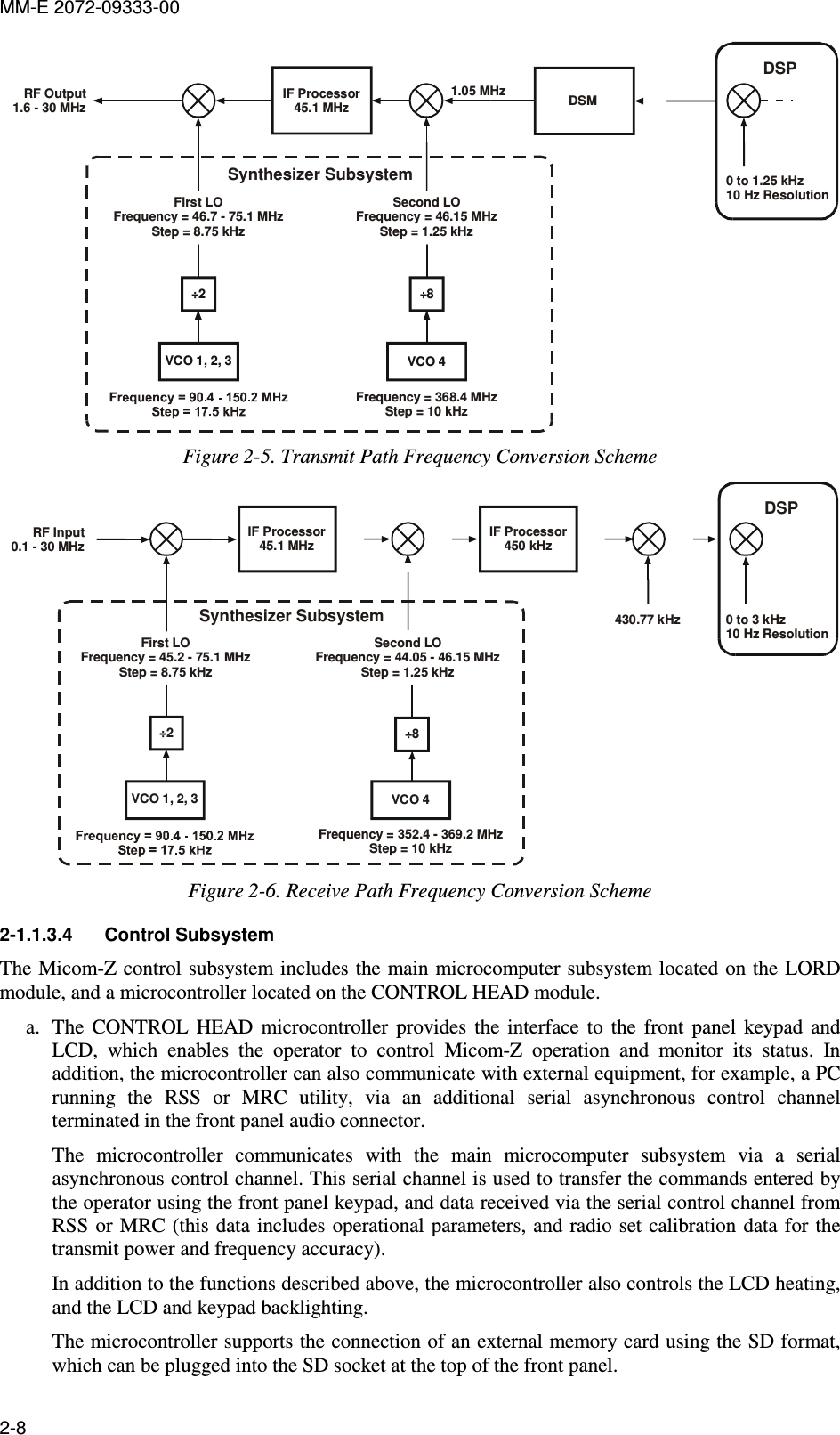
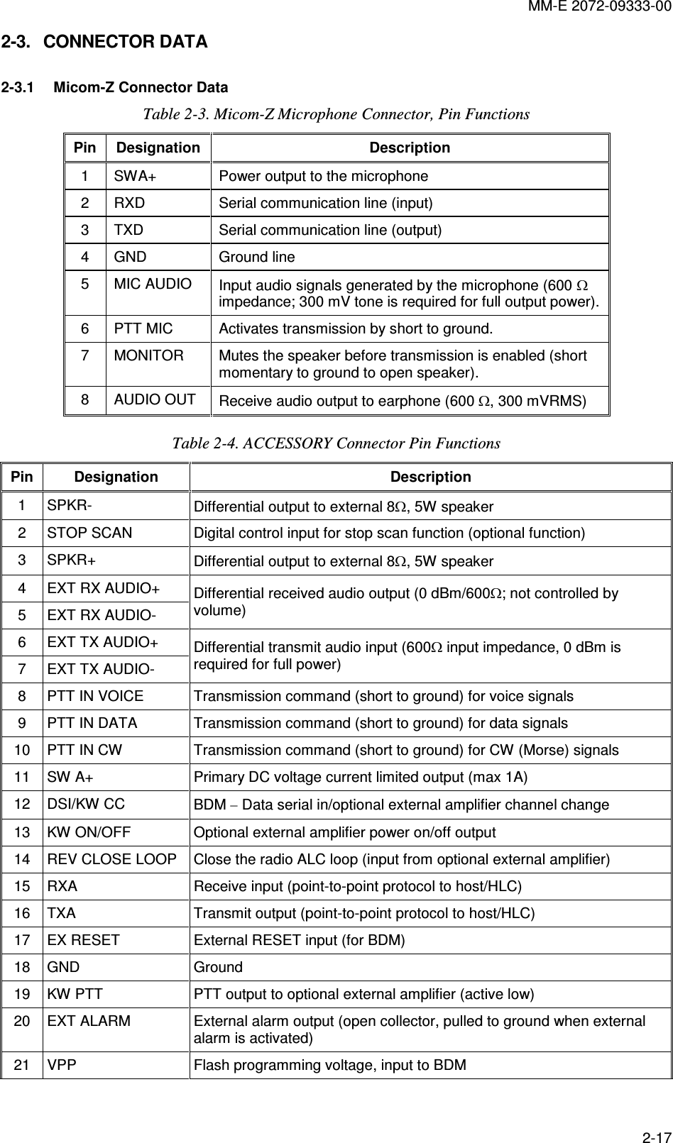
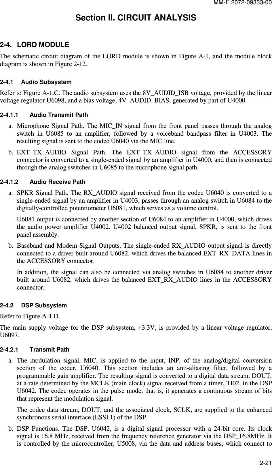
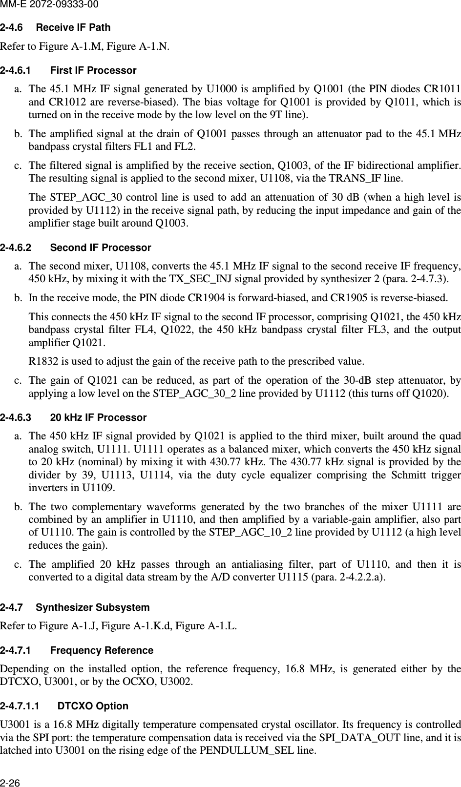
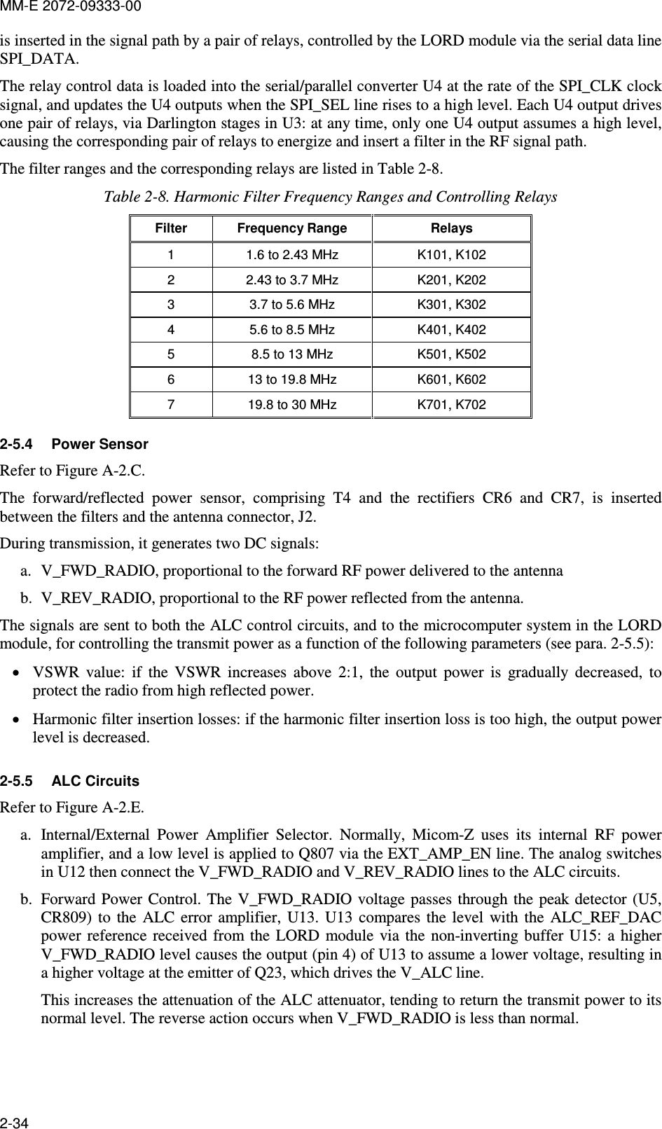
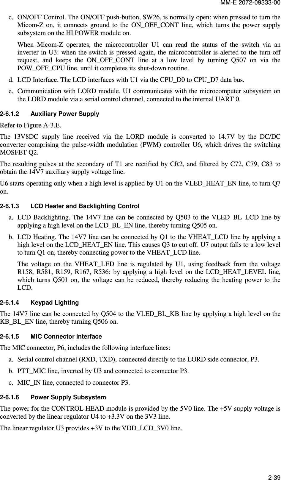
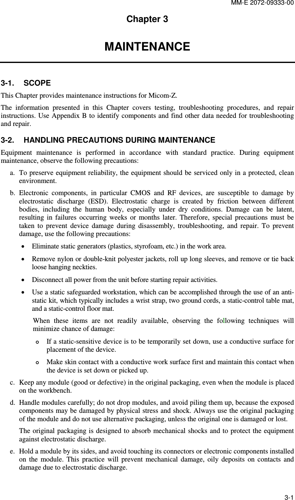
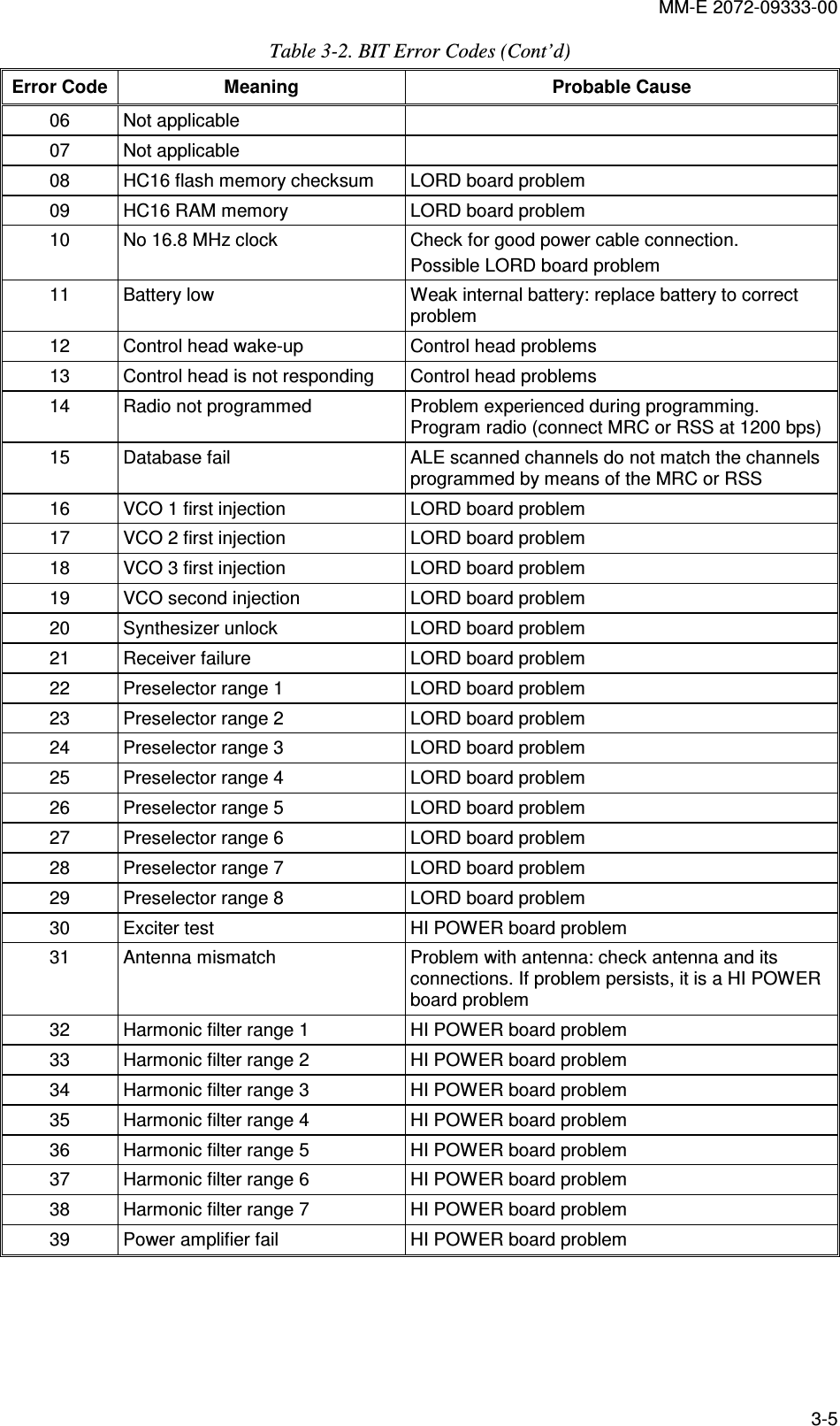
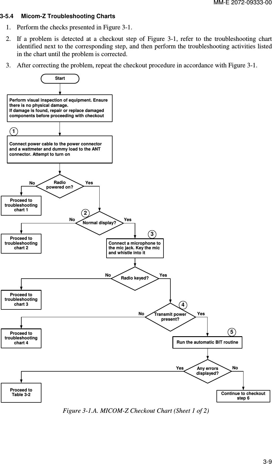
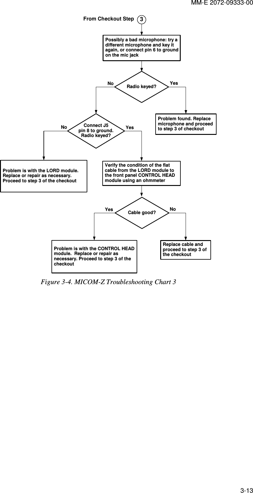
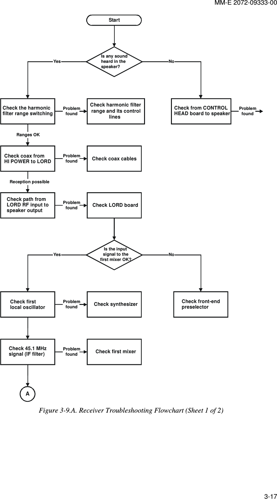
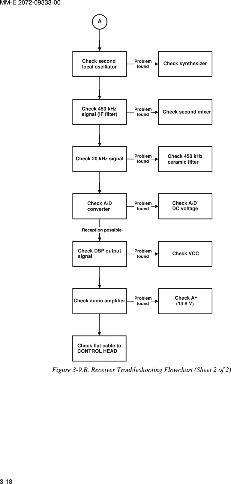
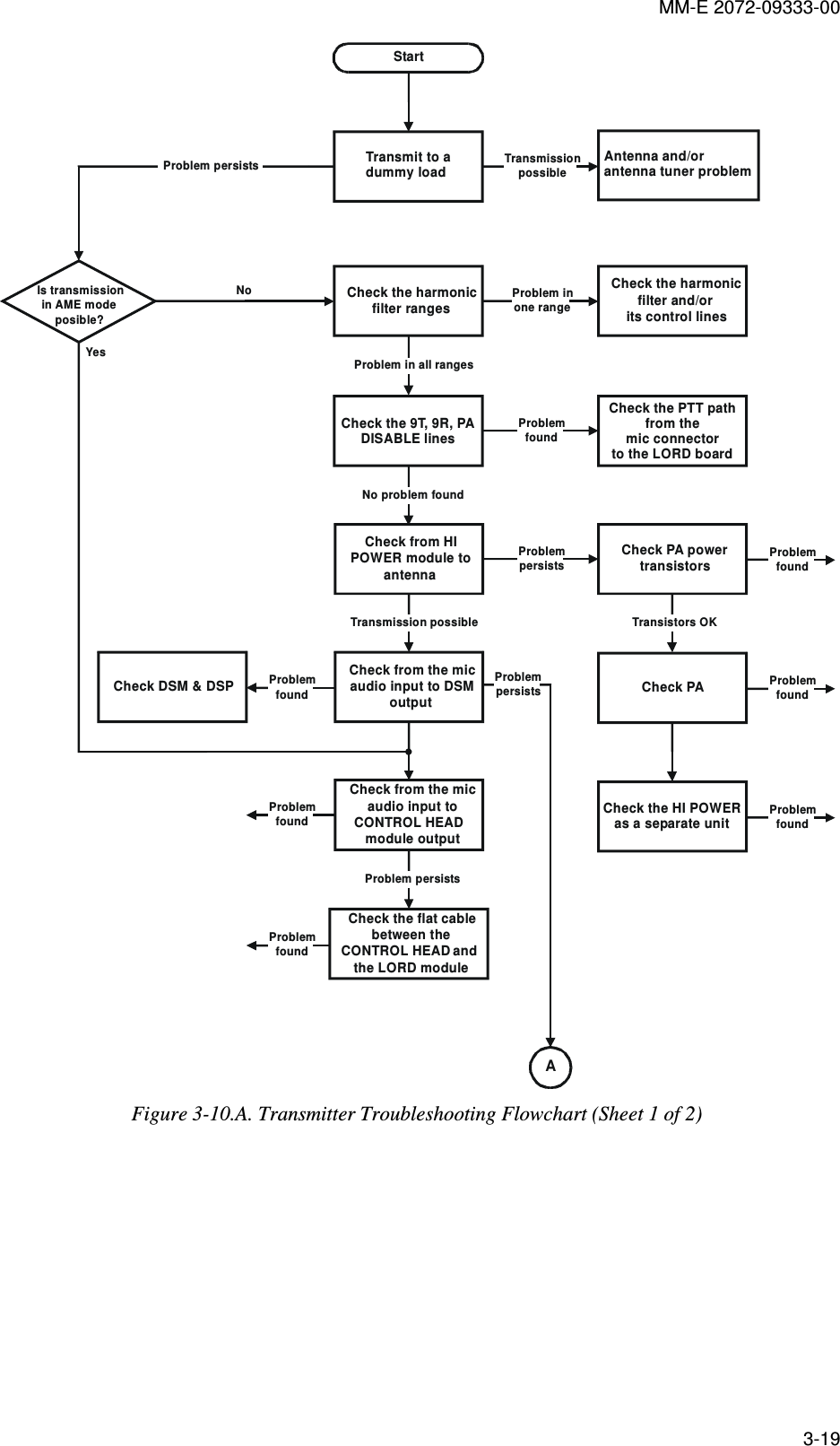
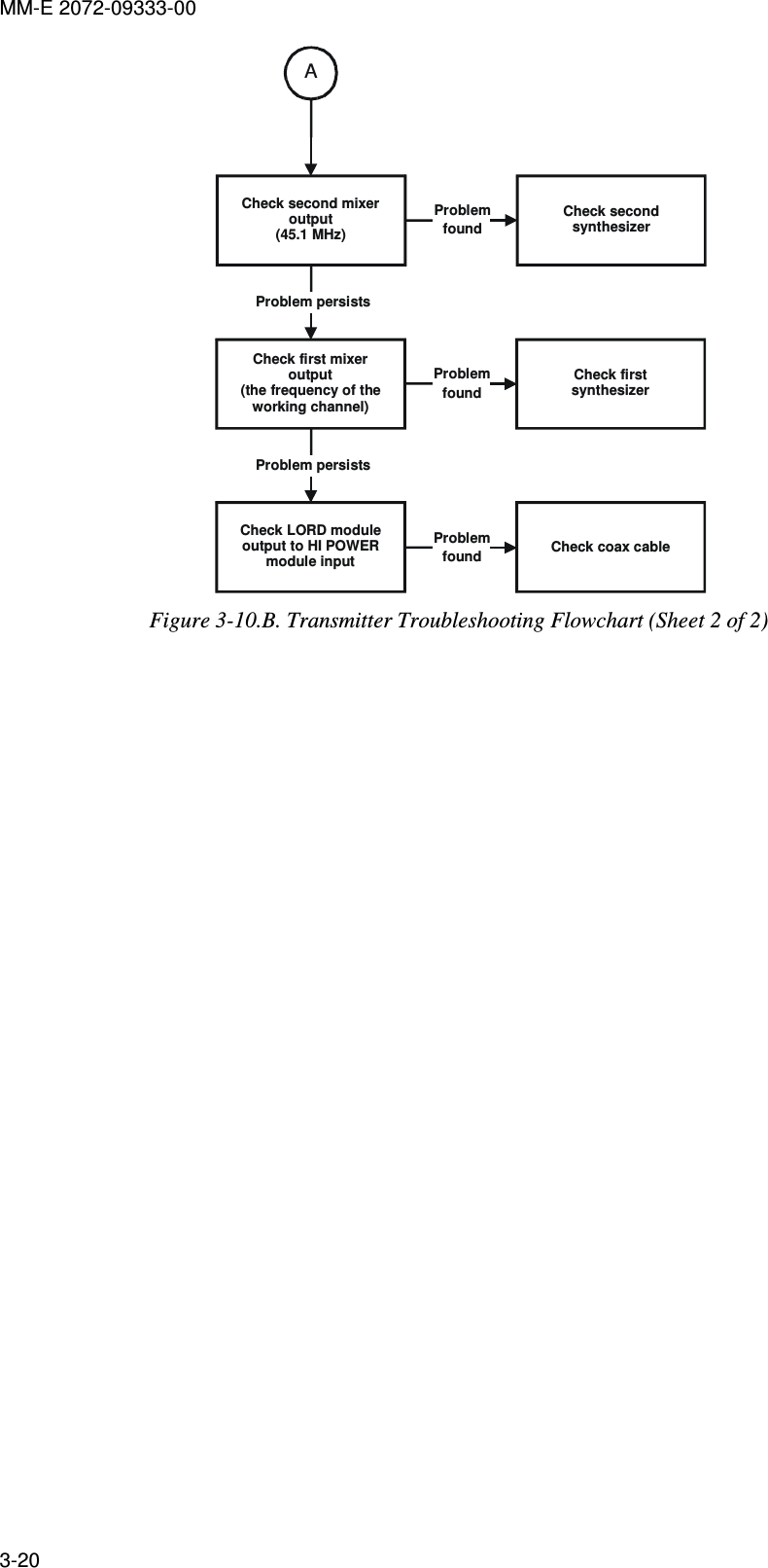
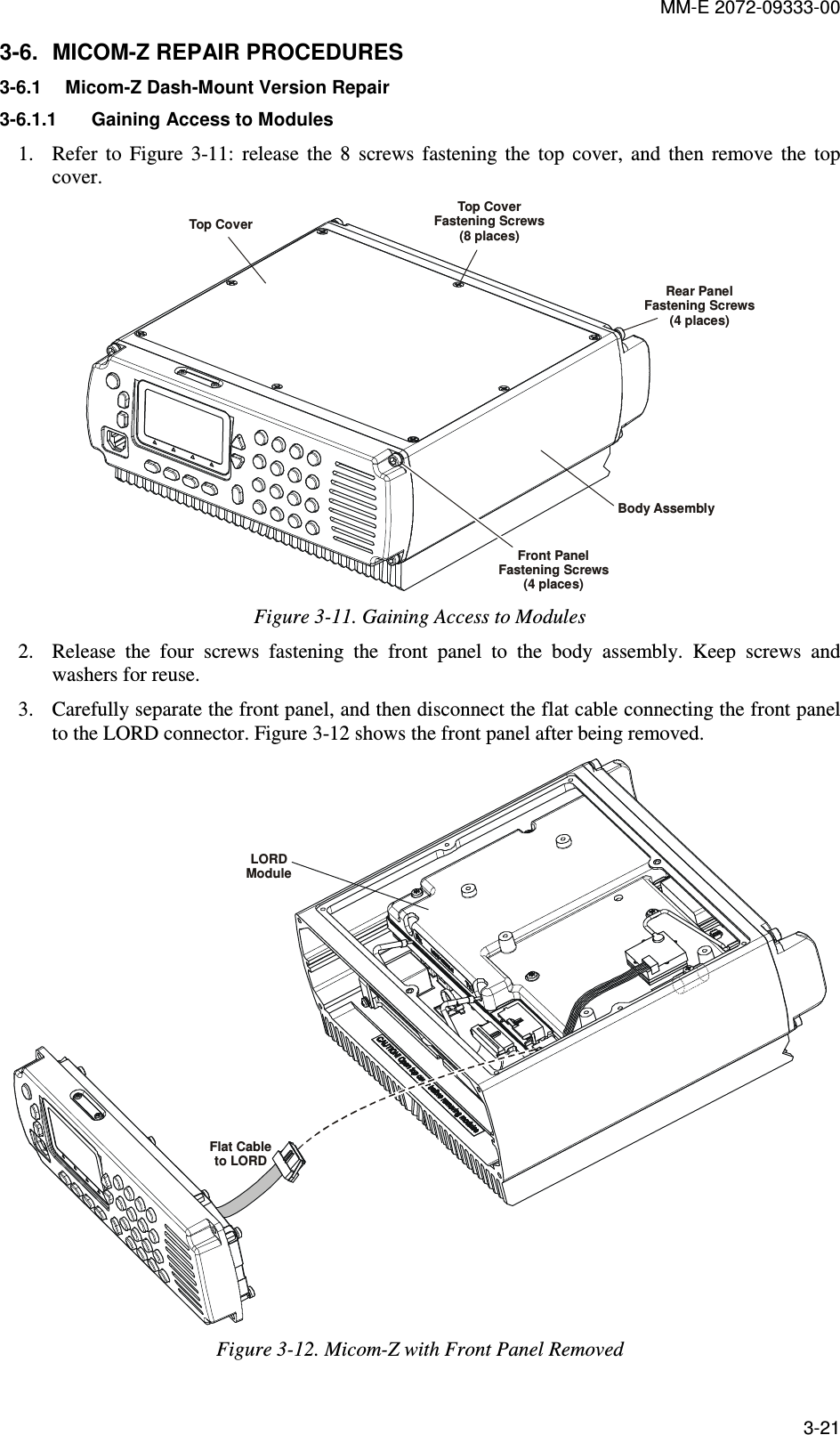
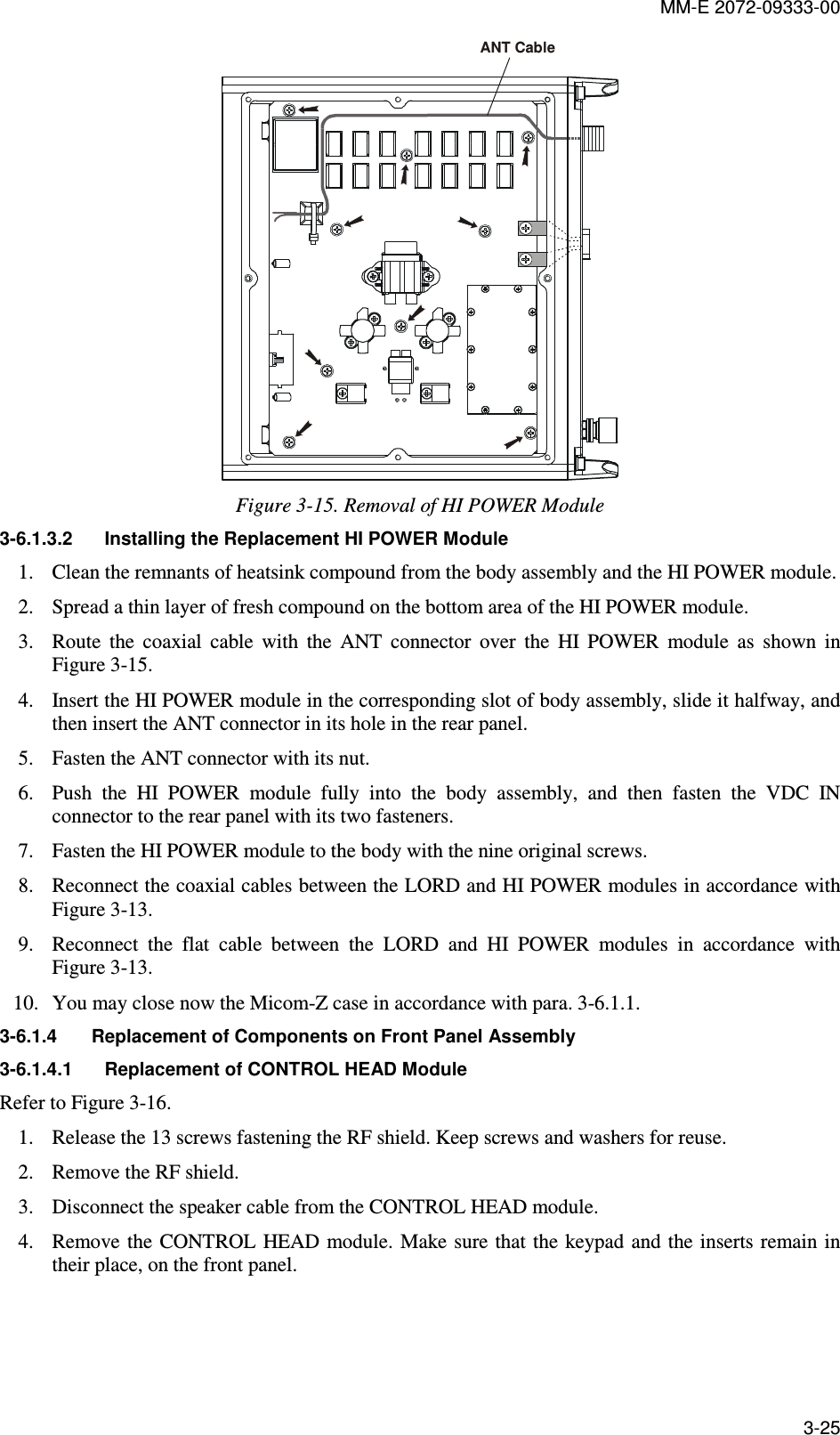
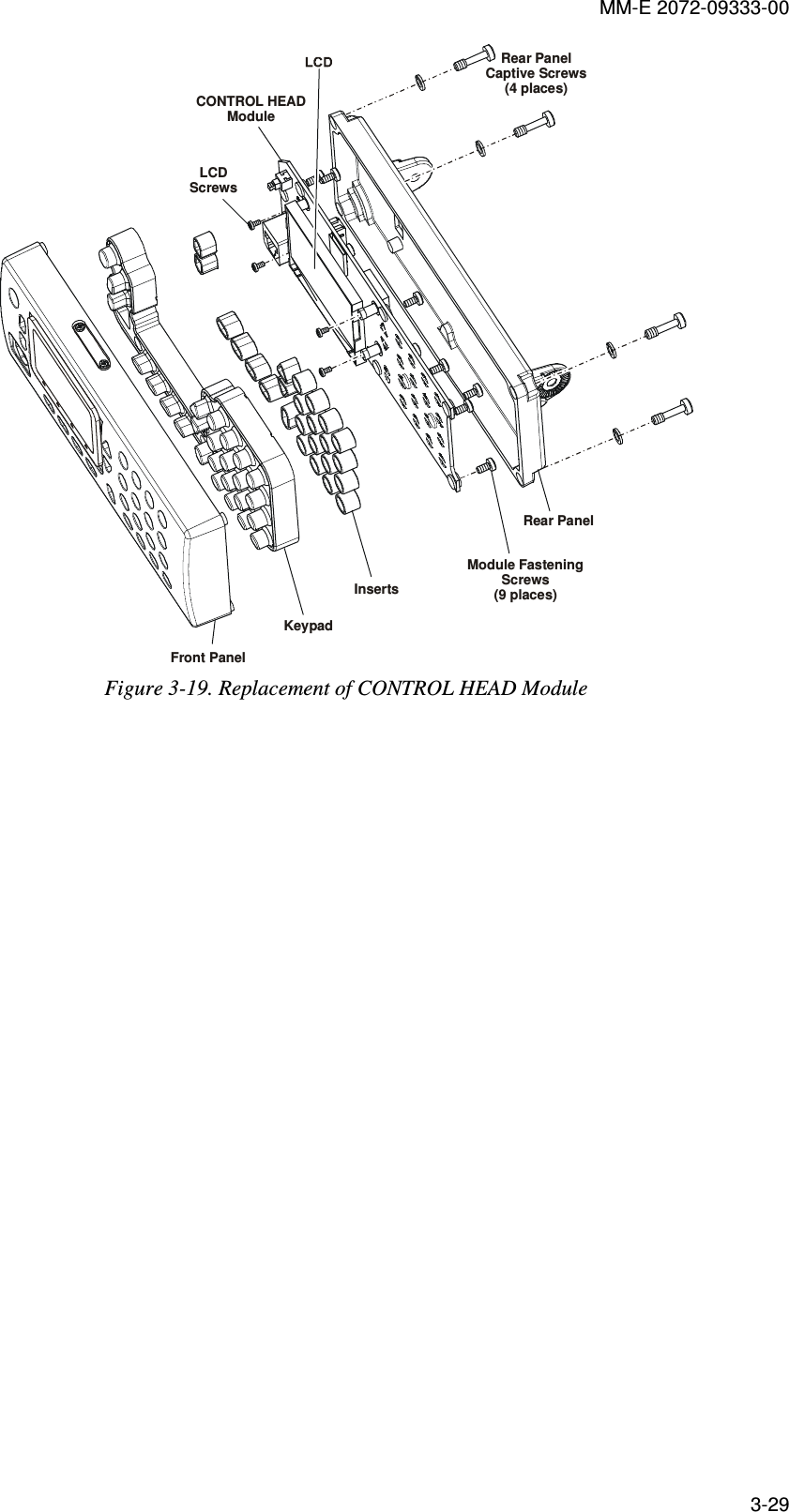

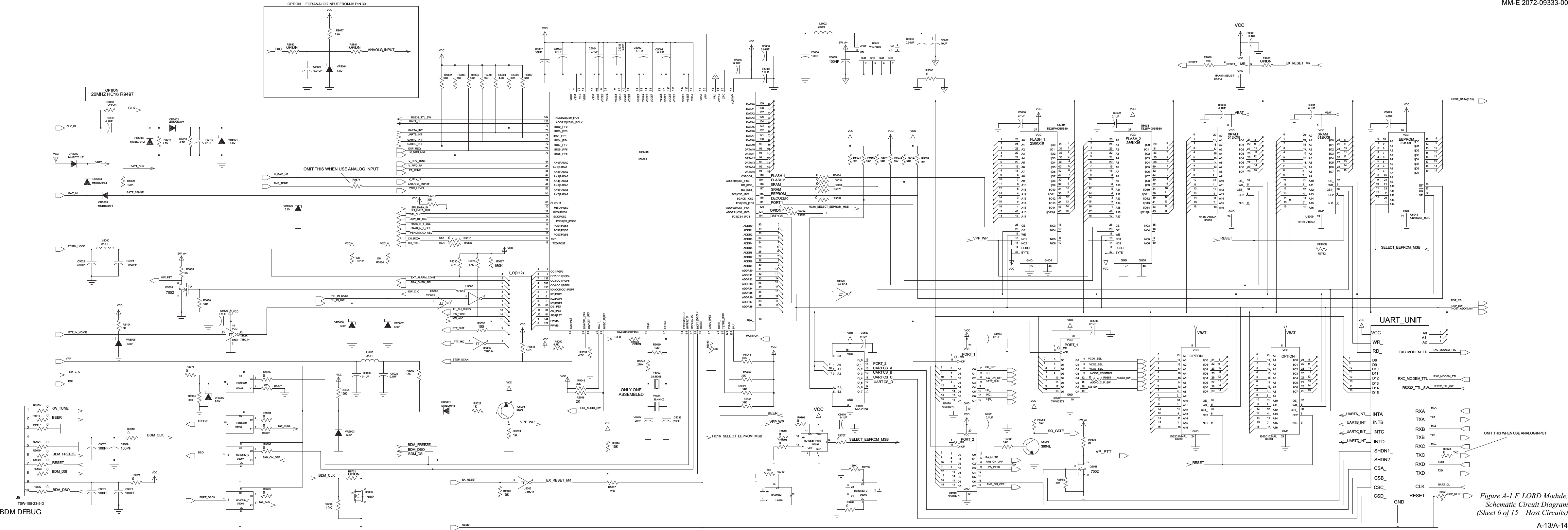
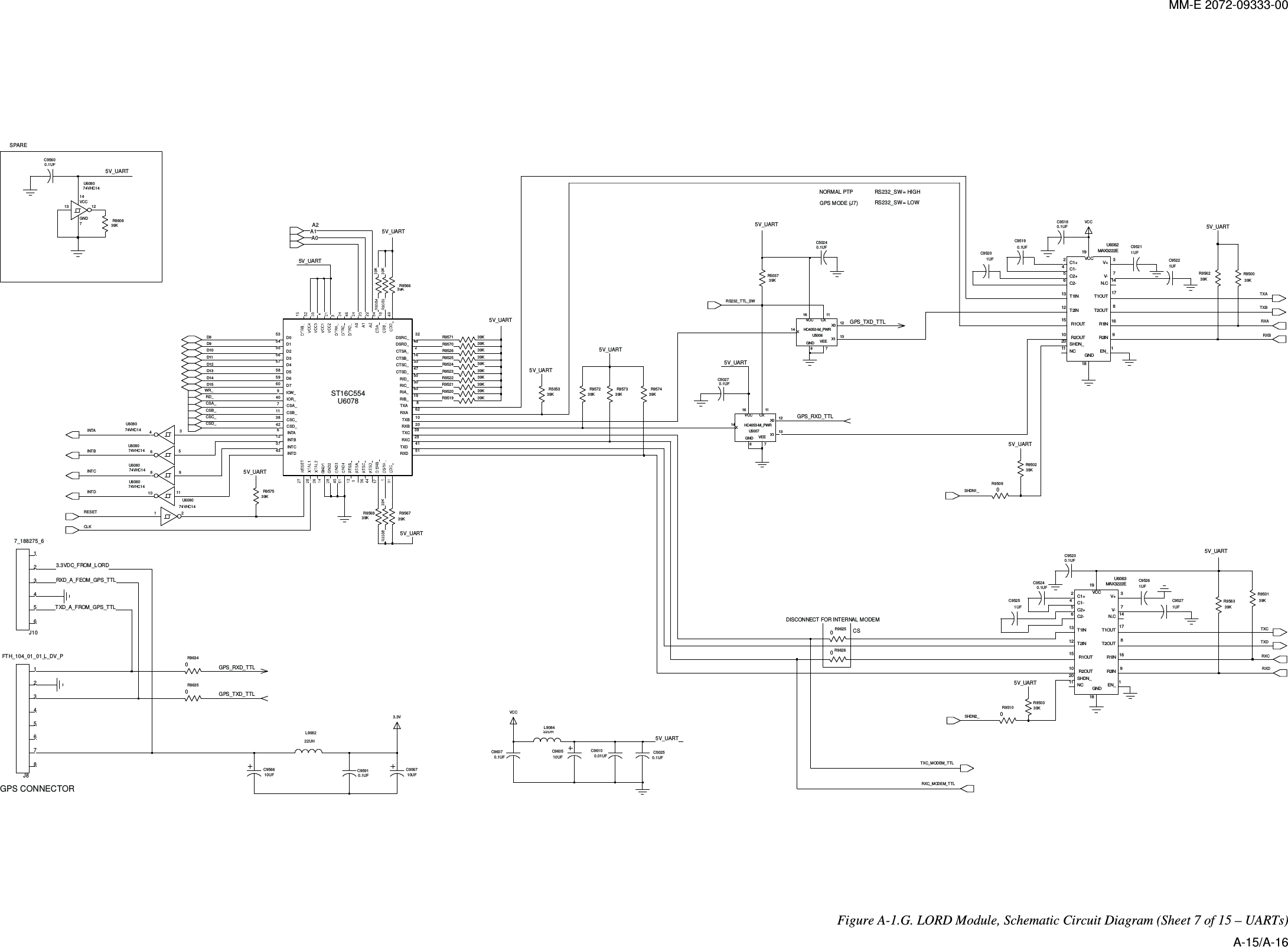
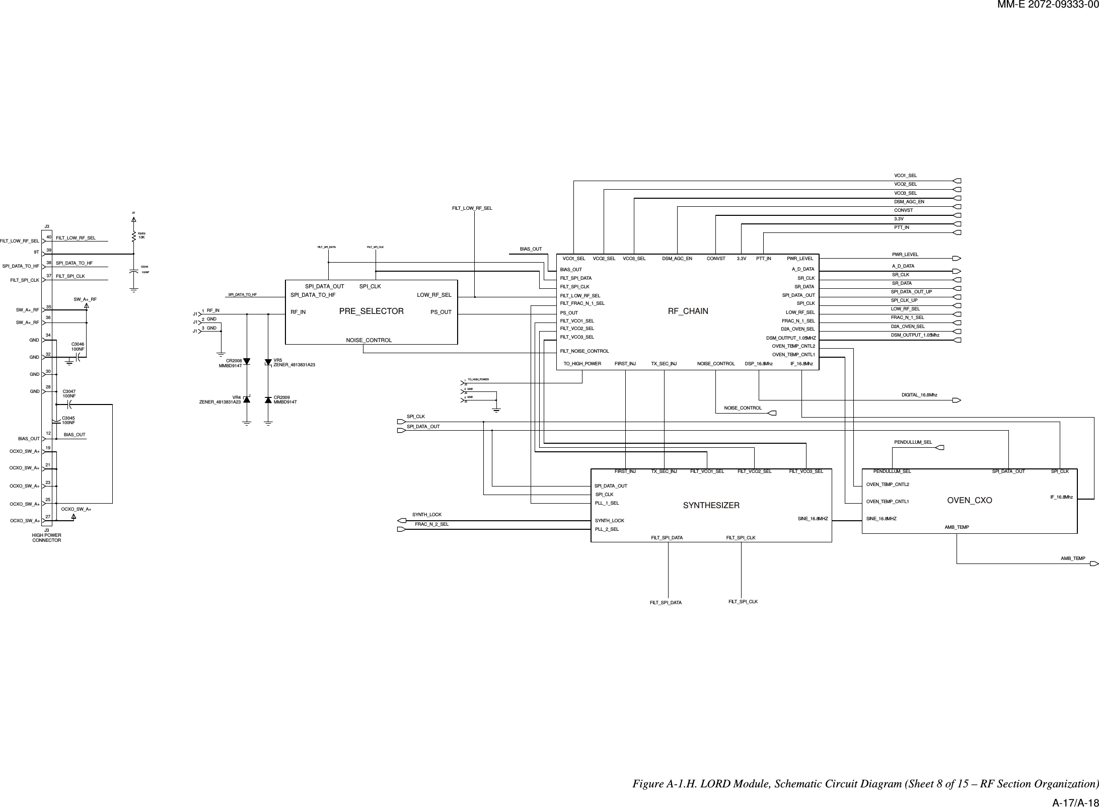
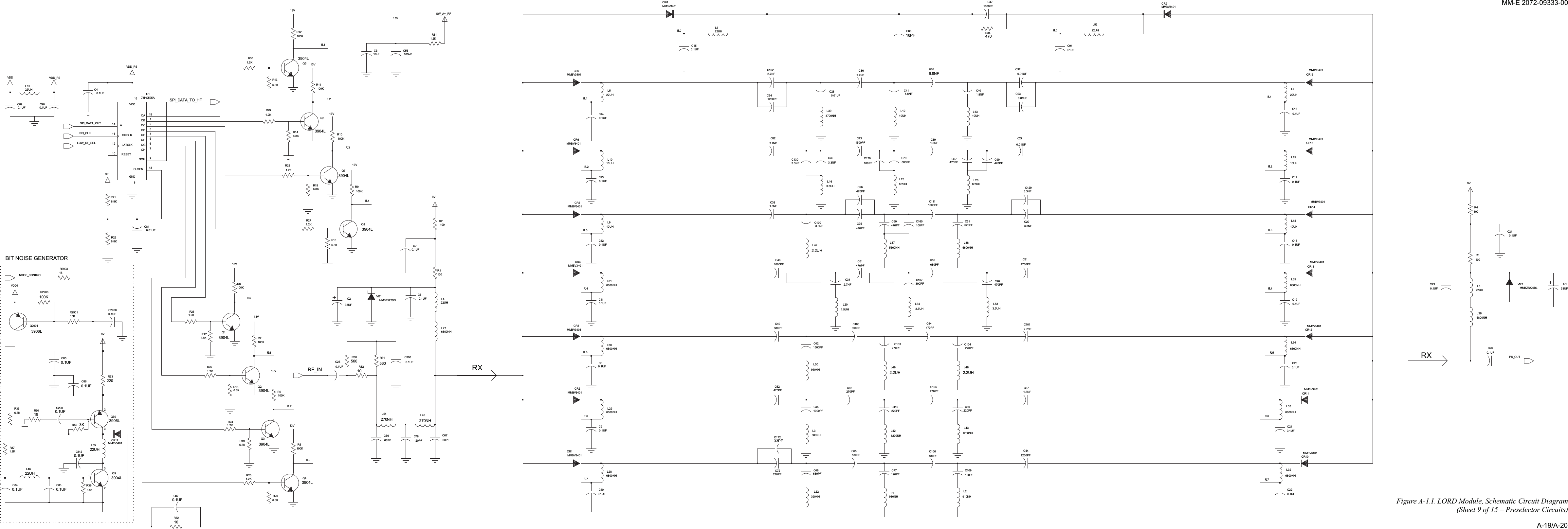
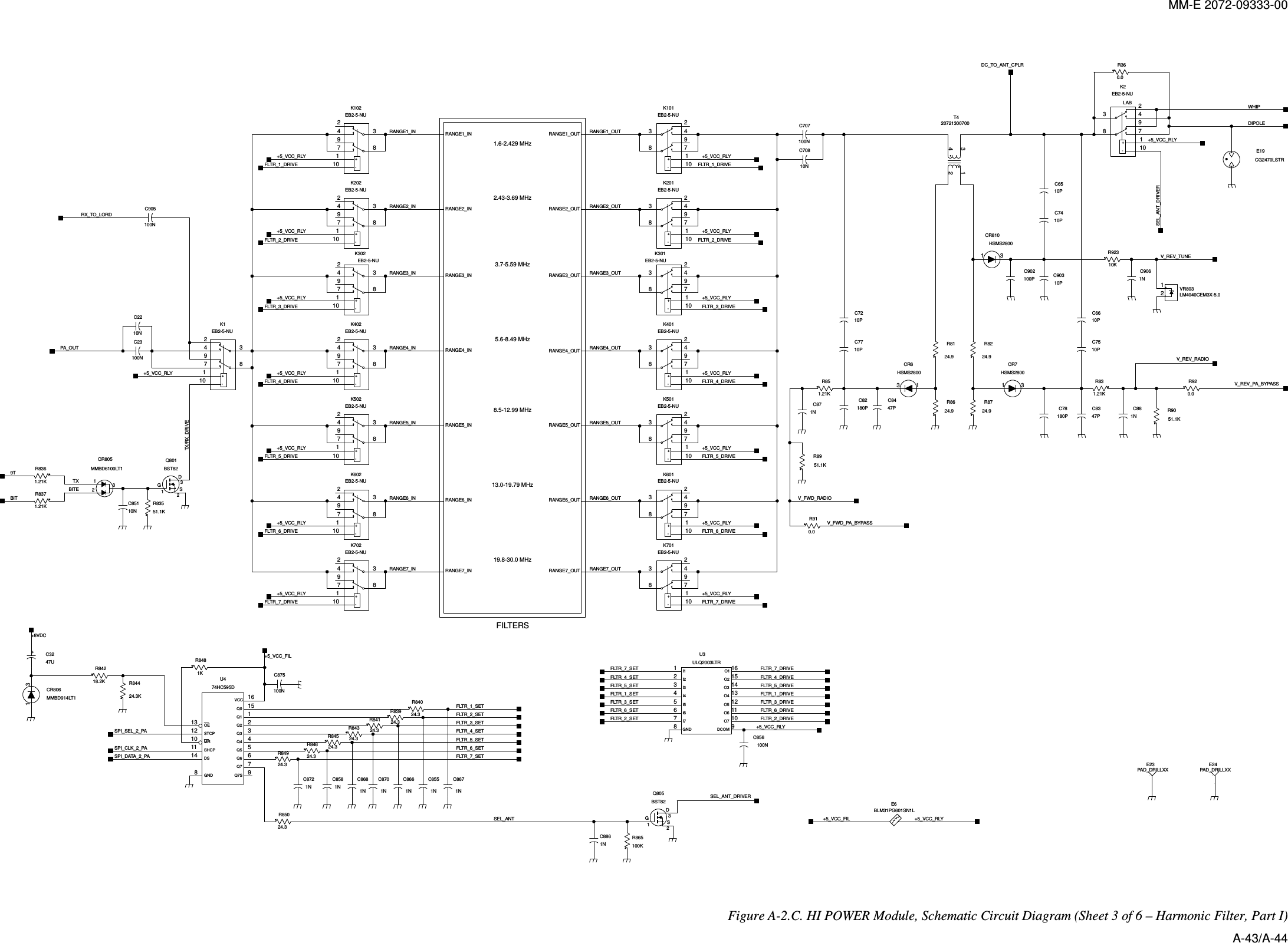
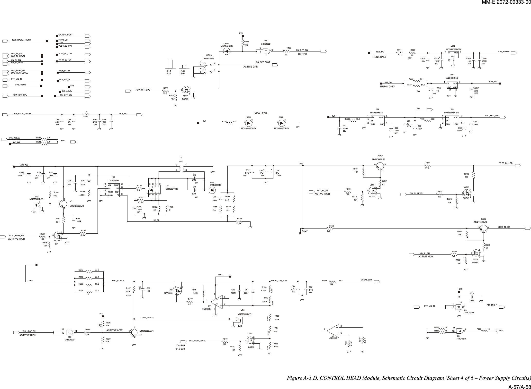
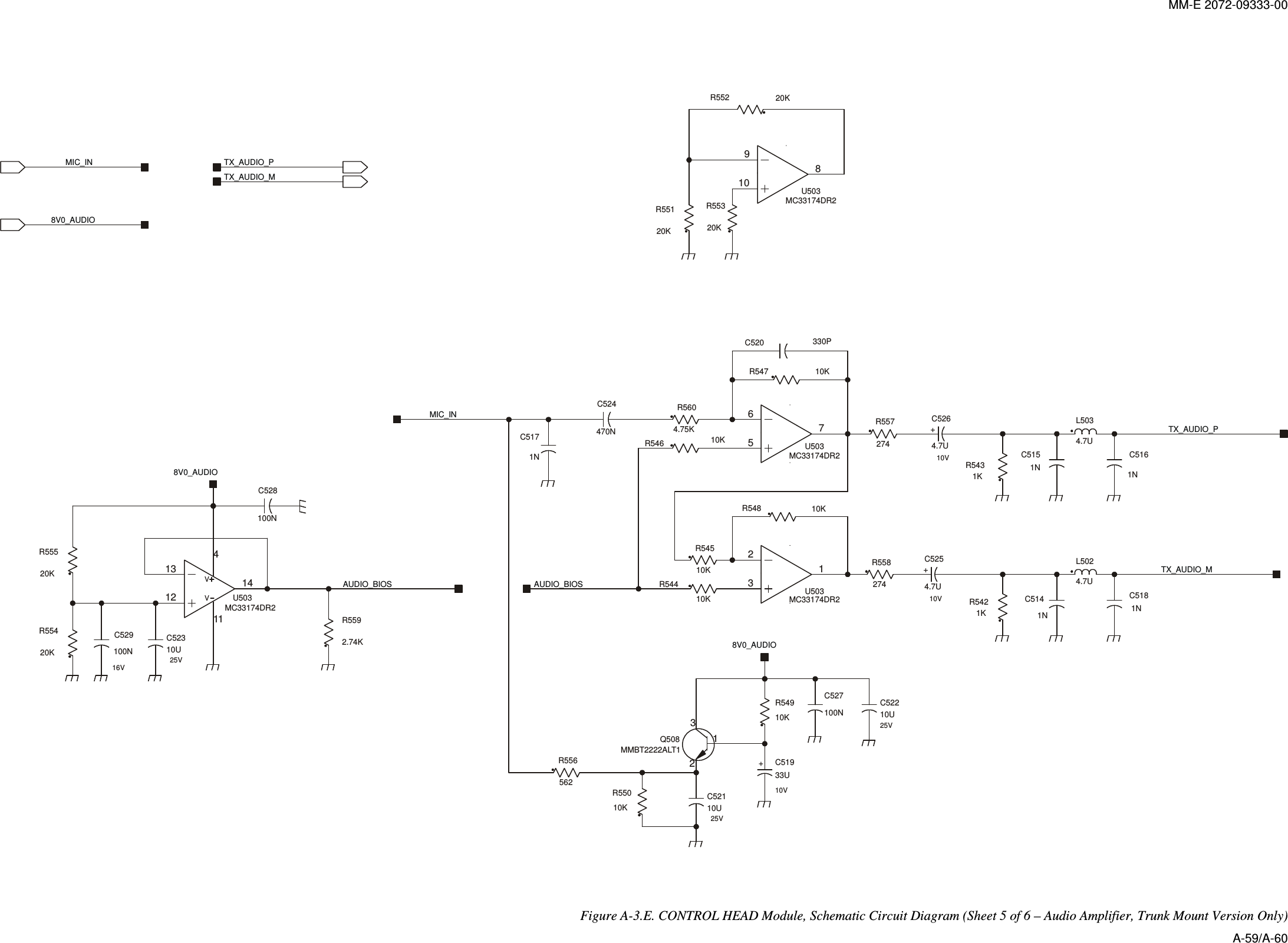
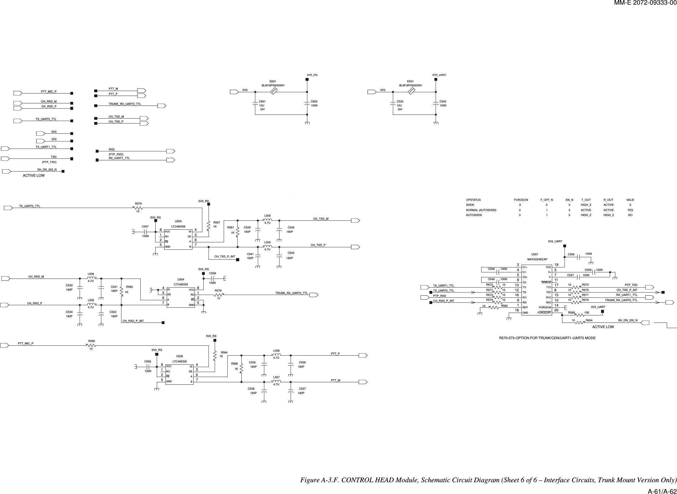
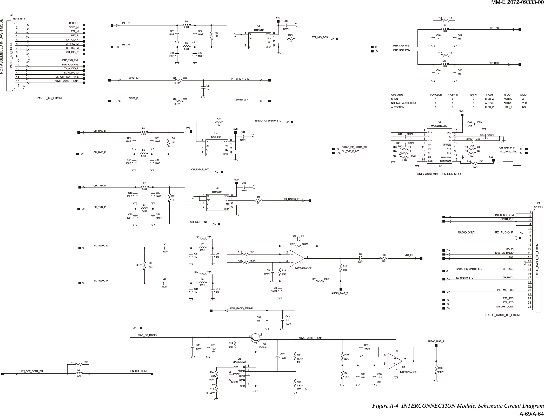
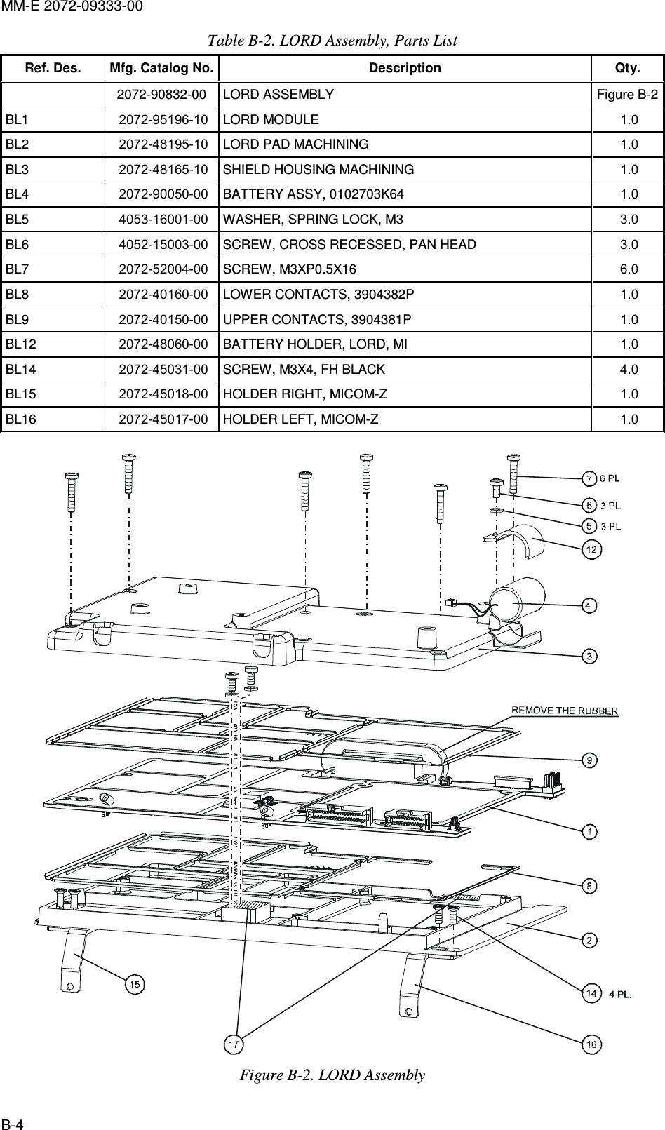
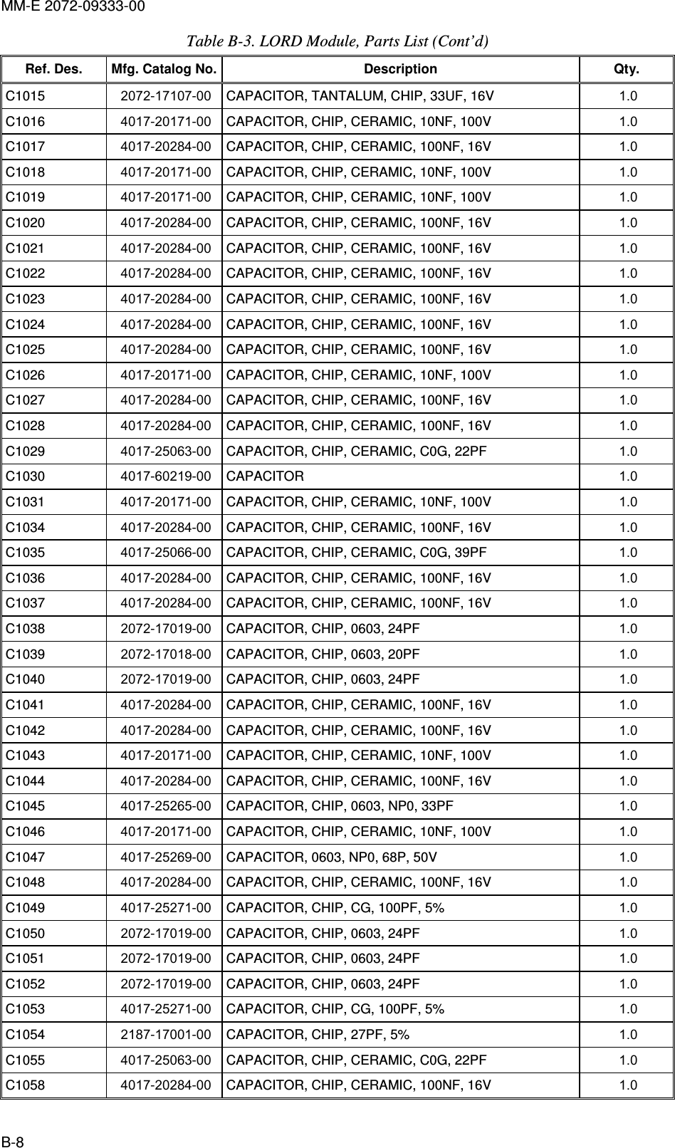
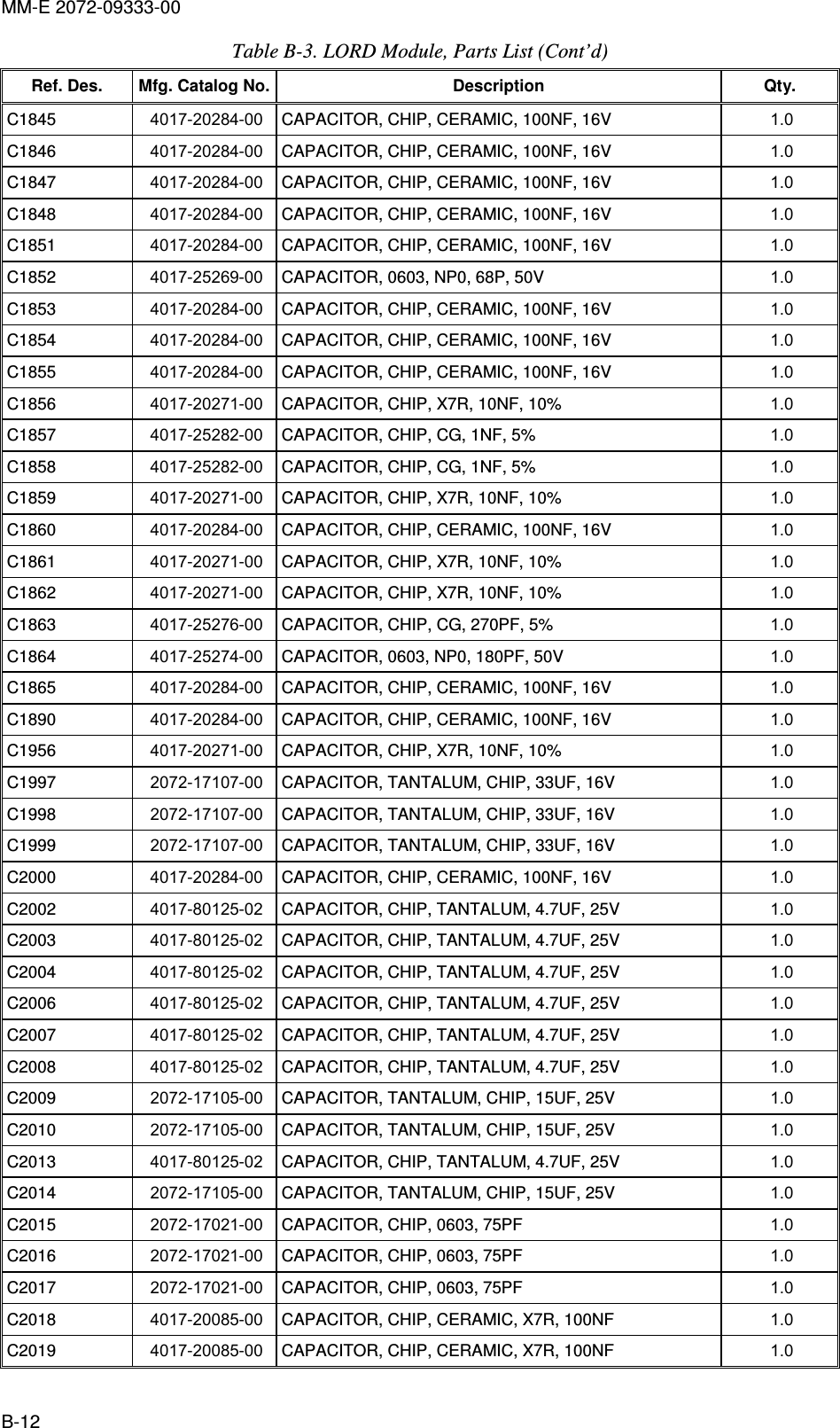
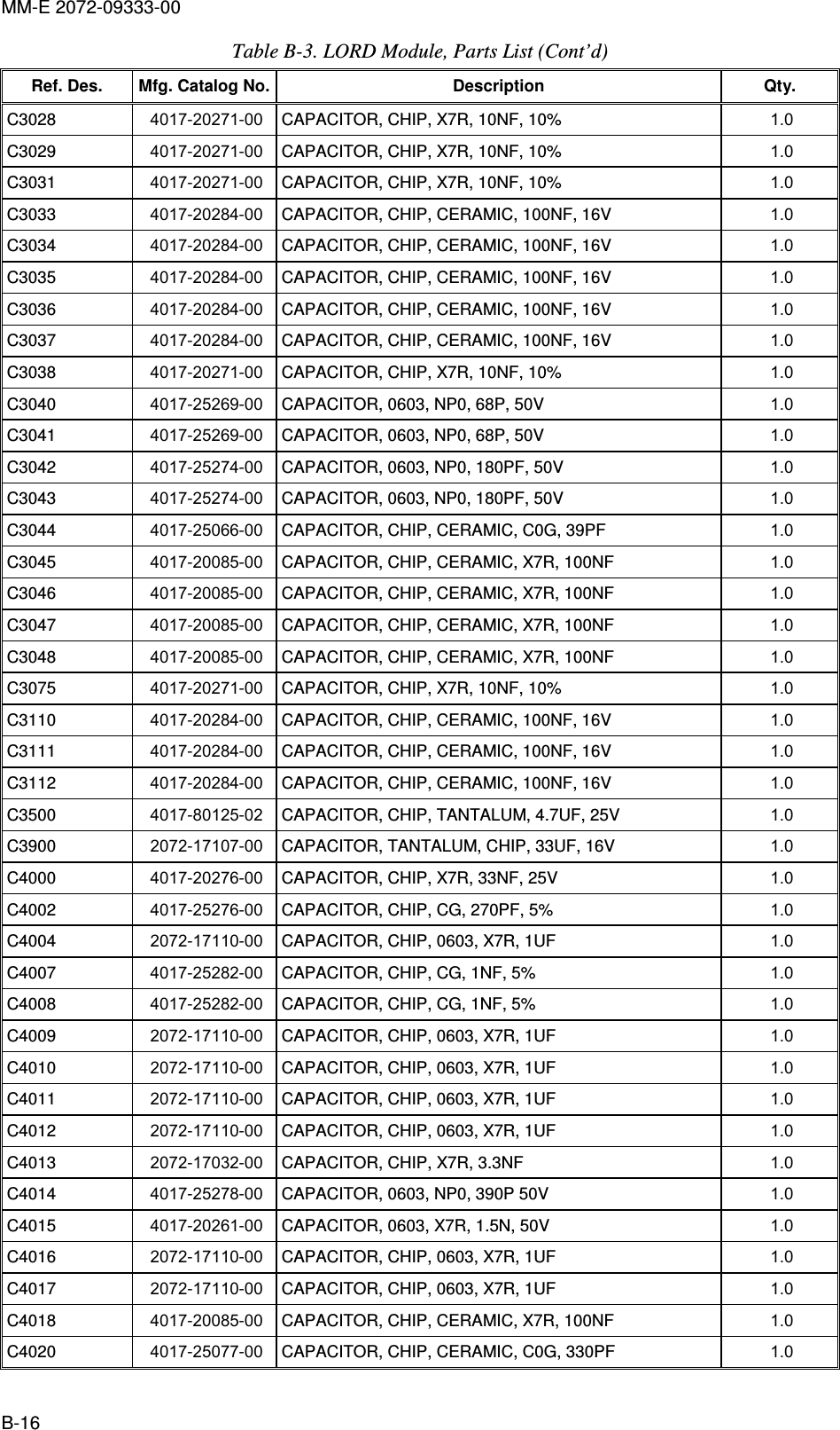
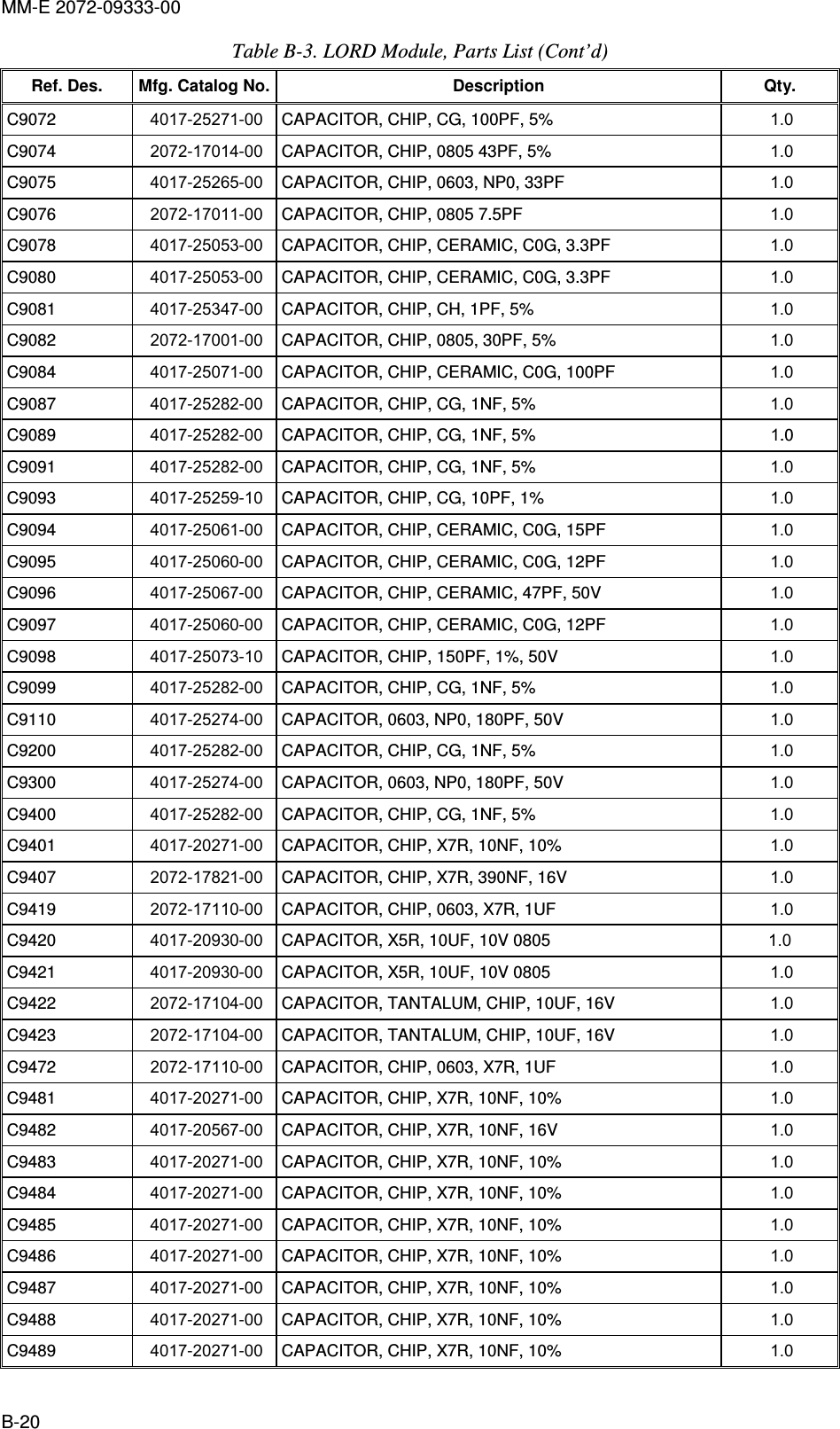
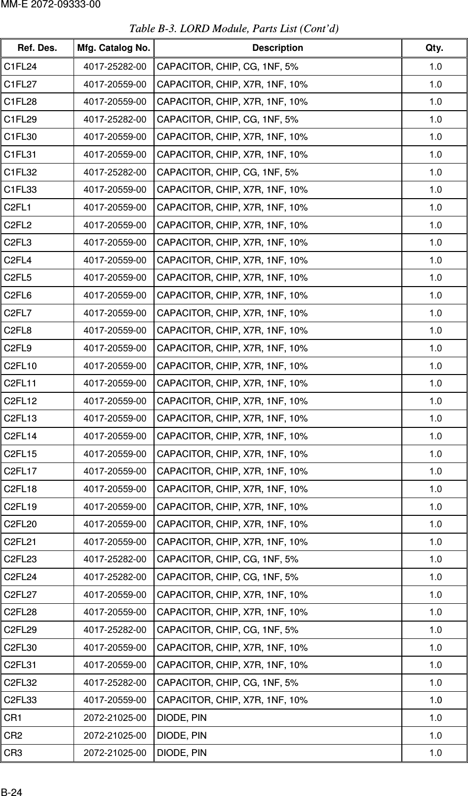
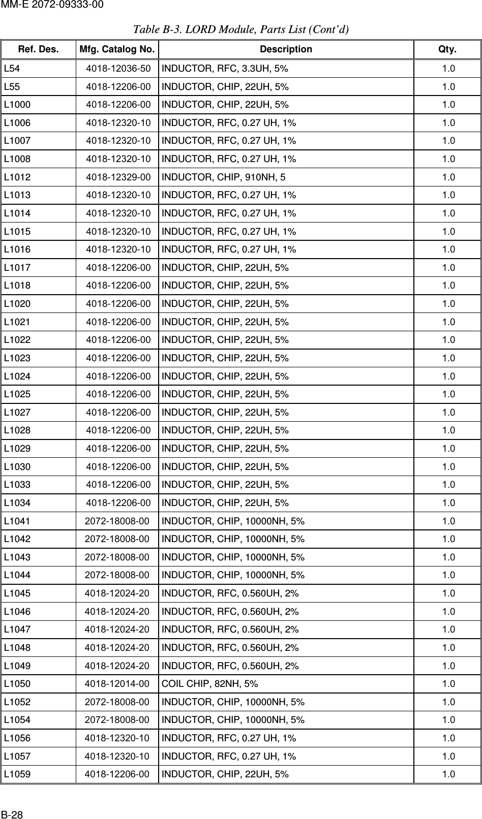
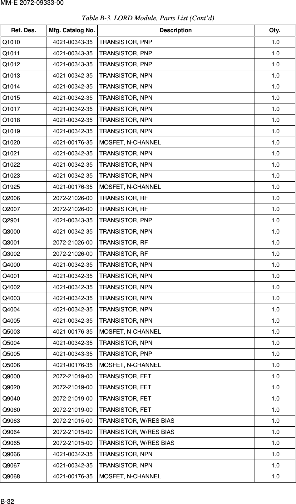
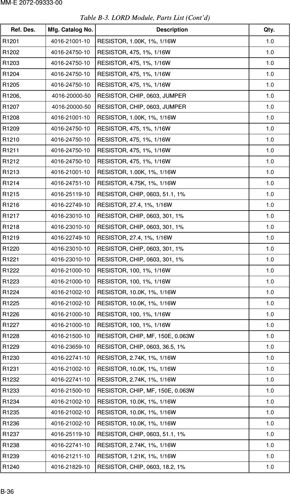
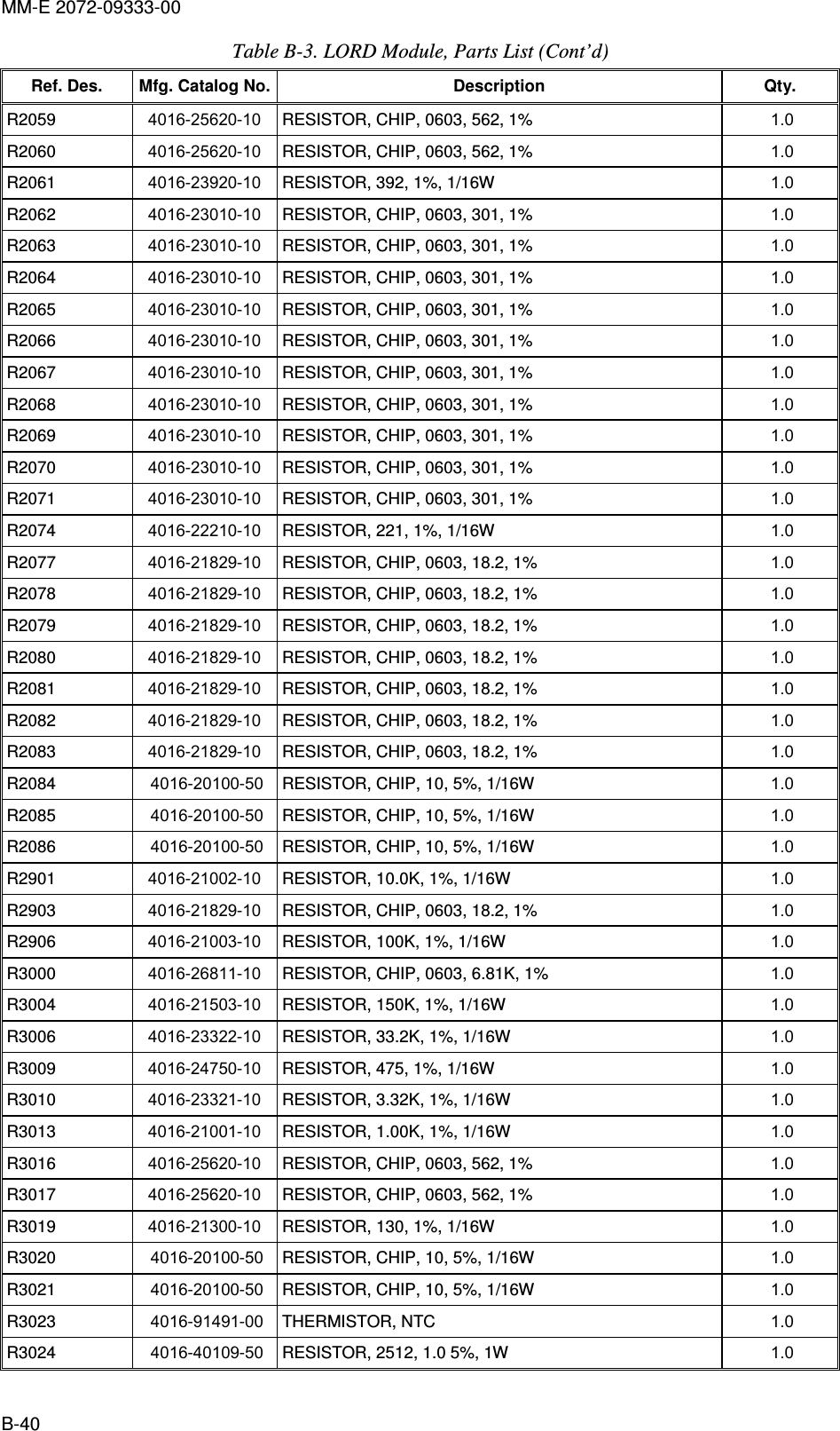
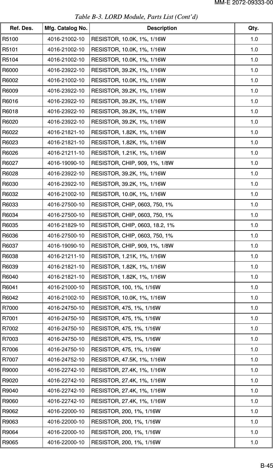
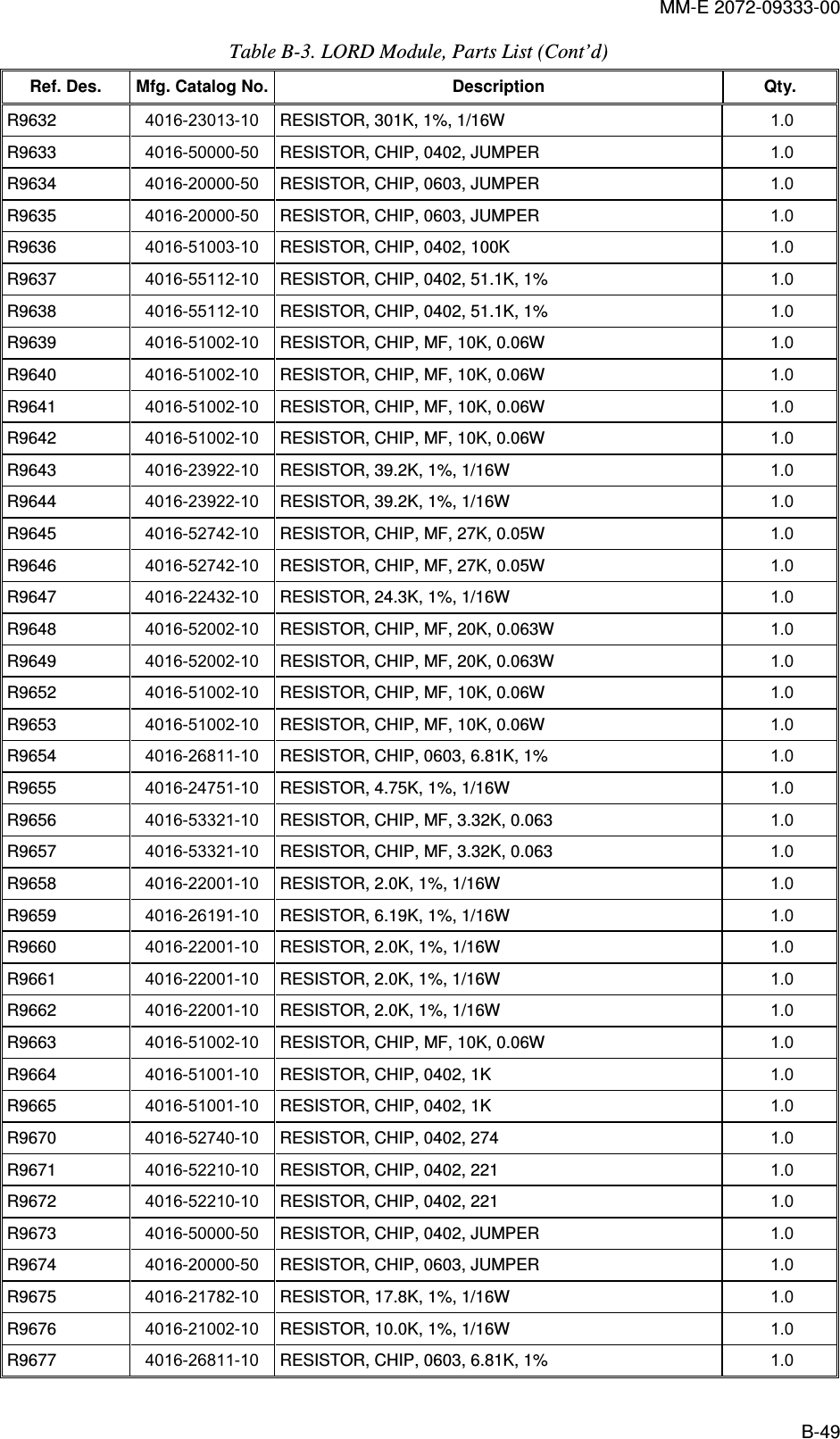
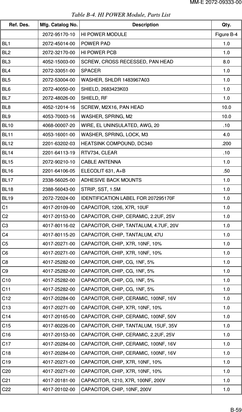
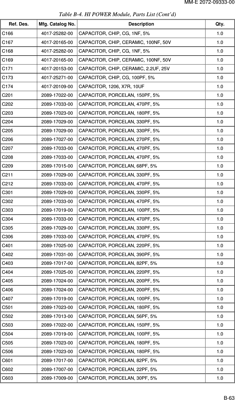
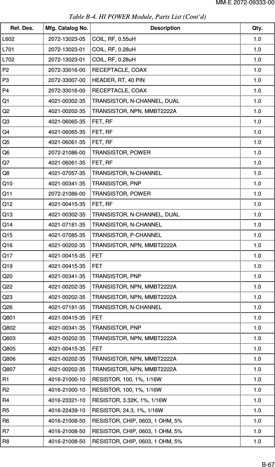
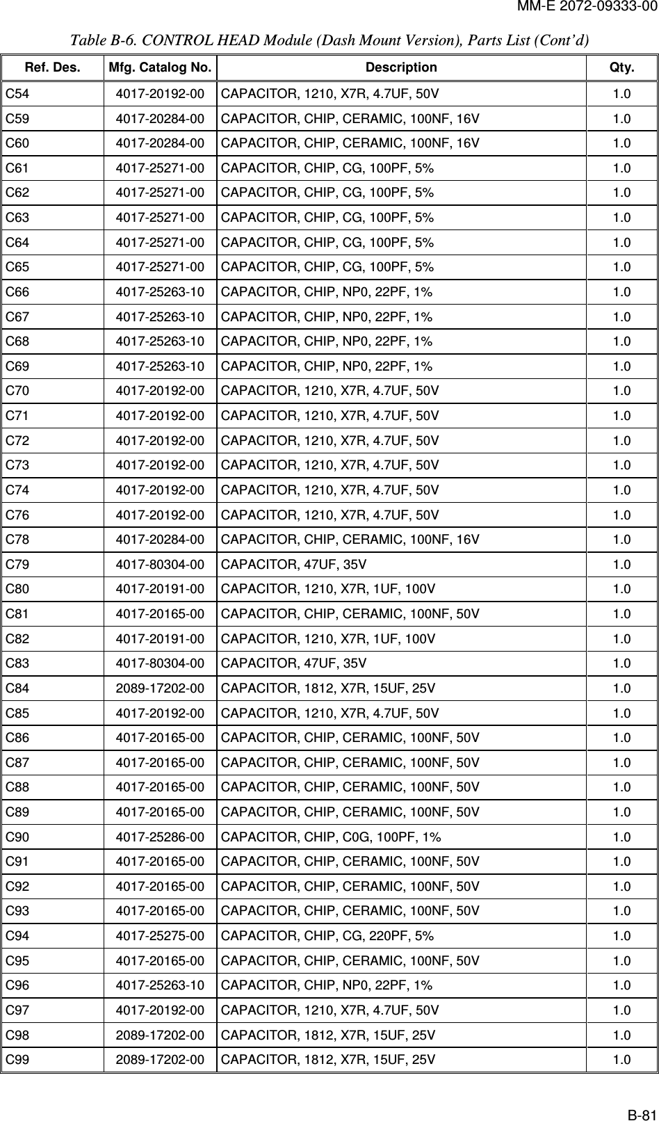
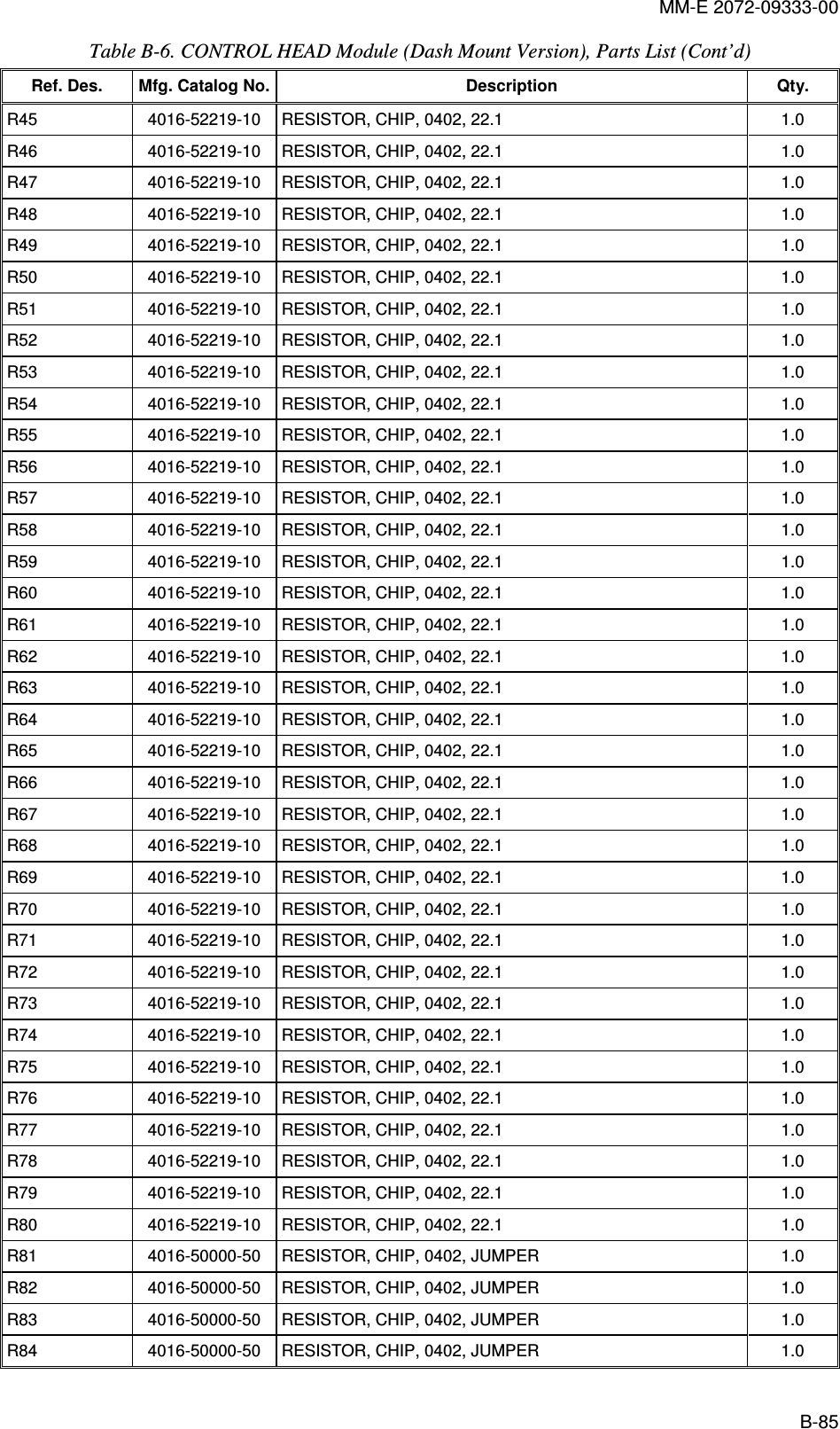
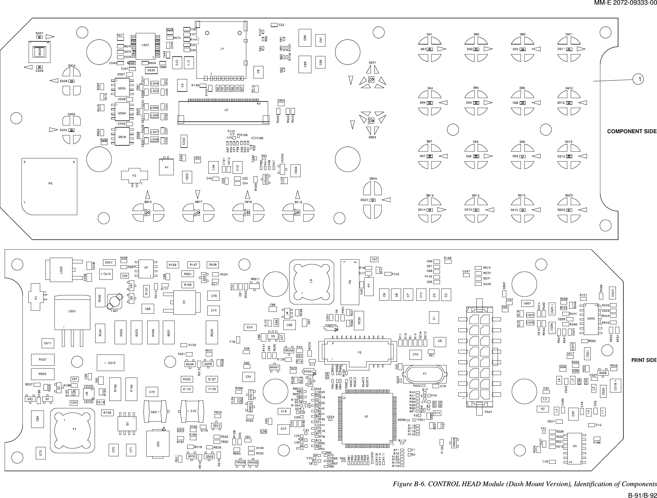
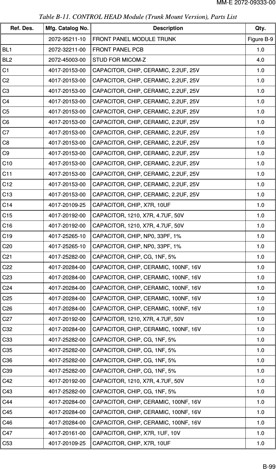
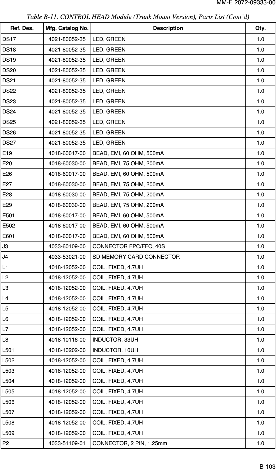
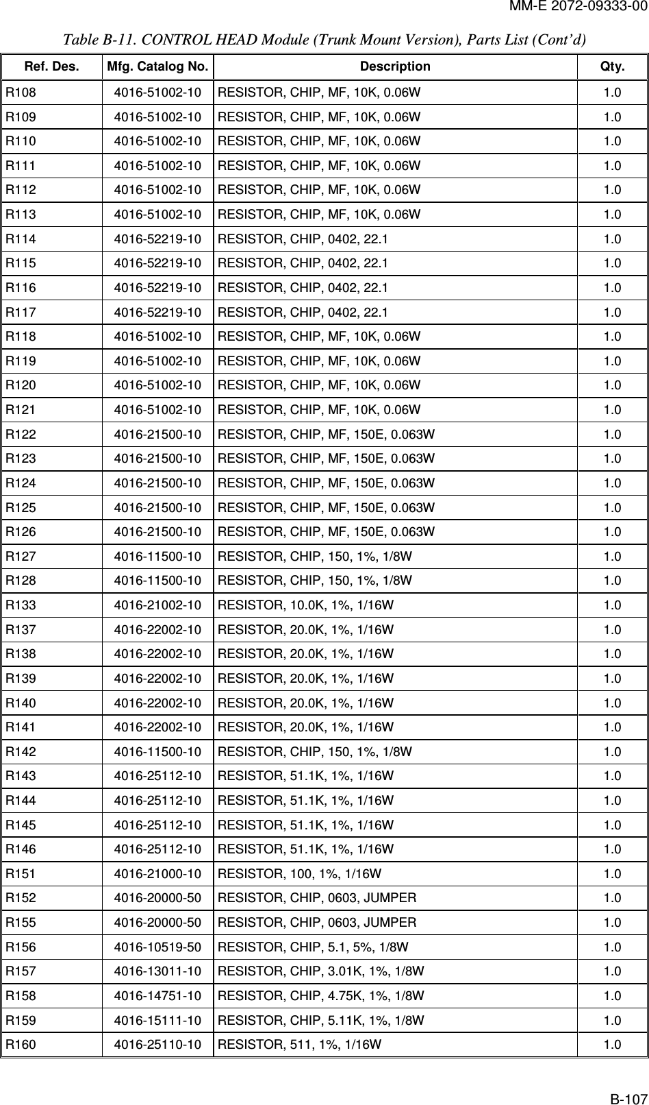
![MM-E 2072-09333-00 SH_DN_232_NON_OFF_SW POW_OFF_CPU3V3A0_CPUCPU_D[7:0]KB_BL_ENKEY_X[4:0]KEY_Y[4:0] LCD_BL_ENLCD_BL_LEVELLCD_HEAT_ENLCD_HEAT_LEVELMISO_CPU MOSI_CPUPTT_MIC_N PTT_MIC_P_CPURD_N_CPURST_N_LCDRX_UART0_TTLRX_UART1_TTLSCL_CPUSDF_SW_DETTX_UART0_TTLTX_UART1_TTLV0_LCDVLED_HEAT_ENWR_N_CPUXCS_N_LCDXCS_N_SDFXIL_MONITORTAD_CODAN_MODEMZ_CPUUART0UART113V8_DC13V8_RADIO_TRUNK3V35V05V0_RADIO8V0_AUDIOKB_BL_ENLCD_BL_ENLCD_BL_LEVELLCD_HEAT_ENLCD_HEAT_LEVELON_OFF_CONTON_OFF_SWPOW_OFF_CPUPTT_MIC_N PTT_MIC_PVDD_LCD_3V0VHEAT_LCDVLED_BL_KBVLED_BL_LCDVLED_HEAT_ENPOW_SUPPLY3V3KEY_X[4:0]KEY_Y[4:0]MISO_CPUMOSI_CPUSCL_CPUSDF_SW_DETVLED_BL_KBXCS_N_SDFMZ_IF8V0_AUDIOMIC_INTX_AUDIO_MTX_AUDIO_PAUDIO_BIOS_BLKSH_DN_232_N3V35V0CH_RXD_MCH_RXD_PCH_TXD_MCH_TXD_PPTP_RXDPTT_MPTT_MIC_PPTT_PRX_UART1_TTLTRUNK_RX_UART0_TTLPTP_TXDTX_UART0_TTLTX_UART1_TTLRS_INTERFACEASSEMBLED FOR TRUNK ONLYDASH ONLYHHHHLL68P80P<=LCDCH_TXD+CH_RXD+TO CHECKNOT ASSEMBLED IN DASH MODE3V6NOT ASSEMBLED IN TRUNK MODEFOR TAD/COD MODES RESOLVINGTABLE 1ASSY DASH 2072-95211-00 PLASSY TRUNK 2072-95211-10 PLTRUNK 2072-95211-10DASH 2072-95211-00MODE P/N PART LIST20729521100 PL20729521110 PLPLACE TO THE SILK SCREENSPEAKERTRUNK ONLYDASH ONLYOPTIONASSEMBLED FOR TRUNK ONLYRS_INTERFACE_BLK16101112131423456789115P50143045-1618AUDIOR5020.00.0R501SPKR1_2_POPTIONSPKR_M1234P153261-0290R50510KSPKR_PRX_AUDIO_P110111213141516171819220212223243456789P3104549-3DASH_CONNECTORLABR5041KLAB1KR503LABINTERFACEPOWER_SUPPLYCPUSH_DN_232_NC34 1NLABTAD_CODAN_MODETAD_CODAN_MODERX_UART1_TTLRX_UART0_TTLPTT_MIC_POSCH_RXD_MCH_RXD_PCH_TXD_PCH_TXD_MPTP_TXDTX_AUDIO_PPTT_MMIC_INMMSZ5227BT1GVR501PTP_RXDPTP_TXD13V8_RADIO_TRUNK13V8_RADIO_TRUNK13V8_RADIO_TRUNKRADIO_RX_UART0_TTLTRUNK_RX_UART0_TTLRADIO_RX_UART0_TTL0.0R582R9 2215V04.75KR2295V0_RADIO5V0_RADIOSPKR_PSPKR_MTX_UART0_TTLPTT_MIC_N8V0_AUDIO3V313V8_DCPTP_RXDR181 0.0TX_AUDIO_PANODE(RED)CATODE(BLACK)12P4SM02B-SRSS1234P253261-0290VHEAT_LCDVLED_BL_LCDON_OFF_SWPOW_OFF_CPUPTT_PTX_AUDIO_MON_OFF_CONT3V3ON_OFF_CONTLCD_HEAT_ENLCD_HEAT_ENVLED_HEAT_ENLCD_HEAT_LEVELVLED_HEAT_EN5V0KB_BL_ENKEY_X[4:0]KEY_Y[4:0]8V0_AUDIOC506100NMIC_INPTT_MIC_P_CPUTX_UART0_TTL10R13VDD_LCD_3V010KR310KR4LCD_HEAT_LEVELLCD_BL_ENLCD_BL_LEVELON_OFF_CONTVDD_LCD_3V0VLED_BL_LCDVLED_BL_KBVHEAT_LCDPTT_MIC_PPTT_MIC_N3V3MISO_CPUR11 OPTIONC21 1NPTT_MIC_PTX_AUDIO_M0.0R180LABR16 4.75KR14 10C7P9876543938373635343332313032928272625242322212021918171615141312111040142J3FH28-40S-0.5SH(05) V0_LCDVLCD_INOUTPTT_MIC_P_CPUXCS_N_SDFCPU_D[7:0]XCS_N_SDFMOSI_CPUSCL_CPUVLED_BL_KBSDF_SW_DETKEY_X[4:0]KEY_Y[4:0]WR_N_CPURST_N_LCDXCS_N_LCDRD_N_CPUA0_CPUXIL_MONITOR1MR12R215 0.010KR5R8 OPTIONOPTIONR7R6 OPTION2.2UC12.2UC10R213 0.00.0R2142.2UC8C7 2.2UR1 0.0R10 OPTIONC13 2.2UC6 2.2U2.2UC12C9 2.2UC11 2.2U2.2UC5C4 2.2U2.2UC22.2UC3SCL_CPUMOSI_CPUVDD_LCD_3V0C6PC2NC1PC3PC1NXCS_N_LCDSCL_CPUMOSI_CPURST_N_LCDRD_N_CPUWR_N_CPUA0_CPUVDD_LCD_3V0SDF_SW_DETC5PV0_LCDC2PC4PV4MISO_CPUV3V2V1IF3IF2IF1CPU_D7CPU_D6CPU_D5CPU_D4CPU_D3CPU_D2CPU_D1CPU_D0TX_UART1_TTL1NC5015V0KB_BL_ENLCD_BL_ENLCD_BL_LEVELRXD =FROM PCTXD = TO PCRX_AUDIO_PTXDRXDC424.7U50VPTT_MIC12345678P643090-0003180PC504C503180P180PC502PTP_RXDL74.7U13V8_DCPTT_MIC_NR154.75K3V3L34.7UL64.7UC361N1NC39MIC_AUDIOMIC_INL44.7U4.7UL1L24.7UC351NC44100NR2 104.7UL5 1NC33AUDIO_OUTXIL_MONITOR1NC43PTP_TXDC505180PPOW_OFF_CPUON_OFF_SWRX_UART0_TTLR60110K3V3SH_DN_232_NTX_UART1_TTLRX_UART1_TTLPTP_TXDPTP_RXD3V3CH_TXD_PCH_TXD_MPTT_MIC_PTX_UART0_TTLTRUNK_RX_UART0_TTLPTT_PPTT_MCH_RXD_PCH_RXD_M5V0 Figure A-3.A. CONTROL HEAD Module, Schematic Circuit Diagram (Sheet 1 of 6 – Module Interconnection Diagram) A-51/A-52](https://usermanual.wiki/Elbit-Systems-Land-and-C4I-Tadiran/MICOM-TRK125W.Service-Manual/User-Guide-2016167-Page-102.png)
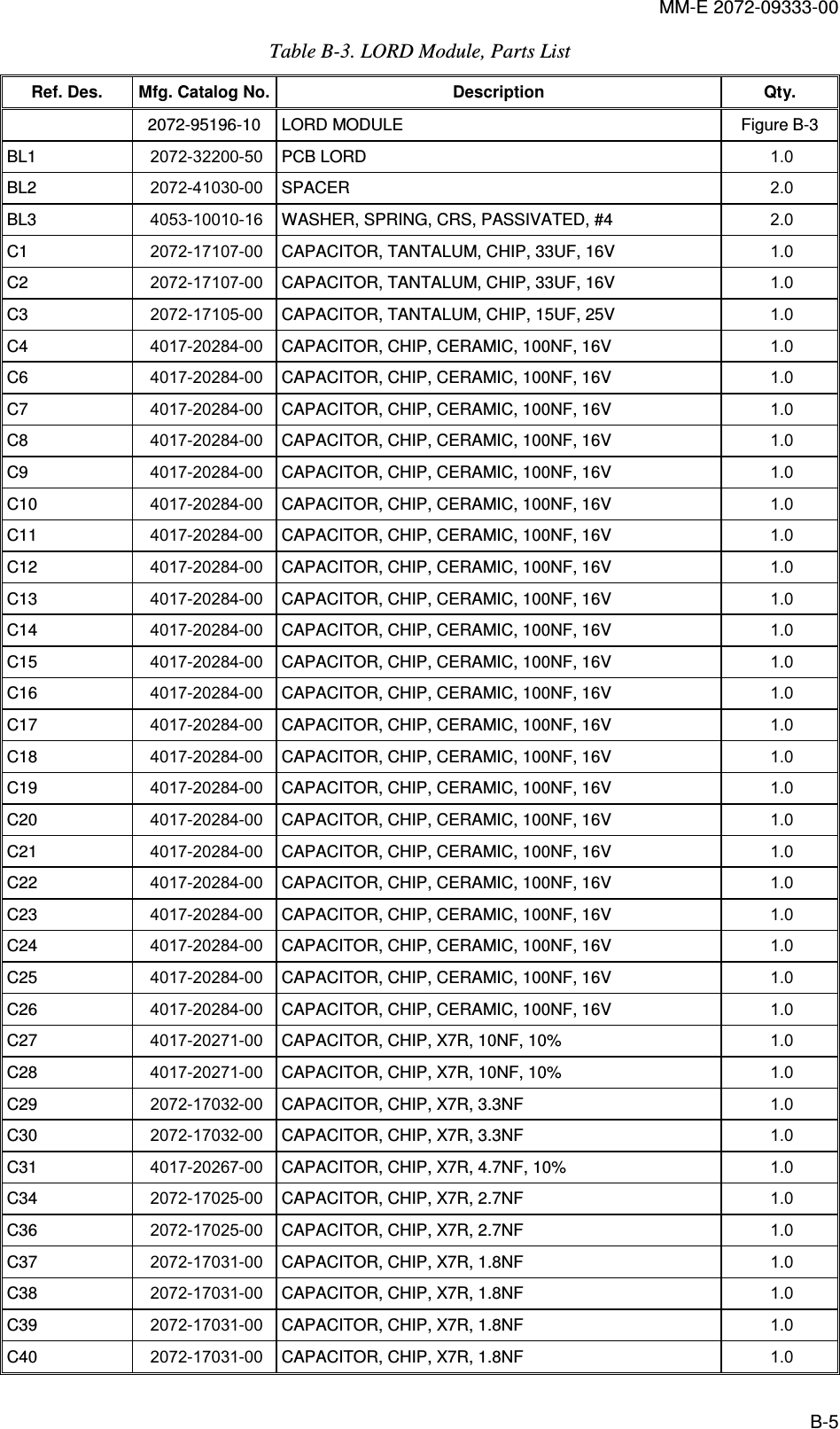
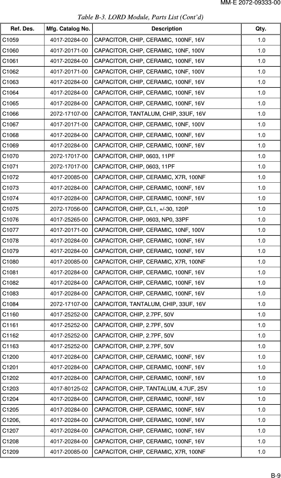
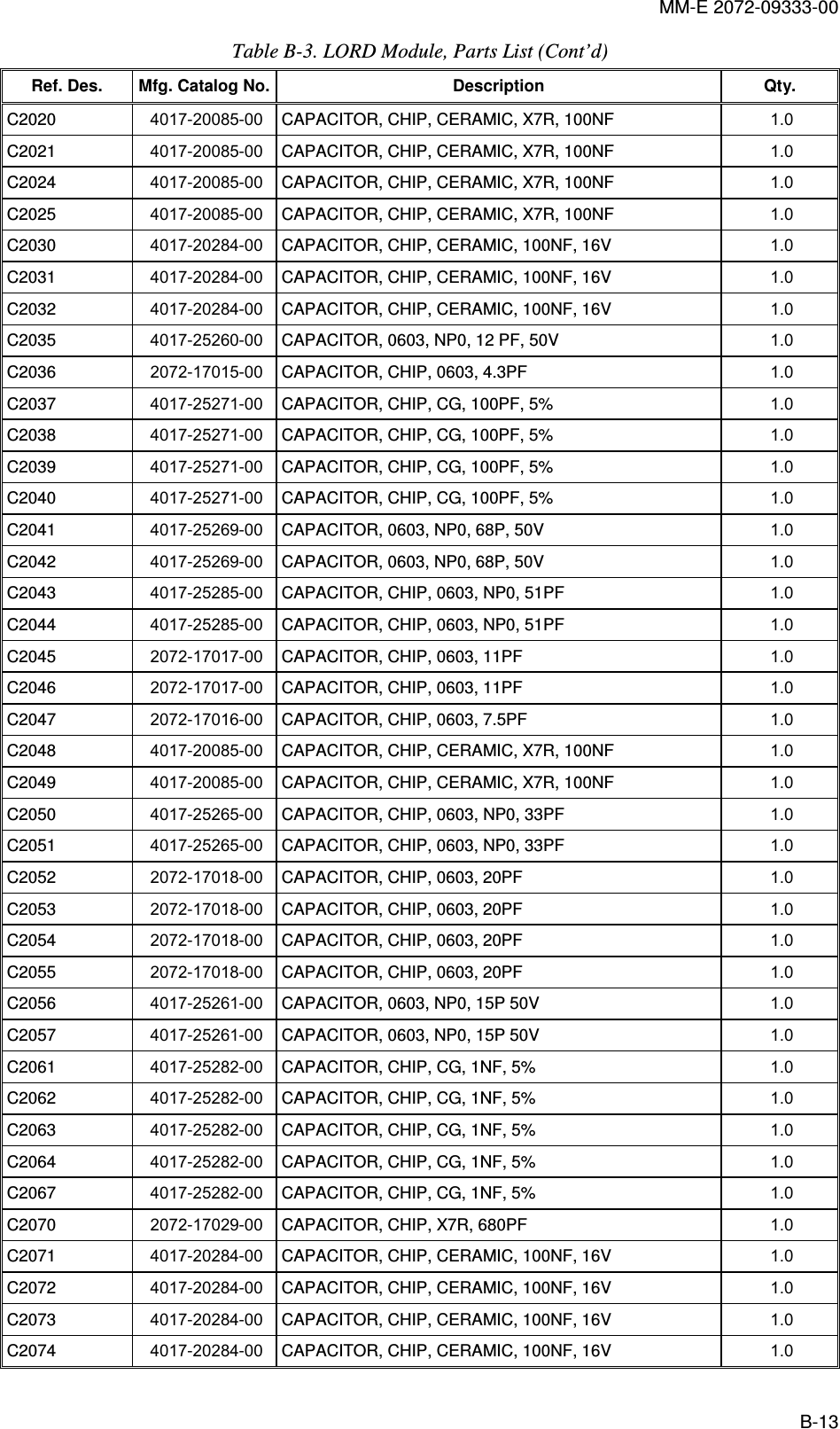
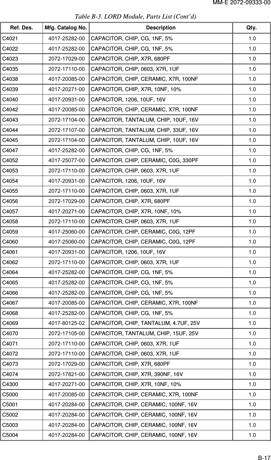
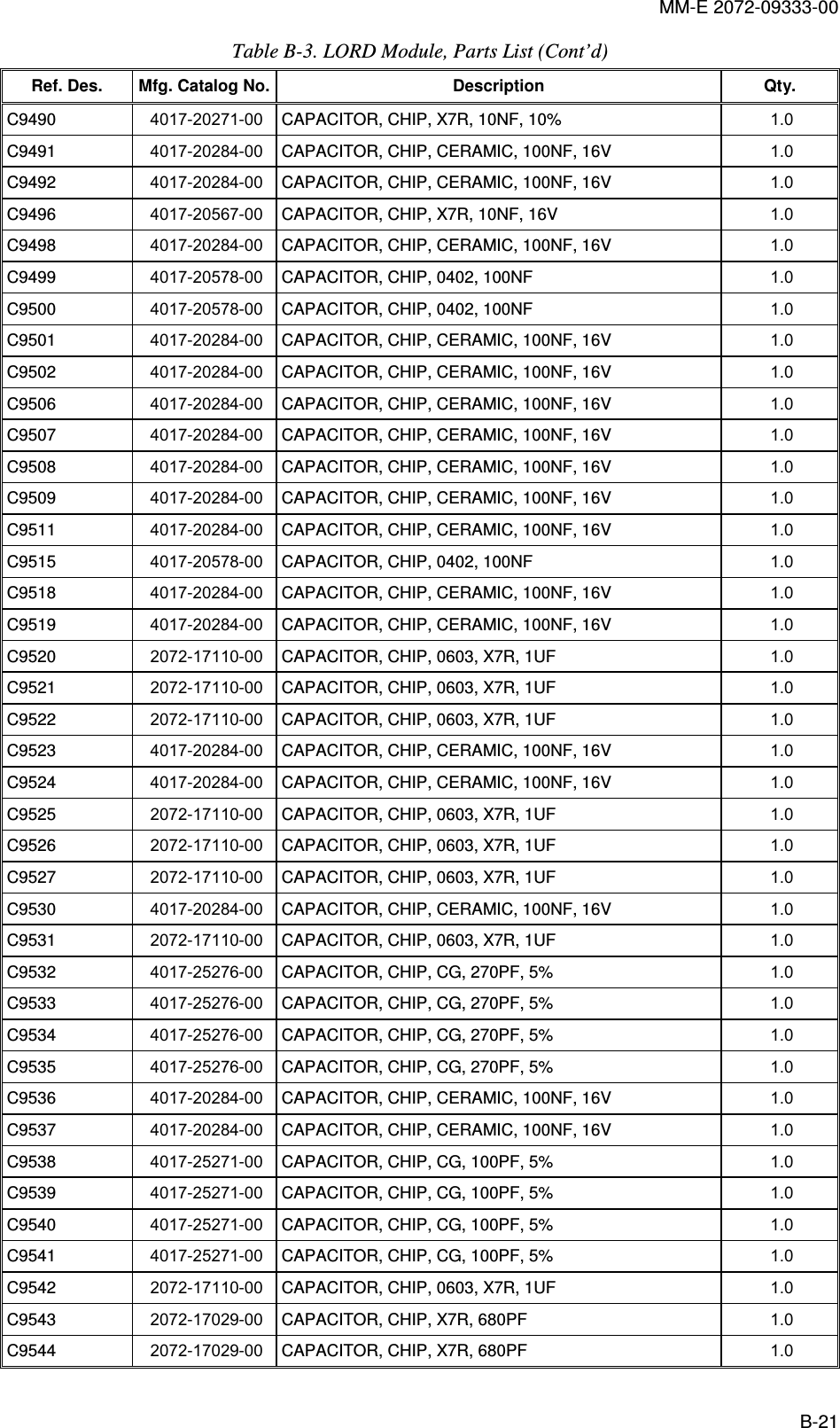
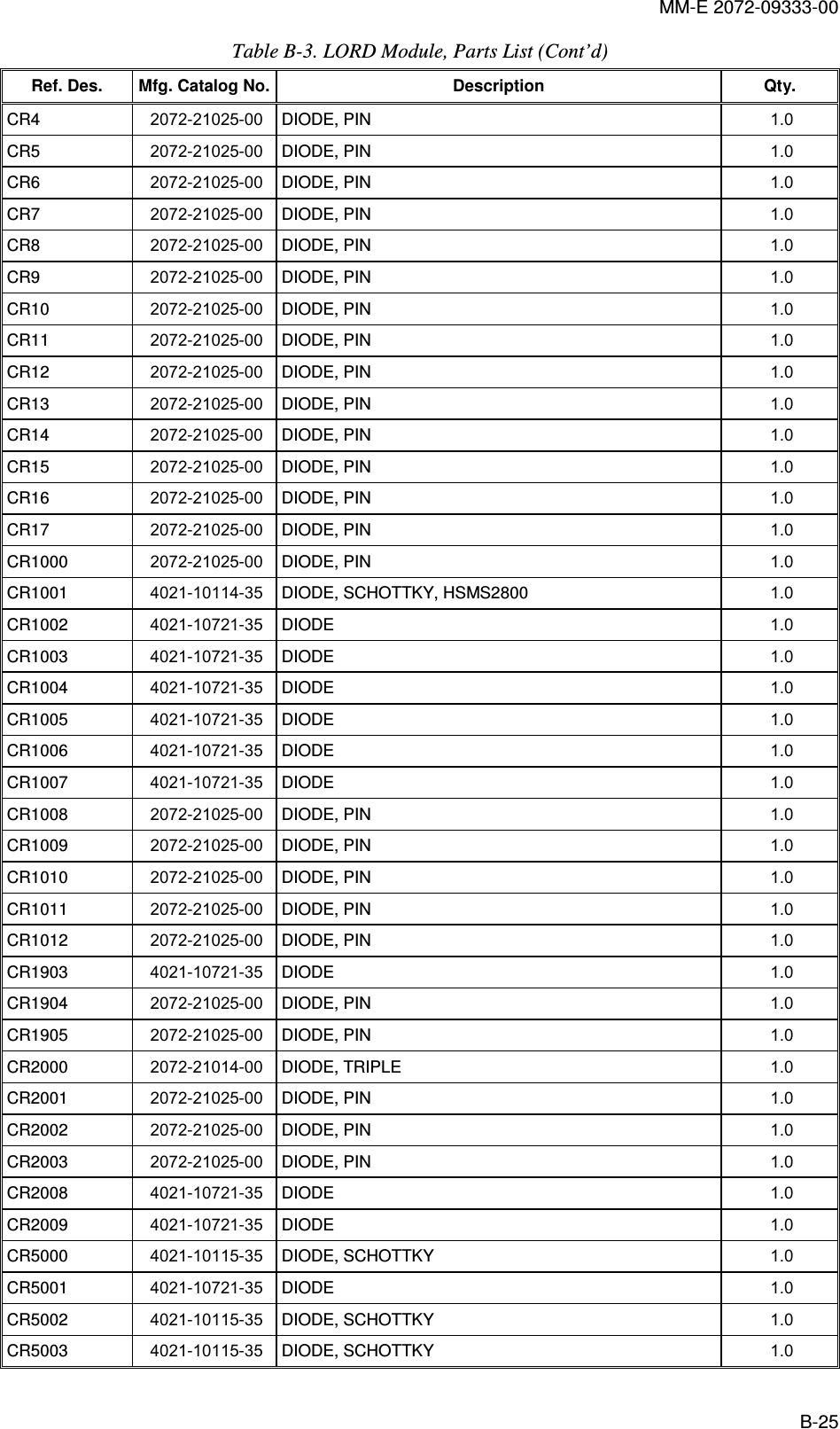
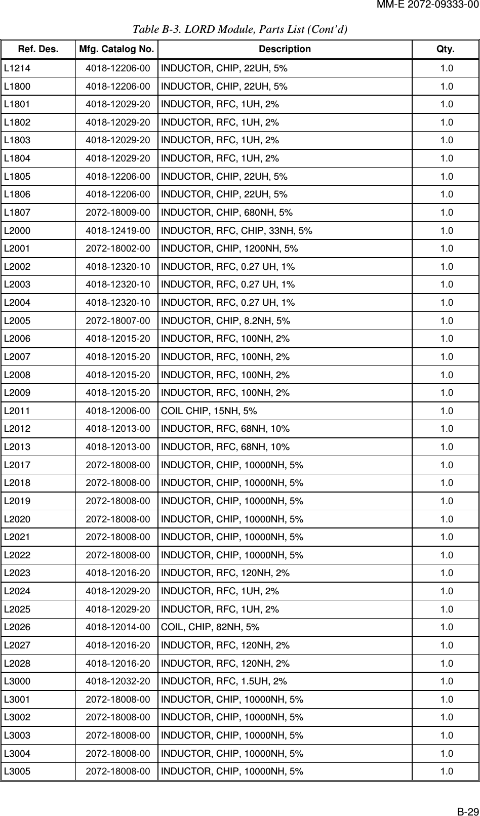
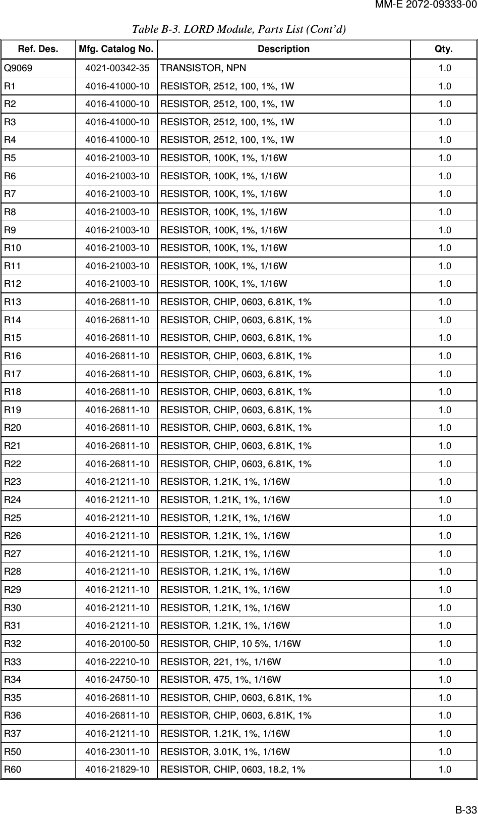
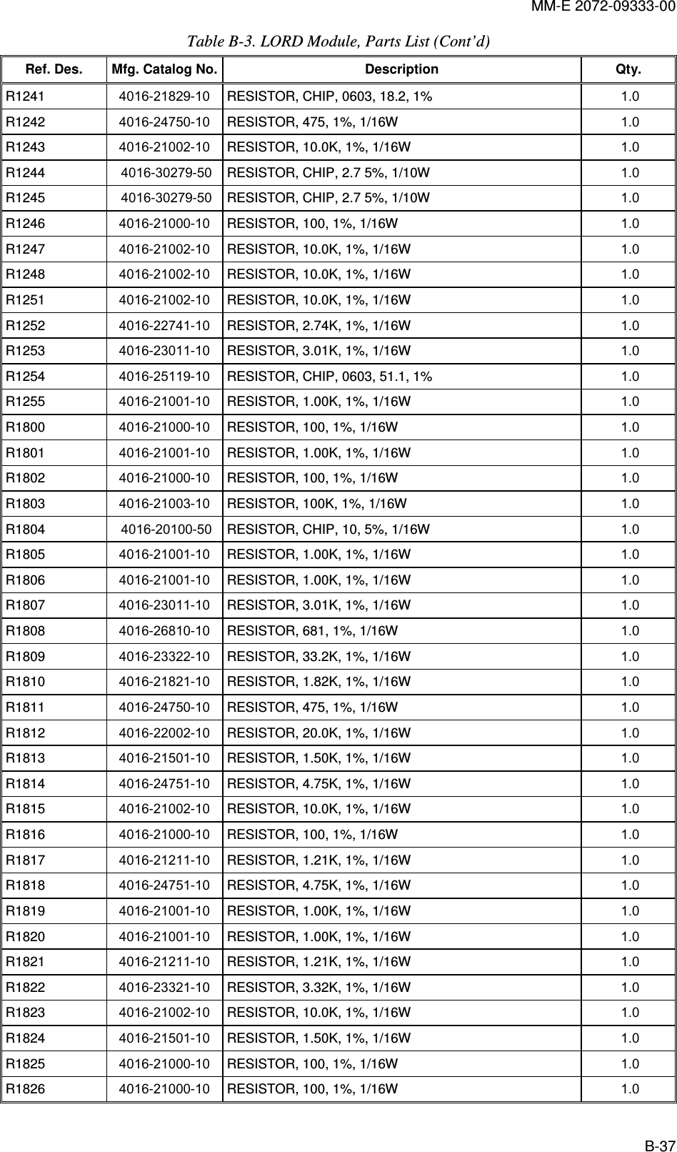
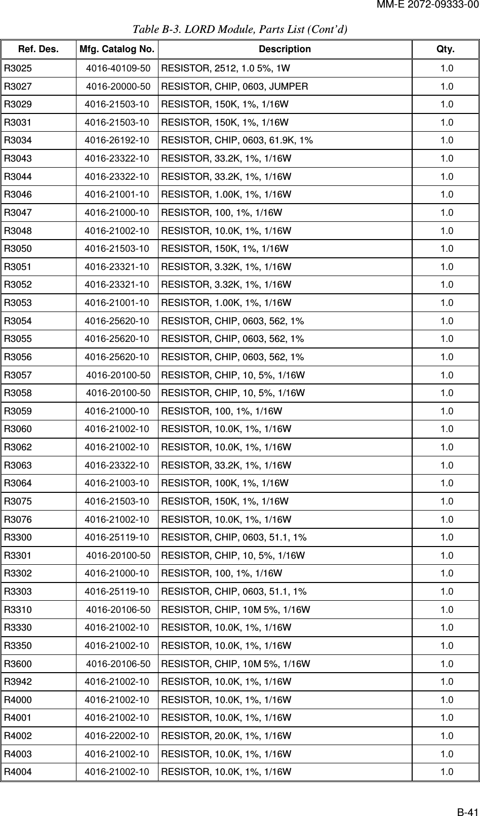
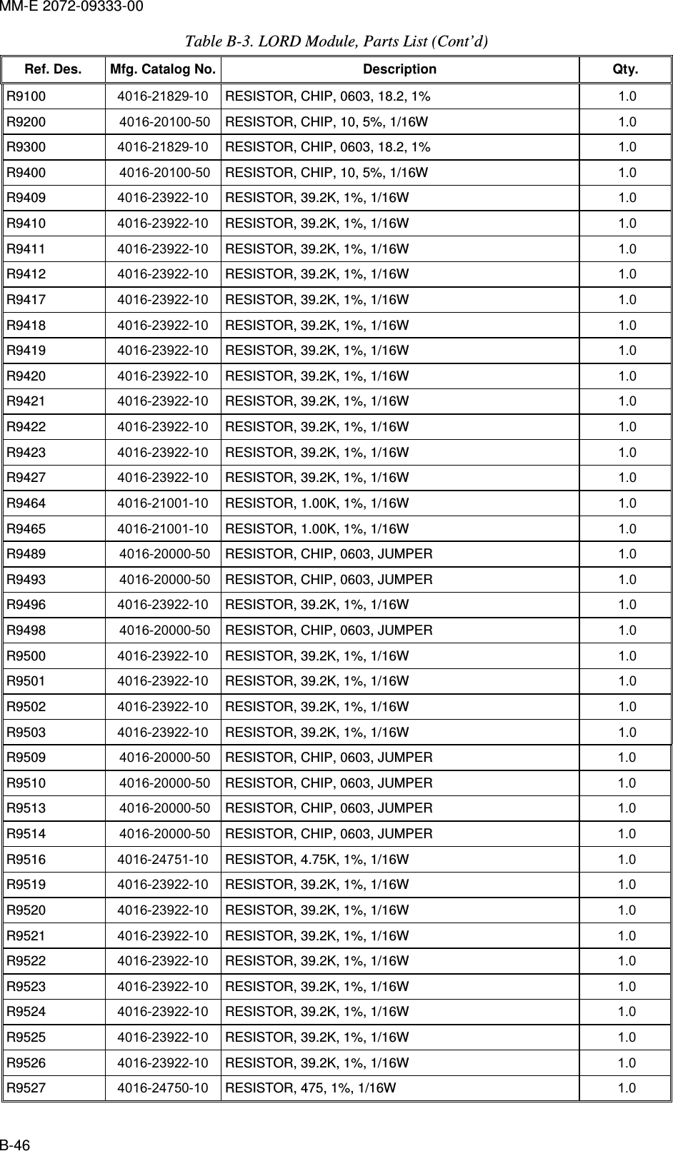
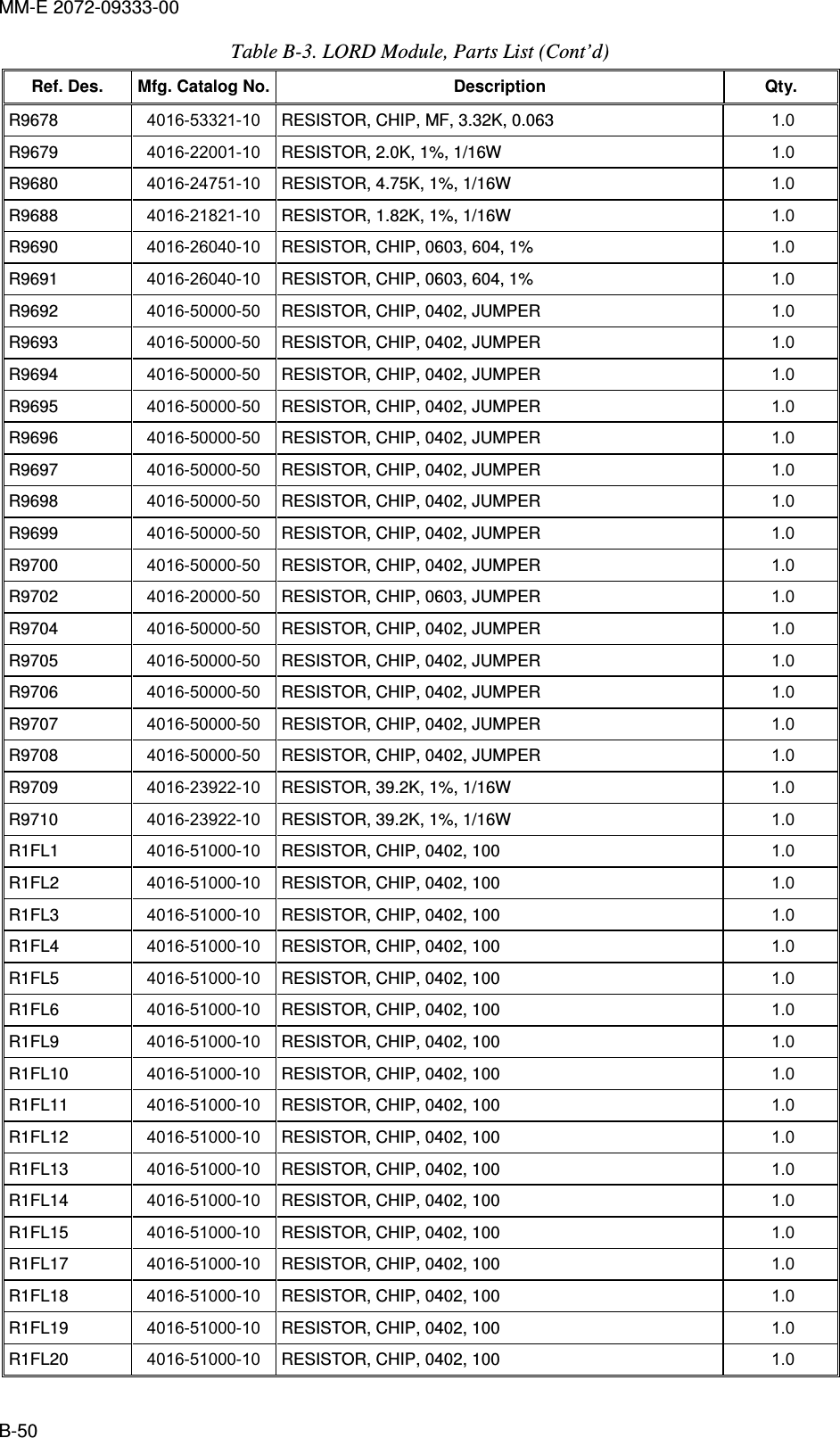
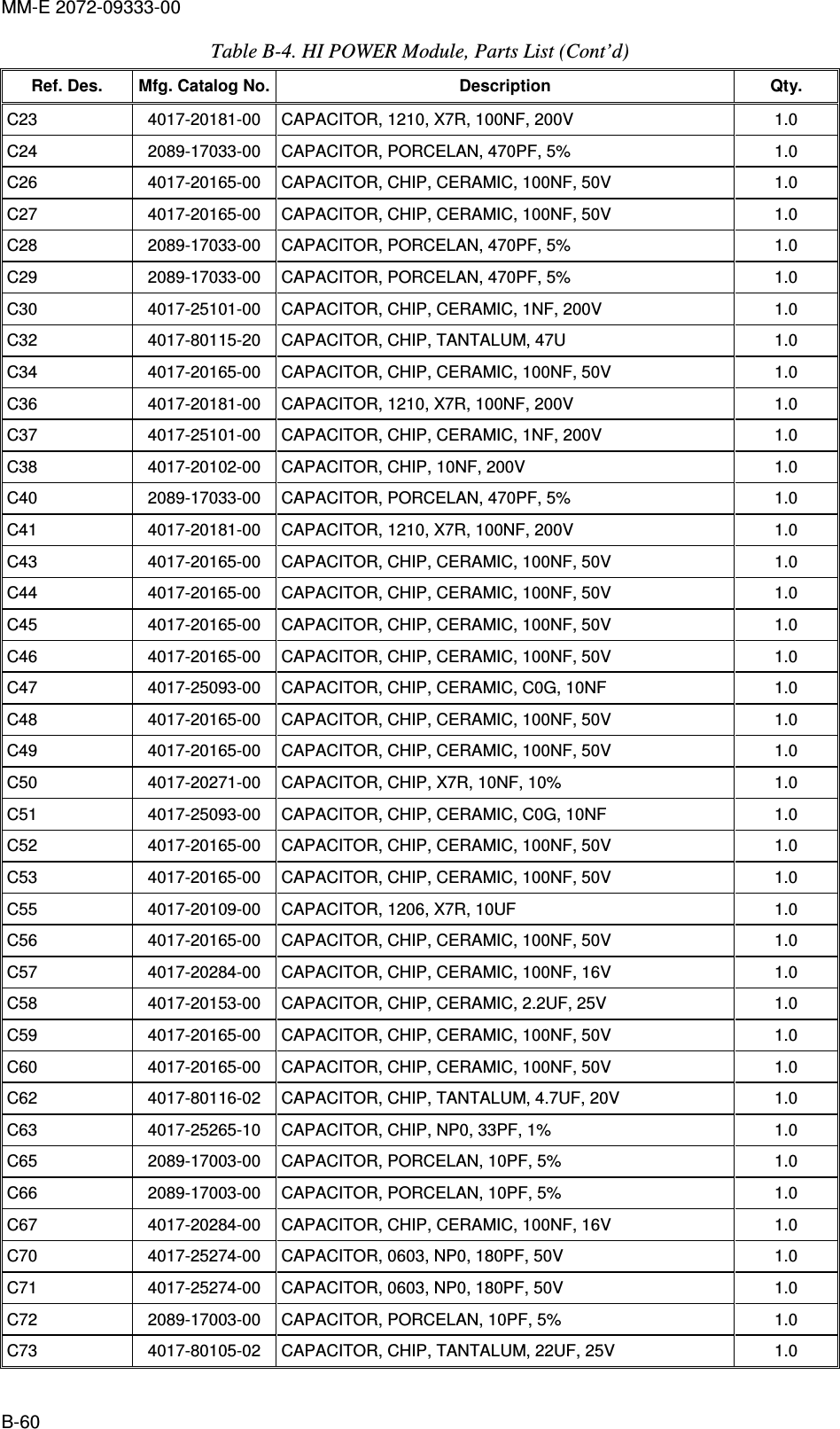
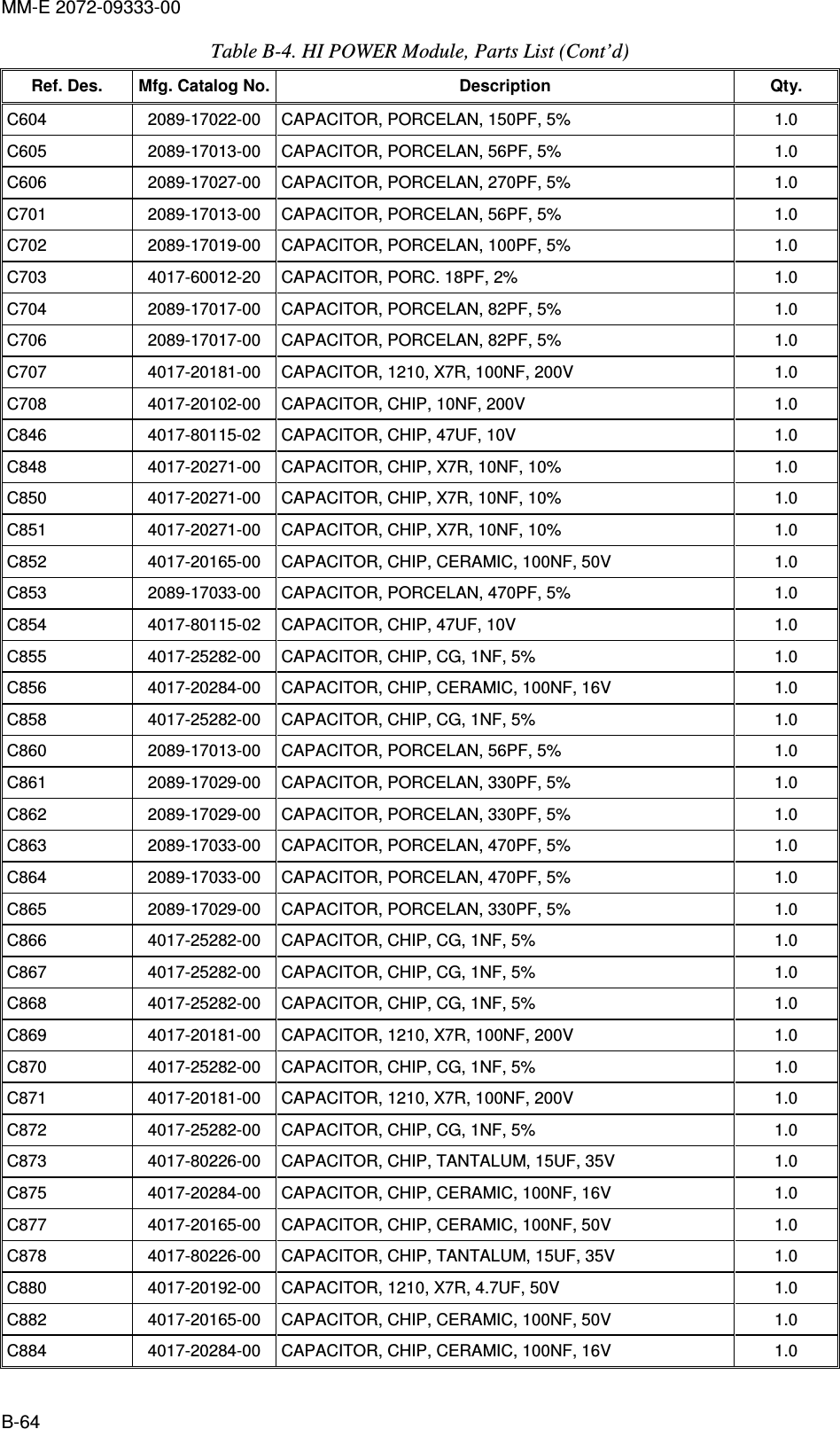
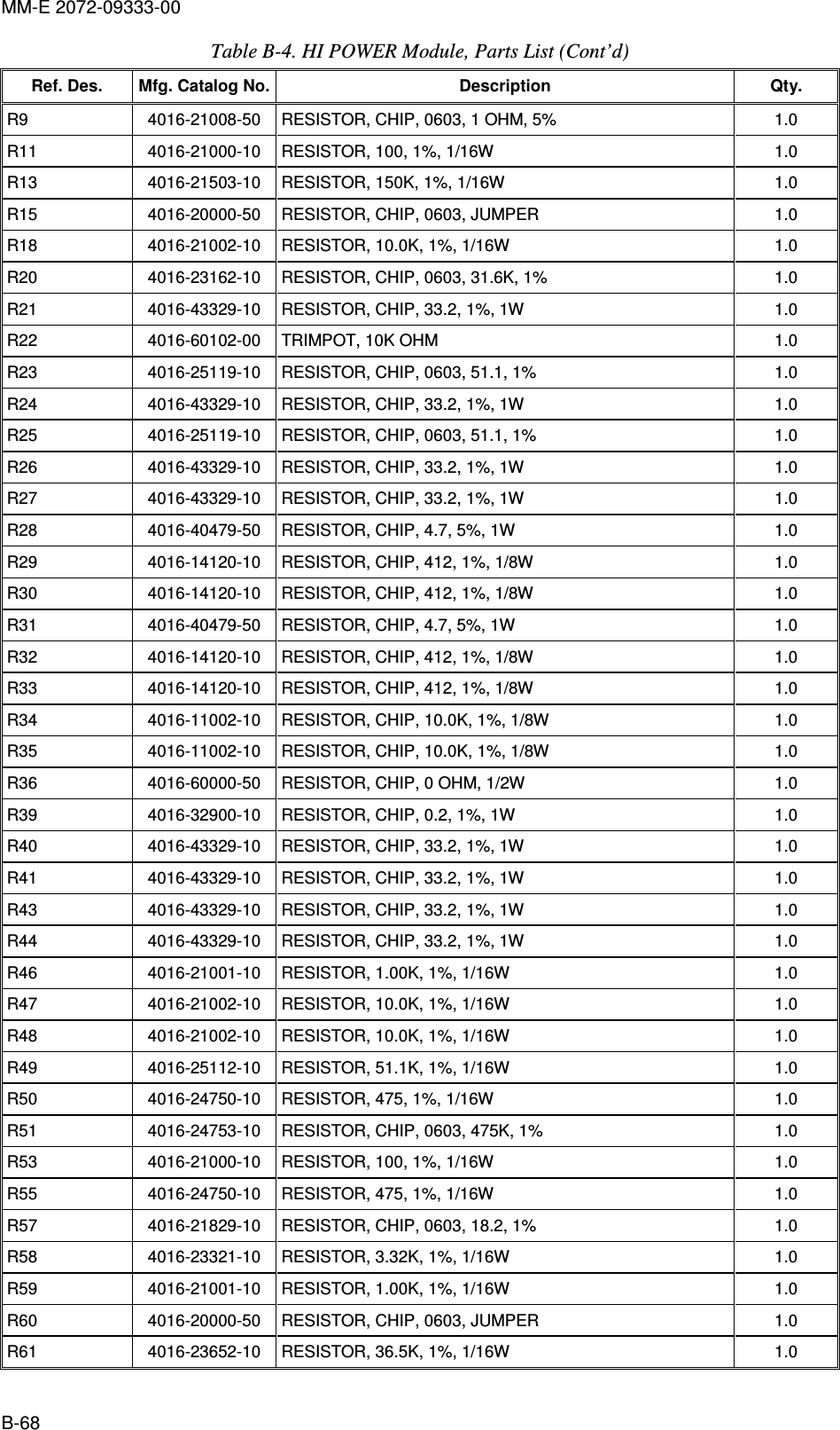
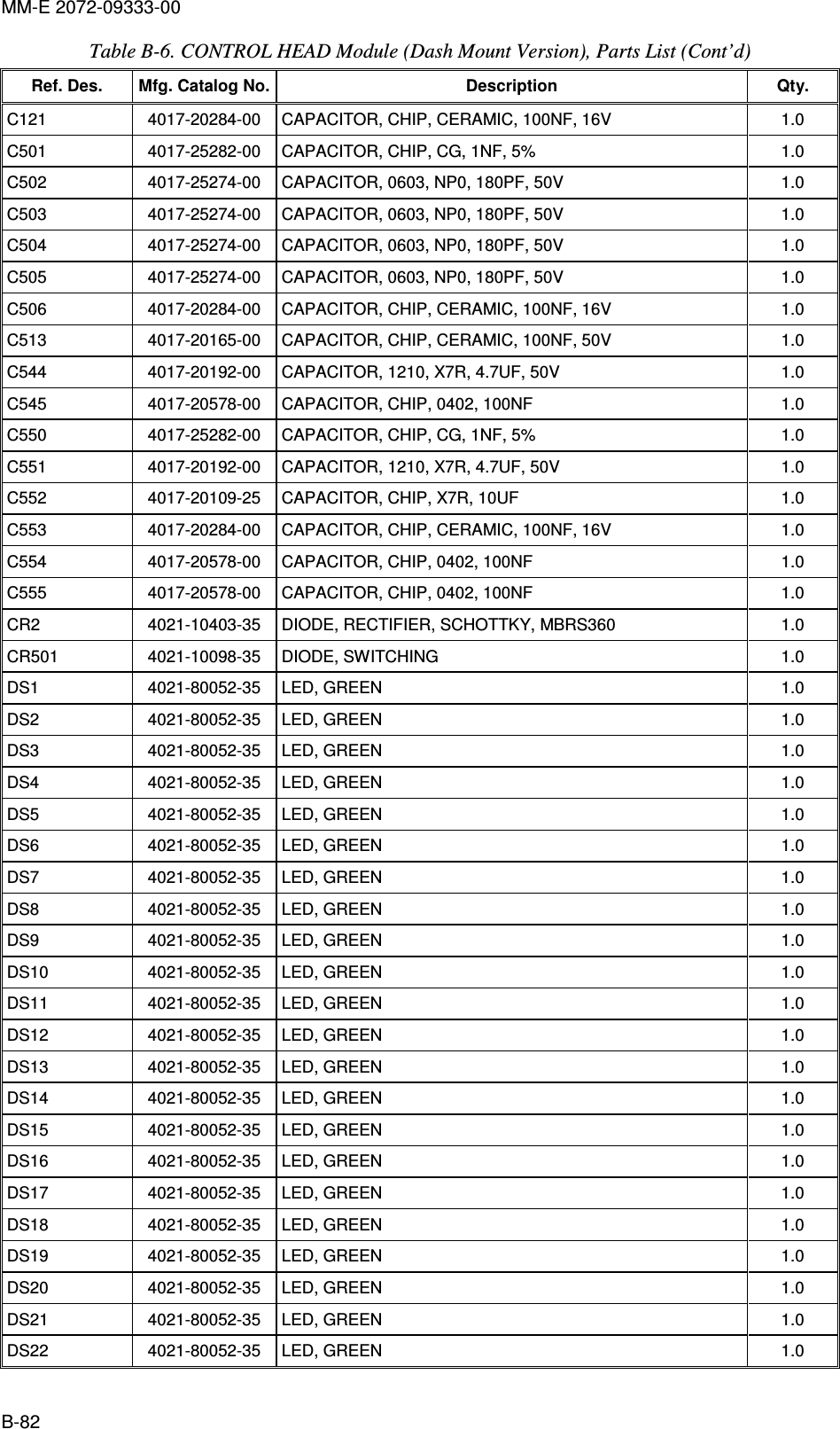
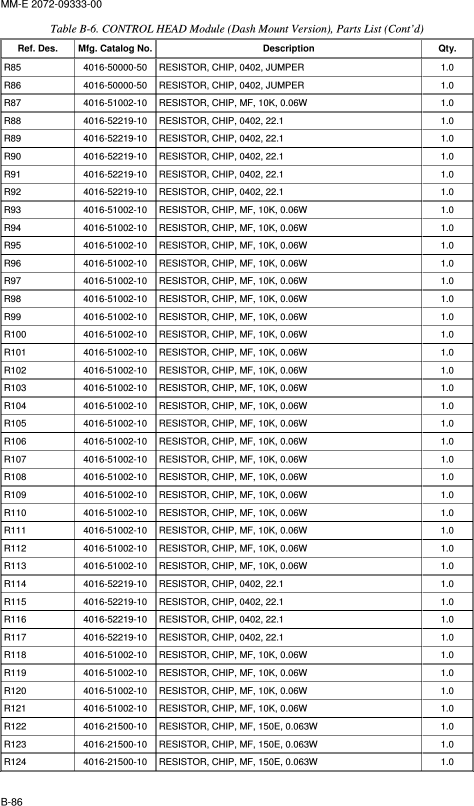
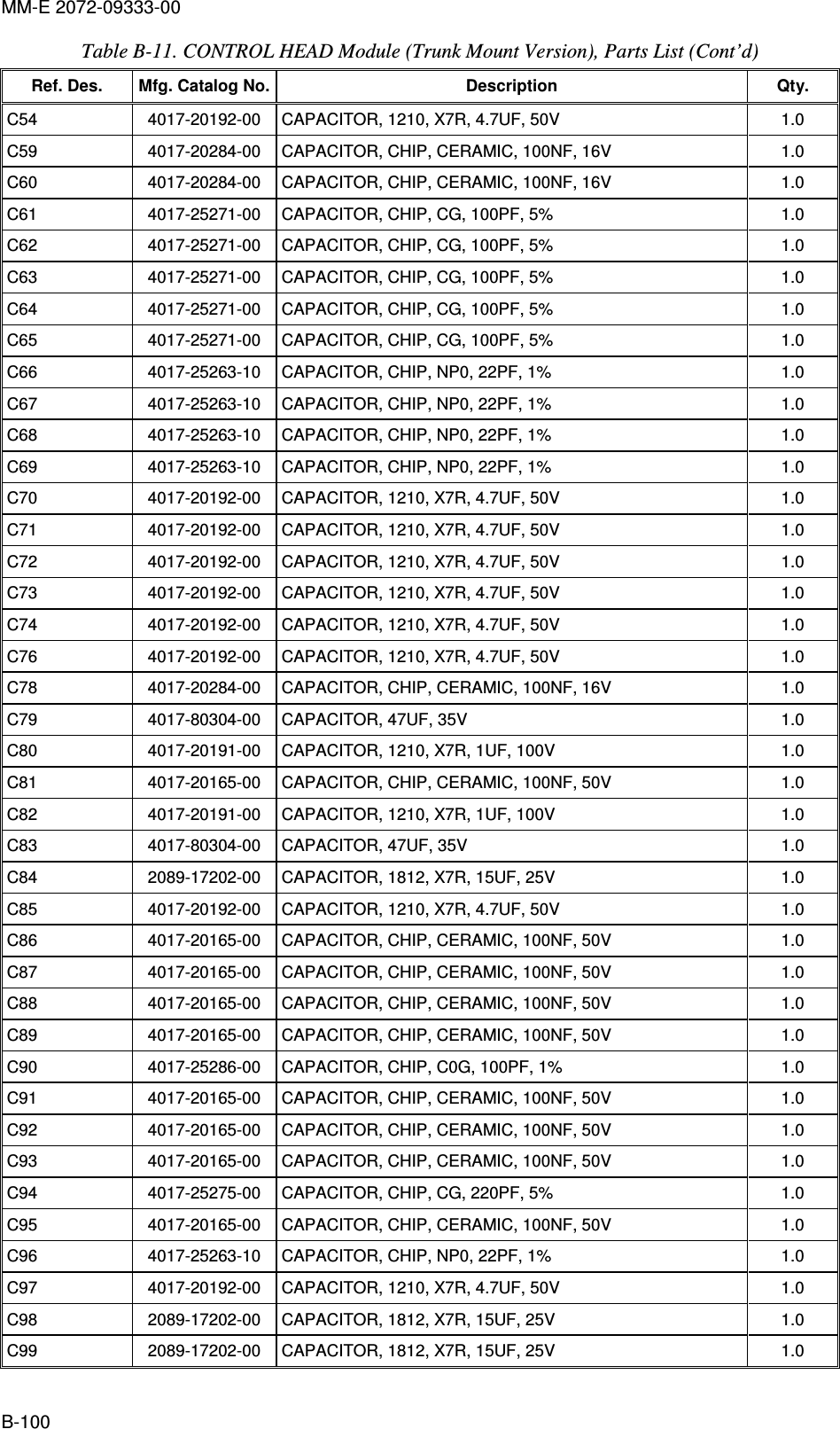
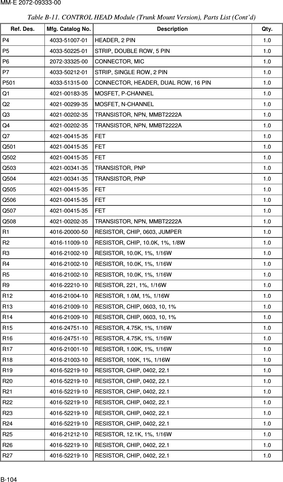
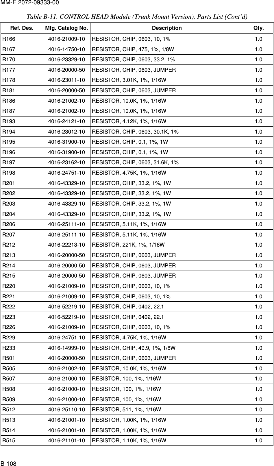
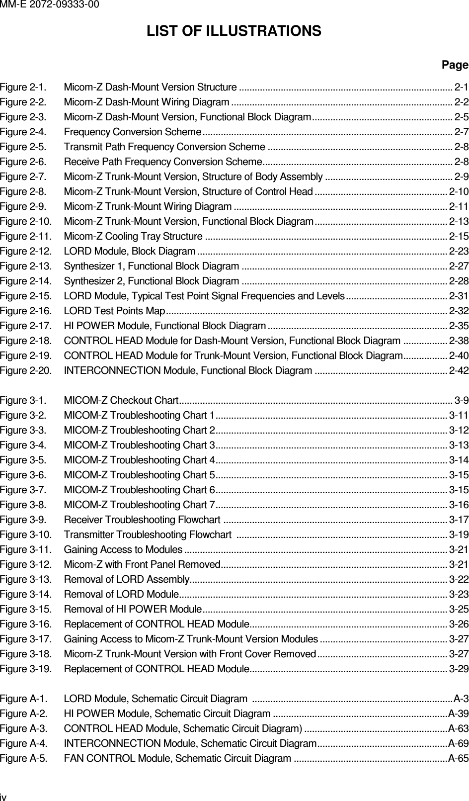
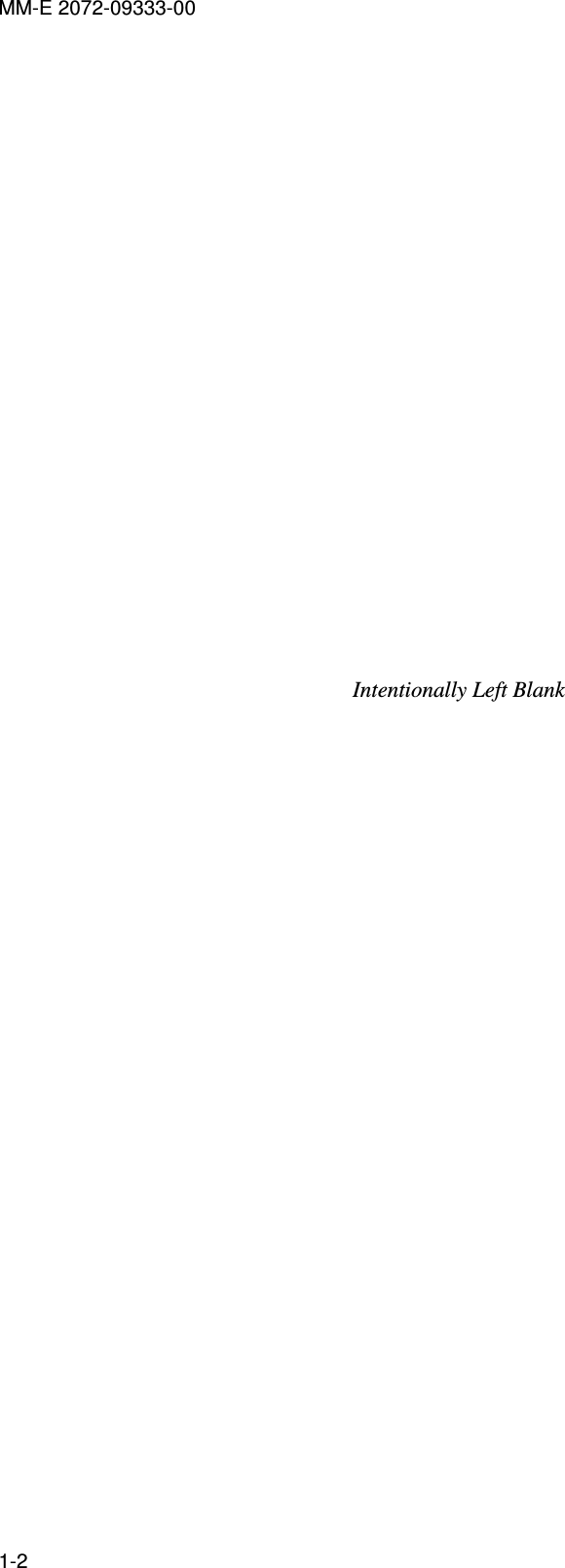
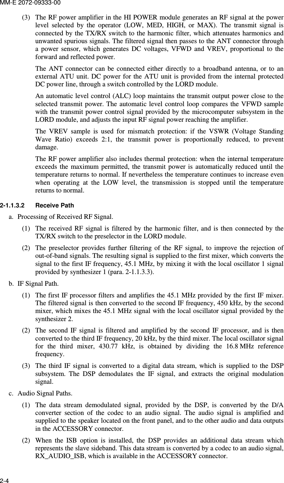
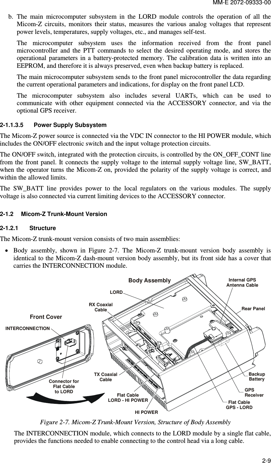
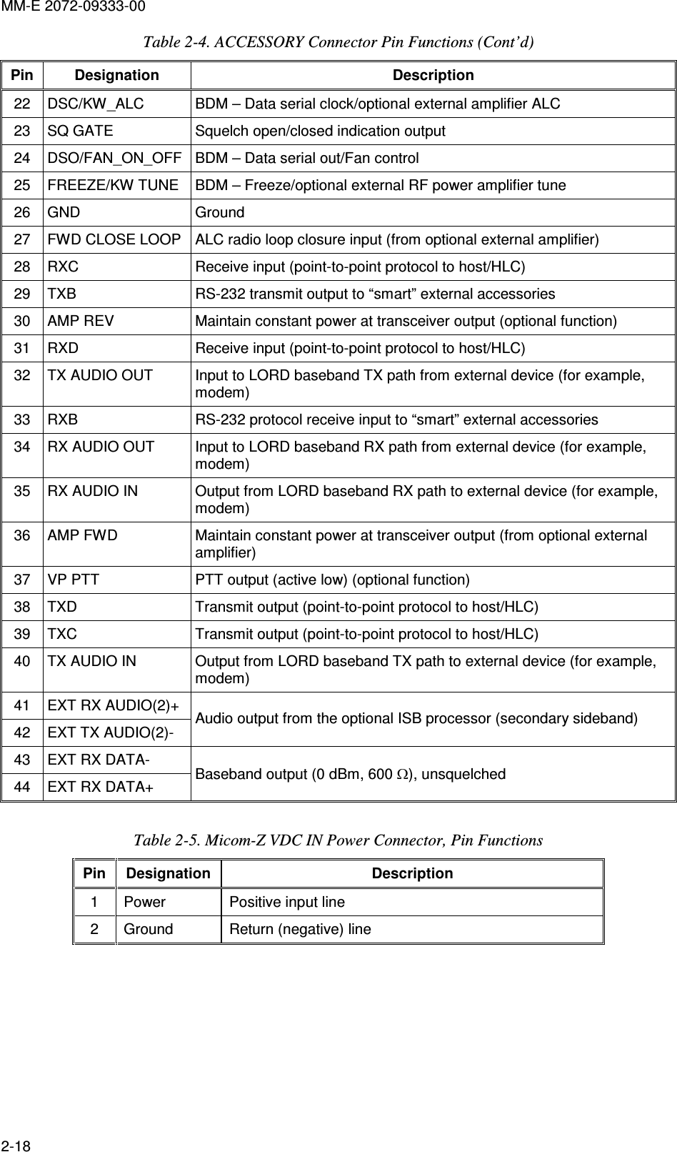
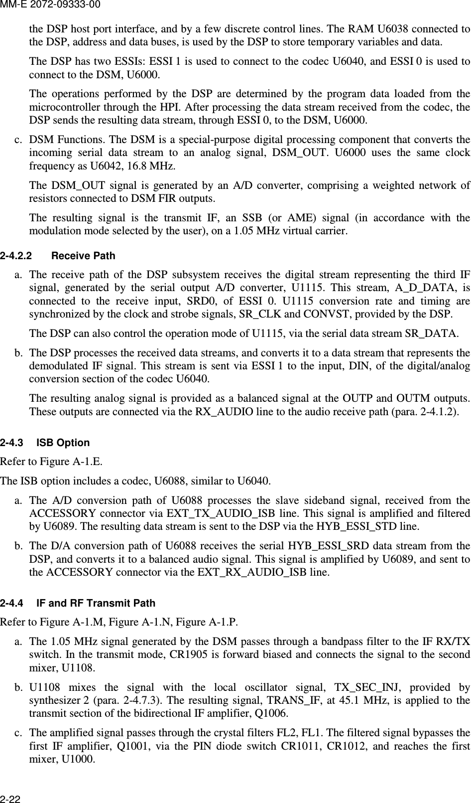
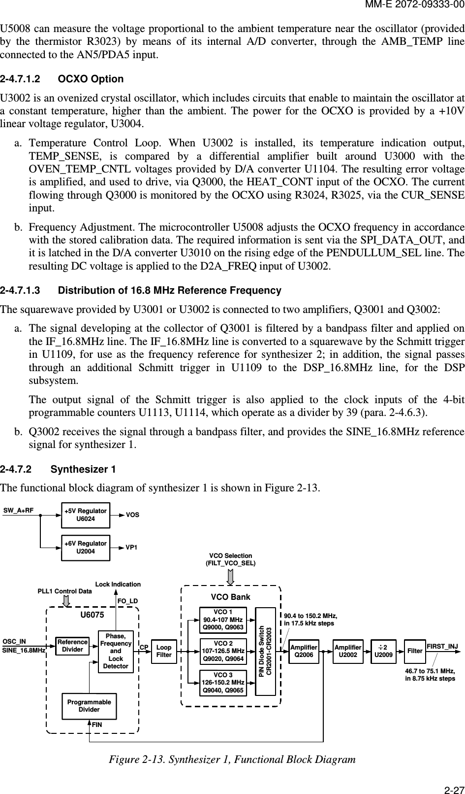
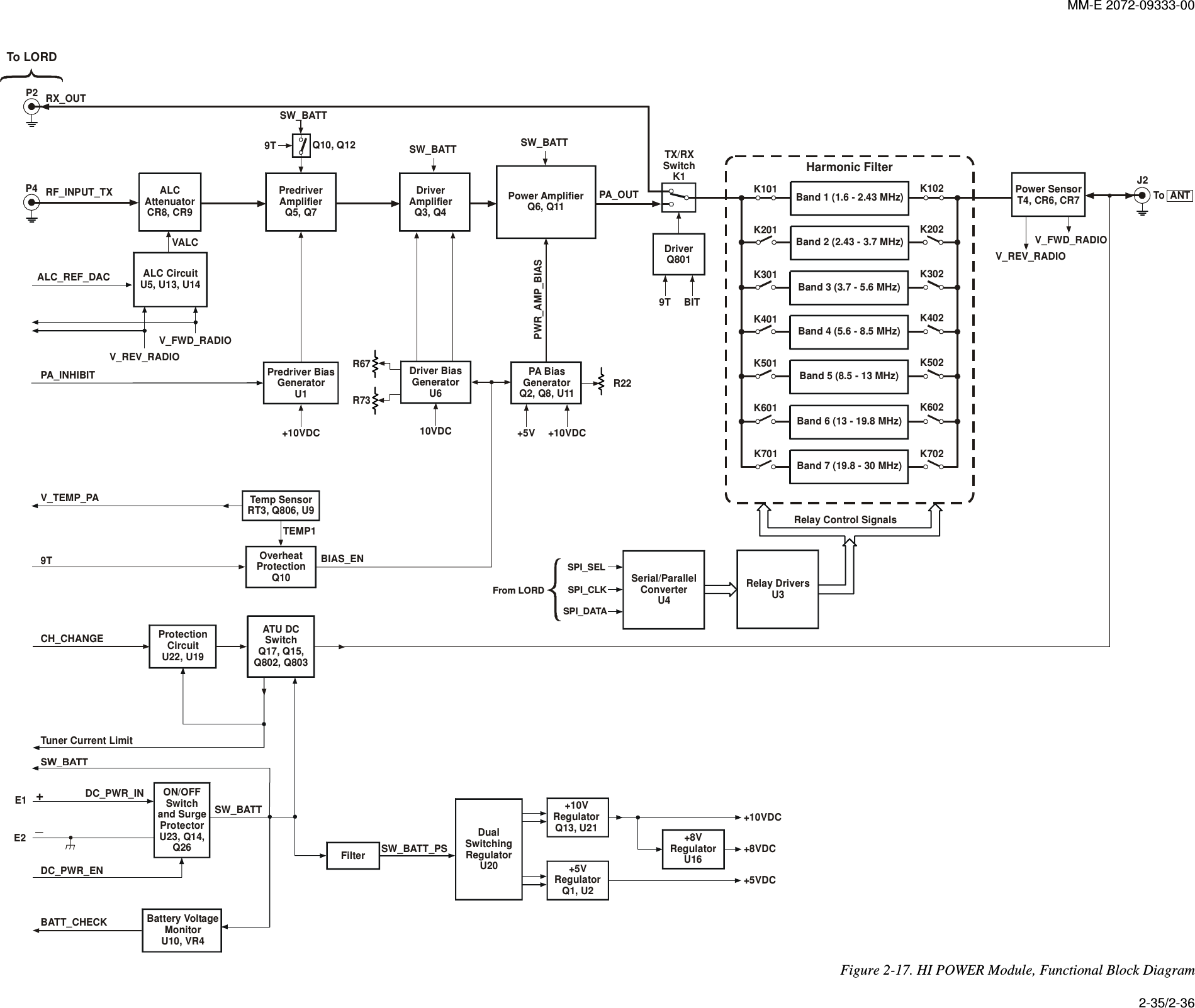
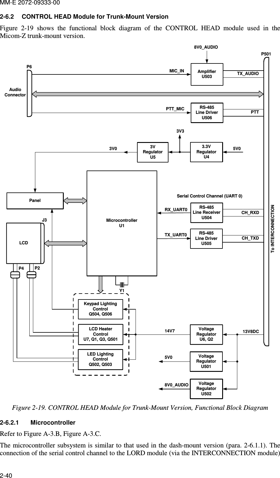
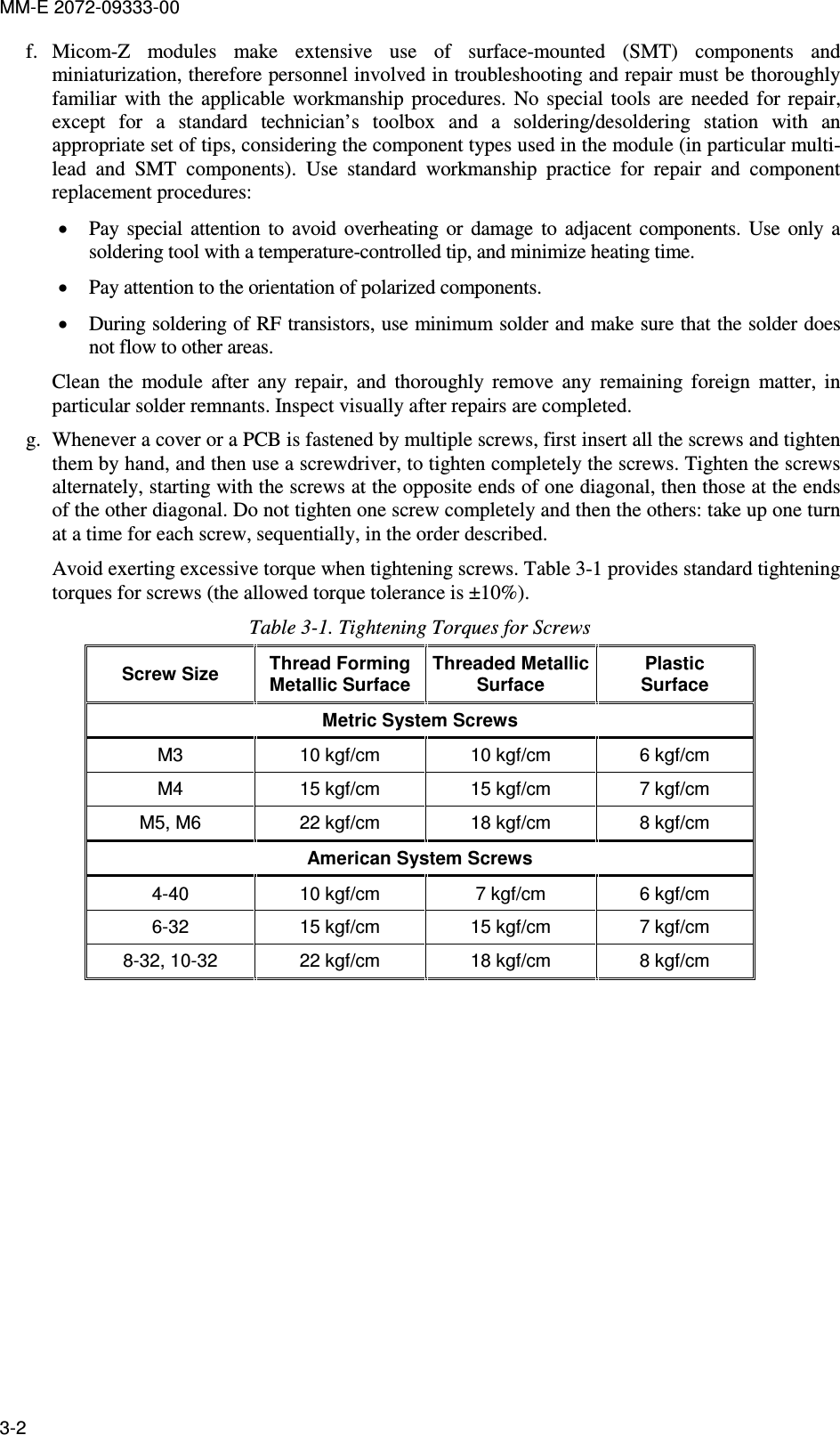
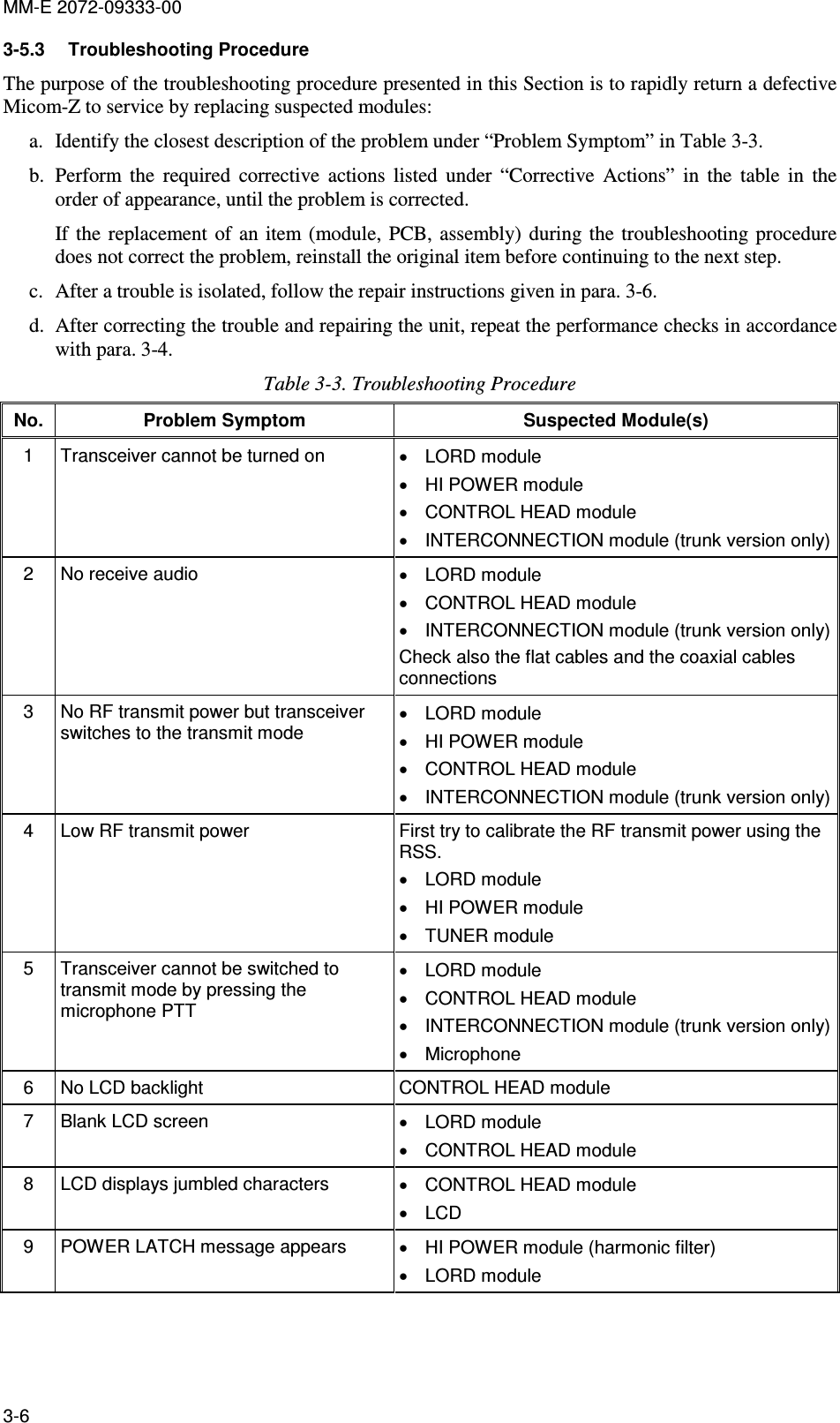
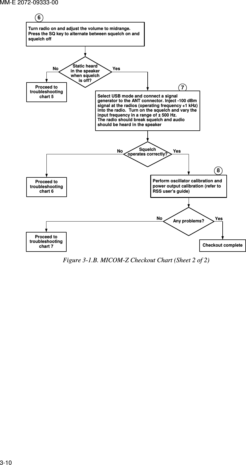
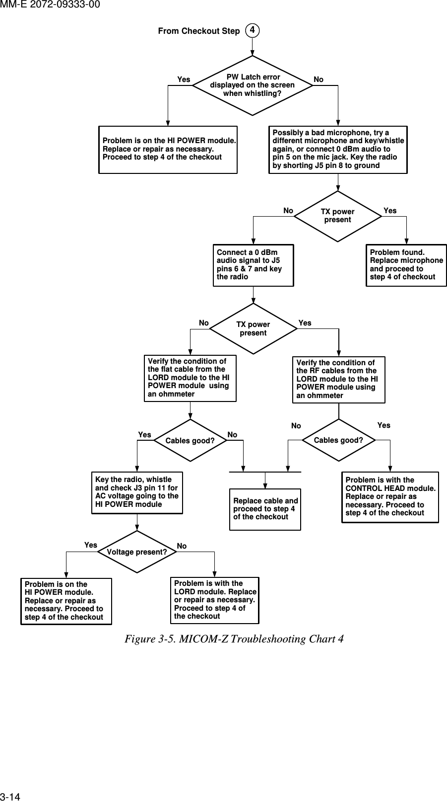
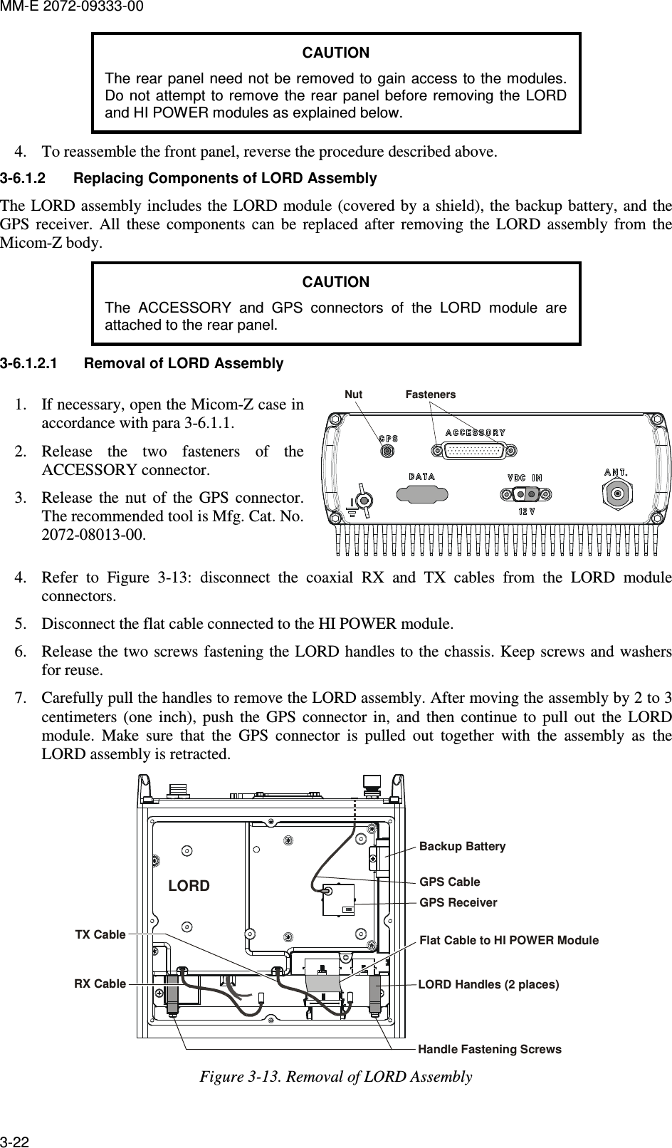
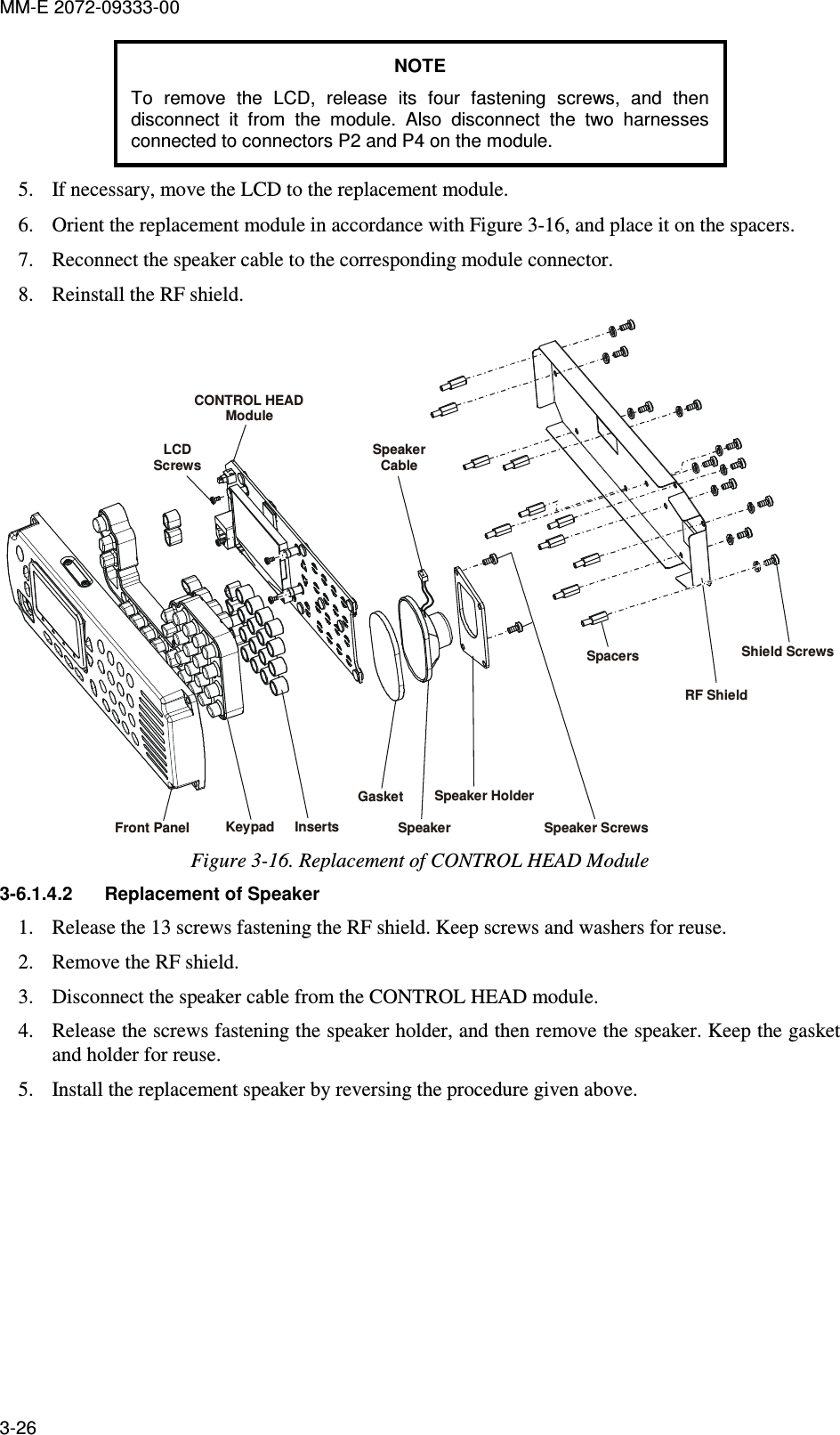
![MM-E 2072-09333-00 ~WR/P0.7~RD/P0.6ALE/P0.5P0.4P0.3P0.2P0.1~WR/P4.7~RD/P4.6ALE/P4.5P4.4P4.3P4.2P4.1A14/P5.6A13/P5.5A12/P5.4A11/P5.3A10/P5.2A9/P5.1A15M/A7/P6.7A14M/A6/P6.6A13M/A5/P6.5A12M/A4/P6.4A11M/A3/P6.3A10M/A2/P6.2A9M/A1/P6.1AD6/D6/P7.6AD5/D5/P7.5AD4/D4/P7.4AD3/D3/P7.3AD2/D2/P7.2AD1/D1/P7.1AD6/D6/P3.6AD5/D5/P3.5AD4/D4/P3.4AD3/D3/P3.3AD2/D2/P3.2AD1/D1/P3.1A14M/A6/P2.6A13M/A5/P2.5A12M/A4/P2.4A11M/A3/P2.3A10M/A2/P2.2A9M/A1/P2.1AIN2.6/A14/P1.6AIN2.5/A13/P1.5AIN2.4/A12/P1.4AIN2.3/A11/P1.3AIN2.2/A10/P1.2AIN0.6AIN0.5AIN0.4AIN0.3AIN0.2AIN0.1AIN0.0AIN0.7AIN2.7/A15/P1.7A8M/A0/P2.0AD0/D0/P3.0AD7/D7/P3.7AD0/D0/P7.0A8M/A0/P6.0A8/P5.0A15/P5.7AD7/D7/P7.7DAC0DAC1AIN2.1/A9/P1.1AIN2.0/A8/P1.0P0.0A15M/A7/P2.7TMSTDITDORSTTCKCP1+CP1-CP0-CP0+XTAL1XTAL2MONENDGND1AGND1AGND2P4.0VDD2VDD1VDD3AV+1AV+2VREFVREF0VREF2DGND2DGND3VREFDTACTIVE HIGHACTIVE HIGHGNDTCK3V3TDOTMSCPU_JTAGTDIACTIVE HIGHACTIVE HIGHREMAINS FROM INT0_NACTIVE HIGH = F(T,LED_ON)RESET_CPUACTIVE HIGHACTIVE HIGHACTIVE LOWACTIVE LOW1E8SH_DN_232_NTAD_CODAN_MODESH_DN_232_NTAD_CODAN_MODEON_OFF_SW10KR100R2512.1K3V3_CPU_ANRT1232261513103100NC555C554100N100NC5453V3_CPU3V3_CPU_ANTX_UART0_TTL100NC24C23100N555657585960619192939495969782838485868773747576777879666768697071484950515253404142434445303132333424232221201918252946544772808881651009935366239134527689262728381013986437901114121617638915U1C8051F126-GQ1E3TERMISTORTERM_M50V4.7UC15C164.7U50VC5514.7U50V50V4.7UC27100NC22C1410U25V25V10UC5523V33V3E502BLM18PG600SN1R531 0.00.06253V3_CPU3V3_CPU_ANR584 0.0100NC251E4V0_LCDXCS_N_SDFR37 1MBLM18PG600SN1E26RX_UART0_TTLRX_UART1_TTL100NC32A0_CPUMOSI_CPUXCS_N_LCDRST_N_LCDRD_N_CPUWR_N_CPUR105 10KR36 22.122.1R91R506 22.1LABCPU_D6CPU_D5CPU_D4CPU_D3CPU_D2CPU_D1CPU_D0CPU_D[7:0]CPU_D7C46100N16VR92 22.11TP501R21 22.122.1R2222.1R23R46 22.122.1R45R44 22.1R43 22.122.1R421E141E151E161E17 22.1R40R41 22.122.1R38R39 22.1C471U10V1E7R71 22.122.1R72ON_OFF_SWPOW_OFF_CPUPTT_MIC_P_CPUPTT_MIC_NVLED_HEAT_ENKB_BL_ENRX_UART0_TTLSCL_CPUR80 22.1LCD_HEAT_LEVELLCD_BL_LEVELLCD_BL_ENR19 22.1RX_UART1_TTLTX_UART1_TTL0.0R82R83 0.00.0R84R85 0.00.0R86R81 0.010KR12198765432101TSW-105-23-S-DP51E21E11E91E5R49 22.1R18100KR171K12P7TSW-102-23-S-SR212 221KC121100N1E251E24KEY_X0KEY_X1KEY_X4KEY_X[4:0]KEY_Y0KEY_Y[4:0]22.1R63R120 10K10KR11910KR98R99 10KR93 10K22.1R223R222 22.122.1R54R115 22.1Y17.3728MHZ33PC19MISO_CPU22.1R261E211E2222.1R65R8710KR107 10K10KR10622.1R116R114 22.122.1R117TCK_CPU3V3_CPUR62 22.1R51 22.1100NC26C2033P22.1R33R32 22.1R31 22.122.1R3022.1R29R28 22.1R27 22.13V3_CPUR47 22.122.1R4822.1R5022.1R52R53 22.122.1R61R60 22.1R59 22.1R58 22.122.1R5722.1R5622.1R55R70 22.1R69 22.1R68 22.122.1R6722.1R66R64 22.1R74 22.1R73 22.1R76 22.1R75 22.1R78 22.1R77 22.1R79 22.13V3_CPU10KR1083V3_CPUR109 10K10KR1101E23TDO_CPU3V3_CPUTMS_CPUTDI_CPU3V3_CPU10KR94R95 10K10KR96R97 10KR118 10K10KR113R112 10K10KR111R104 10K10KR103R102 10K10KR10122.1R20R24 22.122.1R34R35 22.122.1R88R89 22.122.1R90KEY_Y3KEY_Y2KEY_Y1KEY_X3KEY_X2C45100N1E101E113V3_CPU1E321E361E351E33PTT_MIC_P_CPUXCS_N_SDFXIL_MONITOR3V3SDF_SW_DETTX_UART1_TTLKEY_X[4:0]KEY_Y[4:0]CPU_D[7:0]WR_N_CPURST_N_LCDXCS_N_LCDRD_N_CPUSCL_CPUMOSI_CPUV0_LCDMISO_CPUXIL_MONITORLCD_HEAT_LEVELLCD_BL_LEVELLCD_BL_ENKB_BL_ENSDF_SW_DETVLED_HEAT_ENLCD_HEAT_ENKEY_Y4C553100NTX_UART0_TTLLCD_HEAT_ENA0_CPU1NC5500.06250.0R532C5444.7U50VTCK_CPUTDO_CPUTDI_CPUTMS_CPUMR_NV0_LCD_DIV3V3_CPU_ANPOW_OFF_CPU Figure A-3.B. CONTROL HEAD Module, Schematic Circuit Diagram (Sheet 2 of 6 – Microcontroller) A-53/A-54](https://usermanual.wiki/Elbit-Systems-Land-and-C4I-Tadiran/MICOM-TRK125W.Service-Manual/User-Guide-2016167-Page-103.png)
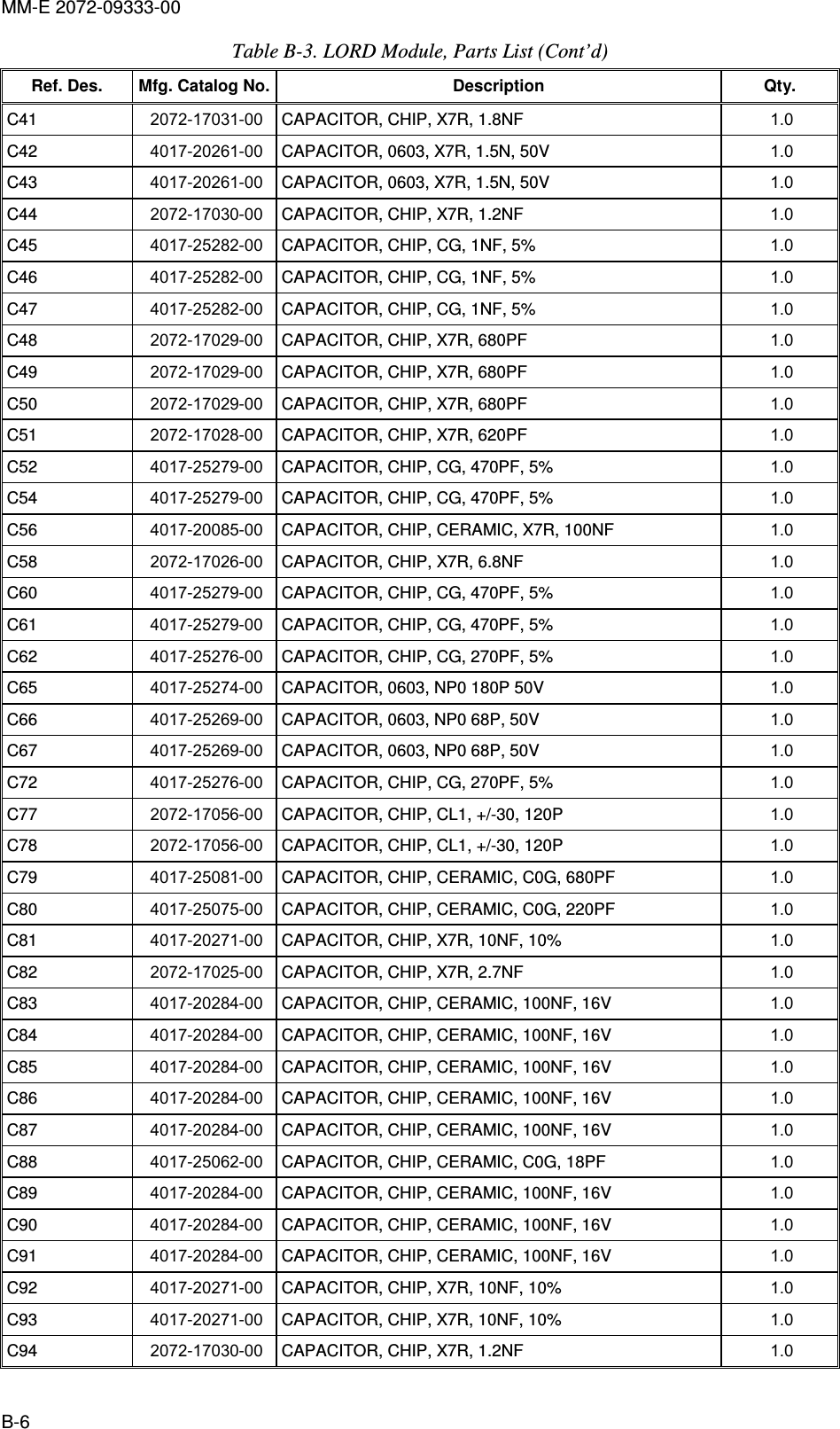
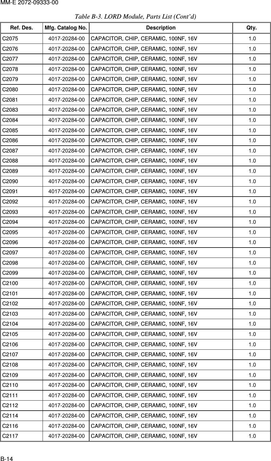
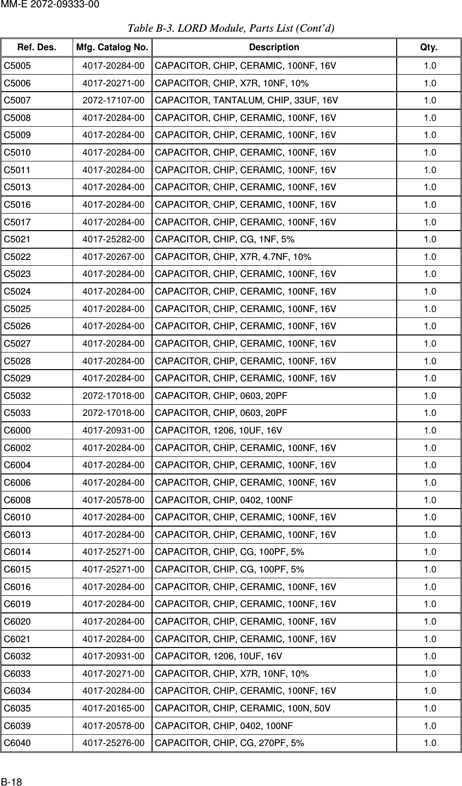
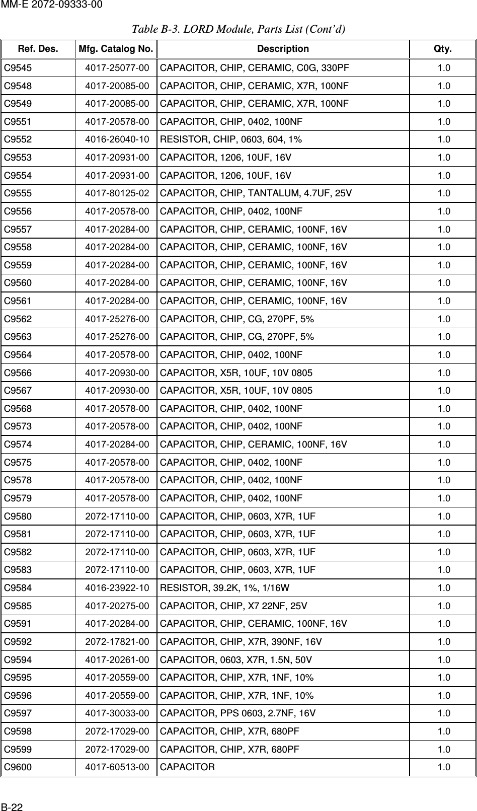
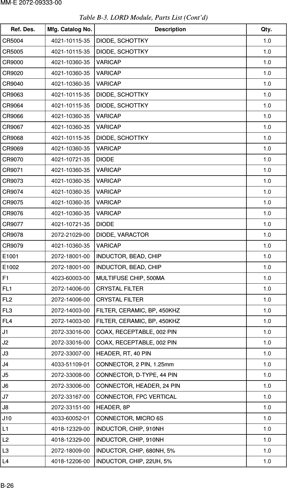
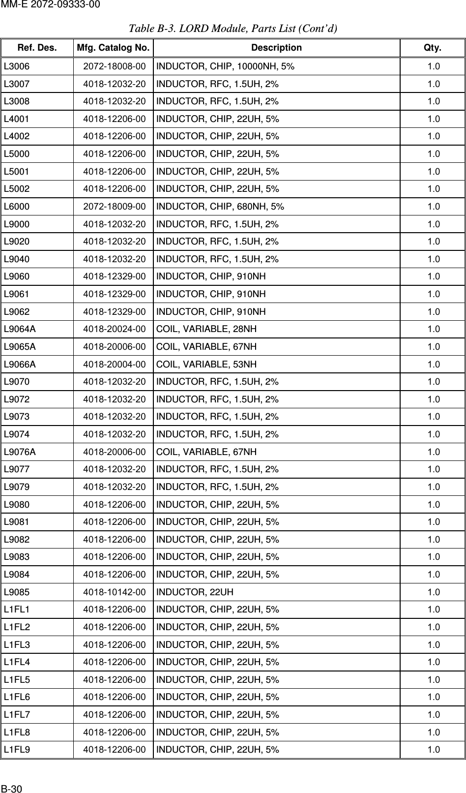
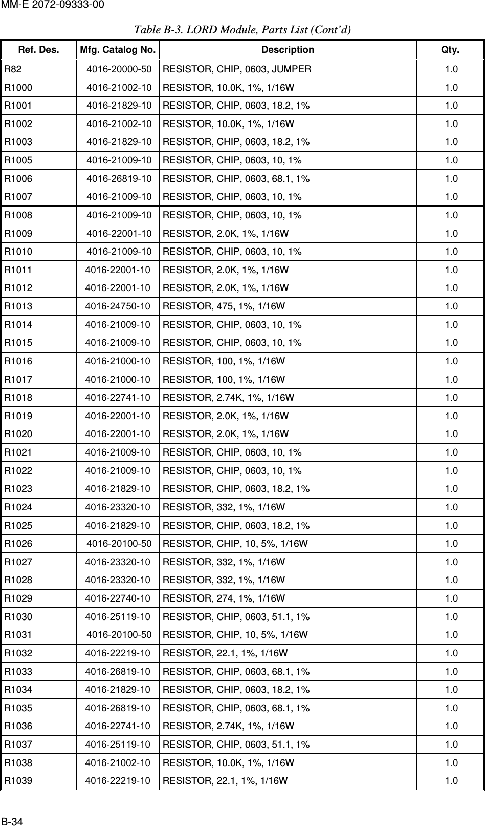
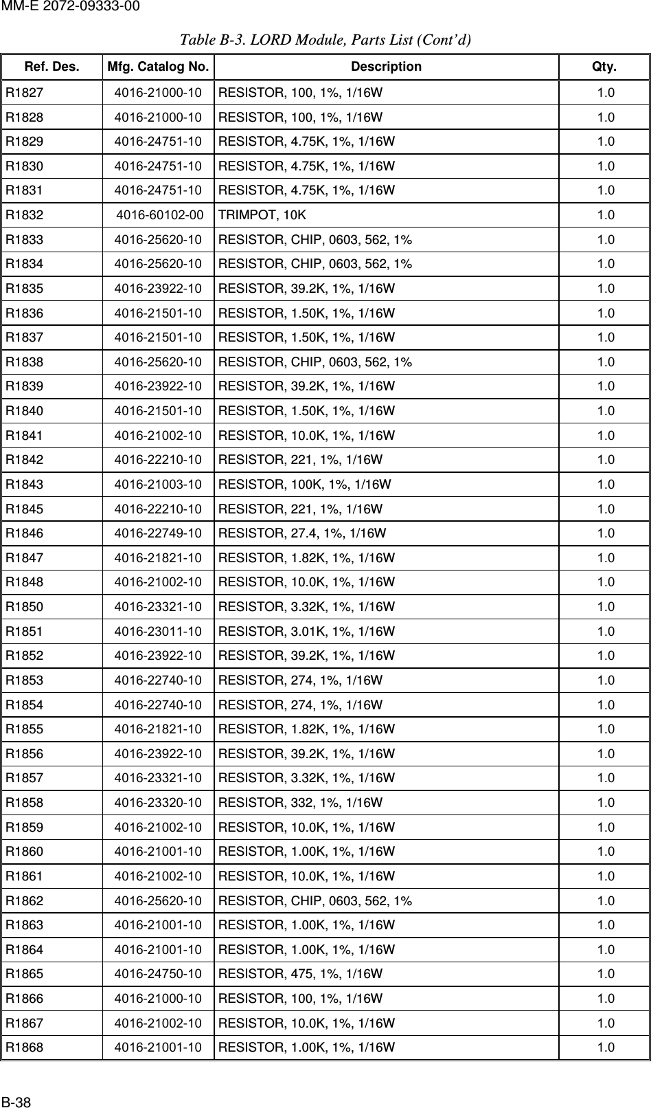
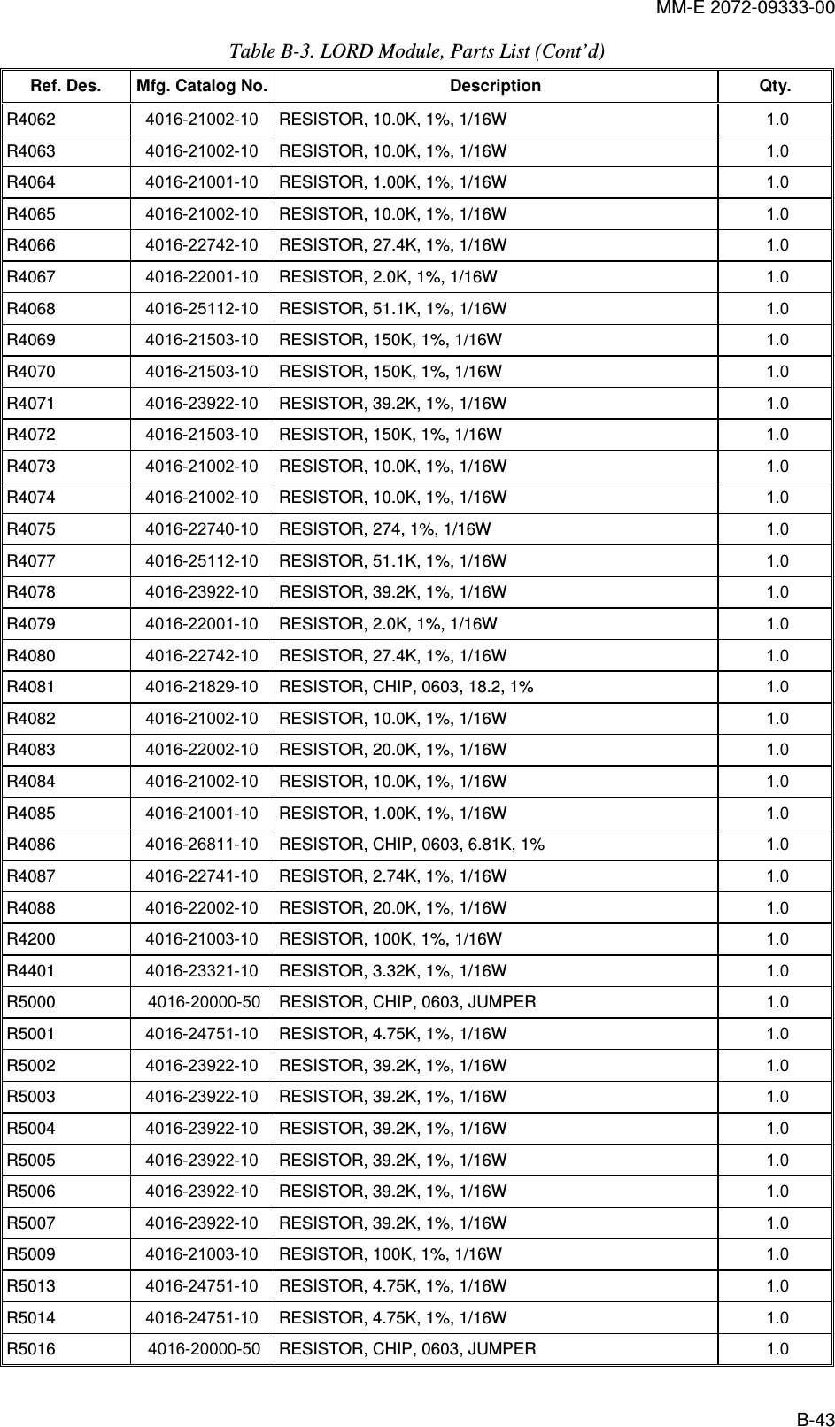
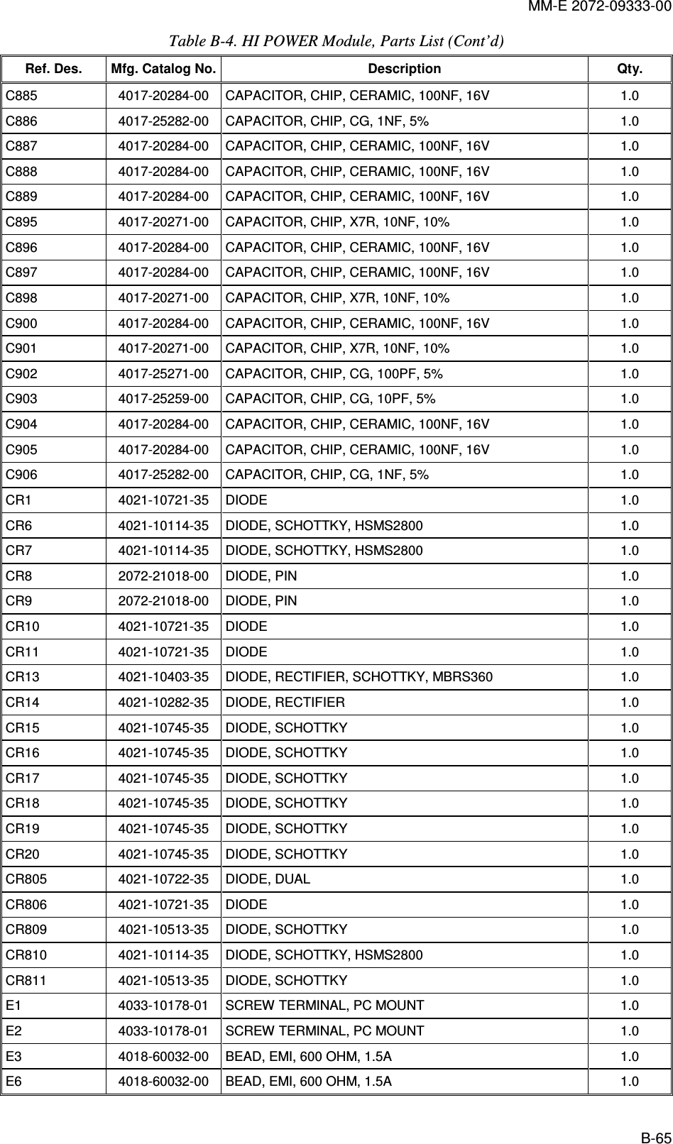
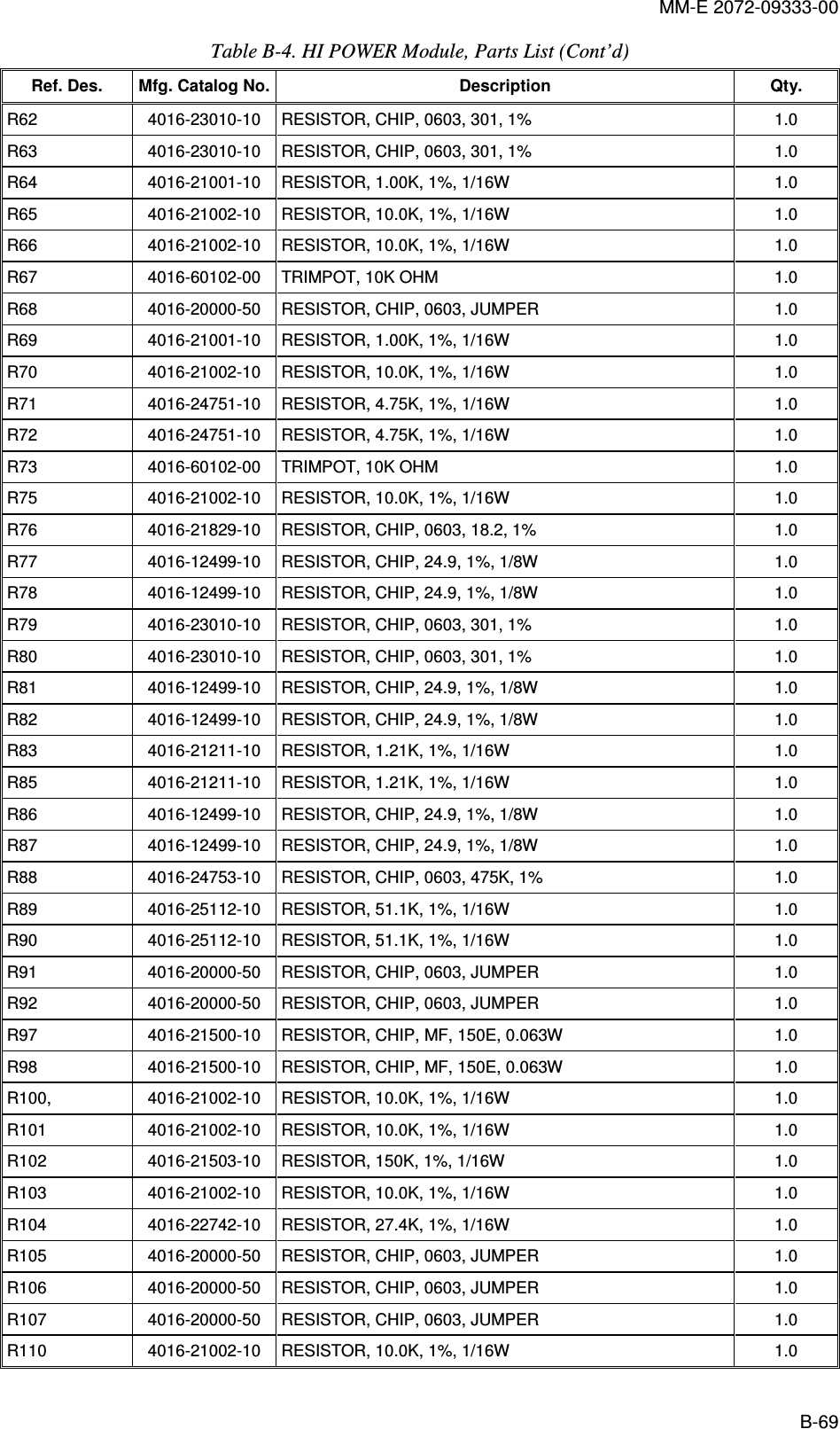
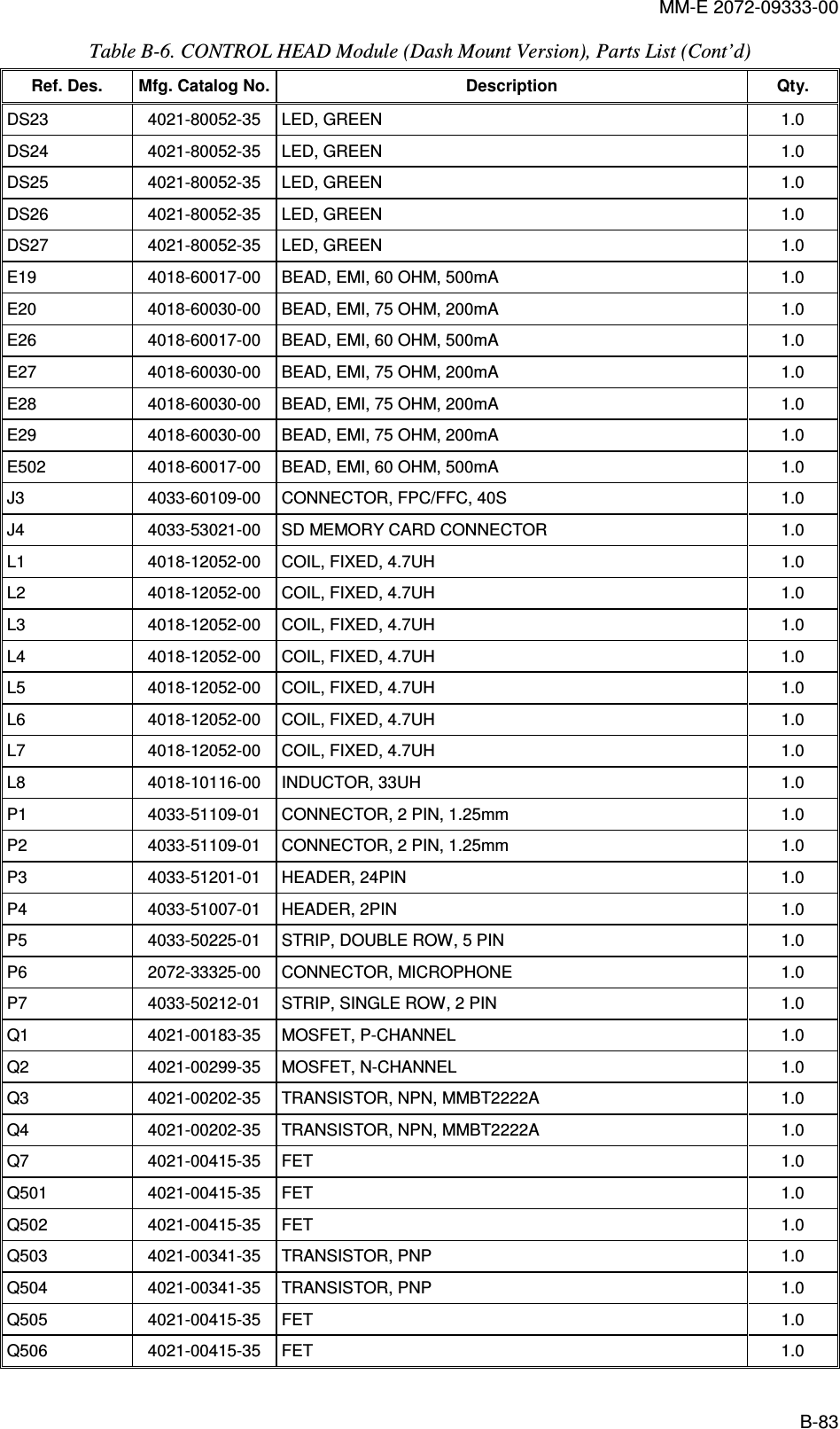
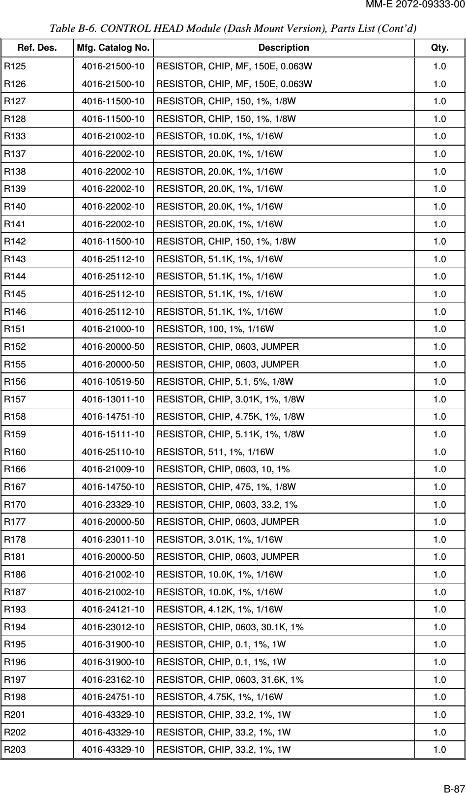
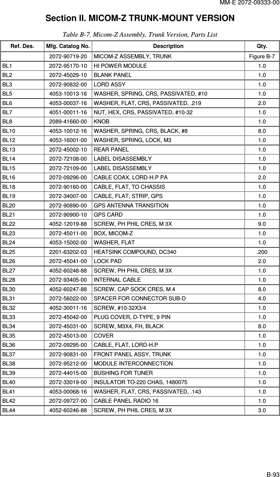
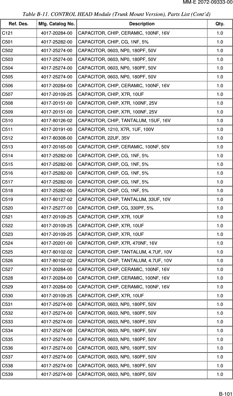
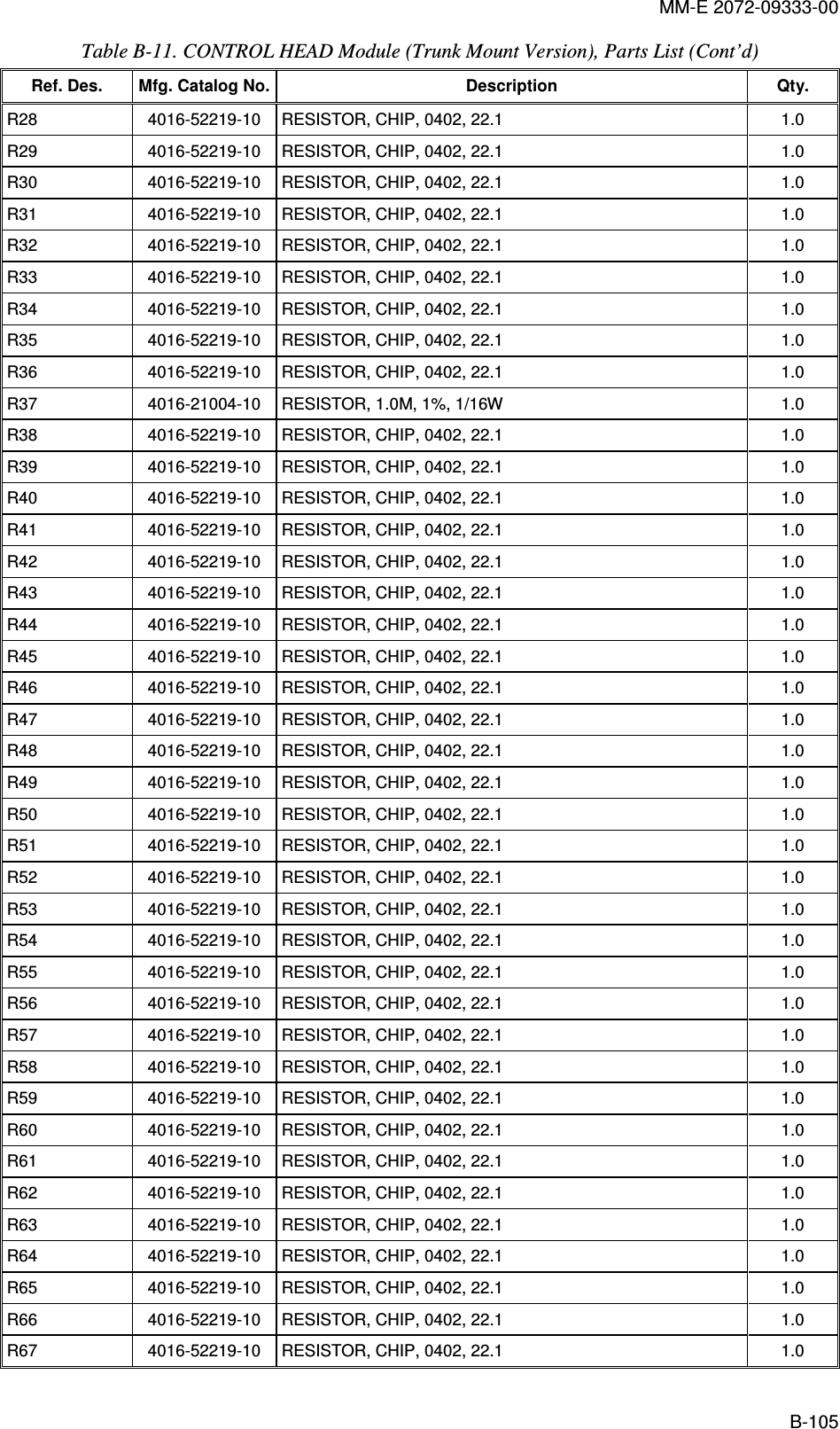
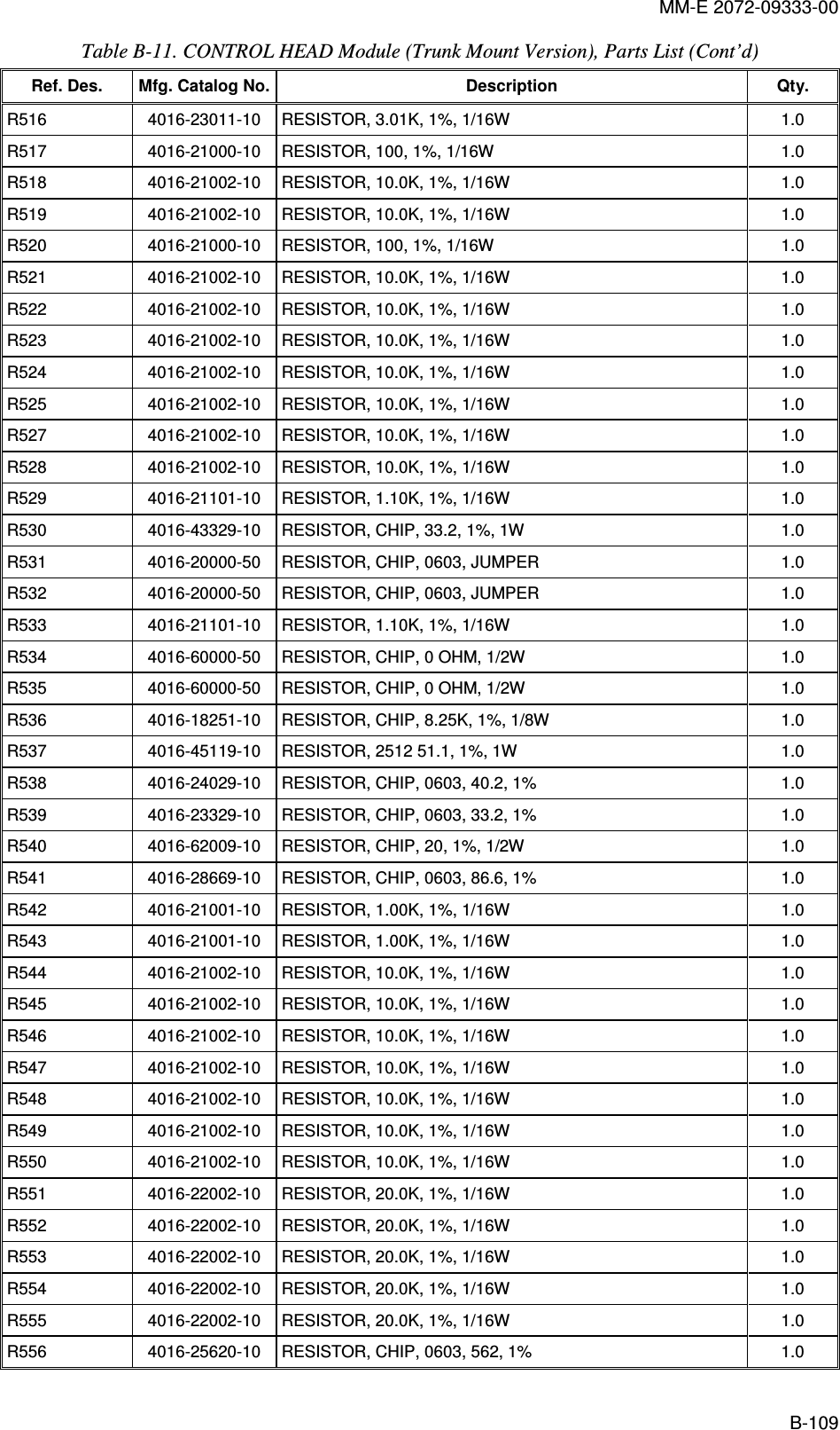
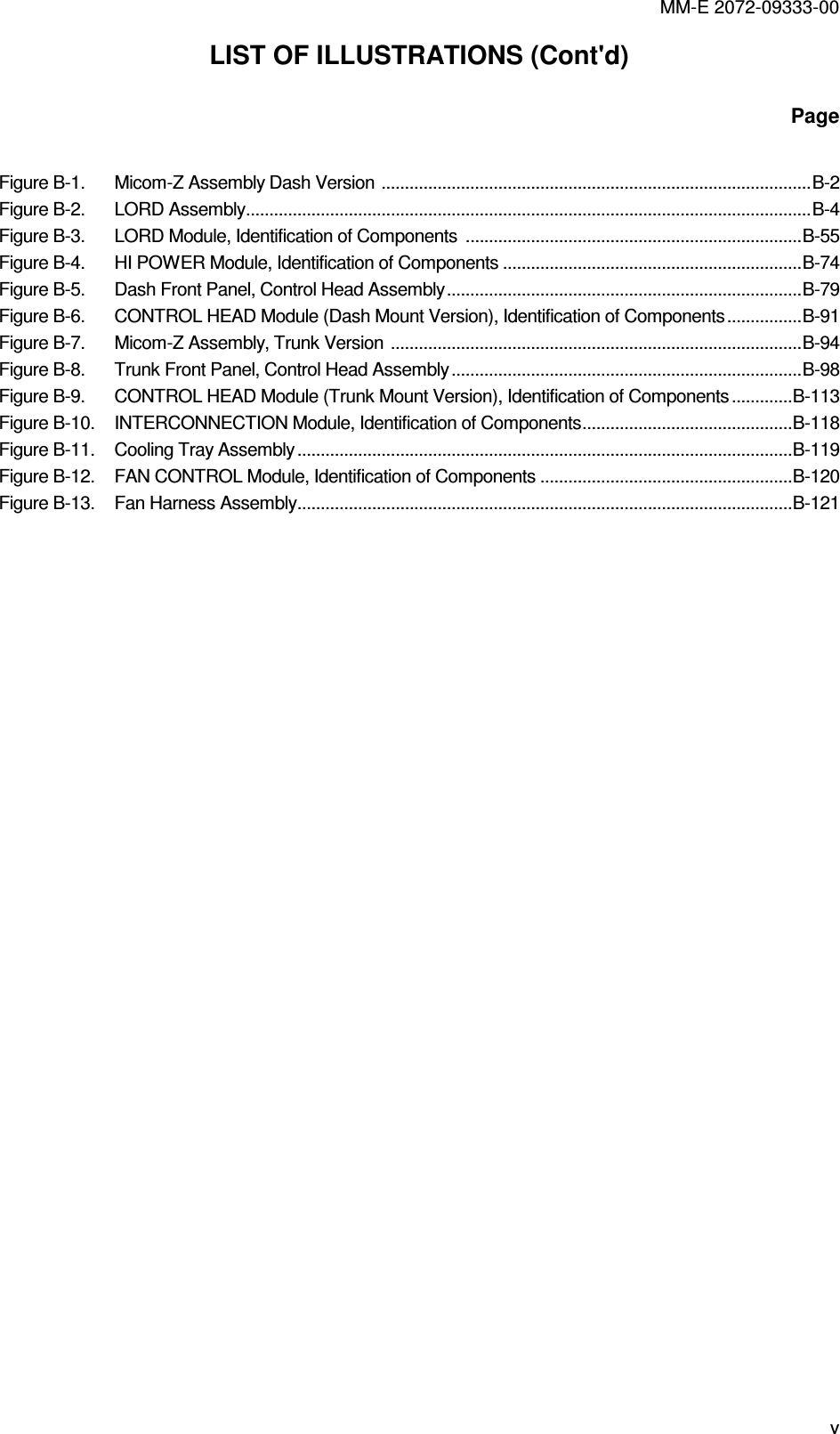
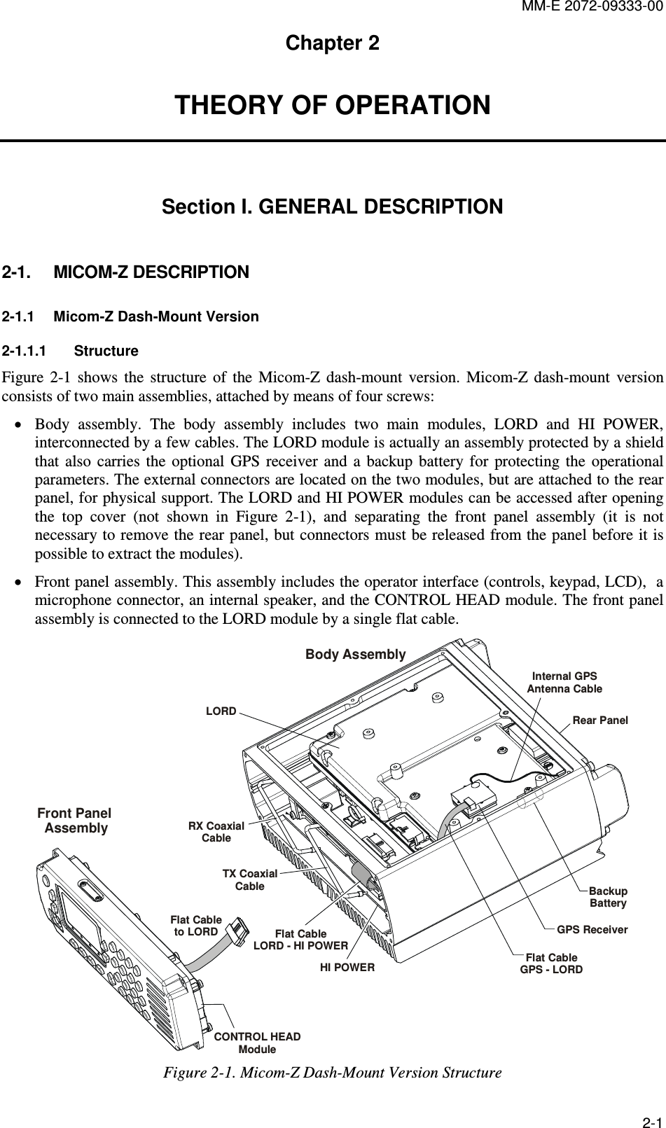
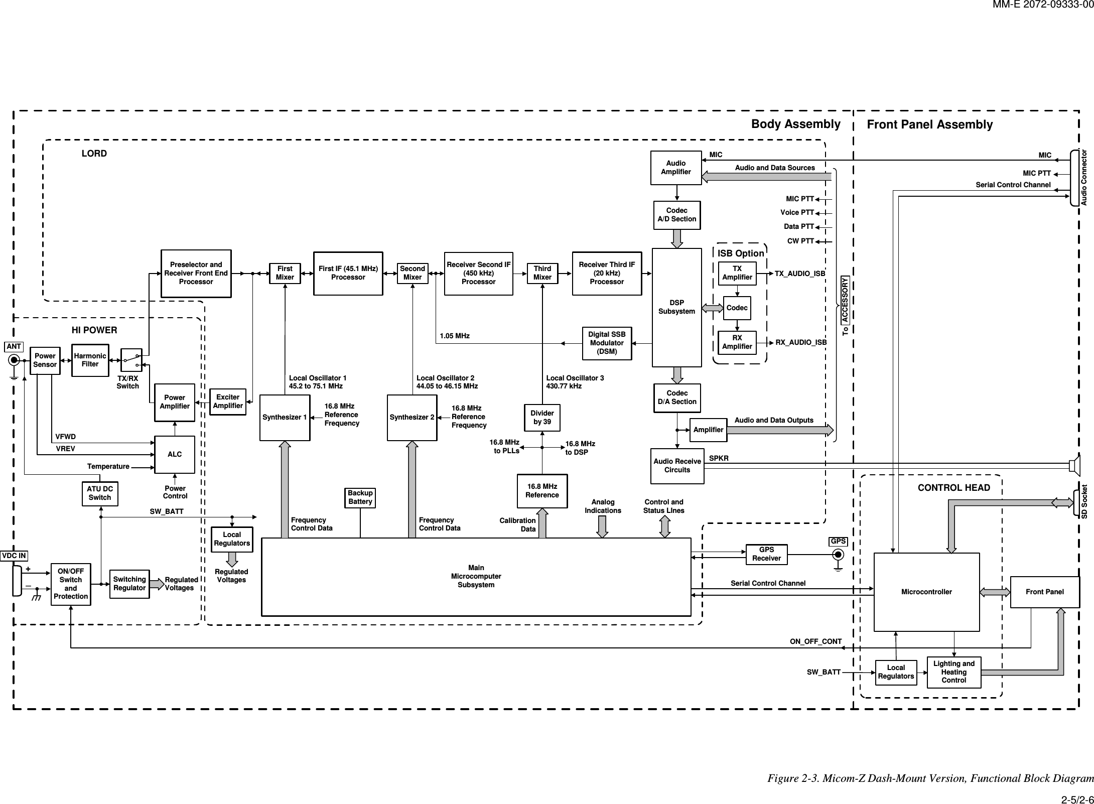
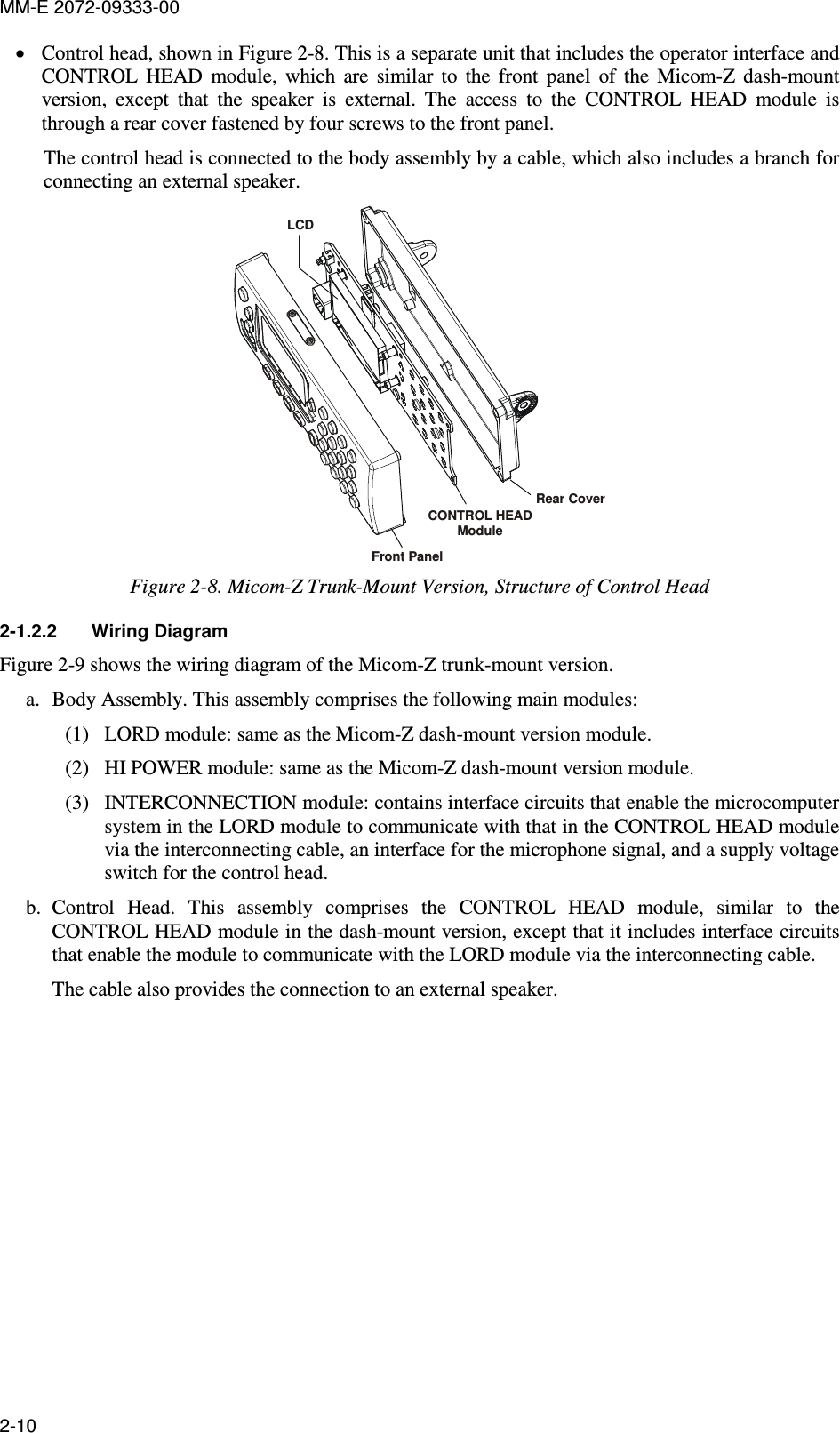
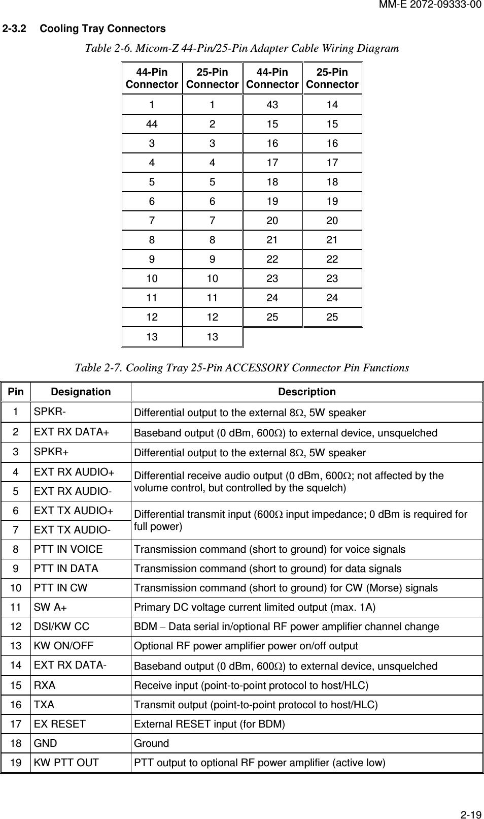
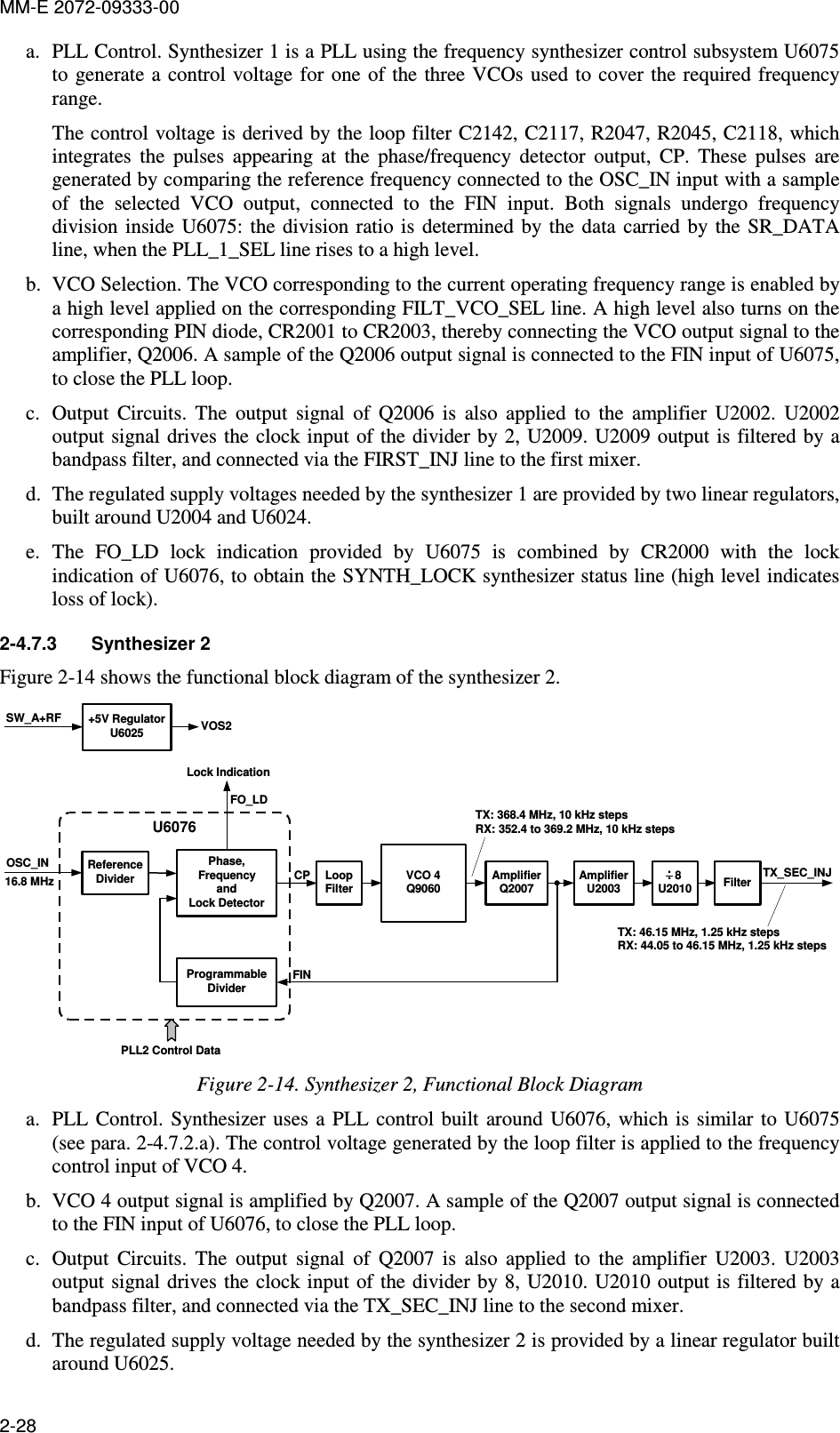
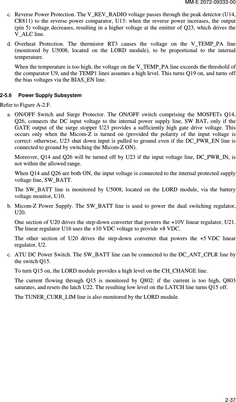
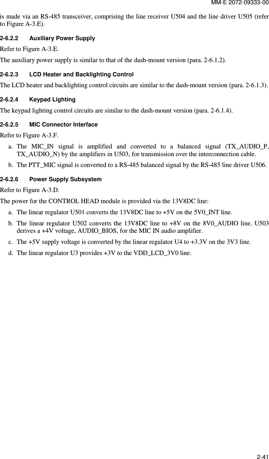
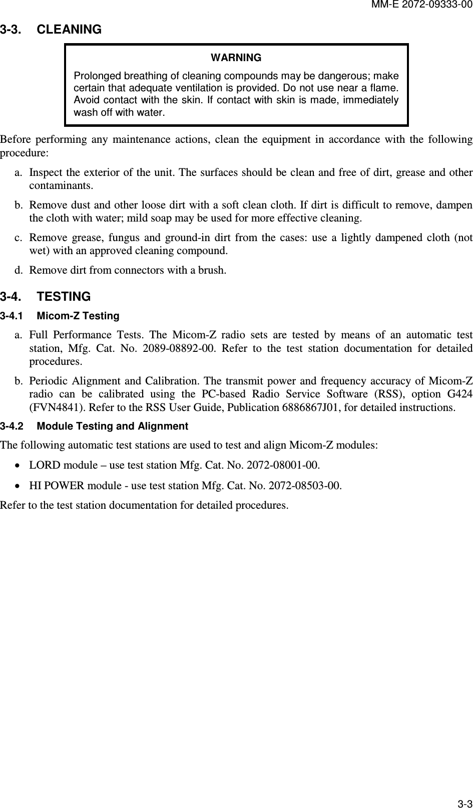
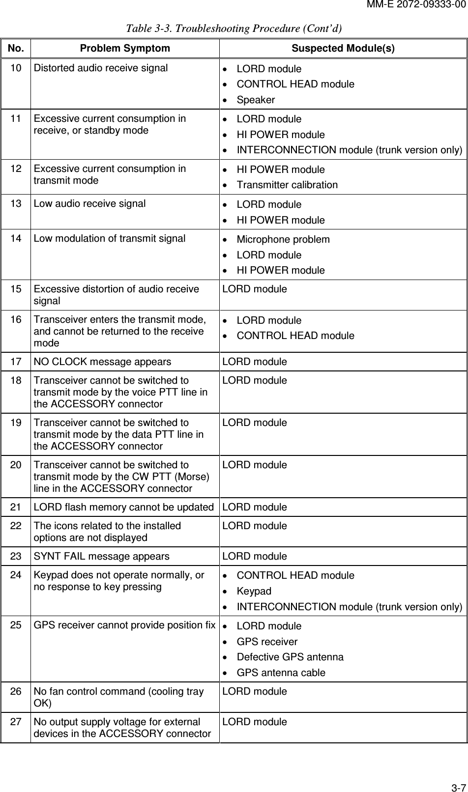
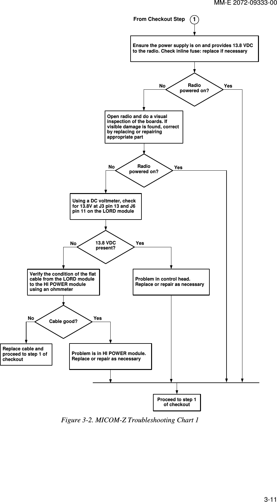
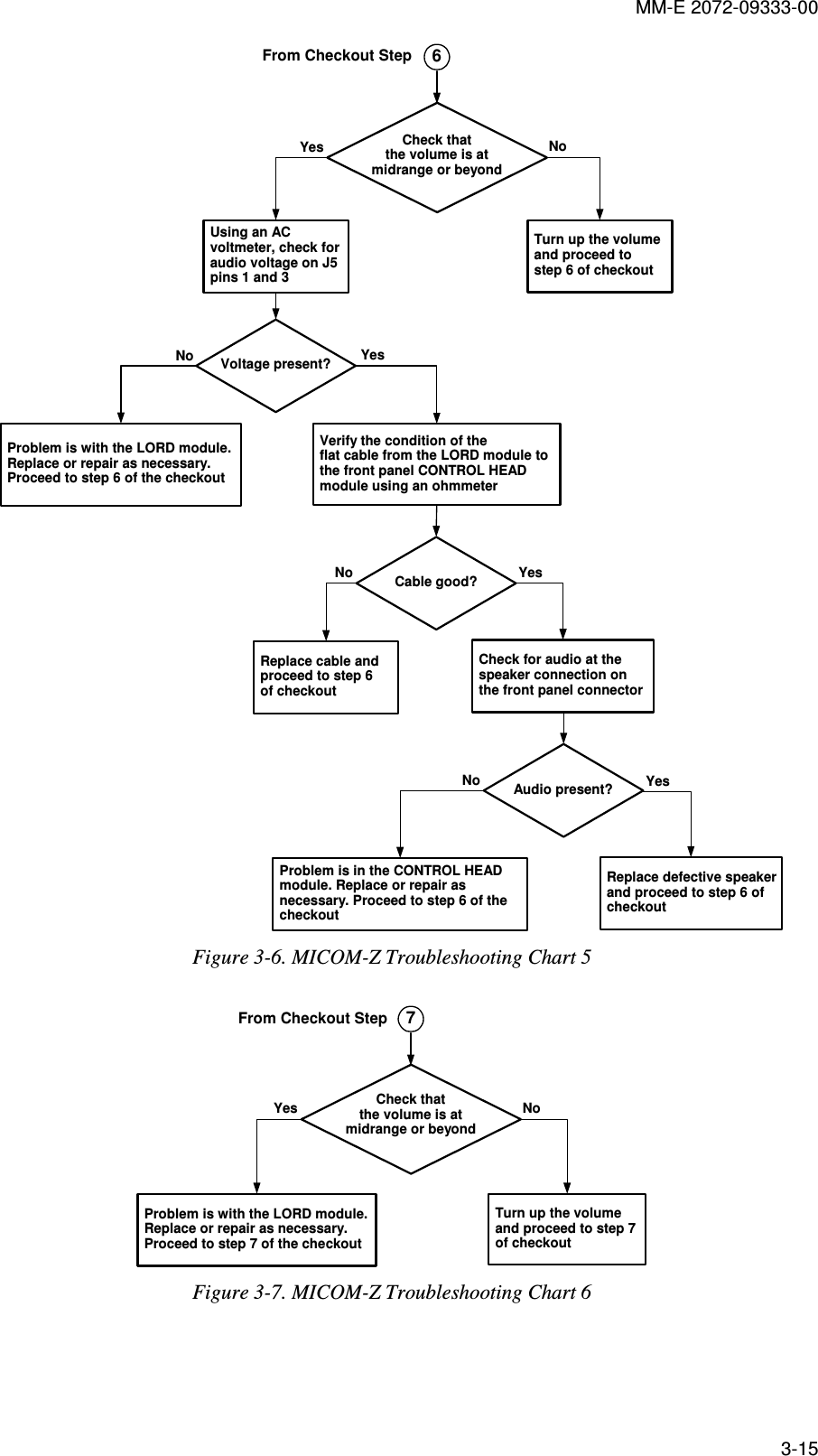
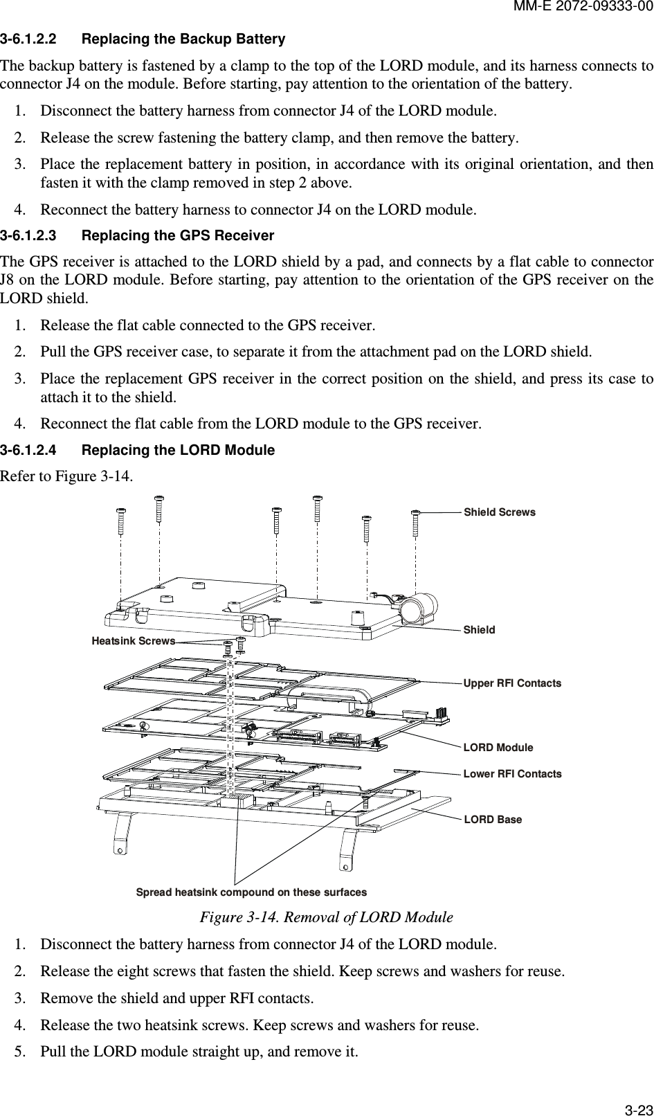
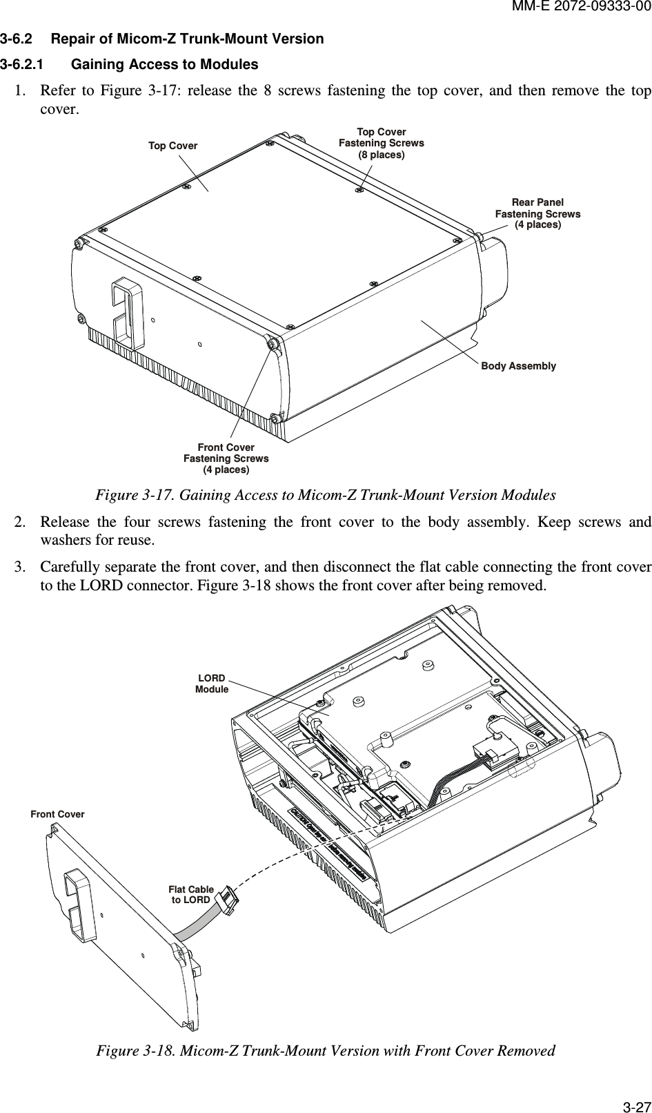
![MM-E 2072-09333-00 GND10GND9GND8GND7GND5GND2DAT1DAT0VSSCLKVDDCMDDAT2CD/DAT3GND1GND6+-+-+-+-+-+-+-+-+-+-KEYPADPAD61 2 3 4 5ENTER VOL_UPPAD2VOL_DNPAD26 7 8 9 0M P * GPS #PAD6F1 F2 F3 F4PAD4PAD6PAD6 !!!ARRUPPAD3ARRDNPAD3MOREPAD54V331MMBZ5229BLT1VR50613VR505MMBZ5229BLT131MMBZ5229BLT1VR50413VR503MMBZ5229BLT131MMBZ5229BLT1VR502KEY_Y3KEY_Y2KEY_Y113VR507MMBZ5229BLT131MMBZ5229BLT1VR50813VR509MMBZ5229BLT131MMBZ5229BLT1VR51013VR511MMBZ5229BLT1R122150C544.7U50V3V3C5310U25V150R123R124150150R125R12615012111091514876543121316J4DM3A-SF-PEJ100NC59R5291.10KR5331.10KR5631.10KR5691.10KR5831.10KKEY_X0KEY_X1KEY_X2KEY_X3R14120K20KR140R13920K20KR138R13720KKEY_X[4:0]3V3_IF1234SW25PAD_SW_KEY21234SW24PAD_SW_KEY21234SW23PAD_SW_KEY6654321PAD_SW_KEY3SW22123456SW21PAD_SW_KEY34321PAD_SW_KEY5SW204321PAD_SW_KEY4SW194321PAD_SW_KEY4SW184321PAD_SW_KEY4SW174321PAD_SW_KEY4SW164321PAD_SW_KEY6SW154321PAD_SW_KEY6SW104321PAD_SW_KEY6SW54321PAD_SW_KEY6SW44321PAD_SW_KEY6SW94321PAD_SW_KEY6SW144321PAD_SW_KEY6SW134321PAD_SW_KEY6SW84321PAD_SW_KEY6SW34321PAD_SW_KEY6SW24321PAD_SW_KEY6SW74321PAD_SW_KEY6SW124321PAD_SW_KEY6SW114321PAD_SW_KEY6SW61234SW1PAD_SW_KEY63V3_IF3V3_IF3V3_IF100PC61C62100P3V3_IF3V3_IF100PC64 C63100P3V3_IFC65100PR13310KR146 51.1KE29BLM18BB750SN1D22PC69C6822PC6722P22PC66R148 OPTIONR147OPTION51.1KR145R144 51.1KBLM18BB750SN1D E28E27BLM18BB750SN1DBLM18BB750SN1D E2051.1KR143SDF_SW_DETSCL_CPUMOSI_CPUXCS_N_SDFMISO_CPUKEY_Y03V3_IF3V3_IF100NC60BLM18PG600SN1E19KEY_Y[4:0]KEY_Y4KEY_X414V7R233 41.21 2DS12KPT-1608CGCK-RY1 2DS13KPT-1608CGCK-RY150R128R127 150150R142VLED_BL_KB1 2DS1KPT-1608CGCK-RY1 2DS14KPT-1608CGCK-RY1 2DS20KPT-1608CGCK-RY1 2DS8KPT-1608CGCK-RY1 2DS2KPT-1608CGCK-RY1 2DS15KPT-1608CGCK-RY1 2DS21KPT-1608CGCK-RY1 2DS9KPT-1608CGCK-RY1 2DS3KPT-1608CGCK-RY1 2DS4KPT-1608CGCK-RY1 2DS10KPT-1608CGCK-RY1 2DS16KPT-1608CGCK-RY1 2DS22KPT-1608CGCK-RY1 2DS5KPT-1608CGCK-RY1 2DS11KPT-1608CGCK-RY1 2DS23KPT-1608CGCK-RY1 2DS17KPT-1608CGCK-RY1 2DS6KPT-1608CGCK-RY1 2DS18KPT-1608CGCK-RY1 2DS24KPT-1608CGCK-RY1 2DS7KPT-1608CGCK-RY1 2DS19KPT-1608CGCK-RY1 2DS25KPT-1608CGCK-RY Figure A-3.C. CONTROL HEAD Module, Schematic Circuit Diagram (Sheet 3 of 6 – Keypad) A-55/A-56](https://usermanual.wiki/Elbit-Systems-Land-and-C4I-Tadiran/MICOM-TRK125W.Service-Manual/User-Guide-2016167-Page-104.png)