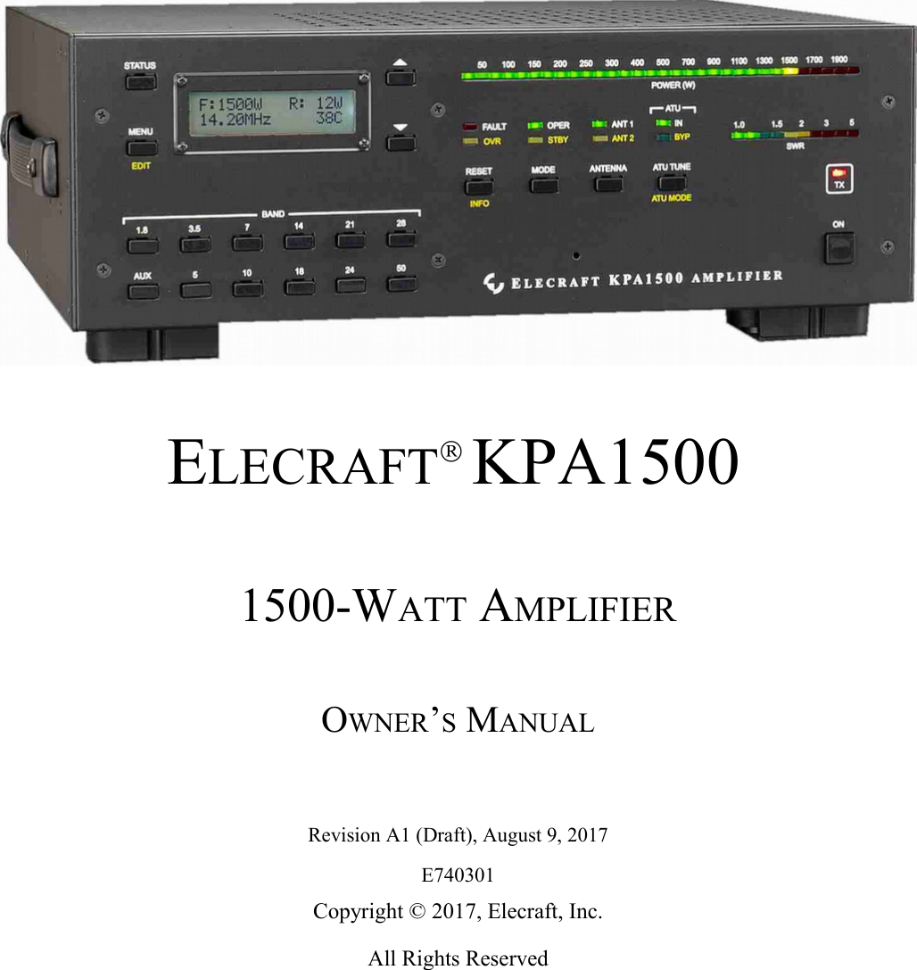
Elecraft KPA1500 Amateur Radio External Linear Amplifier User Manual KPA500 Owner s Manual
Elecraft, Inc. Amateur Radio External Linear Amplifier KPA500 Owner s Manual
UserManual.wiki
>
Elecraft
>
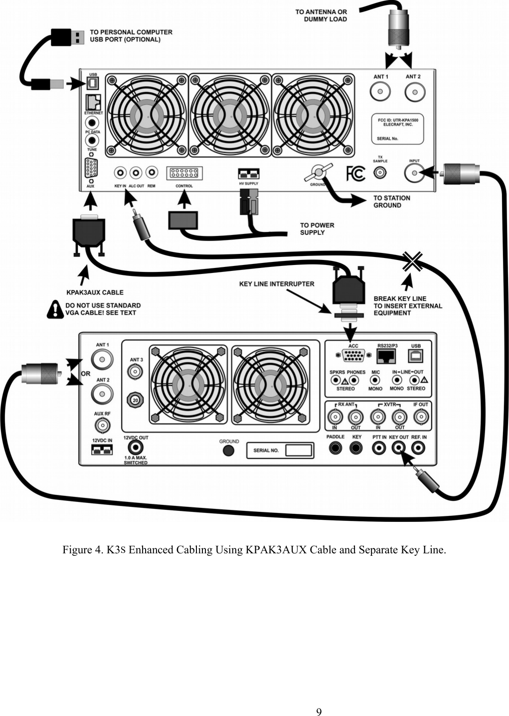
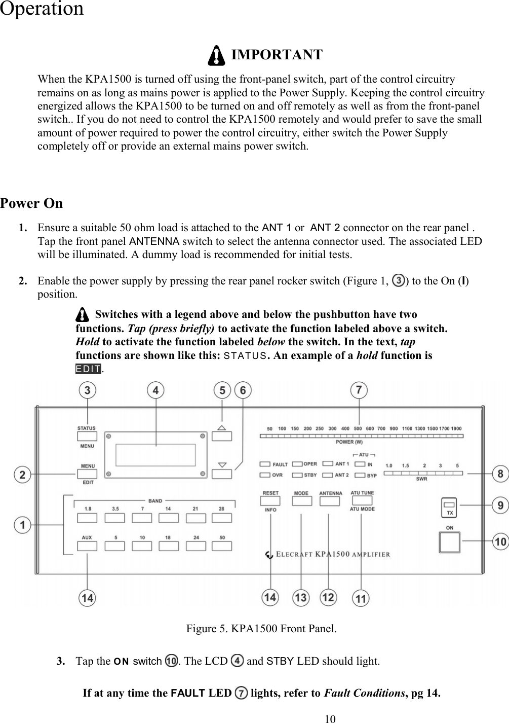
KPA1500 User Manual
Users Manual Revised
Navigation menu
Upload a User Manual
Namespaces
Wiki Guide
HTML
PDF
Info
Views
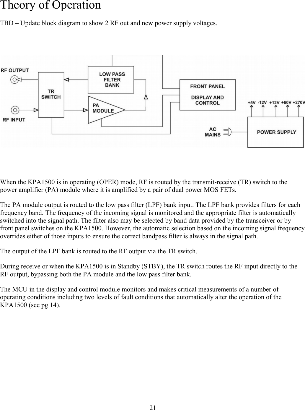
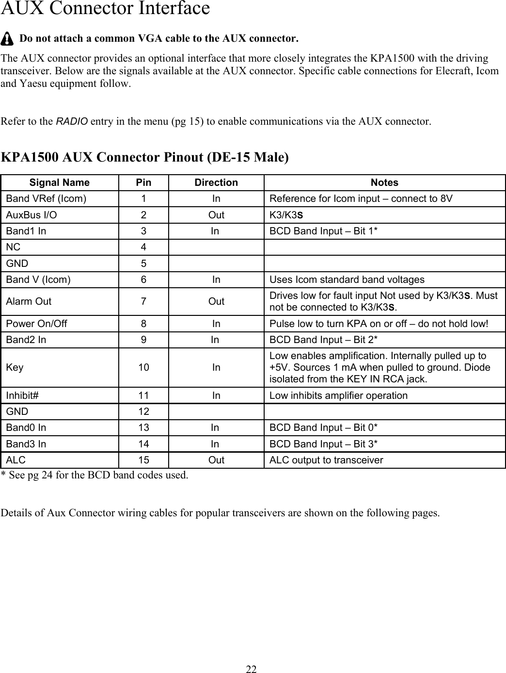
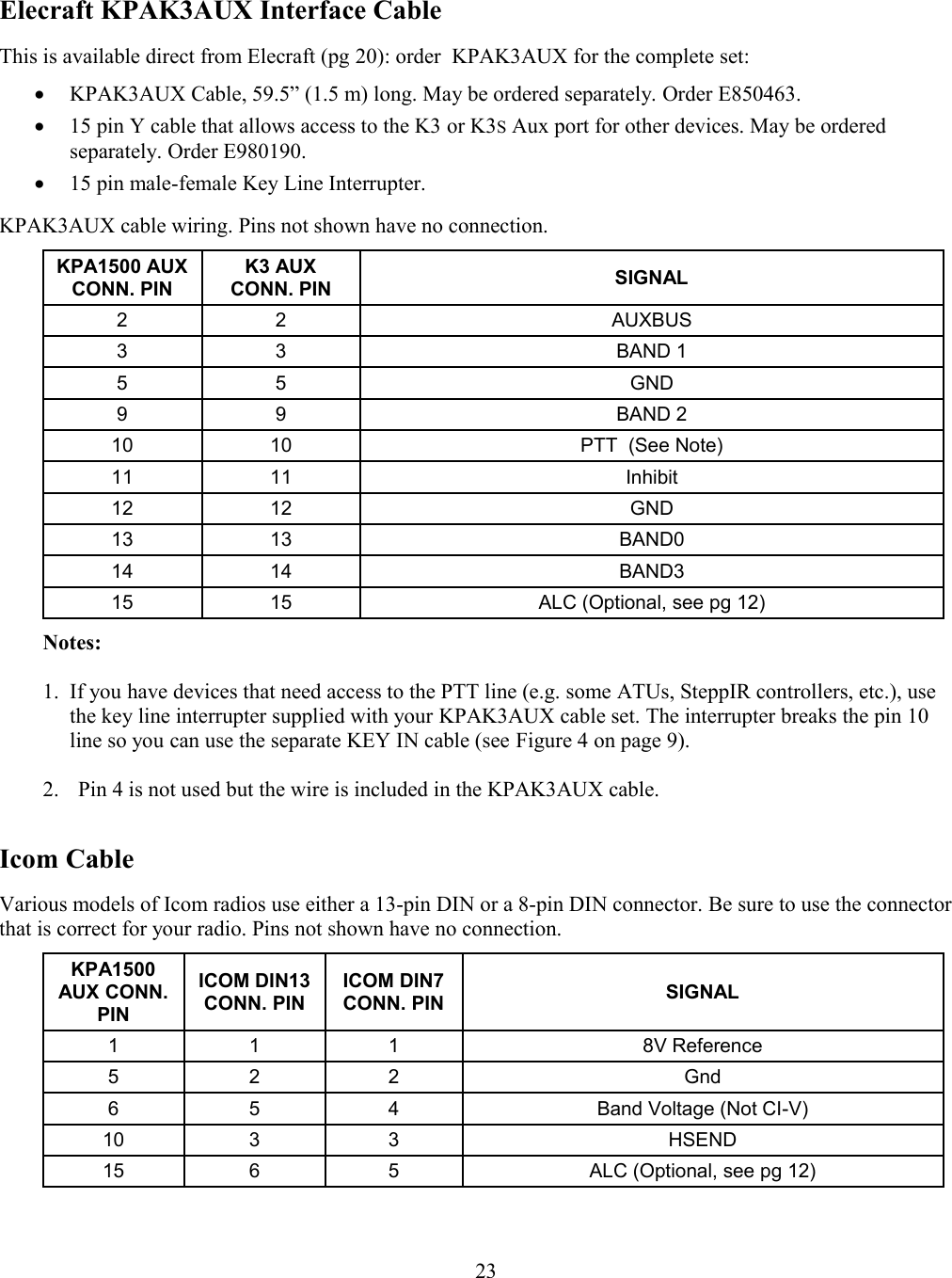
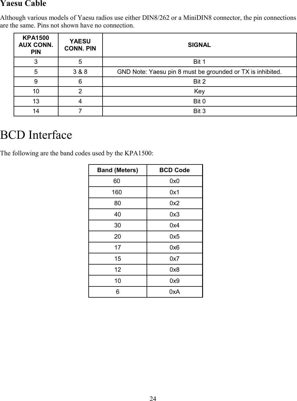
User Manual
Discussion / Help
Navigation