Electricity Metering B A001SC42 ALPHA meter User Manual
Electricity Metering, ABB Inc ALPHA meter
User Manual

ABB Inc. IL42-4027A
Electricity Metering
208 South Rogers Lane
Raleigh, NC 27610 USA
Customer Support: +1 800 338 5251
JUNE 2002 Fax: +1 919 212 4717
Installing an ALPHA® Meter / Internal
Cellular Modem
General
ABB’s ALPHA meter is available with options that allow communicating over the
Advanced Mobile Phone System (AMPS) and the Public Switched Telephone Network
(PSTN). This leaflet contains procedures for installing an ALPHA meter with the
Internal Cellular Modem (ICM) option to provide a standard interface for data
communications using the AMPS / PSTN. For information on installing the meter itself,
see the instructional leaflet that pertains to the type of meter you have.
Use authorized utility procedures to install and service metering equipment.
Dangerous voltages are present. Personal injury, death, or equipment
damage can result if safety precautions are not followed.
Use circuit closing devices on any current transformer secondaries (Form 35S
(5S), 35A (5A), 36S (6S), 36A (6A), 9S, 10A meters). Personal injury, death, or
equipment damage can result if circuit closing devices are not used.
The remotely–readable ALPHA meter with the ICM option does not normally require
any wiring for meter communications. The use of an external antenna does require
additional wiring; however, when using the internal antenna, no wiring to support
communications is required.
For more information on remote operation of ALPHA meters, see ALPHA Meter Options:
Enhanced Metering Functions, Relays, and Modems (TM42-2181B or later), ALPHA Plus
Meter Technical Manual (TM42-2182C or later), or A3 ALPHA Meter Technical Manual
(TM42-2190A or later). These manuals include instructions on retrofitting a meter to
operate with a landline modem and information on programming, reading, and testing
the meter for remote operation over the telephone lines.
Regulatory Information
NOTE: This equipment has been tested and found to comply with the limits for a Class B digital device,
pursuant to part 15 of the FCC Rules. These limits are designed to provide reasonable protection against
harmful interference in a residential installation. This equipment generates, uses and can radiate radio
frequency energy and, if not installed and used in accordance with the instructions, may cause harmful
interference to radio communications. However, there is no guarantee that interference will not occur in a
particular installation. If this equipment does cause harmful interference to radio or television reception,
which can be determined by turning the equipment off and on, the user is encouraged to try to correct the
interference by one or more of the following measures:
£ Reorient or relocate the receiving antenna.
£ Increase the separation between the equipment and receiver.
£ Connect the equipment into an outlet on a circuit different from that to which the receiver is connected.
£ Consult the dealer or an experienced radio/TV technician for help.

IL42-4027A JUNE 2002
2
If you experience trouble with this equipment, please contact ABB’s RMR Department at +1 919 212 4700.
Do not attempt to repair this equipment yourself unless you are replacing an entire module.
Performing a BER Test on the ICM Connection
Once the Alpha Meter with ICM is installed, it is recommended that the meter installer
perform an installation test using ABB’s metercat software (rev 1.2 or later). This test
validates the quality of the communication link using a combination of two measurements:
The measured Received Signal Strength Indicator (RSSI).
A Bit Error Rate (BER) measurement with a remote digital loop back device using
the V.54 Standard.
The thresholds related to those measurements (successful RSSI threshold, successful BER
threshold, duration of the BER measurement…) can be changed from the recommended
default values in the ABB metercat software. If both measurements are successful according
to the pre-defined set of thresholds, the installation test will be reported as being successful.
The test procedure is as follows:
1. Connect the optical probe to the meter under test, and select the optical probe connection
in metercat. This test will be performed via optical connection only
2. The pre-defined function named “Test ICM” must be selected
3. A window called “Test Cellular Modem Task Run Time Overrides” will be shown on the
screen displaying all the parameters values related to this test. Depending on the test
set-up, some of those parameters can be overridden at program execution time. Please
consult the Metercat user guide for more details. Once the user selects OK on this
window the test will run
4. A completion report will be displayed with “passed” or “failed” as well as additional test
results (RSSI measured, BER measured…)
Connecting an External Antenna to the ALPHA Meter / ICM For
Use With An External Antenna
At times the meter may be installed in a service cabinet, or in a location where the RF signal
is greatly attenuated due to physical obstructions, or simply the distance from the nearest
cellular tower is too great to achieve sufficient signals for reliable data communications. The
ALPHA meter provides a means such that an external antenna can be used to enhance
communications between the tower and the meter while providing 4 kV of voltage isolation at
60 hertz.
To ensure compliance with FCC RF exposure requirements, the antenna used
for this device must be installed to provide a separation distance of at least
20 cm from all persons and must not be co-located or operating in
conjunction with any other antenna or radio transmitter. Installers and end-
users must follow the installation instructions provided in the users guide.

JUNE 2002 IL42-4027A
3
The external antenna option for the A3 meter is accomplished by installing the A3 External
Antenna Option Kit. This option is not part of the Alpha Meter / ICM, and must be obtained
separately as a user installed option. Instructions for the meter modification, assembly, and
installation are included with the External Antenna Option Kit.

IL42-4027A JUNE 2002
DISCLAIMER OF WARRANTIES AND LIMITATIONS OF LIABILITY
There are no understandings, agreements, representations, or warranties either express or implied, including warranties of
merchantability or fitness for a particular purpose, other than those specifically set out by any existing contract between the
parties. Any such contract states the entire obligation of the seller. The contents of this technical manual shall not become part of
or modify any prior or existing agreement, commitment, or relationship.
The information, recommendations, descriptions, and safety notices in this technical manual are based on ABB experience and
judgment with respect to operation and maintenance of the described product. This information should not be considered as all-
inclusive or covering all contingencies. If further information is required, ABB Inc. should be consulted.
No warranties, either express or implied, including warranties of fitness for a particular purpose or merchantability, or warranties
arising from the course of dealing or usage of trade, are made regarding the information, recommendations, descriptions,
warnings, and cautions contained herein.
In no event will ABB be responsible to the user in contract, in tort (including negligence), strict liability or otherwise for any special,
indirect, incidental, or consequential damage or loss whatsoever, including but not limited to: damage or loss of use of
equipment, cost of capital, loss of profits or revenues, or claims against the user by its customers resulting from the use of the
information, recommendations, descriptions, and safety notices contained herein.
*IL42-4027A*
© 2002 by ABB Inc.
All rights reserved.
Printed in the United States.
Relay Connections
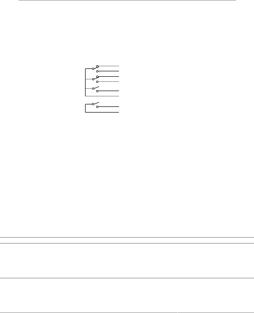
The ICM option board can be equipped with four relays. When equipped with four
relays, an 8–lead output cable (Reference Figure 1) is included. See the Metercat
Program Development Guide (TM42-2204B or later) for more information on configuring
relays for A3 ALPHA meters.
COMMO
N
Green
NO Brown
COMMO
N
Red
NO Orang
e
NO Blue
NC Wht/Blk
NO Black
NC Yellow
LC1
LC2
KYZ1
KYZ2
EOI
Load Control
RELAY A
RELAY B
RELAY C
RELAY D
A3 ALPHA
Programmable
Programmable
Programmable
Programmable
Y1
Z1
Y2
Z2
EOI
K
Figure 1