Electrolux 30 Induction Freestanding Range With Cooktop And Iq Touch Controls Ei30If40Ls Wiring Diagram 316904475_A_en
2015-03-28
: Electrolux Electrolux-30-Induction-Freestanding-Range-With-Induction-Cooktop-And-Iq-Touch-Controls-Ei30If40Ls-Wiring-Diagram-662480 electrolux-30-induction-freestanding-range-with-induction-cooktop-and-iq-touch-controls-ei30if40ls-wiring-diagram-662480 electrolux pdf
Open the PDF directly: View PDF ![]() .
.
Page Count: 4
316904475 Rev A (1305)
IMPORTANT
DO NOT REMOVE THIS BAG
OR DESTROY THE CONTENTS
WIRING DIAGRAMS AND SERVICE
INFORMATION ENCLOSED
REPLACE CONTENTS IN BAG
Electronic Surface Element Control (ESEC)
This range is equipped with an Electronic Surface Element
Control (ESEC), which precisely controls the smoothtop cooking
elements at multiple settings. For the user, the elements are
operated by pressing the touch pads located on the control panel
for the desired settings. The control settings are shown in 2-digit
displays.
Hot Surface display message - If any of the induction elements
are hot, the hot surface message (HE) will display and remain ON
until the cooktop cools.
ESEC lockout feature - The electronic oven control's self-
clean and Cooktop Lockout features will not operate when
a surface element is ON. Conversely, the surface elements
controlled by the ESEC will not operate when an oven control
self-clean or Cooktop Lockout mode is active. When the oven
control is in a self-clean or Cooktop Lockout mode, will appear
in the oven control display to signify that the surface heating
elements are locked out.
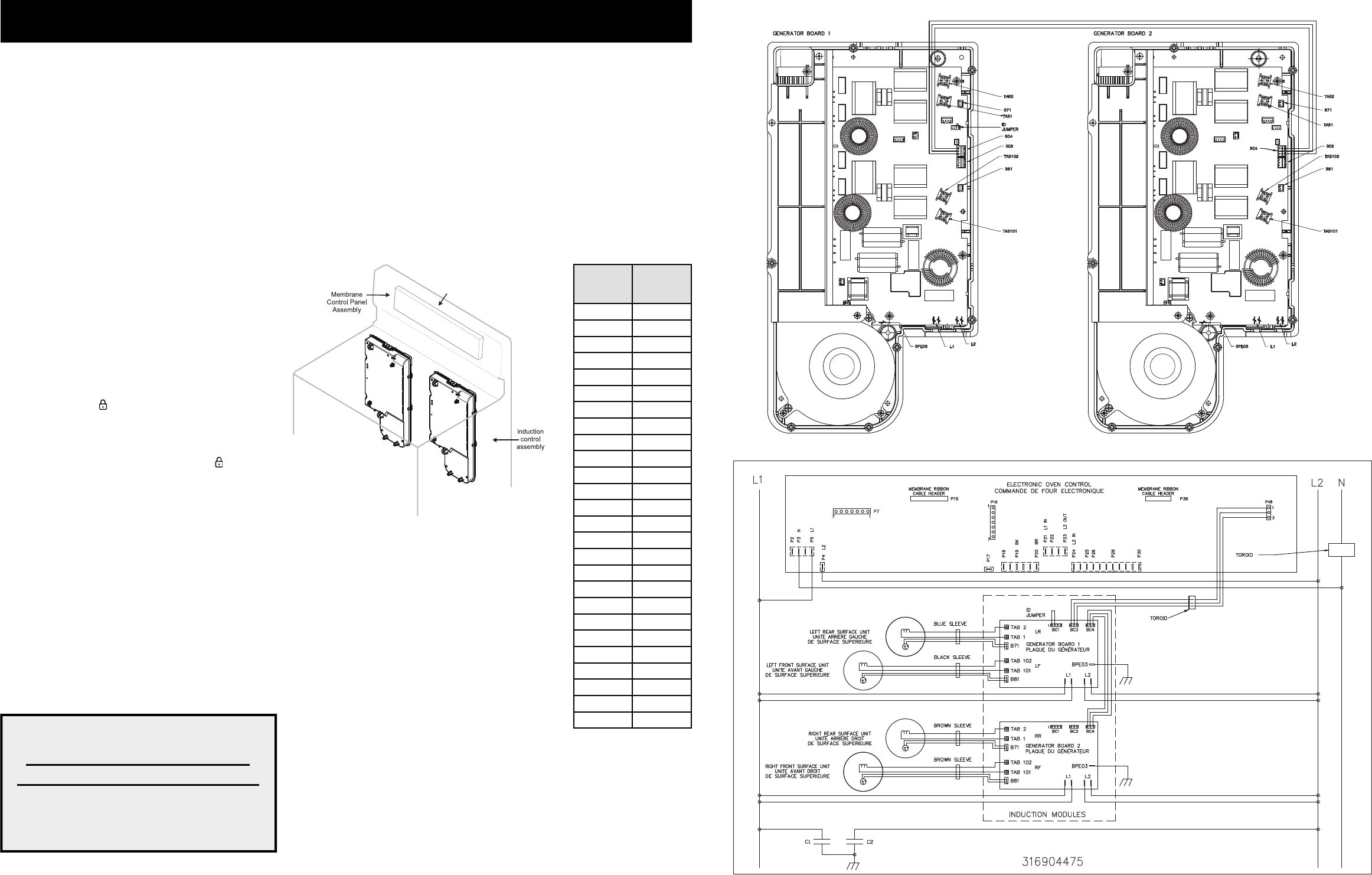
ESEC system components -
The ESEC system consists of the following components:
ES1040 oven/cooktop control (EOC) - circuit board mounted in
backguard.
Membrane control panel assembly - User interface that include
keypads and LEDs.
Induction control assembly - circuit boards in plastic housings
mounted on the range back side on two brackets with four screws.
SERVICE DATA SHEET
Electric Ranges with ES1040 and Induction Smooothop
electronic
oven/cooktop
control (EOC)
Notes on replacing parts
Replacing an induction control assembly – When
replacing an induction control assembly on the back of the
range, do not over-tighten the 2 screws that secure each
Control Assembly to the range or the screws that secure the
rear wire shield to the Control Assembly. Over-tightening the
screws can damage the plastic housings holding the circuit
boards.
Replacing an induction element
Whenever replacing any induction element use only the
screws supplied with the range to secure the element to the
mounting panel. Never use any other type of screw to attach
the induction element .
Replacing the membrane control panel assembly – The membrane control panel assembly
includes several parts and must be replaced as an assembly.
Replacing the ES1040 control* – When replacing the oven/cooktop control in the backguard,
DO NOT over tighten the screws that secure it. To secure the board use NO MORE THAN 20
in. - lbs. Over tightening these screws can possibly damage the board.
* Please note: Electronic boards are very sensitive to static electricity. Static electricity can
permanently damage electronic boards. Before handling these parts, be sure to drain static
electricity from your body by properly grounding yourself.
NOTICE - This service data sheet is intended for use by persons having electrical and mechanical training and a level of knowledge of these subjects
generally considered acceptable in the appliance repair trade. The manufacturer cannot be responsible, nor assume any liability for injury or damage of
any kind arising from the use of this data sheet.
SAFE SERVICING PRACTICES
To avoid the possibility of personal injury and/or property damage, it is important that safe servicing practices be observed. The following are examples, but without
limitation, of such practices.
1. Before servicing or moving an appliance remove power cord from electrical outlet, trip circuit breaker to OFF, or remove fuse.
2. Never interfere with the proper installation of any safety device.
3. GROUNDING: The standard color coding for safety ground wires is GREEN or GREEN WITH YELLOW STRIPES. Ground leads are not to be used as current
carrying conductors. It is extremely important that the service technician reestablish all safety grounds prior to completion of service. Failure to do so
will create a potential safety hazard.
4. Prior to returning the product to service, ensure that:
• All electric connections are correct and secure.
• All electrical leads are properly dressed and secured away from sharp edges, high-temperature components, and moving parts.
• All uninsulated electrical terminals, connectors, heaters, etc. are adequately spaced away from all metal parts and panels.
• All safety grounds (both internal and external) are correctly and securely reassembled.
Displayed
Power
Level
Power
Level %
Lo 3.0
1.2 3.5
1.4 4.0
1.6 4.5
1.8 5.0
2.0 5.5
2.2 6.0
2.4 7.0
2.6 8.0
2.8 9.0
3.0 10.5
3.5 13.0
4.0 15.5
4.5 18.0
5.0 21.0
5.5 25.0
6.0 31.0
6.5 38.0
7.0 45.0
7.5 50.0
8.0 54.0
8.5 59.0
9.0 64.0
9.5 80.0
Hi 100
Pb 125-141
SCHEMATIC DIAGRAM - Induction Controls Wiring/Connections
SCHEMATIC DIAGRAM - ESEC with Induction Cooktop
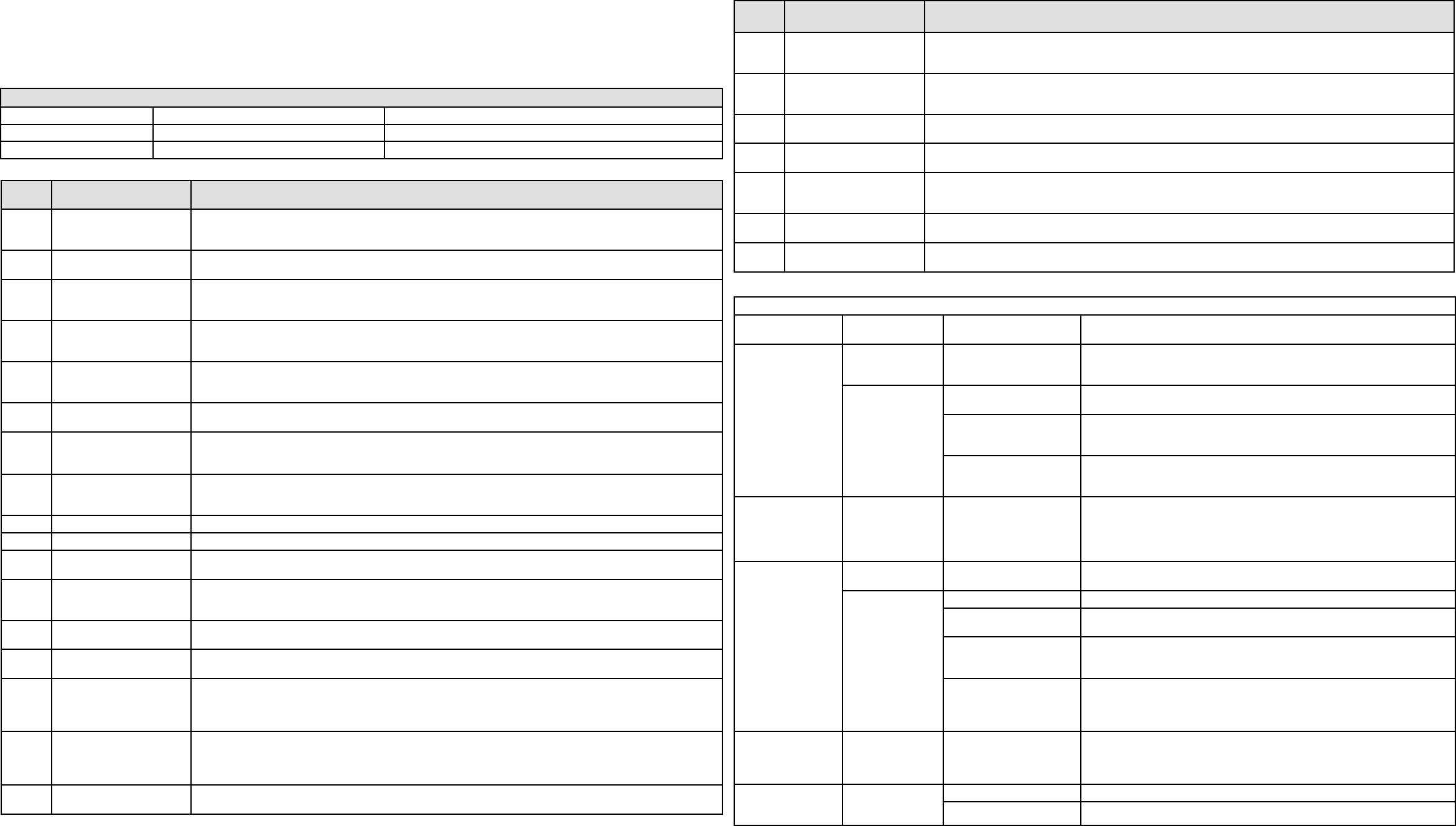
Electronic Surface Element Control System (ESEC) Error Code Descriptions
When a specifi c error condition occurs in the ESEC system a code will be displayed in the electronic control panel. The error codes are displayed as
“CO” in the left display followed by the code number in the right display. For each Error Code there is a listing of the likely cause or failure condition, as well as
suggested corrective actions to be taken. Always reset the power by disconnecting or turning off the power supply for 30 seconds to see if the failure condition will
clear. If the error code returns perform the steps one at a time in the order listed below to correct the specifi c failure condition. NOTE: If multiple changing error
codes are displayed check for disconnected wires or cables.
Tech Sheet Abbreviations and Terminology
EOC = Electronic Oven Control ESEC = Electronic Surface Element Control TST = Touch Sensor Technology (touch control glass panel)
UIB = User Interface Board TSEC = Touch Sensor Electronic Control RTD = Resistance Temperature Device. (Temp Probe or Temp Sensor)
VSC = Variable Speed Control PS = Power Supply board (PS1 , PS2, etc.) TCO = Thermal Cut Out also “Thermo Disc” or “Thermal Limiter”
Error
Code
Likely Cause or Failure
Condition
Suggested Corrective Action
11 Stuck key 1. Verify nothing is touching the membrane control panels. Disconnect Power, wait 30 seconds and repower. If fault
returns: 2.Check/reseat membrane tails between the membrane panel and EOC; 3. Replace EOC; 4. Replace mem-
brane panel.
14 Membrane panel connector
tail
1. Disconnect Power, wait 30 seconds and repower. If fault returns: 2.Check/reseat membrane tails between EOC and
the membrane panel; 3. Replace EOC; 4. Replace membrane control panel.
20/27 Communication failure be-
tween generator board and
EOC - left cooking zones
1. Verify communication harness between left and right side generator circuit board is not damaged and is properly in-
stalled; 2. Verify AC power harness is not damaged and is properly installed; 3. Verify ID1 jumper is properly installed;
4. Replace the EOC; 5. Replace the left side generator board.
21/28 Communication failure be-
tween generator board and
EOC - right cooking zones
1. Verify communication harness between left and right side generator circuit board is not damaged and is properly in-
stalled; 2. Verify AC power harness is not damaged and is properly installed; 3. Verify ID1 jumper is properly installed;
4. Replace the EOC; 5. Replace the right side generator board.
23 Communication failure be-
tween both generator boards
and EOC
1. Verify AC power supply to the appliance is 240V; 2. Verify communication harness between the EOC and the left
side generator board is not damaged and is properly installed; 3. Replace the EOC; 4. Replace both communication
harnesses; 5. Replace the left side generator board.
30, 35 AC input too high
AC input too low
1. Verify AC power supply to the appliance is 240V; 2. Verify cables and connections on the left side generator circuit
board are not damaged and are properly installed; 3. Replace the left side generator circuit board.
31, 32,
34, 36,
37, 40
Internal generator error 1. Verify cables and connections on the left side of the generator circuit board are not damaged and are properly
installed; 2. Replace the left side generator circuit board.
33 Cooling fan blocked 1. Verify cables and connections on the left side generator circuit board are not damaged and are properly installed;
2. Verify there is nothing touching or interfering with the fan on the left side generator circuit board; 3. Replace the left
side generator circuit board.
38 Cooling fan not connected 1. Verify fan is properly connected; 2. Replace the left side generator circuit board.
39 Confi guration error 1. Replace the EOC; 2. Replace both generator circuit boards.
41 Induction sensor (coils)
defect
1. Verify if the left side inductor (coils) are connected properly (measure approx. 0 Ohm); 2. Replace left side genera-
tor circuit board if 0 Ohm, otherwise replace the inductor (coil).
42, 43 General pot detection
Pot detection sensor failure
1. Verify pans are the proper material (magnet sticks to bottom of pan); 2. Verify pan is in the proper condition (not
warped, rusty); 3. Verify the pan is the proper size and placed correctly on the cooking zone. 4. Replace left side
generator circuit board.
44 Generator circuit board tem-
perature warning
1. Ensure cooktop is not being used with a dry pan at a high temperature setting; 2. Verify that installation follows the
installation instructions, check ventilation; 3. Allow zone to cool before continuing to cook.
45 Generator circuit board tem-
perature alarm
1. Ensure cooktop is not being used with a dry pan at a high temperature setting; 2. Verify that installation follows the
installation instructions, check ventilation; 3. Replace left side generator circuit board.
51
52
55
56
LF temp sensor failure
LR temp sensor failure
RF temp sensor failure
RR temp sensor failure
1. Verify induction temperature sensor is properly connected (see wiring diagram); 2. Verify the inductor temperature
sensor is properly installed and not damaged (measure approx. 100K Ohm at room temperature); 3. Replace applica-
ble generator circuit board, left or right (see wiring diagram).
63
64
67
68
LF temp sensor too hot
LR temp sensor too hot
RF temp sensor too hot
RR temp sensor too hot
1. Ensure cooktop is not being used with a dry pan at a high temperature setting; 2. Verify the inductor temperature
sensor is properly installed and not damaged (measure approx. 100K Ohm at room temperature); 3. Replace applica-
ble generator circuit board, left or right (see wiring diagram).
70
75
AC input too high
AC input too low
1. Verify AC power supply to the appliance is 240V; 2. Verify cables and connections on right side generator circuit
board are not damaged and are properly installed; 3. Replace the right side generator circuit board.
Error
Code
Likely Cause or Failure
Condition
Suggested Corrective Action
71, 72,
74, 76,
77, 80
Internal generator error 1. Verify cables and connections on the right side generator circuit board are not damaged and are properly installed;
2. Replace the right side generator circuit board.
73 Cooling fan blocked 1. Verify cables and connections on the right side generator circuit board are not damaged and are properly installed;
2. Verify there is nothing touching or interfering with the fan on the right side generator circuit board; 3. Replace the
right side generator circuit board.
78 Cooling fan not connected 1. Verify fan is properly connected; 2. Replace the right side generator circuit board.
81 Induction sensor (coils)
defect
1. Verify if the right side inductor (coils) are connected properly (measure approx. 0 Ohm); 2. Replace right side generator
circuit board if 0 Ohm, otherwise replace the inductor (coil).
82
83
General pot detection
Pot detection sensor failure
1. Verify pans are the proper material (magnet sticks to bottom of pan); 2. Verify pan is in the proper condition (not
warped, rusty); 3. Verify the pan is the proper size and placed correctly on the cooking zone. 4. Replace right side
generator circuit board.
84 Generator circuit board tem-
perature warning
1. Ensure cooktop is not being used with a dry pan at a high temperature setting; 2. Verify installation follows the
installation instructions, check ventilation; 3. Allow zone to cool before continuing to cook.
85 Generator circuit board tem-
perature alarm
1. Ensure cooktop is not being used with a dry pan at a high temperature setting; 2. Verify installation follows the
installation instructions, check ventilation; 3. Replace right side generator circuit board.
Additional Failure Conditions
Symptom or Failure Control Display Possible Cause or Con-
dition
Suggested Corrective Action
Pan does not heat up. Normal operation Pan too small for proper pan
detection and only works
with low power.
Use larger pan or this pan on a smaller cooking zone. Refer to owners guide for
proper pan selection.
Flashing power
level Display and
pan does not heat.
Pan not detected. Check whether the pots or pans are suitable for induction. Refer to owners guide
for proper pan selection.
Induction surface unit not
correctly connected or
surface unit open.
Check the surface unit wire terminal connections. Ensure that they are properly
connected and tightened. Test continuity of element (should be less than 1 ohm).
Distance between surface
unit and glass ceramic too
large.
Check whether the surface unit is properly positioned and touching the glass cooktop
surface.
Individual buttons
cannot be used or
cannot always be
used.
None 1. Test cables and
connections.
2. Membrane control
panel defective.
3. EOC defective.
1. Follow instructions for proper use of controls.
2. Verify membrane tail connections between EOC and membrane panel. Replace
if defective or damaged.
3. Replace membrane control panel assembly.
4. Replace EOC.
Cooking power too
low or shuts down
prematurely.
None Fluids spilled or object lying
on control panel keypads.
Clean up spills or remove objects. Restart cooktop in normal manner.
Normal Operation Ventilation slots obstructed. Clear vent openings.
Unsuitable pots (bottom
bent).
Follow owner's guide for proper pan selection.
Distance between surface
unit and glass ceramic too
large.
Check whether the surface unit is properly positioned and touching the glass cooktop
surface.
Fan does not start. 1. With two cook zones operating, verify that the fan runs at a slow speed. If
fans do not run, check for foreign objects or stuck fan motor.
2. Test continuity of motor windings. Replace motor if open.
3. Replace induction control assembly.
Steady "HE" in
display when cooking
zone is cold and
switched off.
"HE" Temperature sensor defect. 1. Test surface unit RTD approx. 1K ohms at room temperature. Replace surface
unit if resistance is not correct.
2. Replace induction control assembly.
Cooktop does not
initialize/operate.
Blank
No display
No beep
EOC not powered. Verify installation and harness connections to EOC.
Defective EOC. Replace EOC.
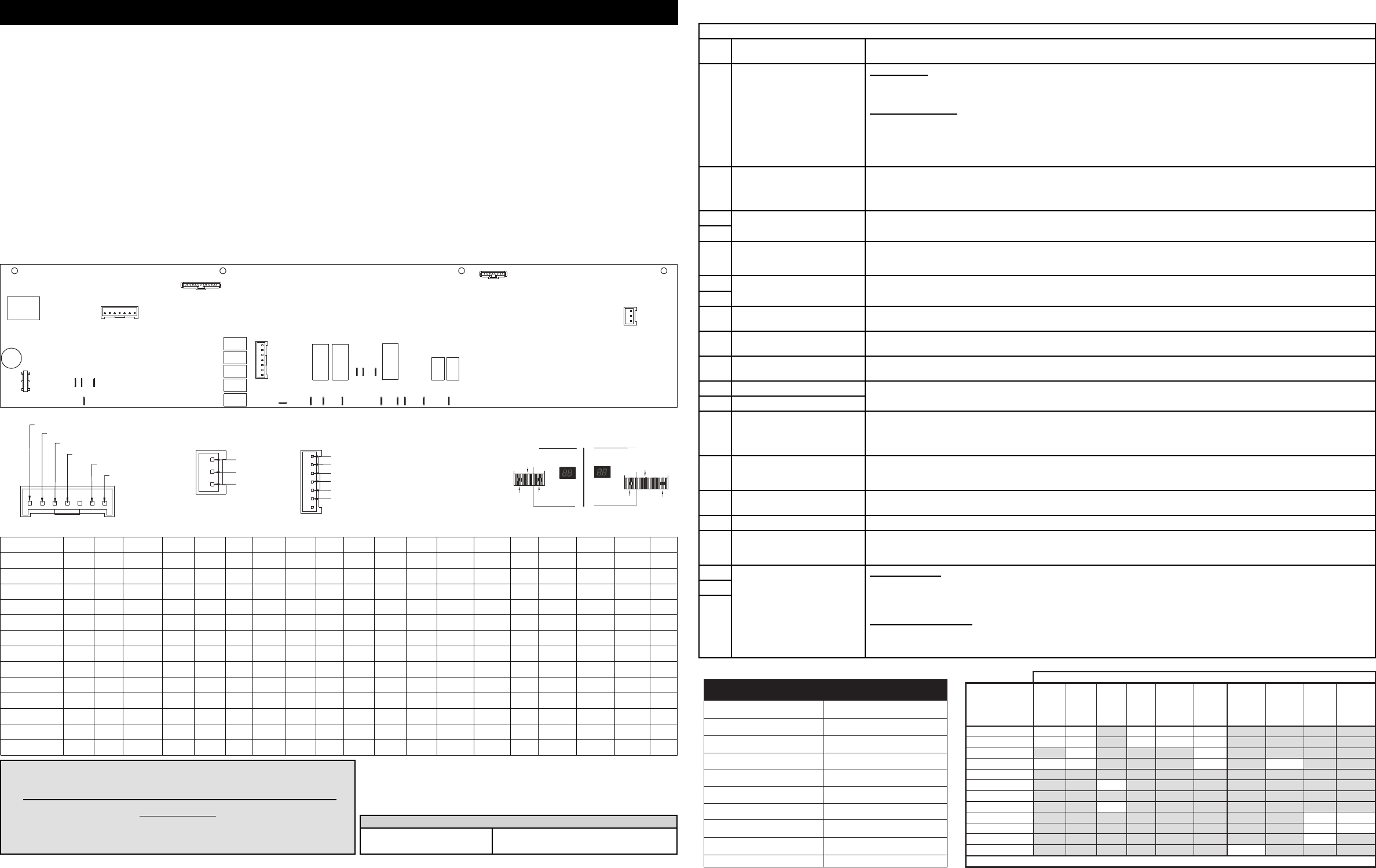
P5P2 P3
P4
P7
K10
K11
K12
K13
P17 P18 P19 P20
K18
K17
P21
P22
P23
K19
P24 P25 P26 P28 P30
K22
K23
P36
1
1
P15
1
P16
1
MEMBRANE KEY MEMBRANE LED
P3 - N
P4 - L2
P5 - L1
P17 - L1 IN
P19 - BAKE
P20 - BROIL
P21 - L1 IN
P23 - L2 OUT
P24 - L2 IN
P28 - L2 IN
P30 - WZ
P7
PIN 1-OVEN PROBE
PIN 2-OVEN PROBE
PIN 4-COMMON
PIN 5-DOOR SWITCH
PIN 6-LOCK SWITCH P48
PIN 1-+5V
PIN 3-GND
PIN 2-TX/RX
P16
1PIN 1-MDL
PIN 3-FAN MOTOR
PIN 2-CATALYST/CLEAN
PIN 4-CONV ELEMENT
PIN 6-OVEN LAMP
P15
20 PIN
RIBBON TAIL
PIN 1 PIN 20
P36
12 PIN
RIBBON TAIL
PIN 12PIN 1
RIBBON CONNECTIONS
(ELECTRIC MODELS ONLY)
LEFT SIDE RIGHT SIDE
VIEW FROM FRONT OF DISPLAY
K14
1
P48
PIN 5-WD ELEMENT
1
PIN 7-WD TOD
NOTICE - This service data sheet is intended for use by persons having electrical and
mechanical training and a level of knowledge of these subjects generally considered
acceptable in the appliance repair trade. The manufacturer cannot be responsible, nor
assume any liability for injury or damage of any kind arising from the use of this data
sheet.
Safe servicing practices
To avoid the possibility of personal injury and/or property damage, it is important that safe
servicing practices be observed. The following are examples, but without limitation, of such
practices.
1. Before servicing or moving an appliance, remove power cord from electrical outlet, trip
circuit breaker to OFF, or remove fuse.
2. Never interfere with the proper installation of any safety device.
3. GROUNDING: The standard color coding for safety ground wires is GREEN or GREEN
WITH YELLOW STRIPES. Ground leads are not to be used as current carrying
conductors. It is extremely important that the service technician reestablish all
safety grounds prior to completion of service. Failure to do so will create a
potential safety hazard.
4. Prior to returning the product to service, ensure that:
• All electric connections are correct and secure.
• All electrical leads are properly dressed and secured away from sharp edges, high-
temperature components, and moving parts.
• All uninsulated electrical terminals, connectors, heaters, etc. are adequately spaced
SERVICE DATA SHEET - Electric Range with ES 1040 Electronic Oven Control
PN 316904476 Rev A (1305)
away from all metal parts and panels.
• All safety grounds (both internal and external) are correctly and securely
reassembled.
Oven Calibration
Set the electronic oven control for normal baking at 350°F. Obtain an average oven
temperature after a minimum of 5 cycles. Press cancel key to end bake mode.
Temperature Adjustment
1. While in a non-cooking mode, press and hold the bake key for 6 seconds.
2. The current calibration offset (temperature adjustment) should appear in the
temperature display.
3. Use the number keypad (0-9) to enter the desired amount of adjustment (up to
35°F).
4. Press the bake key to change the sign of the adjustment to a (-) if necessary. A
positive adjustment will not display a sign.
5. Once the desired adjustment (-35° to 35° F) has been entered, press the start key
to accept the change or the cancel key to reject the change.
NOTE: Changing calibration affects all baking modes. The adjustments made will not
change the self-cleaning temperature.
CONNECTOR-PIN # P15-1 P15-2 P15-3 P15-4 P15-5 P15-6 P15-8 P15-9 P15-10 P15-18 P15-19
P15-7 CONNECT
LOOP
P15-11 1 BAKE CONV
CONVERT
COOK
TIME
CONTROL
LOCK 9WZ
ON/OFF
P15-12 4 BROIL MY
FAVORITES
END
TIME
COOKTOP
LOCK 6WZ
SELECT
P15-13 7SLOW
COOK
CONV
ROAST
SET
CLOCK
OVEN
LIGHT 3LF
SIZE
P15-14 START CONV
BAKE
KEEP
WARM
TIMER
ON/OFF 02 RR
SIZE
P15-15 CANCEL CONV
BROIL
RAPID
PREHEAT
SELF
CLEAN 85
CONNECT
LOOP
RF
SIZE
P15-16 LF
ON/OFF
LF
LOW
LF
MED
LF
HIGH
LR
ON/OFF
LR
LOW
LR
MED
LR
HIGH
CONNECT
LOOP
P15-17 RF
ON/OFF
RF
LOW
RF
MED
RF
HIGH
RR
ON/OFF
RR
LOW
RR
MED
RR
HIGH
CONNECT
LOOP
P15-20 CONNECT
LOOP
WZ ON
(BOTTOM)
WZ_LOW
(LOWEST)
WZ
MED LOW
LF1 SIZE
(BOTTOM)
LF2 SIZE
(TOP)
RR1 SIZE
(BOTTOM)
WZ MED WZ
MED HIGH
WZ HIGH
(HIGHEST)
RR2 SIZE
(TOP)
RF1 SIZE
(BOTTOM)
RF2 SIZE
(TOP)
CONNECT
LOOP
P36-9
P36-10
P36-11
(UNUSED)
P36-12
P36-1 P36-2 P36-3 P36-4 P36-5 P36-6 P36-7 P36-8
-
-
-
-
-
-
-
------
-
-
-
-
-
-
-
-------
-
-
-
-
-
-
-
-
-
-- -
-
-
-
-
-
-
-
-
-
-
-
-
-
-
-
-
-
-
-
-
-
-
-
-
-
-
-----
-
-
-
-
-
-
-
-
-
-
-
-
-
-
-
-
-
-
-
-
-
-
-
-
-
-
-
-
-
-
-
-
-
-
-
-
-
-
-
-
-
-
-
-
-
-
-
-
-
-
-
--
-
-
-
-
-
-
-
-
-
-
-
-
-
-
-
-
-
-
-
-
-
-
-
-
-
-
-
-
-
-
-
-
-
-
-
-
-
-
-
-
-
-
-
-
-
-
-
-
WD
ON/OFF
WD
SELECT
WD ON
BOTTOM
WD LOW
LOWEST
WD MED
WD
HIGH
Tech Sheet Abbreviations and Terminology
EOC = Electronic Oven Control
VSC = Variable Speed Control
PS = Power Supply board (PS1, PS2, etc.)
RTD = Resistance temperature device (Temp. probe/sensor)
TCO = Thermal cut out, also "thermo disc" or "thermal limiter"
PS = Power Supply board (PS1, PS2, etc.)
Resistance (ohms)
1000 ± 4.0
1091 ± 5.3
1453 ± 8.9
1654 ± 10.8
1852 ± 13.5
2047 ± 15.8
2237 ± 18.5
2697 ± 24.4
Open circuit/infinite resistance
RTD SCALE
Temperature °F (°C)
32 ± 1.9 (0 ± 1.0)
75 ± 2.5 (24 ± 1.3)
250 ± 4.4 (121 ± 2.4)
350 ± 5.4 (177 ± 3.0)
450 ± 6.9 (232 ± 3.8)
550 ± 8.2 (288 ± 4.5)
650 ± 9.6 (343 ± 5.3)
900 ± 13.6 (482 ±7.5)
Probe circuit to case ground
IMPORTANT
DO NOT REMOVE THIS BAG OR DESTROY THE
CONTENTS
WIRING DIAGRAMS AND SERVICE INFORMATION ENCLOSED
REPLACE CONTENTS IN BAG
To test keypad function, check for continuity between indicated pin locations while
pressing the keypad. EXAMPLE: test the BAKE key on connector P15 with the P2 and
P11; test the Warmer Zone Medium on connector P36 with P1 and P10.
L1 to
Bake
L1 to
Broil
L1 to
Motor
Door
Latch
L1 to
Conv
Bake
Fan
L1 to
Conv.
Heang
Element
L2 In to
L2 Out
L1 to
Warming
Drawer
L1 to
Catalyst
Element
L1 to
Oven
Lamps
Door
Switch
Contacts
COM-NO
Bake/Time Bake X◊X* X† X† X
Conv Bake X◊ X* X X X
XXli
orB
Clean X◊ XX*X
Unlocked
XgnikcoL
Locked
XgnikcolnU
Door Open XO
Door Closed OX
Oven Lamps ON X
Warming Drawer X◊
EOC Relays - ES1030 Oven Control (Electric)
NOTE: X=Circuit Contacts Closed O = Circuit Contacts Open * = Alternates with Bake Element † = During Preheat ◊ = Cycles as Needed
Electronic Oven Control Fault Code Descriptions
Fault
Code
Likely failure condition/cause Suggested corrective action
F10 Runaway temperature.
Oven heats when no cook cycle is
programmed.
If Oven is cold:
1. If fault code is present with cold oven, test oven temperature sensor probe circuit resistance. Use RTD scale found in the tech sheet.
2. Replace probe or repair wiring connections if defective.
3. If temperature sensor probe circuit is good but fault code remains when oven is cold replace the EOC.
If Oven is overheating:
1. If oven is severely overheating/heating when no cook cycle is programmed, test oven temperature sensor probe circuit resistance
using the RTD scale found in the service tech sheet. Also verify that the temperature sensor probe in properly installed in the oven
cavity.
2. Disconnect power from the range, wait 30 seconds and reapply power. If oven continues to heat when the power is reapplied, replace
the EOC. NOTE: Severe overheating may require the entire oven to be replaced should damage be extensive.
F11 Shorted keypad or selector switch. 1. Reset power supply to range - Disconnect power, wait 30 seconds and reapply power.
2. Check/reseat ribbon harness connections between touch panel and EOC.
3. Test keyboard circuits using test matrix. Replace touch panel if defective.
4. If keyboard circuits check correctly, replace the EOC.
F12 EOC Internal software error or
failure.
Disconnect power, wait 30 seconds and reapply power. If fault returns upon power-up, replace EOC.
F13
F14 Keyboard tail failure. 1. Check/reseat ribbon harness connections between keyboard touch panel and EOC.
2. Test keyboard circuits using test matrix (below). Replace touch panel if defective.
3. If keyboard circuits check correctly, replace EOC.
F17 EOC Internal hardware error of
failure.
Disconnect power, wait 30 seconds and reapply power. If fault returns upon power-up, replace EOC.
F18
F30 Open oven sensor probe circuit. Check resistance at room temperature and compare to RTD Sensor resistance chart. If resistance is correct replace the EOC. If resistance
does not match the RTD chart, replace RTD sensor probe. Check sensor wiring harness between EOC and sensor probe connector.
F31 Shorted oven sensor probe circuit. Check resistance at room temperature. If less than 500 ohms, replace RTD sensor probe. Check for shorted sensor probe harness between
EOC and probe connector. If resistance is correct, replace the EOC.
F42 EOC internal software
confi guration error.
Usually this failure code would only appear if the EOC has been replaced with an incorrect version. Verify that the correct replacement part
number is being used.
F50 Internal signal voltage error. Disconnect power, wait 30 seconds and reapply power. If fault returns when power is reapplied, replace EOC.
F51 Display communication error.
F60 EOC oven temperature. Higher
than normal temperature detected
on the EOC board.
1. Verify proper assembly of backguard panel. Check for damaged or loose panels, brackets, endcaps, etc.
2. Check for blocked ventilation slots in control panel rear cover.
3. Inspect oven vent for proper assembly and air fl ow.
4. Verify operation of cooling fan (if present).
F64 Time Base failure. The EOC
cannot determine if connected to
50Hz or 60Hz power supply.
Confi rm that range is connected to proper power source (50Hz or 60Hz). Generators or other portable power supplies and solar grids, etc.,
may not provide proper power supply. If power source is correct, replace the EOC.
F65 Keyboard short circuit or internal
EOC failure.
1. Test keyboard circuits using test matrix. Replace touch panel if defective.
2. If keyboard circuits check correctly, replace the EOC
F66 EOC internal power supply failure. Disconnect power, wait 30 seconds and reapply power. If fault returns upon power-up, replace EOC.
F68 High voltage condition. L1 or L2
may be crossed with Neutral on
incoming PS.
1. Verify proper incoming line voltage and polarity of L1, L2 and Neutral power supply connections at range terminal block.
2. If power supply voltage and polarity are correct, replace EOC.
F90 Door lock motor or latch circuit
failure.
If lock motor runs:
1. Test continuity of wiring between EOC and lock switch on lock motor assy. Repair if needed.
2. Advance motor until cam depresses the plunger on lock motor switch. Test continuity of switch contacts. If switch is open replace lock
motor assembly.
3. If motor runs and switch contacts and wiring harness test correctly, replace the EOC.
If lock motor does not run:
1. Test continuity of lock motor windings. Replace lock motor assembly if windings are open.
2. Test lock motor operation by using a test cord to apply voltage. If motor does not operate, replace lock motor assy.
3. If motor runs with test cord, check continuity of wire harness to lock motor terminals. If harness is good replace the EOC.
F91
F95
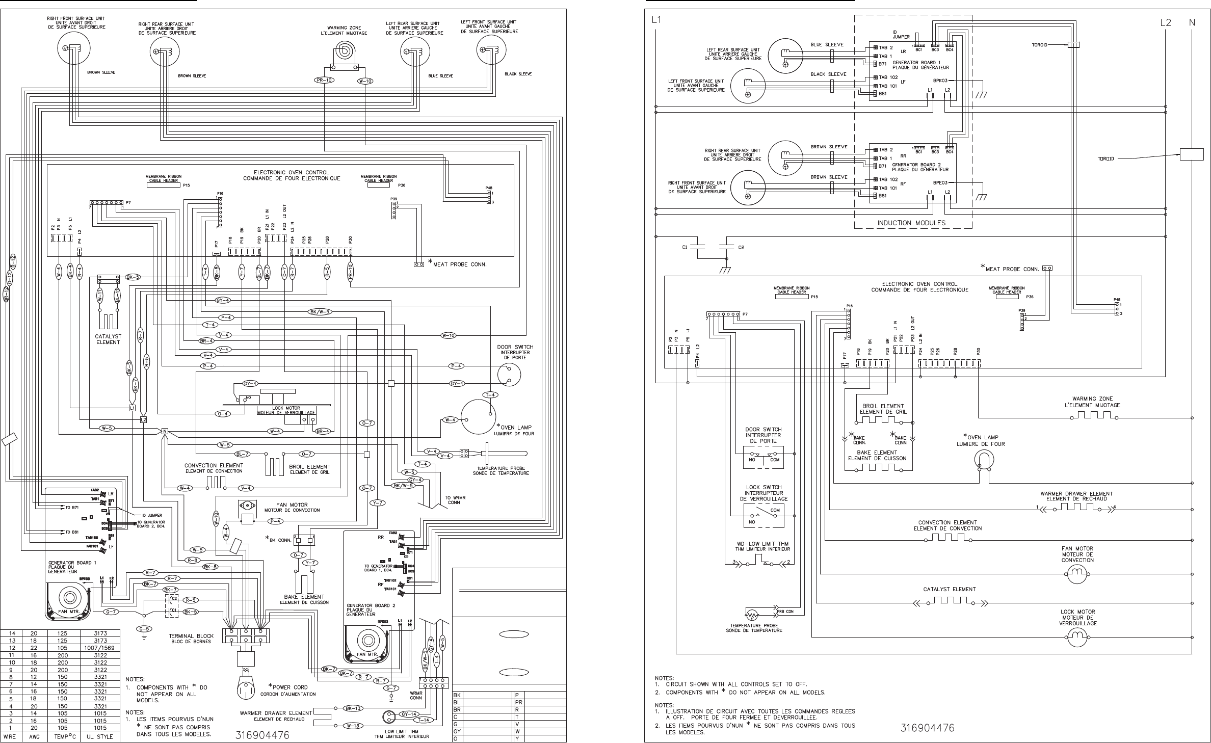
General Troubleshooting Diagram General Troubleshooting Schematic
AVERTISSEMENT
EXAMPLE:
FIRST, STRIPE NEXT.
COPPER / CUIVRE
GREEN / VERT
BROWN / BRUN
BLACK / NOIR
ORANGE
GRAY / GRIS
BLUE / BLEU
EXEMPLE:
FIL VERT AVEC BANDE JAUNE.
COLOR CODE / CODE DES COULEURS
CELLE DE TOUTE BANDE.
DU FIL EN PREMIER. SUIVIE DE
LEGENDE DE FILAGE: LA COULEUR
GREEN WIRE WITH YELLOW STRIPE.
L' ALIMENTATION ELECTRIQUE AVANT
TRACER WIRE: WIRE COLOR NOTED
DE FAIRE TOUT SERVICE D' ENTRETIEN
DEBRANCHEZ L' APPAREL DE
DISCONNECT POWER BEFORE SERVICING
G / Y-8
VIOLET
RED / ROUGE
WHITE / BLANC
YELLOW / JAUNE
TAN / BRUN CLAIR
PURPLE / POURPRC
PINK / ROSE
G / Y-8
WARNING
