Electrolux Dishwasher 7 05 Compact Users Manual 595667700_all
7.05 Compact to the manual cfe6c4b1-5ff7-4981-9d0b-37a1c87d0ca3
2015-01-16
: Electrolux Electrolux-Electrolux-Dishwasher-7-05-Compact-Users-Manual-246746 electrolux-electrolux-dishwasher-7-05-compact-users-manual-246746 electrolux pdf
Open the PDF directly: View PDF ![]() .
.
Page Count: 30
- A FUNCTION KEYS
- A1 DISPLAY OF AUXILIARY VALUES
- A2 ACCESSING THE USER MENU
- A2.1 EXIT
- A3 SERVICE MENU
- A3.1 PARAMETERS
- A3.1.1 GENERIC FUNC. ( GFu)
- A3.1.2 RINSE MODULE (rin)
- A3.1.3 WASH MODULE (tub)
- A3.1.4 PREWASH MODULE (PrE)
- A3.1.5 COMMUNICATION (COM)
- A3.1.6 APEX PARAMETERS
- A3.2 INFO
- A3.3 RINSE CONTROL
- A4 ACCESSING DATA ON THE CHEMISTRY USED IN THE MACHINE
- B CONNECTORS LAYOUT
- B1 CONNECTORS LAYOUT LEGEND
- C INVERTER PARAMETERS
- C1 INVERTER PROGRAMMING
- C1.1 DISPLAY FUNCTIONS
- C1.2 INVERTER CONTROL TERMINAL ELECTRICAL CONNECTIONS
- C1.3 PARAMETRI DI CONFIGURAZIONE
- D WARNING MESSAGES AND TROUBLESHOOTING
- E LACK OF DETERGENT AND RINSE AID WARNINGS
DOC. NO. 5956.677.00 P. 1 / 30
Electrolux
EFS - Dishwashing Systems Platform
Electrolux Professional
SERVICE MANUAL
COMPACT ECOLAB USA
RACK-TYPE DISHWASHERS
CONTENTS: This document contains all the parameters and information for programming the electronic boards.
EDITION: 07.2009
Valid for firmware versions:
• 7.05 COMPACT ECOLAB USA.
WARNING:
All the safety regulations and procedures to be followed by the Specialised Technician/Technical Assist-
ance performing electrical, mechanical or electronic maintenance operations are contained in the instruc-
tion manual supplied with the machine: refer to this document before operating. This applies for anyone
carrying out operations using these documents. The specialised technician must wear personal protec-
tion equipment suitable for the work being performed (e.g. gloves, safety glasses and shoes, suitable
clothing, etc.) and use appropriate tools, equipment and auxiliary means.

DOC. NO. 5956.677.00 P. 2 / 30
Electrolux
EFS - Dishwashing Systems Platform
Electrolux Professional
INDEX
A FUNCTION KEYS............................................................................................. Pag. 4
A1 DISPLAY OF AUXILIARY VALUES................................................................................. Pag. 4
A2 ACCESSING THE USER MENU..................................................................................... Pag. 5
A2.1 EXIT .................................................................................................................... Pag.6
A3 SERVICE MENU ............................................................................................................. Pag. 7
A3.1 PARAMETERS.................................................................................................... Pag. 8
A3.1.1 GENERIC FUNC. ( GFu) ..................................................................Pag. 8
A3.1.2 RINSE MODULE (rin) ....................................................................... Pag. 12
A3.1.3 WASH MODULE (tub)....................................................................... Pag. 12
A3.1.4 PREWASH MODULE (PrE) .............................................................. Pag. 12
A3.1.5 COMMUNICATION (COM) ............................................................... Pag. 13
A3.1.6 APEX PARAMETERS....................................................................... Pag. 13
A3.1.6.1 Start-up menu (SUP) .................................................... Pag. 14
A3.1.6.2 Adjustment menu (probe) (AdJ) ................................... Pag. 14
A3.1.6.3 Adjustment menu (time) (AdJ)......................................Pag. 15
A3.1.6.4 Setup menu (SEt) .........................................................Pag. 16
A3.1.6.5 Test menu (tSM) ........................................................... Pag. 16
A3.2 INFO.................................................................................................................... Pag.18
A3.3 RINSE CONTROL............................................................................................... Pag. 18
A4 ACCESSING DATA ON THE CHEMISTRY USED IN THE MACHINE ........................... Pag. 19
B CONNECTORS LAYOUT ................................................................................. Pag. 21
B1 CONNECTORS LAYOUT LEGEND ................................................................................Pag. 23
C INVERTER PARAMETERS.............................................................................. Pag. 24
C1 INVERTER PROGRAMMING ......................................................................................... Pag. 24
C1.1 DISPLAY FUNCTIONS........................................................................................ Pag. 24
C1.2 INVERTER CONTROL TERMINAL ELECTRICAL CONNECTIONS..................Pag. 24
C1.3 PARAMETRI DI CONFIGURAZIONE.................................................................. Pag. 25
D WARNING MESSAGES AND TROUBLESHOOTING..................................... Pag. 26
E LACK OF DETERGENT AND RINSE AID WARNINGS .................................. Pag. 30

DOC. NO. 5956.677.00 P. 3 / 30
Electrolux
EFS - Dishwashing Systems Platform
Electrolux Professional
INDEX OF FIGURES AND TABLES
Figure 1 Menu access keys.............................................................................................................. Pag.4
Figure 2 Accessing current, water volumes and levels display mode.............................................. Pag.4
Figure 3 Accessing the USER MENU ..............................................................................................Pag.6
Figure 5 Accessing the SERVICE MENU ........................................................................................ Pag.7
Figure 6 Parameter and function access menu chart....................................................................... Pag.8
Figure 7 Accessing the APEX INFORMATIONS.............................................................................. Pag.19
Figure 8 Inverter electrical connection ............................................................................................. Pag.24
Table 1: Drain cycle: Cleaning mode (ClM) = 0 ...............................................................................Pag.9
Table 2: Drain and "sanitisation" hot cleaning cycle: Cleaning mode (ClM) = 1 à default ...............Pag.10
Table 3: Drain and cold cleaning cycle: Cleaning mode (ClM) = 2 .................................................. Pag.11
Table 4: Default Set Points .............................................................................................................. Pag.17
Table 5: Estimated Rinse Volume.................................................................................................... Pag.17
Electrolux
EFS - Dishwashing Systems Platform
Electrolux Professional
DOC. NO. 5956.677.00 P. 4 / 30
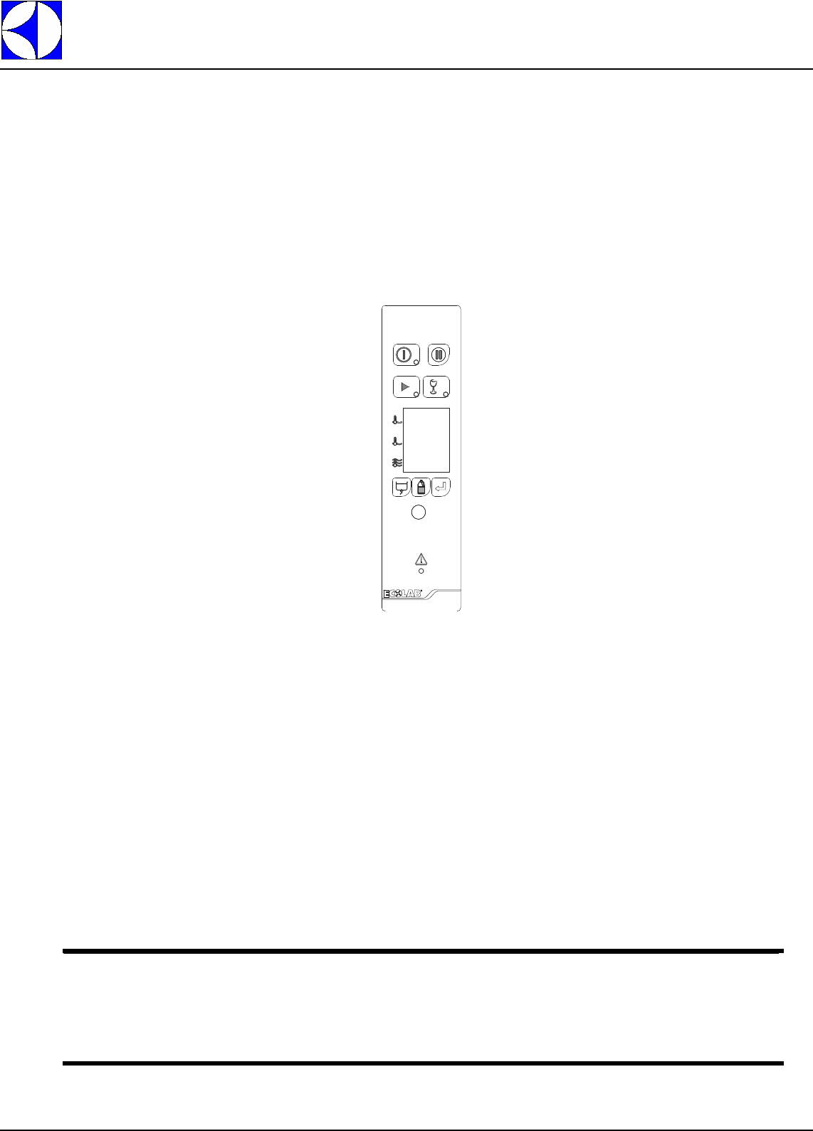
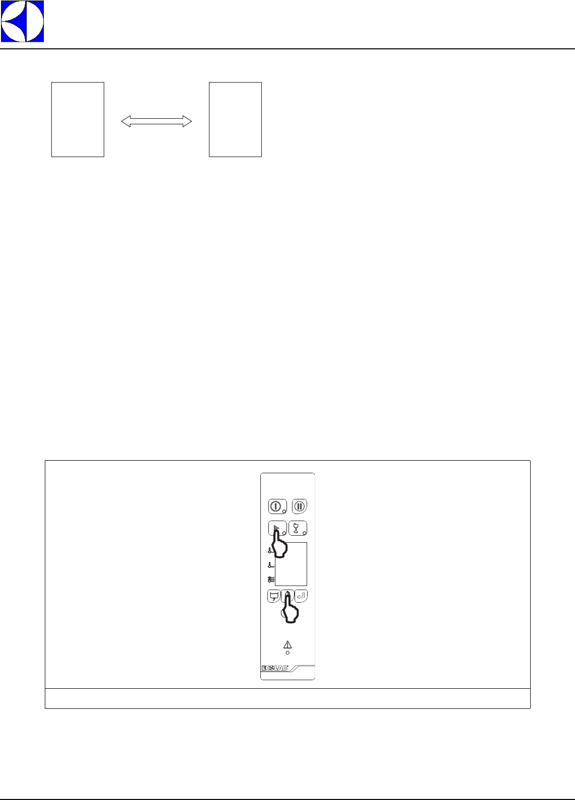
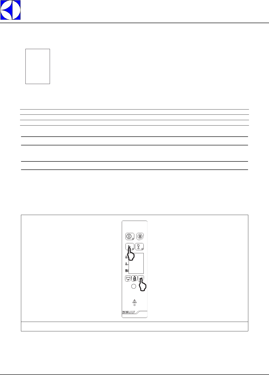
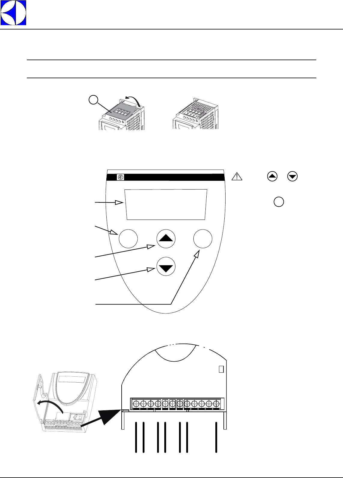
A FUNCTION KEYS
BUTTONS USED
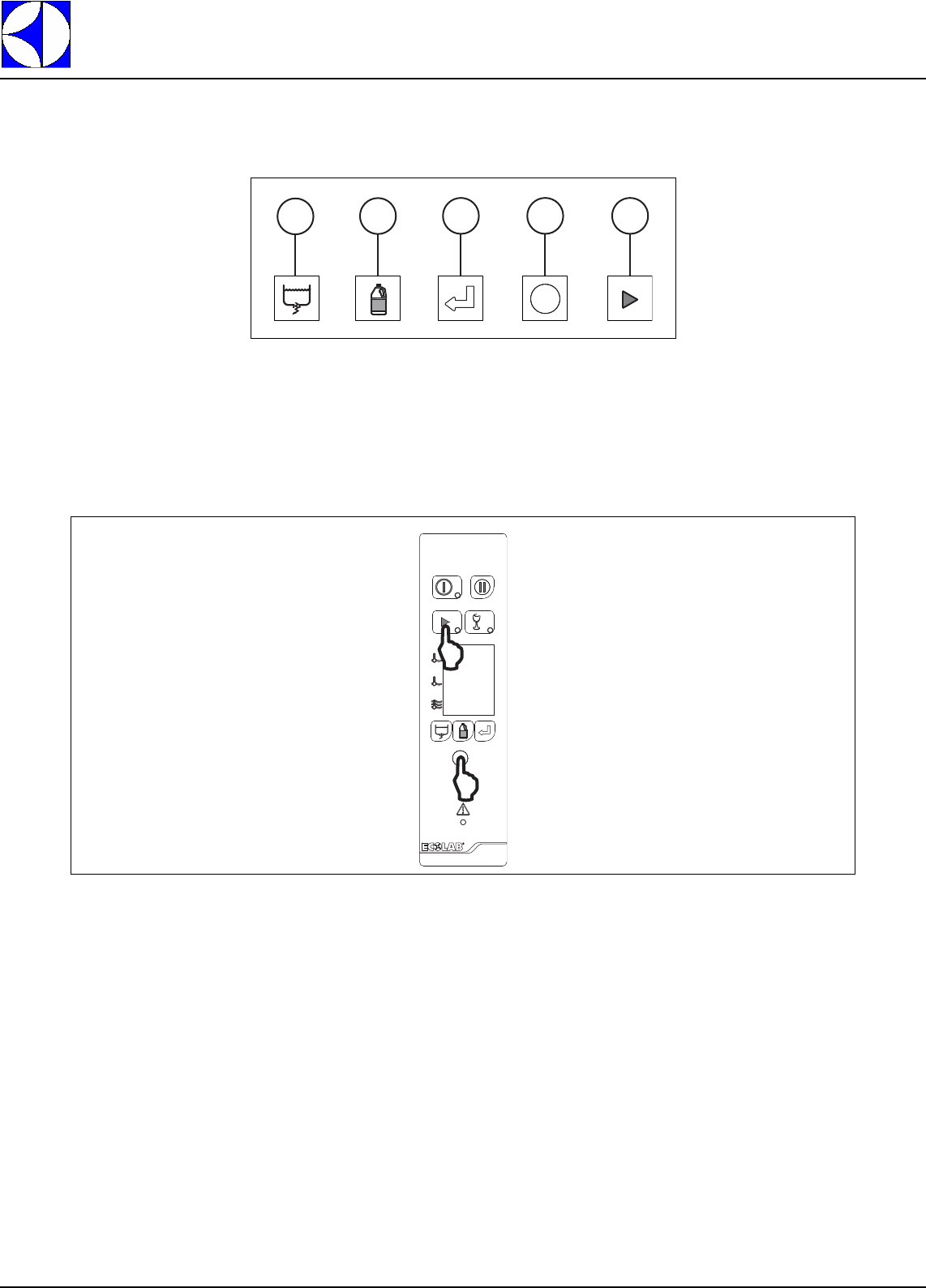
Figure 1
Menu access keys
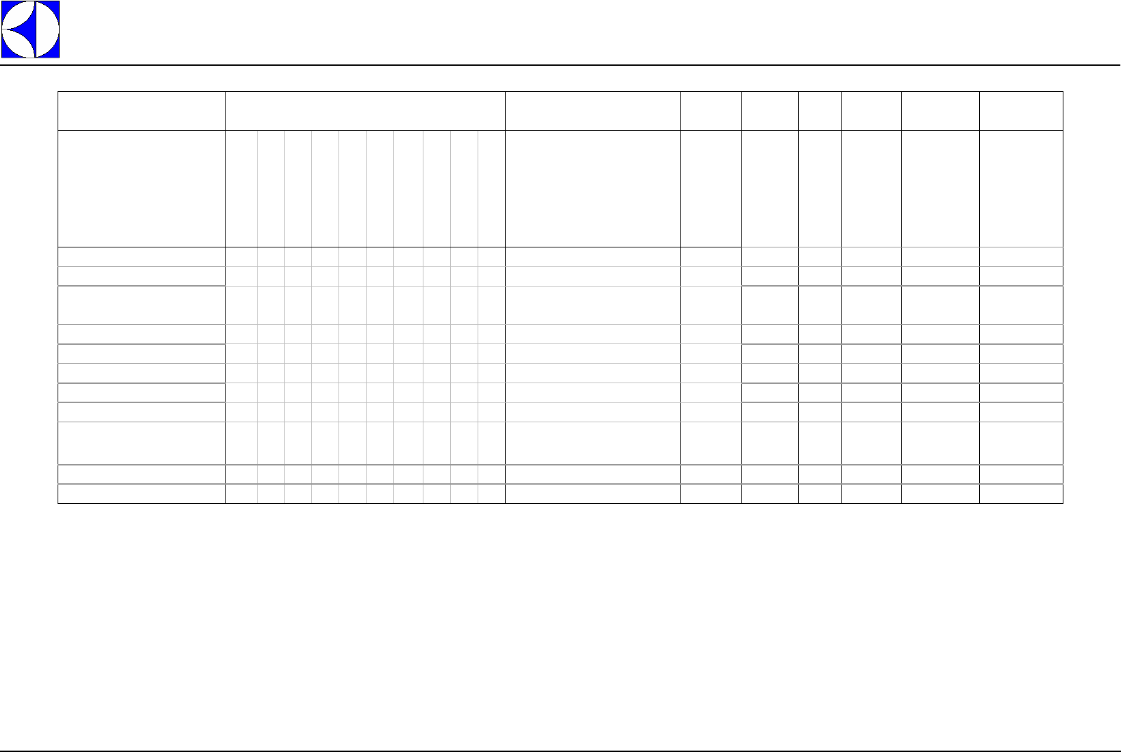
A1 DISPLAY OF AUXILIARY VALUES
From the normal machine operation mode it is possible to see several screens not accessible to the user.
These screens give various machine values, and are accessed by pressing at the same time the combina-
tions of buttons displayed. (Figure ).
Figure 2 Acc
essing current, water volumes and levels display mode
ABCD E
DOC. NO. 5956.677.00 P. 5 / 30
Electrolux
EFS - Dishwashing Systems Platform
Electrolux Professional
Press the Start button - “E” (Figure 1) - and relief blue button - ”D” (Figure 1) - at the same time for a few sec-
onds to access the first screen; press the drain button - “A” (Figure 1) - to access the subsequent screens.
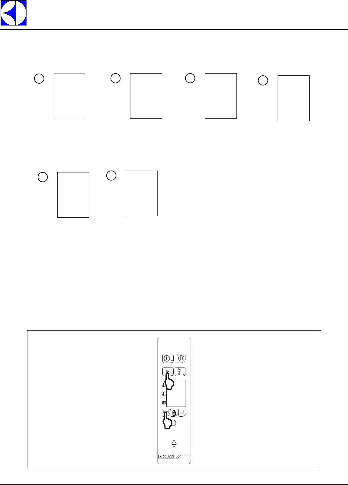
The following screens are displayed ( in order) :
To return to the standard display, wait 30 seconds or press the Confirm button - “C” (Figure 1).
* The parameter UMU (Usa Measurement Unit) is not available on the user interface, but only on the
PC.
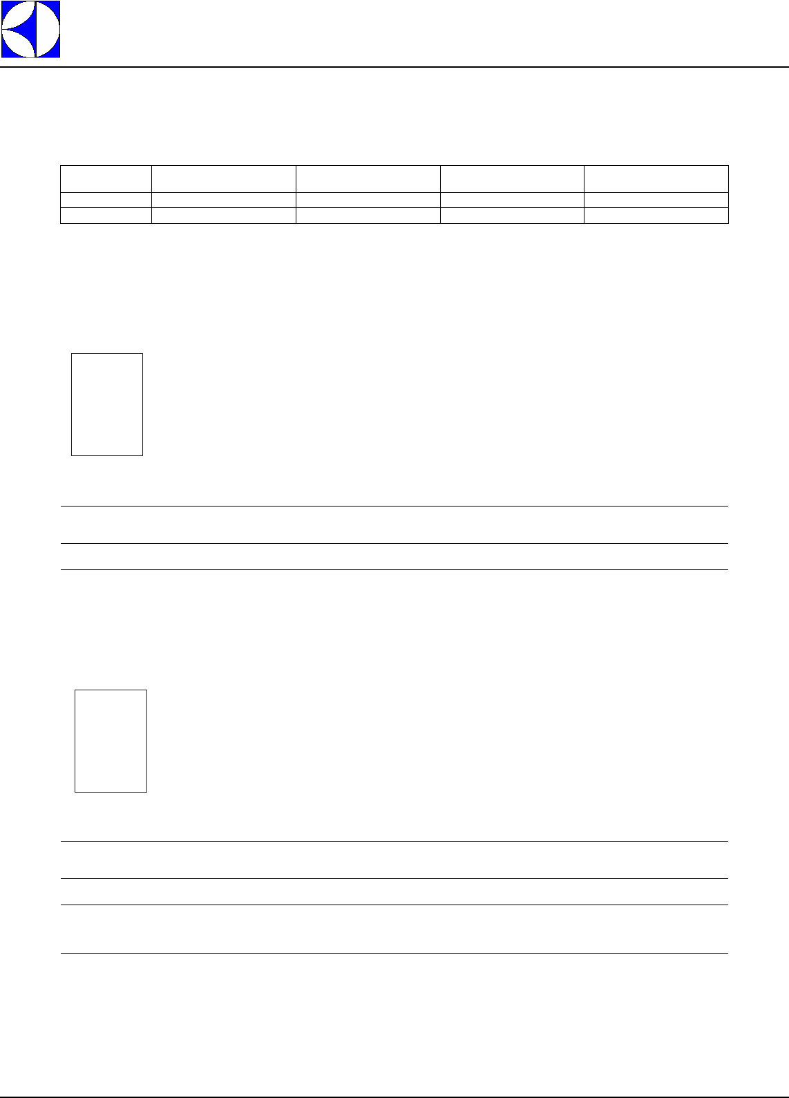
A2 ACCESSING THE USER MENU
From the normal machine operation mode it is possible to access the machine consumption display and reset
menu (Figure 3).
Air Gap level
[Inches if par. UMU = 1; *
mm if par. UMU = 0]
Wash tank level
[Inches if par. UMU = 1; *
mm if par. UMU = 0]
Volume of water contained
in the wash tank
[Gallons if par. UMU = 1; *
Litres if par. UMU = 0]
Prewash tank level
(significant only for
machines with prewash)
[Inches if par. UMU = 1; *
mm if par. UMU = 0]
Volume of water contained
in the prewash tank
(significant only for
machines with prewash)
[Gallons if par. UMU = 1; *
Litres if par. UMU = 0]
Gear motor current
[dec Amperes]
AIG
LE
2.9
1
tAn
LE
6.8
2
tAN
GLN
22.1
3
sCp
LE
6.8
4
sCp
GLn
12.2
5
Mot
Cur
34
6
Electrolux
EFS - Dishwashing Systems Platform
Electrolux Professional
DOC. NO. 5956.677.00 P. 6 / 30
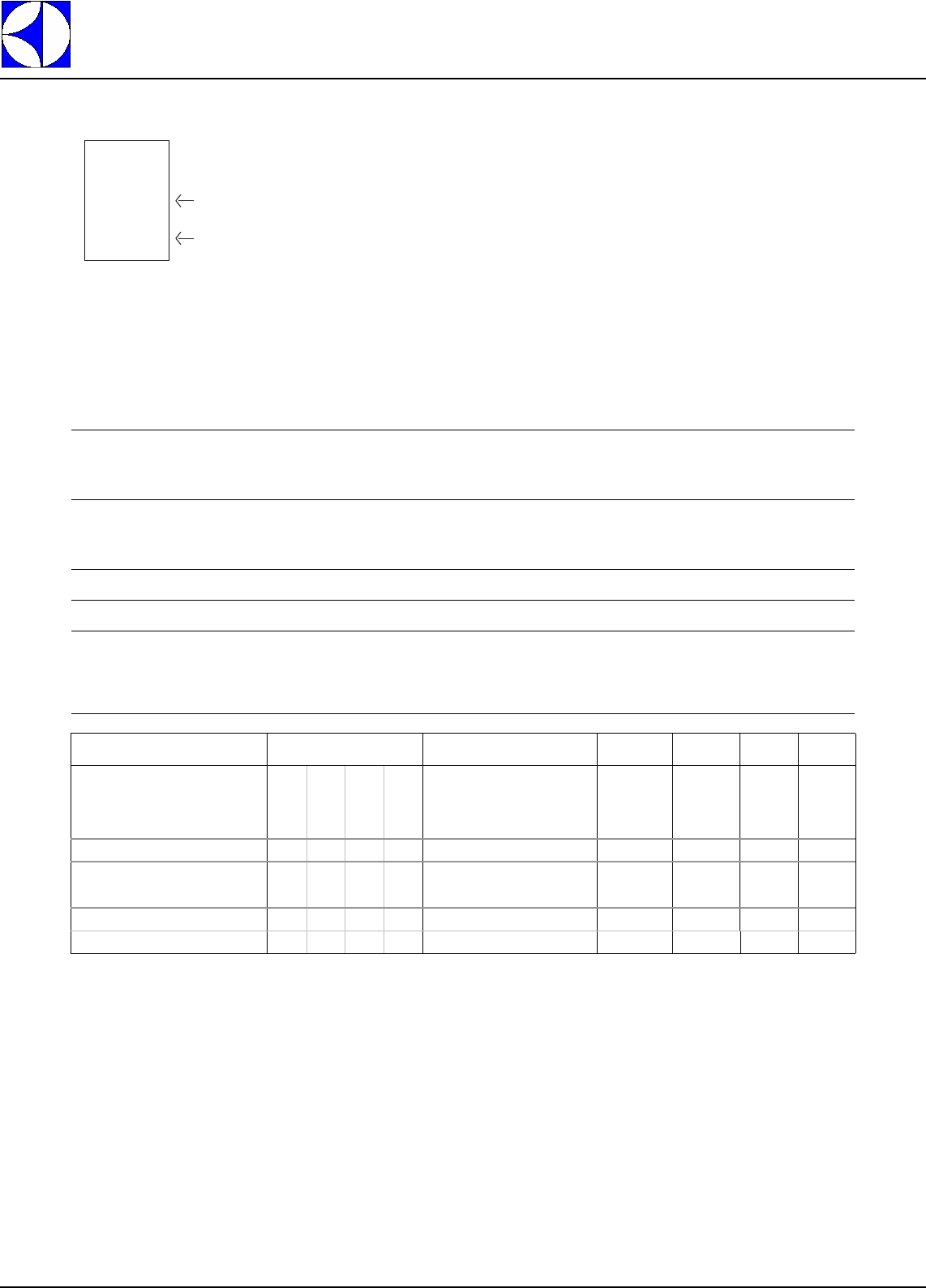
Figure 4 Consuption menu chart
Press the relief blue button (“D” - (Figure 1)) and the drain button (“A” - (Figure 1)) at the same time for several
seconds to access the USER MENU.
The various USER MENU items can be selected by using the drain (“A” - (Figure 1)) and de-lime (“B” -
(Figure 1)) buttons.
A2.1 EXIT
Press the confirm button (“C” - (Figure 1)) when the display indicates the item EXIT (ESC) to return to normal
machine operation.
Press the confirm button (“C” - (Figure 1)) when the selection arrow indicates the item Con (CONSUMP-
TION) and the display will show the counter of the racks processed by the machine.
The number of racks processed and the item to which the number shown refers are displayed alternately. To
obtain the total number of processed racks, form the numbers displayed as follows:
number of racks = 2059165
The display shows the number of racks starting from the date of machine installation. The number of racks
processed starting from a reset operation can also be displayed.
Figure 3
Accessing the
USER MENU
USr (USER MENU)
ESC(EXIT) Con(CONSUMPTION)
USr
ESC
itE
nbr
0
0
168
2
059
165
DOC. NO. 5956.677.00 P. 7 / 30
Electrolux
EFS - Dishwashing Systems Platform
Electrolux Professional
Press Enter to display the resettable counter; in this way the “CONSUMPTION RESET” mode is accessed.
Press the confirm button again to reset the resettable rack counter.
The rack counter is reset.
Press the relief blue button to exit “CONSUMPTION RESET” mode.
Use the drain and de-lime buttons to display the screens relevant to (in order):
- racks number
- rinse time [minutes]
- wash time [minutes]
- sanitisation (or drain or cleaning) cycles counter
- de-lime cycles counter
- machine water consumption [gallons or litres]
- rinse module water consumption [gallons or litres]
- wash module water consumption [gallons or litres]
- prewash module water consumption [gallons or litres]
- machine power absorption [KWH].
All these screens provide for 2 counters, one resettable and the other non-resettable, usable as described above.
In this way it is possible to reset the counters and subsequently check the various counts starting from the date of
the last reset.
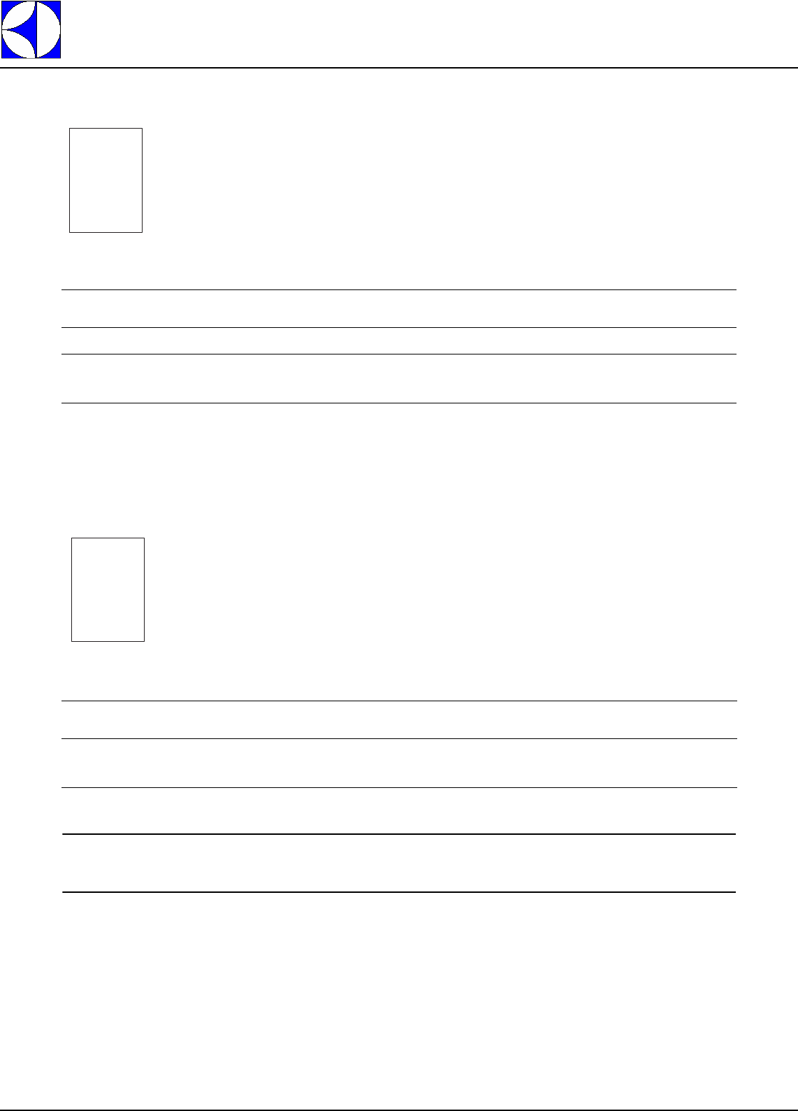
A3 SERVICE MENU
From normal machine operation mode all the parameters and information can be accessed for programming
the electronic boards by pressing the combinations of buttons displayed in (Figure 3) and in (Figure 5).
From the SERVICE MENU it is possible to access the following parameter families and information see
(Figure 5) and (Figure 6) using the drain (“A” - (Figure 1)) and de-lime (“B” - (Figure 1)) buttons to select the
object, the confirm button (“C” - (Figure 1)) to access the selected object and the relief blue button (“D” -
(Figure 1)) to exit the object.
Figure 5
Accessing the
SERVICE MENU
rES
itE
nbr 0
0
20
Electrolux
EFS - Dishwashing Systems Platform
Electrolux Professional
DOC. NO. 5956.677.00 P. 8 / 30
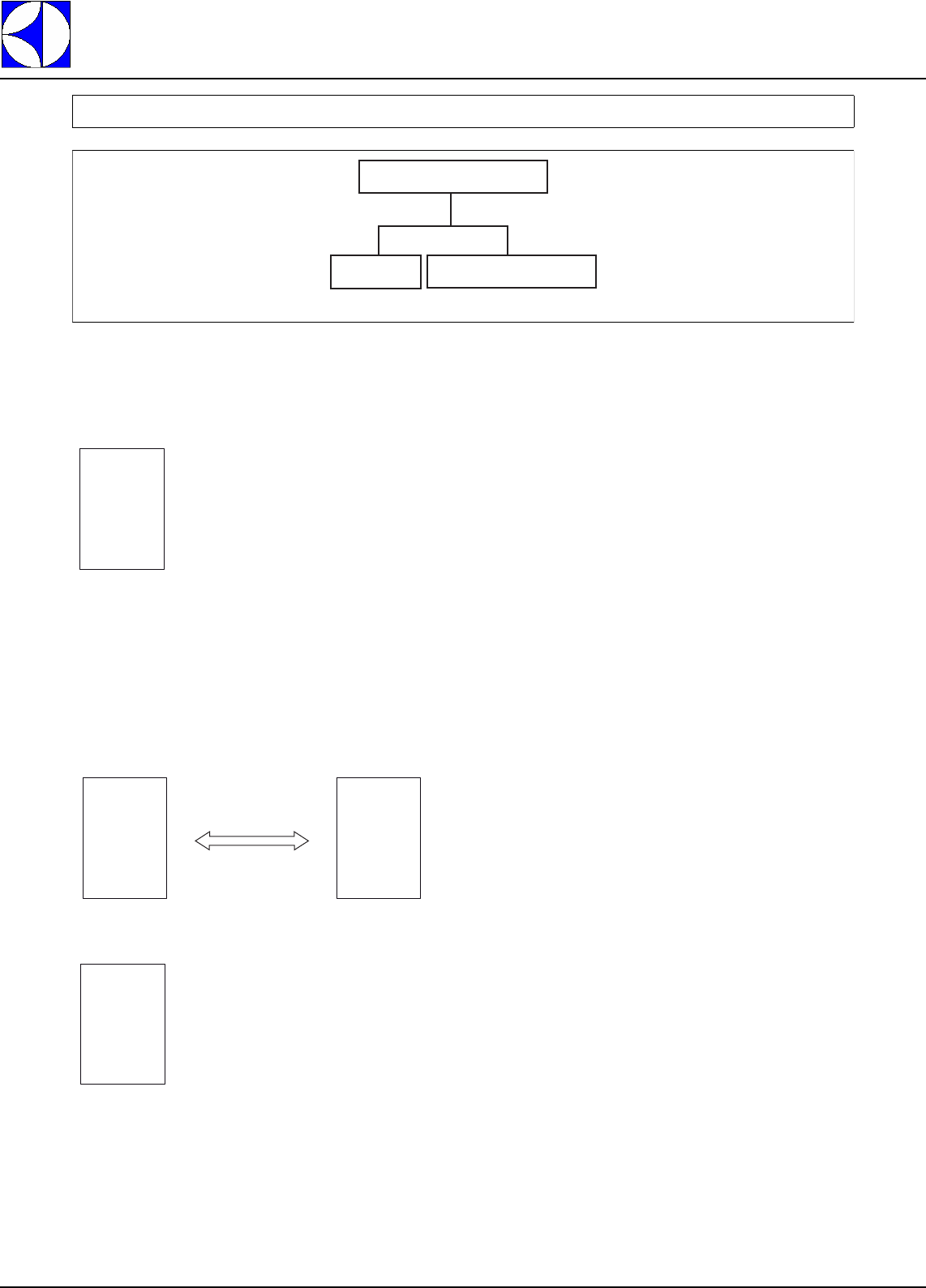
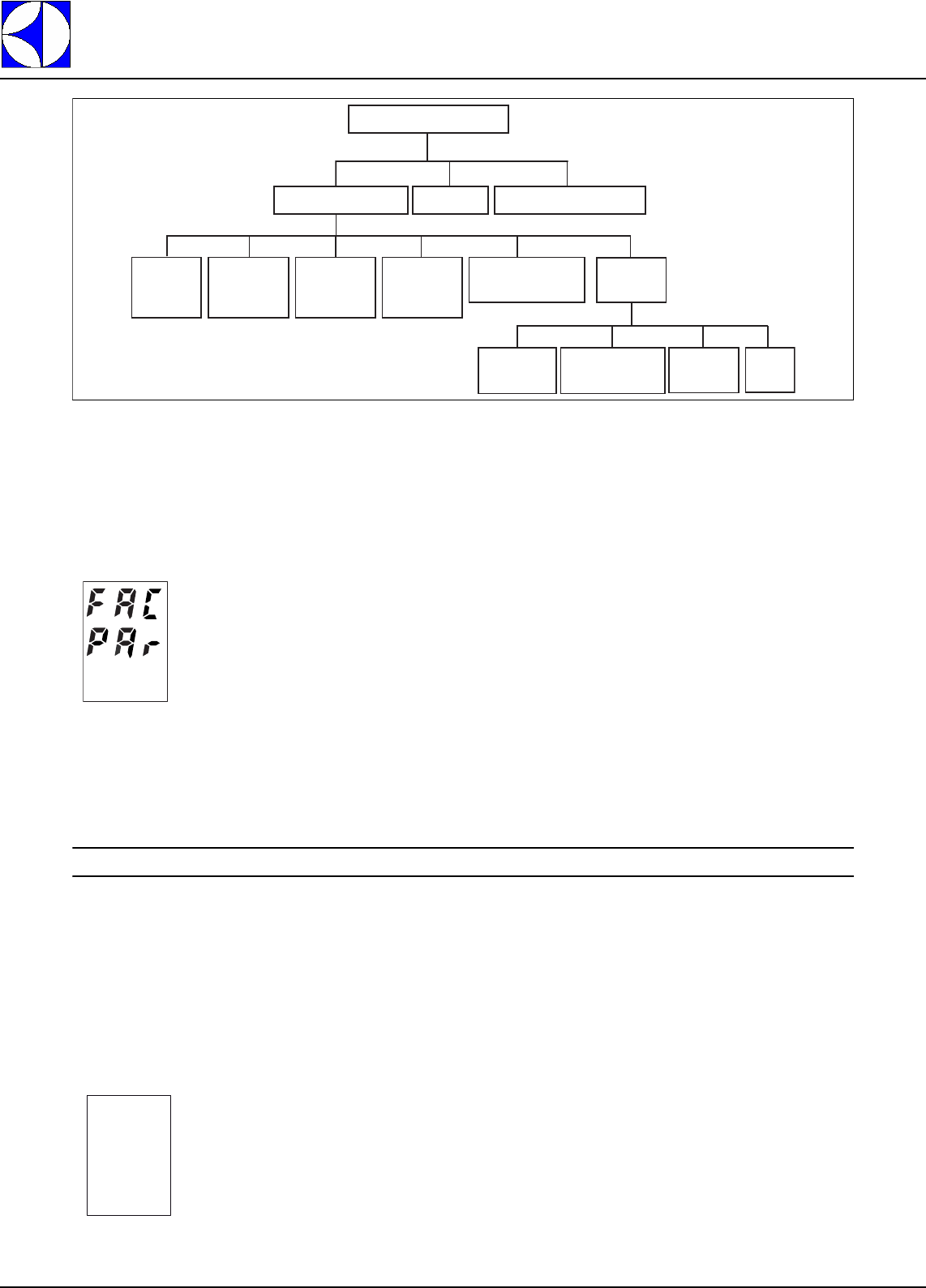
Figure 6
Parameter and function access menu chart
(*) Only for prewash machines.
Press the relief blue button (“D” - (Figure 1)) and the de-lime button (“B” - (Figure 1)) at the same time for sev-
eral seconds to access the SERVICE MENU.
Inside the SERVICE MENU it is possible to:
• display and edit all the machine parameters;
• display information of a general nature, such as the machine software versions;
• adjust the rinse flowrate cock ( just for atmospheric rack type).
WARNING:
After entering the SERVICE MENU switch the machine off and then on again to return to normal operation.
The various SERVICE MENU items can be selected by using the drain (“A” - (Figure 1)) and de-lime (“B” -
(Figure 1)) buttons.
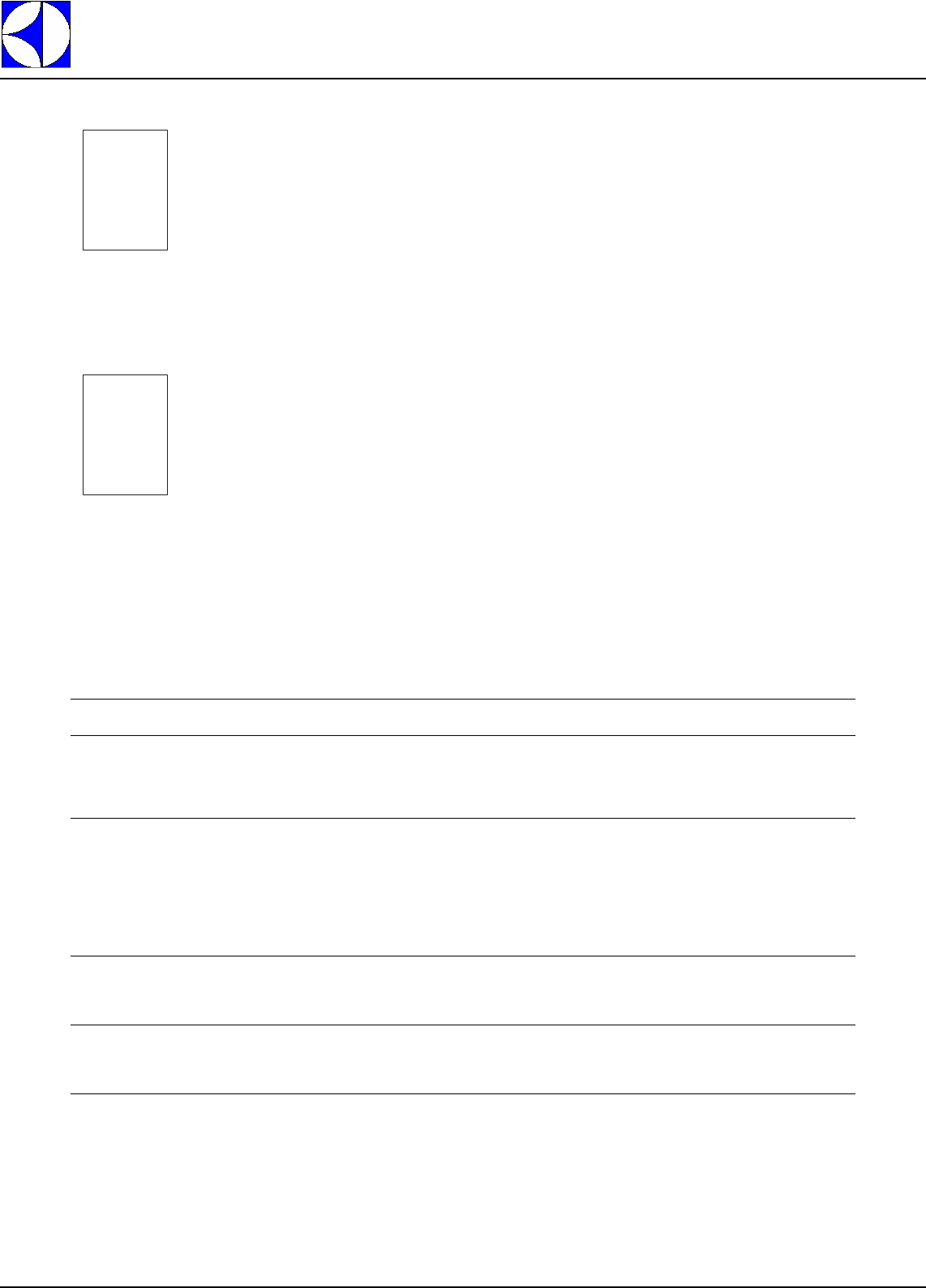
A3.1 PARAMETERS
Press the confirm button (“C” - (Figure 1)) when the display indicates the PARAMETERS item ( PAr) and the
display will show the first family of parameters.
A3.1.1 GENERIC FUNC. ( GFu)
The GENERIC FUNC. family contains parameters that identify several general machine characteristics.
Use the drain and de-lime buttons to select the other parameter families.
Press the relief blue button (“D” -
(Figure 1)
) to display the SERVICE MENU again.
FAC
(SERVICE MENU)
PAr
(PARAMETERS)
rfC
(RINSE CONTROL)
Inf
(INFO)
GFu
(GENERIC
FUNC.)
RiN
(RINSE
MODULE)
tub
(WASH
MODULE)
pRE(*)
(PREWASH
MODULE)
COM
(COMUNICATION)
SUP
(START-UP)
ADJ
(ADJUSTMENT)
SEt
(SET UP)
tSM
(TEST)
APE
(APEX)
fAm
Gfu
DOC. NO. 5956.677.00 P. 9 / 30
Electrolux
EFS - Dishwashing Systems Platform
Electrolux Professional
Press the confirm button (“C” -
(Figure 1)
) to access the first parameter of the
GENERIC FUNCTION
family.
Press the relief blue button (“D” -
(Figure 1)
) to display the
GENERIC FUNCTION
family again.
Use the drain and de-lime buttons to select the other parameters of the GENERIC FUNCTION family.
Press the confirm button to edit the selected parameter: the parameter value starts flashing.
Use the drain (to increase) and de-lime (to decrease) buttons to modify the parameter value. Press the confirm
button to save the new set value. Press the relief blue button to exit without saving the new setting.
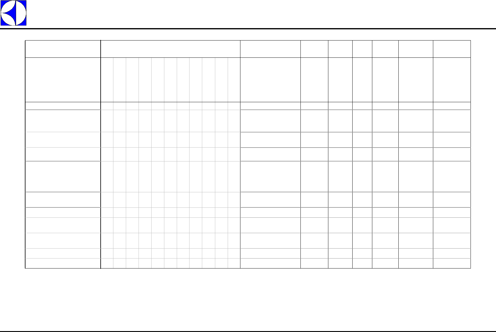
The GENERIC FUNC. / GFu family parameters are described below:
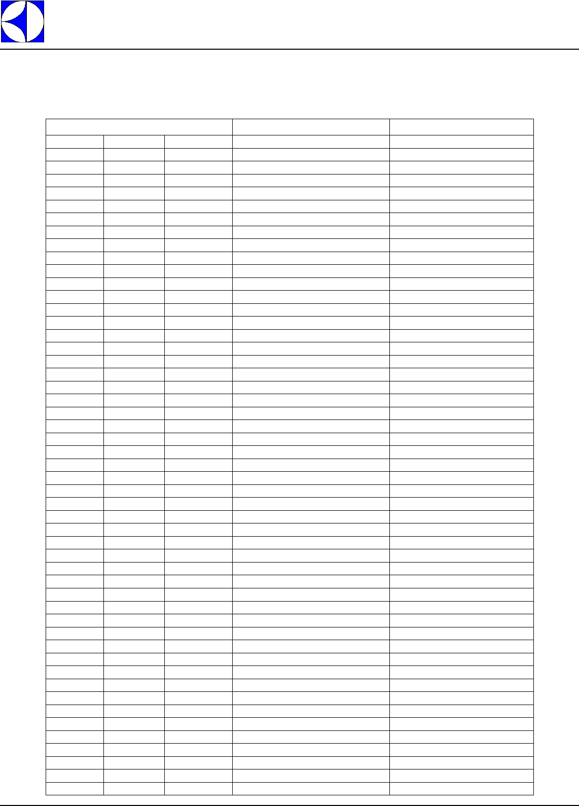
Table 1: Drain cycle: Cleaning mode (ClM) = 0
Current value
Default value
Parame-
ter
namePa-
rameter
name
Display
visualiza-
tion
Family
Nr. Parameter
Nr. Parameter description Unit of
measure Min Max Factory set-
ting [for WT44]
Set
default
par.
spd 1 0 It allows all the parameters to be set to
their default value. The set parameters
are those of a WT44.
The parameter set to “Yes” (1)
automatically returns to “No” (0).
- No/ 0 Yes/
1No/
0
Speed nr.
1SP1 1 3 Indicates racks/hour processed at low
speed. racks/h 24 300 100
Speed nr.
2SP2 1 4 Indicates gear motor operation frequency
at speed 2. racks/h 24 300 200
Cleaning
mode ClM 18Selects the type of machine drain. If
the parameter is set to 0 the machine
carries out airgap and tank drain; if set
to 1 (default value) it carries out
sanitisation; if set to 2 it carries out the
drain and cleaning cycle.
-02 1
Phase Loads Event to evolve to the next
phase Phase dura-
tion [min,sec] Phase dura-
tion [sec] Total Time
[sec] Total Time
[min,sec]
Wash tank
draining valve
Air gap load-
ing valve
Rinse pump
Prewash tank
draining valve
initial pause Fixed time (3 seconds) 0,03 3,00 3 0,03
load the air gap until the working level
is reached (to avoid pump cavitation) X
The air gap level is equal or higher
than the air gap working level
(parameter "Work lev. airgap") 0,00 0,00 3 0,03
drain the air gap X The air gap is completely emptying 1,00 60,00 63 1,03
empty completely the tanks X X Wash tank is completely emptying 1,18 78,00 141 2,21
spd
0
0
DOC. NO. 5956.677.00 P. 10 / 30
Electrolux
EFS - Dishwashing Systems Platform
Electrolux Professional
Table 2: Drain and "sanitisation" hot cleaning cycle: Cleaning mode (ClM) = 1 Æ default
2: the wash tank heatings elements are switched on during this phase only when the wash tank level reached the "Working level"
5: the rinse pump and the tanks loading valve are switched on during these phases only if the tanks level becomes lower than "Drain max. level" - "Max. lev. hister."
Phases duration and water consuption are referred to the following set up: Rinse flow = 7,2 lit/min (1,872 gln/min) and Tank loading valve flow = 20 lit/min (5,2 gln/min)
Phase Loads Event to evolve to the next
phase
Phase
duration
[min,sec]
Phase
duration
[sec]
Total
Time
[sec]
Total
Time
[min,sec]
Water
consumption
(only wash)
Water
consumption
(with prewash)
Wash tank
draining valve
Wash tank loading
valve
Wash pump
Wash heaters
Air gap loading
valve
Rinse pump
Boiler heaters
Prewash tank
draining valve
Prewash tank
loading valve
Prewash pump
Prewash heaters
initial pause Fixed time (3 seconds) 0,03 3,00 3 0,03
load the air gap until the working
level is reached (to avoid pump
cavitation)
X The air gap level is equal or
higher than the air gap
working level (parameter
"Work lev. air gap")
0,00 0,00 3 0,03
drain the air gap and in the same
time drain the tanks
X X X The air gap is completely
emptying
1,46 106,00 109 1,49
empty completely the tanks X X The tanks are completely
emptying
0,11 11,00 120 2,00
reload the tanks until the correct tank
level is reached (parameters "Drain
max. level"); when the tank working
level (parameters "Working level") is
reached the heating of the wash tank
starts
X
X2 X The tanks level is equal or
higher than the tanks filling
level (parameter "Drain max
level")
4,04 244,00 364 6,04 81,33 118,33
the wash tank is heating until set
point (parameter "Sanit. temper.")
X5 X Wash temperature set point
is reached (parameter
"Sanit. temper.")
13,43 823,00 1187 19,47
wash tank sanitization phase X5X X Fixed time (parameter
"Wash san. duration")
1,00 60,00 1247 20,47
drain the wash tank; in the same
time start the prewash tank heating
X XWash tank is completely
emptying
2,12 132,00 1379 22,59
the prewash tank is heating until set
point (parameter "Sanit. temper.")
XPrewash temperature set
point is reached (parameter
"Sanit. temper.")
10,05 605,00 1984 33,04
prewash tank sanitization phase
X5X X Fixed time (parameter "Prew
san. duration")
1,00 60,00 2044 34,04
drain the prewash tank X Prewash tank is completely
emptying
1,05 65,00 2109 35,09
DOC. NO. 5956.677.00 P. 11 / 30
Electrolux
EFS - Dishwashing Systems Platform
Electrolux Professional
Table 3: Drain and cold cleaning cycle: Cleaning mode (ClM) = 2
1: the air gap loading valve is switched on to refill the air gap when the level is lower than "Max. lev. Airgap" - "Max. hist. Airgap"
5: the rinse pump and the tanks loading valve are switched on during these phases only if the tanks level becomes lower than "Drain max. level" - "Max. lev. hister."
Phases duration and water consuption are referred to the following set up: Rinse flow = 7,2 lit/min (1,872 gln/min) and Tank loading valve flow = 20 lit/min (5,2 gln/min).
Phase Loads Event to evolve Phase
duration
[min,sec]
Phase
duration
[sec]
Total
Time
[sec]
Total
Time
[min,sec]
Water
consumption
(only wash)
Water
consumption
(with prewash)
Wash tank draining
valve
Wash tank loading
valve
Wash pump
Wash heaters
Air gap loading valve
Rinse pump
Boiler heaters
Prewash tank draining
valve
Prewash tank loading
valve
Prewash pump
initial pause Fixed time (3 seconds) 0,03 3,00 3 0,03
empty completely the tanks X X The tank are completely emptying 1,19 79,00 82 1,22
load the tanks with fresh water X X1 X
The tanks level is equal or higher than
the tanks filling level ( parameter
"Drain max level")
4,03 243,00 325 5,25 81,00 118,00
clean the tanks with fresh water X5X
X1X X Fixed time (15 seconds) 0,15 15,00 340 5,40
pause between two tanks cleaning Fixed time (5 seconds) 0,05 5,00 345 5,45
clean the tanks with fresh water X5X
X1X X Fixed time (15 seconds) 0,15 15,00 360 6,00
pause between two tanks cleaning Fixed time (5 seconds) 0,05 5,00 365 6,05
clean the tanks with fresh water X5X
X1X X Fixed time (15 seconds) 0,15 15,00 380 6,20
load the air gap until the working
level is reached (to avoid pump
cavitation)
X
The air gap level is equal or higher
than the air gap working level
(parameter "Work lev. airgap")
0,00 0,00 380 6,20
drain the air gap X The air gap is completely emptying 0,45 45,00 425 7,05
empty completely the tanks X X The tank are completely emptying 1,13 73,00 498 8,18
Electrolux
EFS - Dishwashing Systems Platform
Electrolux Professional
DOC. NO. 5956.677.00 P. 12 / 30
The table given below indicates the delay between transit of the rack on the autorinse lever and stopping of
the rinse phase.
E.g. in a WT44 working at high speed (200 racks/h) the rinse pump keeps operating for 3 seconds after the
last rack has released the autorinse lever.
A3.1.2 RINSE MODULE (rin)
The RINSE MODULE family parameters are selected and edited by using the buttons in the same way as that
described for the GENERIC FUNCTION family.
The RINSE MODULE family contains the parameters that identify the rinse module characteristics
The RINSE MODULE / rin family parameters are described below:
A3.1.3 WASH MODULE (tub)
The WASH MODULE family parameters are selected and edited by using the buttons in the same way as that
described for the GENERIC FUNCTION family.
The WASH MODULE family contains the parameters that identify the wash module characteristics
The WASH MODULE / tub family parameters are described below:
A3.1.4 PREWASH MODULE (PrE)
Available only on WT66 with prewash.
The PREWASH MODULE family parameters are selected and edited by using the buttons in the same way as
that described for the GENERIC FUNCTION family.
Capacity speed nr. 1 (racks/
hour) Delay speed nr. 1 (sec) Capacity speed nr. 2 (racks/
hour) Delay speed nr. 2 (sec)
WT44 100 6 200 3
WT66 100 6 200 3
Parame-
ter name Display
visualiza-
tion
Family
Nr. Parameter
Nr. Parameter description Unit of
measure Min Max Factory set-
ting [for WT44]
Boiler
temper. bot 2 4 Boiler temperature set point. °C / °F 10/50 99/
211 86/187
Parame-
ter name Display
visualiza-
tion
Family
Nr. Parameter
Nr. Parameter description Unit of
measure Min Max Factory set-
ting [for WT44]
Tank
temper. tut 3 45 Tank temperature set point. °C / °F 5/42 90/
194 75/167
Autom.
drain del. Atd 3 10 Number of racks passing between two
automatic water changes. If this
parameter is set at zero the function is
disabled.
Racks 0 600 200
FAM
Rin
FAM
tub
DOC. NO. 5956.677.00 P. 13 / 30
Electrolux
EFS - Dishwashing Systems Platform
Electrolux Professional
The PREWASH MODULE family contains the parameters that identify the prewash module characteristics
The PREWASH MODULE / PrE family parameters are described below:
A3.1.5 COMMUNICATION (COM)
The COMMUNICATION family parameters are selected and edited by using the buttons in the same way as
that described for the GENERIC FUNCTION family.
The COMMUNICATION family contains the parameters that identify the COMMUNICATION connection characteris-
tics.
The
COMMUNICATION
/ COM family parameters are described below:
WARNING:
If the parameter AC o is set to 0, management of detergent and rinse aid dosing is completely inhibi-
ted. Set the parameter to 0 to enable communication with the control PC, remembering to set the
parameter to 1 again for normal machine operation.
A3.1.6 APEX PARAMETERS
The Apex family contains the parameters that manage correct dosing of rinse aid and detergent.
The Apex parameter family is divided into 4 subfamilies: Start-up, Adjustment, Set-up and Test. Each subfa-
mily contains several parameters.
Press the confirm button to access the first subfamily of the Apex family (“C” -
(Figure 1)
Parame-
ter name Display
visualiza-
tion
Family
Nr. Parameter
Nr. Parameter description Unit of
measure Min Max Factory set-
ting [for WT44]
Tank
temper. Prt 4 5 Tank temperature set point. °C / °F 5/41 90/
194 10/50
Autom.
drain del. APd 4 11 Number of racks passing between two
automatic water changes. If this
parameter is set at zero the function is
disabled.
Racks 0 600 170
Parameter
name Display
visualiza-
tion
Family
Nr. Parameter
Nr. Parameter description Unit of
measure Min Max Factory set-
ting [for WT44]
Enable
Apex
Communic
ACo 5 2 Enables communication with Apex; to
enable communication with an external
control PC it must be set to 0; set to 1 to
re-enable communication with Apex.
-01 1
FAM
PrE
FAM
COM
Electrolux
EFS - Dishwashing Systems Platform
Electrolux Professional
DOC. NO. 5956.677.00 P. 14 / 30
Use the drain and de-lime buttons to select the other parameter families. Press the blue button (in relief) to
return to the display of the Apex family.
Press the confirm button ("C" -
(Figure 1)
to access the first parameter of the subfamily selected.
Press the blue button (in relief) to return to the display of the subfamily.
To move through the parameters and to edit them, use the same procedures indicated in the GENERIC FUN-
CTION family.
A3.1.6.1 Start-up menu (SUP)
The Startup menu accesses preset formulas to automatically program the dispenser for most common instal-
lations. Typically, no further programming is required after setting up the dispenser in the Startup menu.
The Startup menu
/ SUP
family parameters are described below:
A3.1.6.2 Adjustment menu (probe) (AdJ)
The Adjustment Menu is determined by the Operation Mode chosen in the Startup Menu. Only the Adjustment
Menu appropriate to your system (your default Adjustment Menu) will appear on your screen. This is the
"Inductive probe" adjustment menu.
Parameter
name Display vis-
ualization Family
Nr. Parameter
Nr. Parameter description Unit of
measure Min Max Factory setting
[for WT44]
Operation
mode
OPM 7 0 Specifies if the type of control for
detergent dosing is carried out by
means of a conductivity probe or by
time.
“0” : Inductive probe detergent control;
“1” : Time detergent control.
-01 0
Product pRD 7 1 Specify the product type.
“1” : GPRPI, Solid Power, Solid Power
with Glass Guard.
“2” : GPRPII, Apex Power.
“3” : GPRPIII, Apex Power Plus, Apex
Ultra, Solid Fusion.
“4” : GPRPIV, Solid Metal Fusion.
“5” : GPRPV, Solid Metal Pro.
“6” : GPRPVI, Solid Endurance.
-16 2
Soil level soL 72
Specify the crockeries soil level.
“0”: Light.
“1”: Normal.
“2”: Heavy.
-02 1
Water
hardness
HRD 73
Specify the water hardness.
“0”: Soft.
“1”: Medium.
“2”: Hard.
-02 1
FAM
SUp
OPM
0
0
DOC. NO. 5956.677.00 P. 15 / 30
Electrolux
EFS - Dishwashing Systems Platform
Electrolux Professional
(*) The default values are variables and calculated according to the values set in the parameters "Product"
(Prd), "Soillevel" (SoL) and " Water hardness" (Hrd).
A3.1.6.3 Adjustment menu (time) (AdJ)
The Adjustment Menu is determined by the Operation Mode chosen in the Startup Menu. Only the Adjustment
Menu appropriate to your system (your default Adjustment Menu) will appear on your screen. This is the
"time" adjustment menu.
Parameter
name Display
visualiza-
tion
Family
Nr. Parameter
Nr. Parameter description Unit of
measure Min Max Factory set-
ting [for WT44]
Detergent
set point
dSP 8 0 It indicates the wash tank detergent set
point. The default value of the detergent
set point parameter is based on the
combinations of the following “Start-up
family” parameters: “Product” (Prd), “Soil
level” (SoL) and “Water hardness” (Hrd).
See Table 4: Default Set Points.
ecounits 10 310 27*
Fast
conveyor
rinse pump
speed
FRS 8 1 It indicates the rinse aid peristaltic pump
speed when the conveyor is working at
higher speed (parameter: Speed nr. 2).
See Table 5: Estimated Rinse Volume.
rpm 3,6 36 20
Slow
conveyor
rinse pump
speed
SrS 8 2 It indicates the rinse aid peristaltic pump
speed when the conveyor is working at
lower speed (parameter: Speed nr. 1).
See Table 5: Estimated Rinse Volume.
rpm 3,6 36 15
Detergent
alarm delay
dAD 8 3 This setting delays the out-of-product
alarm from sounding on an initial fill or
wash tank change for the number of
seconds set. It allows the controller to
reach set point before the alarm is
activated. The default value of the
detergent set point parameter is based on
the combinations of the following “Start-
up family” parameters: “Product” (Prd),
“Soil level” (SoL) and “Water hardness”
(Hrd).
sec 1 999 360 *
Parameter
name Display
visualiza-
tion
Family
Nr. Parameter
Nr. Parameter description Unit of
measure Min Max Factory set-
ting [for WT44]
Detergent
initial
charge
dtC 9 0 This setting determines the amount of
time that the detergent will feed on the
initial fill of the dish machine.
sec 1 999 47
Detergent
dose
ddS 9 1 It indicates the time it takes to feed
detergent into the dish machine, on a
preset interval (as set in the ddi menu).
This setting determines the quantity of
detergent is dispensed every rack, every
second rack, or every third rack,
according with the value stored in the
ddi parameter.
sec 1 25,4 4,8
Fast
conveyor
rinse pump
speed
FrS 9 2 It indicates the rinse aid peristaltic pump
speed when the conveyor is working at
higher speed (parameter: Speed nr. 2).
See Table 5: Estimated Rinse Volume.
rpm 3,6 36 20
Slow
conveyor
rinse pump
speed
SrS 9 3 It indicates the rinse aid peristaltic pump
speed when the conveyor is working at
lower speed (parameter: Speed nr. 1).
See Table 5: Estimated Rinse Volume.
rpm 3,6 36 15
Detergent
dose
interval
ddi 9 4 The range of adjustment is 1 to 3 racks, in
increments of 1 rack. Detergent is then
dispensed every rack, every second rack,
or every third rack. One rack interval is
the time the rinse signal is on for
conveyor mode, based on rtM parameter
in Setup family.
racks 1 3 1
Electrolux
EFS - Dishwashing Systems Platform
Electrolux Professional
DOC. NO. 5956.677.00 P. 16 / 30
A3.1.6.4 Setup menu (SEt)
The Setup menu contains dispenser configuration settings that are typically not often reset after initial startup
of the dispenser.
A3.1.6.5 Test menu (tSM)
The Test menu contains Prime/Test Pump and other diagnostic test functions.
Parameter
name Display
visualiza-
tion
Family
Nr. Parameter
Nr. Parameter description Unit of
measure Min Max Factory set-
ting [for WT44]
Detergent
manager
dtM 10 0 Detergent Manager monitors the probe
controlled detergent feed time to reach
set point. When the detergent feed time
exceeds 150% of the setup feed time
during a 12 hour period, Detergent
Manager automatically disables probe
detergent control and enables timed
detergent control. This function is only
available when Probe detergent control is
chosen in “Operatinion mode” (OPM)
parameter on Startup Family.
“0”: Detergent manager off.
“1”: Detergent manager on.
-01 1
Rinse
manager
riM 10 1 Rinse Manager shuts off the rinse pump
when the rinse signal is “unqualified.” An
rinse signal is “unqualified” if no detergent
signal occurred within 90 seconds prior to
the rinse signal.
“0”: Rinse manager off.
“1”: Rinse manager on.
-01 1
Rack time rtM 10 2 It indicates the amount of time the
conveyor takes to travel one rack length.
The value is automatically updated when
the conveyor speed is changed.
sec 1 99 18
Parameter
name Display
visualiza-
tion
Family
Nr. Param-
eter Nr. Parameter description Unit of
measure Min Max Factory set-
ting[for
WT44]
Total dissolved
solid
s
tdS 11 0 This parameter displays the current total
dissolved solids. ppm 0 9999 -
Detergent
setpoint offset
OFS 11 1 This parameter displays the conductivity
offset of the supply water.
Reset Water Conductivity Offset Reading
The Apex Controller allows you to reset the
water conductivity offset reading. To reset:
1. Fill the detergent tank with fresh water
(with no detergent or rinse agent).
2. Select “Detergent Setpoint Offset” (OFS)
parameter from “Apex Family” (APE) -->
“Test” sub-family (tSM); push one time the
“ENTER” push button: the value start to
blink. Press the “ENTER” button again: the
new offset is calculated, stored and shown.
ecounits 0 310 -
Raw
conduttivity
CrA 11 2 This parameter shows raw (not
temperature compensated) probe
conductivity readings.
ecounits 0 310 -
Compensated
conductivity
CAD 11 3 This parameter shows temperature
compensated probe conductivity readings. ecounits 0 321 -
Wash
temperature
ttH 11 4 This parameter shows dish machine wash
temperature readings (conductivity probe
temperature sensor).
°F (or
°C) 32 212 -
Rinse Test rtS 11 6 This parameter is used to manually turn on
the rinse aid peristaltic pump. Pump stops
automatically after 10 seconds.
“0”: No actions.
“1”: Rinse test (programmed speed).
“2”: Rinse test (max speed).
-02 0
Detergent Test dtS 11 5 This parameter is used to manually turn on
the detergent valve. The valve stops
automatically after 10 seconds.
“0”: No actions.
“1”: Detergent test.
-01 0
ESP address Adr 11 7 It is used to set the Ecolab Simple Protocol
ESP Network Address ID number. - 32 127 48
Firmware
version
Fir 11 8 This parameter shows the APEX firmware
version number. - 0 FFFF -
Check sum CsM 11 9
It indicates the six-digit hexadecimal
checksum stored in the APEX flash memory.
--- -
DOC. NO. 5956.677.00 P. 17 / 30
Electrolux
EFS - Dishwashing Systems Platform
Electrolux Professional
The following table shows the default set points for all product groups across all combinations of soil loads and water conditions. It also gives an estimated relation
between Ecounits and drops for all product groups.
Table 4: Default Set Points
All estimated volumes in the following table assume that the standard 1 cc squeeze tube is used. If a larger tube is used, scale up by changing this formula:
Volume (mL) = Squeeze Tube size (cc/rev) x Rinse Speed (rev/min) x rack rinse time (sec) x 1 min/60 sec.
Table 5: Estimated Rinse Volume
GRP I GRP II GRP III
(See NOTE below) GRP IV GRP V GRP VI
SOIL LEVEL /
WATER QUALITY Solid Power, Solid
Power w/Glass Guard Apex Power T1* = Apex (Power Plus & Ultra)
Geo** = Fusion (Solid, Balanced, Power) Solid Metal Fusion Solid Metal Pro Solid Endurance
Light / Soft Ecounits T1 drops Ecounits T1 drops Ecounits *T1 drops **Geo drops Ecounits T1 drops Ecounits T1 drops Ecounits T1 drops
27 12 18 8 15 6 12 15 6 18 12 17 7
Light / Medium
- OR -
Normal / Soft
Ecounits T1 drops Ecounits T1 drops Ecounits *T1 drops **Geo drops Ecounits T1 drops Ecounits T1 drops Ecounits T1 drops
30 13.5 21 9 18 7 13.5 17 6.5 22 13 19 8
Normal / Medium
- OR -
Light / Hard
Ecounits T1 drops Ecounits T1 drops Ecounits *T1 drops **Geo drops Ecounits T1 drops Ecounits T1 drops Ecounits T1 drops
33 15 24 11 21 8.5 16 18 7 26 14 21 9
Normal / Hard
- OR -
Heavy / Medium
Ecounits T1 drops Ecounits T1 drops Ecounits *T1 drops **Geo drops Ecounits T1 drops Ecounits T1 drops Ecounits T1 drops
36 16.5 27 12 24 10 19 20 7.5 30 15 23 10
Heavy / Hard Ecounits T1 drops Ecounits T1 drops Ecounits *T1 drops **Geo drops Ecounits T1 drops Ecounits T1 drops Ecounits T1 drops
40 18 30 14 27 12 24 21 8 34 16 25 11
3.65 7 1012151720222527303236
rpm rpm rpm rpm rpm rpm rpm rpm rpm rpm rpm rpm rpm rpm
7 sec. 0.4 0.6 0.8 1.2 1.4 1.8 2 2.3 2.6 2.9 3.2 3.5 3.7 4.2
10 sec. 0.6 0.8 1.2 1.7 2 2.5 2.8 3.3 3.7 4.2 4.5 5 5.3 6
12 sec. 0.711.422.433.444.455.466.47.2
15 sec. 0.9 1.3 1.8 2.5 3 3.8 4.3 5 5.5 6.3 6.8 7.5 8 9
18 sec. 1.1 1.5 2.1 3 3.6 4.5 5.1 6 6.6 7.5 8.1 9 9.6 10.8
20 sec. 1.2 1.7 2.3 3.3 4 5 5.7 6.7 7.3 8.3 9 10 10.7 12
25 sec. 1.5 2.1 2.9 4.2 5 6.3 7.1 8.3 9.2 10.4 11.3 12.5 13.3 15
Electrolux
EFS - Dishwashing Systems Platform
Electrolux Professional
DOC. NO. 5956.677.00 P. 18 / 30
A3.2 INFO
Press the confirm button (“C” - (Figure 1)) when the display indicates the INFO item(InF) and the machine
firmware (FW) versions will be displayed.
Press the confirm button to return to the SERVICE MENU.
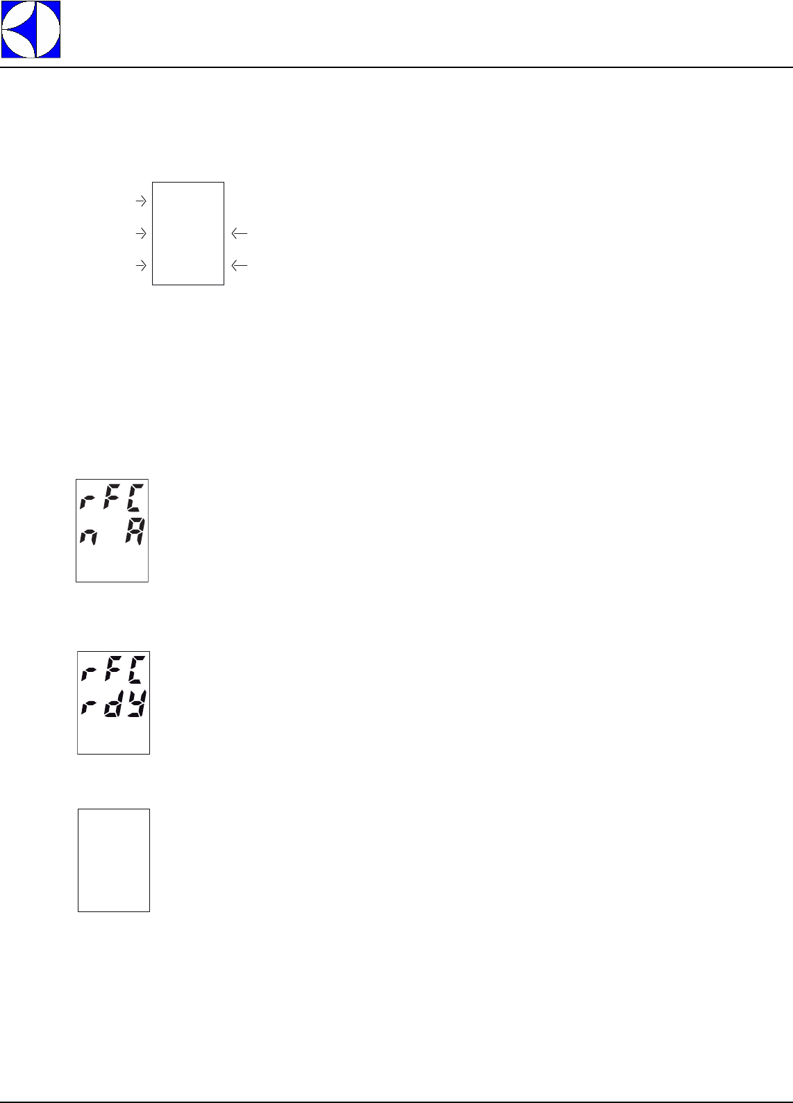
A3.3 RINSE CONTROL
Press the confirm button (“C” - (Figure 1)) when the message rFC appears on the display, and the machine
is going to start a rinse flow control cycle.
If there is a communication error between the rack type boards, the rinse flow control cycle cannot be carried
out.
In this case the display will show:
If the communication is working correctly the dispaly informs the user that the machine is ready to start a rinse
flow control cycle:
Press the confirm button (“C” - (Figure 1)) and a control cycle is started:
WASH + RINSE
PREWASH
USER
POWER
POWER
7.05
7.01
7.01
rfC
pRG
DOC. NO. 5956.677.00 P. 19 / 30
Electrolux
EFS - Dishwashing Systems Platform
Electrolux Professional
Wait about 2 minutes, during which the machine performs a series of air gap filling solenoid valve and rinse
pump activations, until the display will show the actual rinse flow
:
Compare the result obtained with the data given in the table below and if the flow is higher or lower than that
indicated in the table, close or open the rinse flow regulating cock and repeat the control cycle until the opti-
mum value is reached. [Gallons if par. UMU = 1; Litres if par. UMU = 0]
WARNING:
The Rack Type leaves the factory with the cock already adjusted in the optimum position.
WARNING:
The indication of rinse flowrate can be subject to an error of ± 0,3 litres/min.
A4 ACCESSING DATA ON THE CHEMISTRY USED IN THE MACHINE
From the normal machine operation mode it is possible to access the display of Apex low level warnings (rele-
vant to detergent and rinse aid management) and the reading of significant values relevant to the chemistry
used in the machine. To access the Apex data display mode, press at the same time the combination of but-
tons indicated in Figura 7.
MACHINE TYPE CORRECT FLOW (Lit/Min) CORRECT FLOW (Gallons/Min)
WT44 7.2 1.9
WT66 7.2 1.9
Figure 7
Accessing the
APEX INFORMATIONS
rFC
End
1.9

Electrolux
EFS - Dishwashing Systems Platform
Electrolux Professional
DOC. NO. 5956.677.00 P. 20 / 30
Press the START and ENTER buttons together to display of the first Apex warning in progress. The possible
Apex low level warnings are:
Probe failed:
ALr Prb FLt
The conductivity probe reading is outside the permissible reading range.
Probe missing:
ALr Prb MiS
The conductivity probe is disconnected.
Checksum error:
ALr CHS Err
There is no matching between the checksum saved in the APEX memory and that calculated by the firmware.
Rinse pump motor was shorted:
ALr Rin sHr
The rinse aid peristaltic pump motor is short-circuited.
Detergent manager on:
dEt MAn On
The Detergent manager function is operational.
Rinse manager on:
rin MAn On
The Rinse manager function is operational.
Below detergent set point:
BEL dEt SEt
The concentration of detergent in the tank is lower than the set point value.
Use the drain and de-lime buttons to scroll the low level warnings. When the last warning is reached, press the drain button to display the
following read-only parameters:
Total dissolved solid:
tdS
This parameter displays the current total dissolved solids.
Detergent set point offset:
OtS
This parameter displays the conduttivity offset of the supply water.
Raw conductivity:
CrA
This parameter shows row (not temperature compensated) probe conductivity readings.
Compensated conductivity:
CAd
This parameter shows temperature compensated probe conductivity readings.
Wash temperature:
ttH
This parameter shows dish machine wash temperature readings (conductivity probe temperature sensor).
If there are no warnings in progress, the first read-only parameter appears when accessing the Apex data mode.
DOC. NO. 5956.677.00 P. 21 / 30
Electrolux
EFS - Dishwashing Systems Platform
Electrolux Professional
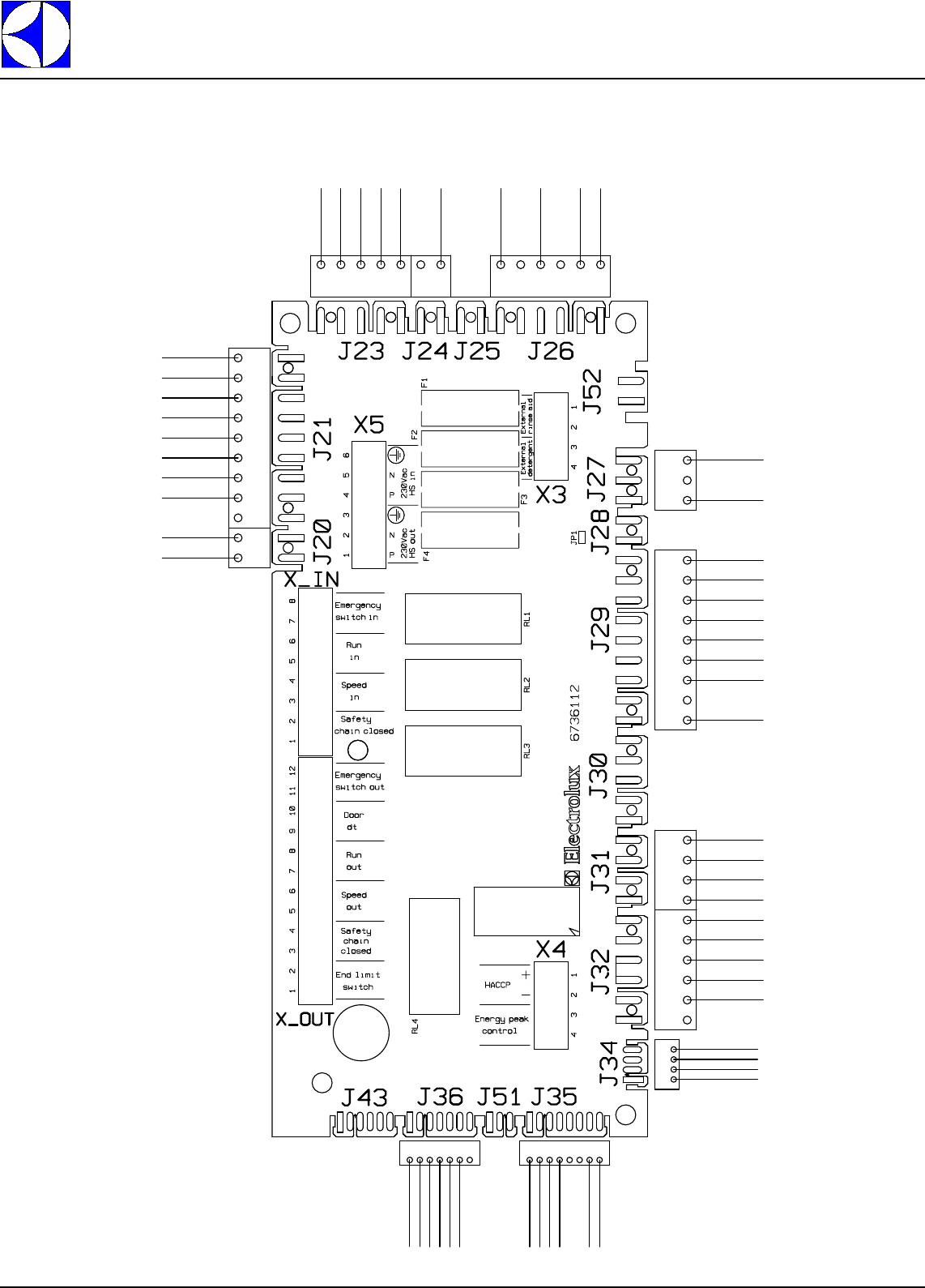
B CONNECTORS LAYOUT
POWER BOARDS CONNECTORS LAYOUT
J21
9
1
1
8
J35
1
4
J34
J36
7
1
2
1
5
1
9
1
2
1
2
1
2
1
6
1
1
3
2
1
9
1
5
1
1
4
6
1
4
1
8
1
3
1
7
1
6
1
Xin
Xout
1
1
J20
2
5
J23
J24
1
J26
1
6
J27
3
1
9
1
J29
4
1
J31
J32
1
6
Electrolux
EFS - Dishwashing Systems Platform
Electrolux Professional
DOC. NO. 5956.677.00 P. 22 / 30
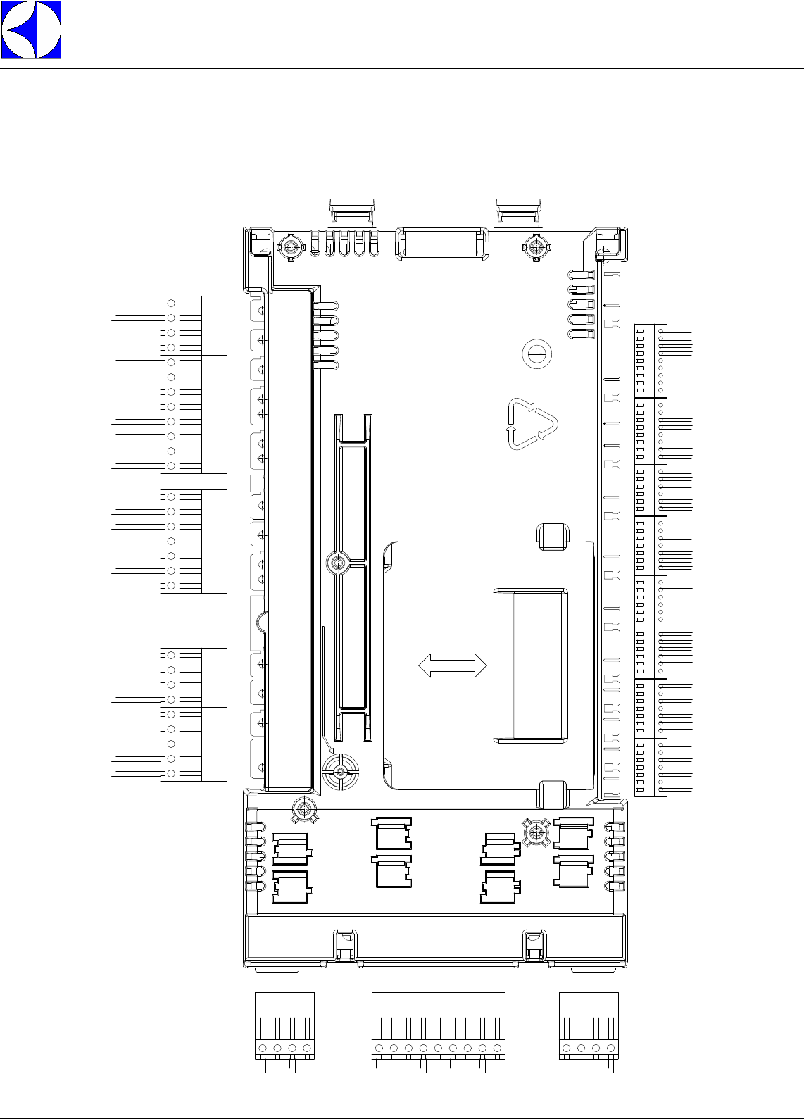
MULTICONNECTOR BOARDS CONNECTORS LAYOUT
6
5
4
3
2
1
9
8
7
10
11
12
9
1
F28
F27
F26
F25
F24
F23
F22
F21
F20
F19
F18
F17
F16
F15
F14
F13
F12
F11
F10
F9
F8
F7
F6
F5
F4
F3
F2
F1
X11
X10
X9
X8X7
X6
X5
X4
X3
X2
X1
F40
F39
F38
F37
F36
F35
F34
F33
F32
F31
F30
F29
00
DOC. NO. 5956.677.00 P. 23 / 30
Electrolux
EFS - Dishwashing Systems Platform
Electrolux Professional
B1 CONNECTORS LAYOUT LEGEND
F 1- F2 Main supply connector
F5-F6 ESD fan connector
F11-F12 Rinse pump connector
F14-F15-F16 Tank filling solenoid valve connector
F18 Tank heating elements connector
F21-F23 Door safety circuit connector
F25-F27 Wash pump connector
F28 Boiler heating elements connector
F29-F30 Drain valve connector
F32-F34 De-lime pump connector
F35-F36 Inverter connector
F39-F40 Airgap filling solenoid valve connector
x1 Temperature sensor connector
x2 Temperature sensor connector
x3 Rinse flowmeter connector
x4 Power measurer connector
x5 Inverter feedback - emergency stop and autostart connector
x6 Board identification connector
x7 Gearmotor current control - airgap pressure sensor connector
x8 Wash flowmeter - gearmotor speed signal connector
x9 Autorinse, thermal protection devices connector
x10 Door switch connector
Electrolux
EFS - Dishwashing Systems Platform
Electrolux Professional
DOC. NO. 5956.677.00 P. 24 / 30
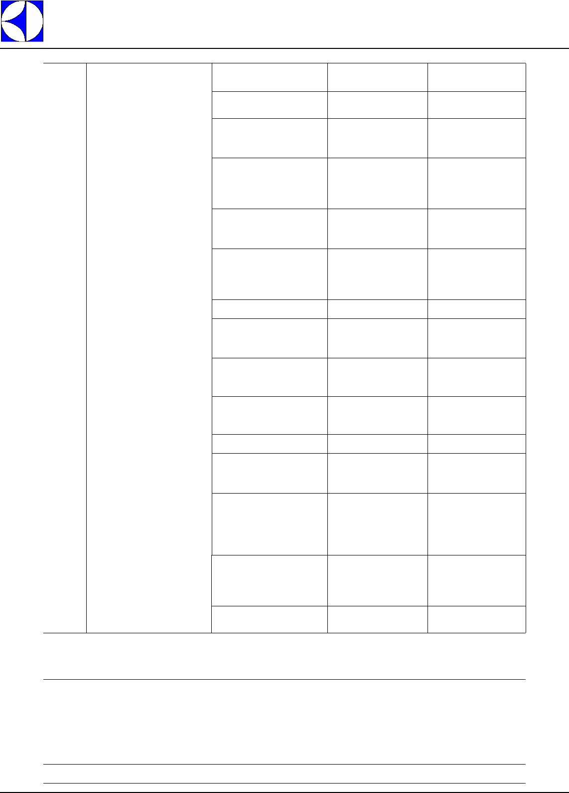
C INVERTER PARAMETERS
WARNING:
When replacing the inverter remove the protection label “A” on the top of the same, as indicated
below (the protection rating becomes IP20).
C1 INVERTER PROGRAMMING
C1.1 DISPLAY FUNCTIONS
C1.2 INVERTER CONTROL TERMINAL ELECTRICAL CONNECTIONS
Figure 8 Inverter electrical connection
KEY
(1) White
(2) Orange
(4) Violet
(5) Red
(7) Black
(8) Yellow
(12) Blue
A
Altivar 11
Telemecanique
ENTESC
3 “7 segment” displays.
Exits a menu or parameter or
aborts the displayed value
to return to the previous value
in the memory.
Returns to the previous menu or
parameter, or increases the
displayed value.
Enters a menu or a parameter,
or saves the displayed
parameter or value.
Goes to the next menu or
parameter, or decreases the
displayed value.
Pressing or does
not store the selection
Save the selection:
The display flashes when a value is
stored.
ENT
RC
RA
0V
AV1
DO
LI1
+15V
(1) (2) (4) (5) (7) (8) (12)
DOC. NO. 5956.677.00 P. 25 / 30
Electrolux
EFS - Dishwashing Systems Platform
Electrolux Professional
C1.3 PARAMETRI DI CONFIGURAZIONE
Inverter Telemecanique AH var 11 type ATV11PU12M2E380
Parameters for 110Vac gearmotor (Delta connection)
Parameter Description Standard machine
ACC Acceleration ramp time 3.0
dEC Deceleration ramp time 0.5
LSP Low speed 0.0
HSP High speed 100
ItH Motor thermal current 3.6
SP2 2nd preset speed 10
SP3 3rd preset speed 25
SP4 4th preset speed 50
Alt Act Scale of analog input 10U
drC UnS Nominal motor voltage 110
FrS Nominal motor frequency 50
StA Frequency loop stability 20
FLG Frequency loop gain 50
UFr Ir compensation 50
nCr Nominal motor current 3.6
CLI Current limit 3.9
nSL Nominal motor slip 5
SLP Slip compensation 100
COS Nominal motor cosine 0.65
FUn tCC ACt Type of control 2C
tCt Type of two wire control Lel
rrS Reverse nO
Ps2 LIA Preset speed lia nO
LIB Preset speed lib nO
HSP LIA Config. input Lia nO
LIB Config. input Lib nO
tLS 0.0
PI PIF nO
LOC Overload threshold 90
tOL Time delay for overl. func. 0
API Histeresis freq. reached 0.3
LUL Underload threshold 60
tUL Time delay for underl. func. 10
rSF Fault reset nO
rP2 LI Second ramp nO
LC2 LI 2nd limit current nO
nST Freewheel stop nO
StP Controlled stop on loss of line FST
brA Deceleration ramp adaptation YES
AdC ACt Automatic dc injection YES
tdC Injection time on stopping 0.5
SdC Injection current 2.9
SfT ACt Frequency range LF
Sfr Switching frequency 4
FLr Catch on the fly nO
dO ACt Analogic output do OCr
Atr Automatic restart nO
bFr Motor frequency 50
SCS Configuration backup nO
FCS Reminder of the configuration nO
Electrolux
EFS - Dishwashing Systems Platform
Electrolux Professional
DOC. NO. 5956.677.00 P. 26 / 30
D WARNING MESSAGES AND TROUBLESHOOTING
List of possible documented machine alarms:
CODE DESCRIPTION POSSIBLE CAUSE
11 The Air Gap was not completely
filled within the max. filling time. - The air gap water supply cock is not open.
- The water filling solenoid valve doesn’t work properly.
- The water feed flow is too low.
- The water inlet filter is not clean.
- The boiler pressure sensor doesn’t work properly.
12 The pressure sensor on the air gap
does not work correctly. - The pressure sensor on the air gap doesn’t work properly.
- The pressure sensor connector on the air gap is not correctly inserted.
- The X7 connector on the rinse board is not correctly inserted.
15 *The required temperature was not
reached in the boiler within the max.
heating time.
- The rinse water flow is too high.
- A heating element or a heating element branch doesn’t work properly.
- The CU is not clean.
- The boiler temperature sensor doesn’t work properly.
- The boiler heating element starter controller doesn’t work properly or its coil is not correctly
connected to the rinse board.
- The CU fan does not work properly.
16 The water temperature in the boiler
is too high. - The “Boil. temp. start” parameter (bt5) or the “Boiler temper.” parameter (bot) has been
changed.
- The relay that activates the boiler heating elements starter controller is stuck.
17 The boiler temperature sensor is
short-circuited. - The boiler temperature sensor is short-circuited.
18 The boiler temperature sensor is
open. - The boiler temperature sensor is open or disconnected.
- The boiler temperature sensor connector is not correctly inserted.
- The connector on the rinse board is not correctly inserted.
23** The rinse pump thermal protector
has tripped. - The rinse pump doesn’t work properly.
- The rinse pump impeller is blocked.
- The rinse circuit is clogged.
- The rinse flowmeter works properly.
DOC. NO. 5956.677.00 P. 27 / 30
Electrolux
EFS - Dishwashing Systems Platform
Electrolux Professional
27 The gear motor inverter has
generated an allarm. - The inverter or the gear motor
doesn’t work properly. Possible
machine alarms documented on Possible cause Remedy
1) OCF overcurrent - ramp too short
- inertia or load too high
- mechanical locking
- check the state of the
mechanism.
2) SCF motor short circuit - insulation fault or short-
circuit at the drive output - check the cables
connecting the drive to the
motor , and the motor
insulation.
3) InF internal fault - internal fault - check the environment
(electromagnetic
compatibility).
- send the drive to be
checked/repaired.
4) CFF configuration fault - The current configuration is
inconsistent
- some parameters in the
inverter have been
- return to factory settings.
5) SOF overspeed - instability or
- driving load too high
- some parameters in the
inverter have been
modified
- return to factory settings.
6) CrF internal fault - load relay control fault or
damaged load resistor - replace the drive.
7) OHF drive overload - drive temperature too high - check the motor load and
the enviroment.Wait for the
drive to cool down before
restarting.
8) OLF motor overload - triggered by motor current
too high - check the motor load. Wait
for the drive to cool down
before restarting.
9) OSF overvoltage - line voltage too high
- disturbed line supply - check the line voltage. The
overvoltage thresold is 415
V on the DC bus.
10) ObF overvoltage during
deceleration - braking too sudden or
driving load. - increase the deceleration
time.
11) PHF line phase failure - drive incorrectly supplied
or a fuse blown
- failure of one phase
- unbalanced load
- check the power
connection and the fuses.
- reset.
12) USF undervoltage - line supply too low
- transient voltage dip
- damaged load resistor
- check the voltage and
the voltage parameter.
The undervoltage
threshold is 230 V on the
DC bus.
- replace the drive.
13) ULF Current level above the
overload threshold LOC.- Check the value of the
parameters LOC and tOL
in the menu FUn.
- Check the mechanics
(wear, mechanical stops,
lubrication, obstacles, etc.).
14) ULC Current level below the
under-load threshold LUL.- Check the value of the
parameters LUL and tUL
in the menus FUn.
30 ** The Air gap was not completely
emptied within the max. emptying
time.
- The impeller rotation is wrong.
- The non return valve on the air gap doesn’t work properly.
- The pressure sensor on the air gap doesn’t work properly.
- The air gap air trap is not clean.
31 The wash tank was not completely
filled within the max. filling time. - The wash tank water supply cock is not open.
- The water load solenoid valve doesn’t work properly.
- The water feed flow is too low.
- The water inlet filter is not clean.
- The pressure sensor on the wash tank doesn’t work properly.
- The wash tank overflow has not been inserted.
- The wash tank drain solenoid valve doesn’t work properly and remains open.
- The pressure sensor on the wash board doesn’t work properly.
- The wash board doesn’t work properly.
32 The pressure sensor on the wash
tank does not work correctly. - The pressure sensor on the wash board doesn’t work properly.
- The wash board doesn’t work properly.
Electrolux
EFS - Dishwashing Systems Platform
Electrolux Professional
DOC. NO. 5956.677.00 P. 28 / 30
33 *The required temperature in the
wash tank was not reached within
the max. heating time.
- A heating element or a heating element branch of the wash board doesn’t work properly.
- The wash tank temperature sensor doesn’t work properly.
- The wash tank heating element starter controller doesn’t work properly or its coil is not correctly
connected to the rinse board.
34 The water temperature in the wash
tank is too high. - The “Tank temper.” parameter (tut) or the “Sanit. temper.” parameter (tSt) has been
changed.
- The relay that activates the wash tank heating elements starter controller is stuck.
35 The wash tank temperature sensor
is short-circuited. - The wash tank temperature sensor is short-circuited.
36 ** The wash tank temperature sensor
is open. - The wash tank temperature sensor is open or disconnected.
- The wash tank temperature sensor connector is not correctly inserted.
- The connector on the wash board is not correctly inserted.
37 *** The wash pump thermal protector has
tripped - The wash pump thermal protector is not correctly set.
- The wash pump doesn’t work properly.
- The wash pump impeller is blocked.
40 ** The wash tank was not completely
emptied within the max. emptying
time.
- The drain is blocked.
- The drain solenoid valve doesn’t work properly.
- The wash tank air trap is not clean.
51 The prewash tank was not
completely filled within the max.
filling time.
- The prewash tank water supply cock is not open.
- The water load solenoid valve doesn’t work properly.
- The water feed flow is too low.
- The water inlet filter is not clean.
- The load solenoid valve filter is not clean.
- The prewash tank pressure sensor doesn’t work properly.
- The prewash tank overflow has not been inserted.
- The prewash tank drain solenoid valve doesn’t work properly and remains open.
- The pressure sensor on the prewash board doesn’t work properly.
- The prewash board doesn’t work properly.
52 The pressure sensor on the prewash
tank does not work correctly. - The pressure sensor on the prewash board doesn’t work properly.
- The prewash board doesn’t work properly.
53 ** The required temperature in the
prewash tank was not reached within
the max. heating time.
- A heating element or a heating element branch of the prewash board doesn’t work properly.
- The prewash tank temperature sensor doesn’t work properly.
- The prewash tank heating element starter controller doesn’t work properly or its coil is not
correctly connected to the rinse board.
54 The water temperature in the
prewash tank is too high. - The “Tank temper.” parameter (Prt) or the “Sanit. temper.” parameter (PSt) has been
changed.
- The relay that activates the wash tank heating elements remote control switch is stuck.
55 The prewash tank temperature
sensor is short-circuited. - The prewash tank temperature sensor is short-circuited.
56 ** The prewash tank temperature
sensor is open. - The prewash tank temperature sensor is open or disconnected.
- The prewash tank temperature sensor connector is not correctly inserted.
- The connector on the prewash board is not correctly inserted.
57 ** The prewash pump thermal
protector has tripped. - The prewash pump thermal protector is not correctly set.
- The prewash pump doesn’t work properly.
- The prewash pump impeller is blocked.
- The “Prewash module” parameter (PtY) is not correctly set.
58 ** The prewash tank was not
completely emptied within the max.
emptying time.
- The drain is blocked.
- The drain solenoid valve doesn’t work properly.
- The prewash tank air trap is not clean.
DOC. NO. 5956.677.00 P. 29 / 30
Electrolux
EFS - Dishwashing Systems Platform
Electrolux Professional
* If the value of the parameter "Heat tim. enable" (HtE) is "Yes" (1), the machine stops when this alarm
appears. If the parameter value is "No" (0), the machine does not shut down when this alarm appears.
** The machine does not shut down if these alarms appear. Every 8 seconds a message indicating the
alarm number is shown on the display. A red LED blinks, but the machine continues to carry out the normal
operations.
*** This alarm causes machine stop in versions without prewash. In prewash versions the machine continues
to work.
76 The gear motor supplied current is
higher than the maximum value
allowed for the gear motor current.
- The wire connected from the inverter ( Do terminal block) to the elctronic board (X7-5) is short-
circuited with the ground.
- The inverter parameters are not correctly set.
77 The gear motor supplied current is
lower than the minimum value
allowed for the gear motor current.
- The wire connected from the inverter ( Do terminal block) to the electronic board (X7-5) is open.
- The inverter parameters are not correctly set.
- The gear motor is configured with star connection and it must be configured with delta
connections.
89 The temperature on the user
interface is too high. - Presence of steam too hot on the user interface board.
- The user interface doesn’t work properly.
101 ** The power absorbed by the boiler
heating elements is less than the
foreseen rated power.
- One or more branches of the boiler heating elements are disconnected.
- One or more remote control switches that control the boiler heating elements do not work
properly.
- The relay of the MEC board that supplies the boiler heating element remote control switch coils
does not work properly.
- The connection wiring between the remote control switches and the boiler heating elements or
between the MEC board and the boiler heating element remote control switch coils is
disconnected.
- The parameter Pulse/KWatt Hour (EnP) is not correctly set.
- The energy meter connections are not correct.
102 ** The power absorbed by the wash
tank heating elements is lower than
the foreseen rated power.
- One or more branches of the boiler heating elements are disconnected.
- One or more remote control switches that control the wash tank heating elements do not work
properly.
- The relay of the MEC board that supplies the wash tank heating element remote control switch
coils does not work properly.
- The connection wiring between the remote control switches and the boiler heating elements or
between the MEC board and the wash tank heating element remote control switch coils is
disconnected.
- The parameter Pulse/KWatt Hour (EnP) is not correctly set.
- The energy meter connections are not correct.
103 ** The power absorbed by the prewash
tank heating elements is lower than
the foreseen rated power.
- One or more branches of the boiler heating elements are disconnected.
- One or more remote control switches that control the prewash tank heating elements do not work
properly.
- The relay of the MEC board that supplies the prewash tank heating element remote control switch
coils does not work properly.
- The connection wiring between the remote control switches and the prewash tank heating
elements or between the MEC board and the prewash tank heating element remote control switch
coils is disconnected.
- The parameter Pulse/KWatt Hour (EnP) is not correctly set.
- The energy meterconnections are not correct.
CoM
Err
(compact
machines)
Communication problems between
machine electronic boards. - The bus connection cables are not correctly connected to all the boards.
- One or more boards don’t work properly.
- The “Appl. type” parameter (APt) is not correctly set.
- Connector X6 is not correctly inserted in the MEC boards.
When alarm COM Err appears, the display will show the number of the electronic board that
generated the communication error.
2: wash + rinse
3: prewash
If, after a communication error, the machine is able to re-enable the communication between the
boards, the following message appears on the display:
No
CoM
Err
Electrolux
EFS - Dishwashing Systems Platform
Electrolux Professional
DOC. NO. 5956.677.00 P. 30 / 30
E LACK OF DETERGENT AND RINSE AID WARNINGS
ALr
rnS
Out
Lack of rinse aid
The lack of rinse aid warning is generated when a rinse cycle is in progress and the optical sensors
(emitter and receiver) installed in the dispenser detect the absence of the cartridge.
ALr
dEt
Out
Lack of detergent
The lack of detergent warning is generated when a wash cycle is in progress and the conductivity
sensor installed in the tank detects that for 6 minutes (parameter dAd Detergent alarm delay) the
concentration of detergent in the tank is below the set point value, and more precisely when
Compensated conductivity < Detergent set point + Detergent set point offset. If the concentration of
detergent in the tank is below the set point, the low level warning (not visible to the user) is
immediately generated, but if after 6 minutes the concentration continues to remain low, the
message visible to the user is generated.
