Electrolux Liquid Propane Condensing Tankless Water Heater Ep19Wi30Ls Installation Instructions
2015-03-28
: Electrolux Electrolux-Liquid-Propane-Condensing-Tankless-Water-Heater-Ep19Wi30Ls-Installation-Instructions-662766 electrolux-liquid-propane-condensing-tankless-water-heater-ep19wi30ls-installation-instructions-662766 electrolux pdf
Open the PDF directly: View PDF ![]() .
.
Page Count: 84
EN CONDENSING TANKLESS GAS WATER HEATER Installation Manual
SBB800T-1
Rev. 09/13
*SBB800T*
SP CALENTADOR A GAS TIPO CONDENSADO Manual de Instalación
5995615357 September 2013
Installation Manual
CONDENSING TANKLESS GAS WATER HEATER
EN19WI30LS
EP19WI30LS
Potential dangers from accidents during installation and use are divided into the following three
categories. Closely observe these warnings, they are critical to your safety.
Prohibited Disconnect
Power Ground Be sure to do
WARNING: If the information in this manual is not followed exactly, a re or explosion may result
causing property damage, personal injury or death.
DANGER indicates an imminently hazardous situation which,
if not avoided, will result in death or serious injury.
WARNING indicates a potentially hazardous situation which,
if not avoided, could result in death or serious injury.
CAUTION indicates a potentially hazardous situation which,
if not avoided, may result in minor or moderate injury.
DANGER
WARNING
CAUTION
Requests to Installers
r*OPSEFSUPVTFUIFXBUFSIFBUFSTBGFMZSFBEUIJTJOTUBMMBUJPONBOVBMDBSFGVMMZBOEGPMMPXUIF
installation instructions.
r'BJMVSFTBOEEBNBHFDBVTFECZFSSPOFPVTXPSLPSXPSLOPUBTJOTUSVDUFEJOUIJTNBOVBMBSFOPU
covered by the warranty.
r
$IFDLUIBUUIFJOTUBMMBUJPOXBTEPOFQSPQFSMZJOBDDPSEBODFXJUIUIJT*OTUBMMBUJPO.BOVBMVQPODPNQMFUJPO
r
"GUFSDPNQMFUJOHJOTUBMMBUJPOQMFBTFFJUIFSQMBDFUIJT*OTUBMMBUJPO.BOVBMJOBQMBTUJDQPVDIBOE
attach it to the side of the water heater (or the inside of the pipe cover or recess box if applicable),
or hand it to the customer to retain for future reference. Also, be sure to ll in all of the required
items on the registration/warranty card and to hand the registration/warranty card to the customer
BMPOHXJUIUIF6TFBOE$BSF.BOVBM
CAUTION
'0364&*/3&4*%&/5*"-"11-*$"5*0/4*/5)&6/*5&%45"5&40/-:
/05*/5&/%&%'0364&*/$"/"%"03.&9*$0
Installation must conform with local codes, or in the absence of local codes,
UIF/BUJPOBM'VFM(BT$PEF"/4*;/'1"MBUFTUFEJUJPO
&MFDUSPMVY)PNF1SPEVDUT*ODSFTFSWFTUIFSJHIUUPEJTDPOUJOVFPS
change at any time, the designs and/or specications of its products
without notice.
Low NOx
Approved by
4$"2.%
OH+PSQQN
(Natural Gas Only)

1.
Included Accessories
The following accessories are included with the unit.
$IFDLGPSBOZNJTTJOHJUFNTCFGPSFTUBSUJOHJOTUBMMBUJPO
Q’ty
ShapePart
Anchoring Screw 1
each
Part Shape Q’ty
1
Remote Controller
(See page 31)
Remote Controller
$PSEGUN
3$$03%
1
2.
Optional Accessories
The accessories listed below are not included with
the units, but may be necessary for installation.
$POUBDU&MFDUSPMVY)PNF1SPEVDUT*ODBU
GPSGVSUIFSJOGPSNBUJPO
ShapePartPart Shape
2VJDL$POOFDU$PSE
58)2$$03%
6TFBOE$BSF.BOVBM
8BSSBOUZ*OTUBMMBUJPO.BOVBM
(this document)
NN17$5FSNJOBM
58))03$0/$
NNNN
)PSJ[POUBM)PPE
Termination
58))03)00%
NNNN
7FSUJDBM3BJO$BQ
Termination
58)7&35$"1
)PSJ[POUBM*OTUBMMBUJPO,JU
58))03,*5
*TPMBUJPO7BMWFT
1SFTTVSF3FMJFG7BMWF
)PSJ[POUBM)PPE
Termination,
47$POWFSTJPO,JU
(47$,)
7FSUJDBM*OTUBMMBUJPO,JU
58)7&35,*5
*TPMBUJPO7BMWFT
1SFTTVSF3FMJFG7BMWF
7FSUJDBM3BJO$BQ
Termination,
47$POWFSTJPO,JU
(47$,)
/FVUSBMJ[FS,JU
58)/&653"-
3
G
Quick Connect
Cor
d
Remote Controller Cord Gas Supply Piping
Cold Water Supply
Hot Water
Remote Controller
Terminal Block
Cord
Connector
Cord
Connector
3.
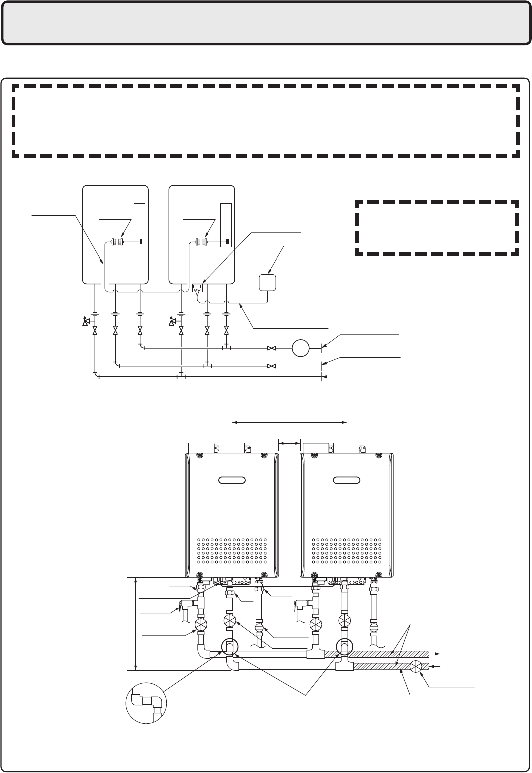
Quick Connect Multi System Installation
r5IF2VJDL$POOFDU.VMUJ4ZTUFNBMMPXTUIFJOTUBMMBUJPOPGUXPVOJUTUPHFUIFSVUJMJ[JOHPOMZUIF2VJDL
Connect Cord.
Typical Plumbing
* When connecting two units, use only a
single remote controller.
Note: Connect the remote
controller to only one
of the units.
System Diagram
r*OTVMBUF UIF IPU XBUFS QJQJOH UP QSFWFOU IFBU MPTT *OTVMBUF BOE BQQMZ IFBUJOH NBUFSJBMT UP
the cold water supply piping to prevent heat loss and freezing of pipes when exposed to
excessively cold temperatures.
Union
Make this distance as short
as possible.
* The hot water temperatur
e
will become unstable as the
pipe length incr
eases.
Distance at center: 20.3 - 36.3 in. (515 - 922mm)
Quick Connect Cord
Union
Gas Valve
Union
Shutoff Valve
Shutoff Valve
Hot Water
Shutoff Valve
Cold Water
Distance on sides
2 - 18 in. (50 - 457mm)
Leave enough clearance around the plumbing to
apply insulation. It will be necessary to add
bends to the piping to ensure that this clearance
is available.
Size the piping to allow for the
maximum ow rates of the units.
The backow preventer is
put up before it diverges.
Pressure
Relief Valve
5IF2VJDL$POOFDU$PSEJTGUNMPOH*OTUBMMUIFVOJUTNNBQBSUGSPNFBDI
other to ensure the cord will be able to reach between the units. (See Typical Plumbing diagram).
(If the distance between the two units is too great, not only will the cord not be able to reach,
but the water temperature may also become unstable because of the difference in pipe length
between the two units).

199,900 192,700
199,900 BTU 16,000 BTU
228
4.0
1.3 2.8"
10.5"
ANSI Z21.10.3-2011/CSA 4.3-2011
15 150
4
EN19WI30LS1
4. Before Installation
Checkup
r$IFDLUIFàYJOHCSBDLFUTBOEWFOUQJQFZFBSMZGPSEBNBHFPSXFBS3FQMBDFJGOFDFTTBSZ
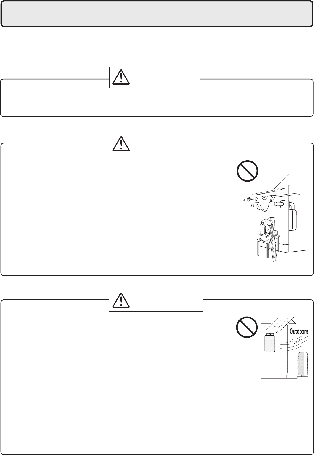
DANGER
Do Not Use Equipment for Purposes Other Than Those Specified
r%POPUVTFGPSPUIFSUIBOJODSFBTJOHUIFUFNQFSBUVSFPGUIFXBUFSTVQQMZBTVOFYQFDUFEBDDJEFOUT
may occur as a result.
Check Water Supply Quality
r*GUIFXBUFSTVQQMZJTJOFYDFTTPGHSBJOTQFSHBMMPONH-PGIBSEOFTTBDJEJDPSPUIFSXJTF
impure, treat the water with approved methods in order to ensure full warranty coverage.
WARNING
CAUTION
Check the Gas
r$IFDLUIBUUIFSBUJOHQMBUFJOEJDBUFTUIF
correct type of gas.
r$IFDLUIBUUIFHBTTVQQMZMJOFJTTJ[FEGPS
199,900 Btuh.
Check the Power
r5IFQPXFSTVQQMZSFRVJSFEJT7"$BU)[
6TJOHUIFJODPSSFDUWPMUBHFNBZSFTVMUJOàSFPSFMFDUSJDTIPDL
Use Extreme Caution if Using With a Solar Pre-Heater
r6TJOHUIJTVOJUXJUIBTPMBSQSFIFBUFSDBOMFBEUPVOQSFEJDUBCMFPVUQVUUFNQFSBUVSFTBOE
possibly scalding. If absolutely necessary, use mixing valves to ensure output temperatures do
OPUHFUUPTDBMEJOHMFWFMT%POPUVTFBTPMBSQSFIFBUFSXJUIUIFRVJDLDPOOFDUNVMUJTZTUFN
Precautions on Vent Pipe Replacement
r5IFWFOUTZTUFNXJMMBMNPTUDFSUBJOMZOFFEUPCFSFQMBDFEXIFOUIJTBQQMJBODFJTCFJOHJOTUBMMFE
0OMZVTFWFOUNBUFSJBMTUIBUBSFTQFDJàFEJOUIJT*OTUBMMBUJPO.BOVBMGPSVTFPOUIJTBQQMJBODF3FGFS
UPUIF7FOU1JQF*OTUBMMBUJPOTFDUJPOGPSEFUBJMT*G17$$17$PS$BUFHPSZ*7MJTUFEQJQFJTBMSFBEZ
JOTUBMMFEDIFDLGPSQVODUVSFTDSBDLTPSCMPDLBHFTBOEDPOTVMUXJUIUIFWFOUQJQFNBOVGBDUVSFS
before reusing.
*NQSPQFSWFOUJOHNBZSFTVMUJOàSFTQSPQFSUZEBNBHFPSFYQPTVSFUP$BSCPO.POPYJEF
Snow Precaution
r*GUIJTQSPEVDUXJMMCFJOTUBMMFEJOBOBSFBXIFSFTOPXJTLOPXOUPBDDVNVMBUFQSPUFDUUIFWFOU
UFSNJOBUJPOGSPNCMPDLBHFCZTOPXESJGUTPSEBNBHFGSPNTOPXGBMMJOHPGGPGSPPGT
5. Choosing Installation Site
-PDBUFUIFBQQMJBODFJOBOBSFBXIFSFMFBLBHFGSPNUIFVOJUPSDPOOFDUJPOTXJMMOPUSFTVMUJOEBNBHF
to the area adjacent to the appliance or to the lower oors of the structure. When such locations
cannot be avoided, it is recommended that a suitable drain pan, adequately drained, be installed
under the appliance. The pan must not restrict combustion air ow.
rLocate the vent terminal so that there are no obstacles around the termination and so that exhaust
can't accumulate. Do not enclose the termination with corrugated metal or other materials.
r"WPJEQMBDFTXIFSFàSFTBSFDPNNPOTVDIBTUIPTFXIFSFHBTPMJOF
benzene and adhesives are handled, or places in which corrosive gases
(ammonia, chlorine, sulfur, ethylene compounds, acids) are present.
6TJOHUIFJODPSSFDUWPMUBHFNBZSFTVMUJOàSFPSDSBDLJOH
r"WPJEJOTUBMMBUJPOJOQMBDFTXIFSFEVTUPSEFCSJTXJMMBDDVNVMBUF
%VTUNBZCMPDLUIFBJSTVQQMZPQFOJOHDBVTJOHUIFQFSGPSNBODFPGUIF
device fan to drop and incomplete combustion to occur as a result.
r"WPJEJOTUBMMBUJPOJOQMBDFTXIFSFTQFDJBMDIFNJDBMBHFOUT
(e.g., hair spray or spray detergent) are used.
Ignition failures and malfunction may occur as a result.
r$BSCPO.POPYJEF1PJTPOJOH)B[BSE%POPUJOTUBMMUIJTXBUFSIFBUFSJOB
mobile home, recreational vehicle or on a boat.
r5IFXBUFSIFBUFSJTEFTJHOFEGPSJOEPPSJOTUBMMBUJPOPOMZ/FWFSJOTUBMMJU
outdoors or in a bathroom, it may be damaged or a re may be caused.
r$POTVMUXJUIUIFDVTUPNFSDPODFSOJOHUIFMPDBUJPOPGJOTUBMMBUJPO
rInstall the water heater in an area that allows for the proper clearances
to combustible and noncombustible construction. Consult the rating
plate on the appliance for proper clearances.
r%POPUJOTUBMMUIFXBUFSIFBUFSJOBQMBDFXIFSFJUNBZCFUISFBUFOFECZ
falling objects, such as under shelves.
r5IFXBUFSIFBUFSNVTUCFJOTUBMMFEJOBQMBDFXIFSFTVQQMZBOEFYIBVTU
pipes can be installed as directed.
r%POPUJOTUBMMUIFXBUFSIFBUFSXIFSFUIFFYIBVTUXJMMCMPXPOPVUFS
walls or material not resistant to heat. Also consider the surrounding
trees and animals.
The heat and moisture from the water heater may cause discoloration
of walls and resinous materials, or corrosion of aluminum materials.
DANGER
WARNING
CAUTION
Prohibited
Prohibited
6
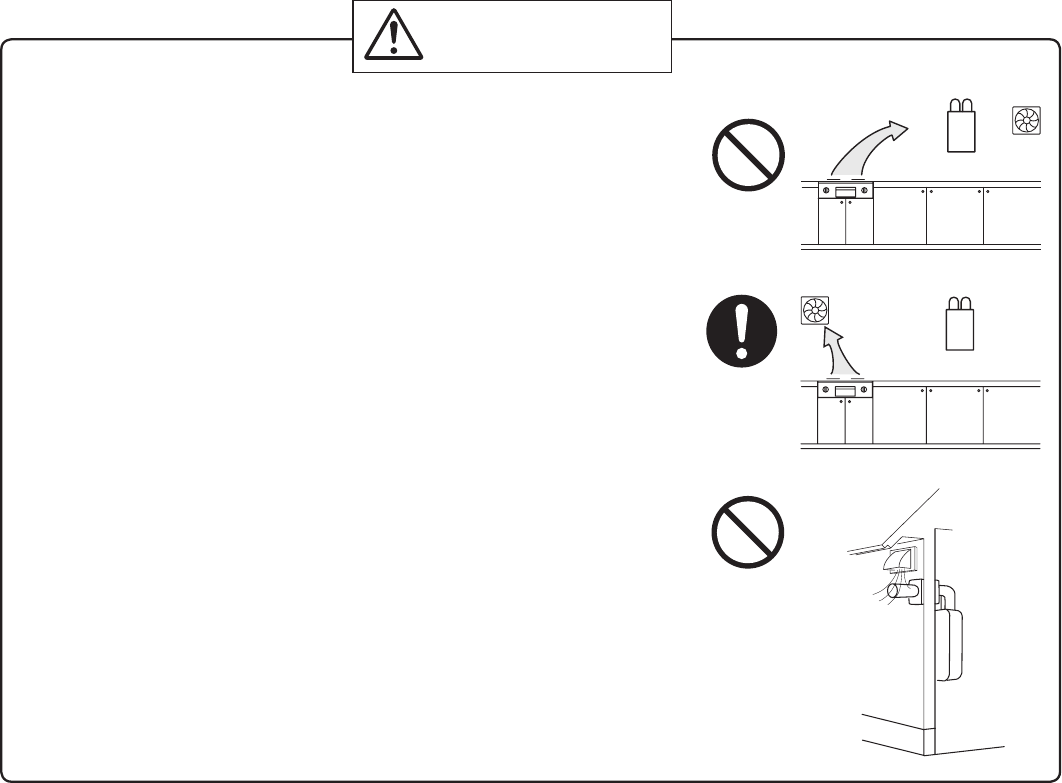
r"WPJEJOTUBMMBUJPOBCPWFHBTSBOHFTPSTUPWFT
r"WPJEJOTUBMMBUJPOCFUXFFOUIFLJUDIFOGBOBOETUPWF*GPJMZ
fumes or a large amount of steam are present in the installation
MPDBUJPOUBLFNFBTVSFTUPQSFWFOUUIFGVNFTBOETUFBNGSPN
entering in the equipment.
r*OTUBMMJOBMPDBUJPOXIFSFUIFFYIBVTUHBTáPXXJMMOPUCF
affected by fans or range hoods.
r5BLFDBSFUIBUOPJTFBOEFYIBVTUHBTXJMMOPUBGGFDUOFJHICPST
"WPJEJOTUBMMBUJPOPODPNNPOXBMMTBTUIFVOJUXJMMNBLFTPNF
operational noises while it is running.
r#FGPSFJOTUBMMJOHNBLFTVSFUIBUUIFFYIBVTUáVFUFSNJOBUJPOXJMM
IBWFUIFQSPQFSDMFBSBODFTBDDPSEJOHUPUIF/BUJPOBM'VFM(BT
$PEF"/4*;
Be sure to do
Prohibited
Prohibited
CAUTION
State of California: The water heater must be braced, anchored or strapped to avoid moving during
BOFBSUIRVBLF$POUBDUMPDBMVUJMJUJFTGPSDPEFSFRVJSFNFOUTJOZPVSBSFBPSDBMM&MFDUSPMVY)PNF
1SPEVDUT*ODBUBOESFRVFTUJOTUSVDUJPOT
5IF$PNNPOXFBMUIPG.BTTBDIVTFUUT5IFXBUFSIFBUFSDBOCFVTFEGPSIPUXBUFSPOMZBOEOPUJOB
combination of domestic and space heating.
'PS7FOUJOH.BOVGBDUVSFST3FRVJSFNFOUTDBMM&MFDUSPMVY)PNF1SPEVDUT*ODBUPS
visit us at www. electroluxappliances. com.

6. Installation Clearances
#FGPSFJOTUBMMJOHDIFDLGPSUIFGPMMPXJOH
Install in accordance with relevant building and mechanical codes, as well as any local, state or
OBUJPOBMSFHVMBUJPOTPSJOUIF BCTFODF PG MPDBMBOETUBUFDPEFTUPUIF /BUJPOBM 'VFM(BT$PEF
"/4*;/'1"mMBUFTUFEJUJPO
WARNING
Item
Distance from combustibles
r.BJOUBJOUIFGPMMPXJOHDMFBSBODFT
from both combustible and
OPODPNCVTUJCMFNBUFSJBMT
$IFDL Illustration
r*GQPTTJCMFMFBWFNNPSNPSFPO
either side of the unit to facilitate inspection.
r*GQPTTJCMFMFBWFNNPSNPSFJO
front of the unit to facilitate maintenance
and service if necessary.
r*G QPTTJCMF MFBWF NN PS NPSF
above and below the vent pipe to facilitate
inspection and repair if necessary.
Securing of space for
repair/inspection
NN
or more
Distance from
the side
NN
or more
NN
or more
NN
or more
NNPSNPSF
NNPSNPSF
NN
or more
NN
or more
<When using indoor air for combustion>
r*GUIFVOJUXJMMCFJOTUBMMFEJOUIFWJDJOJUZPG
BQFSNBOFOULJUDIFOSBOHFPSTUPWFUIBU
has the possibility of generating steam
that contains fats or oils, use a *dividing
plate or other measure to ensure that the
unit is not exposed to air containing such
impurities.
* The dividing plate should be of
noncombustible material of a width
greater than the water heater.
Exhaust hood
Range
Dividing plate Water
heater
$PPLJOH&RVJQNFOU
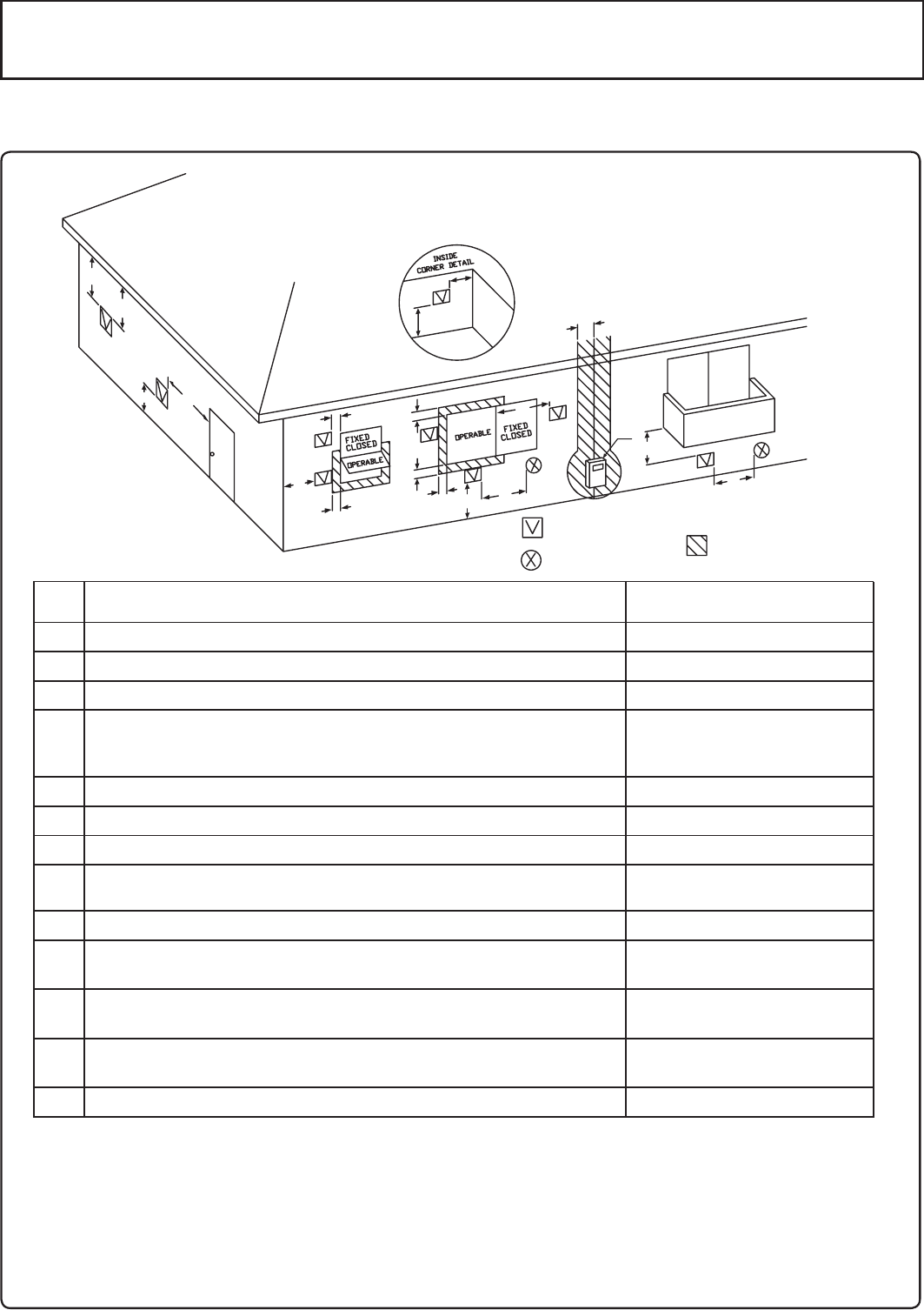
DescriptionRef
A=
Clearance above grade, veranda, porch, deck, or balcony
B=
Clearance to window or door that may be opened
C=
Clearance to permanently closed window
D=
Vertical clearance to ventilated soffit located above the
terminal within a horizontal distance of 2 feet (61 cm)
from the center line of the terminal
E=
Clearance to unventilated soffit
F=
Clearance to outside corner
G=
Clearance to inside corner
H=
Clearance to each side of center line extended above
meter/regulator assembly
I=
Clearance to service regulator vent outlet
J=
Clearance to nonmechanical air supply inlet to building or
the combustion air inlet to any other appliance
K=
Clearance to a mechanical air supply inlet
L=
Clearance above paved sidewalk or paved driveway located
on public property
Clearance under veranda, porch, deck, or balcony
M=
1
In accordance with the current ANSI Z223.1 / NFPA 54 National Fuel Gas Code
* Clearance in accordance with local installation codes and the requirements of the gas supplier
.
bClearance to opposite wall is 24 inches (60 cm).
12 in (30 cm)
*
*
*
*
*
*
*
*
3 ft (91 cm) above if within
10 ft (3 m) horizontally
*
12 in (30 cm)
12 in (30 cm)
US Direct Vent Installations 1
Vent Terminal
D
E
B
B
F
B
A
G
H
I
CB
M
K
J
B
B
L
Air Supply Inlet
Area Where Termina
l
is Not Permitted
A
Clearance Requirements from Vent Terminations to Building Openings
<When supplying combustion air from the outdoors (Direct Vent)>
"MMDMFBSBODFSFRVJSFNFOUTBSFJOBDDPSEBODFXJUI"/4*;BOEUIF/BUJPOBM'VFM(BT$PEF
"/4*;

9
DescriptionRef
A=
Clearance above grade, veranda, porch, deck, or balcony
B=
Clearance to window or door that may be opened
C=
Clearance to permanently closed window
D=
Vertical clearance to ventilated soffit located above the
terminal within a horizontal distance of 2 feet (61 cm)
from the center line of the terminal
E=
Clearance to unventilated soffit
F=
Clearance to outside corner
G=
Clearance to inside corner
H=
Clearance to each side of center line extended above
meter/regulator assembly
I=
Clearance to service regulator vent outlet
J=
Clearance to nonmechanical air supply inlet to building or
the combustion air inlet to any other appliance
K=
Clearance to a mechanical air supply inlet
L=
Clearance above paved sidewalk or paved driveway located
on public property
Clearance under veranda, porch, deck, or balcony
M=
1
In accordance with the current ANSI Z223.1 / NFPA 54 National Fuel Gas Code
* Clearance in accordance with local installation codes and the requirements of the gas supplier
.
bClearance to opposite wall is 24 inches (60 cm).
*
*
*
*
*
*
*
*
3 ft (91 cm) above if within
10 ft (3 m) horizontally
*
12 in (30 cm)
US Non-Direct Vent Installations 2
Vent Terminal
D
E
B
B
F
B
A
G
H
I
CB
M
K
J
B
B
L
Air Supply Inlet
Area Where Termina
l
is Not Permitted
A
4 ft (1.2 m) below or to side of opening;
1 ft (30 cm) above opening
4 ft (1.2 m) below or to side of opening;
1 ft (30 cm) above opening
Clearance Requirements from Vent Terminations to Building Openings
<When supplying combustion air from the indoors (Non-Direct Vent)>
"MMDMFBSBODFSFRVJSFNFOUTBSFJOBDDPSEBODFXJUI"/4*;BOEUIF/BUJPOBM'VFM(BT$PEF
"/4*;
10
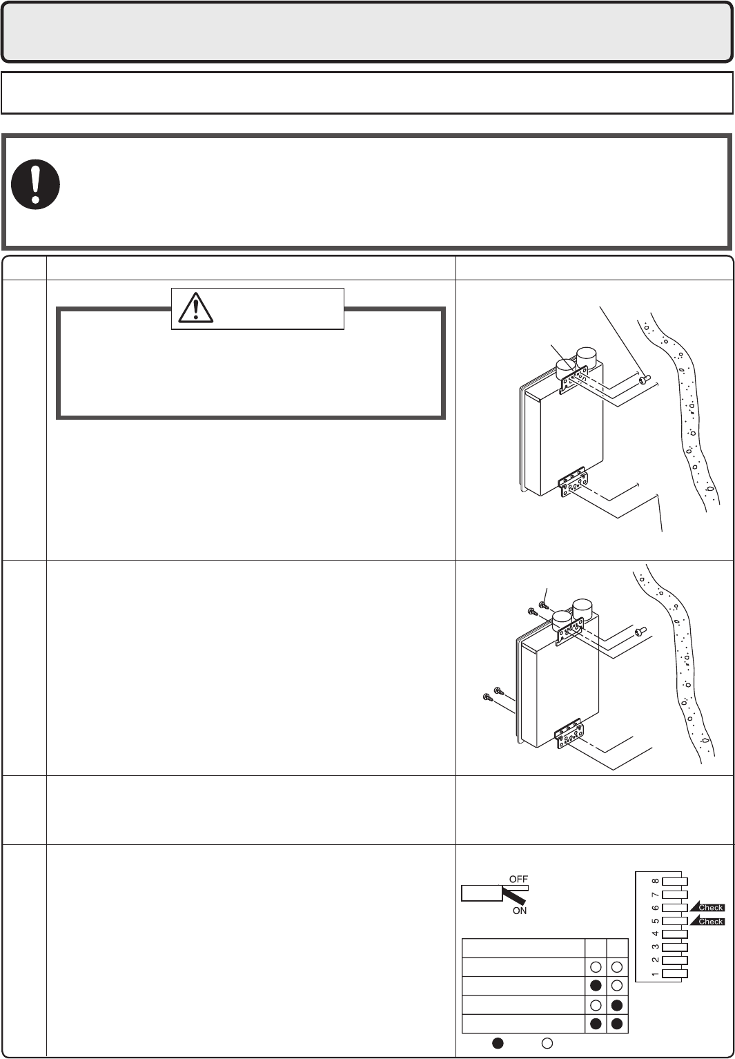
7. Installation
Securing to the wall
Illustration
$IFDL
%SJMMIPMFTGPSUIFSFNBJOJOHGPVSTDSFXT
)BOHUIFVOJUBHBJOCZUIFàSTUTDSFXBOEUIFO
insert and tighten the remaining four screws.
5BLFXBUFSQSPPàOHNFBTVSFTTPUIBUXBUFSEPFT
not enter the building from screws mounting the
device.
r.BLFTVSFUIFVOJUJTJOTUBMMFETFDVSFMZTPUIBUJUXJMM
OPUGBMMPSNPWFEVFUPWJCSBUJPOTPSFBSUIRVBLFT
%SJMMBTJOHMFTDSFXIPMFNBLJOHTVSFUPIJUBTUVE
*OTFSUBOEUJHIUFOUIFTDSFXBOEIBOHUIFVOJUCZ
UIFVQQFSXBMMNPVOUJOHCSBDLFU
3. Determine the positions for the remaining four screws
UXPGPSUIFUPQCSBDLFUBOEUXPGPSUIFCPUUPNBOE
remove the unit.
r5IFXFJHIUPGUIFEFWJDFXJMMCFBQQMJFEUPUIFXBMM*GUIFTUSFOHUIPGUIFXBMMJTOPU
sufcient, reinforcement must be done to prevent the transfer of vibration.
r%POPUESPQPSBQQMZVOOFDFTTBSZGPSDFUPUIFEFWJDFXIFOJOTUBMMJOH*OUFSOBMQBSUTNBZ
be damaged and may become highly dangerous.
r*OTUBMMUIFVOJUPOBWFSUJDBMXBMMBOEFOTVSFUIBUJUJTMFWFM
-PDBUJOH4DSFX)PMFT
.PVOUJOH
Structure
r8IFOJOTUBMMJOHXJUICBSFIBOETUBLFDBVUJPOUP
not inict injury.
r#FDBSFGVMOPUUPIJUFMFDUSJDBMXJSJOHHBTPSXBUFS
piping while drilling holes.
Item
CAUTION
Be sure to do
.PVOUJOH#SBDLFU
(upper)
-PDBUJPOPG4DSFX)PMF
-PDBUJOH4DSFX)PMFT
Installations at Elevations
"CPWFGU
r"EKVTUUIF EJQTXJUDIFTBT JMMVTUSBUFEJOUIF UBCMFUP
the right if this water heater is installed at an altitude
PGGUNPSIJHIFS
r%JTDPOOFDU QPXFS UP UIF XBUFS IFBUFS CFGPSF
DIBOHJOH UIF EJQ TXJUDIFT 'BJMVSF UP QFSGPSN UIJT
TUFQ XJMM SFTVMU JO B DPEF EJTQMBZFE PO UIF
remote controller and a cease in operation. If this
occurs, disconnect, then reconnect power to the
water heater to reset the system.
Note : Please refer to page 31 for the location of the
EJQTXJUDICBOL
Anchoring Screw
* Do not change any other dipswitches.
* High elevation adjustment.
65
2,001 - 4,000 ft (611 - 1,220m)
0 - 2,000 ft (0 - 610m)
ON= OFF=
4,001 - 6,000 ft (1,221 - 1,830m)
6,001 - 8,000 ft (1,831 - 2,440m)

11
Filling the condensate trap with water
The condensate trap can be lled before connecting the vent pipe.
Filling the condensate trap before vent pipe installation.
DANGER
1SJPSUPJOJUJBMTUBSUVQNBLFTVSFUIBUZPVàMMUIFDPOEFOTBUFUSBQXJUIXBUFS
This is to prevent dangerous exhaust gases from entering the building.
'BJMVSFUPàMMUIFDPOEFOTBUFUSBQDPVMESFTVMUJOTFWFSFQFSTPOBMJOKVSZPSEFBUI
Please follow one of the procedures described below to ensure that the condensate trap is lled with water.
'JMMUIFDPOEFOTBUFUSBQCZQPVSJOHBQQSPYP[NMPGXBUFSJOUPUIFFYIBVTUBDDFTTPSZPOUIFUPQ
of the appliance as illustrated below.
Or, if the vent pipe has already been installed:
"GUFSJOTUBMMJOHUIFESBJOQJQFNBLFTVSFUIBUUIFBSFBBSPVOEUIFBQQMJBODFJTXFMMWFOUJMBUFEPQFOB
window or a door if necessary.
Then, operate the unit and verify that condensate is coming out of the drain pipe.
(During normal use of the water heater, condensate will begin to discharge from the drain pipe within
NJOVUFTPGVTF)PXFWFSEFQFOEJOHPOUIFTFBTPOBOEPSJOTUBMMBUJPOTJUFDPOEJUJPOTJUNBZUBLFMPOHFS
/PUF5IFDPOEFOTBUFEJTDIBSHFEGSPNUIFXBUFSIFBUFSIBTBQ)MFWFMPGBQQSPYJNBUFMZ
If required by local code, the condensate must be neutralized prior to disposal into the sewer
system.
3FGFSUPQBHFTGPSBEEJUJPOBMEFUBJMT
30 oz.
850ml
*OUBLF
Exhaust
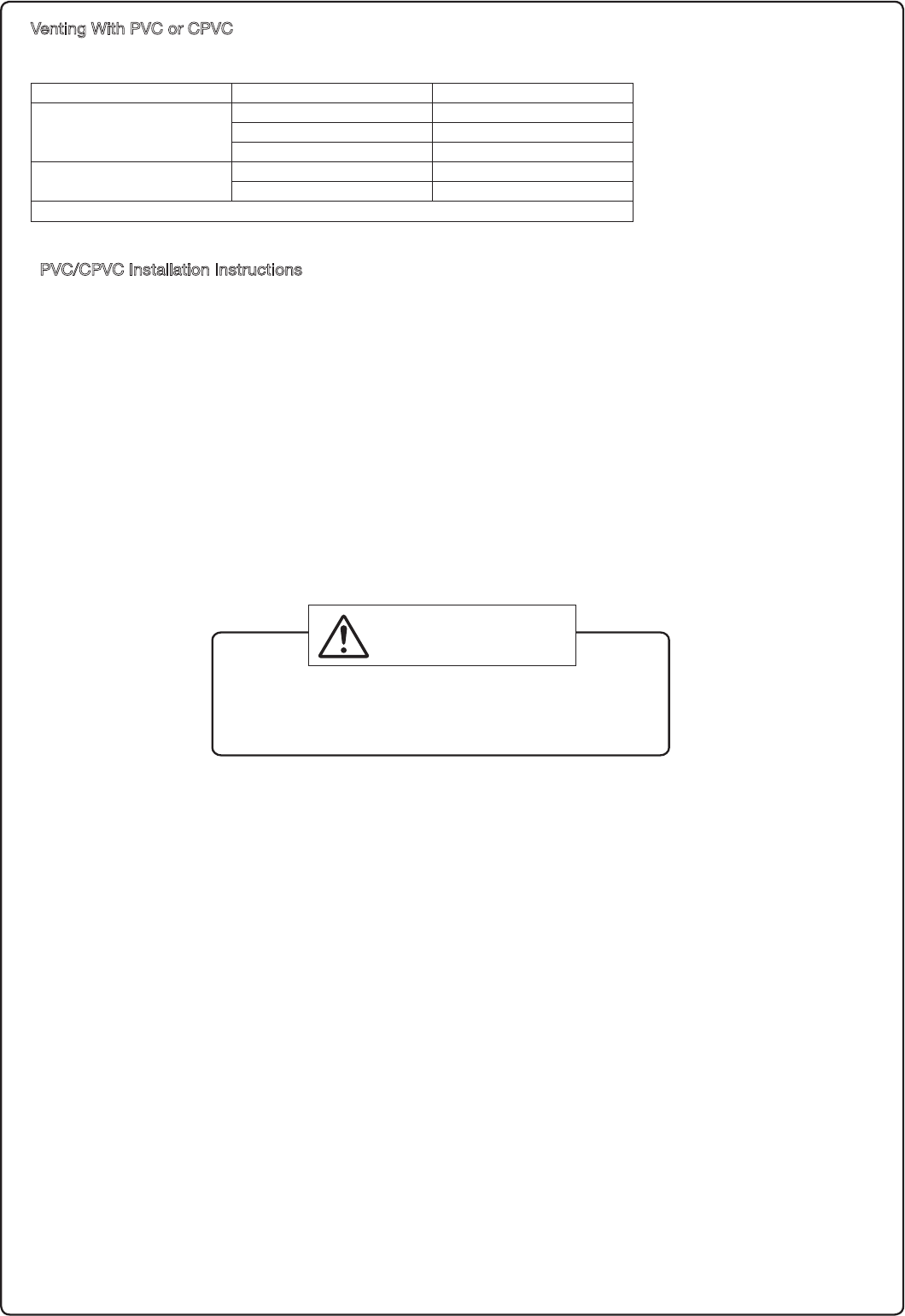
Maximum Vent Lengths
rThis appliance has been designed to be vented
XJUI FJUIFS NN PS NN 17$ PS
$17$QJQF
Do not exceed the following maximum vent lengths:
* Not including the termination
Refer to page 16 for max. vent lengths
XIFOVTJOHUFSNJOBUJPO58))03$0/$
r.BJOUBJOUIFTBNFWFOUQJQFEJBNFUFSGSPNUIF
heater ue to the vent termination. The exhaust
BOE JOUBLF QJQFT NVTU CF UIF TBNF WFOU QJQF
diameter.
8. Vent Pipe Installation
WARNING
Be sure to do
$"3#0/.0/09*%&10*40/*/(
'PMMPXBMMWFOUTZTUFNSFRVJSFNFOUTJOBDDPSEBODFXJUISFMFWBOUMPDBMPSTUBUFSFHVMBUJPO
PSJOUIFBCTFODFPGMPDBMPSTUBUFDPEFJOUIF64UPUIF/BUJPOBM'VFM(BT$PEF"/4*
;/'1"mMBUFTUFEJUJPO
No. of Elbows
.BY4USBJHIU7FOU-FOHUI
/" hN
hN hN
hN hN
hN hN
Pipe diameter NN NN
r6OEFS OPSNBM DPOEJUJPOT UIJT BQQMJBODF XJMM
not produce an exhaust flue temperature
JO FYDFTT PG ' $ BOE TDIFEVMF
17$QJQFNBZCFVTFEBTUIFWFOUNBUFSJBM
*GSFRVJSFECZ MPDBM DPEFTDIFEVMFPS
$17$NBZBMTPCFVTFEPOUIJTBQQMJBODF
3FGFSUPQBHFGPSBEEJUJPOBMSFRVJSFNFOUT
r.BLF TVSF UIF WFOU TZTUFN JT HBT UJHIU BOE
XJMMOPUMFBL
r4VQQPSUUIFWFOUQJQFXJUIIBOHFSTBUSFHVMBS
intervals as specied by these instructions or
the instructions of the vent manufacturer.
r%P OPU DPNNPO WFOU PS DPOOFDU NPSF UIBO
one appliance to this venting system.
r
The total vent length including horizontal & vertical
vent runs should be no less than 3' (0.9m).
r%POPUTUPSFIB[BSEPVTPSáBNNBCMFTVCTUBODFT
OFBSUIFWFOUUFSNJOBUJPOBOEDIFDLUIBUUIF
UFSNJOBUJPOJTOPUCMPDLFEJOBOZXBZ
r4UFBN PS DPOEFOTFE XBUFS NBZ DPNF PVU
from the vent termination. Select the location
for the termination so as to prevent injury or
property damage.
r*GTOPXJTFYQFDUFEUPBDDVNVMBUFUBLFDBSF
the end of the pipe is not covered with snow
or hit by falling lumps of snow.
General Requirements
Clearances
17$PS$17$IBTCFFOBQQSPWFEGPSVTFPOUIJT
appliance with zero clearance to combustibles.
13
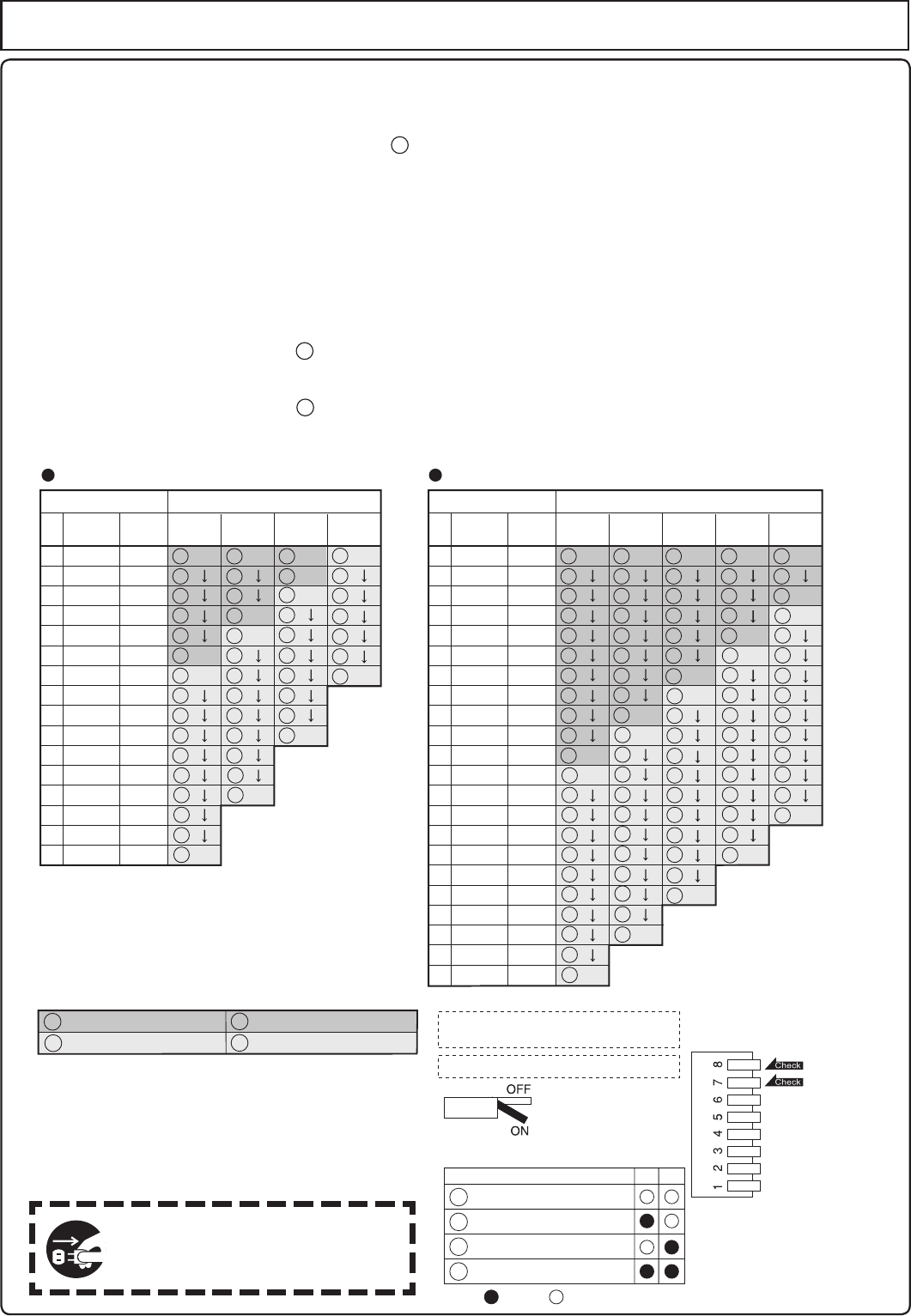
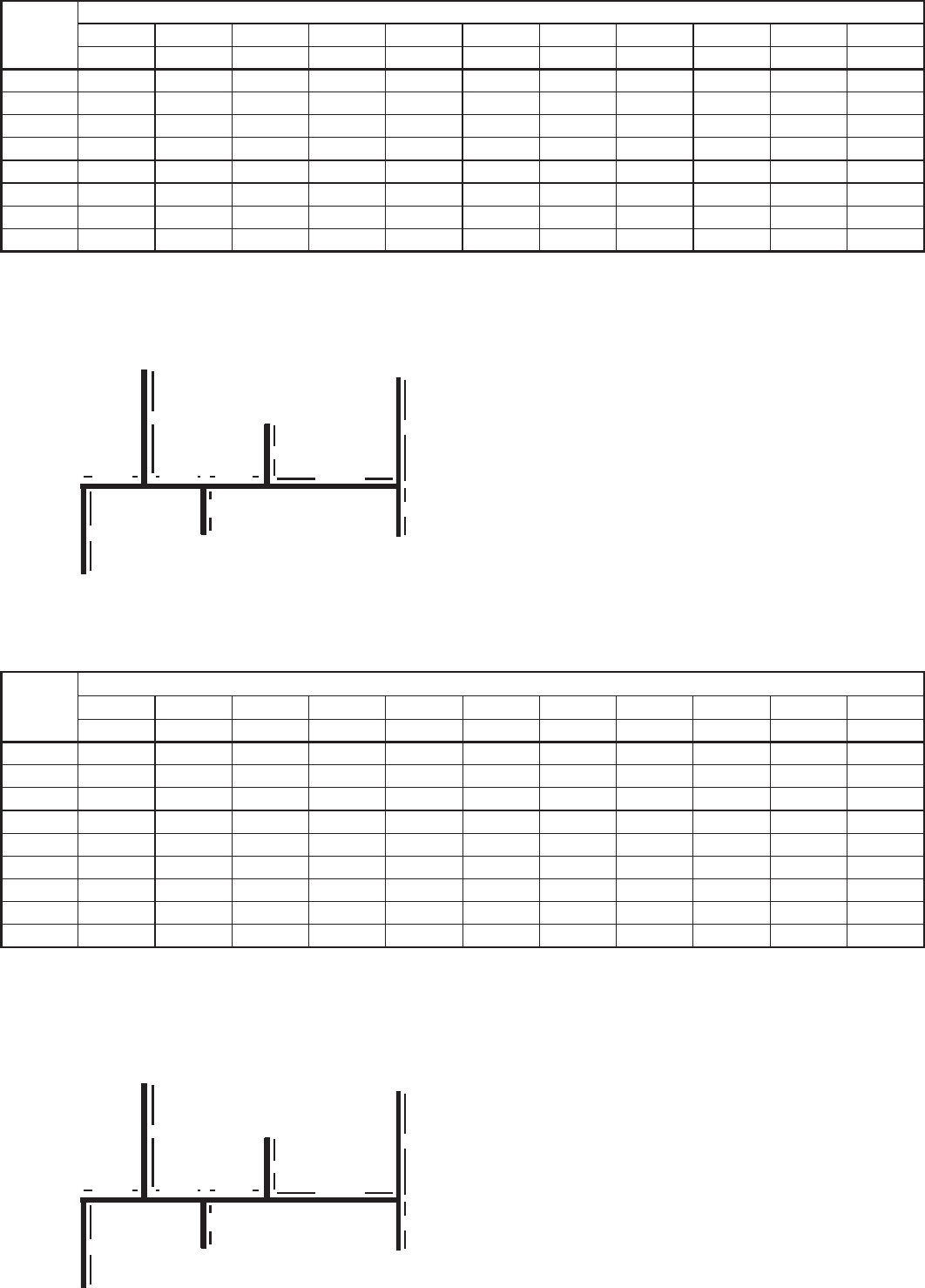
5IFVOJUDBOCFBEKVTUFEUPBDDPNNPEBUFMPOHFSWFOUSVOTSFGFSUPUIFCFMPXUBCMFUPàOEUIF
maximum vent length based on the number of elbows. Adjust the dip switches according to the vent
condition noted in the tables below.
Note:
#ZEFGBVMUUIFVOJUIBTCFFOTFUUPUIFTIPSUMFOHUIVTJOHNNQJQFDPOEJUJPO8IFOBEKVTUJOH
UIFEJQTXJUDIFTGPSMPOHFSWFOUSVOTUIF#56)JOQVUPGUIFBQQMJBODFXJMMCFSFEVDFECZVQUP
Maximum Vent Length Adjustment Dipswitches
5XP elbows, maximum length = 3 ft. (0.9m)
XJUIEJQTXJUDIFTTFUBUTIPSUMFOHUIVTJOHNNQJQFDPOEJUJPO
5XPFMCPXTNBYJNVNMFOHUIGUN
XJUIEJQTXJUDIFTTFUBUMPOHMFOHUIVTJOHNNQJQFDPOEJUJPO
<.BYJNVN7FOU-FOHUI&YBNQMF>
r%JTDPOOFDUQPXFSUPUIFXBUFSIFBUFSCFGPSFDIBOHJOHUIFEJQTXJUDIFT'BJMVSFUPQFSGPSN
UIJTTUFQXJMMSFTVMUJOBDPEFEJTQMBZFEPOUIFSFNPUFDPOUSPMMFSBOEBDFBTFJOPQFSBUJPO
.
If this occurs, disconnect, then reconnect power to the water heater to reset the system.
/PUF1MFBTFSFGFSUPQBHFGPSUIFMPDBUJPOPGUIFEJQTXJUDICBOL
0
3
6
9
12
15
18
21
24
27
30
33
36
39
42
45
48
51
54
57
60
63
0.00
0.90
1.80
2.70
3.60
4.50
5.40
6.30
7.20
8.10
9.00
9.90
10.80
11.70
12.60
13.50
14.40
15.30
16.20
17.10
18.00
18.90
m 10 2 3 4ft
Vent length* Elbows
0
1
2
3
4
5
6
7
8
9
10
11
12
13
14
15
16
17
18
19
20
21
Number of
pieces**
3
3
0%
-3%
-3%
-5%
3
3
3
3
3
3
3
3
3
4
4
4
4
4
4
4
4
4
4
4
3
3
0%
-3%
-3%
-5%
3
3
3
3
3
3
3
4
4
4
4
4
4
4
4
4
4
4
3
3
0%
-3%
-3%
-5%
3
3
3
3
3
4
4
4
4
4
4
4
4
4
4
4
3
3
0%
-3%
-3%
-5%
3
3
3
4
4
4
4
4
4
4
4
4
4
4
3
3
0%
-3%
-3%
-5%
3
4
4
4
4
4
4
4
4
4
4
4
0
3
6
9
12
15
16
18
21
22
24
27
28
30
33
34
0.00
0.90
1.80
2.70
3.60
4.50
4.80
5.40
6.30
6.60
7.20
8.10
8.40
9.00
9.90
10.20
m 10 2 3ft
Vent length*
3” Pipe
Elbows
0
1
2
3
4
5
6
6
7
8
8
9
10
10
11
12
Number of
pieces**
1
1
0%
0%
-5%
-5%
1
1
1
1
2
2
2
2
2
2
2
2
2
2
1
1
0%
0%
-5%
-5%
1
1
2
2
2
2
2
2
2
2
2
1
1
0%
0%
-5%
-5%
2
2
2
2
2
2
2
2
0%
-5%
2
2
2
2
2
2
2
13
24
Short length using 4" (100mm) pipe
Short length using 3" (75mm) pipe
Long length using 3" (75mm) pipe Long length using 4" (100mm) pipe
Short length using 4" (100mm) pipe
Short length using 3" (75mm) pipe
Long length using 3" (75mm) pipe
Long length using 4" (100mm) pipe
**Table assumes straight vent pieces are 3’ (0.9m) each.
Shorter or longer vent pieces may also be used up to the maximum
allowed vent length.
Do not change any other dipswitches.
Vent length condition.
1
7 8
ON= OFF=
2
3
4
4” Pipe
* Not including the termination.
* Not including the termination.
Refer to page 16 for max. vent lengths
when using termination TWHHORCONC.
.BYJNVN7FOU-FOHUIBOE3FEVDFE*OQVU$POàHVSBUJPOT
The power must be unplugged
when adjusting the dip switches
to switch the airow amount.
WARNING
! # " # !
!$!! "
:
C! ; , @
!1-; ,9.452
;+<; ,9/332
!1-; ,911.
, ; ,9/231
; ,9160
;,; !
E
E
E
E 9= F 0'(-6)>> $!! #
=>"!
E <= *>B ! "=#
!> !* >B ! =="7
A!#! >
"=!=>? F
? ! =#** :#
">!B ! =" =
E
E ;;=">! B D
=! =
! =>!#! : !>0'(-6) " !
B ! "
0%1%!5-#=! *B" 9:8! >
B=!=#! 2&
; < ;;
9=" B ! F =B =
E
E =! = " > # # >
" =# " =>
9 !B B ! =! #
< B *! !
7 :!
:#;;!1-!> B
B" !!
V
ertical Vent Termination- PVC/CPVC Materials Only
8
8
8
8
8
8
8
8
8
Horizontal Vent Termination- PVC/CPVC Materials Only
8
8
8
8
8
8
8
8
Hanger
Straps
**1' mini
* Not supplied with water heater,
order separately.
mum recommended,
but not required.
3 ft. Min.
FirestopFirestop
Firestop/Support
Roof
Flashing
Roof
Flashing
Hanger
Strap
**1'
Minimum
**1'
Minimum
Support
"256,
"256,<,4:
$6=(8+9
Intake
Exhaust
<,4:
$6=(8+9
Intake Exhaust
5<,83(>03;3
945=2,<,2
58=/0*/,<,8
09.8,(:,8
5<,83(>03;3
945=2,<,2
58=/0*/,<,8
09.8,(:,8
49,8:08+
"*8,,404
4+5-
2)5=
":583
522(8
":583
522(8
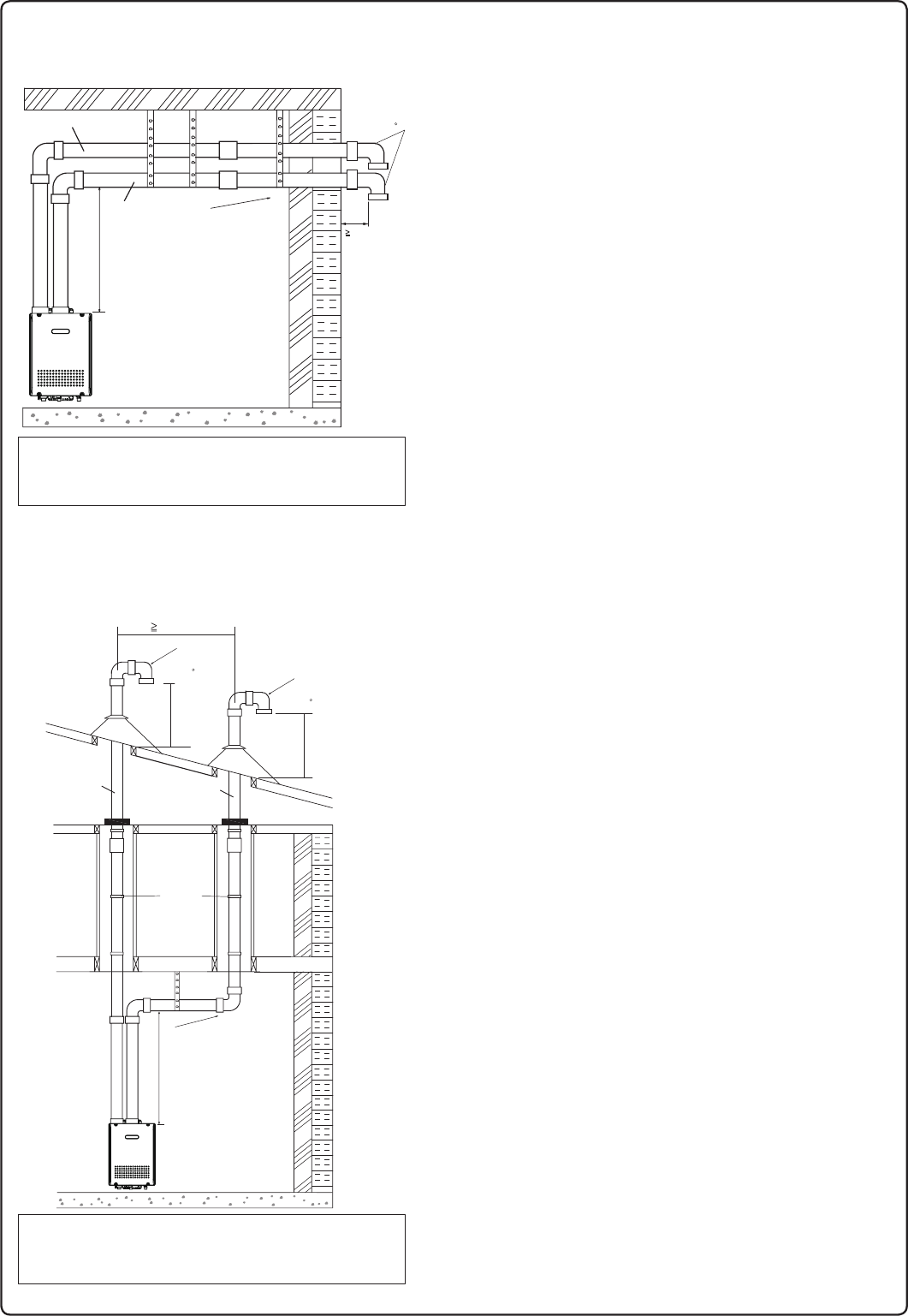
As illustrated on the left, make sure to keep a distance of 3' (0.9m)
or wider between the intake and exhaust when installing the vent piping.
*
If 3’ (0.9m) distance between Intake and Exhaust cannot be ensured,
the installation can be carried out only in the installation method shown in page 17.
T/,#&!:,8304(:0543(?),;9,+0462(*,5-,2)5=9(9
:/,/580@54:(2<,4::,8304(:0549:0945:4,*,99(8?:5;9,)08+9*8,,49
=0:/:/,#&!:,8304(:054",,6(.,-58358,04-5
#,8304(:,(:2,(9:33()5<,.8(+,58()5<,945=204,
#,8304(:,(:2,(9:A3()5<,(6;)20*=(21=(?A3
-853:/,*53);9:054(0804:(1,5-(4?(6620(4*,(4+A3
-853(4?5:/,8);02+04.56,404..(9;:020:?3,:,89,8<0*,8,.;2(:58,:*
#,8304(:,(:2,(9:A3()5<,(4?-58*,+(08042,:=0:/04
A3A3),25=A3/580@54:(22?-85358A3
()5<,(4?+558=04+5=58.8(<0:?(08042,:04:5(4?);02+04.6,8
(:054(2;,2(95+,"'
"256,:/,/580@54:(2<,4:;6=(8+9-58,<,8?33
:5=(8+:/,:,8304(:054
$9,(*54+,49(:054+8(040-4,*,99(8?
4:/,53354=,(2:/5-(99(*/;9,::9(*(8)543545>0+,+,:,*:58
098,7;08,+-58(2290+,=(22/580@54:(22?<,4:,+.(9-;,2,7;063,4:
2,(9,8,-,8:5#,*/40*(2;22,:04#-58-;22049:(22(:054
049:8;*:0549
9022;9:8(:,+54:/,2,-:3(1,9;8,:51,,6(+09:(4*,
5-A358=0+,8),:=,,4:/,04:(1,(4+,>/(;9:
=/,4049:(2204.:/,<,4:60604.
T/,#&%!# :,8304(:0543(?),;9,+0462(*,5-
,2)5=9(9:/,
<,8:0*(2<,4::,8304(:054:0945:4,*,99(8?
:5;9,)08+9*8,,49
=0:/:/,#&%!# :,8304(:054
#,8304(:,(:2,(9:A3-853:/,*53);9:054(08
04:(1,5-(4?(6620(4*,(4+A3-853(4?5:/,8
);02+04.56,404..(9;:020:?3,:,89,8<0*,8,.;2(:58,:*
4*259,,>:,8058<,4:9?9:,39),25=:/,855-204,:52030:
*54+,49(:054(4+685:,*:(.(049:3,*/(40*(2-(02;8,
&/,4:/,<,4:6,4,:8(:,9(D55858*,0204.(4+0945:
8;4404.04(E8,8(:,+9/(-:(E8,9:56(4+9;6658:09
8,7;08,+
&/,4:/,<,4::,8304(:0540925*(:,+45:2,99:/(4
A3-853(<,8:0*(2=(225890302(85)9:8;*:054
:,8304(:,()5<,:/,855-(:2,(9:A3);:45:
358,:/(4A304(**58+(4*,=0:/:/,(:054(2
;,2(95+,"'
85<0+,<,8:0*(29;6658:,<,8?A358(98,7;08,+
)?:/,<,4:606,3(4;-(*:;8,8A9049:8;*:0549
9/58:/580@54:(29,*:054098,*533,4+,+:568,<,4:
+,)809-853-(2204.04:5:/,=(:,8/,(:,8
&/,4;904.(/580@54:(29,*:0549256,:/,/580@54:(2
<,4:B;6=(8+9-58,<,8?B33:5=(8+:/,
:,8304(:054:5+8(04*54+,49(:,
A30403;38,*533,4+,+
);:45:8,7;08,+
5:9;6620,+=0:/=(:,8/,(:,8
58+,89,6(8(:,2?
&/,4*/55904.04:(1,(4+,>/(;9::,8304(:0549?5;3;9:;9,:/,
9(3,:?6,5-,2)5=0,)5:/C,2)5=9
#/09=022/,26=0:/6856,8*53);9:054)?6;::04.)5:/:,8304(:054904
:/,9(3,68,99;8,@54,
&/,4*/55904.04:(1,(4+,>/(;9::,8304(:0549?5;3;9:;9,:/,
9(3,:?6,5-,2)5=0,)5:/C,2)5=9
#/09=022/,26=0:/6856,8*53);9:054)?6;::04.)5:/:,8304(:054904
:/,9(3,68,99;8,@54,
49,8:08+
"*8,,404
4+5-
2)5=
49,8:08+"*8,,4
044+5-2)5=
B04
Vent Pipe Installation
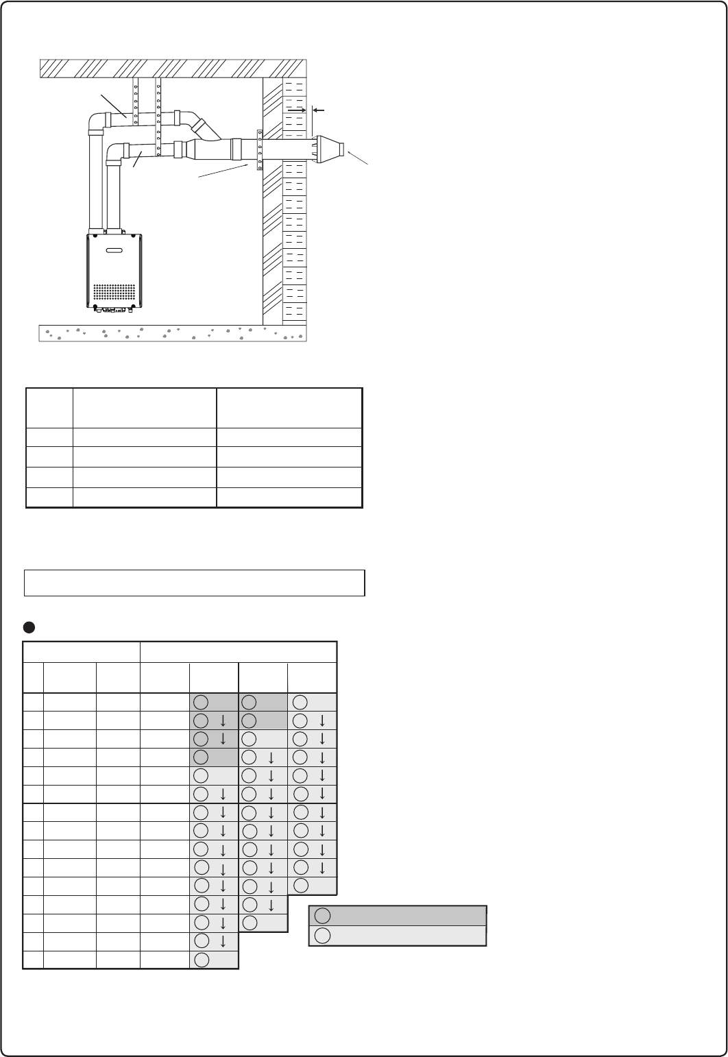
16
No. of
Elbows
3
2
1
4
Max. Straight Vent Length**
3" (75mm) PVC or CPVC
Max. Straight Vent Length**
4" (100mm) PVC or CPVC
** Not including the concentric termination
16' (4.8m)
N / A
22' (6.6m)
28' (8.4m)
30' (9.0m)
N / A
36' (10.8m)
42' (12.6m)
Maximum Vent Length Adjustment Dip switches.
0
3
6
9
12
15
18
21
24
27
30
33
36
39
42
0.00
0.90
1.80
2.70
3.60
4.50
5.40
6.30
7.20
8.10
9.00
9.90
10.80
11.70
12.60
m 10 2 3ft
Vent length*** Elbows
0
1
2
3
4
5
6
7
8
9
10
11
12
13
14
N /A
N /A
N /A
N /A
N /A
N /A
N /A
N /A
N /A
N /A
N /A
N /A
N /A
N /A
N /A
Number of
pieces****
-5%
-5%
3
3
0%
3
3
4
4
4
4
4
4
4
4
4
4
4
3
3
0%
4
4
4
4
4
4
4
4
4
4
4
4
4
-3%
-3%
-3%
-3%
-3%
-5%
4
4
4
4
4
4
4
4
4
4” Pipe
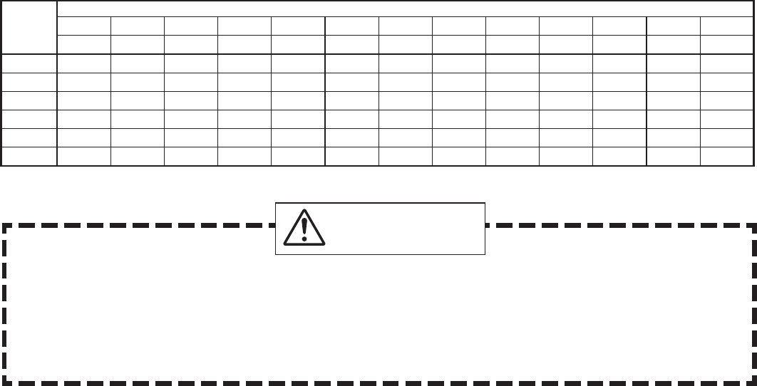
<Maximum Vent Length and Reduced Input Congurations>
*** Refer to page 13 for 3" pipe Maximum Vent Length Adjustment Dipswitches table.
3
4
Short length using 4" (100mm) pipe
Long length using 4" (100mm) pipe
****Table assumes straight vent pieces are 3’ (0.9m) each.
Shorter or longer vent pieces may also be used up to the maximum
allowed vent length.
H
H
H
H
H
H
H
Hanger
Straps
3" (75mm) or
4" (100mm)
Intake*
Horizontal Vent Termination- 3" (75m) Concentric PVC/CPVC Termination
3" (75m
m
) or
4" (100m
m
)
Exhaust*
The concentric termination TWHHORCONC may be
shortened, but not lengthened from its original
factory supplied length.
The concentric termination may only be used
for horizontal terminations.
Terminate at least 12" (300mm) above grade or
above snow line.
Terminate at least 7' (2.1m) above a public walkway,
6' (1.8m) from the combustion air intake of any
appliance, and 3' (0.9m) from any other building
opening, gas utility meter, service regulator etc.
Terminate at least 3' (0.9m) above any forced air
inlet within 10' (3m), 1' (0.3m) below, 1' (0.3m)
horizontally from or 1' (0.3m) above any door,
window, or gravity air inlet into any building per
National Fuel Gas Code ANSI Z223.1/NFPA 54.
Slope the horizontal vent 1/4" upwards for every
12" (300mm).
Use a condensation drain if necessary.
In the Commonwealth of Massachusetts a carbon
monoxide detector is required for all side wall
horizontally vented gas fuel equipment.
Please refer to Technical Bulletin TB 010606 for full
installation instructions.
Slope vent
Upwards
* 4" (100mm) pipe requires the use of a reducing coupling
just prior to the termination.
H
H
H
H
3" (75mm) or 4" (100mm) PVC or CPVC pipe
may be used with the concentric termination.
Maintain the same vent pipe diameter from the
water heater ue to the termination.
Do not exceed the maximum vent lengths as
specied in this section.
When using 4" (100mm) pipe, it will be necessary
to use 4" (100mm) x 3" (75mm) reducing couplings
and a short section of 3" (75mm) pipe to connect to
the termination.
Use no more than a 6" (150mm) section of pipe to
make the connection between the reducing
couplings and the termination.
H
Install a securing strap to prevent movement of
the termination.
There must be a 1" (25mm) to 4" (100mm) clearance
between the outside wall and the air intake section
of the termination as illustrated on the left.
1" (25mm) to
4" (100mm)
Insert Bird Screen ***
in End of Termination
*** Not supplied with
water heater,
order separately.
Strap
Vent Pipe Installation
Horizontal Vent Termination- PVC/CPVC Materials Only
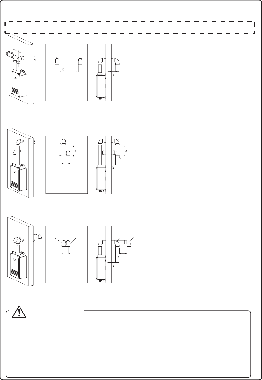
Intake and exhaust should face the same direction.
Intake and exhaust should keep the same
pressure zone.
2ft. Min
Interior View
Interior View Exterior View
Interior View Exterior View
1ft. Min1ft. Min
0
Insert the bird screen.
90° elbow vertical setting (downward).
0
Ensure at least 3ft (0.9m) or more distance between
the near edge of the air intake pipe or exhaust pipe
to the inside corner of a wall.
0
Ensure at least 2ft (0.6m) or more distance between
intake pipe and exhaust pipe.
The distance is measured at inside of pipe to inner
dimension.
0
Intake and exhaust should face the same direction.
Intake and exhaust should keep the same
pressure zone.
0
Insert the bird screen.
90° elbow vertical setting (downward).
0
Ensure at least 3ft (0.9m) or more distance between
edge of air intake pipe or exhaust pipe and corner wall.
0
Upper side is exhaust, lower side is intake.
The reverse connection is not allowed.
0
Ensure at least 1ft (0.3m) or more distance between
intake pipe and exhaust pipe.
The distance is measured at the outlets of
intake port (terminal) and exhaust port (terminal).
0
Intake and exhaust should face the same direction.
Intake and exhaust should keep the same
pressure zone.
0
Insert the bird screen.
90° elbow vertical setting (downward).
0
Ensure at least 3ft (0.9m) or more distance between
edge of air intake pipe or exhaust pipe and corner wall.
0
The side distant fr
om wall is intake, the side near the
wall is exhaust.
The reverse connection is not allowed.
0
Ensure at least 1ft (0.3m) or more distance between
intake pipe and exhaust pipe.
The distance is measured at inside of pipe to inner
dimension.
0
0
Exhaust
Intake
Exhaust Intake
1ft. Min
Exterior View
Exhaust
Exhaust
Intake
Intake
Exhaust Intake
3” Min
WARNING
If the distance between the air inlet and exhaust vent terminations is too short, the water heater
will draw in the exhaust gases through the intake. There is a risk of inadequate combustion air
for the water heater, increasing Carbon Monoxide (CO) emissions and noise due to vibration.
0Termination elbows must be oriented vertically, pointing directly downward. Attempts to prevent
exhaust air from entering the air inlet by angling termination elbows in directions other than
directly downward will increase the risk of freezing.
0Reversing the air intake and exhaust pipes is not allowed.
Carbon Monoxide (CO) emissions and noise due to vibration will increase.
3” Min
3” Min
5.9”
5.9”
5.9”
Do Not Use TWHHORHOOD as a vent termination unless there is at least 3ft. (0.9m) or more distance between the intake pipe and exhaust pipe.
Installations where 3ft (0.9m) distance cannot be met, use 90° elbows as the vent terminations as shown in the illustrations below.
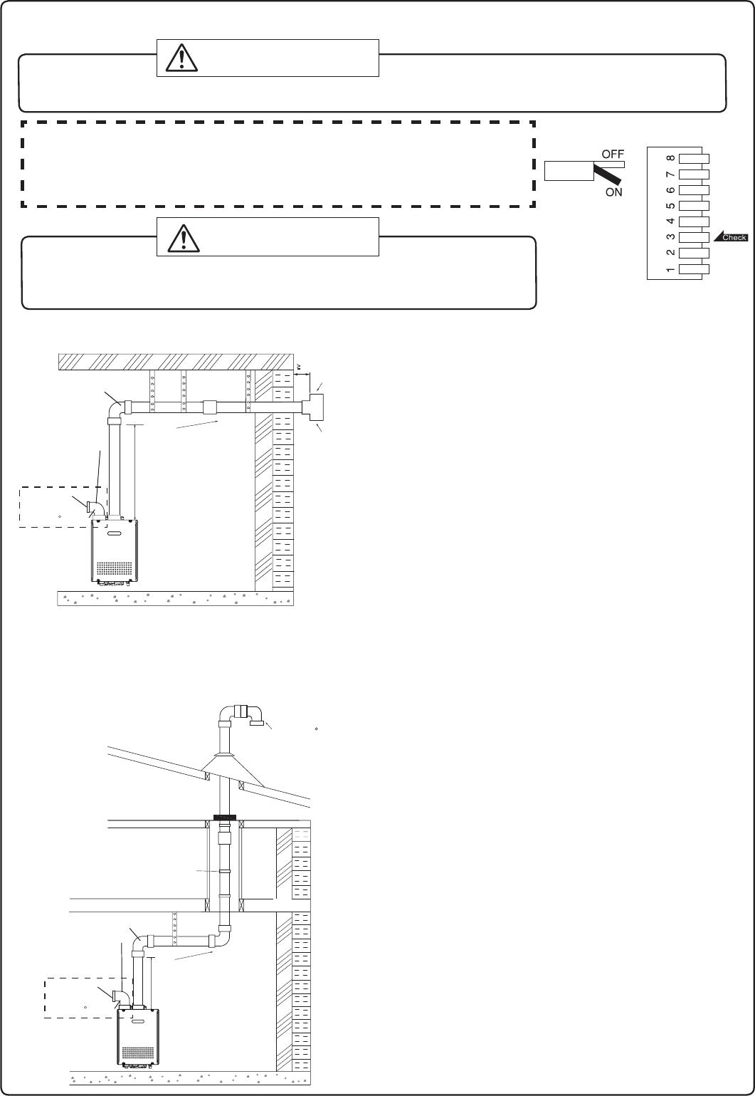
Vertical Vent Termination- PVC/CPVC Materials Only
Firestop
Firestop/Support
Roof
Flashing
Storm
Collar
Hanger
Strap
Horizontal Vent Termination- PVC/CPVC Materials Only
Hanger
Straps
**1' (0.3m) Minimum
Slope vent
Upwards
**1' (0.3m) Minimum
* Not supplied with water
heater, order separately.
recommended, but not required.
Insert Bird
Screen* in
Each End
of Tee
Support
Insert Bird
Screen* in
End of 90
Elbow
Slope vent
Upwards
* Not supplied with water
heater, order separately.
**1' (0.3m)
Minimum
**1' (0.3m) minimum
recommended, but not required.
D
D
D
D
D
D
D
D
D
D
D
D
D
D
D
A tee, 90° elbow, or the TWHHORHOOD termination may be
used for the vent termination. It is not necessary to use bird
screens with the TWHHORHOOD termination.
Terminate at least 12" (300mm) above grade or above snow line.
Terminate at least 7' (2.1m) above a public walkway, 6' (1.8m) from
the combustion air intake of any appliance, and 3' (0.9m) from
any other building opening, gas utility meter, service regulator etc.
Terminate at least 3' (0.9m) above any forced air inlet within
10' (3m) , 4' (1.2m) below, 4' (1.2m) horizontally from or
1' (0.3m) above any door, window, or gravity air inlet into any
building per National Fuel Gas Code ANSI Z223.1/NFPA 54.
Slope the horizontal vent 1/4" upwards for every 12" (300mm)
toward the termination.
Use a condensation drain if necessary.
In the Commonwealth of Massachusetts a carbon monoxide detector
is required for all side wall horizontally vented gas fuel equipment.
Please refer to Technical Bulletin TB 010606 for full installation
instructions.
The TWHVERTCAP termination may be used
in place of elbows as the vertical vent termination.
Terminate at least 6' (1.8m) from the combustion air
intake of any appliance, and 3' (0.9m) from any other
building opening, gas utility meter, service regulator etc.
Enclose exterior vent systems below the roof line to limit
condensation and protect against mechanical failure.
When the vent penetrates a oor or ceiling and is not
running in a re rated shaft, a restop and support is
required.
When the vent termination is located not less than
8' (2.4m) from a vertical wall or similar obstruction,
terminate above the roof at least 2' (0.6m), but not
more than 6' (1.87m), in accordance with the National
Fuel Gas Code ANSI Z223.1/NFPA 54.
Provide vertical support every 3' (0.9m) or as required
by the vent pipe manufacturer's instructions.
A short horizontal section is recommended to prevent
debris from falling into the water heater.
When using a horizontal section, slope the horizontal
vent 1/4” upwards for every 12” (300mm) toward the
termination to drain condensate.
Exhaust
Intake
Exhaust
Intake
90 Elbow
SV Conversion Kit
Accessory
(#SV-CK-3)
90 Elbow
SV Conversion Kit
Accessory
(#SV-CK-3)
Inlet screen
Inlet screen
3” Min.
* Dip switch No.3 is turned on.
Vent Pipe Installation (When supplying combustion air from the indoors (SV, non-direct vent))
t%JTDPOOFDUQPXFSBOEUVSO0/EJQTXJUDIJGDPNCVTUJPOBJSXJMMCFTVQQMJFEGSPNUIF
indoors as illustrated to the right. Refer to page 31 for the location of the dip switch bank.
t
SV Conversion kit #SV-CK-3 is required for the air intake. The SV Conversion Kit
#SV-CK-3 is contained within both the Horizontal Installation Kit (TWHHORKIT)
and the Vertical Installation Kit (TWHVERTKIT).
'BJMVSFUPQFSGPSNUIFBCPWFTUFQTDPVMESFTVMUJOBàSFPSFYQMPTJPODBVTJOH
property damage, personal injury or death.
3FGFSUPUIFJOTUSVDUJPOTQSPWJEFEXJUIUIFDPOWFSTJPOLJUGPSBEEJUJPOBMEFUBJMT
WARNING
When installing this water heater in an area with a large amount of lint such as a commercial Laundromat,
direct-vent ("-DV") system must be used. The "-SV" configuration (using an SV conversion kit) is prohibited.
DANGER
19
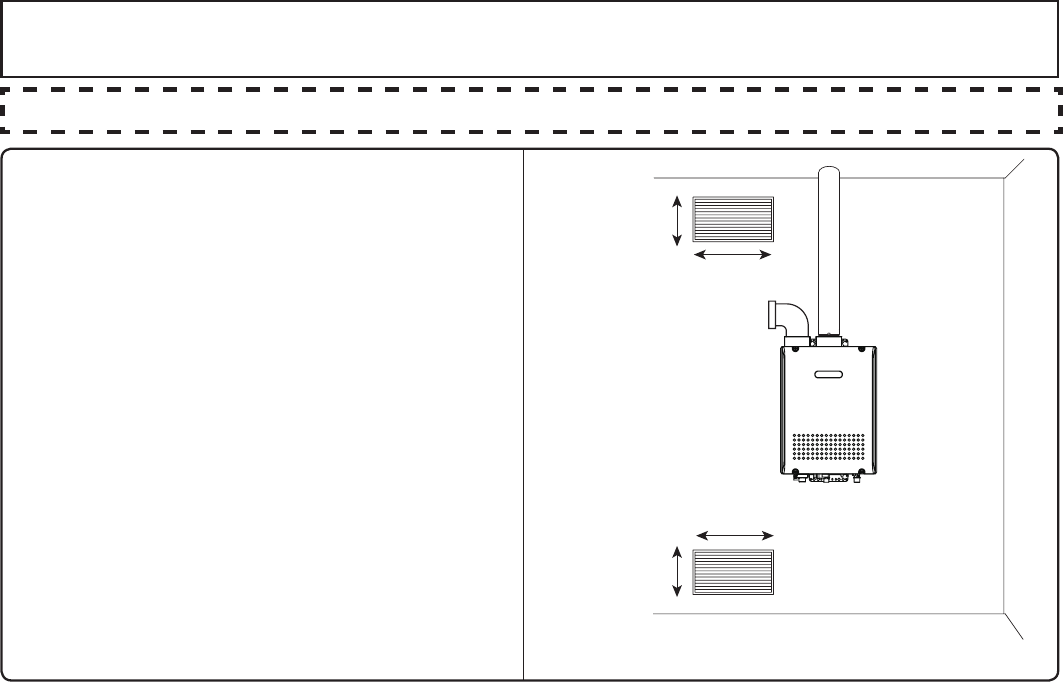
r1SPWJEFUXPQFSNBOFOUPQFOJOHTUPBMMPX
circulation of combustion air.
r.BLFFBDIPQFOJOHTRVBSFJODIFTJGUIFZ
provide indoor air, and 100 square inches for
outdoor air.
r*GUIFVOJUJTJOTUBMMFEJOBNFDIBOJDBMDMPTFU
QSPWJEFBNNDMFBSBODFJOGSPOUPG
the unit to the door.
r*GDPNCVTUJPOBJSXJMMCFQSPWJEFEUISPVHIB
duct, size the duct to provide 60 cubic feet of
fresh air per minute.
4VQQMZDPNCVTUJPOBJSUPUIFVOJUTBTQFSUIF/BUJPOBM'VFM(BT$PEF"/4*;
Combustion Air
Openings supplying indoor air
10" (250mm)
20" (500mm)
10" (250mm)
20" (500mm)
Provide adequate combustion air so as to not create negative pressure within the building.
20
Follow the instructions from the gas supplier.
Gas Type
The gas type indicated on the water heater rating plate (NG or LP) must match the type of gas being
supplied to the water heater.
Gas Conversions
If the gas type supplied does not match the gas type on the rating plate, obtain a replacement unit
with the proper gas type. If a gas type conversion must be made, there are conversion kits available
for some models. [The conversion kit shall be installed by an Electrolux authorized installer/servicer
in accordance with the manufacturer’s instructions and all applicable codes and requirements of the
authority having jurisdiction. The Electrolux authorized installer/servicer is responsible for the proper
installation of this kit. Improper installation of this kit will void the warranty.]
Meter
The gas meter must be sized properly for the water heater and other gas appliances to operate properly.
Select a gas meter capable of supplying the entire btuh demand of all gas appliances in the building.
9. Gas Piping
The guidelines and examples we have provided in this manual section are for reference only.
The sizing and installation of the gas system for this water heater, as with any gas appliance, is
the sole responsibility of the installer. The installer must be professionally trained to do such work
and must always follow all local and national codes and regulations. Gas line sizing calculations
must be performed for every installation. Please contact Electrolux Home Products, Inc. at 1-888-
360-8557 if you have any questions or concerns.
CAUTION
Regulators
Ensure that all gas regulators used are operating properly and providing gas pressures within the specied
range of the water heater being installed. Excess gas inlet pressure may cause serious accidents.
CAUTION
Pressure
Check the gas supply pressure immediately upstream at a location provided by the gas company.
Supplied gas pressure must be within the limits shown in the specications section with all gas appliances
operating. The inlet gas pressure must be within the range specied. This is for the purposes of input
adjustment. Low gas pressure may cause a loss of ame or ignition failure at other appliances in the home,
which may result in unburned gas in the home. Serious accidents such as re or explosion may result.
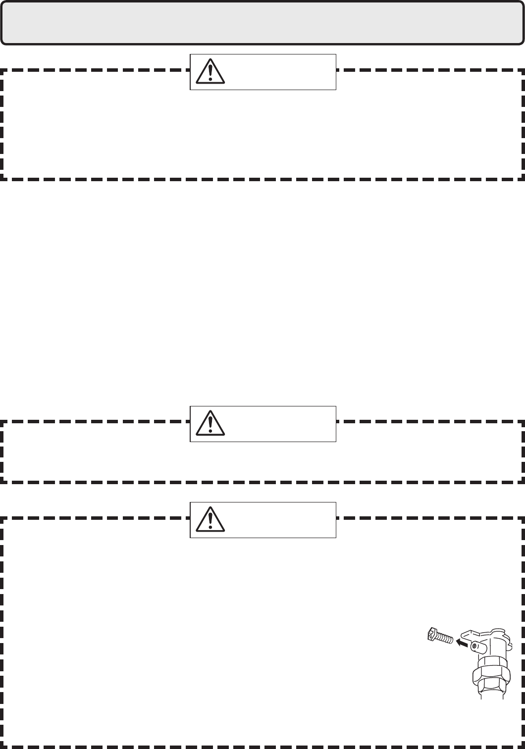
Measuring Gas Pressure
In order to check the gas supply pressure to the unit, a tap is provided on the
gas inlet. Remove the 9/32” hex head/Philips screw from the tap, and connect
a manometer using a silicon tube. Open up at least 2 xtures and hold in the
maximum manifold pressure button on the circuit board. Please call Electrolux
Home Products, Inc. for details.
NOTE* When checking the supply pressure, make sure to have all other gas appliances turned on
and running.
WARNING
21
Pressure Test
The appliance and its gas connections must be leak tested before placing the appliance in operation.
The appliance must be isolated from the gas supply piping system by closing its individual manual
shutoff valve during any pressure testing of the gas supply piping system at test pressures equal
to or less than ½ psig (3.5 kPa). We do not recommend pressure testing in excess of ½ psig
(3.5kPa). If it must be done, the appliance and its individual shutoff valve must be completely
disconnected from the gas supply piping system during the test process.
Pipe Sizing/Flexible Connectors
A gas shutoff valve must be installed on the supply line. Gas ex lines are not recommended unless
the minimum inside diameter is ¾” or greater and the rated capacity of the connector is equal to
or greater than the BTU capacity of the water heater. Gas piping shall be in accordance with local
utility company requirements and/or in the absence of local codes, use the latest edition of
National Fuel Gas Code (NFPA54GC), ANSI Z223.1. Size the gas line according to total btuh
demand of the building and length from the meter or regulator so that the following supply
pressures are available even at maximum demand.
WARNING
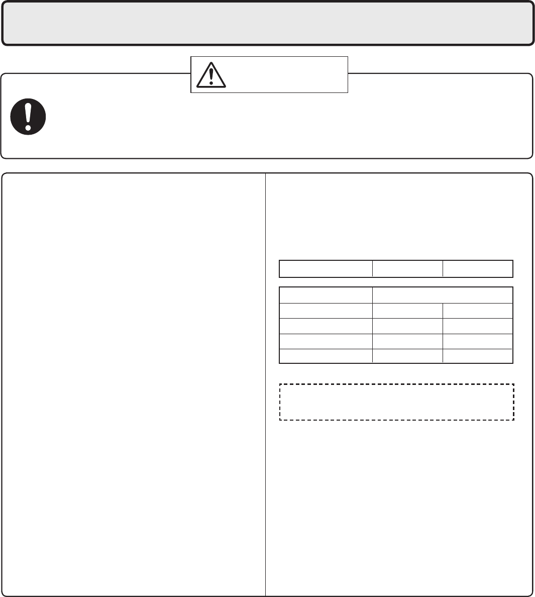
Natural Gas Supply Pressure
Min 4” WC
Max 10.5” WC
LP Gas Supply Pressure
Min 8” WC
Max 14” WC
Reference Tools & Sample Calculations
The tables and samples below are for reference only. The professional sizing and installing the gas
line should always run the appropriate calculations before all installations.
CAUTION
Which Table to Use
r'PS/(JOTUBMMBUJPOTXJUIUIFJOJUJBMTVQQMZQSFTTVSFBUQPJOUPGEFMJWFSZBUUIFNFUFSGPSFYBNQMFJT
less than 8” WC, use the 0.5” WC pressure drop table (Table 1).
r'PS/(JOTUBMMBUJPOTXJUIUIFJOJUJBMTVQQMZQSFTTVSFBUQPJOUPGEFMJWFSZJTHSFBUFSUIBOPSFRVBMUPu
WC, use the 3.0” pressure drop table (Table 2).
r'PSBMM-1JOTUBMMBUJPOVTF5BCMF
The inlet pressure must be at least 5” WC for NG or 8” WC for LP for all appliances in the gas system.
If the inlet gas pressure drops below 5” WC for NG or 8” WC for LP, the heater may continue to operate,
but the other appliances in the house may experience ame loss or ignition failure, which can result in
gas leakage into the home. Refer to the NFPA 54 for details.
Please contact Electrolux Home Products, Inc. for details. For corrugated stainless steel tubing (CSST)
capacity tables, please consult with the manufacturer.
22
Pipe
Size
Length (including ttings)
10' 20' 30' 40' 50' 60' 70' 80' 90' 100' 125'
(3m) (6m) (9m) (12m) (15m) (18m) (21m) (24m) (27m) (30m) (38m)
3/4" 360 247 199 170 151 137 126 117 110 104 92
1" 678 466 374 320 284 257 237 220 207 195 173
1 1/4" 1,390 957 768 657 583 528 486 452 424 400 355
1 1/2" 2,090 1,430 1,150 985 873 791 728 677 635 600 532
2" 4,020 2,760 2,220 1,900 1,680 1,520 1,400 1,300 1,220 1,160 1,020
2 1/2" 6,400 4,400 4,400 3,020 2,680 2,430 2,230 2,080 1,950 1,840 1,630
3" 11,300 7,780 7,780 5,350 4,740 4,290 3,950 3,760 3,450 3,260 2,890
4" 23,100 15,900 12,700 10,900 9,660 8,760 8,050 7,490 7,030 6,640 5,890
Table 1. For Less than 8” WC initial supply pressure
Maximum Natural Gas Delivery Capacity (0.5” Pressure Drop) [Schedule 40 Metalic Pipe]
Values in Table are in Cubic Feet of Gas per Hour (0.60 Specic Gravity, 0.5” Pressure Drop, inlet pressure less than 2psi). Contact your gas
supplier for BTU/Cubic Foot ratings. For simplication of your calculations, 1 Cubic Foot of Gas is approximately equivalent to 1000 BTU.
Instructions
1. Size each outlet branch starting from the furthest
using the Btuh required and the length from the meter.
2. Size each section of the main line using the length to
the furthest outlet and the Btuh required by everything
after that section.
Sample Gas Line
Sample Calculation - (Using 0.5” WC Pressure Drop T
able)
Outlet A: 45' (13.5m) (Use 50' (15m)), 50,000 Btuh requires 1/2"
Outlet B: 40' (12m), 65,000 Btuh requires 1/2"
Section 1: 45' (13.5m) (Use 50' (15m)), 115,000 Btuh requires 3/4"
Outlet C: 30' (9m), 35,000 Btuh requires 1/2"
Section 2: 45' (13.5m) (Use 50' (15m)), 150,000 Btuh requires 3/4"
Outlet D: 25' (7.5m) (Use 30' (9m)), 25,000 Btuh requires 1/2"
Section 3: 45' (13.5m) (Use 50' (15m)), 175,000 Btuh requires 1"
Outlet E: 25' (7.5m) (Use 30' (9m)), 199,900 Btuh requires 1"
Section 4: 45' (13.5m) (Use 50' (15m)), 374,900 Btuh requires 1 1/4"
Natural Gas
Meter
Electr
olux Condensing Tankless Gas Water Heater
(199,900 Btuh)
Clothes Dryer
(35,000 Btuh)
Barbecue
(50,000 Btuh)
Gas Range Stove
(65,000 Btuh)
10' (3m) 10' (3m)
10' (3m)
10' (3m)
5' (1.5m)
5' (1.5m)
5' (1.5m)
5' (1.5m)5' (1.5m) 5' (1.5m)
Gas Fireplace
(25,000 Btuh)
Section 3 Section 2 Section 1
Outlet A
Outlet B
Outlet C
Outlet D
Outlet E
Section 4
Table 2. For 8” WC – 10.5” WC initial supply pressure
Maximum Natural Gas Delivery Capacity (3.0” Pressure Drop) [Schedule 40 Metalic Pipe]
Values in Table are in Cubic Feet of Gas per Hour (0.60 Specic Gravity, 3.0” Pressure Drop, 8.0” WC or greater supply pressure, inlet
pressure less than 2psi). Contact your gas supplier for BTU/Cubic Foot ratings. For simplication of your calculations, 1 Cubic Foot of
Gas is approximately equivalent to 1000 BTU.
Natural Gas
Meter
Electr
olux Condensing Tankless Gas Water Heater
(199,900 Btuh)
Clothes Dryer
(35,000 Btuh)
Barbecue
(50,000 Btuh)
Gas Range Stove
(65,000 Btuh)
10' (3m) 10' (3m)
10' (3m)
10' (3m)
5' (1.5m)
5' (1.5m)
5' (1.5m)
5' (1.5m)5' (1.5m) 5' (1.5m)
Gas Fireplace
(25,000 Btuh)
Instructions
1. Size each outlet branch starting from the furthest
using the Btuh required and the length from the meter.
2. Size each section of the main line using the length to
the furthest outlet and the Btuh required by everything
after that section.
Sample Gas Line
Sample Calculation (Using 3.0” WC Pressure Drop T
able)
Outlet A: 45' (13.5m) (Use 50' (15m)), 50,000 Btuh requires 1/2"
Outlet B: 40' (12m), 65,000 Btuh requires 1/2"
Section 1: 45' (13.5m) (Use 50' (15m)), 115,000 Btuh requires 1/2"
Outlet C: 30' (9m), 35,000 Btuh requires 1/2"
Section 2: 45' (13.5m) (Use 50' (15m)), 150,000 Btuh requires 1/2"
Outlet D: 25' (7.5m) (Use 30' (9m)), 25,000 Btuh requires 1/2"
Section 3: 45' (13.5m) (Use 50' (15m)), 175,000 Btuh requires 1/2"
Outlet E: 25' (7.5m) (Use 30' (9m)), 199,900 Btuh requires 1/2"
Section 4: 45' (13.5m) (Use 50' (15m)), 374,900 Btuh requires 3/4"
Section 3 Section 2 Section 1
Outlet A
Outlet B
Outlet C
Outlet D
Outlet E
Section 4
Pipe
Size
Length (including ttings)
10' 20' 30' 40' 50' 60' 70' 80' 90' 100' 125'
(3m) (6m) (9m) (12m) (15m) (18m) (21m) (24m) (27m) (30m) (38m)
1/2" 454 312 250 214 190 172 158 147 138 131 116
3/4" 949 652 524 448 397 360 331 308 289 273 242
1" 1,787 1,228 986 844 748 678 624 580 544 514 456
1 1/4" 3,669 2,522 2,025 1,733 1,536 1,392 1,280 1,191 1,118 1,056 936
1 1/2" 5,497 3,778 3,034 2,597 2,302 2,085 1,919 1,785 1,675 1,582 1,402
2" 10,588 7,277 5,844 5,001 4,433 4,016 3,695 3,437 3,225 3,046 2,700
2 1/2" 16,875 11,598 9,314 7,971 7,065 6,401 5,889 5,479 1,540 4,856 4,303
3" 29,832 20,503 16,465 14,092 12,489 11,316 10,411 9,865 9,087 8,584 7,608
4" 43678 30,020 24,107 20,632 18,286 16,569 15,243 14,181 13,305 12,568 11,139
23
Table 3. Maximum Undiluted Propane (LP) Delivery Capacity in Thousands of
BtuH (0.5” WC Pressure Drop) [Schedule 40 Metalic Pipe]
For reference only. Please consult gas pipe manufacturer for actual pipe capacities.
Final Check
When the installation is complete, verify that inlet gas pressure for the entire gas system does not
drop below 5” WC for NG or 8” WC for LP at all appliances. This can be tested by turning on all
gas burning appliances including the water heater, then check the inlet pressure at each appliance
to verify all appliances are receiving a minimum of 5” WC for NG or 8” WC for LP. If all appliances
are not receiving the minimum inlet pressure the gas piping system may need to be changed.
CAUTION
Pipe
Size
Length (including ttings)
10' 20' 30' 40' 50' 60' 70' 80' 90' 100' 125' 150' 200'
(3m) (6m) (9m) (12m) (15m) (18m) (21m) (24m) (27m) (30m) (38m) (45m) (60m)
1/2" 275 189 152 129 114 103 96 89 83 78 69 63 55
3/4" 567 393 315 267 237 217 196 185 173 162 146 132 112
1" 1,071 732 590 504 448 409 378 346 322 307 275 252 213
1 1/4" 2,205 1,496 1,212 1039 913 834 771 724 677 630 567 511 440
1 1/2" 3,307 2,299 1,858 1,559 1,417 1,275 1,181 1,086 1,023 976 866 787 675
2" 6,221 4,331 3,465 2,992 2,646 2,394 2,205 2,047 1,921 1,811 1,606 1,496 1,260
24
10.
Water Piping
This appliance is suitable for combination potable water and space heating applications. It cannot be used for
space heating applications only. Do not use this appliance if any part has been underwater. Immediately call a
qualied service technician to inspect the appliance and replace any part of the control system and gas control
which has been under water.
If the water heater is installed in a closed water supply system, such as one having a backow preventer in the
cold water supply line, means shall be provided to control thermal expansion. Contact the water supplier or a local
plumbing inspector on how to control this situation.
A pressure relief valve must be installed near the hot water outlet that is rated in accordance with and complying
with either The Standard for Relief Valves and Automatic Shutoff Devices for Hot Water Supply Systems, ANSI
Z21.22, or The ANSI/ASME Boiler and Pressure Vessel Code, Section IV (Heating Boilers). This pressure relief
valve must be capable of an hourly Btu rated temperature steam discharge of 199,900 Btuh. Multiple valves may
be used. The pressure relief capacity must not exceed 150 psig. No valve shall be placed between the relief valve
and the water heater. The relief valve must be installed such that the discharge will be conducted to a suitable
place for disposal when relief occurs. No reducing coupling or other restriction may be installed in the discharge
line. The discharge line must be installed to allow complete drainage of both the valve and the line. If this unit is
installed with a separate storage vessel, the separate vessel must have its own temperature and pressure relief
valve. This valve must also comply with The Standard for Relief Valves and Automatic Gas Shutoff Devices for
Hot Water Supply Systems, ANSI Z21.22. (in the U.S. only). A temperature relief valve is not required, but if one is
used, do not install the valve with the probe directly in the ow of water. This may cause unwarranted discharge of
the valve.
Piping and components connected to the water heater shall be suitable for use with potable water.
Toxic chemicals, such as those used for boiler treatment, shall not be introduced into the potable water.
A water heater used to supply potable water may not be connected to any heating system or components
previously used with a nonpotable water heating appliance.
When water is required in one part of the system at a higher temperature than in the rest of the system, means
such as a mixing valve shall be installed to temper the water to reduce the scald hazard.
Installation and service must be performed by a qualied plumber. In the
Commonwealth of Massachusetts, this product must be installed by a licensed
plumber or gas tter in accordance with the Massachusetts Plumbing and Fuel
Gas Code 248 CMR Sections 2.00 and 5.00. Observe all applicable codes.
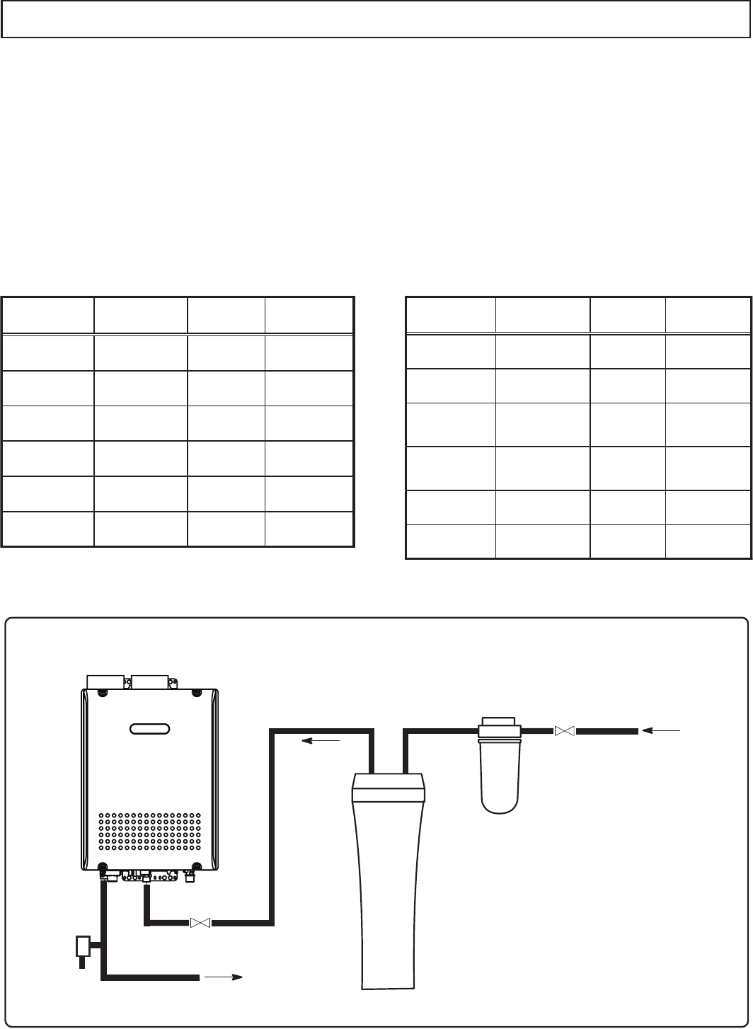
r 'MVTIXBUFSUISPVHIUIFQJQFUPDMFBOPVUNFUBMQPXEFSTBOEBOEEJSUCFGPSFDPOOFDUJOHJU
r 1FSGPSNUIFGPMMPXJOHJOTVMBUJPONFBTVSFTGPSQSFWFOUJPOPGGSFF[JOH
- Take appropriate heat insulation measures (e.g., wrapping with heat
insulation materials, using electric heaters) according to the climate
of the region to prevent the pipe from freezing.
- Make sure that there are no water leaks from the cold and hot water
supply pipes, then insulate the pipes completely.
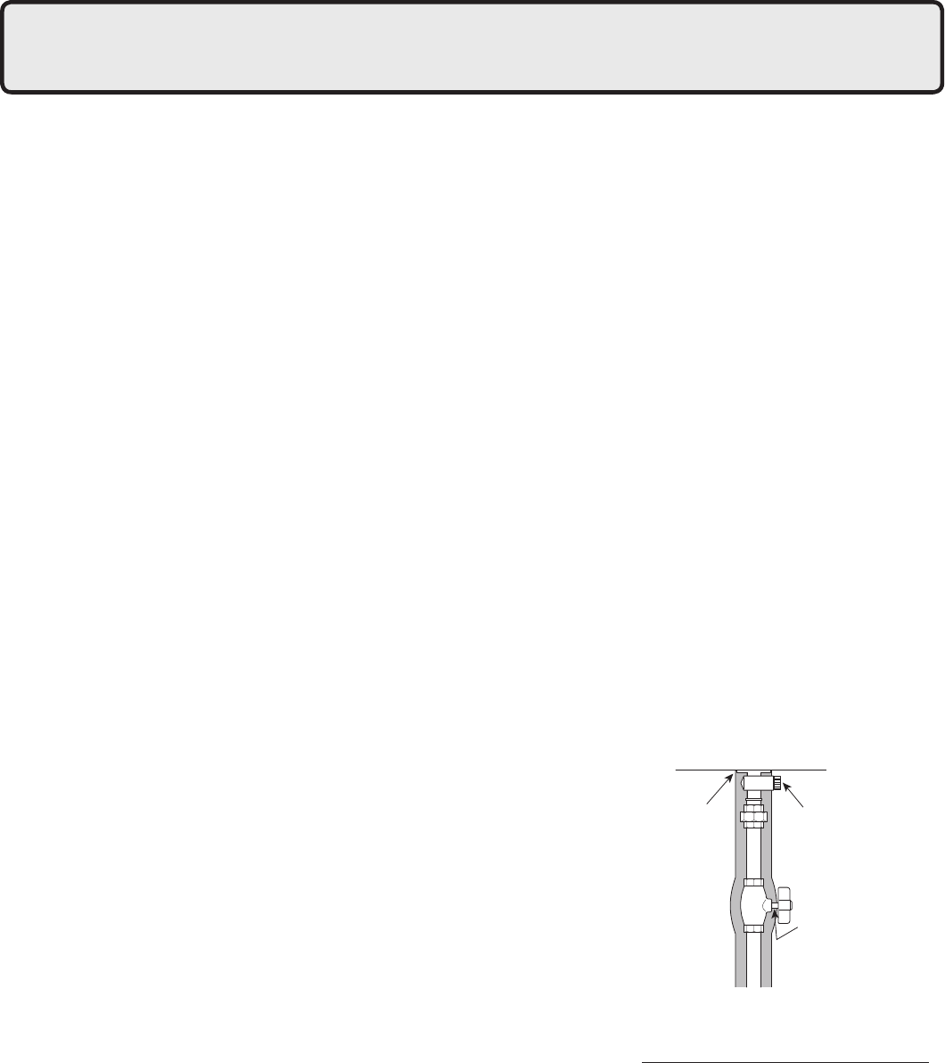
- Be sure to also completely insulate the water supply valve and the
cold and hot water connections on the water heater (refer to the gure
on the right).
- Do not cover the water drain plug with insulation so that water in the
pipe can be drained. (Refer to the gure in the right.)
r
Use a union coupling or exible pipe for connecting the pipes to reduce the force applied to the piping.
r %POPUVTFQJQJOHXJUIBEJBNFUFSTNBMMFSUIBOUIFDPVQMJOH
r 8IFOGFFEXBUFSQSFTTVSFJTUPPIJHIJOTFSUBEFQSFTTVSJ[JOHWBMWFPSUBLFwater hammer prevention measure.
r "WPJEVTJOHKPJOUTBTNVDIBTQPTTJCMFUPLFFQUIFQJQJOHTJNQMF
r "WPJEQJQJOHJOXIJDIBOBJSIPMEVQDBOPDDVS
r *GJOTUBMMJOHUIFVOJUPOBSPPG
- If the unit is installed on a roof to supply water to the levels below, make sure that the water pressure supplied
to the unit does not drop below 29 psi. It may be necessary to install a pump system to ensure that the water
pressure is maintained at this level.
- Check the pressure before putting the unit into operation.
- Failure to supply the proper pressure to the unit may result in noisy operation, shorter lifetime of the unit, and
may cause the unit to shut down frequently.
25
Supply water piping
r
Do not use PVC, iron, or any piping which has been
treated with chromates, boiler seal or other chemicals.
r
Mount a check valve and a shut off valve (near the inlet).
r*O PSEFS GPS UIF DMJFOU UP VTF UIF XBUFS IFBUFS
comfortably, 98.1 to 491 kPa (14 to 70 PSI) of
pressure is needed from the water supply.
Be sure to check the water pressure. If the
water pressure is low, the water heater cannot
perform to its full capability, and may become
a source of trouble for the client.
Drain piping
r&YQBOTJPOXBUFSNBZESPQGSPNUIFQSFTTVSF
relief valve and wet the oor.
If necessary, provide drain piping or use a
drain hose to remove the water.
Hot water piping
r%POPUVTFMFBE17$JSPOPSBOZQJQJOHXIJDI
has been treated with chromates, boiler seal or
other chemicals.
r5IFMPOHFSUIFQJQJOHUIFHSFBUFSUIFIFBUMPTT
Try to make the piping as short as possible.
r6TF NJYJOH WBMWFT XJUI MPX XBUFS SFTJTUBODF
Use shower heads with low pressure loss.
r*G OFDFTTBSZ VTF B QVNQ PS PUIFS NFBOT UP
ensure that the supply water pressure to the
inlet of the heater does not fall below 29 PSI
when the maximum amount of water is being
demanded. Also install a pressure meter on
the inlet. If this is not done, local boiling will
occur inside the water heater causing abnormal
sounds and decreasing the durability of the
heat exchanger.
Freeze Prevention
r'SFF[JOHJTQSFWFOUFEXJUIJOUIFEFWJDFBVUPNBUJDBMMZVOMFTTUIFPVUTJEFUFNQFSBUVSFXJUIPVUXJOE
is below -30°F (-35°C).
*
When combustion air is supplied from the indoors, the room temperature must be greater than
32°F
(0°C)
to prevent freezing and the room inside must not have negative pressure.
r*GUIJTNPEFMJTJOTUBMMFEJOBOBSFBXIFSFUIFPVUTJEFUFNQFSBUVSFDBOBQQSPBDIGSFF[JOHDPOEJUJPOT
of -30°F (-35°C) or below, then additional freeze protection measures must be used. For temporary
freeze protection measures, refer to the Use and Care Manual.
r5IFGSFF[FQSFWFOUJPOIFBUFSTXJMMOPUQSFWFOUUIFQMVNCJOHFYUFSOBMUPUIF VOJUGSPNGSFF[JOH
Protect this plumbing with insulation, heat tape or electric heaters, solenoids, or pipe covers.
r*OPSEFSGPSUIFGSFF[FQSFWFOUJPOIFBUFSTUPPQFSBUFUIFXBUFSIFBUFSNVTUIBWFQPXFSBUBMMUJNFT
26
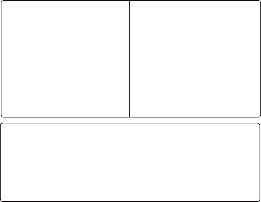
Water Treatment
Water Treatment System
City Water Supply
Pressure
Relief
Valve
Hot Water to Fixtures
Shutoff Valve
Drain
Cold to Water
Heater
Optional Sediment
Filter
Water Treatment Device
Shutoff Valve
TypeofWater
Hardness
Level
Treatment
Device
Flush
Frequency*
TypeofWater
Hardness
Level
Treatment
Device
Flush
Frequency*
Soft 0-1gpg
1-3gpg
(0-17mg/L)
None None None
None
None
None
SlightlyHard
(17-51mg/L)
None None
Moderately
Hard
Hard
3-7gpg
(51-120mg/L)
Once a Year** Once a Year
Twice a Year
Once a Year**
7-10gpg
(120-171mg/L)
VeryHard 10-14gpg
(171-239mg/L)
Water Softener
Treatment
Required
Extremely
Hard
Soft
SlightlyHard
Moderately
Hard
Hard
VeryHard
Extremely
Hard
> 14gpg
(> 239mg/L)
0-1gpg
1-3gpg
(0-17mg/L)
(17-51mg/L)
3-7gpg
(51-120mg/L)
7-10gpg
(120-171mg/L)
10-14gpg
(171-239mg/L)
> 14gpg
(> 239mg/L)
Treatment
Required
Treatment
Required
Treatment
Required
* Install Isolation Valves to allow for ushing.
** Flushing is required if a water treatment device is not installed.
Scale Inhibitor
Water Softener
Scale Inhibitor
Water Softener
Scale Inhibitor
Water Softener
Scale Inhibitor
**
**
* Install Isolation Valves to allow for ushing.
** Flushing is required if a water treatment device is not installed.
Residential Use Treatment Guidelines Commercial Use Treatment Guidelines
Electrolux
Condensing
Tankless Gas
Water Heater
Water Softener
Scale Inhibitor
Water Softener
Scale Inhibitor
Water Softener
Scale Inhibitor
Water Softener
Scale Inhibitor
If this water heater will be installed in an application where the supply water is hard, the water must be
treated with a water softener or scale inhibitor. Refer to the below tables for suggested treatment and
maintenance measures to be taken based on the water hardness level. Damage to the water heater
as a result of water in excess of 12 gpg (200 mg/L) of hardness is not covered by the Electrolux Home
Products, Inc. Warranty.
/PUF 8BUFSTPGUFOFSTNBZCFSFHVMBUFECZUIFMPDBMXBUFSKVSJTEJDUJPODPOTVMUXJUIUIFNBOVGBDUVSFS
for code, sizing, and installation
guidelines; the below diagram is for reference only.
27
r5IJTXBUFSIFBUFSJTBIJHIFGàDJFODZGVMMZDPOEFOTJOHBQQMJBODFXIJDIQSPEVDFTBDJEJDDPOEFOTBUF
during operation. The water heater incorporates a collection and removal system which must be
properly drained in order to ensure proper operation of this appliance.
r5IF Q) MFWFM PG UIF DPOEFOTBUF JT BQQSPYJNBUFMZ "O FYUFSOBM OFVUSBMJ[FS NVTU CF JOTUBMMFE PO UIF
drain piping prior to disposal when required by local code or when the condensate could cause damage.
r*GBOFYUFSOBMOFVUSBMJ[FSJTJOTUBMMFEQFSJPEJDSFQMBDFNFOUPGUIFOFVUSBMJ[JOHBHFOUXJMMCFSFRVJSFE
Refer to the instructions supplied with the neutralizer for suggested replacement intervals.
r*OPSEFSUPESBJOUIFDPOEFOTBUFBUISFBEFEàUUJOHJTQSPWJEFEBUUIFCBTFPGUIFXBUFSIFBUFS
Do not reduce the size of this tting or the drain piping to less than 1/2".
In cold climates, do not drain the condensate to the outdoors. If the drain pipe freezes during cold
weather, the pipe will not drain condensate and the unit will stop operating.
r6TFQMBTUJDQJQFTVDIBT17$GPSUIFESBJOMJOF%POPUVTFTUFFMCMBDLJSPOPSBOZPUIFSNBUFSJBM
which can corrode when placed into contact with acidic condensate.
r,FFQUIFMFOHUIPGUIFESBJOQJQFBTTIPSUBTQPTTJCMF-POHSVOTPSBQQMJDBUJPOTXIFSFUIFOFBSFTU
drain is above the water heater will require the use of a condensate pump. Size the pump to allow for
a maximum condensate discharge of 2 GPH from the water heater.
r)PSJ[POUBMSVOTNVTUCFTMPQFEQFSGPPUUPXBSETUIFESBJOPSDPOEFOTBUFQVNQ5IFDPOEFO-
sate will be discharged by gravity force only. Make the drain pipe run as short as possible.
r5IFFOEPGUIFESBJOQJQFNVTUOPUCFTVCNFSHFEJOXBUFSPSCMPDLFEJOBOZXBZ5PFOTVSFQSPQFS
drainage, leave the end of the drain pipe open to the atmosphere. Do not have a trap. Also, make
sure that there are no obstructions blocking the drain line from discharging condensate.
r#FTVSFUPDIFDLUIBUDPOEFOTBUFJTGSFFMZáPXJOHGSPNUIFESBJOQJQJOHBGUFSUIFTZTUFNIBTCFFO
installed. Condensate will begin owing out of the water heater within 15 minutes after operation has
started.
r5BLF NFBTVSFT UP QSFWFOU UIF DPOEFOTBUF ESBJO MJOFT GSPN GSFF[JOH JOTVMBUJPO IFBU UBQF FMFDUSJD
heaters, etc.).
11. Condensate Piping
Drain pipe
Drain connecting
supply
Heat insulation
material
Water heater
Do not pitch the drain line up
once a horizontal section has
been introduced.Always pitch
the drain line down to ensure
proper drainage.
Drain pipe
Due to the acidic nature of the condensate, be sure to properly drain and if necessary, treat the
condensate prior to disposal. Damage caused by improperly handled condensate is not covered
by the warranty.
CAUTION

28
Slope pipe downwards
1/4" per foot. The end of the drain pipe
must have an air gap.
The end of the drain pipe
must have an air gap.
Condensate piping to floor drain
Slope pipe downwards
1/4" per foot.
1/2" PVC pipe
1/2" PVC elbow 3/8" ID tubing*
* Install tubing according to pump
manufacturer's instructions.
Condensate piping with pump
Condensate pump
Floor drain
MAINTAIN CLEARANCE
1/2" PVC pipe
DO NOT ADD
ANY VALVES
Electrolux
Condensing
Tankless Gas
Water Heater
DO NOT ADD
ANY VALVES
Electrolux
Condensing
Tankless Gas
Water Heater
/PUF
If the drain line becomes clogged or frozen, condensate will back-up into the water heater and a "29"
error code will ash on the remote controller, ceasing operation. If this occurs, clear the clog or freeze
so that condensate can freely ow. Be sure to slope the drain pipe, use the appropriate size pipe, allow
the proper clearances, and apply freeze prevention measures (when necessary) to prevent the drain
line from clogging or freezing.
29
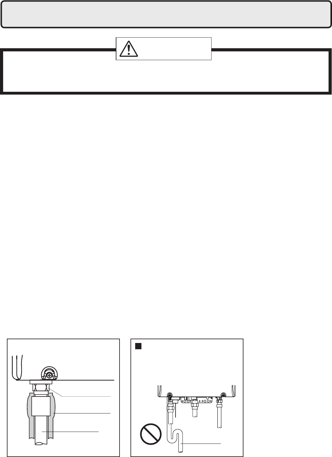
Recirculation System
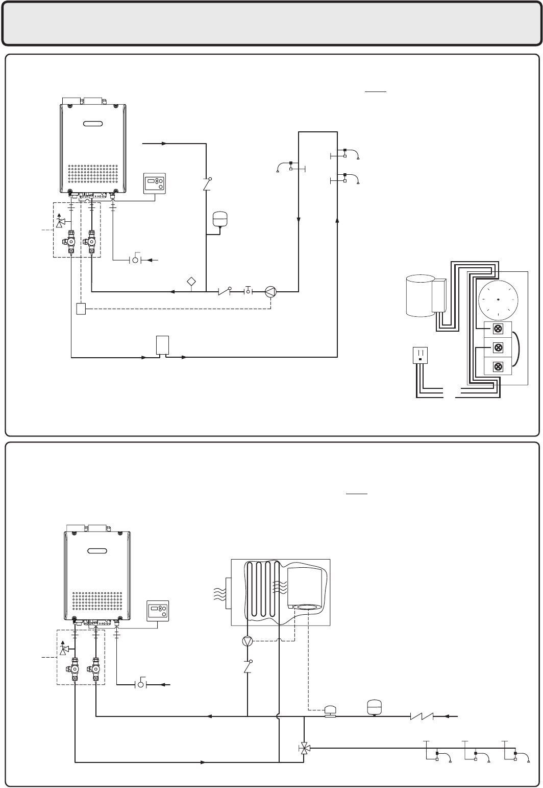
Combination Potable Water and Space Heating System
Cold Water Supply
Isolation
Kit(*4)
Gas Supply
Aquastat(*3)
Pump Control Signal(*2)
Relay for Pump
(if larger than 85 Watts)
Hot Water
Optional 8-10 Gallon
Storage Tank
(To alleviate cold water sandwich)
Globe
Valve
Pump(*1)
Expansion Tank
(Install according
to local code)
Fixtures
Hot Water Return
R
B
W
Pump
120VAC
105
Neutral
Ground
Live
S
Isolation
Kit(*1)
Gas Supply
Backow Preventer
(optional)
Check
Valve(*3)
Cold Water
Supply
Optional
Expansion Tank(*6)
Mixing Valve(*5)
Hot Water
Pump(*2)
Flow Switch(*4)
Fixtures
Air Handler
Notes:
1. Size the pump to provide a maximum of 2 GPM
(7.5 L/min.) through the system at 10 ft (3m) of
head plus piping losses.
Adjust the ow using a globe valve and verify the
ow rate with the maintenance monitors.
2. Pump Control Signal is the preferred method
to control the recirculation pump.
For pumps larger than 85W, a relay connection
must be used. If the Pump Control Signal is not
used, an Aquastat may be used to control the
pump.
3.
Use an Aquastat if the water heater is not controlling
the pump.
Set the Aquastat to 10°F (5°C) below the set
output temperature.
4.
Electrolux
recommends the use of an Isolation Kit
with the installation.
These kits include an integrated shut-off and service
valve with unions and a pressure relief valve.
Notes:
1.
Electrolux
recommends the use of an Isolation Kit with
the installation.
These kits include an integrated shut-off and service
valve with unions and a pressure relief valve.
2. Size the pump to provide
a maximum of
3 GPM
(11.3 L/min.) with a head pressure equal to the loss
through the water heater and Air Handler.
3
.
Check valve required if it is not included with the pump.
4.
Set the ow switch to deactivate the Air Handler when
the domestic hot water ow reaches 3 GPM (11.3 L/min.).
Adjust as necessary to prevent cycling.
5. If the system requires water for space heating at a higher
temperature than for other uses, means such as a
mixing valve shall be provided to temper the water for
the other uses to help prevent scalding.
7. The water heater cannot be used for space heating
applications only.
8. Only POTABLE water may be plumbed through
the water heater.
6. Expansion tank required if a backow preventer is installed.
Use Honeywell Aquastat
(Model L6006A or L6006C)
Aquastat Wiring
Electrolux
Condensing
Tankless Gas
Water Heater
Electrolux
Condensing
Tankless Gas
Water Heater
12. Plumbing Applications
30
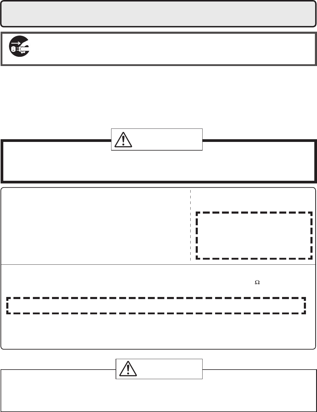
Do not connect electrical power to the unit until all electrical wiring has been completed.
Consult a qualied electrician
for the electrical work.
13. Electrical Wiring
This appliance must be electrically grounded in accordance with local codes, or in the absence of local
codes, with the National Electrical Code, ANSI/NFPA 70.
Caution: Label all wires prior to disconnection when servicing controls. Wiring errors can cause improper
and dangerous operation.
Verify proper operation after servicing.
Field wiring to be performed at time of appliance installation.
r5IFFMFDUSJDBMTVQQMZSFRVJSFECZUIFXBUFSIFBUFSJT
120VAC at 60 Hz.
The power consumption may be up to 306W or higher if
using optional accessories.
Use an appropriate circuit.
r%POPUEJTDPOOFDUUIFQPXFSTVQQMZXIFOOPUJOVTF8IFO
the power is off, the freeze prevention in the water heater
will not activate, resulting in possible freezing damage.
r%P OPU MFU UIF QPXFS DPSE DPOUBDU
the gas piping.
Tie the re d u n d a n t power cord
outside the water heater. Putting the
redundant length of cord inside the
water heater may cause electrical
interference and faulty
operation.
Disconnect Power
Electrical Shock Hazard
Do not turn power on until electrical wiring is nished. Disconnect power before servicing.
Failure to do so may result in death or serious injury from electrical shock.
WARNING
Electrostatic discharge can affect electronic components. Take precautions to prevent
electrostatic discharges from personnel or hand tools during the water heater installation and
servicing to protect product’s electronic control.
CAUTION
Ground
r5P QSFWFOU FMFDUSJDBM TIPDL QSPWJEF B HSPVOE XJUI SFTJTUBODF MFTT UIBO "O FMFDUSJDJBO
should do this work.
Do not connect the ground to the city water or gas piping. Do not tie the ground to a telephone line.
Breaker Installation
r.PVOUBEFWJDFXIJDITIVUTPGGUIFFMFDUSJDBMQBUIBVUPNBUJDBMMZMFBLBHFCSFBLFSXIFOFMFDUSJDBM
leakage is detected.
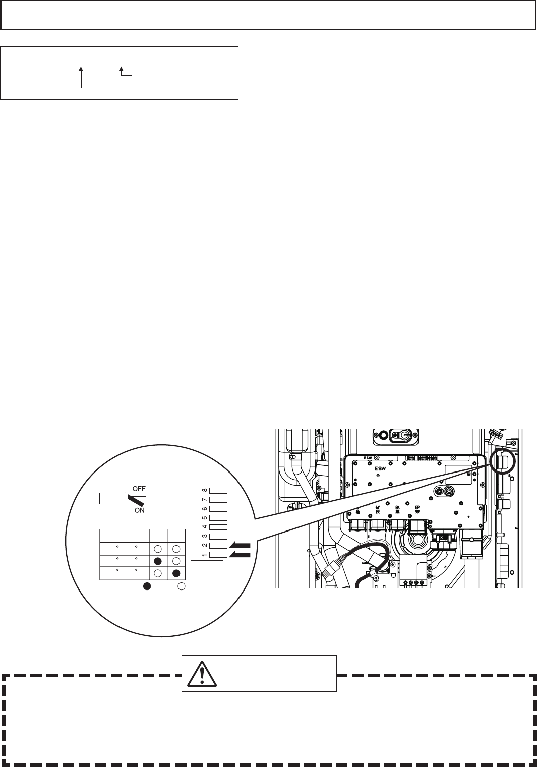
31
Remote Controller
Install the remote controller according to the instructions in the Installation Guide (page 38).
* Only one remote controller can be connected to the water heater.
A malfunction may occur if two or more remote controllers are connected.
* The water heater has been factory set to allow a maximum temperature setting of [120 °F / 50 °C].
To access higher temperature settings through the remote controller, follow the below steps.
<When setting the maximum temperature to [125 -140 °F / 55 - 60 °C]>
1. Turn the water heater off by pressing the Power On/Off Button on the remote controller.
2.
Press and hold the FLOW METER ALARM SET Button until a sound is heard (2 sec.) and
[120 °F / 50 °C]
appears on the display.
3.
Set the upper limit of the hot-water supply temperature to [125 °F, 130 °F, 135 °F or 140 °F / 55 °C or 60 °C]
using the UP and DOWN setting Buttons.
4. To put the water heater back into operation, press the Power On/Off Button on the remote controller.
To keep the water heater off, let the unit sit for 30 sec. to return to the original display.
r5IJT VOJU DBO CF QSPHSBNNFE TP UIBU JU XJMM EFGBVMU UP POF PG UISFF UFNQFSBUVSFT JG UIF SFNPUF
controller is removed [140 °F (60 °C), 135 °F (57 °C), 120 °F (50 °C)]. To change the default
temperature, adjust the dip switches as described below. The default temperature is 120 °F (50 °C).
1. Disconnect electrical power to the water heater.
2. Remove the front cover of the water heater (4 screws).
3. Disconnect the remote controller. Adjust the dip switches as illustrated below.
4. Replace the front cover of the water heater (4 screws).
5. Reconnect electrical power to the water heater.
r8IFODIBOHJOHUIFUFNQFSBUVSFNBLFTVSFUPDPOàSNXJUIUIFDVTUPNFSUIBUUIFUFNQFSBUVSF
of the hot water will be very high and that there is a risk of scalding.
r)PUXBUFSIFBUFSUFNQFSBUVSFTPWFS'$DBODBVTFTFWFSFCVSOTJOTUBOUMZPSEFBUI
from scalding.
DANGER
* Remarks [125 °F / 55 °C]
Fahrenheit display mode
Celsius display mode
* Do not change any other dipswitches.
* High temperature.
1 2
ON= OFF=
120 F (50 C)
135 F (57 C)
140 F (60 C)
Check
Check

32
Remote controller cord
r'PSFYUFOTJPOTVTF"8(XJSF
r*OTUBMMBDDPSEJOHUPUIF/BUJPOBM&MFDUSJDBM$PEFBOEBMMBQQMJDBCMFMPDBMDPEFT
Connecting Remote Controller Cord to Unit
r,FFQUIFSFNPUFDPOUSPMMFSDPSEBXBZGSPNUIFGSFF[FQSFWFOUJPOIFBUFSTJOUIFVOJU
r5JFUIFSFEVOEBOUDPSEPVUTJEFUIFXBUFSIFBUFS%POPUQVUUIFFYUSBMFOHUIJOTJEFUIFFRVJQNFOU
r5IFSFNPUFDPOUSPMMFSDPSEDBOCFFYUFOEFEVQUPhNXJUI"8(XJSF
r6TFB:UZQFUFSNJOBMXJUIBSFTJOTMFFWF8JUIPVUUIFTMFFWFUIFDPQQFSXJSFNBZDPSSPEFBOE
cause problems).
r#FTVSFUPIBOEUJHIUFOXIFOTDSFXJOHUPUIFUFSNJOBMCMPDL1PXFSUPPMTNBZDBVTFEBNBHFUP
the terminal block.
1. Check to make sure that the remote controller
cord has plenty of slack in order to reach the
external connection terminal block.
2. Disconnect electrical power to the water heater.
3. Remove the single screw securing the terminal
block cover and then remove the cover.
4.
Pass the remote controller cord through the wiring
UISPVHIXBZBOEDPOOFDUUIF:UFSNJOBMTBUUIFFOE
of the remote controller cord to the terminal block.
5. Replace the terminal block cover and install the
screw previously removed in step 3.
6. Reconnect electrical power to the water heater.
External connection
terminal block
Wiring throughway
Remote controller cord
Changing Other Features
Adjusting the Temperature Display
/PUF5IFTFUUJOHNVTUCFEPOFXJUIJOUIFàSTUNJOVUFTPGDPOOFDUJOHFMFDUSJDBMQPXFSUPUIFXBUFSIFBUFS
Table of Setting Items
Item No.
Item Choices (factory defaults shaded)
12 Celsius/Fahrenheit
display mode. °F (Fahrenheit) °C (Celsius)
Display Power On/Off Button
Flow Meter Alarm Set buttton
Setting Button
Setting Procedure
1. Turn the water heater off by pressing the Power On/Off Button on the remote controller.
2. Disconnect, then reconnect electrical power to the water heater.
3. Press the Flow Meter Alarm Set Button and hold it in for 2 seconds or more.
4. Press the Flow Meter Alarm Set Button until the remote controller displays item number "12".
5. Press Setting Button " " for 5 seconds or more to change the display units to °F.
6. Press Setting Button " " for 5 seconds or more to change the display units to °C.
7. To conrm the setting, turn the water heater on by pressing the Power On/Off Button on the
remote controller.
Remote Controller
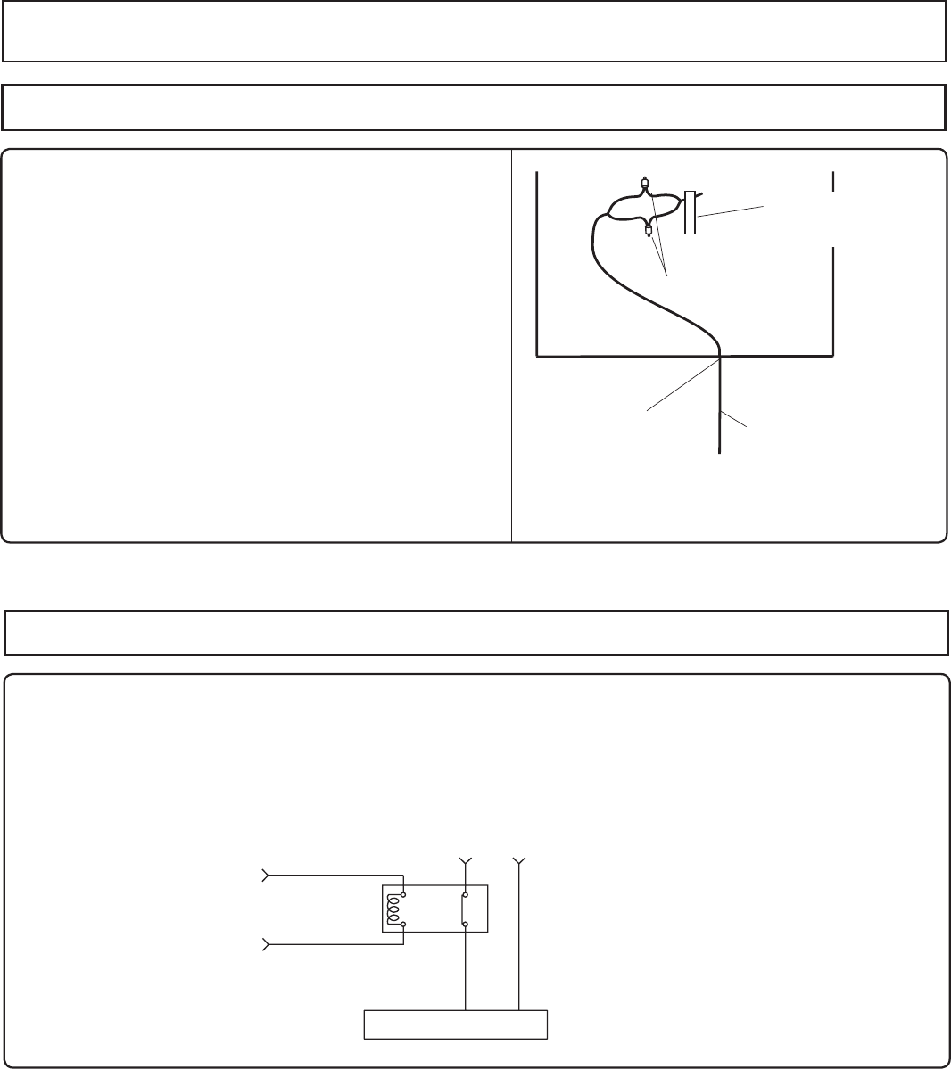
33
Connecting the pump control wire
1. Leave enough slack so that the pump control
wires will stay connected if the unit is removed
from the wall.
2. Remove the front cover of the heater (4 screws).
3. Cut off the connector at the end of the pump
control wires.
4. Wire the pump control wires through the wiring
throughway and connect them to the wiring inside
the pump (this will be the power supply for the pump,
do not also connect 120VAC to the pump).
If a large pump is being used (greater than 85W) use
the voltage from these wires as the signal to close a
normally open relay through which 120VAC will be
supplied directly from a wall circuit to the pump.
5. Replace the front cover.
Pump Wiring * This feature is not available when using the Quick
Connect Multi System feature.
Relay connection with larger pumps (>85 W)
1. Locate and prepare the pump control wires as described above.
2. Choose a suitable installation location for the relay where it will be protected from moisture.
3. Connect the pump control wires from the heater to the signal input on the relay.
4. Cut one of the electrical supply leads and wire it across the open terminals of the relay.
5. Secure all connections and replace the front cover of the heater.
Circulation Pump
120VAC
Relay (ex. Omron G7L2ABUBJCBAC120)
Connect to Pump Contr
ol
Wir
es in Unit
0
1
2
4
PUMP
Crimping Terminal
Wiring
Throughway Supplies Power for
Circulating Pump
(Use a Relay for
Larger Pumps)
Pump Control
Wire Tag
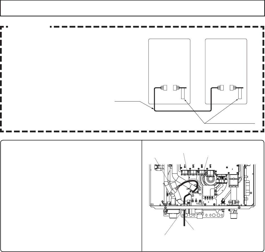
34
Connecting the Quick Connect Cord to the two units.
1. Turn off the power.
2. Remove the front cover of the heater (4 screws).
3. Pass the Quick Connect Cord through the wiring
throughway and into the unit.
4. Plug the connector on the Quick Connect Cord
to the receptacle inside the unit.
5. Attach the ground wire of the Quick Connect
Cord to the terminal block xing plate.
(If the ground wire is not attached, electrical
noise may cause problems).
6. Secure the Quick Connect Cord with a clamp.
7. Replace the front cover. Wiring Throughway
Coupling Cord
Clamp Ground wire Connector
Connector
Connecting Quick Connect Cord-2
Caution
For Quick Connect Multi System Installation
use part TWHQCCORD only. (Sold Separately)
Quick Connect
Cord-2
"Quick Connect Cord-2" tag
A B
1.Red
2.Black
3.White
4.Green
5.Blue
6.Blue
1.Red
2.Black
3.White
4.Green
5.Blue
6.Blue
1.Red
2.Black
3.White
4.Green
5.Blue
6.Blue
1.White
2.Green
3.Red
4.Black
5.Blue
6.Blue
The wire coloring on the Quick Connect Cord-2
will
not be the same as the wire coloring of the
connection plug inside the unit.
* The remote controller can be connected to
either unit A or B. Do not connect a remote
controller to both units.
* Disconnect the remote controller from either
unit A or B prior to installing the Quick Connect
Cord.
35
(1) Open a hot water xture and conrm that the Burner On lamp comes on, and that hot water is
being produced. (If necessary, repeat until the air in the gas piping is bled out).
* White smoke may be noticed from the exhaust vent during cold weather. However, this is not
a malfunction of the unit.
* If an “11” error code appears on the remote controller, turn the unit off and then back on
again, and then open a hot water xture again.
(2) Change the temperature setting on the remote controller and check that the water temperature changes.
r
If the water heater does not operate normally, refer to “Troubleshooting” in the Use and Care Manual.
* After the trial operation, clean the lter in the cold water inlet.
<If installed with a quick connect multi-system>
r5VSOUIFTZTUFNQPXFS0/XJUIUIFSFNPUFDPOUSPMMFS
r4MPXMZPQFOBIPUXBUFSàYUVSFBOEDIFDLUIBUUIFVOJUTJHOJUFTFRVFOUJBMMZ$IFDLUPTFFUIBUUIF
hot water temperature is the same as the temperature displayed on the remote controller. (*1)
* If both units do not ignite, switch which unit will ignite rst by pressing the Max. or Min. Mani-fold
Pressure Set Button on the circuit board. (*2)
* If an 11 or F11 error code ashes on the remote controller, hit the Power Button on the remote
controller off and on 2 -3 times.
* If (*1) and (*2) cannot be done, the Quick Connect Cord may not be properly connected.
Check that the cord is properly connected.
14. Maintenance Periodically check the following to ensure proper
operation of the water heater.
r5IFWFOUJOHTZTUFNNVTUCFFYBNJOFEQFSJPEJDBMMZCZBRVBMJàFETFSWJDFUFDIOJDJBOUPDIFDLGPS
any leaks or corrosion.
r5IFCVSOFSáBNFNVTUCFDIFDLFEQFSJPEJDBMMZGPSBQSPQFSCMVFDPMPSBOEDPOTJTUFODZ
r*GUIFáBNFEPFTOPUBQQFBSOPSNBMUIFCVSOFSNBZOFFEUPCFDMFBOFE
r*GUIFCVSOFSOFFETUPCFDMFBOFEJUNVTUCFQFSGPSNFECZBRVBMJàFETFSWJDFUFDIOJDJBO
r%POPUPCTUSVDUUIFáPXPGDPNCVTUJPOBOEWFOUJMBUJPOBJS
r5IFQSFTTVSFSFMJFGWBMWFNVTUCFPQFSBUFEPODFBZFBSUPFOTVSFUIBUJUJTGVODUJPOJOHQSPQFSMZBOE
there is no obstruction. Turn the power off to the unit before opening the relief valve, and make
sure that water draining out of the valve will not cause any damage.
r*GUIFSFMJFGWBMWFEJTDIBSHFTQFSJPEJDBMMZJUNBZCFEVFUPUIFSNBMFYQBOTJPOJOBDMPTFEXBUFS
system. Contact the water supplier or a local plumbing inspector on how to correct this situation.
Do not plug the relief valve.
r4FF6TFBOE$BSF.BOVBMGPSGVSUIFSNBJOUFOBODF
Warning:
There is a scald potential if the output temperature is set too high.
Should overheating occur, or the gas supply fail to shut off, turn off the manual gas control valve to the appliance.
Do not use this appliance if any part has been under water. Immediately call a qualied service
technician to inspect the appliance and to replace any part of the control system and any gas control
which has been under water.
Periodically check and clean the lter inside the cold water inlet of the unit.
15. Trial Operation
The installer should test operate the unit, explain to
the customer how to use the unit, and give the owner
this manual before leaving the installation.
Unit A Ignites
Unit B Doesn't Ignite
Press Max. or Min. Manifold
Pressure Set Button on Unit B Unit A Doesn't Ignite
Unit B Ignites
r 1SFQBSBUJPO 0QFOBIPUXBUFSàYUVSFUPDPOàSNUIBUXBUFSJTBWBJMBCMFBOEUIFODMPTF
the xture.
(2) Open the gas supply valve.
(3) Turn on the power supply. Using the remote controller, turn on the Power
On/Off button (the Operation lamp will turn on).
36
Lighting Instructions
This water heater does not have a pilot. It is equipped with an ignition device that automatically
lights the burner.
Do not try to light the burner by hand.
1. Read the safety information in the installation manual or on the front of the water heater.
2. Turn off all electrical power to the unit.
3. Do not attempt to light the burner by hand.
4. Turn the gas control manual valve (external to the unit) clockwise to the off position.
5. Wait five minutes to clear out any gas. If the smell of gas remains, stop, and follow the
instructions on page 3 of Use and Care Manual.
6. Turn the gas control manual valve counterclockwise to the on position.
7. Turn on electric power to the unit.
8. The unit will now operate whenever hot water is called for. If the unit will not operate, follow the
shutdown instructions and call a service technician.
Shutdown Instructions
1. Stop any water demand.
2. Turn off electric power.
3. Turn the gas control manual valve clockwise to the off position.
Should overheating occur, or the gas supply fail to shut off, turn off the manual control valve to the appliance.
Handling after trial operation
r *GUIFVOJUXJMMOPUCFVTFEJNNFEJBUFMZDMPTFPGGBMMHBTBOEXBUFSTIVUPGGWBMWFTESBJOBMM
of the water out of the unit and the plumbing system to prevent the unit and system from
freezing, and bleed the gas out of the gas line.
Freezing is not covered by the warranty.
CAUTION
A re or explosion may result if these instructions are not followed, which may cause loss
of life, personal injury or property damage.
WARNING
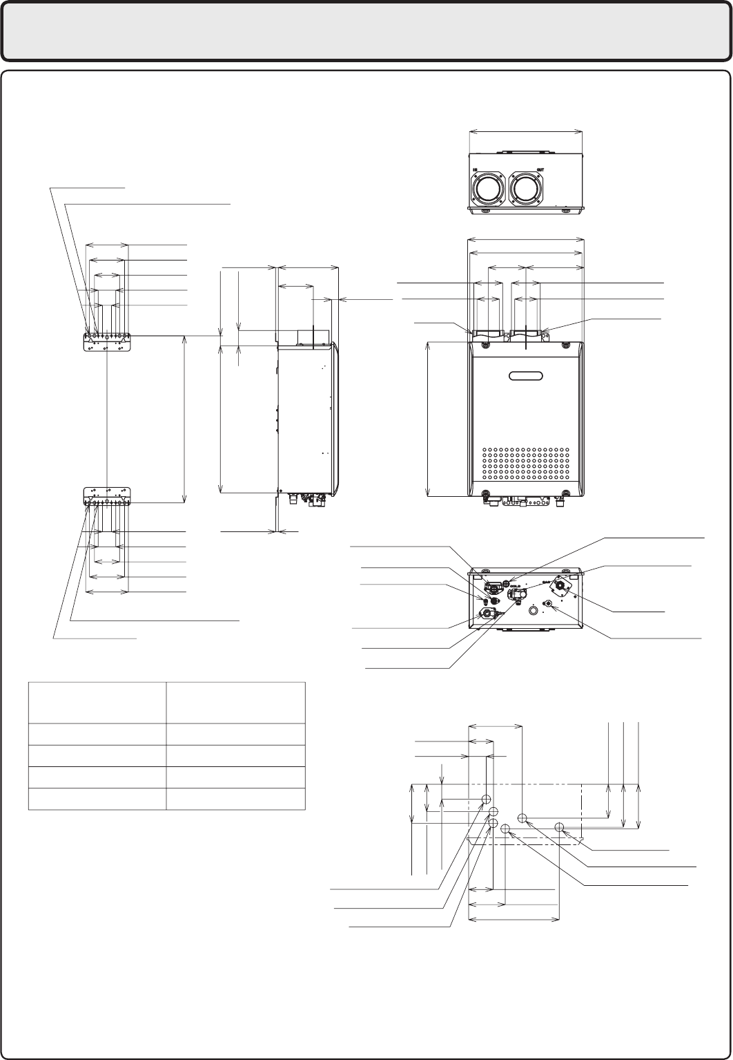
37
16. Dimensions
WATER DRAIN VALVE
COLD WATER INLET
WATER DRAIN VALVE
HOT WATER OUTLET
WATER DRAIN VALVE
CONDENSATE DRAIN
WIRING THOROUGHWAY
GAS INLET
(WATER FILTER)
WATER DRAIN VALVE
WIRING THOROUGHWAY
(AC120V)
AIR INLET FLUE COLLAR
(VIEW FROM TOP)
HOT WATER OUTLET (3/4")
CONDENSATE DRAIN (1/2")
WIRING THOROUGHWAY
WIRING THOROUGHWAY
COLD WATER INLET (3/4")
GAS INLET (3/4")
2.2" (56mm)
2.2" (55mm)
1.7" (44mm)
0.8" (20mm)
EN19WI30LS
EP19WI30LS
GAS INLET
COLD WATER INLET
HOT WATER OUTLET
CONDENSATE DRAIN
FROM BOTTOM OF CASE
HEIGHT OF EACH FITTING
6.7" (170mm)
5.5" (140mm)
3.9" (100mm)
2.8" (70mm)
1.4" (36mm) 0.4" (10mm)
4 - Ø0.5" (Ø13mm)
6 - 0.24" x 0.4" (6 x 10mm) OBLONG HOLE
1.6" (40mm)
5.3" (135mm)
6.1" (155mm)
4.3" (109mm)
2.4" (60mm)
6.7" (171mm)
7.0" (177mm)
26.2" (665mm)
23.1" (586mm)
24.4" (619mm)
2.4" (61mm)
0.4" (10mm) 9.4" (240mm)
5.5" (140mm)
1.1" (28mm)
Ø4.5" (Ø114mm)
Ø3.5" (Ø89mm)
17.7" (450mm)
18.4" (468mm)
17.6" (448mm)
5.9" (150mm) 9.1" (232mm)
Ø4.5" (Ø114mm)
Ø3.5" (Ø89mm)
8.4" (214mm)
3.9" (99mm)
2.8" (70mm)
14.2" (362mm)
5.7" (146mm)
3.9" (98mm) (AC120V)
< inch (mm) >
4 - Ø0.5" (Ø13mm)
6 - 0.24" x 0.4" (6 x 10mm) OBLONG HOLE
6.7" (170mm)
5.5" (140mm)
3.9" (100mm)
2.8" (70mm)
1.4" (36mm)
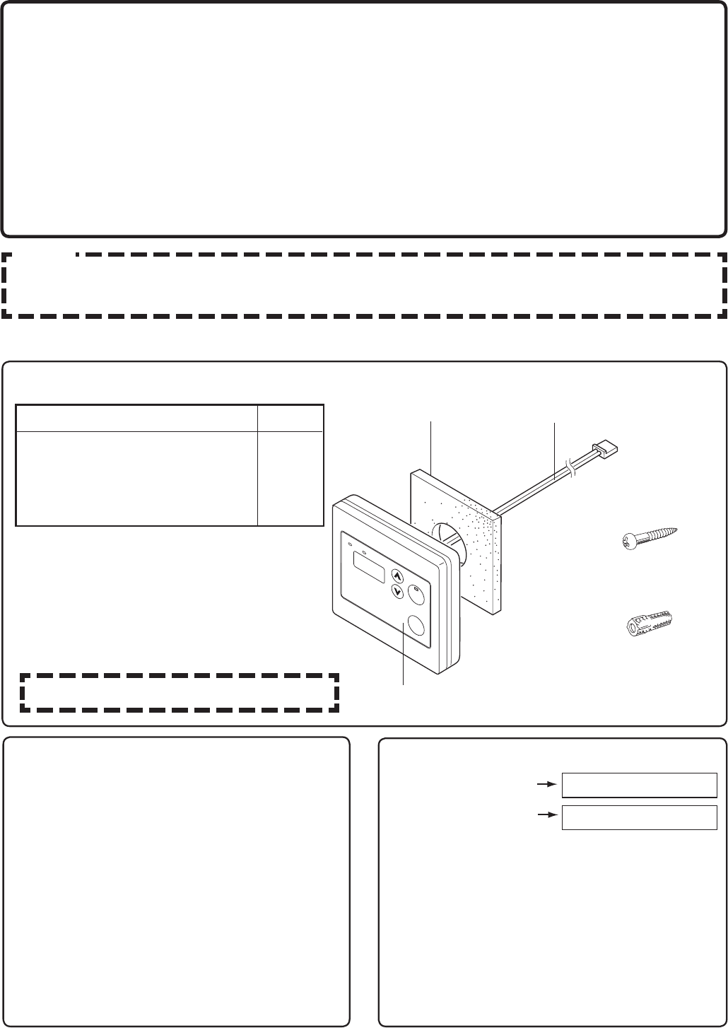
38
Included Parts List
Remote Controller
Installation Guide
For Installers:
Read this installation guide
carefully before carrying out
installation.
Electrolux Home Products, Inc.
Note
Do not connect power to the water heater before the remote controller has been properly installed.
Recommended installation location of the remote controller is in a bathroom.
Do not disassemble the remote controller.
Wall Packing Connecting Wire
Remote Controller
Phillips Roundhead
Wood Screw
Wall Anchor
Part Name
Remote Controller
Wall Packing
Phillips Roundhead Wood Screw
Wall Anchor
Quantity
1
1
2
2
Notes on the Installation Location
r5IFSFNPUFTIPVMECFJOTUBMMFEJOBOFBTJMZ
accessible location.
r"WPJE JOTUBMMJOH JO B QMBDF XIFSF XBUFS
or steam can come into contact with the
controller.
r
Avoid locations where special chemical agents
(e.g., benzene, fatty and oily detergents)
are used.
r"WPJEPVUEPPSJOTUBMMBUJPOPSJOTUBMMBUJPO JO
an indoor location where it will be exposed
to direct sunlight.
Connection of Remote Controller Cord
White Connector
To Remote Controller
:TIBQFEUFSNJOBMT 5P8BUFS)FBUFS
(two-core)
* Conrm the connection with the labels at
both ends of the remote controller cord.
r5IFSFNPUFDPOUSPMMFSDPSEDBOCFFYUFOEFE
up to 300 ft (90m). by splicing the cord and
using 18 gauge wire to extend the cord to
the appropriate length.
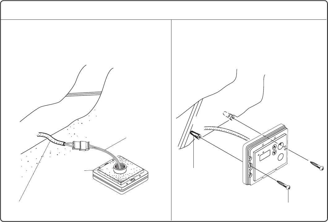
39
Installation
1. Apply Wall Packing to the rear side of the
remote controller.
2. Connect the remote controller wires to the
separate remote controller cord.
Phillips Roundhead
Wood Screw
Wall Anchor
3. Remove the cover of the remote control,
mark the location of the screw holes, and
drill holes for the wall anchors.
4. Insert the wall anchors, screw the remote
control to the wall and replace the cover.
Remote Controller Cord
Wall Packing
(take off the paper)
Remote
Control
Wires
Rear Side of
Remote Controller


EN CONDENSING TANKLESS GAS WATER HEATER Installation Manual
SBB800T-1
Rev. 09/13
*SBB800T*
SP CALENTADOR A GAS TIPO CONDENSADO Manual de Instalación
5995615357 Septiembre 2013
Manual de Instalación
EN19WI30LS
EP19WI30LS
Los peligros potenciales de accidentes durante la instalación y el uso se dividen en las siguientes
tres categorías. Respete cuidadosamente estas advertencias, que son esenciales para su seguridad.
Prohibido Desconectar
Alimentación Tierra Asegúrese de
hacerlo
ADVERTENCIA: Si la información contenida en este manual no se sigue con exactitud, se puede
provocar un incendio o una explosión causando daños materiales, lesiones personales o la muerte.
PELIGRO indica una situación inminente de peligro que, si
no se evita, causará la muerte o lesiones graves.
ADVERTENCIA indica una situación potencialmente peligrosa que,
si no se evita, podría causar la muerte o lesiones graves.
PRECAUCIÓN indica una situación potencialmente peligrosa que,
si no se evita, puede provocar lesiones leves o moderadas.
PELIGRO
ADVERTENCIA
PRECAUCIÓN
Peticiones a los instaladores
Para utilizar el calentador de agua con seguridad, lea este manual de instalación
cuidadosamente, y siga las instrucciones de instalación.
Los fallos y daños causados por trabajos erróneos o realizados sin seguir las instrucciones de
este manual no están cubiertos por la garantía.
Al terminar, compruebe que la instalación se ha realizado correctamente según este Manual de Instalación.
Después de terminar la instalación, coloque este Manual de Instalación en una bolsa plástica y
fíjelo al lado del calentador de agua (o dentro de la cubierta de la tubería o de la caja empotrable,
si procede),
o entrégueselo al cliente para que lo utilice en futuras referencias. También,
asegúrese de llenar todos los elementos necesarios en la tarjeta del registro/garantía y
entregársela al cliente junto con el Manual de Uso y Cuidado.
PRECAUCIÓN
PARA USO EN APLICACIONES RESIDENCIALES EN LOS ESTADOS
UNIDOS SOLAMENTE. NO DISEÑADO PARA EL USO EN CANADÁ O
MÉXICO.
La instalación debe cumplir con los códigos locales, o en ausencia de
códigos locales,
con el Código Nacional de Gas Combustible, ANSI
Z223.1/NFPA 54 - última edición.
Electrolux Home Products, Inc. se reserva el derecho de
descontinuar, o cambiar en cualquier momento, los diseños y/o
especicaciones de sus productos sin previo aviso.
Low NOx
Aprobado por
SCAQMD
14 ng/J or 20 ppm
(Solo Gas Natural)
CALENTADOR A GAS TIPO CONDENSADO
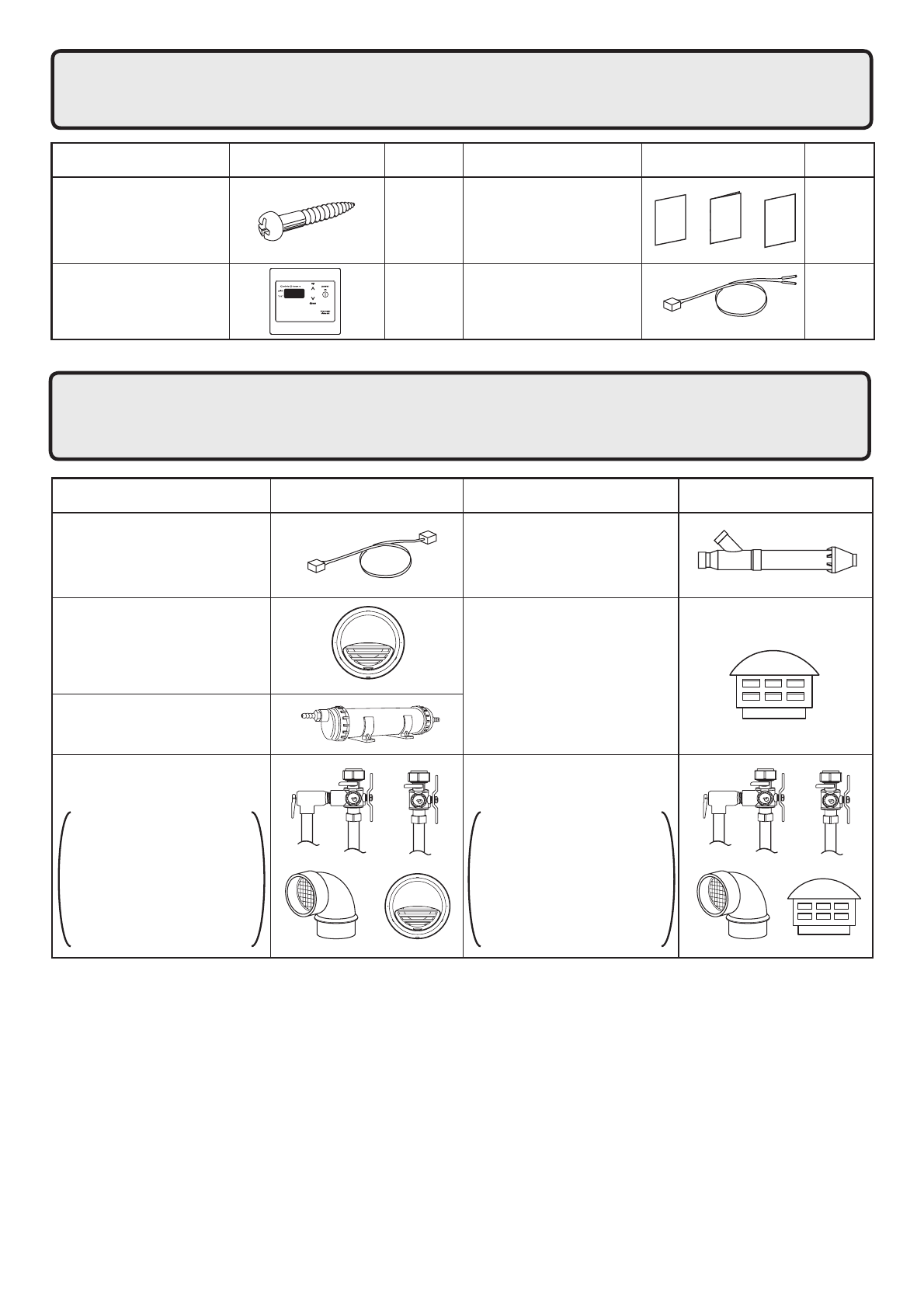
2
1.
Accesorios Incluídos
Los siguientes accesorios están incluidos con la unidad.
Compruebe los componentes que faltan antes de
comenzar la instalación.
Cantidad
FormaPieza
1
cada
uno
Pieza Forma Cantidad
5
1
Control Remoto
(ver página 31)
Cable del Control
Remoto (6 pies (2m))
(RC-CORD6)
1
Manual de Uso y Cuidado.
Garantía, Manual de
Instalación
(este documento)
Tornillo de jación
2.
Accesorios Opcionales
Los accesorios indicados a continuación no se incluyen con
las unidades, pero pueden ser necesarios para la instalación.
Póngase en contacto con Electrolux Home Products, Inc. en
el 1-888-360-8557 para más información.
Cable de Conexión Rápida
TWHQCCORD
3" (75mm) Terminal PVC
TWHHORCONC
3" (75mm) / 4" (100mm)
Terminación de capucha
Horizontal
TWHHORHOOD
3" (75 mm) / 4" (100 mm)
Terminación del capuchón
de lluvia vertical
TWHVERTCAP
Kit de instalación horizontal
TWHHORKIT
Válvulas aisladoras,
Válvula de liberación
de presión,
Terminación de la
capucha horizontal,
Kit de conversión SV
(#SV-CK-3)
Kit de instalación vertical
TWHVERTKIT
Válvulas aisladoras,
Válvula de liberación
de presión,
Terminación del capuchón
de lluvia vertical,
Kit de conversión SV
(#SV-CK-3)
Kit de Neutralizador
TWHNEUTRAL
FormaPiezaPieza Forma
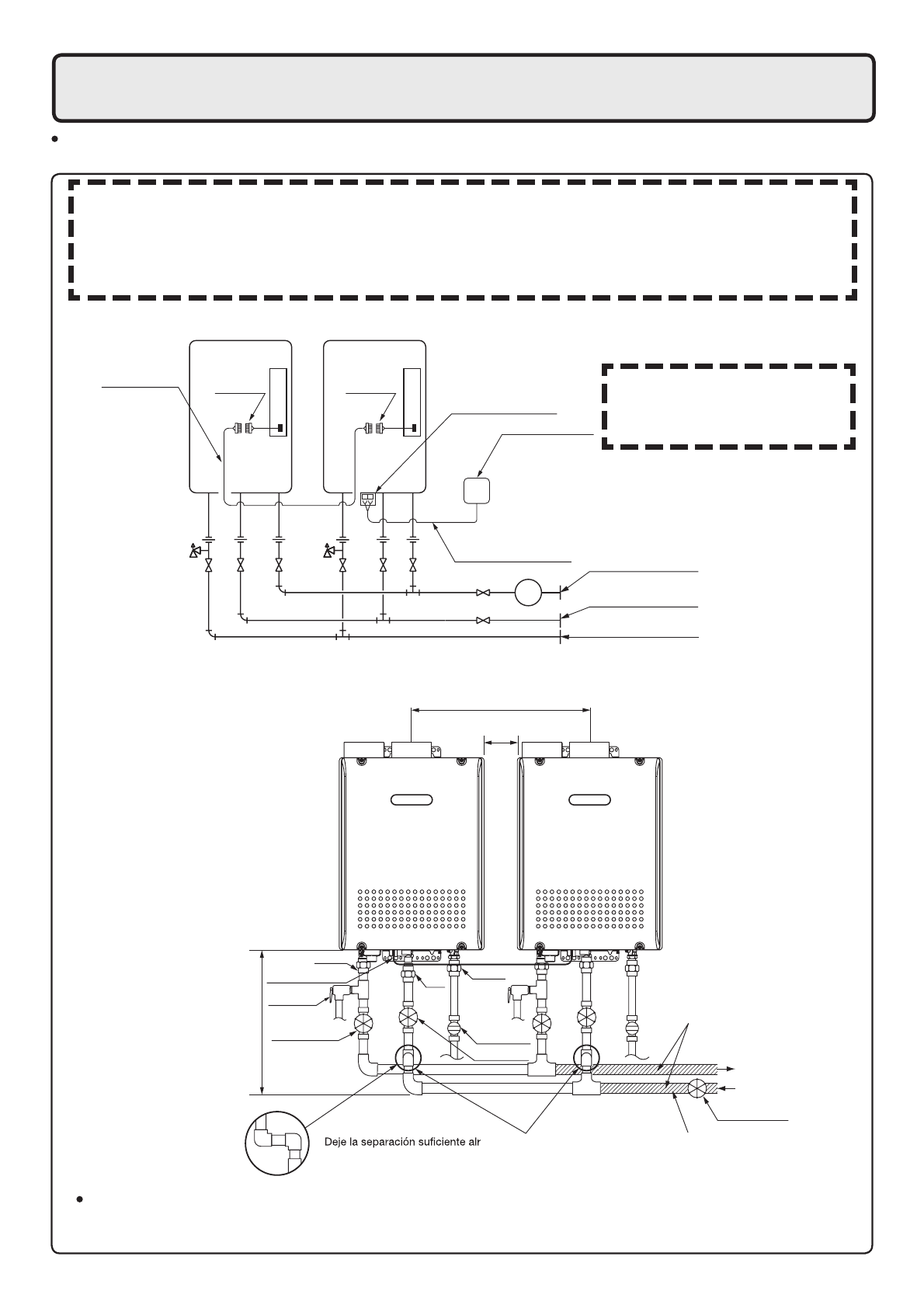
3
G
Cable de Conexión
Rápida
Cable del control remoto Tuberías de suministro
de gas
Suministro de agua fría
Agua caliente
Control remoto
Bloque de terminales
Conector
del cable
Conector
del cable
3. Instalación del Multi-sistema de Conexión Rápida
El multi-sistema de Conexión Rápida permite la instalación de dos unidades juntas usando
solamente el cable de conexión rápida.
Diagrama de plomería
* Al conectar dos unidades, utilice
solamente un control remoto.
Nota: Conecte el control
remoto solamente a
una de las unidades.
Diagrama del Sistema
Aisle las tuberías de agua caliente para evitar la pérdida de calor. Aísle y aplique materiales de
la calefacción a la tubería de agua fría para evitar la pérdida de calor y el congelamiento de las
tuberías cuando se expongan a temperaturas excesivamente frías.
Haga esta distancia lo más
corta posible.
* La temperatura del agua
caliente se volverá inestable
a medida que aumenta la
longitud de la tubería.
ededor de las
tuberías para aplicar el aislamiento. Será
necesario agregar recodos a las tuberías para
asegurar la existencia de esta separación
Se instala el desconector
antes que se diverge.
El cable de conexión rápida tiene 6 pies.(2m) de largo. Instale las unidades a 2-18" (50 -
457mm) de distancia una de otra
para asegurar que el cable se extienda por ambas unidades.
(Véa el diagrama Plomería).
(Si la distancia entre las dos unidades es demasiado grande, no sólo el cable no alcanzará,
sino que la temperatura del agua también puede volverse inestable debido a la diferencia en la
longitud de tubería entre las dos unidades).
Unión
Distancia en el centro 20.3 - 36.3 pulgadas. (515 - 922mm)
Cable de Conexión
Rápida
Unión
Válvula de gas
Unión
Válvula de cierre
Válvula de cierre
Agua caliente
Agua fría
Distancia a los lados
2 - 18 pulgadas. (50 - 457mm)
Ajuste las tuberías para permitir los
caudales máximos de las unidades.
Válvula de
alivio de presión
Válvula de cierre
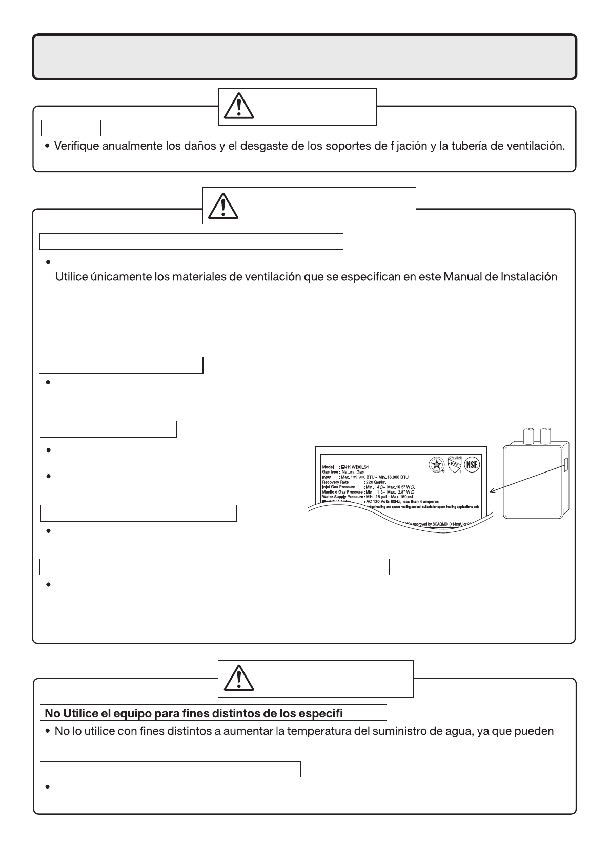
4
Comprobación del gas
Compruebe que la placa de características indica
el tipo correcto de gas.
Compruebe que la línea de suministro de gas
esté dimensionada para 199,900 Btuh.
Comprobación de la alimentación
La fuente de alimentación requerida es 120VAC, a 60Hz.
El uso de voltaje incorrecto puede provocar incendios o descargas eléctricas.
Tenga mucho cuidado si se utiliza con un precalentador solar
El uso de esta unidad con un precalentador solar puede dar lugar a temperaturas de salida
imprevisibles y posiblemente quemaduras. Si fuese absolutamente necesario, use válvulas
mezcladoras para garantizar que las temperaturas de salida no alcancen niveles de quemaduras.
No utilice un precalentador solar con el multi-sistema de conexión rápida.
4. Antes de la Instalación
Chequeo
Cámbielos si es necesario.
PELIGRO
cados
ocurrir accidentes inesperados.
Compruebe la calidad del suministro de agua
Si el suministro de agua es superior a 12 granos por galón (200 mg/L) de dureza, ácidez o impureza,
debe tratar el agua con métodos aprobados para asegurar la cobertura completa de la garantía.
ADVERTENCIA:
PRECAUCIÓN
Precauciones para cambiar la tubería de ventilación
El sistema de ventilación seguramente tendrá que ser cambiado cuando se instale este aparato.
para el uso de este aparato. Consulte la sección "Instalación de la Tubería de Ventilación" para más
detalles. Si el PVC, CPVC, o la tubería indicada en la Categoría IV ya está instalada, busque pinchazos,
grietas, o bloqueos y consulte con el fabricante de la tubería de ventilación antes de reutilizarla.
Una ventilación inadecuada puede provocar incendios, daños a la propiedad o la exposición al
monóxido de carbono.
Precauciones para la nieve
Si este producto es instalado en un área donde se conoce que la nieve se acumula, proteja la
terminación de la ventilación de la obstrucción por la acumulación de nieve o el daño de la nieve que
cae de los techos.
i

5. Elección del lugar de instalación
* Ubique el aparato en un área donde las fugas desde la unidad o las conexiones no provoquen daños
Coloque el terminal de ventilación para que no haya obstáculos alrededor de la terminación y para
que no se acumulen gases de escape. No envuelva la terminación con metal corrugado u otros
materiales.
en los que se usa gasolina, benceno y adhesivos, o lugares en que
ácidos).
El polvo puede bloquear la apertura del suministro de aire, provocando
la reducción del rendimiento del ventilador y por consiguiente una
combustión incompleta.
Como resultado pueden producirse fallos del encendido y averías.
interiores. Nunca lo instale en el exterior o en el baño, puede dañarse o
puede producirse un incendio.
Instale el calentador de agua en un área que permita las separaciones
apropiadas para la construcción combustible e incombustible.
Consulte la placa de características del aparato para las separaciones
apropiadas.
suministro y escape puedan instalarse como se indica.
en paredes exteriores o en materiales no resistentes al calor. También
tenga en cuenta los árboles y los animales circundantes.
El calor y la humedad del calentador de agua pueden causar la
decoloración de paredes y de materiales resinosos, o la corrosión de
los materiales de aluminio.
PELIGRO
ADVERTENCIA:
PRECAUCIÓN
Prohibido
Exterior
Prohibido
Peligro de intoxicación por monóxido de carbono. No instale este
calentador de agua en una caravana, en vehículos de recreo o en un
barco.
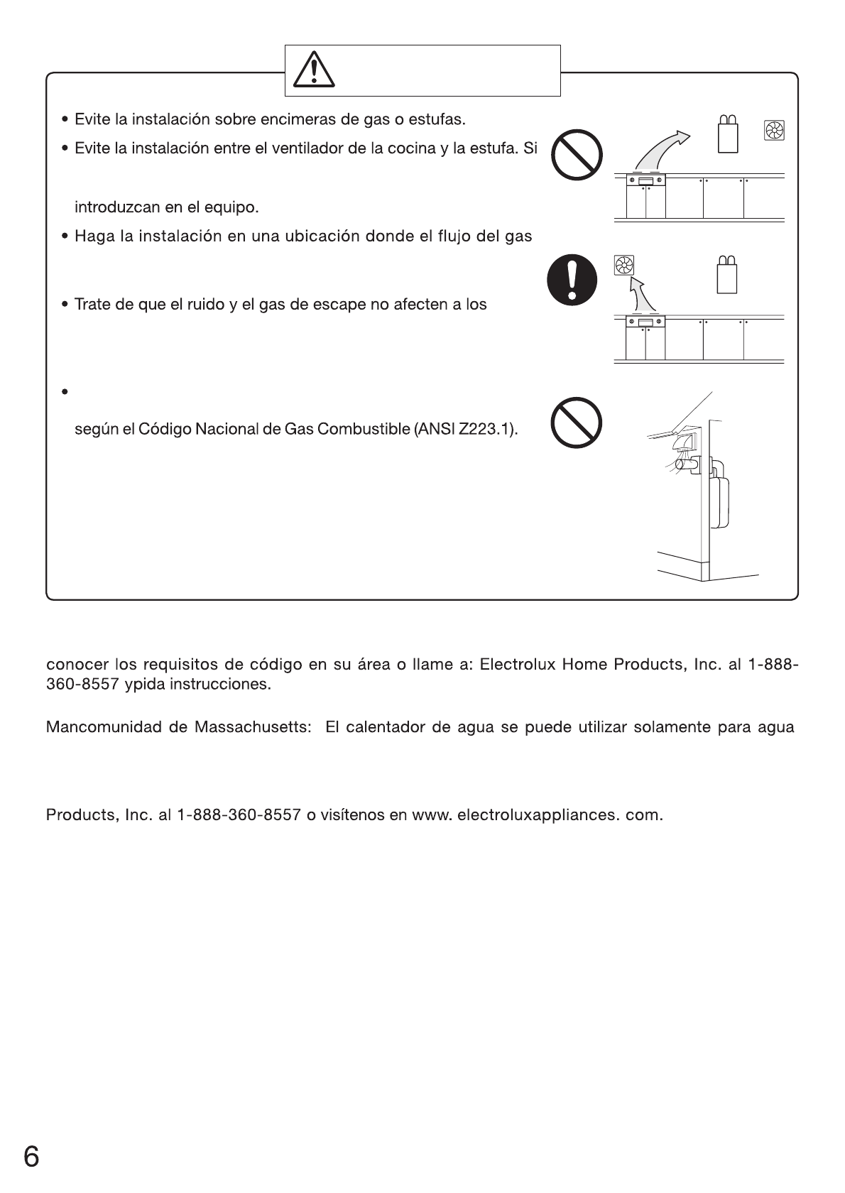
hay humo aceitoso o una gran cantidad de vapor en el lugar de
instalación, tome medidas para evitar que el humo y el vapor se
de escape no se vea afectado por ventiladores o campanas
extractoras.
vecinos. Evite la instalación en paredes comunes pues la
unidad hará algunos ruidos operacionales cuando esté en
funcionamiento.
Antes de hacer la instalación, cerciórese de que la terminación
de la chimenea de escape tendrá las separaciones apropiadas
Asegúrese de
hacerlo
Prohibido
Prohibido
PRECAUCIÓN
Estado de California: El calentador de agua debe estar asegurado, anclado o atado con correa para
evitar los movimientos durante un terremoto. Póngase en contacto con los servicios locales para
caliente y no en una combinación del agua doméstica y la calefacción.
Para información sobre los requisitos de los fabricantes de ventilación, llame a Electrolux Home
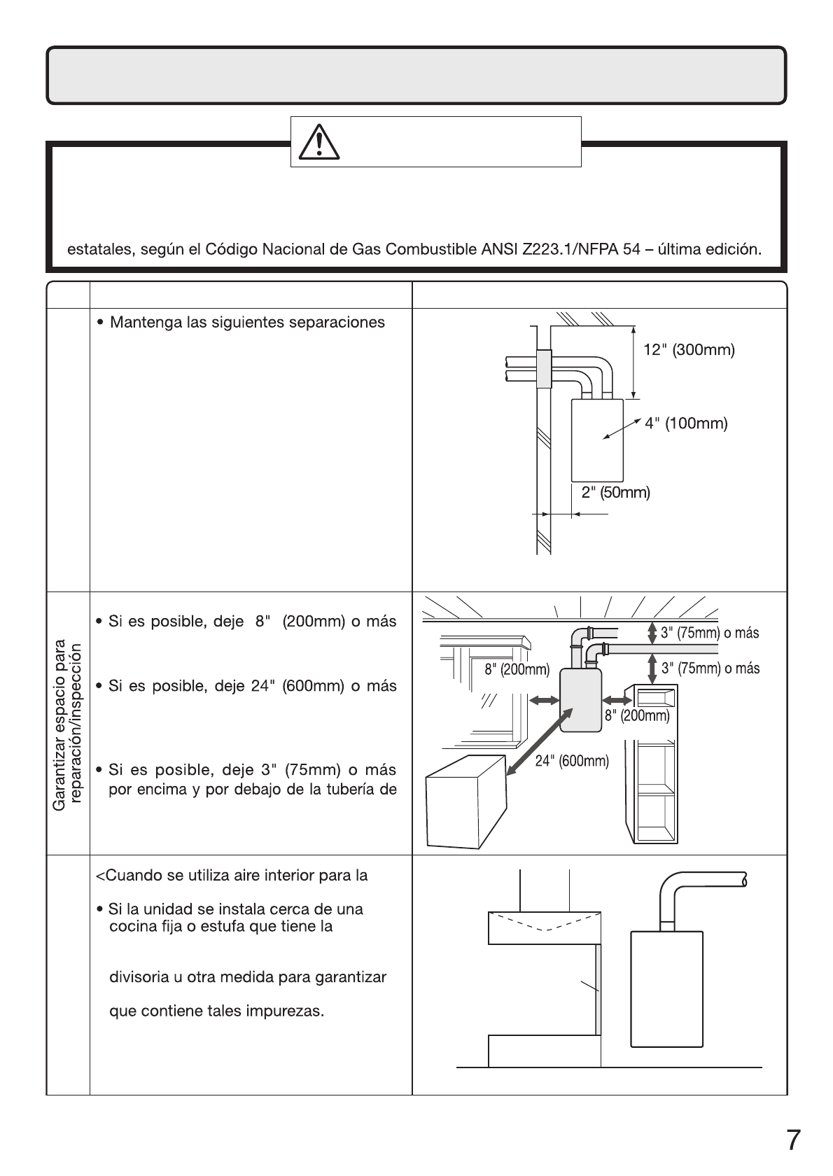
6. Separaciones en la instalación
Antes de hacer la instalación, compruebe lo siguiente:
Haga la instalación de acuerdo con los códigos de construcción y mecánicos correspondientes,
así como los reglamentos locales, estatales o nacionales, o en ausencia de códigos locales y
ADVERTENCIA:
Dato
Distancia desde los combustibles
para los materiales combustibles
e incombustibles
nóicartsulIraborpmoC
a
cualquier lado de la unidad para facilitar la
inspección.
al frente de la unidad para facilitar el
mantenimiento y la reparación si fuera
necesario.
ventilación para facilitar
la inspección y la
reparación si fuera necesario.
o más
Distancia desde
el lado
o más
o más
o más
o más
o más
combustión>
posibilidad de generar vapor que
contiene grasas o aceites, utilice la *placa
que la unidad no está expuesta al aire
* La placa divisoria debe ser de un material
incombustible con una anchura mayor
que el calentador de agua.
Campana de
extracción
Rango
Placa divisoria agua
calentador
Aparatos de cocina

8
SeparaciónRef
A=
Holgura por encima de desnivel, veranda, porche, cubierta o balcón
B=
Holgura hasta la ventana o puerta que podría abrirse
C=
Holgura para cerrar la ventana de forma permanente
D=
Holgura vertical para el plafón de ventilado situado encima del terminal
dentro de una distancia horizontal de 2 pies (61 centímetros) desde la
línea central del terminal
E=
Holgura hacia el plafón no ventilado
F=
Holgura hacia la esquina exterior
G=
Holgura de la esquina interior
H=
Holgura a cada lado de la línea central extendida por encima del
conjunto del contador/regulador
I=
Holgura hacia la salida del respiradero del regulador de servicio
J=
Holgura hacia la entrada de suministro de aire no mecánico al edificio
o la entrada de aire de combustión a cualquier otro aparato
K=
Holgura hacia una entrada de suministro de aire mecánico
L=
Holgura sobre la acera pavimentada o entrada pavimentada ubicada
en propiedad pública
Holgura por debajo de una veranda, porche, cubierta o balcón
M=
1 En conformidad con la norma vigente del Código de Gas Combustible Nacional ANSI Z223.1 / NFPA 54
* Holgura de acuerdo con los códigos de instalación locales y los requisitos del proveedor de gas.
La holgura hacia el muro contrario es de 24 pulgadas (60 cm).
12 pulgadas (30 cm)
*
*
*
*
*
*
*
*
3 pies (91 cm) por encima si está
dentro de 10 pies (3 m)
*
12 pulgadas (30 cm)
12 pulgadas (30 cm)
Instalaciones de
respiradero directas US 1
D
E
B
B
F
B
A
G
H
I
CB
M
K
J
B
B
L
A
Terminal de
ventilación
Entrada de
suministro de aire
Área donde no está
permitido el terminal
Requisitos de separación desde las terminaciones de ventilación hasta los canales.
<Al suministrar aire de combustión desde el exterior (Respiradero directo)>
* Todos los requisitos de separación cumplen las normas ANSI Z21.10.3 y el Código Nacional de
Gas Combustible, ANSI Z223.1.
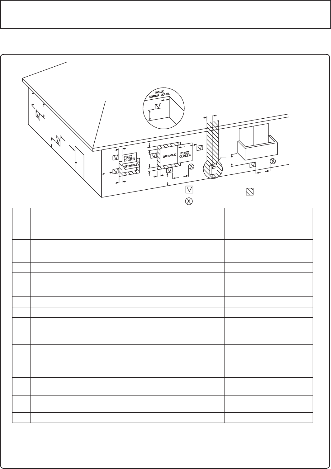
9
*
*
*
*
*
*
*
*
3 pies (91 cm) por encima si está dentro
de 10 pies (3 m) horizontalmente
*
4 pies (1.2 m) más abajo o
hacia el lado de apertura;
1 pie (30 cm) por encima de la apertura
4 pies (1,2 m) más abajo o
hacia el lado de apertura;
1 pie (30 cm) por encima de la apertura
SeparaciónRef
A=
Holgura por encima de desnivel, veranda, porche,
cubierta o balcón
B=
Holgura hasta la ventana o puerta que podría abrirse
C=
Holgura para cerrar la ventana de forma permanente
D=
Holgura vertical para el plafón de ventilado situado encima del terminal
dentro de una distancia horizontal de 2 pies (61 centímetros) desde la
línea central del terminal
E=
Holgura hacia el plafón no ventilado
F=
Holgura hacia la esquina exterior
G=
Holgura de la esquina interior
H=
Holgura a cada lado de la línea central extendida por encima del
conjunto del contador/regulador
I=
Holgura hacia la salida del respiradero del regulador de servicio
J=
Holgura hacia la entrada de suministro de aire no mecánico al edificio
o la entrada de aire de combustión a cualquier otro aparato
K=
Holgura hacia una entrada de suministro de aire mecánico
L=
Holgura sobre la acera pavimentada o entrada pavimentada ubicada
en propiedad pública
Holgura por debajo de una veranda, porche, cubierta o balcón
M=
1 En conformidad con la norma vigente del Código de Gas Combustible Nacional ANSI Z223.1 / NFPA 54
* Holgura de acuerdo con los códigos de instalación locales y los requisitos del proveedor de gas.
La holgura hacia el muro contrario es de 24 pulgadas (60 cm).
12 pulgadas (30 cm)
Instalaciones de
respiraderos indirectas US 1
D
E
B
B
F
B
A
G
H
I
CB
M
K
J
B
B
L
A
Terminal de
ventilación
Entrada de
suministro de aire
Área donde no está
permitido el terminal
Requisitos de separación desde las terminaciones de ventilación hasta los canales.
<Al suministrar aire de combustión desde el interior (Respiradero indirecto)>
* Todos los requisitos de separación cumplen las normas ANSI Z21.10.3 y el Código Nacional de
Gas Combustible, ANSI Z223.1.
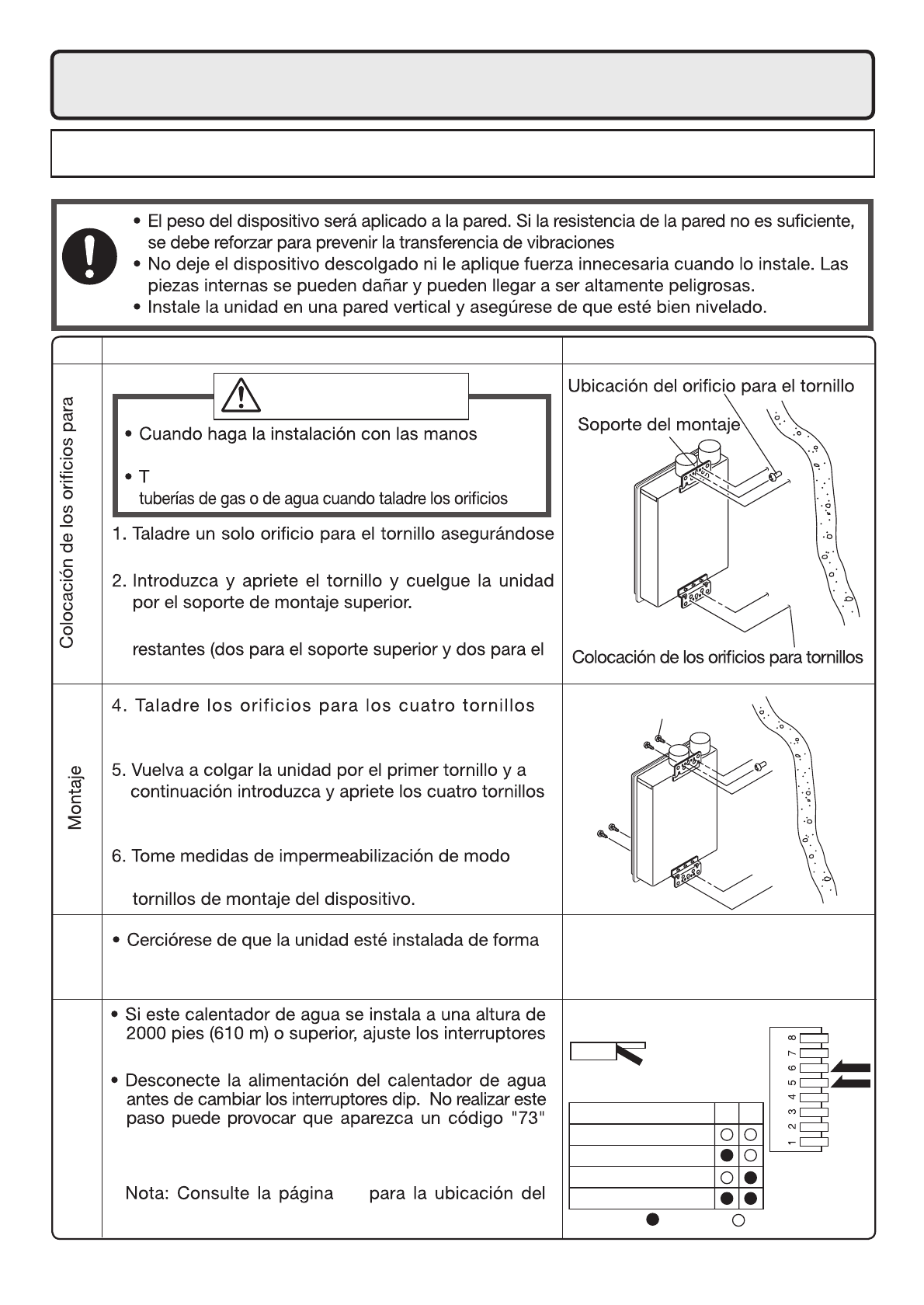
10
7. Instalación
Fijación en la pared
Ilustración
Comprobar
restantes.
restantes.
que el agua no entre en el inmueble a través de los
segura de modo que no se caiga o se mueva a
causa de vibraciones o terremotos.
de perforar un travesaño.
3. Determine las posiciones para los cuatro tornillos
inferior), y quite la unidad.
tornillos
Estructura
desnudas, tome precauciones para no lesionarse.
enga cuidado de no golpear el cableado eléctrico, las
Dato
PRECAUCIÓN
Asegúrese de
hacerlo
superior
Instalaciones en elevaciones
sobre los 2,000 pies.
dip como se ilustra en la tabla a la derecha.
en el control remoto y se detenga el funcionamiento.
Si esto ocurre, desconecte y vuelva a conectar el
calentador de agua para restablecer el sistema.
banco de interruptores dip.
31
* No cambie ninguno de los interruptores.
ENCENDIDO
APAGADO
* Ajuste de elevación alta.
65
2,001 - 4,000 pies (611 - 1,220m)
0 - 2,000 pies (0 - 610m)
4,001 - 6,000 pies (1,221 - 1,830m)
6,001 - 8,000 pies (1,831 - 2,440m)
ENCENDIDO= APAGADO=
Comprobar
Comprobar
Comprobar
Comprobar
Tornillo de jación

11
Llenado del purgador de condensado con agua
El purgador de condensado se puede llenar antes de conectar la tubería de ventilación.
Llenado del purgador de condensado antes de la instalación de la tubería de ventilación.
PELIGRO
Antes del arranque inicial, cerciórese de llenar el purgador de condensado
con agua.
Esto es para evitar que gases de escape peligrósos entren en el inmueble.
No llenar el purgador de condensado puede provocar lesiones personales
graves o la muerte.
Siga uno de los procedimientos descritos a continuación para asegurar que el purgador de condensado
esté lleno de agua.
de escape en la parte superior del aparato como se ilustra a continuación.
O, si ya se ha instalado la tubería de ventilación:
2)
Después de instalar la tubería de desagüe, cerciórese de que el área alrededor del aparato esté bien
Ventilada; si es necesario, abra una ventana o una puerta.
tubería de desagüe.
instalación, puede tardar más).
Nota: El condensado descargado del calentador de agua tiene un nivel del pH de aproximadamente
27-28
Entrada
Escape
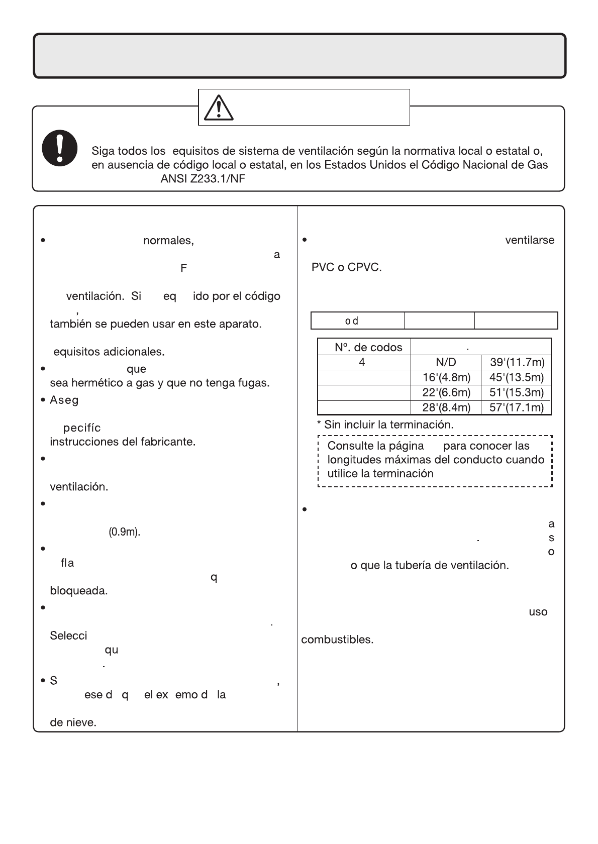
12
Longitudes máximas de ventilación
Este aparato ha sido diseñado para
con 3" (75 mm) o 4" (100 mm) de tubería de
No exceda las siguientes longitudes máximas de
ventilación:
Mantenga el mismo diámetro de la tubería
16
TWHHORCONC.
de ventilación desde la chimenea hasta l
terminación de la ventilación Las tubería
de escape y entrada deben tener el mism
diámetr
8. Instalación de la Tubería de Ventilación
ADVERTENCIA:
Asegúrese de
hacerlo
INTOXICACIÓN POR MONÓXIDO DE CARBONO
r
Combustible PA 54 – última edición
Longitud máx de ventilación recta*
Diámetr e la tubería
3" (75mm) 4"(100mm)
Bajo condiciones este aparato no
producirá una temperatura en la chimene
de escape mayor de 149° (65°C) y la tubería
PVC cedula 40 puede usarse como material
de es r uer
local las tuberías CPVC cedulas 40 u 80
Consulte la página 14 para conocer los
r
Cerciórese de el sistema de ventilación
ure la tubería de ventilación con
soportes a intervalos regulares según se
es a en estas instrucciones o las
No utilice ventilación compartida o conecte
más de un aparato a este sistema de
La longitud total de la ventilación incluyendo las
conexiones horizontales y verticales no debe ser
menor de 3'
No almacene sustancias peligrosas o
in mables cerca de la terminación de
la ventilación y compruebe ue no esté
La terminación de la ventilación puede
expulsar vapor o agua condensada
one la ubicación para la terminación
de modo e se eviten lesiones o daños
materiales
i se pronostica acumulación de nieve
asegúr e ue tr e tubería no
esté cubierta de nieve o golpeada por trozos
Requisitos Generales
Separaciones
El PVC o CPVC ha sido aprobado para el
en este aparato con separación cero a los
3
2
1

13
13
24
Longitud corta usando una tubería
de 4" (100mm)
Longitud corta usando una
tubería de 3" (75mm)
Longitud larga usando una
tubería de 3" (75mm)
Longitud larga usando una tubería
de 4" (100mm)
**En la tabla se asume que las piezas rectas de ventilación son
de 3’ (0.9m) cada una.
También se pueden usar piezas de ventilación más cortas o más largas
hasta la longitud máxima permitida.
* No cambie ninguno de los interruptores.
* Consulte la página 16 para conocer las longitudes
máximas del conducto cuando utilice la terminación
TWHHORCONC.
ENCENDIDO
APAGADO
La alimentación debe estar desconectada
cuando se ajusten los interruptores dip
para cambiar la cantidad de f ujo de aire.
La unidad se puede ajustar para acomodar conexiones de ventilación más largas; consulte la
siguiente tabla para ver la longitud máxima de ventilación basada en la cantidad de codos. Ajuste los
interruptores dip según la condición de la ventilación indicada en las siguientes tablas.
Nota: con un caño de 3" (75mm)" Cuando se ajusten los interruptores dip para conexiones de
ventilación más largas, la entrada de BTUH del aparato se reducirá hasta un 5%.
Interruptores de ajustes de longitudes máximas de ventilación
[Ejemplo de longitudes máximas de ventilación]
Desconecte la alimentación del calentador de agua antes de cambiar los interruptores dip.
No realizar
este paso puede provocar que aparezca un código "73" en el control remoto y se
detenga el funcionamiento
. Si esto ocurre, desconecte y vuelva a conectar el calentador de
agua para restablecer el sistema.
Nota: Consulte la página 31 para la ubicación del banco de interruptores dip.
- Dos ductos de 90°, longitud máxima = 3 pies (0.9 m) (con interruptores
- Dos ductos de 90°, longitud máxima = 51 pies (15.3 m) (con interruptores
0
3
6
9
12
15
16
18
21
22
24
27
28
30
33
34
0.00
0.90
1.80
2.70
3.60
4.50
4.80
5.40
6.30
6.60
7.20
8.10
8.40
9.00
9.90
10.20
m 10 2 3pies
Longitud de ventilación Longitud de ventilación
3” Pipe
Codos
0
1
2
3
4
5
6
6
7
8
8
9
10
10
11
12
Cantidad de
piezas** Cantidad de
piezas**
1
1
0%
0%
-5%
-5%
1
1
1
1
2
2
2
2
2
2
2
2
2
2
1
1
0%
0%
-5%
-5%
1
1
2
2
2
2
2
2
2
2
2
1
1
0%
0%
-5%
-5%
2
2
2
2
2
2
2
2
0%
-5%
2
2
2
2
2
2
2
* Sin incluir la terminación.
0
3
6
9
12
15
18
21
24
27
30
33
36
39
42
45
48
51
54
57
60
63
0.00
0.90
1.80
2.70
3.60
4.50
5.40
6.30
7.20
8.10
9.00
9.90
10.80
11.70
12.60
13.50
14.40
15.30
16.20
17.10
18.00
18.90
m 10 2 3 4
Codos
0
1
2
3
4
5
6
7
8
9
10
11
12
13
14
15
16
17
18
19
20
21
3
3
0%
-3%
-3%
-5%
3
3
3
3
3
3
3
3
3
4
4
4
4
4
4
4
4
4
4
4
3
3
0%
-3%
-3%
-5%
3
3
3
3
3
3
3
4
4
4
4
4
4
4
4
4
4
4
3
3
0%
-3%
-3%
-5%
3
3
3
3
3
4
4
4
4
4
4
4
4
4
4
4
3
3
0%
-3%
-3%
-5%
3
3
3
4
4
4
4
4
4
4
4
4
4
4
3
3
0%
-3%
-3%
-5%
3
4
4
4
4
4
4
4
4
4
4
4
4” Pipe
* Sin incluir la terminación.
pies
Longitud corta usando una
tubería de 4" (100mm)
Longitud corta usando una
tubería de 3" (75mm)
Longitud larga usando una
tubería de 3" (75mm)
Longitud larga usando una
tubería de 4" (100mm)
* Condición de longitud de ventilación.
1
7 8
2
3
4
Comprobar
Comprobar
Comprobar
Comprobar
ENCENDIDO= APAGADO=
l
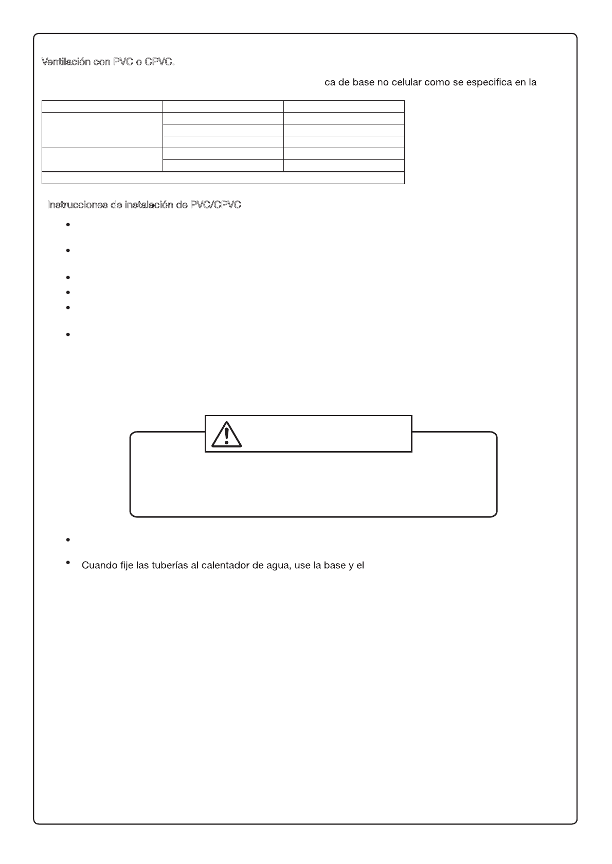
14
ADVERTENCIA
INTOXICACIÓN POR MONÓXIDO DE CARBONO
Artículo Material Estados Unidos
Escape/entrada de aire
PVC cedula 40 ANSI/ASTM D1785
PVC-DWV ANSI/ASTM D2665
CPVC cedula 40 ANSI/ASTM F441
Cemento/base de la tubería PVC ANSI/ASTM D2564
CPVC ANSI/ASTM F493
Nota: No use tuberías de base de espuma celular
Instrucciones de instalación de PVC/CPVC
Siga normas generales de ventilación según se describe en esta página.
La tubería se instalará de forma tal que las primeras 3’ (0.9m) de chimenea queden accesibles para la
inspección visual.
Cuando prepare y ensamble la tubería, siga las instrucciones suministradas por el fabricante. En general,
se deben cumplir las siguientes prácticas:
o Corte en ángulo recto todas las piezas de tubería.
o Quite las rebabas y desechos de las juntas y accesorios.
o Todas las juntas se deben limpiar, cebar y cementar adecuadamente. Solamente use cemento y
base aprobados para su uso en tuberías según se describe en la tabla anterior.
El PVC o CPVC ha sido aprobado para el uso en este aparato con separación cero a los combustibles.
La tubería cedula 80 de 3" o 4" también se puede usar en este aparato, sin embargo la entrada BTUH del
aparato se reducirá en un 5%.
Ventilación con PVC o CPVC.
No sellar adecuadamente el sistema de ventilación puede
provocar que los productos de la chimenea entren en la
vivienda.
cemento adecuados para asegurar un se
quede bien sellado.
Todas las tuberías deben estar totalmente aseguradas. Use soportes a intervalos mínimos de 3’ (0.9m).
No use el calentador de agua para asegurar las tuberías de ventilación.
Este aparato se puede ventilar con materiales de tubería plásti
siguiente tabla.
Use solamente tuberías sólidas PVC o CPVC cedula 40 La tubería de base de espuma celular no está
permitida.
BDebe instalarse una rejilla antipájaros en las terminaciones del respiradero si es que no forma ya parte del
conjunto de terminación del respiradero para evitar que la suciedad o los animales penetren en la tubería.
Estas rejillas no se proporcionan con el calentador de agua y se deben comprar por separado.

15
Terminación de la ventilación vertical- solo materiales PVC/CPVC
B
B
B
B
B
B
B
B
B
Terminación de la ventilación horizontal- solo materiales PVC/CPVC
B
B
B
B
B
B
B
B
Como se ilustra a la izquierda, cerciórese de mantener una distancia de 3' (0.9m)
o más entre la entrada y el escape cuando instale las tuberías de ventilación.
*
Si no puede asegurarse una distancia de 3’ (0.9 m) entre la
admisión y el escape, la instalación puede realizarse únicamente
siguiendo el método de instalación que aparece en la página 17.
La terminación TWHHORHOOD puede utilizarse en lugar de los codos
como terminaciones del respiradero horizontales. No es necesario
utilizar rejillas antipájaros con la terminación TWHHORHOOD. Vea
página 17 para más información.
Hacer la terminación el menos a 12" (300mm) por encima del
nivel del piso o por encima de la línea de nieve.
Hacer la terminación al menos a 7' (2.1m) por encima de vías
públicas, a 6' (1.8m) de la entrada de aire de combustión de
cualquier aparato y a 3' (0.9m) de otros canales, del contador
de gas, regulador de reparación, etc.
Hacer la terminación el menos a 3' (0.9m) por encima de cualquier
entrada de aire forzado dentro de 10' (3m) , 1' (0.3m) por debajo,
1' (0.3m) horizontalmente o a 1' (0.3m) por encima de cualquier
puerta, ventana o entrada de aire por gravedad en cualquier inmueble
según el Código Nacional de Gas Combustible ANSI Z233.1/NFPA 54.
Incline la ventilación horizontal 1/4" hacia arriba cada 12" (300mm)
en dirección de la terminación.
Use un desagüe de condensación si es necesario.
En la Mancomunidad de Massachusetts es obligatorio utilizar un detector de
monóxido de carbono para todos los equipos de gas con ventilación horizontal.
Consulte el boletín técnico TB 010606 para conocer todas las instrucciones de
instalación.
Cuando elija las terminaciones de entrada y escape, debe usar el
mismo tipo de codo (es decir dos codos de 90°).
Esto ayuda a obtener una combustión apropiada poniendo ambas
terminaciones en la misma zona de presión.
Como se ilustra a la izquierda, cerciórese de mantener una
distancia de 3' (0.9m) o más entre la entrada y el escape
cuando instale las tuberías de ventilación.
La terminación TWHVERTCAP puede utilizarse en lugar de
los codos como terminación del respiradero vertical. No es
necesario utilizar rejillas antipájaros con la terminación
TWHVERTCAP.
Hacer la terminación al menos a 6' (1.8m) de la entrada de
aire de combustión de cualquier aparato y a 3' (0.9m) de otros
canales, del co ntador de gas, regulador de servicio, etc.
Coloque los sistemas de ventilación externa debajo de la
línea del techo para limitar la condensación y proteger
contra fallos mecánicos.
Cuando la ventilación entra en un piso o techo y no
atraviesa un conducto a prueba de incendios, es obligatorio
poner un cortafuegos y un soporte.
Cuando la terminación de la ventilación está ubicada a no
menos de 8' (2.4m) de la pared vertical u otra obstrucción,
haga la terminación por encima del techo al menos a 2'
(0.6m), pero no más de 6' (1.87m), según el Código
Nacional de Gas Combustible ANSI Z233.1/NFPA 54.
Coloque soportes verticales cada 3' (0.9m) o a la distancia
indicada en las instrucciones de fabricante de la tubería de
ventilación.
Se recomienda una pequeña sección horizontal para evitar
que los desechos caigan en el calentador de agua.
Cuando use una sección horizontal, incline la ventilación
horizontal 1/4” hacia arriba cada 12" (300mm) en dirección
de la terminación del desagüe.
Cuando elija las terminaciones de entrada y escape, debe usar el
mismo tipo de codo (es decir dos codos de 90°).
Esto ayuda a obtener una combustión apropiada poniendo ambas
terminaciones en la misma zona de presión.
Correas
para colgar
**Se recomienda 1' como mínimo,
pero no es obligatorio.
* No proporcionado con el calentador
de agua, ordenar por separado.
**1'
Mínimo
Incline la
ventilación
hacia arriba
Entrada
Escape
Introduzca la rejilla
antipájaros* en el
extremo del codo
de 90
3” Min.
3 pies. Min.
CortafuegosCortafuegos
cortafuegos/soporte
Tapajuntas
de techo
Tapajuntas
de techo
Correas
para colgar
**1'
mínimo
Soporte
Incline la ventilación
hacia arriba
Entrada Escape
12" por encima del
nivel de nieve máximo
o 24", el que sea mayor.
12" por encima
del nivel de
nieve máximo
o 24", el que
sea mayor.
Introduzca la
rejilla antipájaros*
en el extremo
del codo de 90
Collar de
tormenta
Collar de
tormenta
**Se recomienda 1' como mínimo,
pero no es obligatorio.
*
No proporcionado con el
calentador de agua, ordenar
por separado.
Introduzca la
rejilla antipájaros*
en el extremo
del codo de 90
Instalación de la tubería de ventilación
B
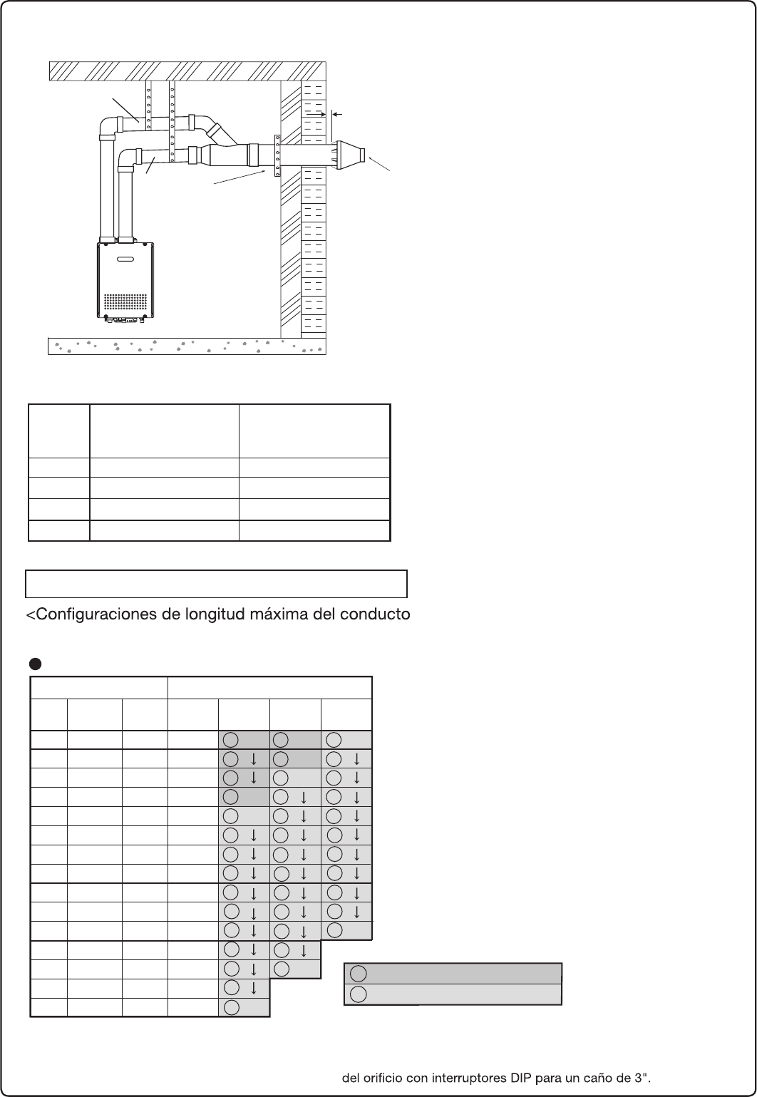
16
5
5
5
5
5
5
5
Terminación de la ventilación horizontal - 3" (75m) Terminación concéntrica PVC/CPVC
5
5
5
5
5
Correas para
colgar
Entrada de 3"
(75mm) o de 4"
(100mm)*
Escape de 3"
(75mm) o de 4"
(100mm)*
Incline la
ventilación
hacia arriba
* En la tubería de 4" (100mm) es necesario usar un
cople de reducción justo antes de la terminación.
1" (25mm) to
4" (100mm)
Introduzca la rejilla
antipájaros ***
en el extremo de la
terminación
Correas
** Sin incluir la terminación
*** No proporcionado
con el calentador
de agua, ordenar
por separado.
Cantidad
de codos
3
2
1
4
PVC o CPVC de 3" (75mm)
Longitud máx. de
ventilación recta**
PVC o CPVC de 4" (100mm)
Longitud máx. de
ventilación recta**
16' (4.8m)
N/D
22' (6.6m)
28' (8.4m)
30' (9.0m)
N/D
36' (10.8m)
42' (12.6m)
*** Consulte la página 13 ver la tabla de Ajuste de longitud máxima
3
4
longitud corta con un caño de 4" (100mm)"
longitud larga con un caño de 4" (100mm)"
****La tabla asume que las piezas del conducto recto tienen 3’ (0.9 m) cada una.
Las piezas del conducto más cortas o más largas también podrían utilizarse
hasta la longitud máxima permitida del conducto.
Ajuste de longitud máxima del conducto con interruptores DIP.
0
3
6
9
12
15
18
21
24
27
30
33
36
39
42
0.00
0.90
1.80
2.70
3.60
4.50
5.40
6.30
7.20
8.10
9.00
9.90
10.80
11.70
12.60
m 10 2 3pies
Longitud de ventilación***
y entrada reducida>
Codos
0
1
2
3
4
5
6
7
8
9
10
11
12
13
14
N/D
N/D
N/D
N/D
N/D
N/D
$/5+'$''(
1+(:$4
F%5;1
!-?@.1=I-01%*:%*0188:
88 >1 ;@101 @>-= 19?1=859-/5:91>/:9/H9?=5/->
"-9?193- 17 85>8:05G81?=:01 7- ?@.1=I-01
A19?57-/5K9 01>01 7-/458191- 4->?-7- ?1=859-/5K9
#:1B/10-7->7:935?@01>8GB58->01A19?57-/5K9
>13L9>11>;1/5N/-191>?->1//5K9
@-90:@>1@9-?@.1=I-0188>1=G
91/1>-=5:@>-=/:;71>01=10@//5K901
88B88C@9-;1<@1J->1//5K901
?@.1=I- 01 88 ;-=-/:91/?-= 7- ?1=859-/5K9
)>1@9->1//5K901?@.1=I-019:8G>01
88;-=-4-/1=7-/:91B5K919?=17:>/:;71>
01=10@//5K9C7-?1=859-/5K9
1.14-.1=@9->1;-=-/5K90188-
8819?=17-;-=101B?1=5:=C7->1//5K901
19?=-0-01-5=1197-?1=859-/5K9/:8:>157@>?=-
-7-5D<@51=0-
9>?-71@9-/:==1-01>13@=50-0;-=-1A5?-=
8:A58519?:>197-?1=859-/5K9
-/1=7-?1=859-/5K917819:>-88;:=
19/58-01795A17017;5>::;:=19/58-017-7I91-
01951A1
-/1=7-?1=859-/5K9-7819:>-E8;:=
19/58-01AI->;L.75/->-E8017-19?=-0-
01-5=101/:8.@>?5K901/@-7<@51=-;-=-?:C-E
801:?=:>/-9-71>017/:9?-0:=013->
=13@7-0:=01>1=A5/5:1?/
-/1=7-?1=859-/5K917819:>-E8;:=
19/58-01/@-7<@51=19?=-0-01-5=12:=D-0:
019?=:01E8E8;:=01.-6:E
84:=5D:9?-7819?1:-E8;:=19/58-
01/@-7<@51=;@1=?-A19?-9-:19?=-0-01-5=1;:=
3=-A10-0 19 /@-7<@51= 598@1.71 >13L9 17 K053:
#-/5:9-7 01 -> :8.@>?5.71#' ,#%
9/75917-A19?57-/5K94:=5D:9?-74-/5--==5.-
/-0-88
)>1 @9 01>-3M1 01 /:9019>-/5K9 >5 1> 91/1>-=5:
97-"-9/:8@950-001"->>-/4@>1??>1>
:.753-?:=5:@?575D-=@901?1/?:=018:9KB50:01
/-=.:9:;-=-?:0:>7:>1<@5;:>013->/:9
A19?57-/5K94:=5:9?-7
:9>@7?117.:71?I9?H/95/:(;-=-
/:9:/1=?:0->7->59>?=@//5:91>0159>?-7-/5K9
!-?1=859-/5K9/:9/H9?=5/-(+$&$#
;:0=I--/:=?-=>1;1=:9:-7-=3-=>1/:9=1>;1/?:-
>@7:935?@0:=5359-7>@8595>?=-0-012G.=5/-
!-?1=859-/5K9/:9/H9?=5/->:7:;@101@>-=>119
?1=859-/5:91>4:=5D:9?-71>
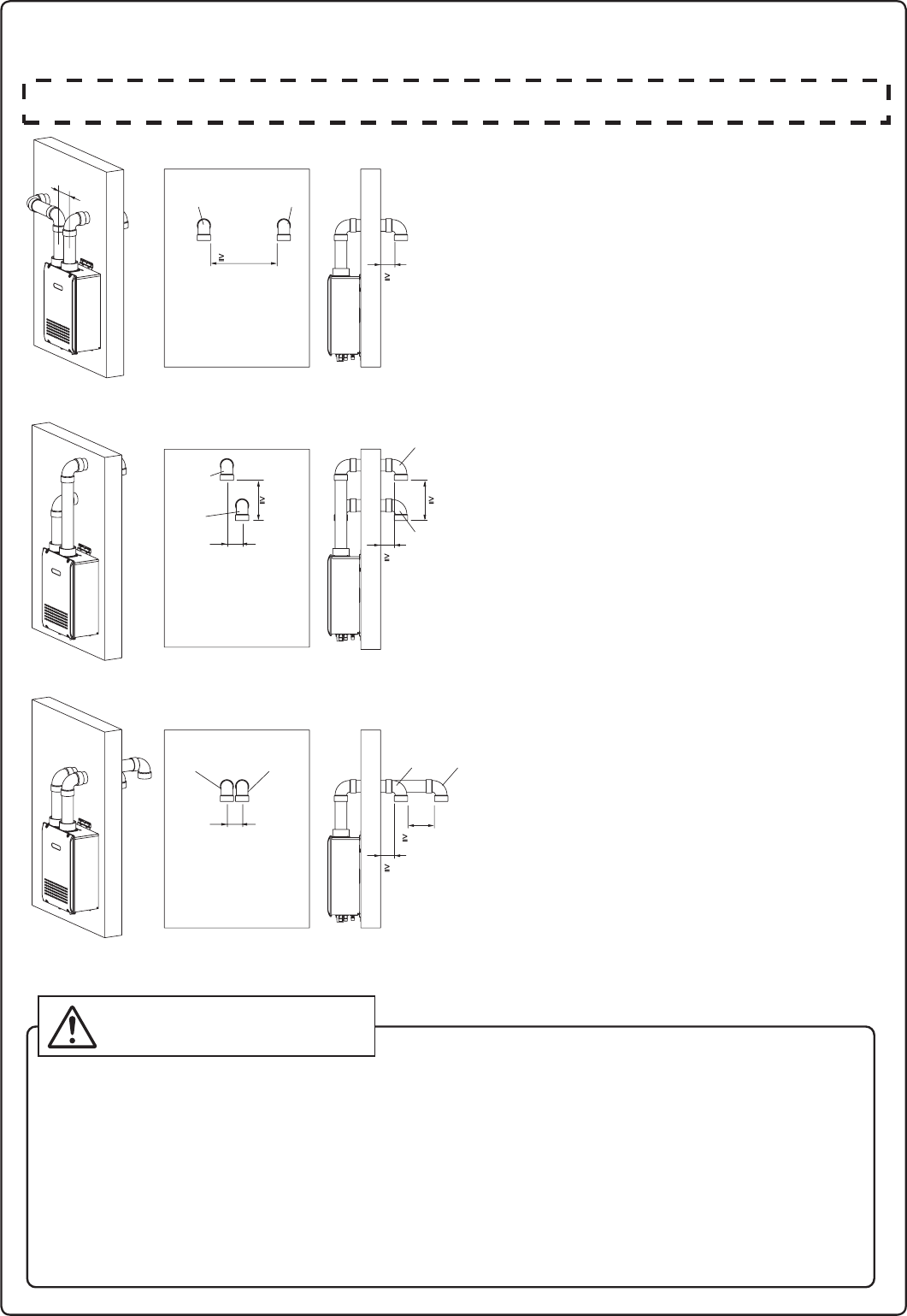
17
Instalación de la tubería de ventilación
Terminación de la ventilación horizontal- solo materiales PVC/CPVC
La entrada y el escape deben estar orientados en la
misma dirección.
La entrada y el escape deben mantener la misma
zona de presión.
No utilice TWHHORHOOD como una terminación del respiradero a menos que haya 3 pies. (0.9 m) o más de distancia entre el tubo de admisión y el tubo de escape.
Las instalaciones donde no puedan cumplirse 3 pies (0,9 m) de distancia, use codos de 90 ° como terminaciones del respiradero tal y como se muestra en las siguientes ilustraciones.
2pies. Min
Vista interior
Vista interior Vista exterior
Vista interior Vista exterior
1pies. Min1pies. Min
2
Introduzca la rejilla antipájaros.
A 90° del ajuste vertical del codo (hacia abajo).
2
Asegúrese que haya una distancia de al menos 3 pies (0.9m) o
más entre el borde cercano de la tubería de entrada de aire o de
la tubería de escape hasta el interior de la esquina de la pared.
2
Asegúrese que haya una distancia de al menos 2 pies (0.6m)
o más entre la tubería de entrada y la de escape.
La distancia se mide por dentro de la tubería para
la dimensión interna.
2
La entrada y el escape deben estar orientados en la
misma dirección.
La entrada y el escape deben mantener la misma
zona de presión.
2
Introduzca la rejilla antipájaros.
A 90° del ajuste vertical del codo (hacia abajo).
2
Asegúrese que haya una distancia de al menos 3 pies (0.9m)
o más entre el borde de la tubería de entrada
de aire o la tubería de escape y la esquina de la pared.
2
Arriba está el escape y debajo la entrada.
La conexión a la inversa no está permitida.
2
Asegúrese que haya una distancia de al menos 1pie (0.3m)
o más entre la tubería de entrada y la de escape.
La distancia se mide en las salidas del puerto de
entrada (terminal) y del puerto de escape (terminal).
2
La entrada y el escape deben estar orientados en
la misma dirección.
La entrada y el escape deben mantener la misma
zona de presión.
3
Introduzca la rejilla antipájaros.
A 90° del ajuste vertical del codo (hacia abajo).
3
Asegúrese que haya una distancia de al menos 3 pies (0.9m)
o más entre el borde de la tubería de entrada de aire o la
tubería de escape y la esquina de la pared.
3
El lado alejado de la pared es la entrada, el lado
cerca de la pared es el escape.
La conexión a la inversa no está permitida.
3
Asegúrese que haya una distancia de al menos 1
pie
(0.3m)
o más entre la tubería de entrada y la de escape.
La distancia se mide por dentro de la tubería para
la dimensión interna.
3
3
Escape
Entrada
Escape Entrada
1pies. Min
Vista exterior
Escape
Escape
Entrada
Entrada
Escape Entrada
3” Min
ADVERTENCIA
Si la distancia entre las terminaciones de entrada de aire y el escape es muy corta, el calentador
de agua atraerá los gases de escape a través de la entrada. Hay riesgos de entrada
de aire de combustión en el calentador de agua, aumentando las emisiones de Monóxido de
Carbono (CO) y de ruido debido a la vibración.
3
3No está permitido invertir las tuberías de entrada de aire y escape.
Aumentarán las emisiones de Monóxido de Carbono (CO) y el ruido debido a la vibración.
3” Min
3” Min
5.9”
5.9”
5.9”
Los codos de terminación deben estar orientados verticalmente, apuntando directamente hacia
abajo. Intentar evitar que el aire de escape se introduzca por la entrada de aire cambiando de
posición los codos de terminación aumentará el riesgo de congelación.
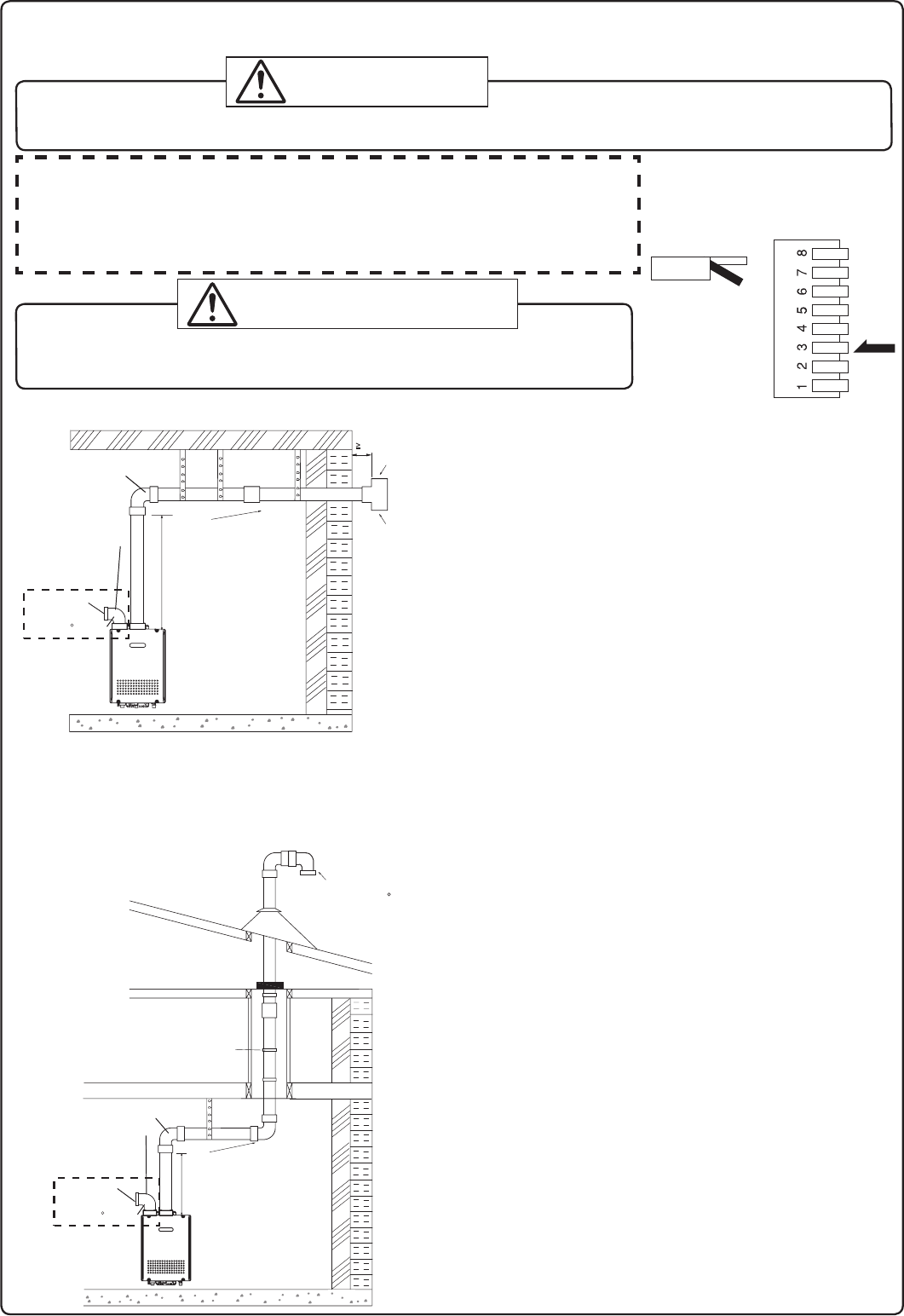
18
Terminación de la ventilación vertical- solo
materiales PVC/CPVC
Cortafuegos
cortafuegos/soporte
Tapajuntas
de techo
Collar de
tormenta
Correas
para colgar
Terminación de la ventilación horizontal- solo materiales PVC/CPVC
Correas para
colgar
**1' (0.3m) mínimos
Incline la
ventilación
hacia arriba
**Se recomienda 1' como
mínimo, pero no es obligatorio.
* No proporcionado con el
calentador de agua, ordenar
por separado.
Soporte
* No proporcionado con el
calentador de agua, ordenar
por separado.
**1' (0.3m)
Mínimo
**Se recomienda 1' como(0.3m)
mínimo, pero no es obligatorio.
<
<
<
<
<
<
<
D
D
D
D
D
D
D
D
Escape
Entrada
Escape
Entrada
90 Codo
Accesorio Kit de
conversión SV
(#SV-CK-3)
90 Codo
Accesorio Kit de
conversión SV
(#SV-CK-3)
Incline la
ventilación
hacia arriba
Filtro de entrada
Filtro de entrada
3” Min.
Un soporte, un codo de 90°, o la terminación TWHHORHOOD
podría utilizarse para la terminación del respiradero. No es necesario
utilizar rejillas antipájaros con la terminación TWHHORHOOD.
Hacer la terminación el menos a 12" (300mm) por encima del
nivel del piso o por encima de la línea de nieve.
Hacer la terminación al menos a 7' (2.1m) por encima de
vías públicas, a 6' (1.8m) de la entrada de aire de
combustión de cualquier aparato y a 3' (0.9m) de otros
canales, contador de gas, regulador de servicio, etc.
Hacer la terminación el menos a 3' (0.9m) por encima de cualquier
entrada de aire forzado dentro de 10' (3m) , 4' (1.2m) por debajo,
4' (1.2m)
horizontalmente o a 1' (0.3m) por encima de cualquier
puerta, ventana o entrada de aire por gravedad en cualquier inmueble
según el Código Nacional de Gas Combustible ANSI Z233.1/NFPA 54.
Incline la ventilación horizontal 1/4" hacia arriba cada
12" (300mm) en dirección de la terminación.
Use un desagüe de condensación si es necesario.
En la Mancomunidad de Massachusetts es obligatorio
utilizar un detector de monóxido de carbono para todos los
equipos de gas con ventilación horizontal.
Consulte el boletín técnico TB 010606 para conocer todas
las instrucciones de instalación.
La terminación TWHVERTCAP podría utilizarse en lugar de
los codos como terminación del respiradero vertical.
Hacer la terminación al menos a 6' (1.8m) de la entrada de
aire de combustión de cualquier aparato y a 3' (0.9m) de
otros canales, contador de gas, regulador de servicio, etc.
Coloque los sistemas de ventilación externa debajo de la línea del techo
para limitar la condensación y proteger contra fallos mecánicos.
Cuando la ventilación entra en un piso o techo y no
atraviesa un conducto a prueba de incendios, es obligatorio
poner un cortafuegos y un soporte.
Cuando la terminación de la ventilación está ubicada a no
menos de 8' (2.4m) de la pared vertical u otra obstrucción,
haga la terminación por encima del techo al menos a 2' (0.6m),
pero no más de 6' (1.87m), según el Código Nacional de Gas
Combustible ANSI Z233.1/NFPA 54.
Coloque soportes verticales cada 3' (0.9m) o a la distancia indicada
en las instrucciones del fabricante de la tubería de ventilación.
Se recomienda una pequeña sección horizontal para evitar
que los desechos caigan en el calentador de agua.
Cuando use una sección horizontal, incline la ventilación
horizontal 1/4” hacia arriba cada 12" (300mm) en dirección
de la terminación del desagüe.
Introduzca la
rejilla
antipájaros* en
cada extremo
de la T.
Introduzca la
rejilla antipájaros*
en el extremo del
codo de 90
Instalación de la tubería de ventilación
(cuando se suministra aire de combustión desde interiores (SV, ventilación indirecta))
r%FTDPOFDUFMBBMJNFOUBDJÓOZFODJFOEBFMJOUFSSVQUPSEJQTJTFWBBTVNJOJTUSBS
aire de combustión desde interiores como se ilustra a la derecha.
Consulte la página 31 para la ubicación del banco de interruptores dip.
r&MLJUEFDPOWFSTJÓO4747$,FTOFDFTBSJPQBSBMBFOUSBEBEFBJSF
&MLJUEFDPOWFSTJÓO4747$,TFFODVFOUSBUBOUPFOFMLJUEFJOTUBMBDJÓO
IPSJ[POUBM58))03,*5DPNPFOFMLJUEFJOTUBMBDJÓOWFSUJDBM58)7&35,*5
* Interruptor dip No.3
está encendido.
No realizar los 2 pasos anteriores puede provocar un incendio o explosión
causado daños materiales, lesiones personales o la muerte.
DPOTVMUFMBTJOTUSVDDJPOFTQSPQPSDJPOBEBTDPOFMLJUEFDPOWFSTJÓOQBSBNÃTEFUBMMFT
ADVERTENCIA
Al instalar este calentador de agua en un área con mucha pelusa, como por ejemplo en una lavandería comercial, deberá
VUJMJ[BSTFFMTJTUFNBEFSFTQJSBEFSPEJSFDUP%7-BDPOàHVSBDJÓOi47uVTBOEPVOLJUEFDPOWFSTJÓO47FTUÃQSPIJCJEB
PELIGRO
#2#)#&1
'0%'0&+&1
Comprobar
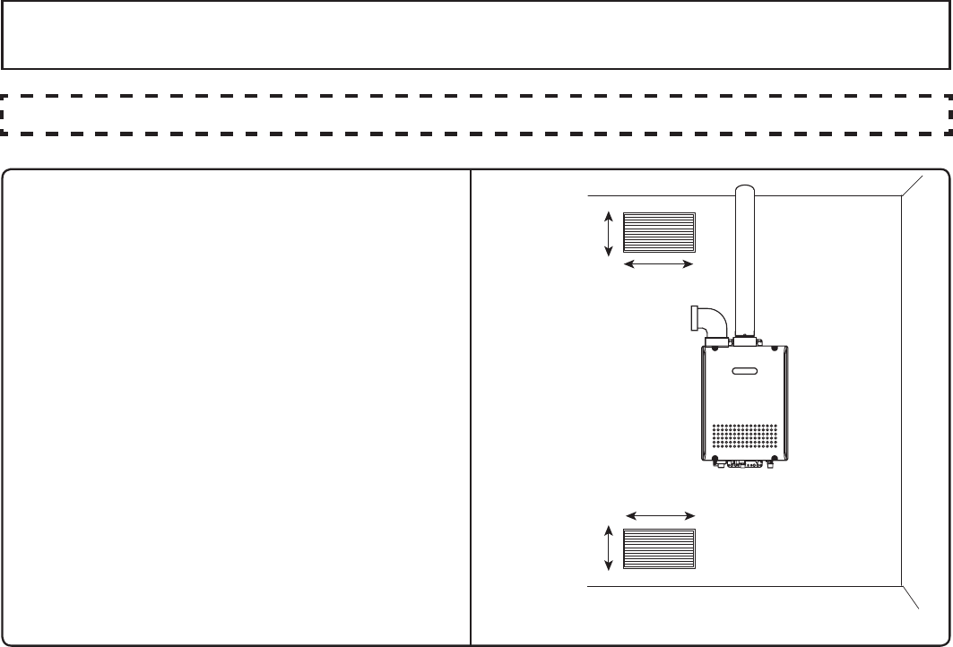
19
r)BCJMJUFEPTDBOBMFTQFSNBOFOUFTQBSB
permitir la circulación del aire de combustión.
r)BHBDBEBDBOBMEFQVMHBEBTDVBESBEBT
si suministran aire de interiores, y de 100
pulgadas cuadradas para aire exterior.
r4JMBVOJEBEFTUÃJOTUBMBEBFOVOBSNBSJP
mecánico, deje una separación de 24"
NNEFTEFFMGSFOUFEFMBVOJEBEIBTUBMB
puerta.
r4JTFWBBTVNJOJTUSBSFMBJSFEFDPNCVTUJÓO
a través de un conducto, ajústelo para
QSPQPSDJPOBSQJFTDÙCJDPTEFBJSFGSFTDP
por minuto.
Canales que suministran aire interior
10" (250mm)
20" (500mm)
10" (250mm)
20" (500mm)
Suministre aire de combustión a las unidades según el Código Nacional de Gas
Combustible, ANSI cZ223.1.
Aire de combustión
Proporcione aire adecuado para combustión como para no crear una presión negativa dentro del edificio.

20
Siga las instrucciones de su proveedor de gas.
9. Tuberías de gas
Tipo de gas
El tipo de gas indicado en la placa de características del calefactor de agua (NG o LP) debe coincidir
con el tipo de gas suministrado al calentador de agua.
Conversiones de gas
Si el tipo de gas suministrado no coincide con el tipo de gas en la placa de características, solicite el
reemplazo de la unidad con el tipo correcto de gas. Si debe realizarse una conversión del tipo de gas,
existen kits de conversión disponibles para algunos modelos. [El kit de conversión debe ser instalado
por un instalador/técnico de mantenimiento de Electrolux en conformidad con las instrucciones del
fabricante y todos los códigos y requisitos aplicables de la autoridad que tenga jurisdicción. El instalador/
técnico de mantenimiento autorizado de Electrolux es el responsable de la correcta instalación de este kit.
La instalación incorrecta de este equipo invalidará la garantía.
Contador
El contador de gas debe adaptarse adecuadamente para el calentador de agua y otros aparatos de gas
para su correcto funcionamiento. Seleccione un contador de gas capaz de suministrar toda la demanda
de bthu de todos los aparatos de gas del edicio.
Las pautas y ejemplos que hemos proporcionado en esta sección del manual son sólo de referencia.
La calibración y la instalación del sistema de gas para este calentador de agua, al igual que con otros aparatos
de gas, es responsabilidad exclusiva del instalador. El instalador debe estar capacitado profesionalmente
para realizar dichas tareas y siempre debe cumplir con las regulaciones y normas locales y nacionales.
Los cálculos del dimensionamiento de la línea de gas deben realizarse para cada instalación. Póngase
en contacto con Electrolux Home Products, Inc. en 1-888-360-8557 si tiene alguna pregunta o duda.
PRECAUCIÓN
Reguladores
Asegúrese de que todos los reguladores de gas utilizados funcionan bien y ofrecen presiones de
gas dentro de los intervalos especicados por el calentador de agua instalado.
El exceso de presión de entrada de gas puede provocar accidentes graves.
Presión
Compruebe la presión del suministro gas inmediatamente en secuencia ascendente en una ubicación
suministrada por la compañía de gas. La presión de gas suministrada debe estar dentro de los límites
indicados en el apartado de especicaciones con todos los aparatos de gas en funcionamiento. La presión
de gas de entrada debe estar dentro del intervalo especicado. Esto es para nes de ajuste de entrada.
La presión baja de gas puede provocar una pérdida de llama o fallos de encendido en otros aparatos de la
casa, lo que puede producir gas no quemado en el hogar. Podrían producirse serios accidentes, como por
ejemplo un incendio o explosión.
Medición de la presión de gas
Para comprobar la presión del suministro de gas en la unidad, se proporciona
un grifo en la entrada de gas. Retire el tornillo 9/32” de cabeza hexagonal/
tornillo Philips del grifo y conecte un manómetro mediante un tubo de silicona.
Abra al menos 2 elementos y mantenga pulsado el botón de presión máxima del
colector de botón en la placa de circuito. Llame a Electrolux Home Products,
Inc. para más información.
NOTA* Al comprobar la presión de suministro, asegúrese de que todos los demás aparatos de
gas se encuentran encendidos y en funcionamiento.
ADVERTENCIA:
PRECAUCIÓN
21
Prueba de presión
Debe comprobarse la existencia de fugas en el aparato y en sus conexiones antes de colocar el aparato en
funcionamiento. El aparato debe estar aislado del sistema de tubos de suministro de gas mediante la válvula
de cierre manual individual durante cualquier prueba de presión del suministro de gas en el sistema de tubos
a presiones de prueba iguales o inferiores a 1/2 psi (3,5 kPa). No recomendamos pruebas de presión que
sobrepasen los 1/2 psi (3,5 kPa). Si es necesario hacerlo, el aparato y su válvula de cierre individual deben estar
completamente desconectados del sistema de tubos de suministro de gas durante el proceso de la prueba.
Dimensionamiento de tubo/Conectores flexibles
Una válvula de cierre de gas debe ser instalada en la línea de suministro. Las líneas de gas exibles
no se recomiendan a menos que el diámetro interior mínimo sea de
3/4
” o superior y la capacidad
nominal del conector sea igual o superior a la capacidad BTU del calentador de agua. La tubería
de
gas debe estar en conformidad con los requisitos de la empresa de servicios local y/o en ausencia
de
estos códigos, utilice la última edición del código de gas combustible (NFPA54GC), ANSI Z223.1.
Cree la línea de gas de acuerdo con la demanda total del edicio y de longitud desde el contador o regulador
de tal modo que las siguientes presiones de suministro estén disponible incluso bajo demanda máxima.
Presión de suministro de gas natural
Mín. 4” WC
Máx. 10.5” WC
Presión de suministro de gas LP
Mín. 8” WC
Máx. 14” WC
Herramientas de referencia y cálculos de muestra
Las tablas y las muestras siguientes son solo de referencia. El profesional que dimensione e
instale la línea de gas debe siempre realizar los cálculos adecuados antes de toda instalación.
Qué tabla utilizar
r1BSBJOTUBMBDJPOFT/(DPOMBQSFTJÓOEFTVNJOJTUSPJOJDJBMFOFMQVOUPEFFOUSFHBFOFMDPOUBEPSQPS
ejemplo) es menor de 8” WC, use la tabla de caída de presión 0.5” WC (Tabla 1).
r1BSBJOTUBMBDJPOFTEF(/DPOMBQSFTJÓOEFTVNJOJTUSPJOJDJBMFOFMQVOUPEFFOUSFHBNBZPSPJHVBM
a 8” WC, use la tabla de caída de presión 3.0” WC (Tabla 2).
r1BSBUPEBTMBTJOTUBMBDJPOFTEF-1VUJMJDF5BCMB
TLa presión de entrada debe ser de al menos 5” WC para GN u 8” WC para todos los aparatos del
sistema de gas. Si la entrada de presión de gas cae por debajo de los 5” WC para GN u 8” WC para
LP, el calentador podría continuar funcionando, pero los demás aparatos del hogar podrían experimentar
una pérdida de llama o fallos en la ignición, lo que puede resultar en
en fugas de gas en el hogar. Consulte NFPA 54 para más detalles.
Póngase en contacto con Electrolux Home Products, Inc. para más información. Para tablas de capacidad
de tubos de acero inoxidable corrugado (CSST), póngase en contacto con el fabricante.
ADVERTENCIA:
PRECAUCIÓN
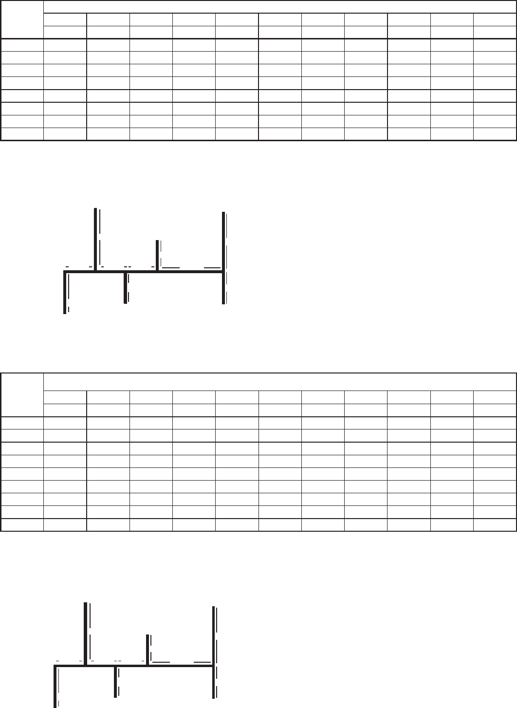
22
Tamaño
de
la tubería
Longitud (incluyendo accesorios)
10' 20' 30' 40' 50' 60' 70' 80' 90' 100' 125'
(3m) (6m) (9m) (12m) (15m) (18m) (21m) (24m) (27m) (30m) (38m)
3/4" 360 247 199 170 151 137 126 117 110 104 92
1" 678 466 374 320 284 257 237 220 207 195 173
1 1/4" 1,390 957 768 657 583 528 486 452 424 400 355
1 1/2" 2,090 1,430 1,150 985 873 791 728 677 635 600 532
2" 4,020 2,760 2,220 1,900 1,680 1,520 1,400 1,300 1,220 1,160 1,020
2 1/2" 6,400 4,400 4,400 3,020 2,680 2,430 2,230 2,080 1,950 1,840 1,630
3" 11,300 7,780 7,780 5,350 4,740 4,290 3,950 3,760 3,450 3,260 2,890
4" 23,100 15,900 12,700 10,900 9,660 8,760 8,050 7,490 7,030 6,640 5,890
Tabla 1. Para menos de 8” WC de presión de suministro inicial
Capacidad máxima de entrega de gas natural (caída de presión de 0.5”) [Schedule 40 Metalic Pipe]
Los valores de la tabla están en pies cúbicos de gas por hora (gravedad especíca 0,60, caída de presión 0.5”, presión de entrada de
menos de 2psi). Póngase en contacto con su proveedor para clasicaciones BTU/Pies cúbicos. Para simplicar sus cálculos, 1 pie
cúbico de gas es equivalente a aproximadamente 1,000 BTU.
Contador de
gas natural
CALENTADOR A GAS TIPO CONDENSADO
Electrolux (199,900 Btuh)
Secadora de ropas
(35,000 Btuh)
Barbacoa
(50,000 Btuh)
Cocina de gas
(65,000 Btuh)
10' (3m)
10' (3m)
10' (3m)
10' (3m)
5' (1.5m)
5' (1.5m)
5' (1.5m)
5' (1.5m)
Chimenea de gas
(25,000 Btuh)
Instrucciones
Ejemplo de línea de gas
Ejemplo de cálculo (UsarLa tabla de trago de presión de 0.5" WC)
Salida A: 45' (13.5m) (Use 50' (15m)), 50,000 Btuh requires 1/2"
Salida B: 40' (12m), 65,000 Btuh requires 1/2"
Sección 1: 45' (13.5m) (Use 50' (15m)), 115,000 Btuh requires 3/4"
Salida C: 30' (9m), 35,000 Btuh requires 1/2"
Sección 2: 45' (13.5m) (Use 50' (15m)), 150,000 Btuh requires 3/4"
Salida D: 25' (7.5m) (Use 30' (9m)), 25,000 Btuh requires 1/2"
Sección 3: 45' (13.5m) (Use 50' (15m)), 175,000 Btuh requires 1"
Salida E: 25' (7.5m) (Use 30' (9m)), 199,900 Btuh requires 1"
Sección 4: 45' (13.5m) (Use 50' (15m)), 374,900 Btuh requires 1-1/4"
sección 3 sección 2 sección 1
Salida A
Salida B
Salida C
Salida D
Salida E
5' (1.5m)5' (1.5m)
sección 4
1.
Ajuste cada ramal de salida comenzando por el más alejado
usando el Btuh requerido y la longitud desde el contador.
2.
Ajuste cada sección de la línea principal usando la longitud
hasta la salida más alejada y el Btuh requerido en esa sección.
Tabla 2. Para 8” WC – 10.5” WC de presión de suministro inicial
Capacidad máxima de entrega de gas natural (caída de presión de 3.0”) [Schedule 40 Metalic Pipe]
Los valores de la tabla están en pies cúbicos de gas por hora (gravedad especíca 0.60, caída de presión 3.0”, 8.0” WC o presión
de suministro mayor, presión de entrada de menos de 2psi). Póngase en contacto con su proveedor para clasicaciones BTU/Pies
cúbicos. Para simplicar sus cálculos, 1 pie cúbico de gas es equivalente a aproximadamente 1,000 BTU.
Contador de
gas natural
CALENTADOR A GAS TIPO CONDENSADO
Electrolux (199,900 Btuh)
Secadora de ropas
(35,000 Btuh)
Barbacoa
(50,000 Btuh)
Cocina de gas
(65,000 Btuh)
10' (3m)
10' (3m)
10' (3m)
10' (3m)
5' (1.5m)
5' (1.5m)
5' (1.5m)
5' (1.5m)
Chimenea de gas
(25,000 Btuh)
Instrucciones
Ejemplo de línea de gas
Ejemplo de cálculo (UsarLa tabla de trago de presión de 3.0" WC)
Salida A: 45' (13.5m) (Use 50' (15m)), 50,000 Btuh requires 1/2"
Salida B: 40' (12m), 65,000 Btuh requires 1/2"
Sección 1: 45' (13.5m) (Use 50' (15m)), 115,000 Btuh requires 1/2"
Salida C: 30' (9m), 35,000 Btuh requires 1/2"
Sección 2: 45' (13.5m) (Use 50' (15m)), 150,000 Btuh requires 1/2"
Salida D: 25' (7.5m) (Use 30' (9m)), 25,000 Btuh requires 1/2"
Sección 3: 45' (13.5m) (Use 50' (15m)), 175,000 Btuh requires 1/2"
Salida E: 25' (7.5m) (Use 30' (9m)), 199,900 Btuh requires 1/2"
Sección 4: 45' (13.5m) (Use 50' (15m)), 374,900 Btuh requires 3/4"
sección 3 sección 2 sección 1
Salida A
Salida B
Salida C
Salida D
Salida E
5' (1.5m)5' (1.5m)
sección 4
1.
Ajuste cada ramal de salida comenzando por el más alejado
usando el Btuh requerido y la longitud desde el contador.
2.
Ajuste cada sección de la línea principal usando la longitud
hasta la salida más alejada y el Btuh requerido en esa sección.
Tamaño
de
la tubería
Longitud (incluyendo accesorios)
10' 20' 30' 40' 50' 60' 70' 80' 90' 100' 125'
(3m) (6m) (9m) (12m) (15m) (18m) (21m) (24m) (27m) (30m) (38m)
1/2" 454 312 250 214 190 172 158 147 138 131 116
3/4" 949 652 524 448 397 360 331 308 289 273 242
1" 1,787 1,228 986 844 748 678 624 580 544 514 456
1 1/4" 3,669 2,522 2,025 1,733 1,536 1,392 1,280 1,191 1,118 1,056 936
1 1/2" 5,497 3,778 3,034 2,597 2,302 2,085 1,919 1,785 1,675 1,582 1,402
2" 10,588 7,277 5,844 5,001 4,433 4,016 3,695 3,437 3,225 3,046 2,700
2 1/2" 16,875 11,598 9,314 7,971 7,065 6,401 5,889 5,479 1,540 4,856 4,303
3" 29,832 20,503 16,465 14,092 12,489 11,316 10,411 9,865 9,087 8,584 7,608
4" 43678 30,020 24,107 20,632 18,286 16,569 15,243 14,181 13,305 12,568 11,139

23
Tabla 3. Propano sin diluir máximo (PL) capacidad de entrega en miles de
BtuH (caída de presión 0.5” WC) [Schedule 40 Metalic Pipe]
Sólo para referencia. Consulte con el fabricante del tubo de gas para las capacidades reales del tubo.
Comprobación final
Una vez completada la instalación, verique que la entrada de presión de gas de todo el sistema
de gas no baje de 5” WC para GN u 8” WC para LP en todos los aparatos. Esto se puede
comprobar encendiendo todos los aparatos de gas de combustión, incluyendo el calentador
de agua y, a continuación, compruebe la presión de entrada en cada aparato para vericar que
todos los aparatos estén recibiendo un mínimo de 5” WC para GN u 8” WC para LP. Si todos
los aparatos no están recibiendo la presión de entrada mínima podría ser necesario cambiar el
sistema de la tubería de gas.
Tamaño
de
la tubería
Longitud (incluyendo accesorios)
10' 20' 30' 40' 50' 60' 70' 80' 90' 100' 125' 150' 200'
(3m) (6m) (9m) (12m) (15m) (18m) (21m) (24m) (27m) (30m) (38m) (45m) (60m)
1/2" 275 189 152 129 114 103 96 89 83 78 69 63 55
3/4" 567 393 315 267 237 217 196 185 173 162 146 132 112
1" 1,071 732 590 504 448 409 378 346 322 307 275 252 213
1 1/4" 2,205 1,496 1,212 1039 913 834 771 724 677 630 567 511 440
1 1/2" 3,307 2,299 1,858 1,559 1,417 1,275 1,181 1,086 1,023 976 866 787 675
2" 6,221 4,331 3,465 2,992 2,646 2,394 2,205 2,047 1,921 1,811 1,606 1,496 1,260
ADVERTENCIA:
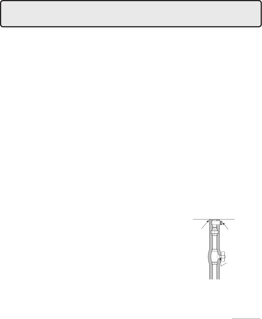
24
10. Tuberías de agua
Este aparato está diseñado para la combinación de agua potable y calefacción. No se puede usar solamente
como calefacción. No utilice este aparato si alguna de sus partes ha estado bajo el agua. Llame inmediatamente
a un técnico calicado para inspeccionar el aparato y cambie cualquier pieza del sistema de control y ajuste de
gas que haya estado bajo el agua.
Si el calentador de agua se encuentra instalado en un sistema cerrado de suministro de agua, como por ejemplo
uno que tenga un desconector en la línea de suministro de agua fría, se deben proporcionar los medios para
controlar la expansión térmica. Póngase en contacto con el proveedor de agua o un inspector local de fontanería
para conocer cómo controlar esta situación.
Se puede instalar una válvula de alivio de presión cerca de la salida de agua caliente que tenga capacidad y
cumpla con las normas para válvulas de alivio y dispositivos de cierre automático para los sistemas de suministro
de agua caliente, ANSI Z21.22, o el Código de Calderas y Recipientes a Presión ANSI/ASME, sección IV (calderas
de calefacción). La válvula de alivio de presión debe ser capaz de sostener temperaturas de descarga de vapor de
199,900 Btuh. Se pueden usar varias válvulas. La capacidad de alivio de presión no debe exceder los 150 psgi.
No se debe colocar ninguna válvula entre la valvula de alivio y el calentador de agua. La válvula de alivio se debe
instalar de forma tal que la descarga sea enviada a un lugar adecuado para su eliminación cuando se produzca
el alivio. No se debe instalar un acoplamiento de reducción u otra restricción en la línea de descarga. La línea de
descarga se debe instalar de forma tal que permita un desagüe completo de la válvula y la tubería. Si esta unidad
se instala con un depósito independiente, deberá tener su propia válvula de alivio de temperatura y presión. Esta
válvula también debe cumplir con las normas para válvulas de alivio y dispositivos de cierre automático para los
sistemas de suministro de agua caliente, ANSI Z21.22 (en Estados Unidos solamente). La válvula de alivio de
temperatura no es obligatoria, pero si se usa alguna, no la instale con la sonda directamente en el ujo de agua.
Esto puede provocar una descarga innecesaria de la válvula.
Las tuberías y sus componentes conectados al calentador de agua deben ser apropiados para su uso con agua potable.
Productos químicos como los utilizados en el tratamiento del agua de calderas no se introducirán en el agua potable.
Un calentador de agua usado para suministrar agua potable probablemente no se pueda conectar a ningún sistema
o componentes de calefacción usados anteriormente con algún calentador de agua no potable.
Cuando alguna parte del sistema necesita el agua a una temperatura superior que en el resto del sistema, se
deben instalar medios como la válvula mezcladora para suavizar el agua y reducir el peligro de quemaduras.
La instalación y las reparaciones deben ser realizadas por un plomero
calicado. En la Mancomunidad de Massachusetts, este producto lo debe
instalar un plomero o instalador de gas certicado según el código de plomería
y gas combustible de Massachusetts 248 CMR Secciones 2.00 y 5.00. Respete
todos los códigos aplicables
r %FTDBSHVF FM BHVB B USBWÊT EF MB UVCFSÎB QBSB MJNQJBS FM QPMWP EF NFUBM MB BSFOB Z MB TVDJFEBE BOUFT EF
conectarla.
r &KFDVUFMBTTJHVJFOUFTNFEJEBTEFBJTMBNJFOUPQBSBQSFWFOJSMBDPOHFMBDJÓO
- Tome las medidas adecuadas de aislamiento de calor (por
ejemplo, envolver con materiales de aislamiento térmico, uso de
calentadores eléctricos) según el clima de la región para evitar que
se congelen las tuberías.
- Cerciórese de que no haya fugas de agua de las tuberías de suministro
de agua fría y caliente, y aísle completamente las tuberías.
- También asegúrese de aislar completamente la válvula de suministro
de agua y las conexiones de agua fría y caliente en el calentador de
agua (Consulte la gura a la derecha).
- No cubra el conector del desagüe con material aislante para que
pueda drenarse el agua de la tubería. (Consulte la gura a la derecha.)
r
Use una unión de acoplamiento o tubería exible para hacer la conexión y reducir la fuerza aplicada a las
tuberías.
r /PVTFUVCFSÎBTDPOVOEJÃNFUSPNFOPSRVFFMBDPQMBNJFOUP
r $VBOEPMBQSFTJÓOEFMBHVBEFBMJNFOUBDJÓOFTNVZBMUBJOUSPEV[DBVOBWÃMWVMBEFQVSHBPUPNFmedidas de
prevención del golpe de ariete.
r &WJUFFMVTPEFKVOUBTFOMBNFEJEBEFMPQPTJCMFQBSBNBOUFOFSFMTJTUFNBEFUVCFSÎBTTJNQMF
r &WJUFRVFFOFMTJTUFNBEFUVCFSÎBTTFQSPEV[DBVOBSFUFODJÓOEFBJSF
r 4JTFJOTBMBMBVOJEBEFOFMUFDIP
- Si la unidad se instala en el techo para suministrar agua a niveles inferiores, asegúrese de que la presión de
agua suministrada a la unidad no sea menor que 29 psi. Podría ser necesario instalar un sistema de bombeo
para asegurar que la presión de agua se mantenga a este nivel.
- Compruebe la presión antes de poner la unidad en funcionamiento.
- No suministrar la presión adecuada a la unidad, puede provocar que el funcionamiento sea ruidoso, que el
tiempo de vida útil sea más corto y que la unidad se apague con frecuencia.
Aísle completamente la
entrada de agua los
accesorios de salida.
No cubra el conector
del desagüe con
material aislante para
que pueda drenarse el
agua de la tubería.
Aísle completamente la
válvula de suministro
de agua.
25
Tuberías de suministro de agua
r
No use PVC, hierro o tubería que haya sido tratada con
cromatos, sello de caldera u otras sustancias químicas.
r
Monte una válvula de retención y una de cierre (cerca de
la entrada).
r1BSBRVF FMDMJFOUFVTF FMDBMFOUBEPS EFBHVB
cómodamente se necesita de 98.1 a 491 kPa
(14 a 70 PSI) de presión del suministro de
agua.
Asegúrese de comprobar la presión del agua.
Si la presión del agua es baja, el calentador
de a gu a no p ue de f un cion ar a t od a su
capacidad, y puede convertirse en una fuente
de problemas para el cliente.
Tuberías de desagüe
r&MBHVBEFFYQBOTJÓOQVFEFDBFSEFMBWÃMWVMB
de alivio de presión y mojar el piso.
Si es necesario, coloque tuberías de desagüe
o use una manguera de desagüe para quitar el
agua.
Tuberías de agua caliente
r/P VTF 17$ IJFSSP P UVCFSÎB RVF IBZB TJEP
tratada con cromatos, sello de caldera u otras
sustancias químicas.
r$VBOUP NÃT MBSHB TFBO MBT UVCFSÎBT NBZPS
perdida de calor. Trate de hacer el sistema de
tuberías lo más corto posible.
r6TFWÃMWVMBTNF[DMBEPSBTDPOQPDBSFTJTUFODJB
al agua. Use cabezas de ducha con pérdida de
presión baja.
r4JFTOFDFTBSJPVTFVOBCPNCBVPUSPNFEJP
para asegurar que la presión de suministro de
agua a la entrada del calentador no baje a menos
de 29 PSI en el momento de demánda máxima de
agua. También instale un contador de presión en
la entrada. Si esto no se hace, se producirá una
ebullición local dentro del calentador de agua
provovando sonidos anormales y reduciendo la
durabilidad del intercambiador de calor.
Prevención de congelación
r-B DPOHFMBDJÓO TF QSFWJFOF BVUPNÃUJDBNFOUF EFOUSP EFM BQBSBUP B NFOPT RVF MB UFNQFSBUVSB
exterior sin viento esté por debajo de -30°F (-35°C).
*
Cuando el aire de combustión se suministra desde interiores, la temperatura ambiente debe estar por
encima de
32°F
(0°C) para evitar el congelamiento y el espacio no debe tener presión negativa.
r4J FTUF NPEFMP TF JOTUBMB FO VO ÃSFB EPOEF MB UFNQFSBUVSB FYUFSJPS QVFEF BDFSDBSDF B MBT
condiciones de congelación de -30°F (-35°C) o menos, entonces se deben proporcionar medidas
de protección adicionales. Para conocer las medidas de protección contra congelación, consulte el
manual de uso y cuidado.
r-PT DBMFOUBEPSFT EF QSFWFODJÓO DPOUSB DPOHFMBDJÓO OP FWJUBO RVF MBT UVCFSÎBT FYUFSOBT EF MB
unidad se congelen.
Proteja estas tuberías con aislamiento, cinta térmica, solenoides o cubiertas de tuberías.
r1BSB RVF MPT DBMFOUBEPSFT EF QSFWFODJÓO DPOUSB DPOHFMBDJÓO GVODJPOFO FM DBMFOUBEPS EF BHVB
debe estar conectado a la alimentación a todo momento.

26
Tratamiento del agua
Sistema de tratamiento del agua
Suministro de
agua de la ciudad
Válvula al
ivio de
presión
Agua caliente para los dispositivos
Válvula de cierre
Desagüe
Frío para el
calentador
de agua
Filtro de sedimento
opcional
Dispositivo de tratamiento del agua
Válvula de cierre
Tipo de agua
Nivel de
dureza
Nivel de
dureza
Dispositivo de
tratamiento
Dispositivo de
tratamiento
Frecuencia
de vaciado*
Frecuencia
de vaciado*
Suave
Tipo de agua
Suave
0-1gpg
1-3gpg
(0-17mg/L)
Ninguno
Ninguno
Ninguno
Ninguno
Ninguno
Ninguno
Ninguno
Ninguno
Ligeramente
dura
Ligeramente
dura
(17-51mg/L)
Moderadamente
dura Moderadamente
dura
Dura Dura
3-7gpg
(51-120mg/L)
Una vez al año**
Una vez al año**
Una vez al año**
Dos veces al año**
7-10gpg
(120-171mg/L)
Muy dura Muy dura
10-14gpg
(171-239mg/L)
Tratamiento
requerido
Tratamiento
requerido
Tratamiento
requerido
Tratamiento
requerido
Extremadamente
dura Extremadamente
dura
> 14gpg
(> 239mg/L)
0-1gpg
1-3gpg
(0-17mg/L)
(17-51mg/L)
3-7gpg
(51-120mg/L)
7-10gpg
(120-171mg/L)
10-14gpg
(171-239mg/L)
> 14gpg
(> 239mg/L)
* Instale válvulas de aislamiento para permitir el vaciado.
** El vaciado es obligatorio si no se instala un dispositivo para el
tratamiento del agua.
* Instale válvulas de aislamiento para permitir el vaciado.
** El vaciado es obligatorio si no se instala un dispositivo para el
tratamiento del agua.
Normas de tratamiento para uso residencial Normas de tratamiento para uso comercial
Inhibidor de
descalcicación
Inhibidor de
descalcicación
Inhibidor de
descalcicación
Inhibidor de
descalcicación
Inhibidor de
descalcicación
Inhibidor de
descalcicación
Inhibidor de
descalcicación
Inhibidor de
descalcicación
CALENTADOR A
GAS TIPO
CONDENSADO
Electrolux
Si este calentador de agua se va a instalar en una conexión donde el agua que se suministra es dura,
se debe tratar el agua con suavizador de agua o inhibidor de incrustaciones. Consulte las siguientes
tablas para las medidas de tratamiento y mantenimiento que se deben tomar según el nivel de dureza
del agua. Los daños en el calentador de agua provocados agua con una dureza por encima de 12 gpg
(200 mg/L) no están cubiertos en la garantía de Electrolux Home Products, Inc.
/PUB -PT TVBWJ[BEPSFT EF BHVB QVFEFO FTUBS SFHVMBEPT QPS MB KVSJTEJDDJÓO MPDBM EF BHVB DPOTVMUF
con el fabricante los códigos, mediciones y normas de instalación
; el siguiente diagrama es solo
como referencia.
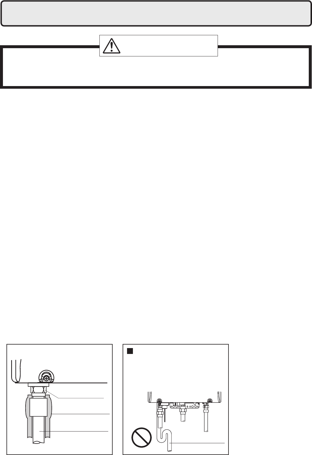
27
r&TUF DBMFOUBEPS EF BHVB FT VO BQBSBUP EF EF BMUB FGJDBDJB DPO DPOEFOTBDJÓO UPUBM RVF QSPEVDF
condensado acídico durante el funcionamiento. El calentador de agua incorpora un sistema de recogida
y eliminación que debe drenarse adecuadamente para asegurar su funcionamiento correcto.
r&MOJWFMEFQ)EFMDPOEFOTBEPFTEFBQSPYJNBEBNFOUF4FEFCFJOTUBMBSVOOFVUSBMJ[BEPSFYUFSOPFO
las tuberías de desagüe cuando el código local lo exija o cuando el condensado pueda provocar daños.
r4J TF JOTUBMB VO OFVUSBMJ[BEPS FYUFSOP TFSÃ OFDFTBSJP DBNCJBS QFSJÓEJDBNFOUF FM BHFOUF
neutralizante. Consulte las instrucciones proporcionadas con el neutralizador para conocer los
intervalos de cambio.
r1BSB ESFOBS FM DPOEFOTBEP TF QSPQPSDJPOB VOB DPOFYJÓO DPO SPTDB EF FO MB CBTF EFM
calentador de agua.
No reduzca el tamaño de este accesorio o de las tuberías de desagüe a menos de 1/2".
En climas fríos, no drene el condensado hacia el exterior. Si la tubería de desagüe se congela con el
agua fría, la tubería no drenará el condensado y la unidad dejará de funcionar.
r6TFUVCFSÎBT QMÃTUJDBTDPNP MB17$QBSB MBMÎOFB EFEFTBHÛF/P VTFBDFSPIJFSSPOFHSPV PUSP
material que pueda corroerse cuando se ponga en contacto con el condensado acídico
r.BOUFOHBMBMPOHJUVEEFMBUVCFSÎBEFEFTBHÛFMPNÃTDPSUBQPTJCMF&OUSBNPTMBSHPTPDPOFYJPOFT
donde el desagüe más cercano esté por encima del calentador de agua será necesario usar una
bomba de condensado. Ajuste la bomba para permitir una descarga de condensado máximo de 2
GPM desde el calentador de agua.
r-PT USBNPT IPSJ[POUBMFT TF EFCFO JODMJOBS QPS QJF FO EJSFDDJÓO B MB CPNCB EF EFTBHÛF P
condensado. El condensado se descargará solamente por gravedad. Haga el tramo de la tubería de
desagüe lo más corto posible.
r&M FYUSFNP EF MB UVCFSÎB EF EFTBHÛF OP EFCF FTUBS TVNFSHJEP FO BHVB P CMPRVFBEP EF OJOHVOB
forma. Para asegurar un drenaje correcto, deje el extremo de la tubería de desagüe abierto al
exterior. No tiene un sifón. También asegúrese de que no haya obstrucciones bloqueando la
descarga de condensado en la línea de desagüe.
r"TFHÙSFTFEFDPNQSPCBSRVFFMDPOEFOTBEPáVZFMJCSFNFOUFQPSMBUVCFSÎBEFEFTBHÛFDVBOEPFM
sistema se haya instalado. El condensado comenzará a salir del calentador de agua a los 15 minutos
de funcionamiento.
r5PNF NFEJEBT QBSB FWJUBS RVF MBT MÎOFBT EF EFTBHÛF TF DPOHFMFO BJTMBNJFOUP DJOUB UÊSNJDB
calentadores eléctricos, etc.).
11. Tuberías de condensado
Tubería de desagüe
Tubería de desagüe
Conexión del
desagüe
Material de aislamiento
del calor
Calentador de agua
No monte la línea de desagüe
cuando la sección horizontal
se haya introducido. Siempre
monte la línea de desagüe
hacia abajo para asegurar el
desagüe apropiado.
Debido al carácter ácido del condensado, asegúerese de drenar adecuadamente y si es
necesario, tratar el condensado antes de su eliminación. Los daños causados por el uso
incorrecto del condensado no están cubiertos en la garantía.
PRECAUCIÓN
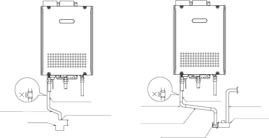
28
Incline la tubería hacia
abajo 1/4" por pie. El extremo de la tubería
de desagüe debe tener
un espacio vacío.
El extremo de la tubería
de desagüe debe tener
un espacio vacío.
Tuberías de condensado para el desagüe de piso.
Incline la tubería hacia
abajo 1/4" por pie.
Codo de 1/2" PVC
Codo de 1/2" PVC Tubos ID de 3/8"
* Instale las tuberías de acuerdo con la
bomba Instrucciones del fabricante.
Tuberías de condensado con bomba
Bomba de condensado
Desagüe de piso
MANTENER SEPARACIÓN
Tubería de 1/2" PVC
NO AGREGUE
NINGUNA
VÁLVULA
CALENTADOR A
GAS TIPO
CONDENSADO
Electrolux
CALENTADOR A
GAS TIPO
CONDENSADO
Electrolux
NO AGREGUE
NINGUNA
VÁLVULA
/PUB
Si la línea de drenaje se obstruye o se congela, el condensado regresará al calentador de agua y
aparecerá parpadeando el código de error "29" en el control remoto y se detendrá el funcionamiento.
Si esto sucede, quite la obstrucción o congelación para que el condensado pueda uir libremente.
Asegúrese de inclinar la tubería de desagüe, use la tubería con la longitud correcta, deje la separación
adecuada, y aplique medidas de prevención contra congelación (si es necesario) para evitar que la
tubería de desagüe se obstruya o congele.
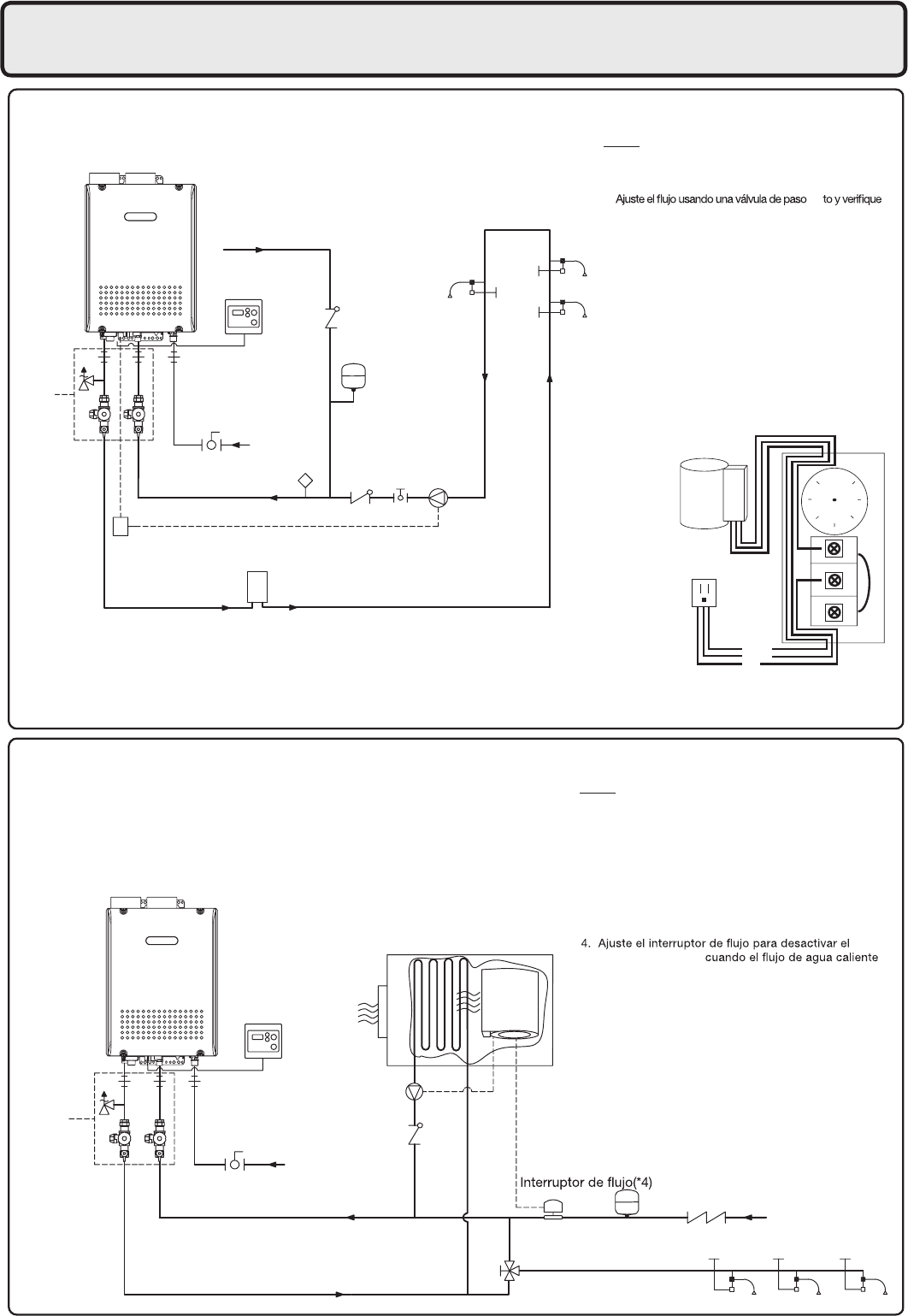
29
Sistema de recirculación
Sistema de combinación de agua potable y calefacción
R
B
W
Pump
120VAC
105
neutral
tierra
vivo
S
Suministro de gas
Desconector
(opcional)
Comprobar
válvula(*3)
Suministro de
agua fría
Depósito de expansión
opcional(*6)
Válvula mezcladora(*5)
Agua caliente
Bomba(*2)
Dispositivos
Controlador de aire
Notas:
Notas:
Cableado de Aquastat
Use el Aquastat Honeywell
(Modelo L6006A o L6006C)
1. Ajuste la bomba para proporcionar un máximo de 2
GPM (7.5 L/min.) a través del sistema a 10 pies (3m)
a las pérdidas de presión.
rec
el caudal con los monitores de mantenimiento.
2. El método preferido para controlar la recirculación
de la bomba es la señal de control de la bomba.
Se debe usar una conexión de relé en bombas
superiores a 85W Si no se usa la señal de control de la
bomba, se puede usar un Aquastat para controlar la bomba.
3. Use el Aquastat si el calentador de agua no controla
la bomba.
Ajuste el Aquastat a 10°F (5°C) por debajo de la
temperatura de salida.
4. Electrolux recomienda el uso de un Kit de
Aislamiento con la instalación.
Estos kits incluyen una válvula de cierre y reparación
integrada con las uniones y una válvula alivio de presión.
1. Electrolux recomienda el uso de un Kit de Aislamiento
con la instalación.
Estos kits incluyen una válvula de cierre y reparación
integrada con las uniones y una válvula alivio de presión.
2. Ajuste la bomba para proporcionar un máximo de 3
GPM (11.3 L/min.) con una presión igual a la pérdida en
el calentador de agua y el controlador de aire.
3. Es necesario comprobar la válvula si no viene incluida
con la bomba.
controlador de aire
alcanza los 3 GPM (11.3 L/min.).
Ajústelo según sea necesario para evitar ciclos.
5. Si el sistema necesita agua para la calefacción a
temperaturas más altas que para otros usos, se pueden
proporcionar medios como la válvula mezcladora para
suavizar el agua para los otros usos y ayudar a evitar
quemaduras.
6. Se necesitan depósitos de expansión si se instala un
desconector.
7. El calentador de agua no se puede usar solamente
como calefacción.
8. Solo podrá conectarse agua POTABLE a través del
calentador de agua.
Suministro de agua fría
Kit de
Aislamiento(*4)
Suministro
de gas
Aquastat(*3)
Señal de control de la bomba(*2)
Relé para la bomba
(Si es superior a 85 Watts)
Agua caliente
Depósito de almacenamiento de
8-10 Galones opcional
(Para atenuar el intercalado de agua fría)
Válvula de
paso recto
Bomba(*1)
Depósito de
expansión
(Instalar según
el código local)
Dispositivos
Retorno de agua
caliente
CALENTADOR A
GAS TIPO
CONDENSADO
Electrolux
Kit de
Aislamiento(*1)
CALENTADOR A
GAS TIPO
CONDENSADO
Electrolux
12. Conexiones de las tuberías
30
No conecte la la fuente de alimentación a la unidad hasta que se haya completado
todo el cableado eléctrico.
Consulte a un electricista calicado
para el trabajo eléctrico.
13. Cableado eléctrico
Este aparato debe estar conectado a tierra según los códigos locales, o en su ausencia, con el Código
Eléctrico Nacional, ANSI/NFPA 70
1SFDBVDJÓO.BSRVFUPEPTMPTDBCMFTBOUFTEFEFTDPOFDUBSMPTDVBOEPTFMFIBHBNBOUFOJNJFOUP
Los errores en el cableado pueden provocar funcionamientos incorrectos y peligrosos.
Después del mantenimiento, verique que el funcionamiento sea correcto.
Cableado de campo que se debe realizar en el momento de la instalación del aparato.
r&MTVNJOJTUSPFMÊDUSJDPRVFOFDFTJUBFMDBMFOUBEPSEFBHVB
es de 120VAC a 60 Hz.
El consumo eléctrico puede ser de hasta 306W o mayor
si se usan accesorios opcionales.
Use un circuito adecuado.
r
No desconecte la alimentación cuando no se esté usando.
Cuando está apagado no se activa la prevención contra
congelación lo que puede provocar posibles daños de
congelación.
r/PQFSNJUBRVFFMDBCMFFMÊDUSJDPIBHB
contacto con las tuberías de gas.
Amarre el cable sobrante
por
fuera del calentador de agua. Si
pone el cable sobrante dentro del
calentador de agua puede provicar
interferencias eléctricas y un
funcionamiento defectuoso.
Desconecte la alimentación
Peligro de descarga eléctrica
No encienda el aparato hasta que no haya terminado el cableado eléctrico. Desconecte la
alimentación antes del mantenimeinto.
Si no lo hace puede provocar la muerte o lesiones graves por descarga eléctrica.
ADVERTENCIA:
La descarga electrostática puede afectar componentes eléctricos. Tome precauciones para
prevenir descargas
electrostáticas de personas o herramientas durante la instalación y el
mantenimiento del calentador de agua para Proteger el control electrónico del producto.
PRECAUCIÓN
Tierra
r1BSB FWJUBS EFTDBSHBT FMÊDUSJDBT QSPQPSDJPOF VOB UJFSSB DPO VOB SFTJTUFODJB NFOPS RVF .
Este trabajo debe realizarlo un electricista.
No conecte la tierra al suministro de agua de la ciudad ni a las tuberías de gas. No amarre la tierra a
una línea telefónica.
Instalación del disyuntor
r$POFDUF VO EJTQPTJUJWP RVF EFTDPOFDUF BVUPNÃUJDBNFOUF MB DPSSJFOUF JOUFSSVQUPS EJGFSFODJBM
cuando se detecte una fuga eléctrica.

31
Control remoto
Instale el control remoto según las instrucciones de la Guía de Instalación (página 38).
* Solo se puede conectar un control remoto al calentador de agua.
La conexión de dos o más controles remotos pueden provocar averías.
* El calentador de agua tiene un ajuste de fábrica que permite un ajuste de temperatura máxima
de [120 °F / 50 °C].
Para acceder a temperaturas más altas a través del control remoto, siga los siguientes pasos.
<Para ajustar la temperatura máxima a [125 -140 °F / 55 - 60 °C]>
1. Apague el calentador de agua presionando el botón de Encendido/Apagado del control remoto.
2.
Mantenga presionado el botón AJUSTE ALARMA DEL FLUJO hasta que escuche un sonido (2 sec.) y vea
en la pantalla
[120 °F / 50 °C]
.
3.
Ajuste el límite superior de la temperatura del suministro de agua caliente a [125 °F, 130 °F, 135 °F o 140 °F
/ 55 °C o 60 °C]
usando los botones ARRIBA y ABAJO.
4. Para volver a encender el calentador de agua, presione el botón de Encendido/Apagado del control remoto.
Para mantener apagado el calentador de agua, deje reposar la unidad por 30 seg. para regresar a la
pantalla original.
r&TUBVOJEBETFQVFEFQSPHSBNBSQBSBRVFUFOHBVOBEFFTUBTUSFTUFNQFSBUVSBTQPSEFGFDUPTJTF
quita el control remoto [140 °F (60 °C), 135 °F (57 °C), 120 °F (50 °C)]. Para cambiar la temperatura
predeterminada, ajuste los interruptores dip como se describe a continuación. La temperatura por
defecto es 120 °F (50 °C).
1. Desconecte la alimentación del calentador de agua.
2. Quite la cubierta frontal del calentador de agua (4 tornillos).
3. Desconecte el control remoto. Ajuste los interruptores dip como se ilustra a continuación.
4. Vuelva a colocar la cubierta frontal del calentador de agua (4 tornillos).
5. Vuelva a conectar la alimentación del calentador de agua.
r$VBOEPDBNCJFMBUFNQFSBUVSBDFSDJÓSFTFEFDPOàSNBSDPOFMDMJFOUFRVFMBUFNQFSBUVSBEFM
agua caliente será muy alta y hay riesgo de quemaduras.
r-BTUFNFQSBUVSBTEFBHVBDBMJFOUFQPSFODJNBEF'$QVFEFOQSPWPDBSRVFNBEVSBT
graves instantáneamente o la muerte por quemaduras.
PELIGRO
* Comentarios [125 °F / 55 °C]
modo de visualización en Ferenheit
modo de visualización en Celsius
* No cambie ninguno de los interruptores.
* Temperatura alta.
1 2
ENCENDIDO=
APAGADO=
120 F (50 C)
135 F (57 C)
140 F (60 C)
APAGADO
ENCENDIDO
Comprobar
Comprobar
Comprobar
Comprobar
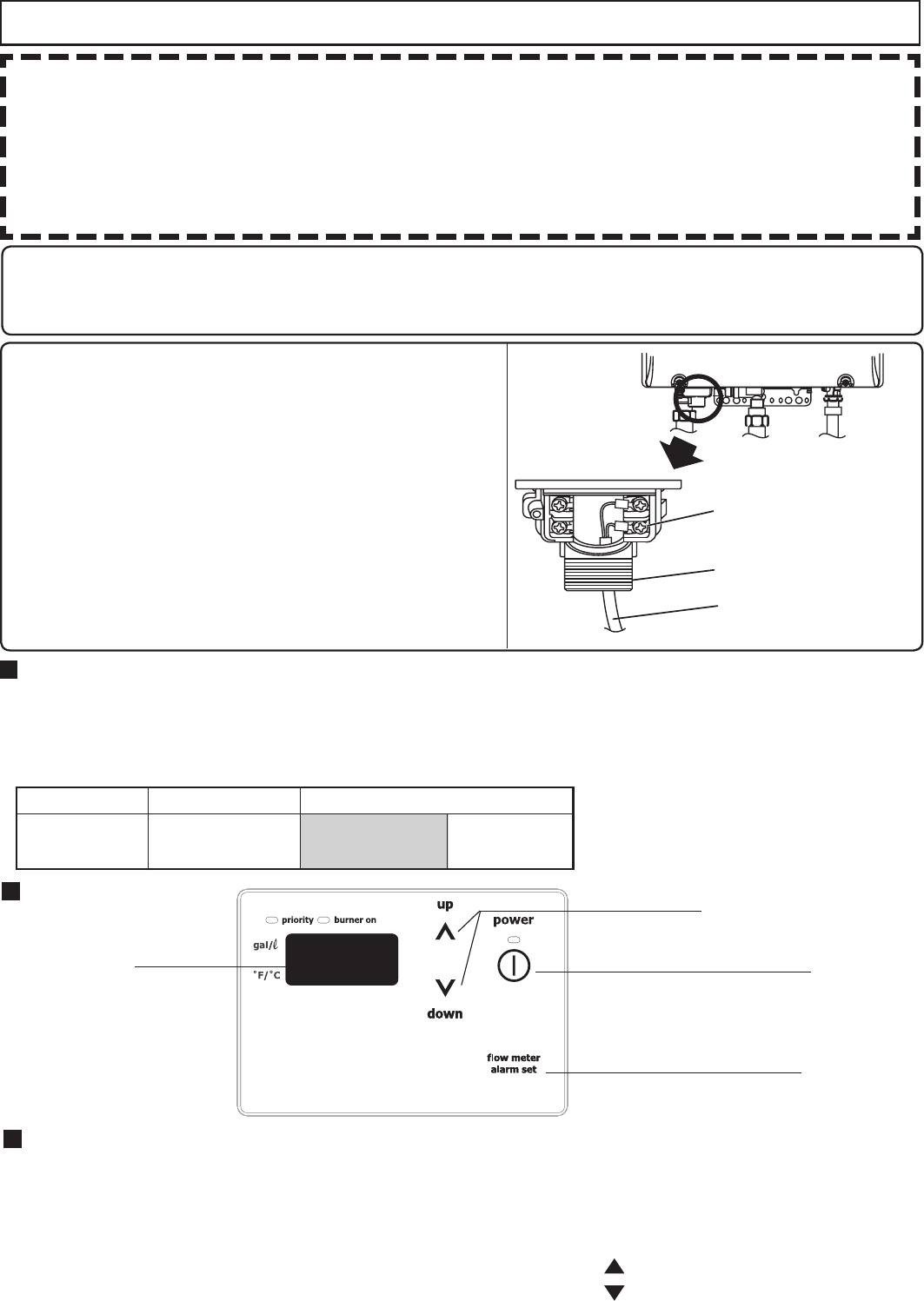
32
Cable del control remoto
r1BSBFYUFOTJPOFTVTFVODBCMF"8(
r)BHBMBJOTUBMBDJÓOTFHÙOFM$ÓEJHP&MÊDUSJDP/BDJPOBMZUPEPTMPTDÓEJHPTMPDBMFTBQMJDBCMFT
Conexión del cable del control remoto a la unidad
r .BOUFOHB FM DBCMF EFM DPOUSPM SFNPUP BMFKBEPT EF MPT DBMFOUBEPSFT EF QSFWFODJÓO DPOUSB
congelación de la unidad.
r
Amarre el cable sobrante por fuera del calentador de agua. No ponga el cable sobrante dentro del equipo.
r&MDBCMFEFMDPOUSPMSFNPUPTFQVFEFFYUFOEFSIBTUBhNDPOVODBCMF"8(
r6TFVOUFSNJOBMUJQP:DPOVOUVCPEFSFTJOB4JOFMUVCPFMDBCMFEFDPCSFTFQVFEFDPSSPFSZ
causar problemas).
r"TFHÙSFTFEFBQSFUBSDPOMBNBOPDVBOEPMPBUPSOJMMFBMCMPRVFEFUFSNJOBMFT-BTIFSSBNJFOUBT
eléctricas pueden provocar daños al bloque de terminales.
1. Compruebe que el cable del control remoto tiene
longitud suciente como para llegar al bloque de
terminales para la conexión externa.
2. Desconecte la alimentación del calentador de agua.
3. Quite el tornillo que asegura la cubierta del bloque
de terminales y retírela.
4.
Pase el cable del control remoto a través de la entrada
EFMDBCMFBEPZDPOFDUFMPTUFSNJOBMFT:EFMFYUSFNP
del cable del control remoto al bloque de terminales.
5. Vuelva a colocar la cubierta del bloque de terminales y
ponga el tornillo que ha quitado en el paso 3.
6.
Vuelva a conectar la alimentación del calentador de agua.
Cable del control remoto
Modicación de otras características
Ajuste de la pantalla de temperatura
/PUB 4F EFCF IBDFS FM BKVTUF FO MPT QSJNFSPT NJOÙUPT EFTQVÊT EF DPOFDUBS MB BMJNFOUBDJÓO EFM
calentador de agua.
Tabla de elementos de ajustes
Número de elemento.
Elemento Opciones (ajuste de fábrica sombreado)
12 modo de visualización
en Ferenheit °F (Fahrenheit) °C (Celsius)
Pantalla Botón de Encendido/Apagado
botón Ajuste Alarma del Flujo
Botón de ajuste
Procedimiento de ajustes
1. Apague el calentador de agua presionando el botón de Encendido/Apagado del control remoto.
2. Desconecte y vuelva a conectar la alimentación del calentador de agua.
3. Mantenga presionado por 2 segundos o más el botón Ajuste Alarma del Flujo
4. Presione el botón Ajuste Alarma del Flujo hasta que el control remoto muestre el elemento "12".
5. Mantenga presionado durante 5 segundos o más el botón de ajuste " " para cambiar las unidades a °F.
6. Mantenga presionado durante 5 segundos o más el botón de ajuste " " para cambiar las unidades a °C.
7. Para conrmar el ajuste, encienda el calentador de agua presionando el botón de Encendido/
Apagado del control remoto.
Control remoto
Bloque de terminales
para la conexión externa
Entrada de cableado

33
Conexión del cable de control de la bomba
1. Deje cable suciente para que el control de la
bomba permanezca conectado si la unidad se quita
de la pared.
2. Quite la cubierta frontal del calentador (4 tornillos).
3. Desenchufe el conector que está en el extremo de los
cables del control de la bomba.
4. Pase los cables del control de la bomba a través de
la entrada de cabeado y conéctelos a la conexión
eléctrica dentro de
la bomba (esta será la alimentación
para la bomba,
no adicione una conexión de 120VAC
a la bomba).
Si se usa una bomba de gran capacidad (mayor que
85W) use el voltaje de estos cables como señal para
cerrar un relé abierto a través del cual se suministrarán
120VAC directamente desde un circuito de pared
hasta la bomba.
5. Vuelva a colocar la cubierta frontal.
Cableado de la bomba * Esta característica no está disponible cuando se usa
el Multi-sistema de Conexión Rápida.
Conexión de relé en bombas de más capacidad (>85 W)
1. Ubique y prepare los cables del control de la bomba como se describe a continuación.
2. Elija un lugar cómodo para la instalación del relé donde esté protegido de la humedad.
3. Conecte los cables de control de la bomba desde el calentador hasta la señal de entrada en el relé.
4. Corte uno de los cables del suministro eléctrico y páselo a través de las terminales abiertas del relé.
5. Asegure todas las conexiones y vuelva a colocar la cubierta frontal del calentador.
Bomba de circulación
120VAC
Relé (ej. Omron G7L2ABUBJCBAC120)
Conectar a los cables del
control de la bomba en la
unidad
0
1
2
4
PUMP
Terminal de
compresión
Cableado
Entrada
Suministra
electricidad para
la bomba de
circulación (use un
relé para bombas
de más capacidad)
Control de la bomba
Etiqueta del cable
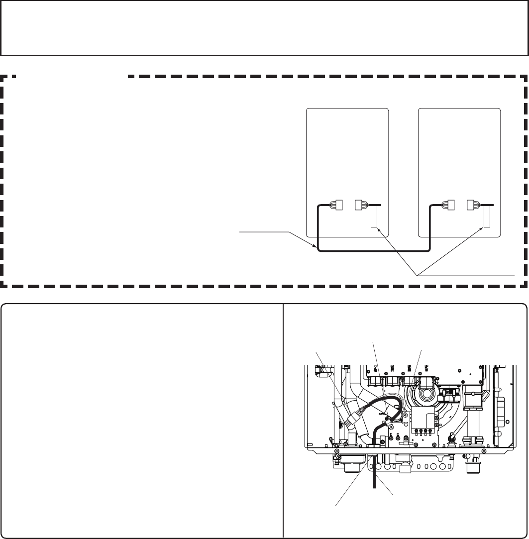
34
Instalación del cable de conexión rápida a las dos
unidades.
1. Apague el aparato.
2. Quite la cubierta frontal del calentador (4 tornillos).
3. Pase el Cable de Conexión Rápida a través de la
entrada de cableado y hacia adentro de la unidad.
4. Enchufe el conector del Cable de Conexión Rápida
al tomacorriente que está dentro de la unidad.
5. Fije el cable a tierra del Cable de Conexión Rápida
a la placa de jación del bloque de terminales.
(Si el cable a tierra no está jado, el ruido eléctrico
puede causar problemas).
6. Asegure el Cable de Conexión Rápida con una
abrazadera.
7. Vuelva a colocar la cubierta frontal.
Instalación del cable de conexión rápida -2
Precaución
Para Instalaciones Multi-sistema de
Conexión Rápida use solamente la pieza
TWHQCCORD. (Vendida por separado)
Cable de Conexión
Rápida -2
"Cable de Conexión
Rápida -2" etiqueta
A B
1.Rojo
2.Negro
3.Blanco
4.Verde
5.Azul
6.Azul
1.Blanco
2.Verde
3.Rojo
4.Negro
5.Azul
6.Azul
1. Rojo
2. Negro
3. Blanco
4. Verde
5. Azul
6. Azul
1. Rojo
2. Negro
3. Blanco
4. Verde
5. Azul
6. Azul
Los colores de los cables en el Cable de Conexión
Rápida-2 no
serán iguales a los del
enchufe de conexión dentro de la unidad.
* El control remoto se puede conectar a la unidad
A o la B. No conecte un control remoto a ambas
unidades.
* Desconecte el control remoto de la unidad A o la
B antes de instalar el Cable de Conexión Rápida.
Entrada de cableado
Cable de acoplamiento
Abrazadera Conector del
cable a tierra
Conector
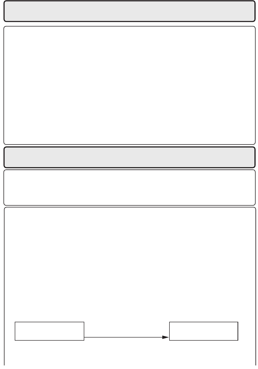
35
(1) Abra el componente de agua caliente y conrme que se enciende el indicador de Quemador
Encendido, y que empieza a salir agua caliente. (Si es necesario, repita esta acción hasta que
salga todo el aire de la tubería de gas).
* Se podrá ver humo blanco salir por el escape cuando el clima es frío. Sin embargo, esto no
es un fallo de la unidad.
*
Si aparece un código de error “11” en el control remoto, apague la unidad y vuélva a
encenderla,
y vuelva a abrir el componente de agua caliente.
(2) Cambie el ajuste de temperatura en el control remoto y compruebe que la temperatura del agua cambia.
r
Si el calentador no funciona normalmente, consulte la seción de “Solución de problemas” en el
Manual de Uso y Cuidado.
* Después de la prueba de funcionamiento, limpie el ltro en la entrada de agua fría.
<Si se instala con un multi-sistema de conexión rápida>
r&ODJFOEBFMTJTUFNBDPOFMDPOUSPMSFNPUP
r"CSB MFOUBNFOUF VO DPNQPOFOUF EF BHVB DBMJFOUF Z DPNQSVFCF RVF MBT VOJEBEFT TF QSFOEFO
secuencialmente. Compruebe que la temperatura del agua caliente es la misma que la
temperatura que aparece en la pantalla del control remoto. (*1)
* Si no se prenden ambas unidades, marque la unidad que se prenderá primero presionando Max. o Min.
en el botón de ajuste de presión de la placa de circuitos. (*2)
* Si aparece parpadeando un código de error 11 o F11 en el control remoto, presione el botón de
encendido/apagado 2 ó 3 veces.
* Si no se puede ejecutar (*1) y (*2), es posible que el Cable de Conexión Rápida no esté bien conectado.
Compruebe que el cable esté conectado correctamente.
14. Mantenimiento
Compruebe periódicamente lo siguiente para asegurar
el funcionamiento adecuado del calentador de agua
r&MTJTUFNBEFWFOUJMBDJÓOEFCFTFSFYBNJOBEPQFSJÓEJDBNFOUFQPSVOUÊDOJDPDBMJàDBEPQBSB
buscar fugas o corrosión.
r-BMMBNBEFMRVFNBEPSTFEFCFDPNQSPCBSQFSJÓEJDBNFOUFQBSBBTFHVSBSRVFNBOUFOHBFMDPMPS
azul y la consistencia.
r4JMBMMBNBOPQBSFDFOPSNBMFTQPTJCMFRVFTFBOFDFTBSJPMJNQJBSFMRVFNBEPS
r4JFTOFDFTBSJPMJNQJBSFMRVFNBEPSMBMJNQJF[BEFCFIBDFSMBVOUÊDOJDPDBMJàDBEP
r/PPCTUSVZBFMáVKPEFMBJSFEFDPNCVTUJÓOZWFOUJMBDJÓO
r-BWBMWVMBEFBMJWJPEFQSFTJÓOTFEFCFVUJMJ[BSBMNFOPTVOBWF[BMBÒPQBSBBTFHVSBSRVFGVODJPOB
correctamente y que no hay obstrucciones. Apague la unidad antes de abrir la válvula de alivio, y
cerciórese de que el drenaje del agua hacia afuera de la válvula no provoque ningún daño.
r
Si la válvula de alivio se descarga periódicamente, puede ser debido a la expansión termal en un
sistema cerrado de agua.
Póngase en contacto con el proveedor de agua o un inspector local de
fontanería para conocer cómo corregir esta situación.
No conecte la válvula de alivio.
r$POTVMUFFMNBOVBMEFVTPZDVJEBEPQBSBNÃTJOTUSVDDJPOFTEFNBOUFOJNJFOUP
"EWFSUFODJB
Existe un alto riesgo de quemaduras si la temperatura de salida está ajustada en alto.
En caso de sobrecalentamiento, o si el suministro de gas no se detiene, cierre la válvula manual de control de gas del aparato.
No utilice este aparato si alguna de sus partes ha estado bajo el agua. Llame inmediatamente a un técnico
calicado
para inspeccionar el aparato y cambie cualquier pieza del sistema de control y del control de
gas que haya estado bajo el agua..
Compruebe periódicamente y limpie el ltro dentro de la entrada de agua fría de la unidad.
15. Prueba de funcionamiento
El instalador debe comprobar al funcionamiento de la
unidad, explicar al cliente como usarla, y dar al dueño
este manual antes de concluir la instalación.
Se prende la unidad A
No se prende la unidad B
Presione Max. o Min. en el
botón de ajuste de presión en
la unidad B
No se prende la unidad A
Se prende la unidad B
r 1SFQBSBDJÓO "CSB FM DPNQPOFOUF EF BHVB DBMJFOUF QBSB DPOàSNBS RVF IBZ BHVB Z
cierre el componente.
(2) Abra la válvula de suministro de gas.
(3) Encienda el aparato. Usando el control remoto, encienda el aparato a través del
Botón de Encendido/Apagado (se encenderá el indicador de funcionamiento)
36
Instrucciones de encendido
Este calentador de agua no cuenta con un piloto. Está equipado con un dispositivo de encendido
que prende el quemador automáticamente.
No trate de prender el quemador con las manos.
1. Lea la información de seguridad en el manual de instalación o en la parte frontal del calentador
de agua.
2. Desconecte la alimentación de la unidad
3. No intente prender el quemador con las manos.
4. Gire la válvula manual de control de gas (externa a la unidad) en el sentido de las agujas del reloj
a la posición de cerrada.
5.
Espere 5 minutos para que salga todo el gas. Si se mantiene el olor a gas, deténgase y siga las
instrucciones
de la página 3 del Manual de Uso y Cuidado.
6. Gire la válvula manual de control de gas en sentido contrario a las agujas del reloj a la posición
de abierta.
7. Conecte la alimentación de la unidad
8. Ahora la unidad funcionará siempre que se abra una llave de agua caliente. Si la unidad no
funciona, siga las instrucciones de apagado y llame a un técnico de mantenimiento.
Instrucciones de apagado
1. Detenga la demanda de agua.
2. Apague el aparato.
3. Gire la válvula manual de control de gas en el sentido de las agujas del reloj a la posición de
cerrada.
En caso de sobrecalentamiento, o si el suministro de gas no se detiene, cierre la válvula manual de control de
gas del aparato.
Manejo después de la prueba de funcionamiento
Si la unidad no se va utilizar inmediatamente, cierre todas las válvulas de gas y agua, drene
toda el agua hacia afuera de la unidad y del sistema de tuberías para evitar que la unidad y
el sistema se congelen, y vacíe la línea de gas.
El congelamiento no está cubierto en la garantía
PRECAUCIÓN
Si estas instrucciones no se siguen pueden ocurrir incendios o explosiones, que pueden
causar la pérdida de vidas, lesiones personales o daños materiales.
ADVERTENCIA:

37
16. Dimensiones
< pulgada (mm)>
ALTURA DE CADA ACCESORIO
DESDE EL FONDO DE LA CAJA
DESAGUE DE CONDENSACIÓN
SALIDA DE AGUA CALIENTE
ENTRADA DE AGUA FRIA
ENTRADA DE GAS
0.8" (20mm)
1.7" (44mm)
2.2" (55mm)
2.2" (56mm)
(VISTA DESDE ARRIBA)
EN19WI30LS
EP19WI30LS
SALIDA DE AGUA CALIENTE (3/4")
DESAGUE DE CONDENSACIÓN (1/2")
ENTRADA DEL CABLEADO
ENTRADA DEL CABLEADO
(AC120V)
ENTRADA DE AGUA FRIA (3/4")
ENTRADA DE GAS (3/4")
5.3" (135mm)
6.1" (155mm)
4.3" (109mm)
2.4" (60mm)
6.7" (171mm)
7.0" (177mm)
8.4" (214mm)
3.9" (99mm)
2.8" (70mm)
14.2" (362mm)
5.7" (146mm)
3.9" (98mm)
VALVULA DE DESAGUE
ENTRADA DE AGUA FRIA
VALVULA DE DESAGUE
SALIDA DE AGUA CALIENTE
VALVULA DE DESAGUE
DESAGUE DE CONDENSACIÓN
ENTRADA DEL CABLEADO
ENTRADA DE GAS
VALVULA DE DESAGUE
(FILTRO DE AGUA)
ENTRADA DEL CABLEADO
(AC120V)
ENTRADA DE AIRE
COLLAR DE LA CHIMENEA
24.4" (619mm)
Ø4.5" (Ø114mm)
Ø3.5" (Ø89mm)
17.7" (450mm)
18.4" (468mm)
17.6" (448mm)
5.9" (150mm) 9.1" (232mm)
Ø4.5" (Ø114mm)
Ø3.5" (Ø89mm)
6.7" (170mm)
5.5" (140mm)
3.9" (100mm)
2.8" (70mm)
1.4" (36mm) 0.4" (10mm)
4 - Ø0.5" (Ø13mm)
6 - 0.24" x 0.4" (6 x 10mm) AGUJERO ALARGADO
1.6" (40mm)
26.2" (665mm)
23.1" (586mm)
2.4" (61mm)
0.4" (10mm) 9.4" (240mm)
5.5" (140mm)
1.1" (28mm
4 - Ø0.5" (Ø13mm)
6 - 0.24" x 0.4" (6 x 10mm) AGUJERO ALARGADO
6.7" (170mm)
5.5" (140mm)
3.9" (100mm)
2.8" (70mm)
1.4" (36mm)
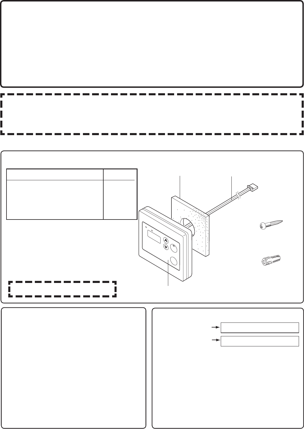
38
Listado de piezas incluidas
Para instaladores:
Lea la guía de instalación
cuidadosamente antes de
hacer la instalación.
Nota
No conecte la la fuente de alimentación al calentador hasta que no se haya instalado
correctamente el control remoto. La ubicación de instalación recomendada para el control remoto
es el cuarto de baño.
No desmonte el control remoto
Relleno de pared Cable de conección
Control remoto
Tornillo phillips
cabeza redonda
Anclaje de pared
Nombre de la pieza
Control remoto
Relleno de pared
Tornillo phillips cabeza redonda
Anclaje de pared
Cantidada
1
1
2
2
Notas sobre el lugar de instalación
r&M SFNPUP TF EFCF JOTUBMBS FO VO MVHBS EF
fácil acceso.
r
Evite hacer la instalación en un lugar donde el
agua o el vapor puedan entrar en contacto con
el control.
r&WJUFMVHBSFTEPOEFTFVTFOBHFOUFTRVÎNJDPT
especiales (por ejemplo, benceno, detergentes
grasos y oleaginosos).
r&W JU F MB JOT UB MBD JÓO F O FY UFS J PSFT P
instalaciones en interiores donde pueda
estar expuesto a la luz solar.
Conexión del cable del control remoto
Conector blanco
Para el control remoto
5FSNJOBMFT: 1BSBFMDBMFOUBEPSEFBHVB
(dos núcleos)
* Conrme la conexión con las etiquetas a
ambos extremos del cable del control remoto.
r
El cable del control remoto se puede extender
hasta 300 pies (90m). empalmandolo y
usando un cable calibre 18 para extenderlo
hasta la longitud adecuada.
Control remoto
Guía de instalación
Electrolux Home Products, Inc.
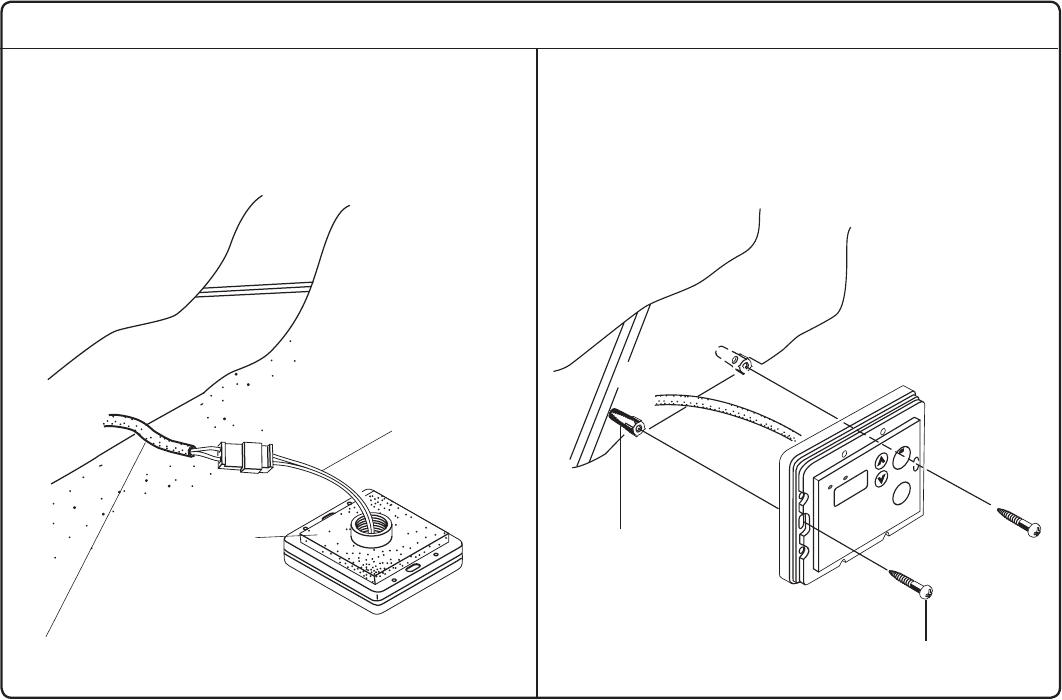
39
Instalación
1. Aplique relleno de pared a la parte posterior
del control remoto.
2. Conecte los cables del control remoto al
cable de otro control remoto.
Cabeza redonda phillips
Tornillo para madera
Anclaje de pared
3. Quite la cubierta del control remoto, marque
la ubicación de los orificios para tornillos, y
taladre los oricios para el anclaje de pared.
4. Introduzca el anclaje de pared, atornille el
control remoto a la pared y vuelva a colocar
la cubierta.
Cable del control remoto
Relleno de pared
(quite el papel)
Control
remoto
Cables
Parte posterior del
control remoto

