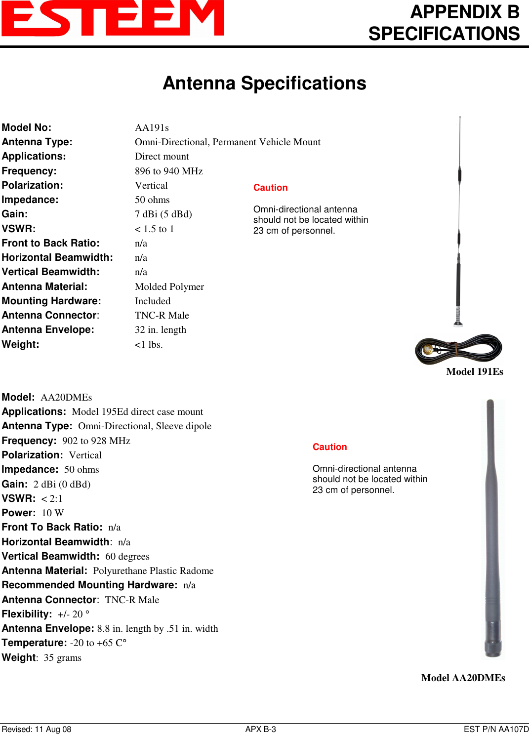
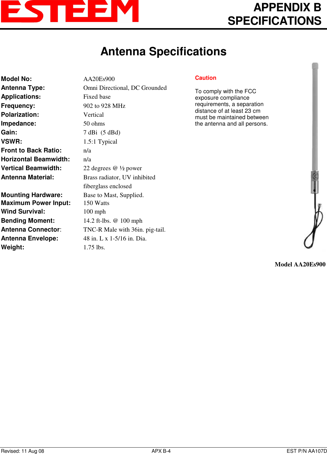
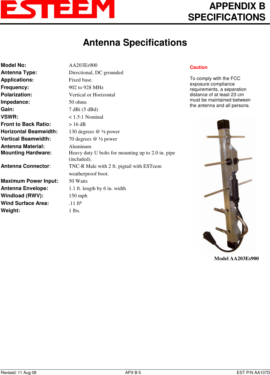
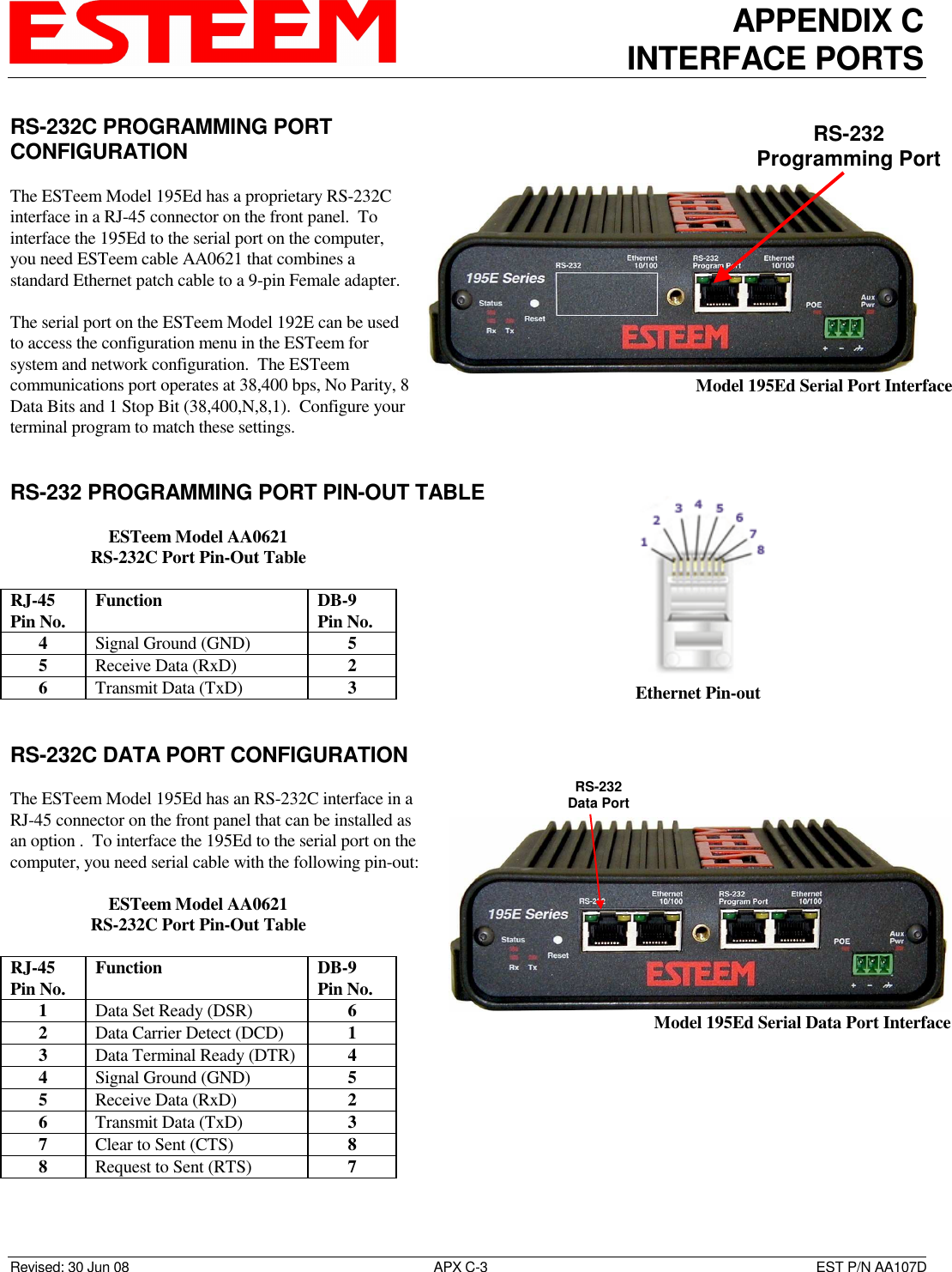
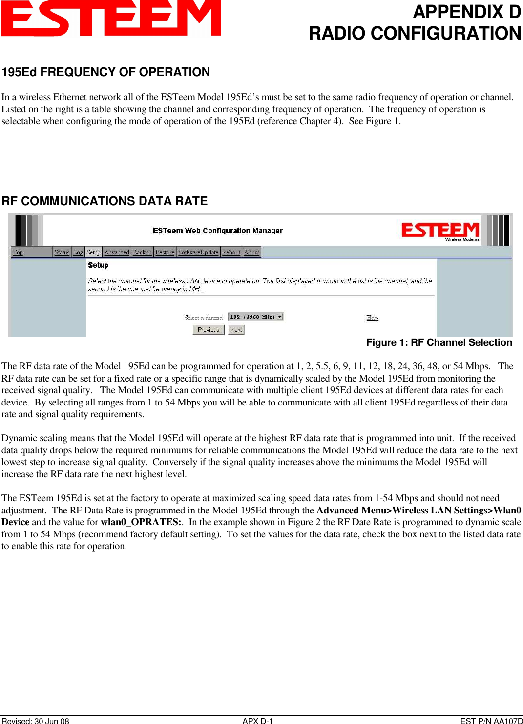
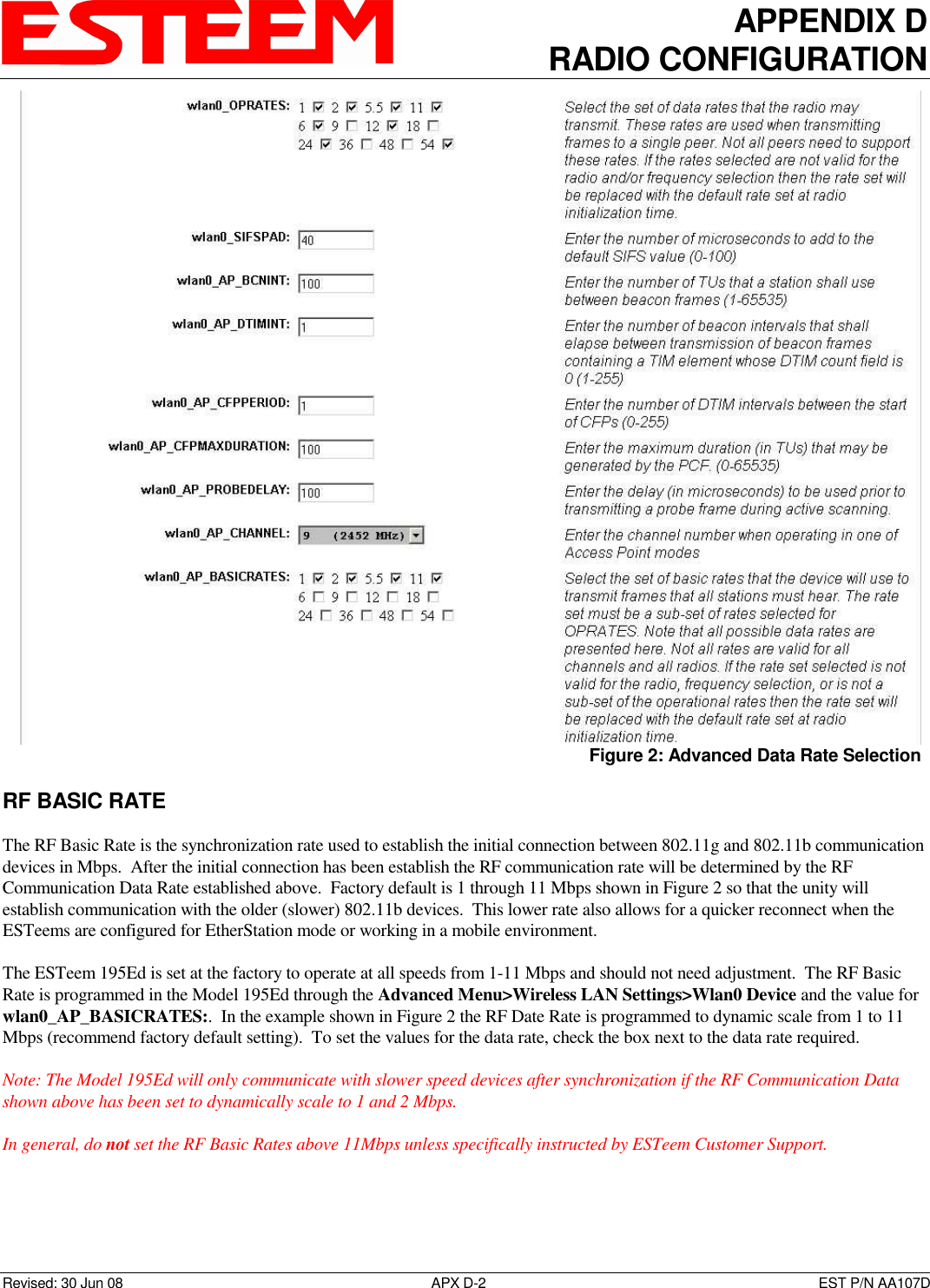
Electronic Systems Technology ESTEEM195ED-1 Wireless LAN transceiver User Manual 195Ed Chapter 0 Front Cover 195Ed
Electronic Systems Technology Wireless LAN transceiver 195Ed Chapter 0 Front Cover 195Ed
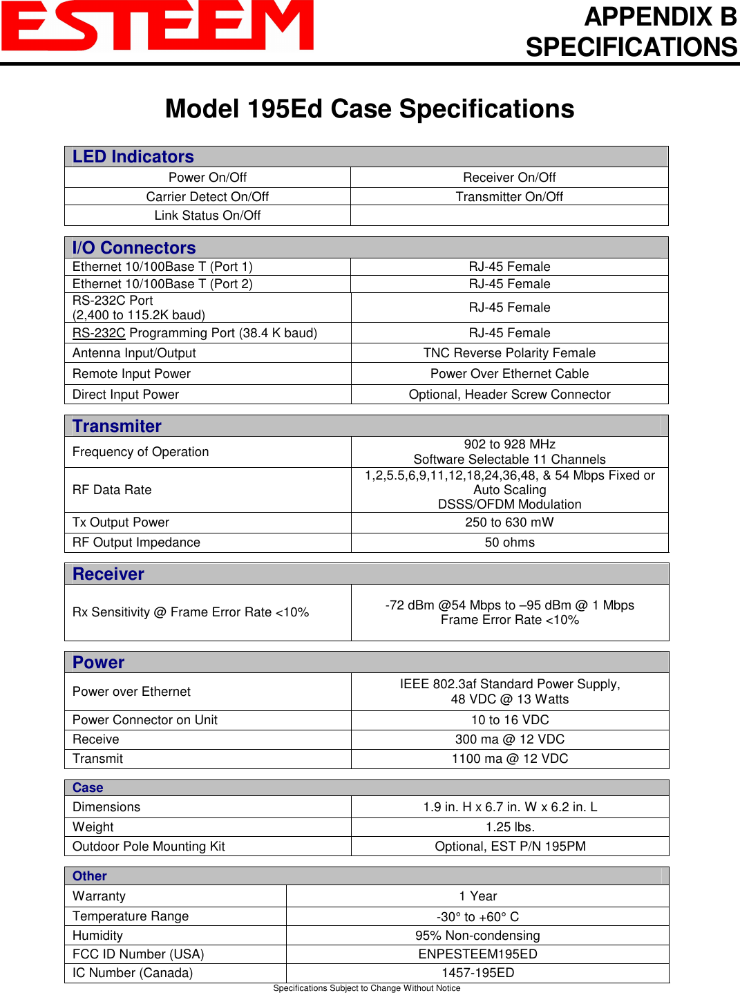
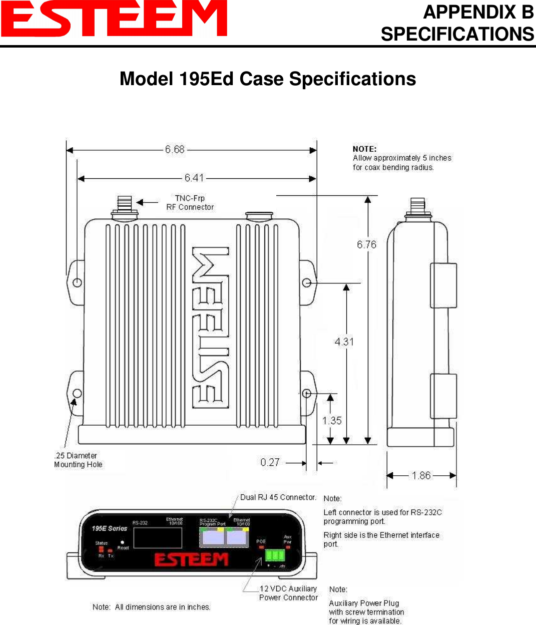
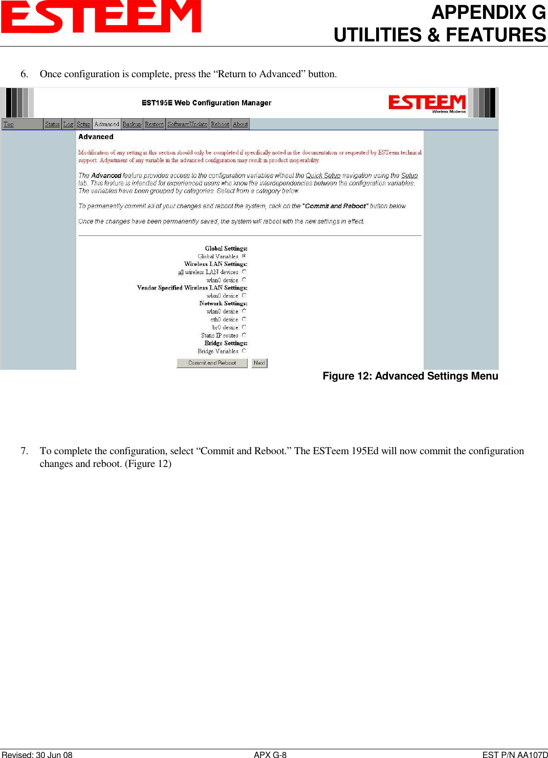
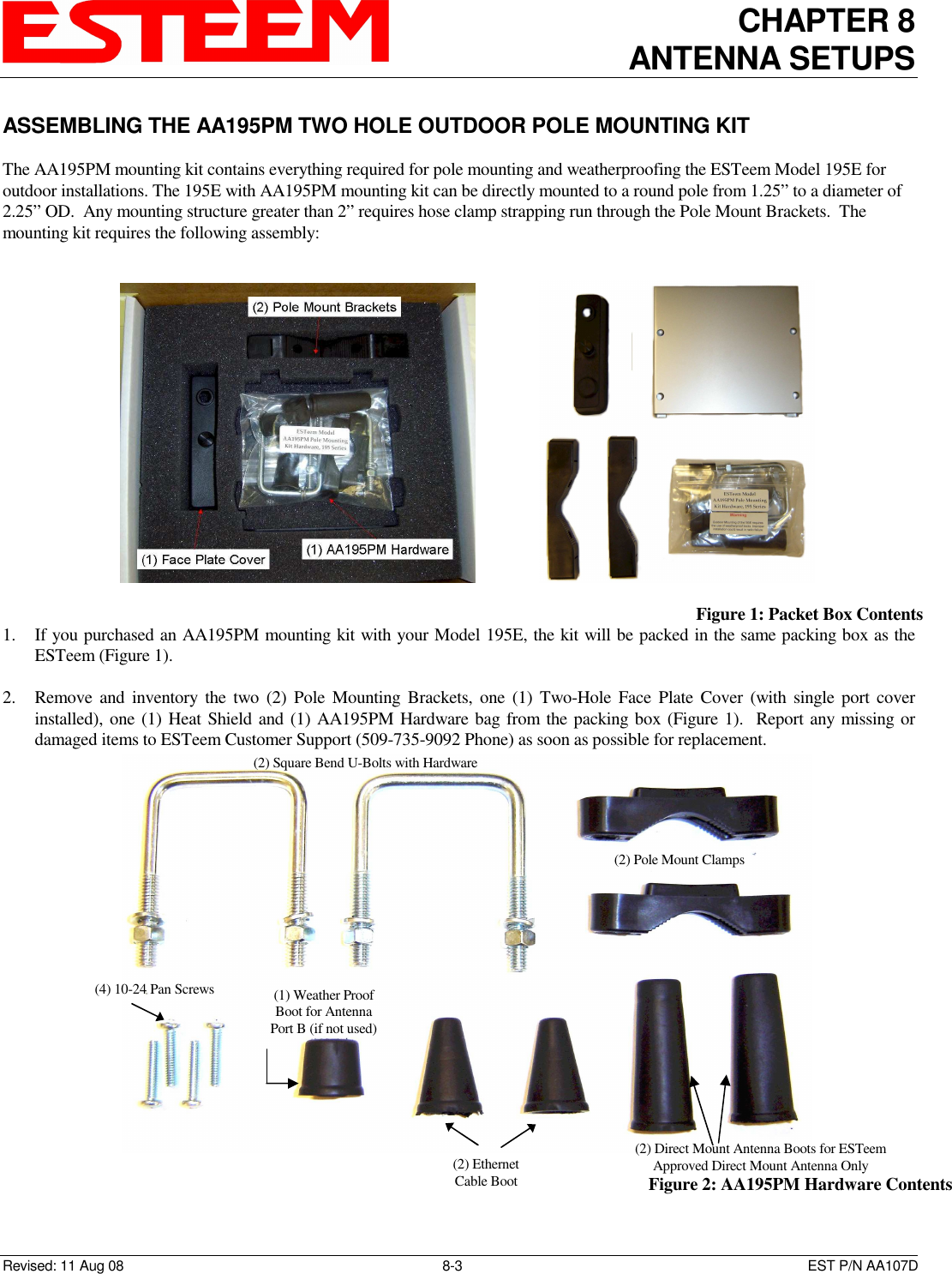
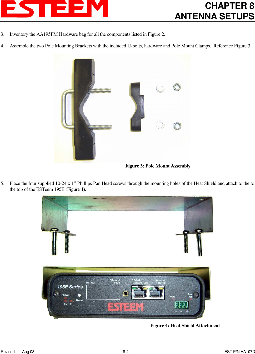
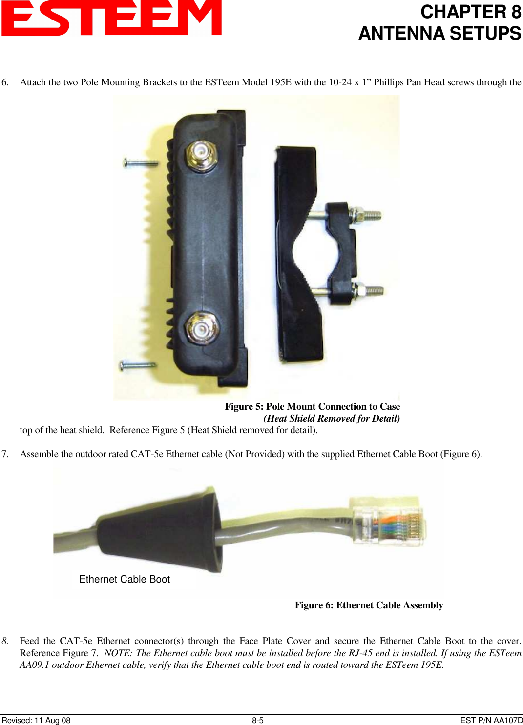
Contents
- 1. User Manual - Part 1
- 2. User Manual - Part 2
- 3. User Manual - Part 3
- 4. Test Setup Photos
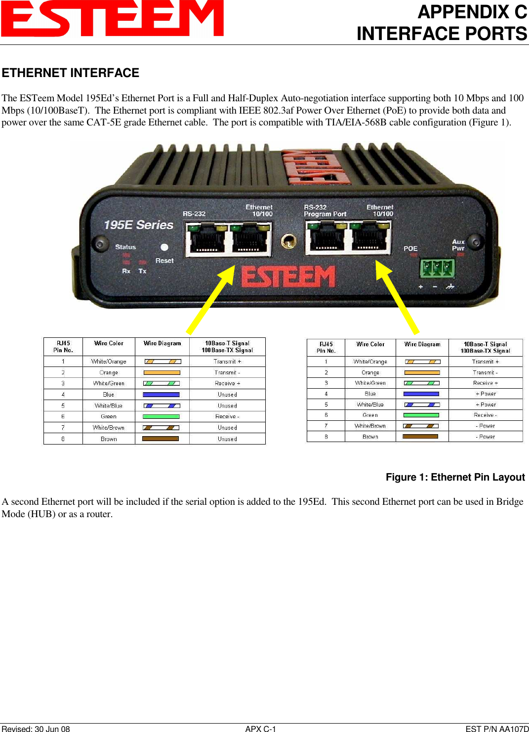
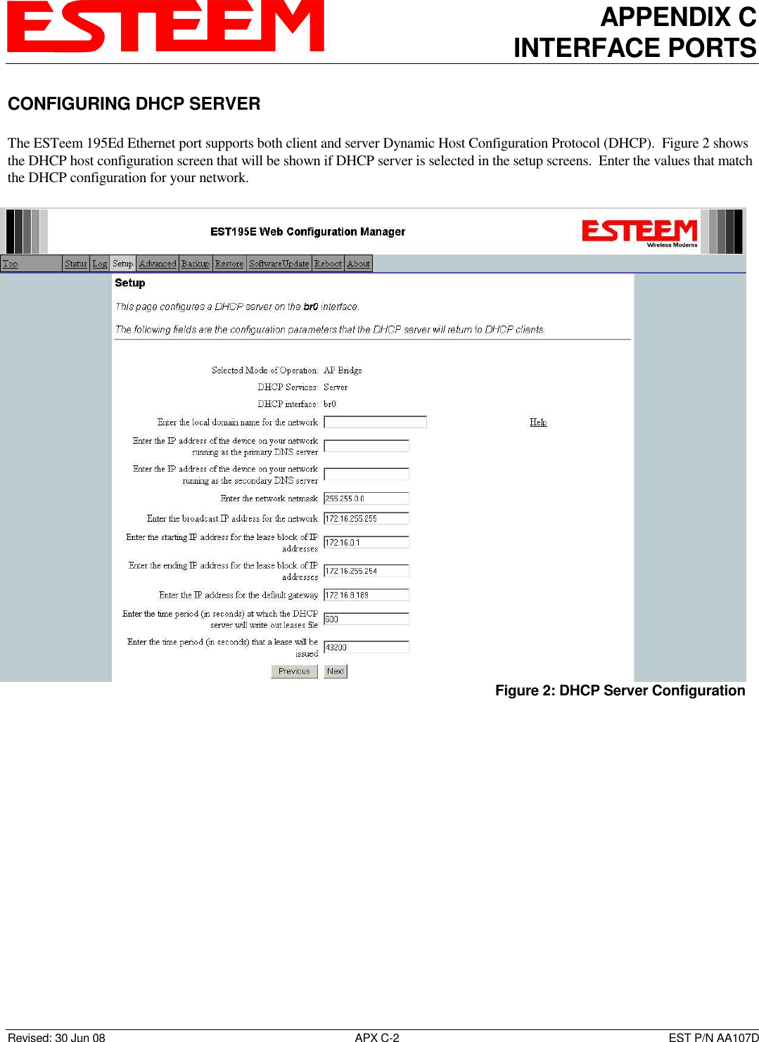
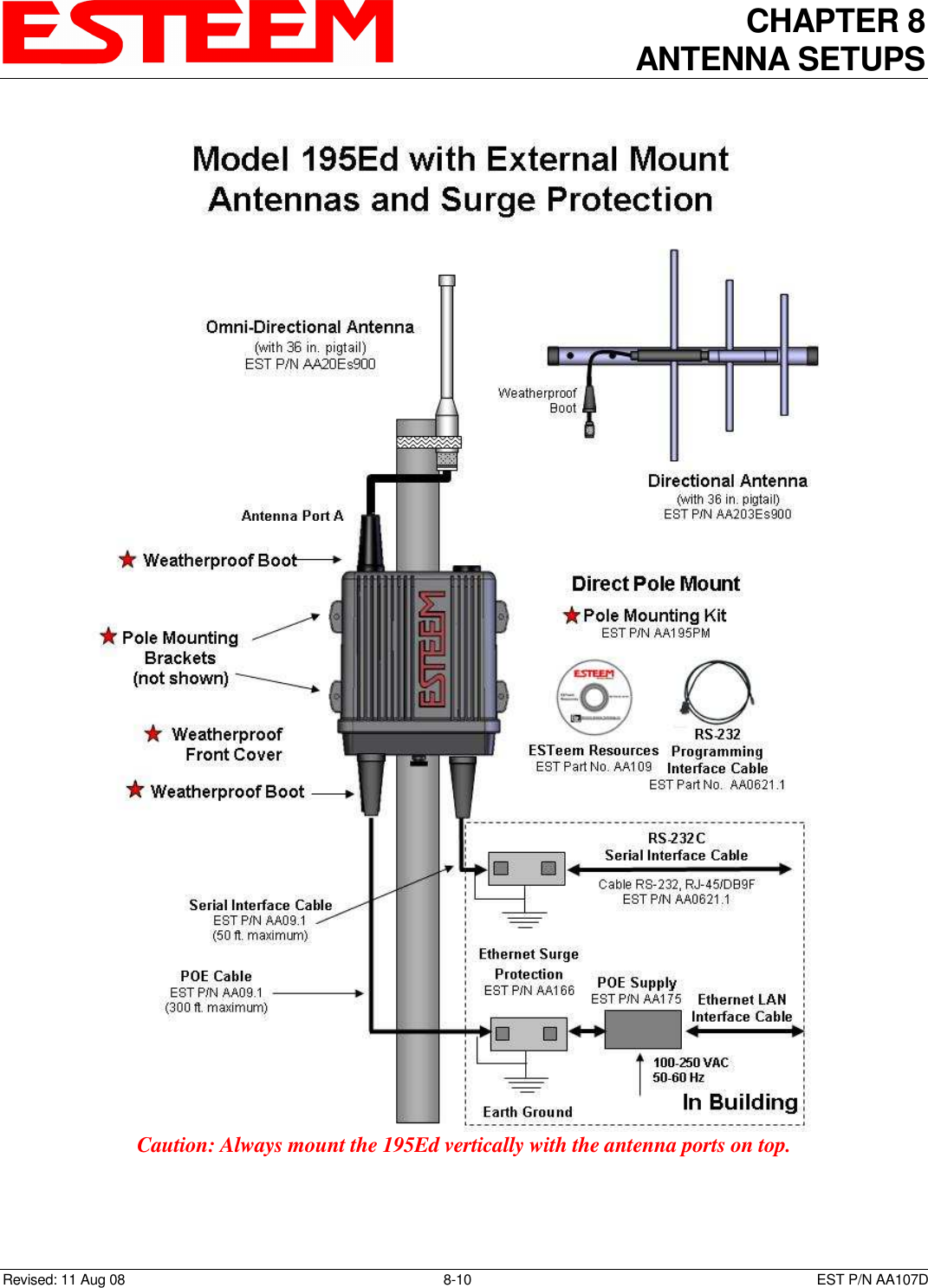
User Manual - Part 3
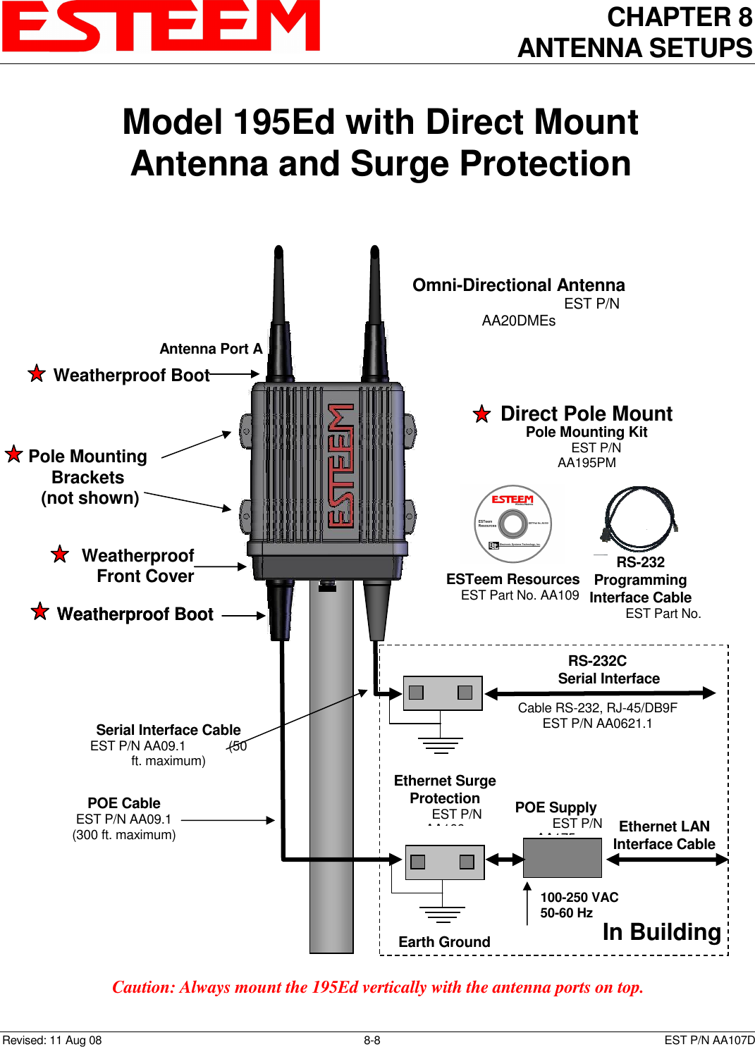
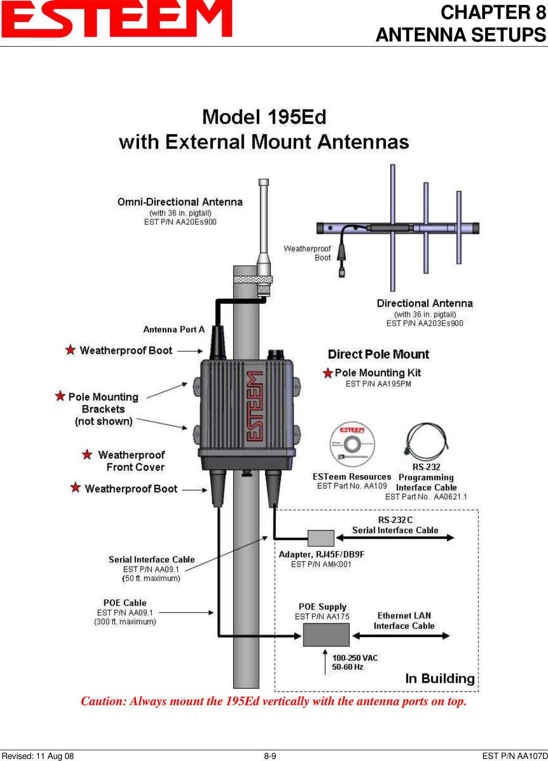
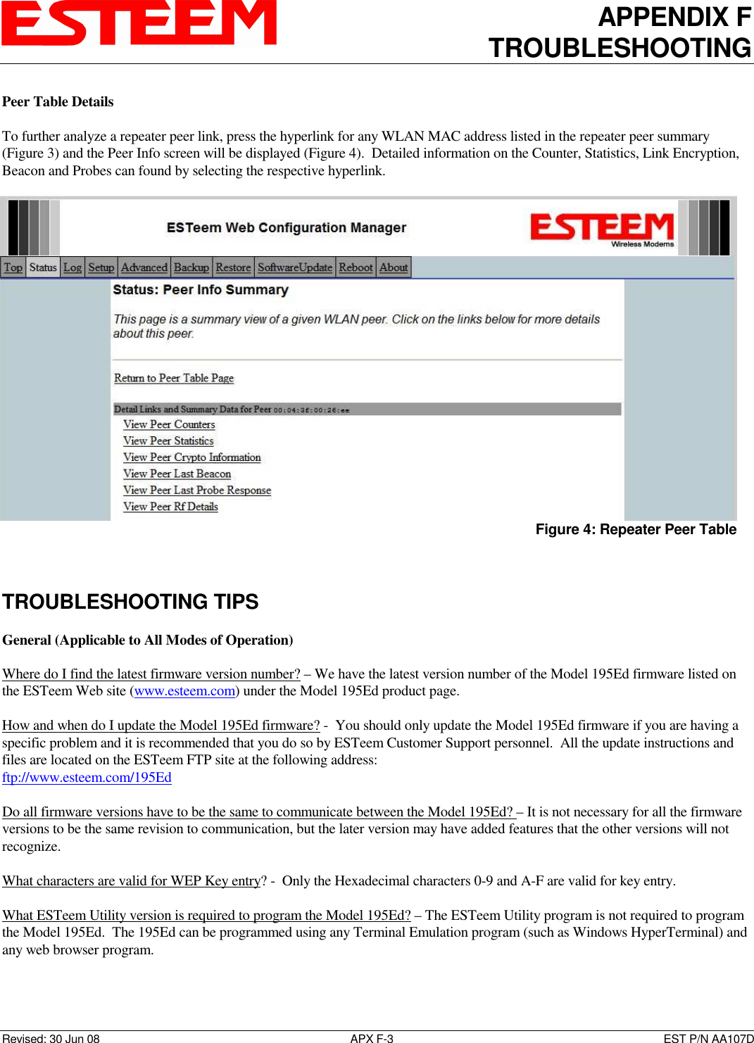
![CHAPTER 8 ANTENNA SETUPS Revised: 11 Aug 08 8-11 EST P/N AA107D FRESNEL ZONE The Fresnel zone shows the ellipsoid spread of the radio waves around the visual line-of-sight after they leave the antenna (see figure above). This area must be clear of obstructions or the signal strength will be reduced due to signal blockage. Typically, 20% Fresnel Zone blockage introduces little signal loss to the link. Beyond 40% blockage, signal loss will become significant. This calculation is based on a flat earth. It does not take into account the curvature of the earth. It is recommended for RF path links greater than 7 miles to have a microwave path analysis done that takes the curvature of the earth and the topography of the terrain into account. Fresnel Zone Radius = 72.1 SQRT [(d1d2) / (F(d1 + d2)] Units Fresnel Zone Radius in feet. d1 and d2 in statue miles F in GHz](https://usermanual.wiki/Electronic-Systems-Technology/ESTEEM195ED-1.User-Manual-Part-3/User-Guide-1437082-Page-9.png)