Electronic Systems Technology ESTEEM195ED Wireless LAN transceiver User Manual 195Ed Chapter 0 Front Cover 195Ed
Electronic Systems Technology Wireless LAN transceiver 195Ed Chapter 0 Front Cover 195Ed
Contents
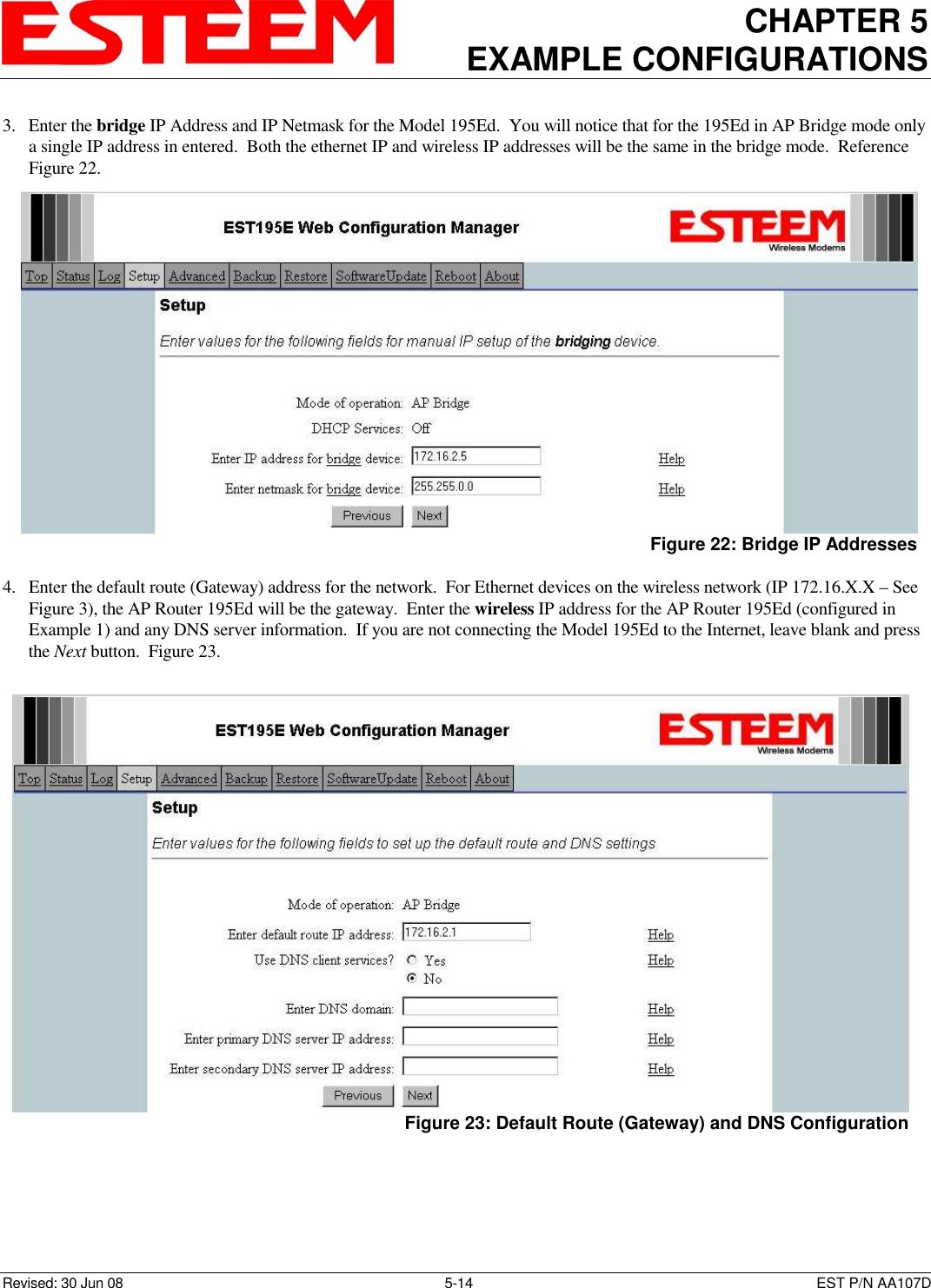
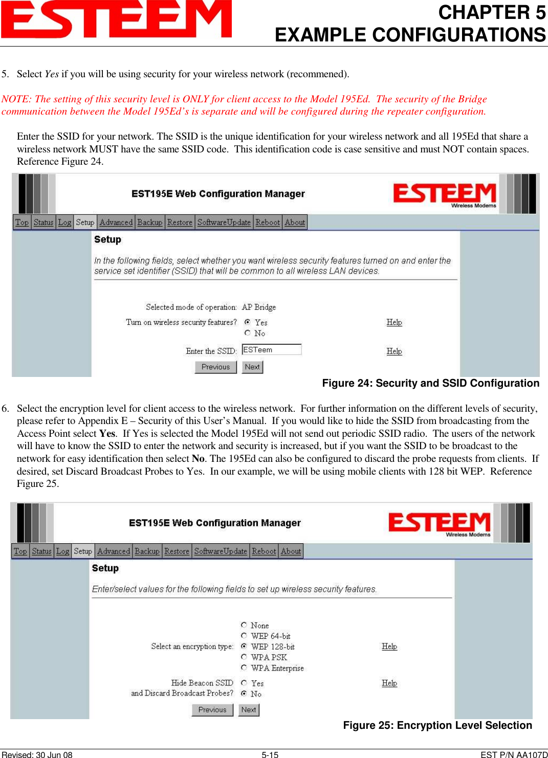
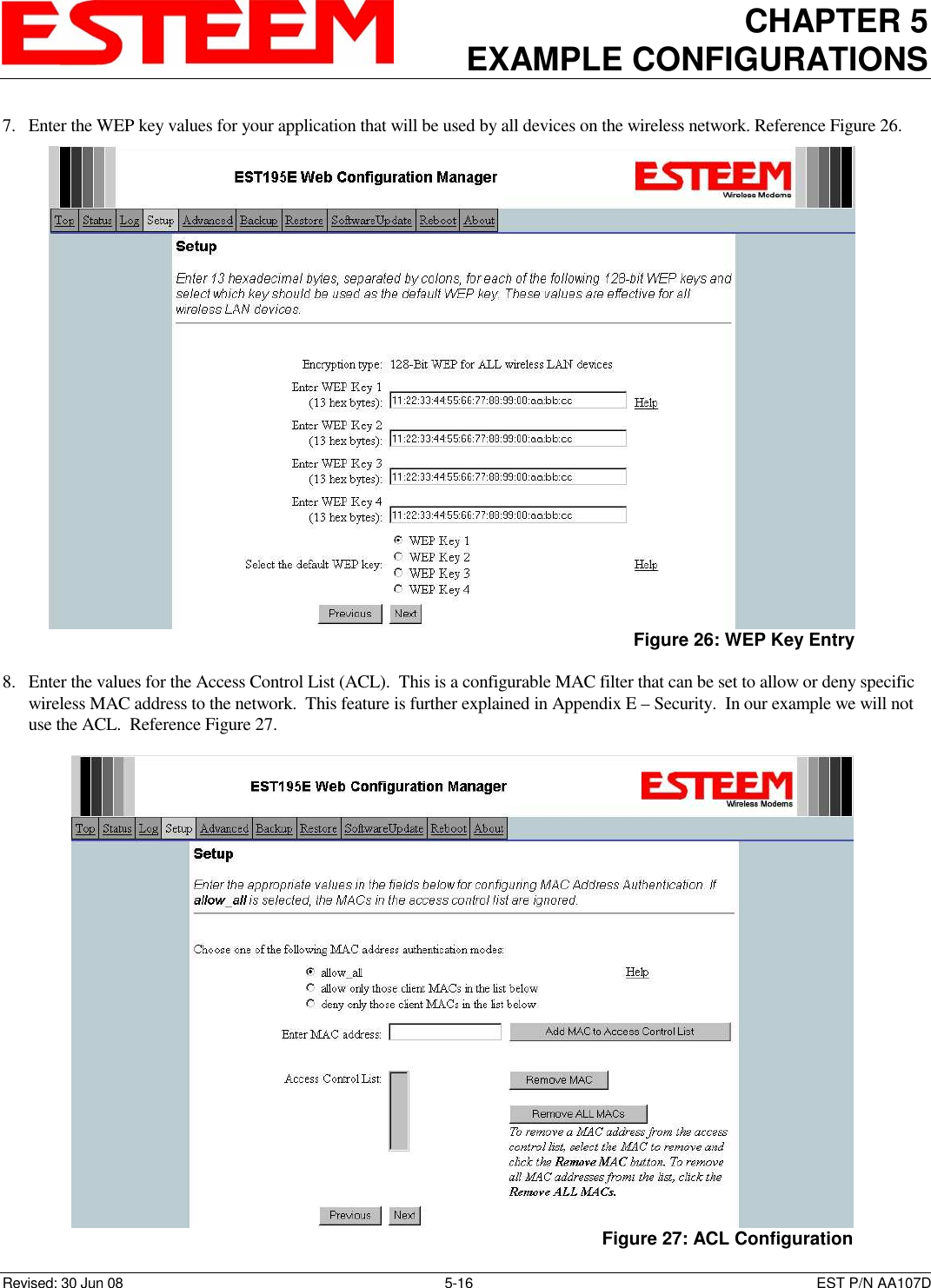
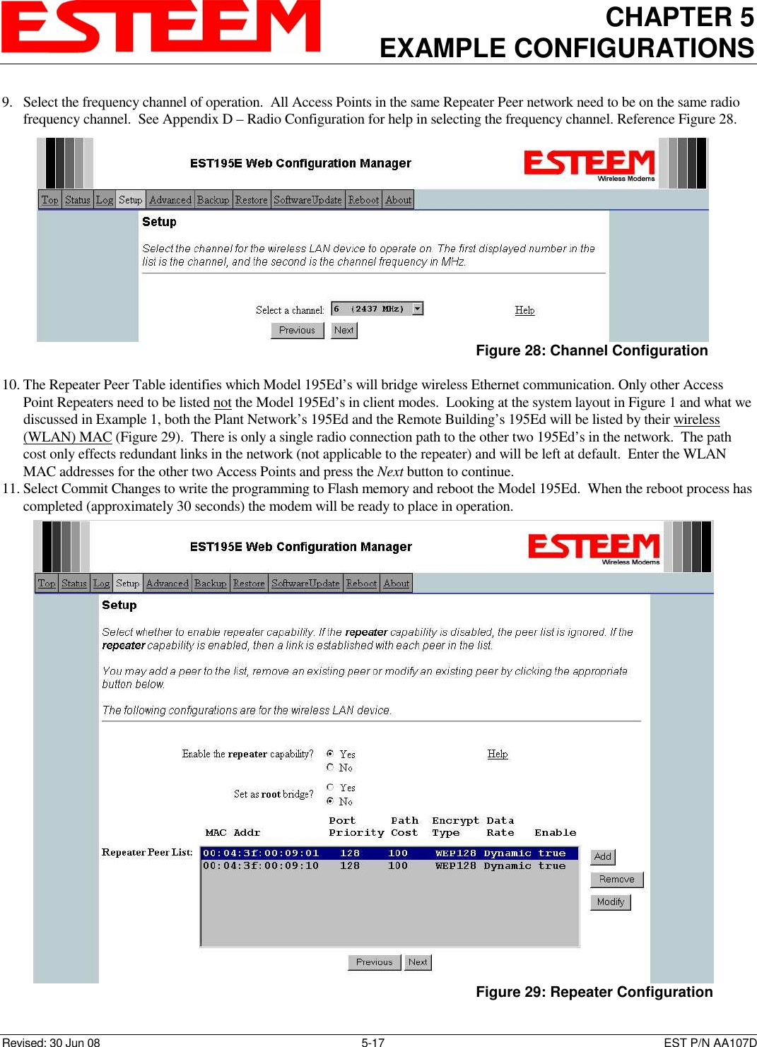
- 1. Manual Part 1
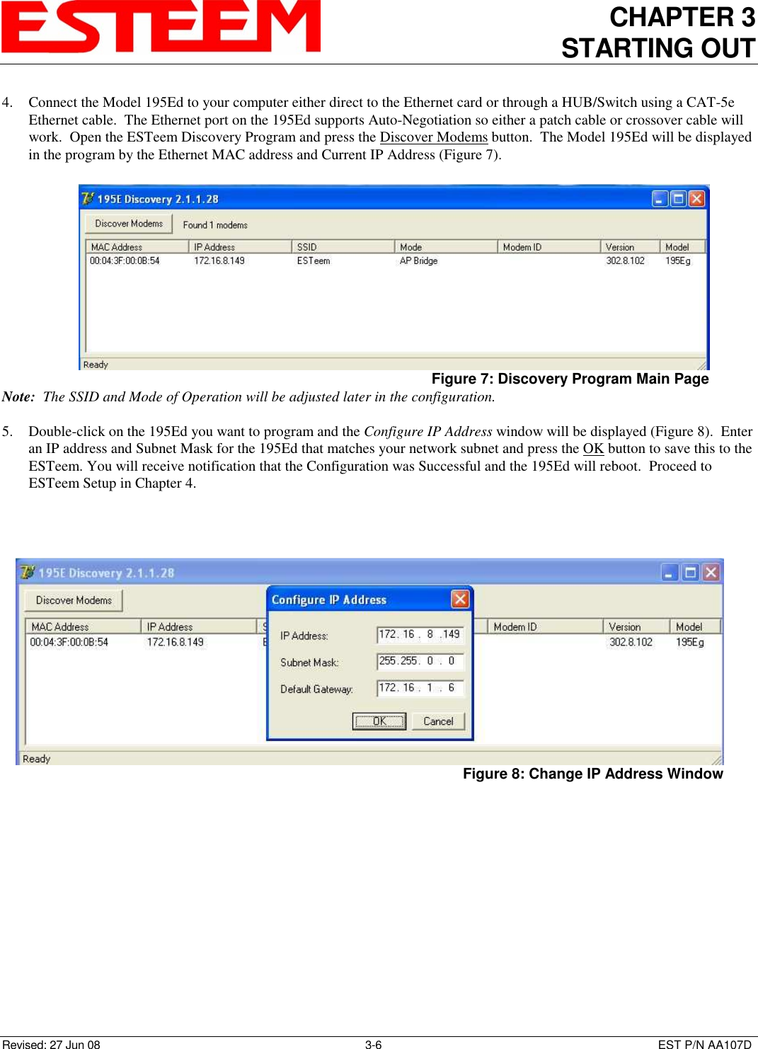
- 2. Manual Part 2
- 3. Manual Part 3
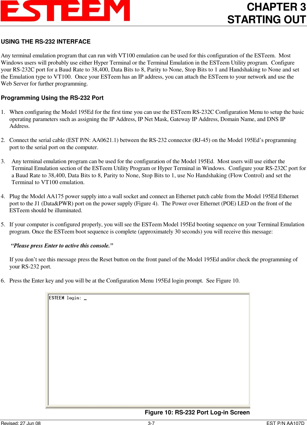
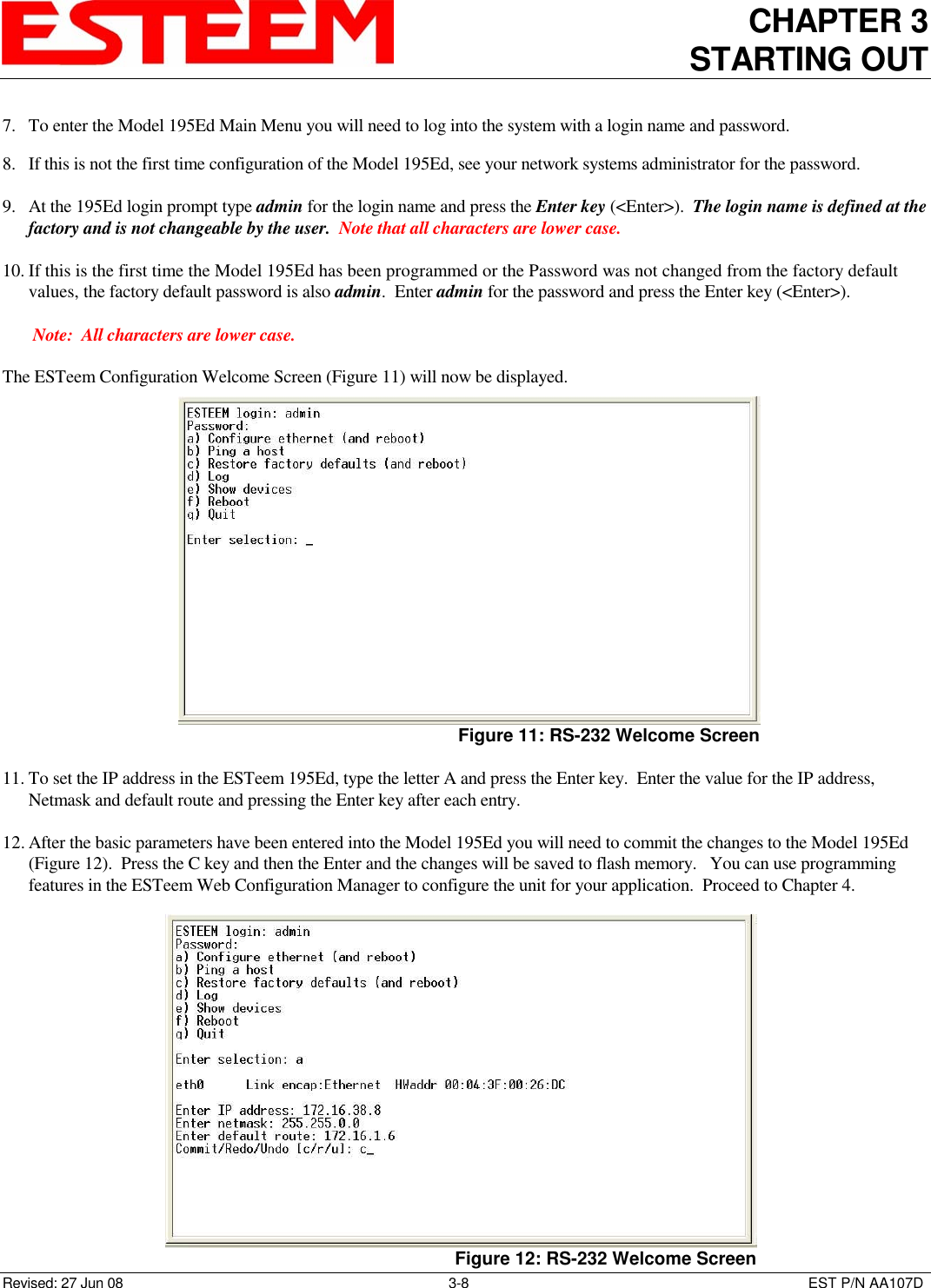
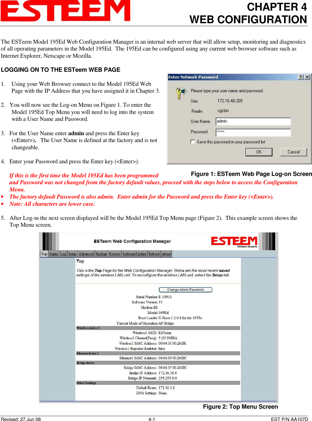
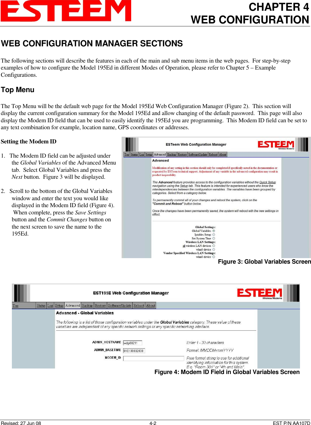
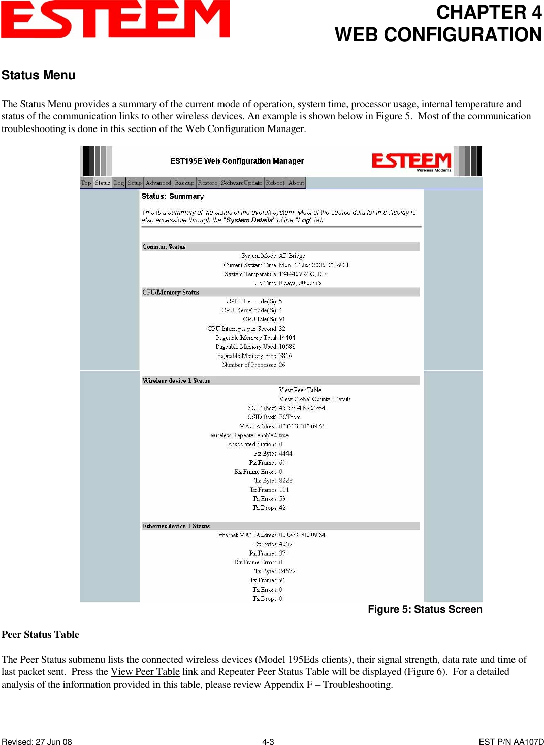
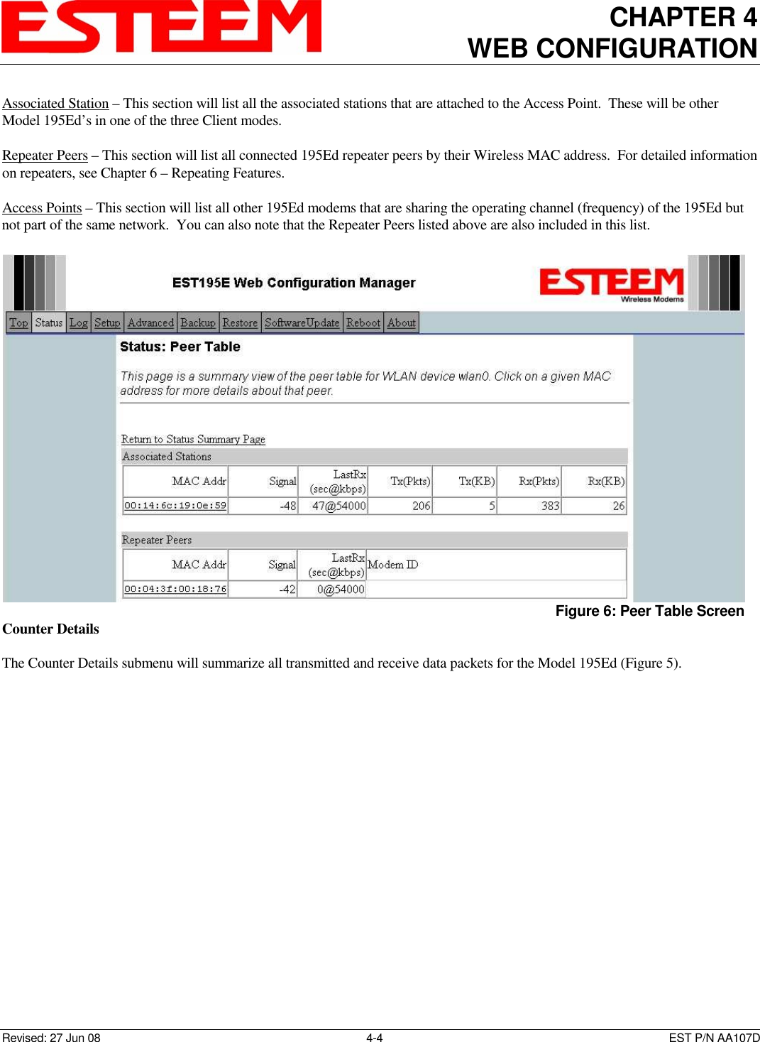
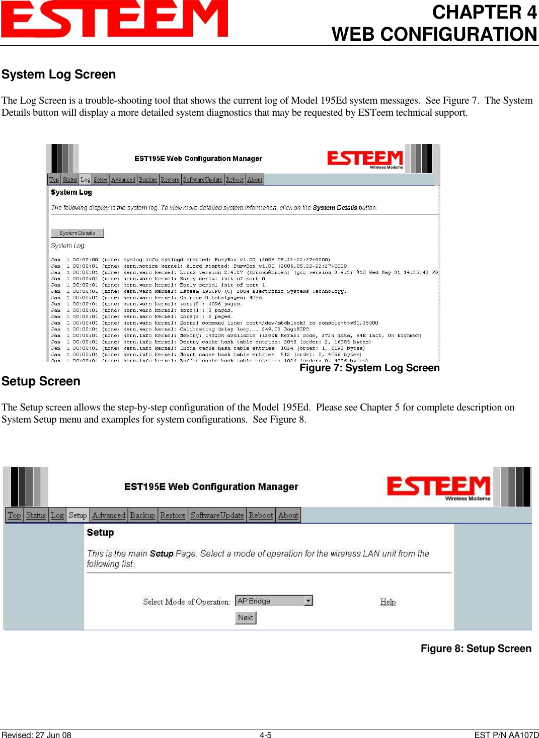
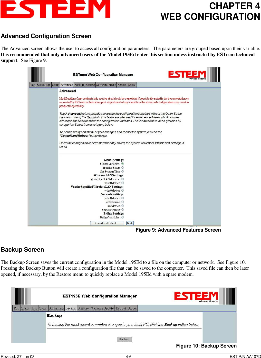
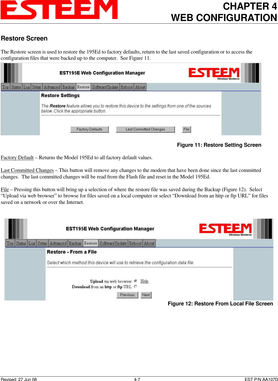
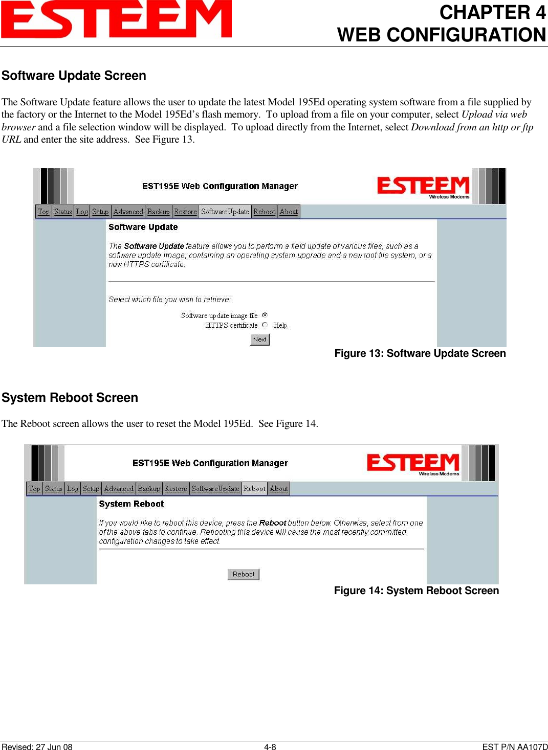
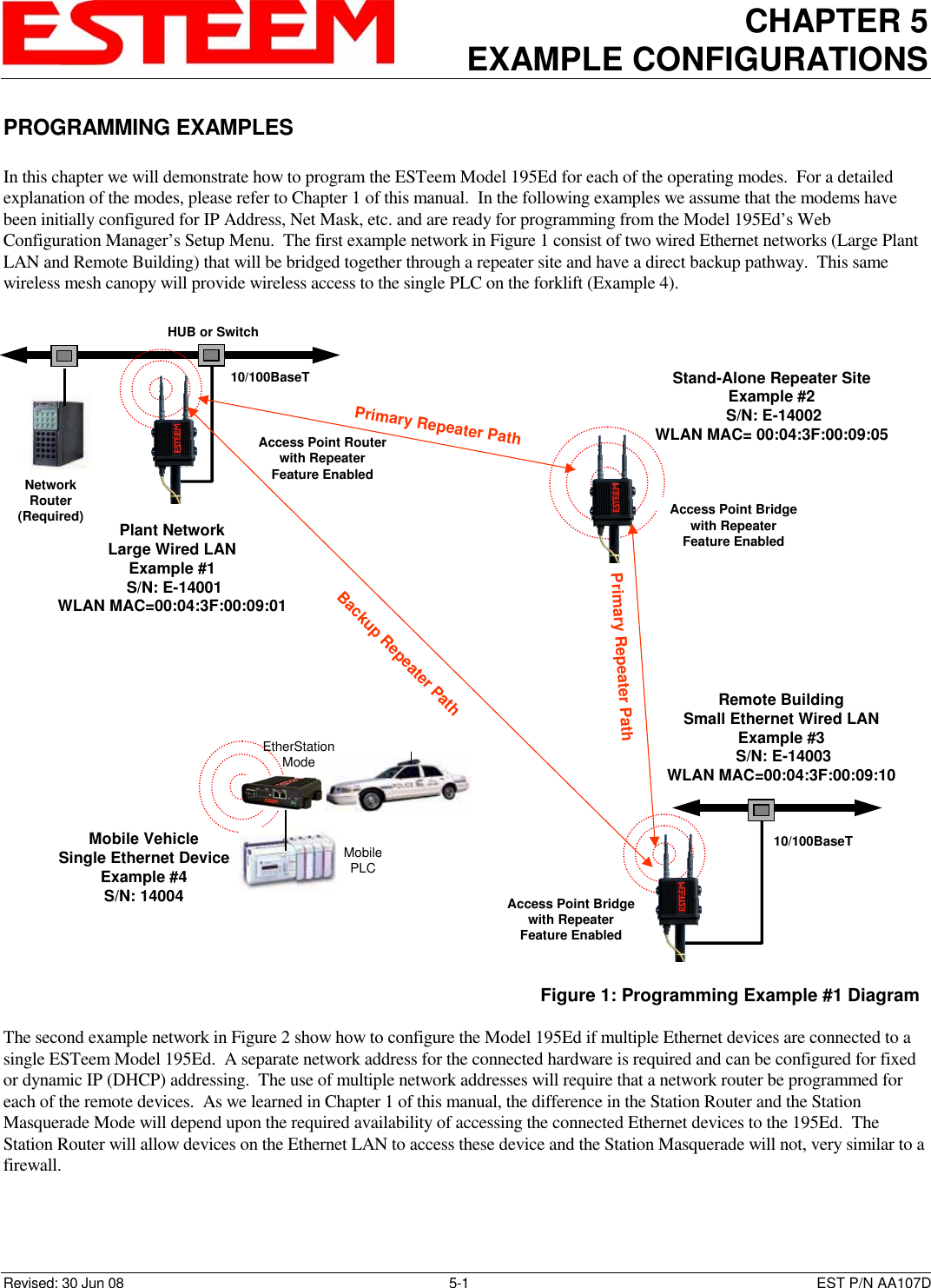
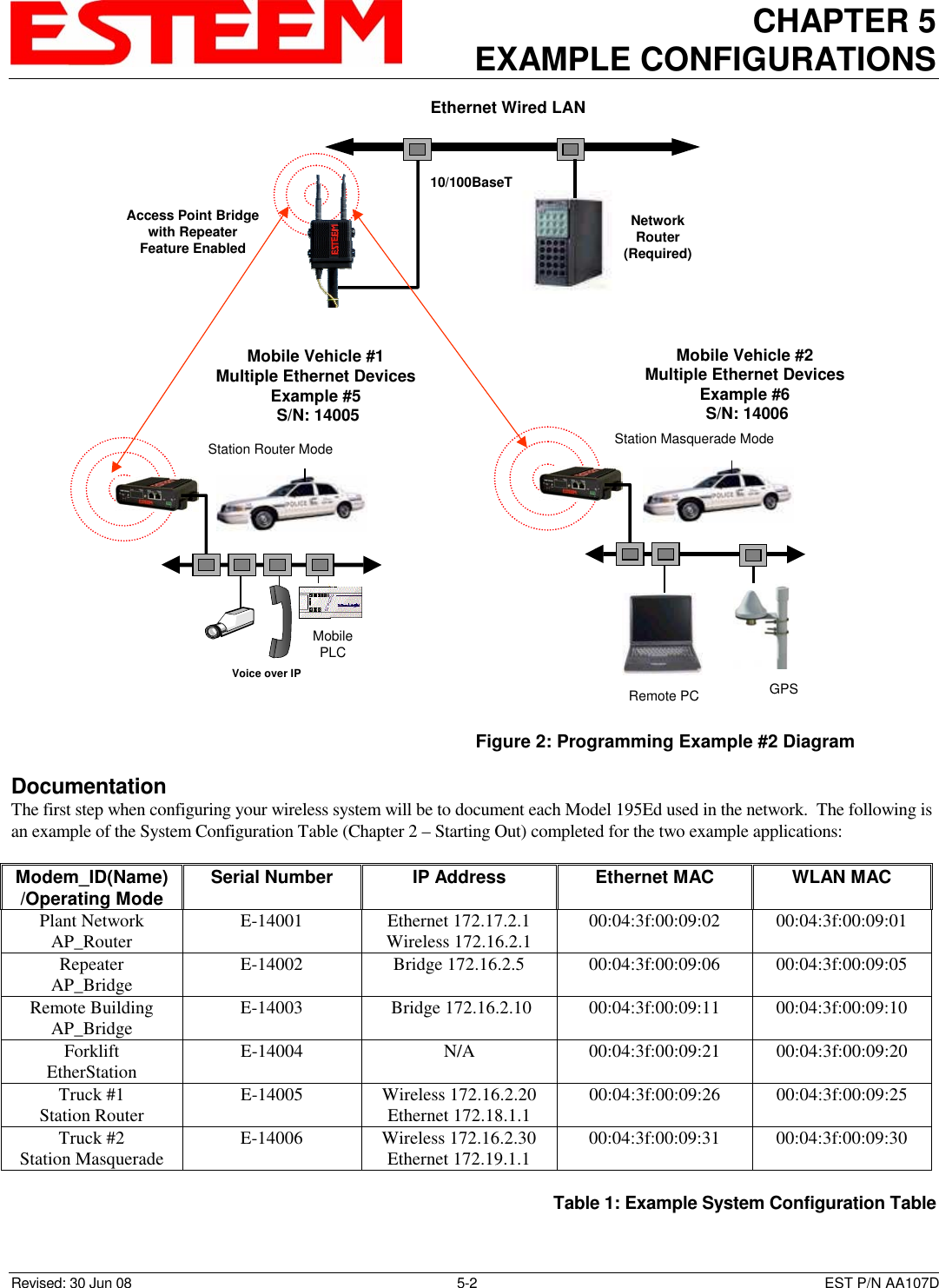
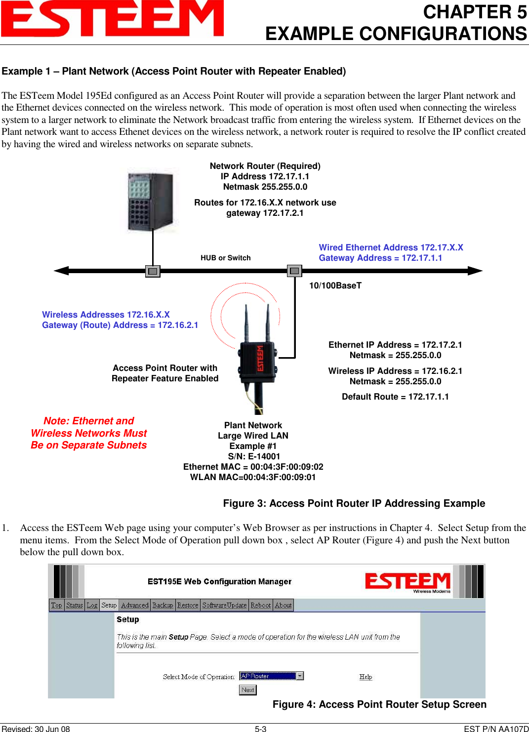
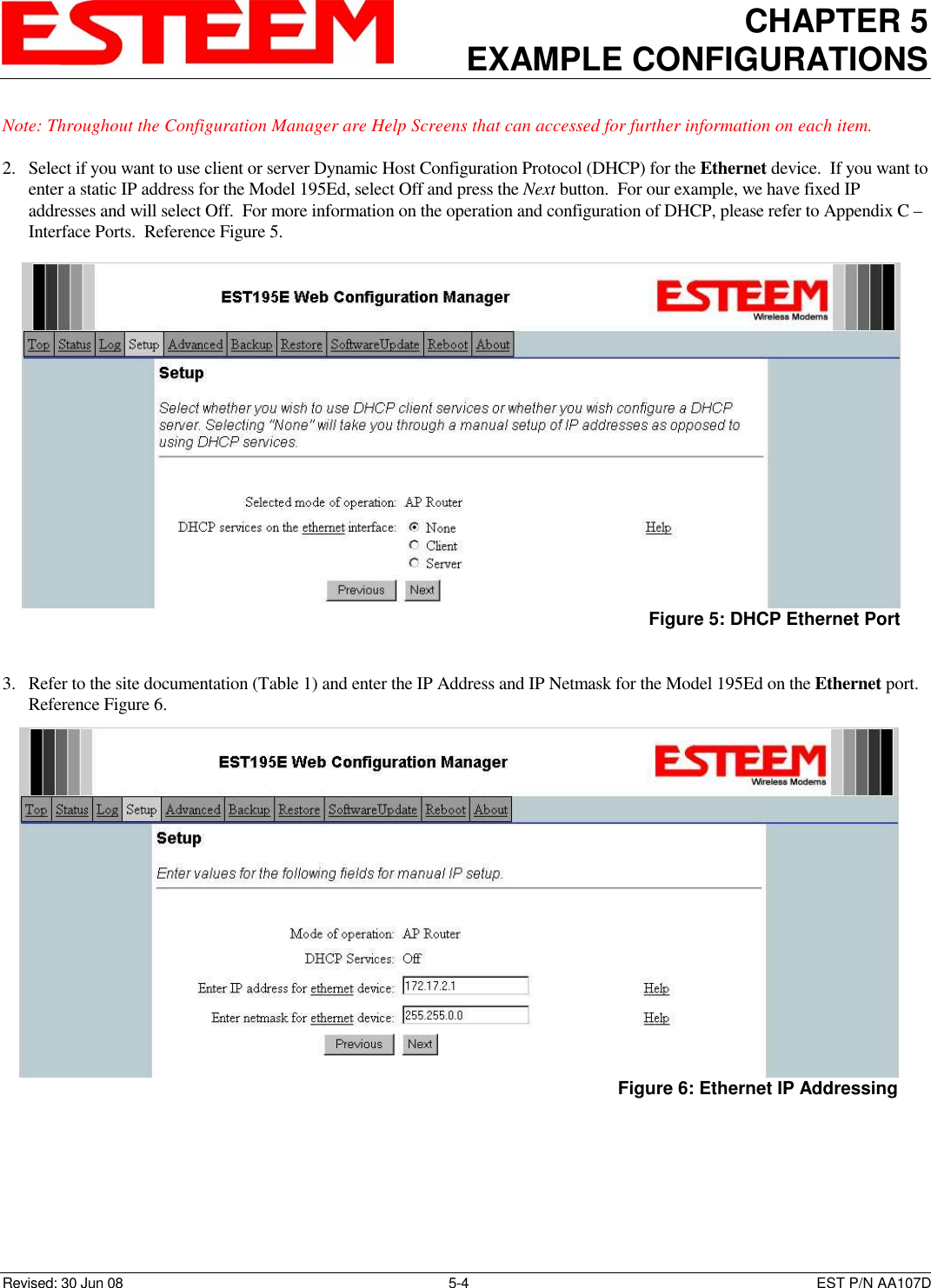
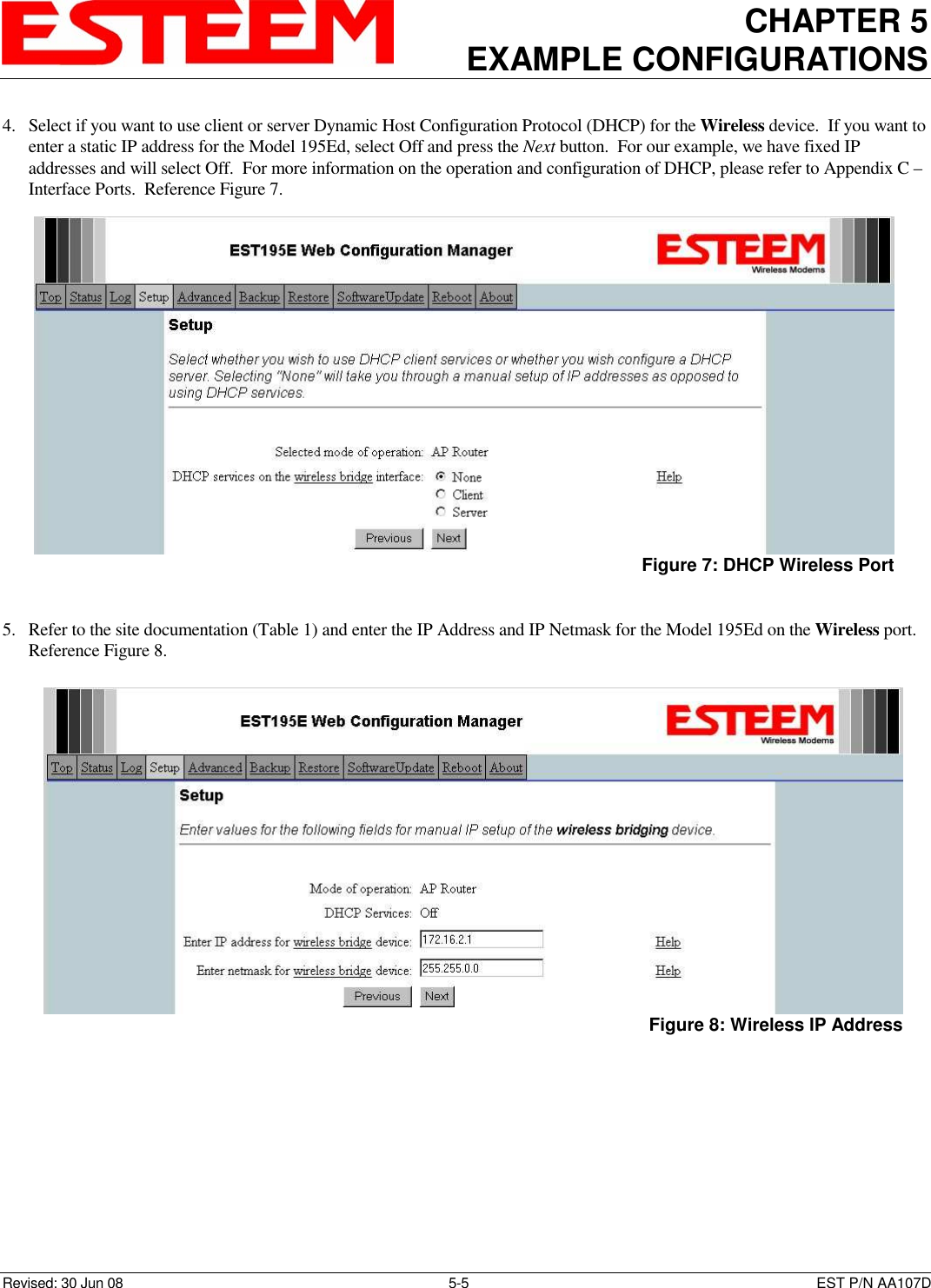
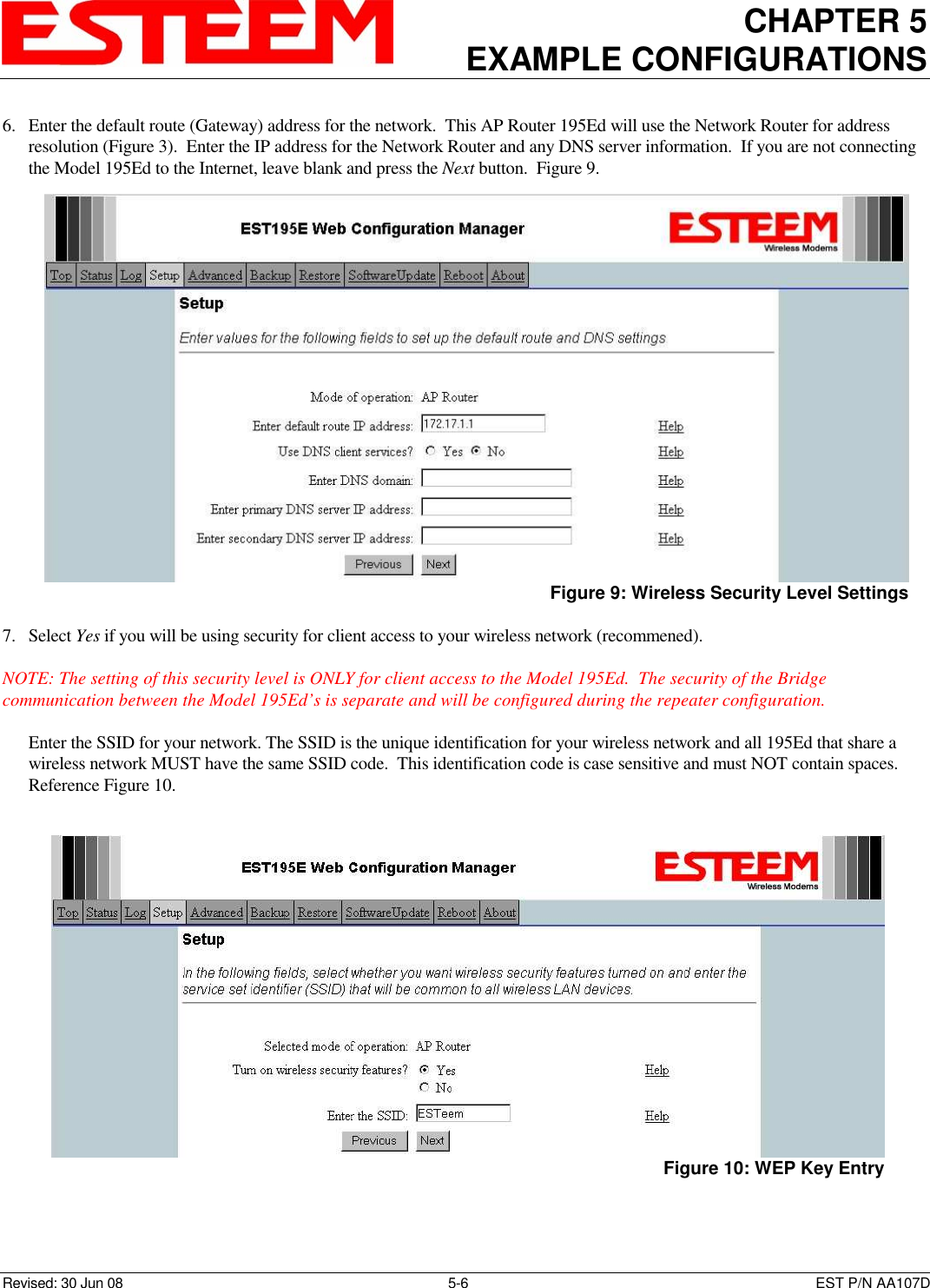
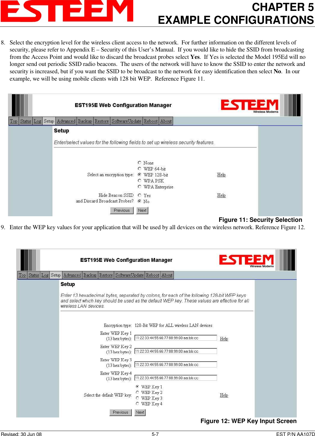
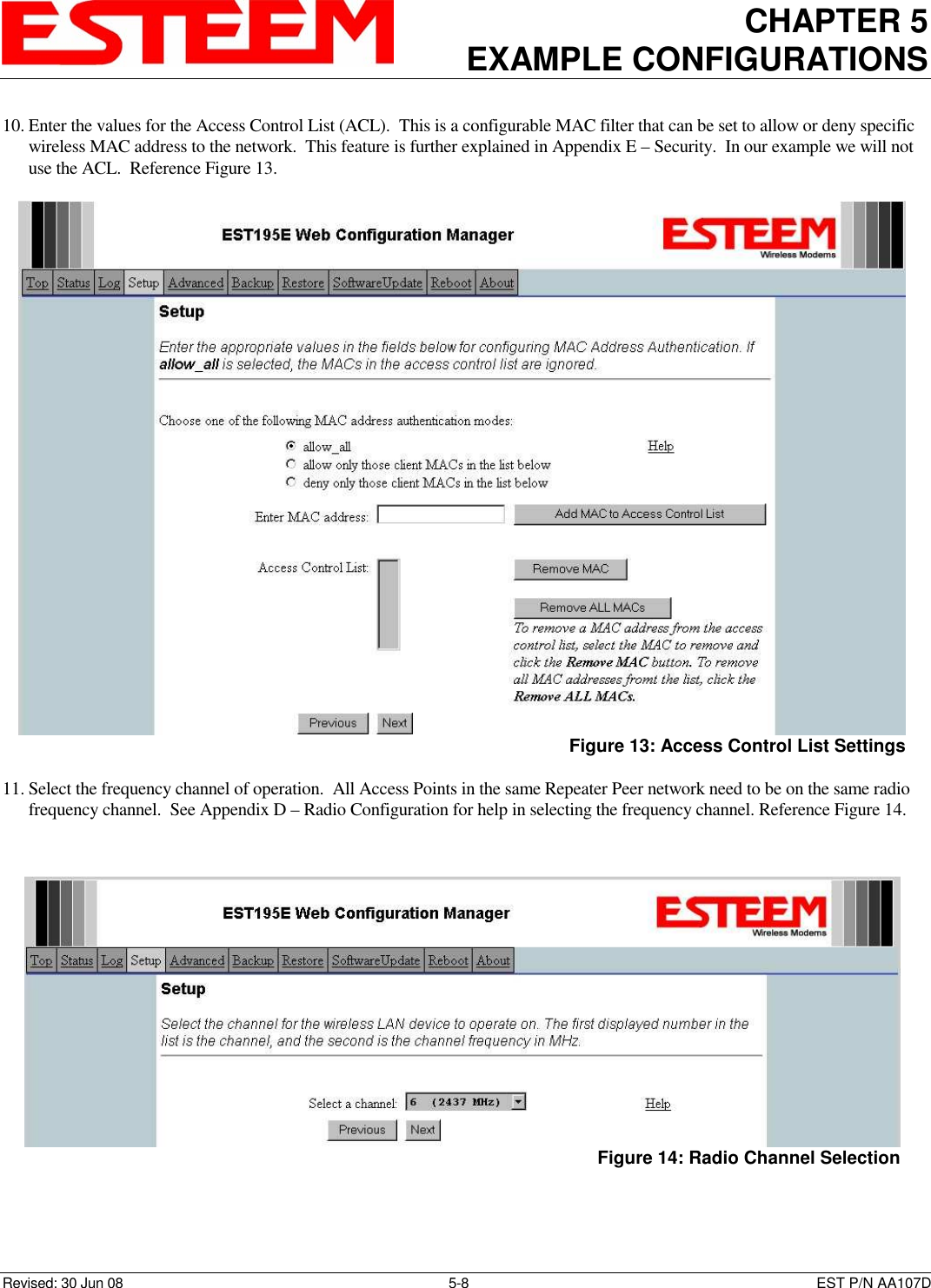
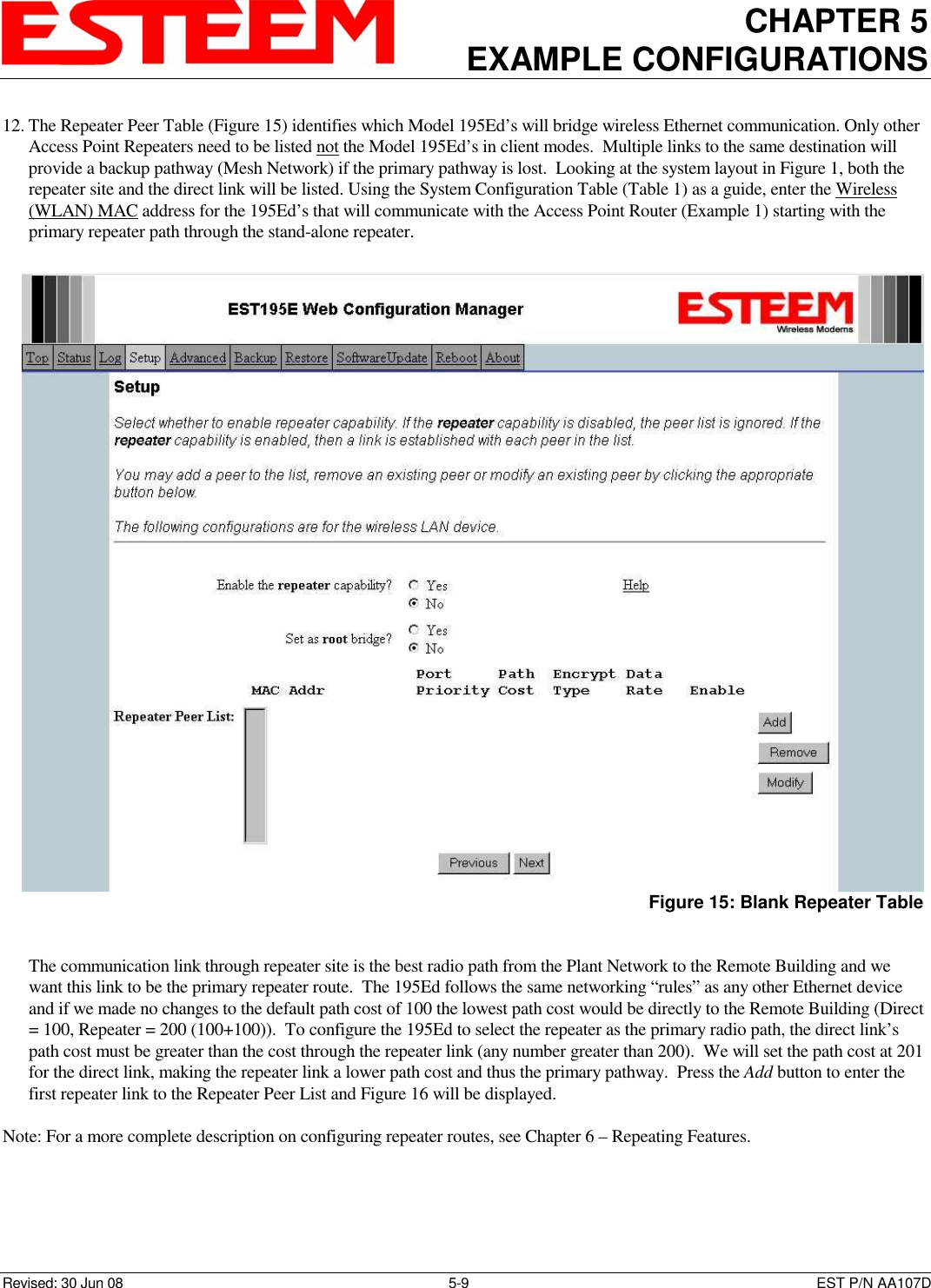
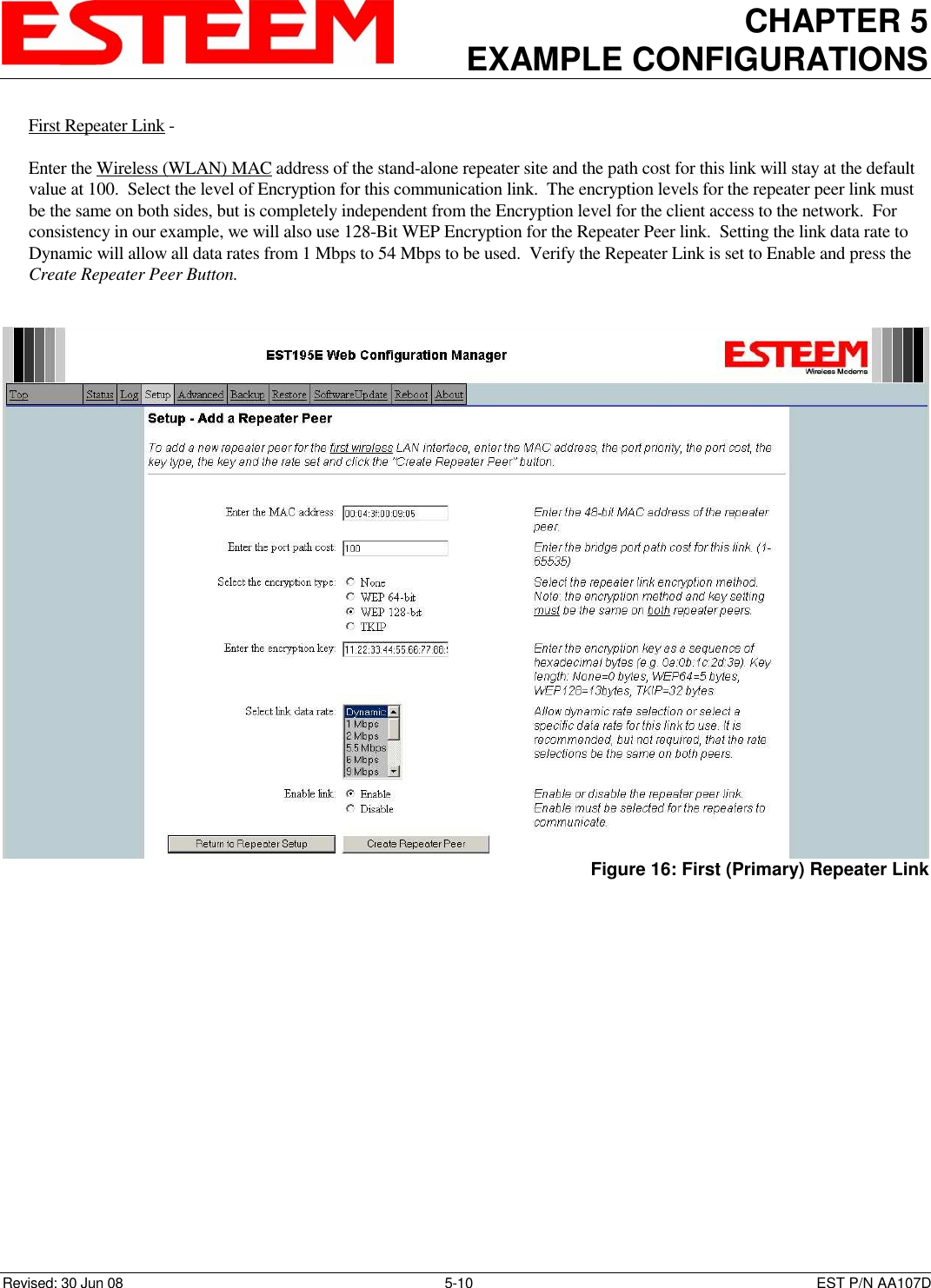
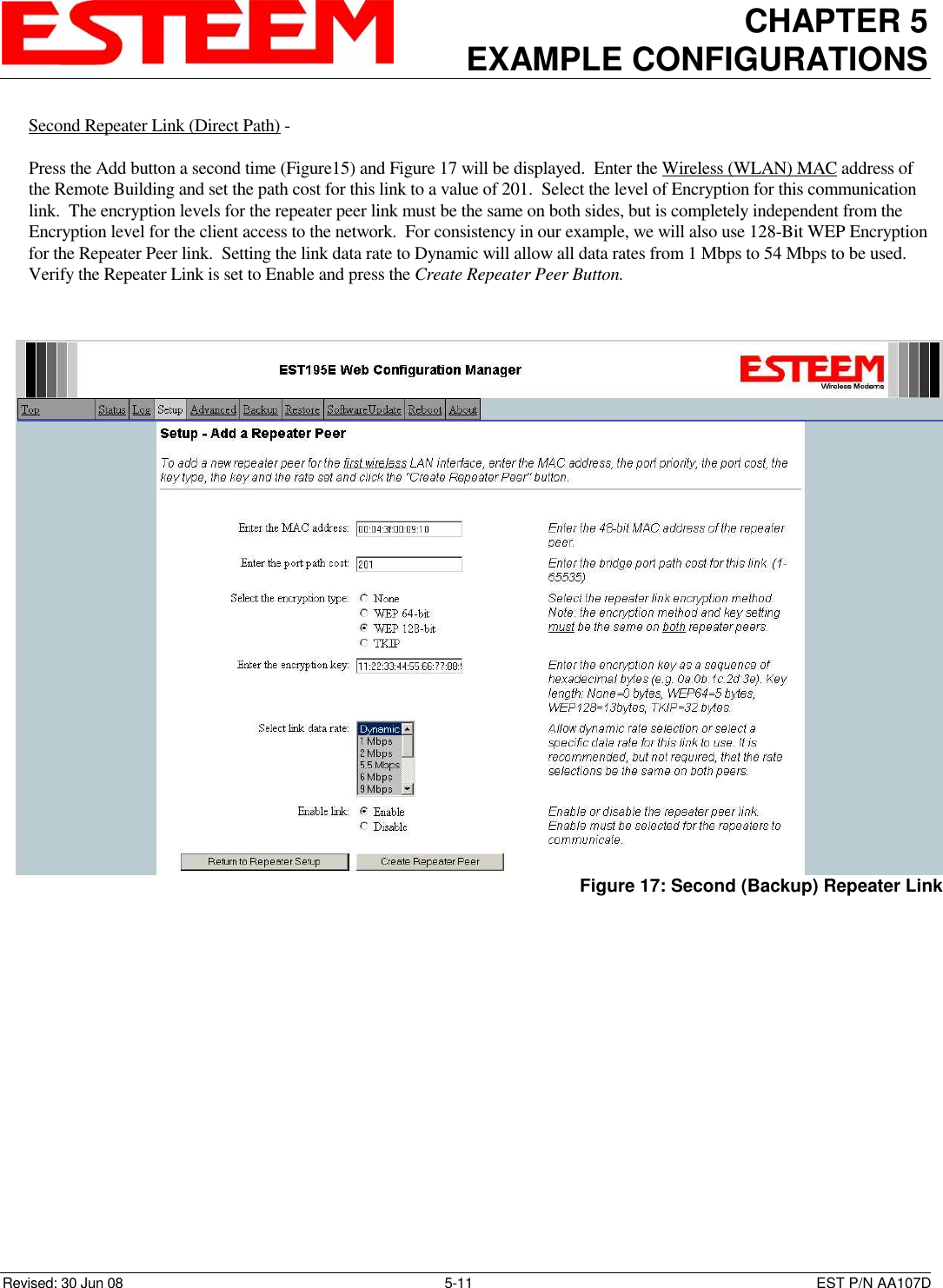
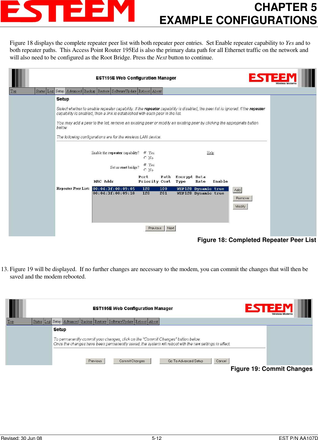
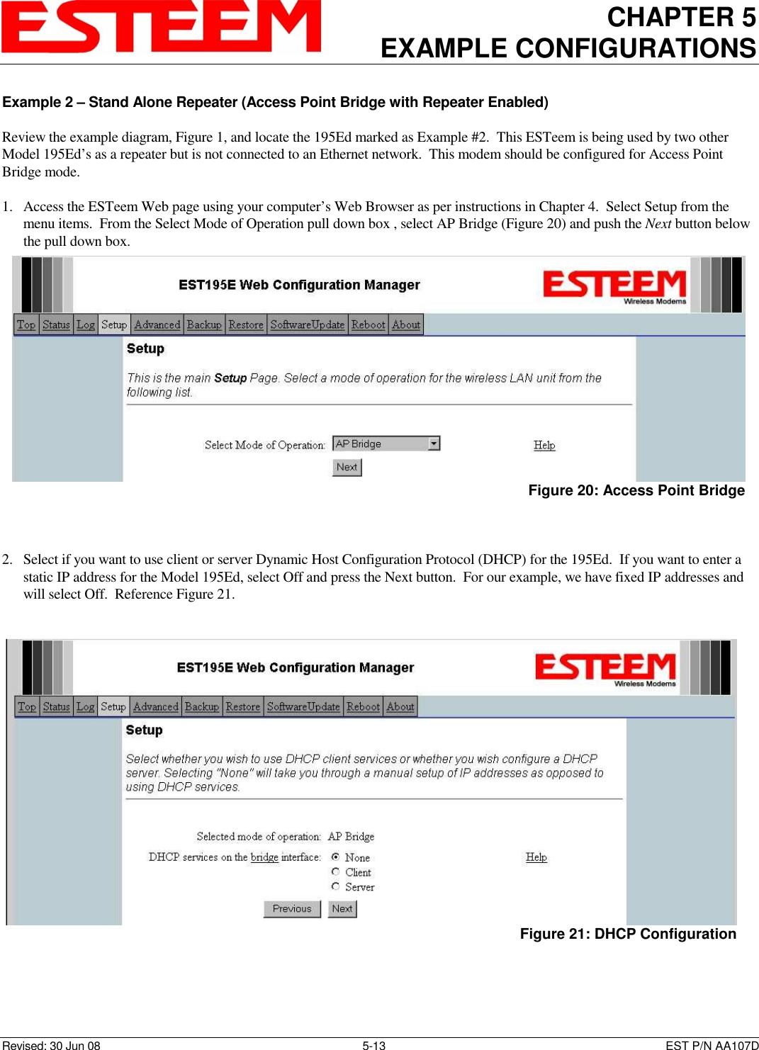
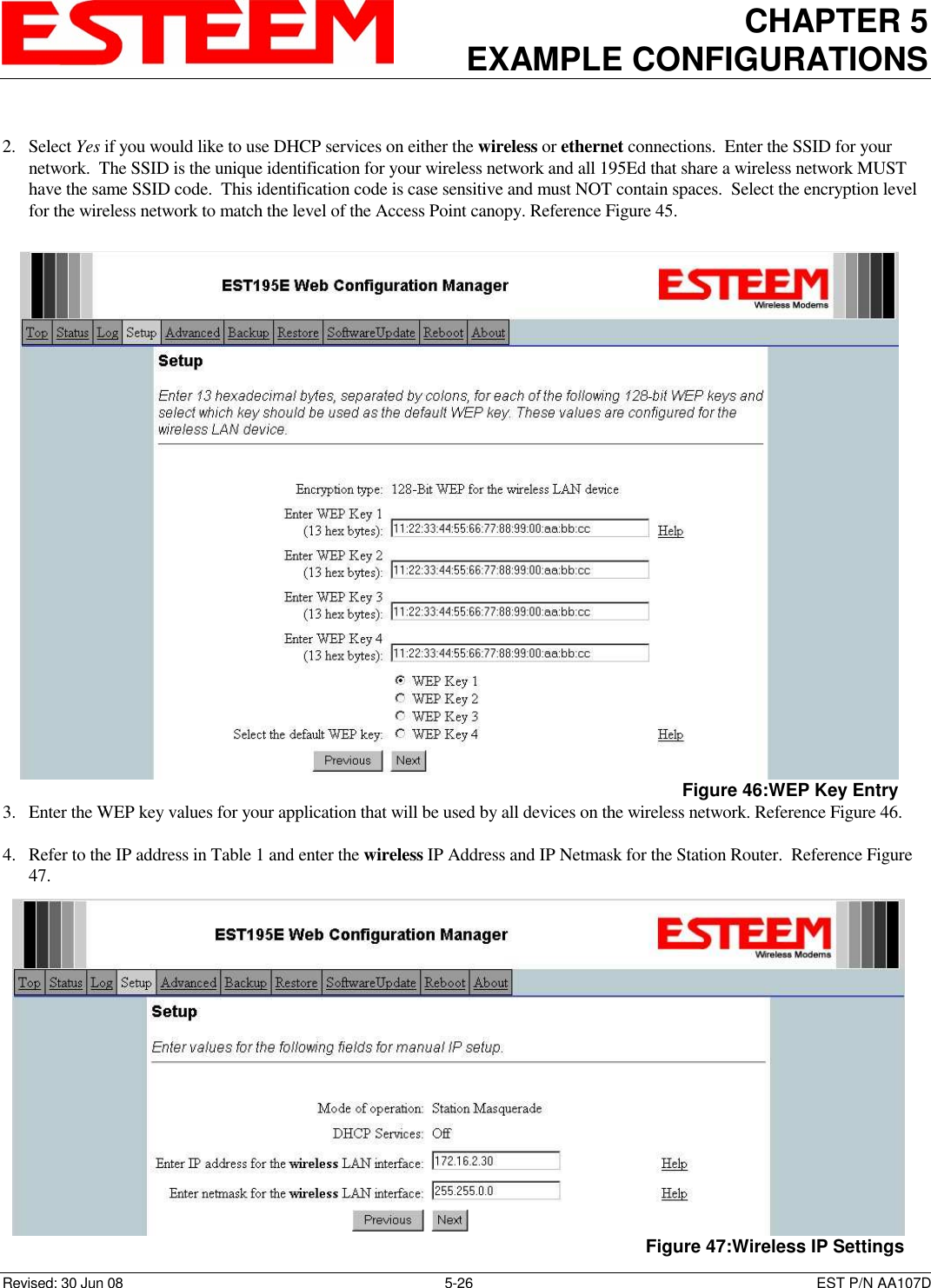
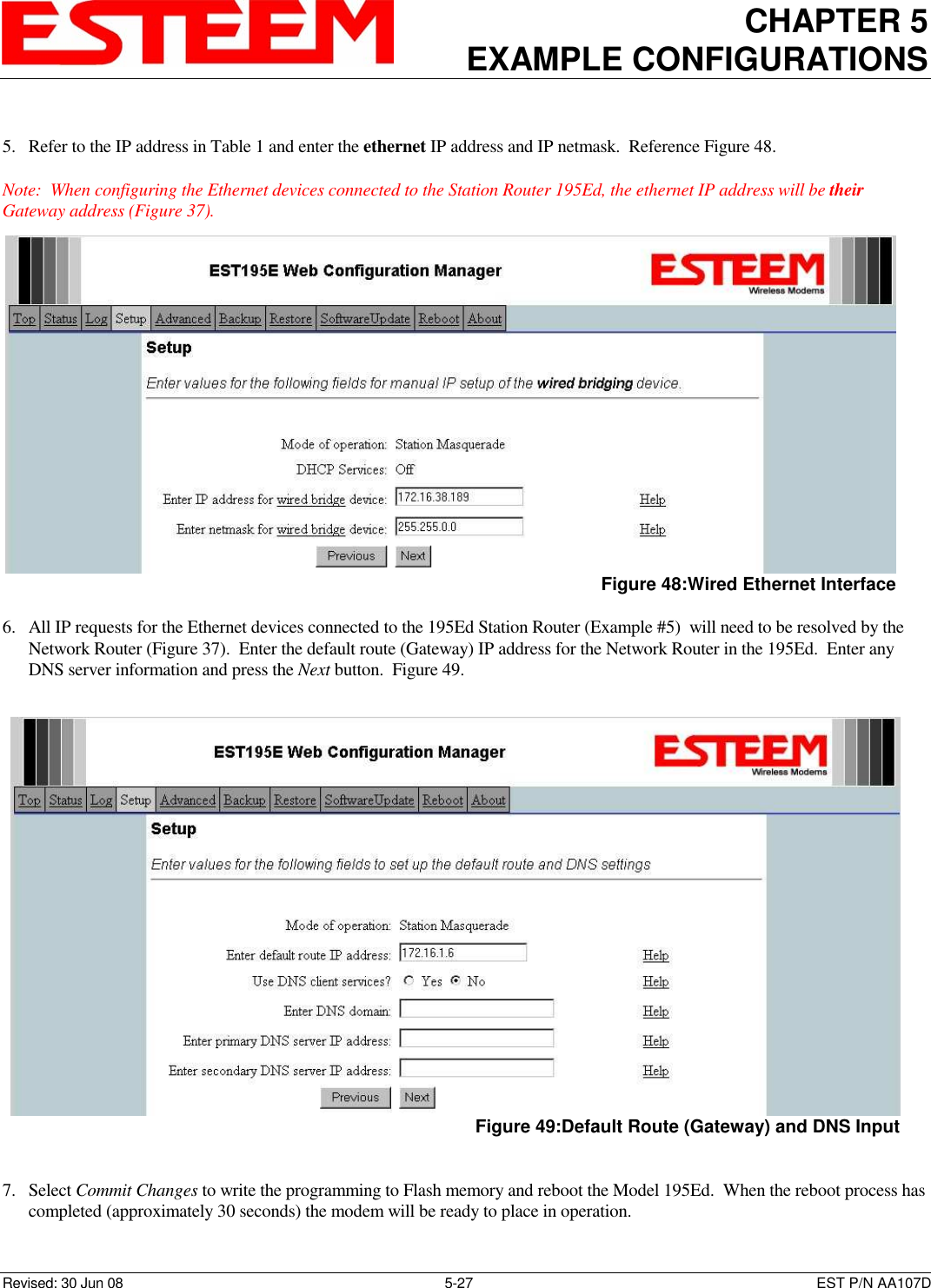
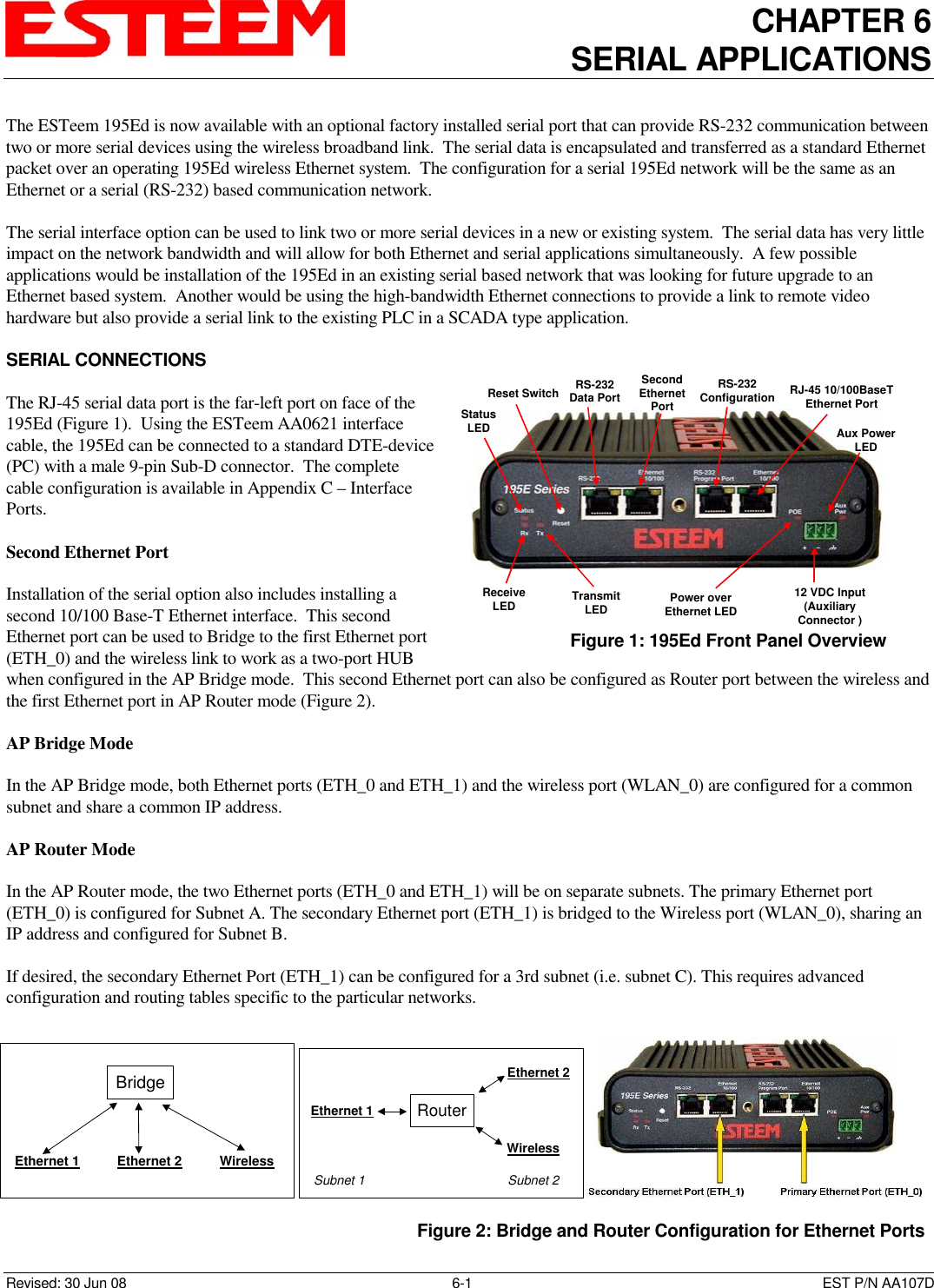
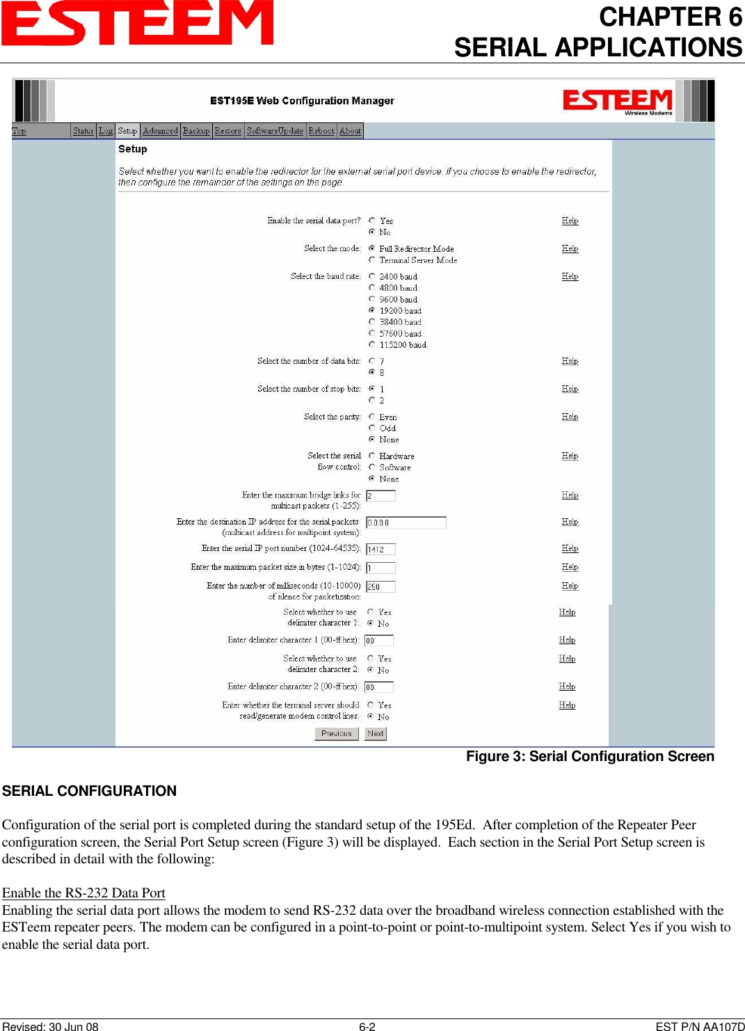
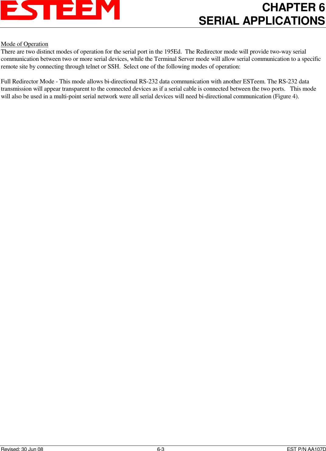
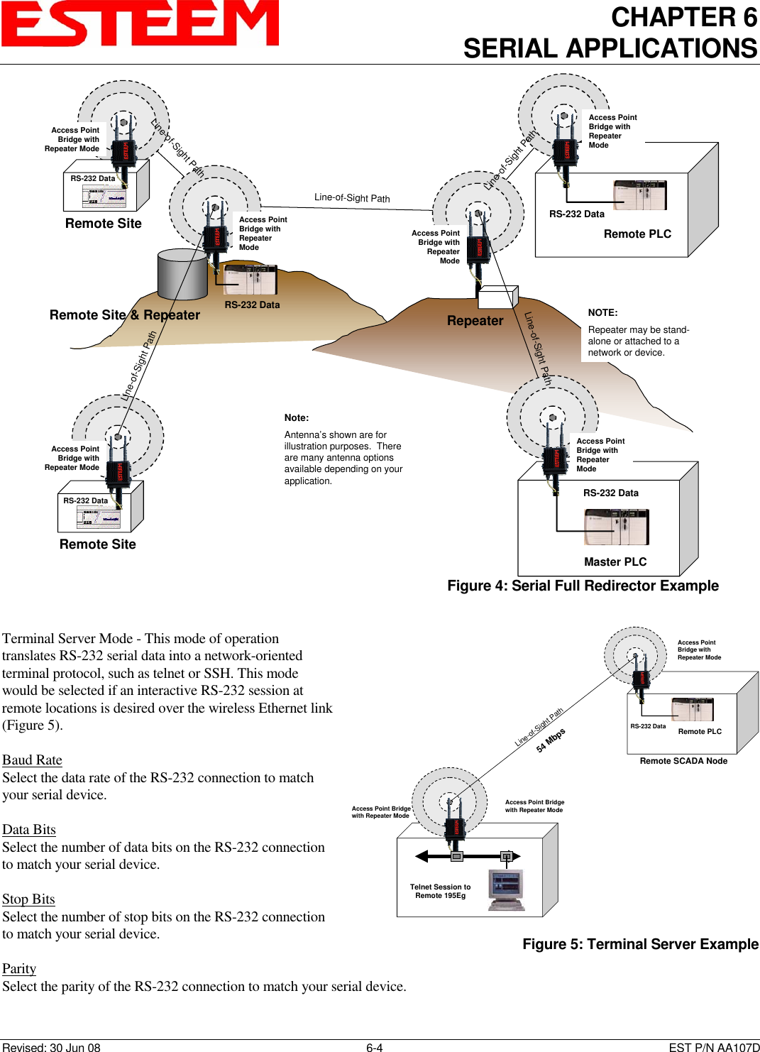
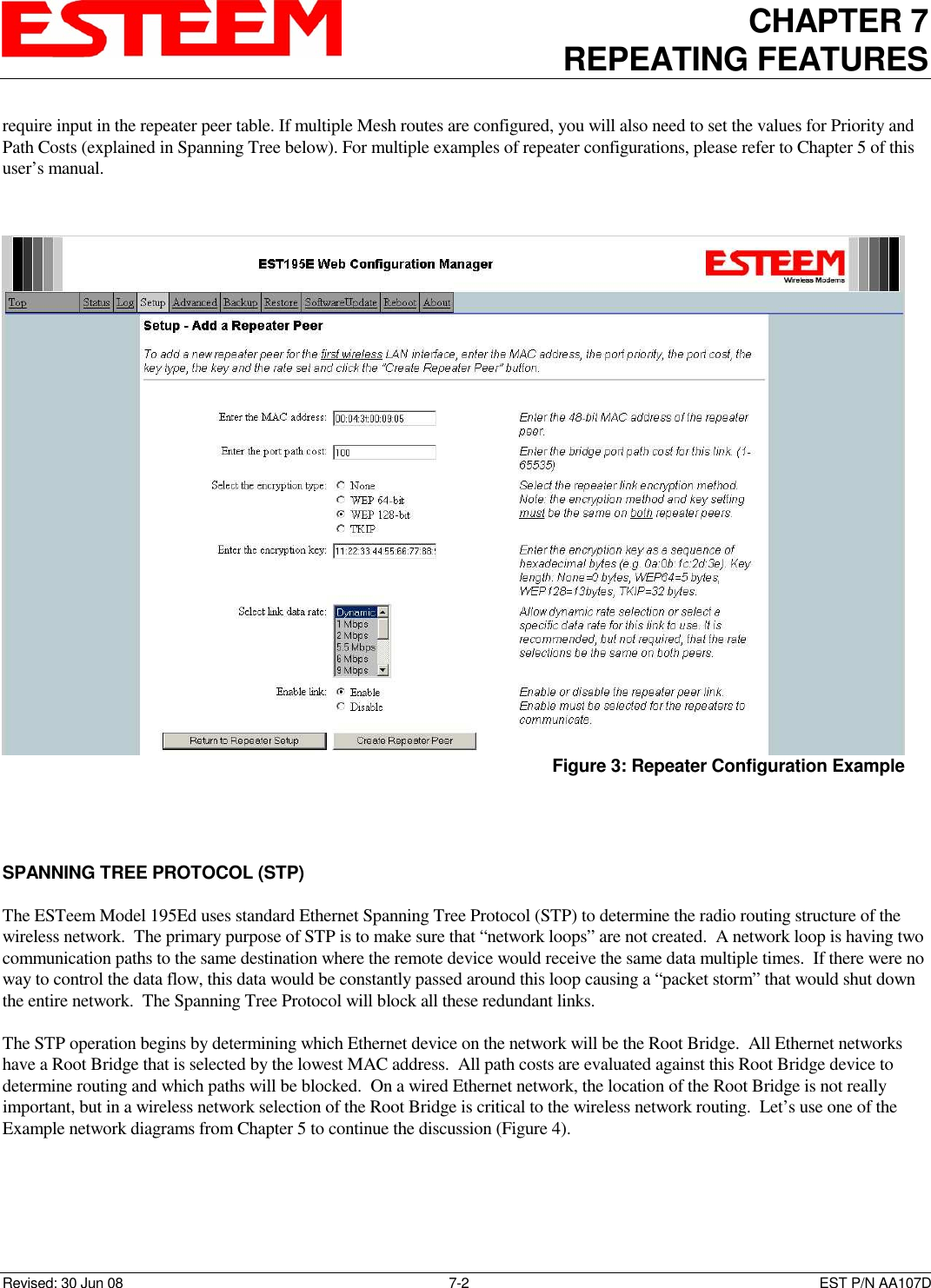
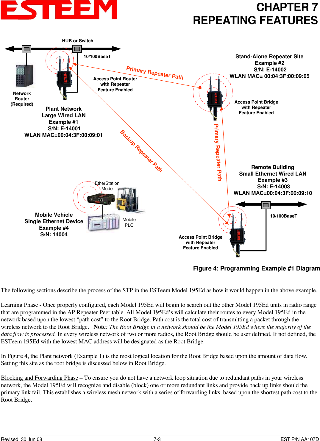
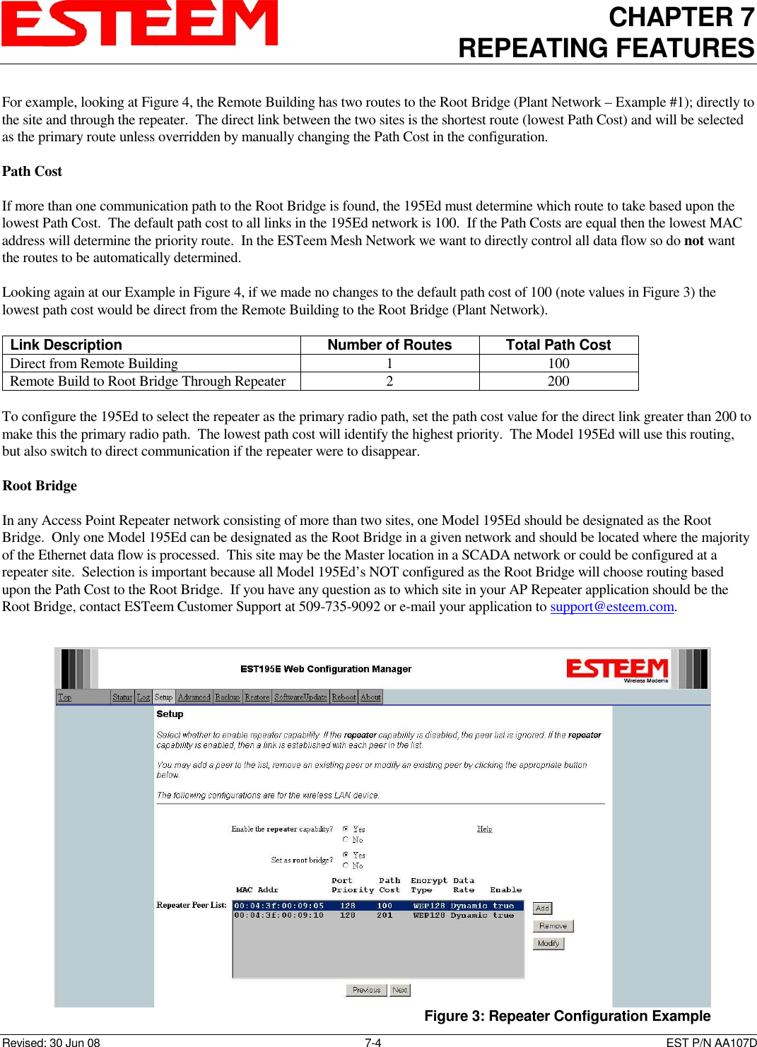
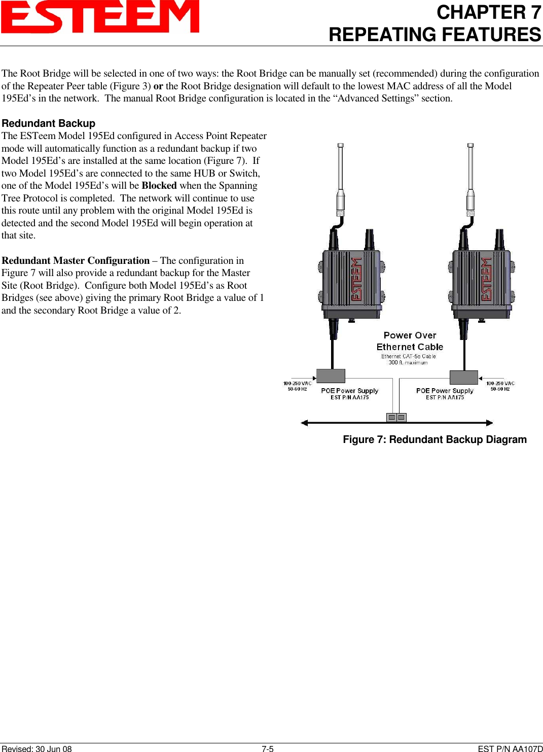
Manual Part 2