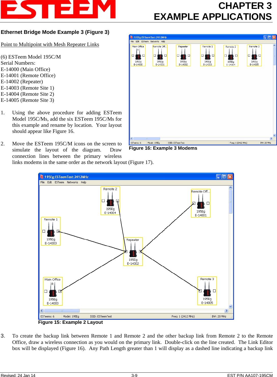
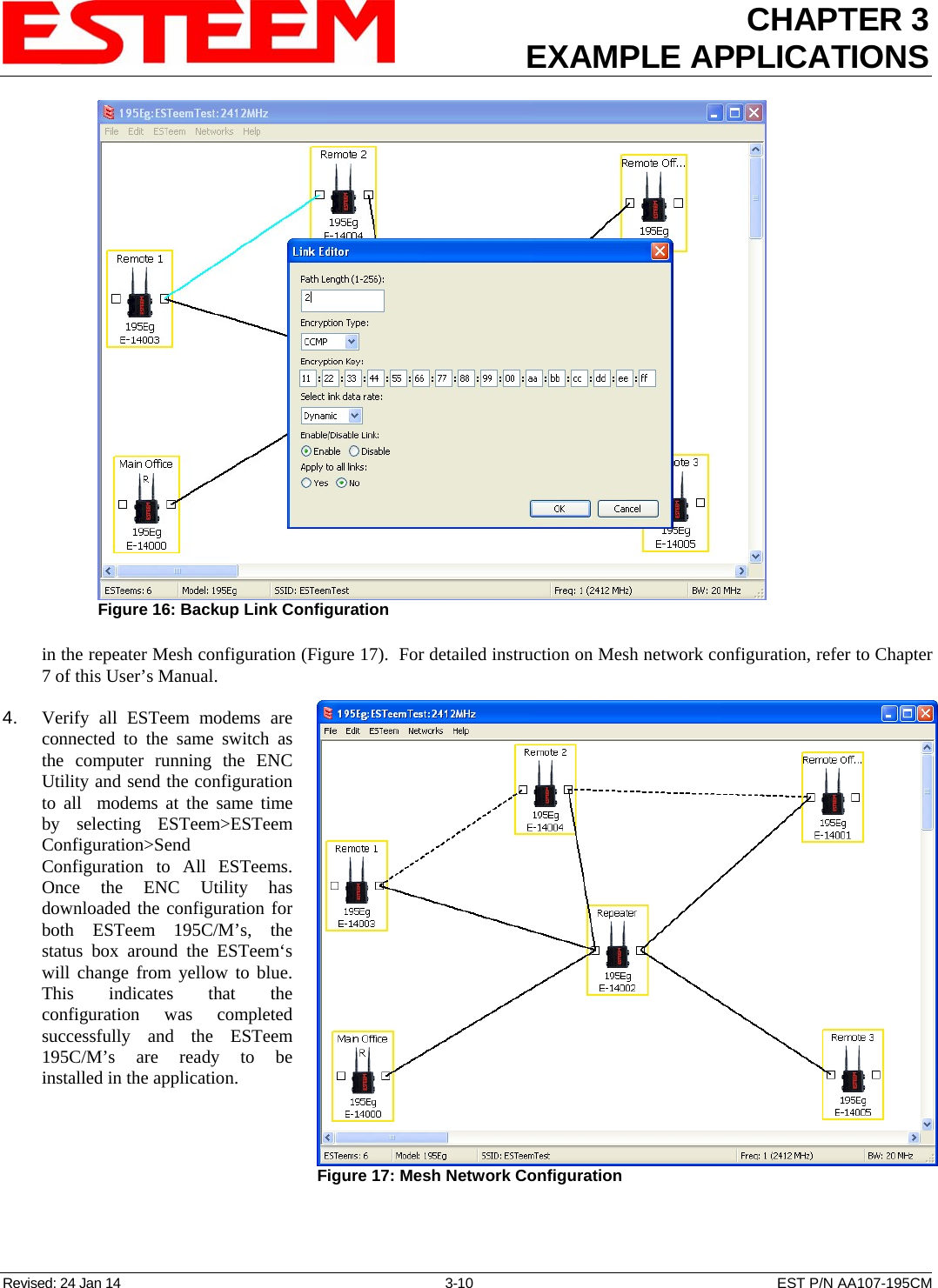
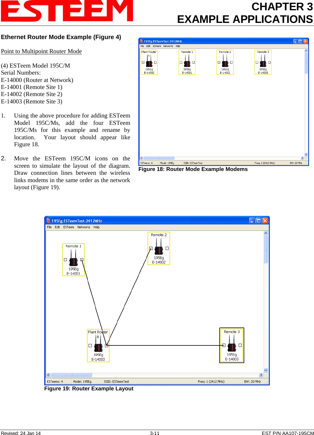
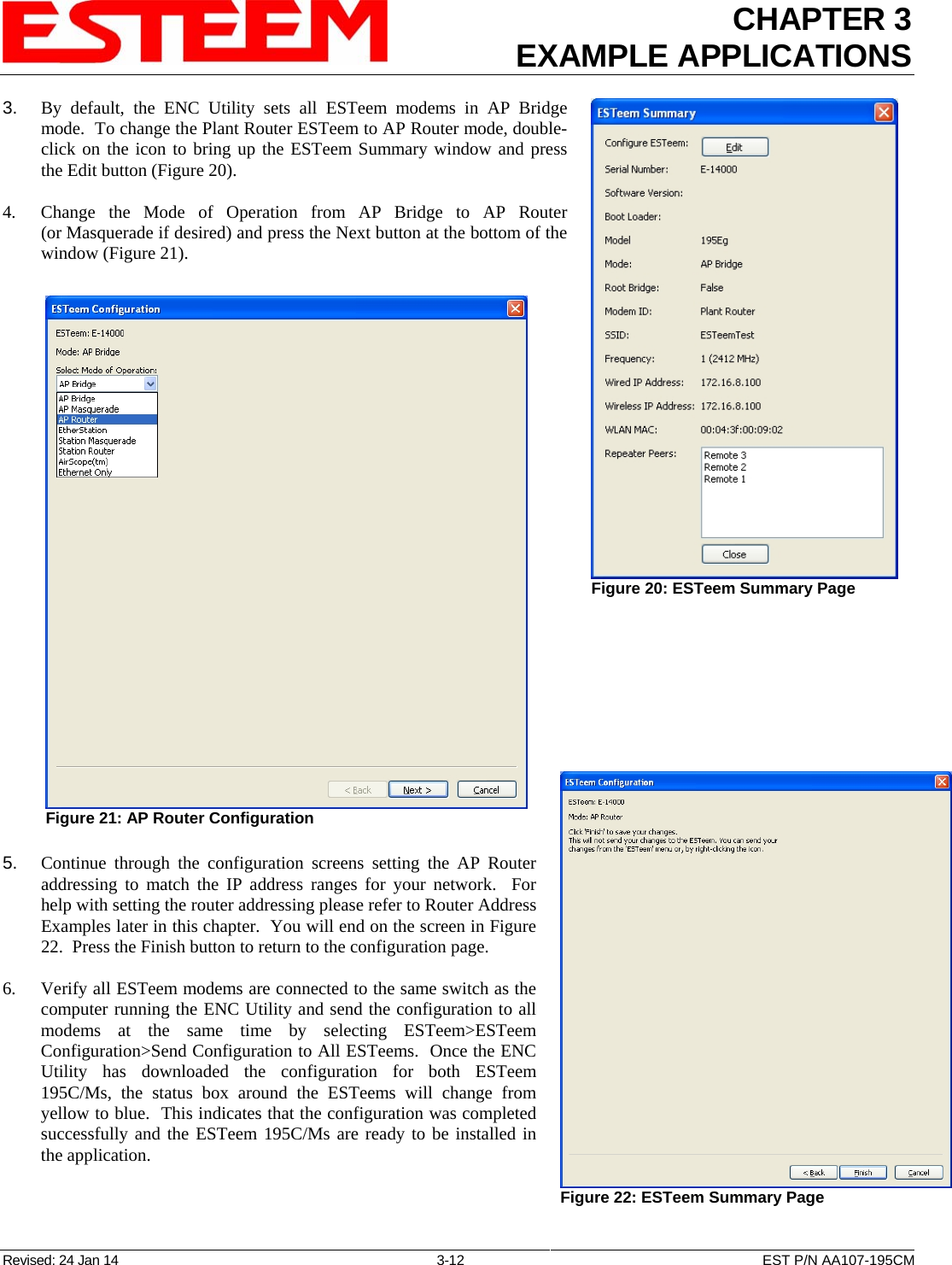
Electronic Systems Technology ESTEEM195M Narrow-band UHF modem User Manual
Electronic Systems Technology Narrow-band UHF modem
UserManual.wiki
>
Electronic Systems Technology
>
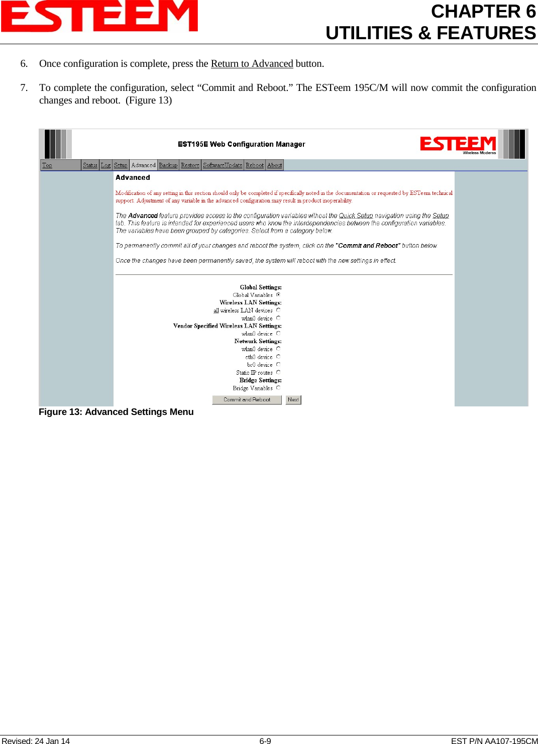
ESTEEM195M User Manual
User Manual
Navigation menu
Upload a User Manual
Namespaces
Wiki Guide
HTML
PDF
Info
Views
User Manual
Discussion / Help
Navigation

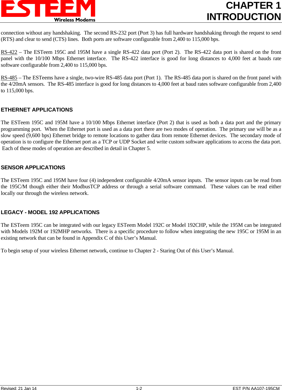

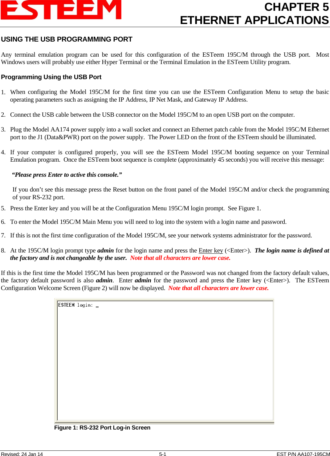
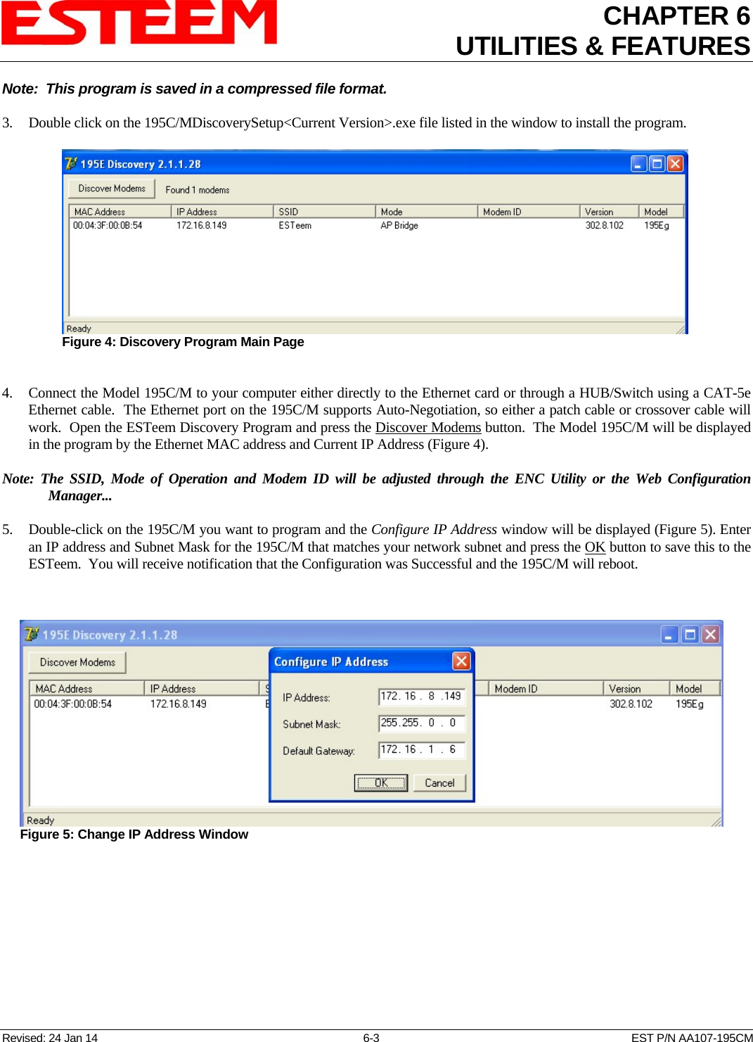
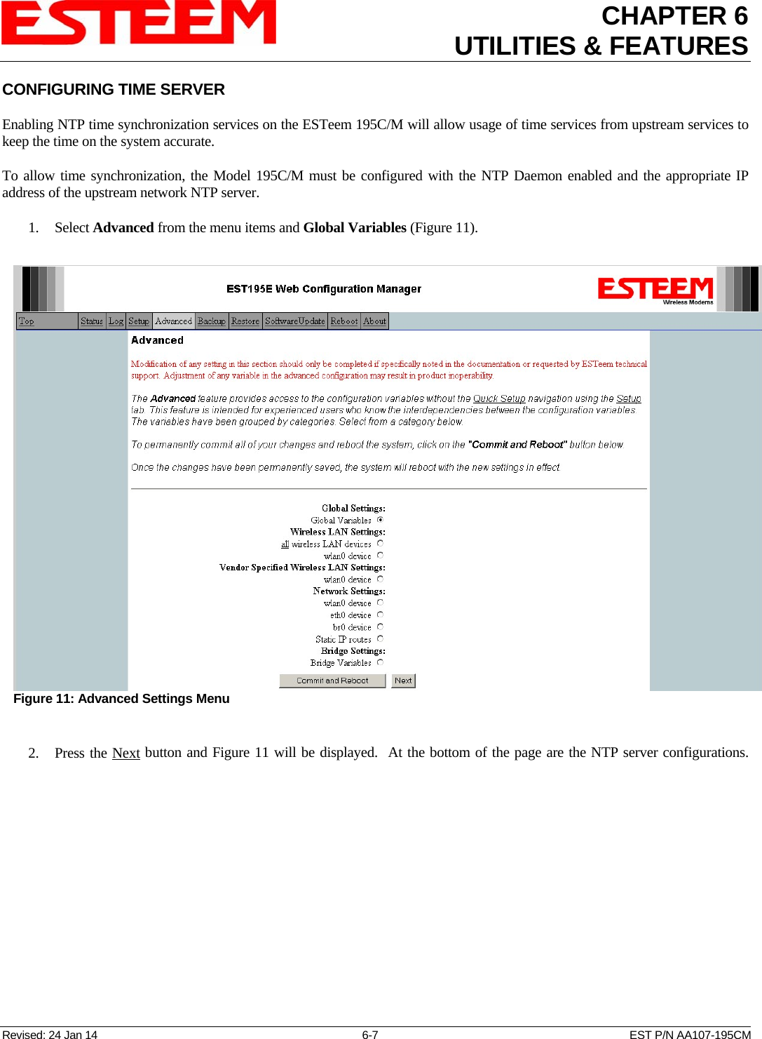
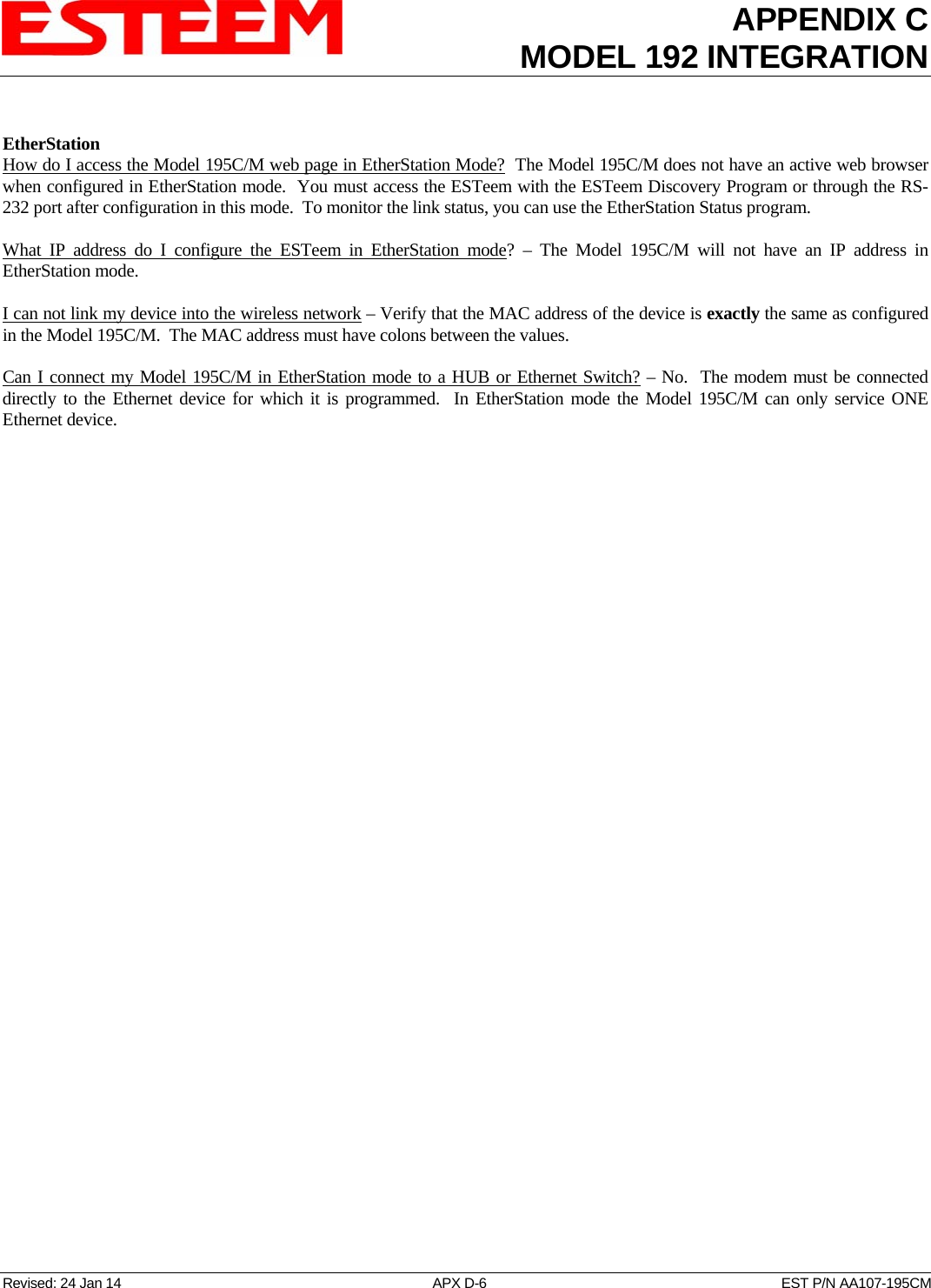
![CHAPTER 6UTILITIES & FEATURES Revised: 24 Jan 14 6-10 EST P/N AA107-195CM Simple Network Management Protocol (SNMP) The ESTeem 195C/M supports SNMP Version 1 (SNMPv1) and Version 2 (SNMPv2c) protocol. This protocol enables any SNMP server to view the status of the wireless network while the system is in operation. The following are a list of the Management Information Base (MIB) items that are supported in the ESTeem 195C/M and their MIB location: MIB Name MIB Directory Location Notes System Temperature EST-MIB::sysInternalTemp.0 in C * 1000 Uptime HOST-RESOURCES-MIB::hrSystemUptime.0 System Update ModemID EST-MIB::sysIdentifier.0 User-specified “nickname” for ESTeem Serial Number EST-MIB::sysSerialNumber.0 ESTeem serial number Model EST-MIB::sysModel.0 ESTeem model number Firmware Version EST-MIB::sysFirmwareRevision.0 Firmware revision System Mode EST-MIB::sysMode.0 AP_BRIDGE/STA_ETHERSTA, etc Free Memory UCD-SNMP-MIB::memTotalFree.0 Total Free Memory Idle CPU UCD-SNMP-MIB::ssCpuIdle.0 Percentage of CPU Idle [[ per-interface ]] IP Address IF-MIB::ifAddress Port Speed IF-MIB::ifSpeed In bps Port Status IF-MIB::ifOperStatus Mac Address IF-MIB::ifPhysAddress [[ per-wlandev entry ]] EST-MIB::wirelessDevicesNumber.0 Wireless Port Identification Device Name EST-MIB::wirelessDeviceTable.1.wName.1 Name of device (wlan0 standard) MAC Address EST-MIB::wirelessDeviceTable.1.wMacAddress.1 MAC address of WLAN port Mode EST-MIB::wirelessDeviceTable.1.wMode.1 Current Mode ap=access point, sta=station mode and airscope Frequency EST-MIB::wirelessDeviceTable.1.wFreq.1 Frequency in MHz Bandwidth EST-MIB::wirelessDeviceTable.1.wBandwidth.1 Bandwidth (5, 10, or 20 MHz if used) SSID EST-MIB::wirelessDeviceTable.1.wSSID.1 Service Set Identification BSSID EST-MIB::wirelessDeviceTable.1.wBSSID.1 Basic Service Set Identification Operational Rates EST-MIB::wirelessDeviceTable.1.wOpRates.1 List of RF Data Rates in Rate Set Basic Rates EST-MIB::wirelessDeviceTable.1.wBasRates.1 List of RF Basic Rates for status messages](https://usermanual.wiki/Electronic-Systems-Technology/ESTEEM195M/User-Guide-2186893-Page-48.png)
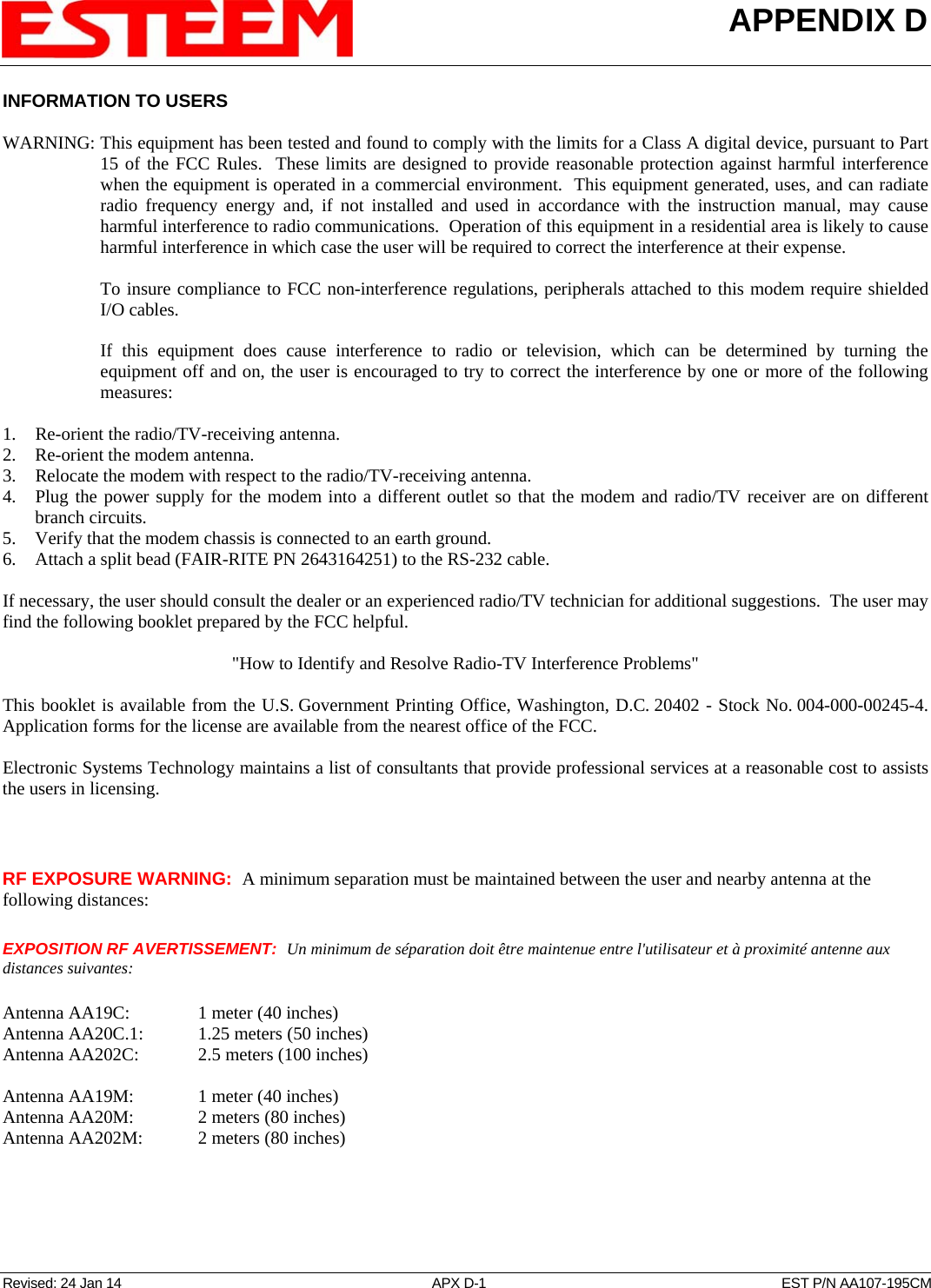
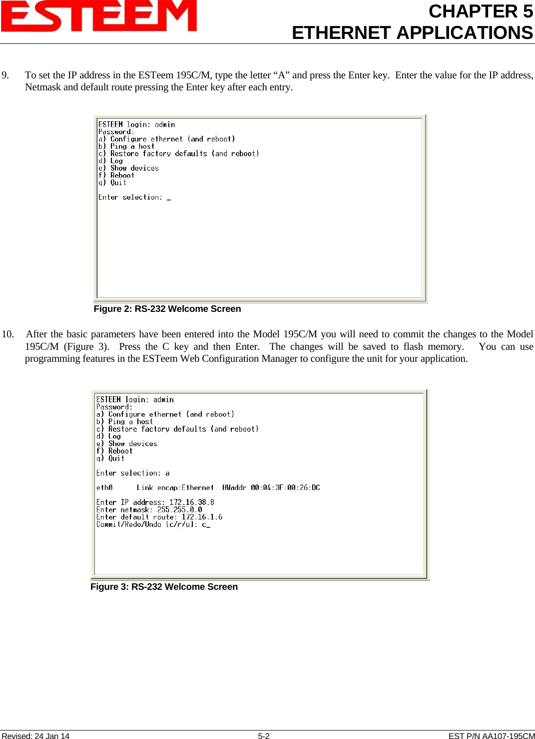
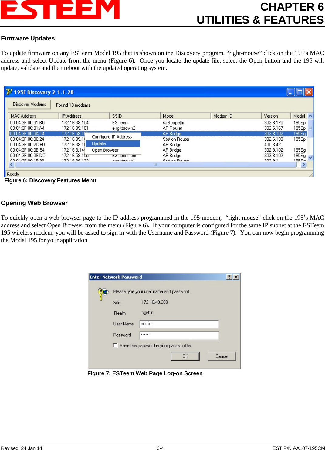
![CHAPTER 6UTILITIES & FEATURES [[ peer table entry ]] All entries in the Peer Table will have a device entry index, both ESTeem and other wireless devices EST-MIB::wirelessPeersNumber.0 Total number of peer entries in table wlan device EST-MIB::wirelessPeerTable.1.pDevice.1 index into the wirelessDeviceTable (each entry will have a unique number Peer MAC Address EST-MIB::wirelessPeerTable.1.pMacAddr.1 MAC address of peer isRepeater? EST-MIB::wirelessPeerTable.1.pRepeater.1 Is the peer an ESTeem repeater isAP? EST-MIB::wirelessPeerTable.1.pAP.1 Is the peer an Access Point isAssocSta? EST-MIB::wirelessPeerTable.1.pAssoc.1 Is the peer an Mobile Client isAdhoc? EST-MIB::wirelessPeerTable.1.pAdhoc.1 Is the peer an AdHoc Station (802.11 only) Frequency EST-MIB::wirelessPeerTable.1.pFreq.1 Frequency in MHz current rate set EST-MIB::wirelessPeerTable.1.pCurRates.1 Current Operating Rates last rx signal EST-MIB::wirelessPeerTable.1.pSignal.1 Receive Signal in –dBm last rx noise EST-MIB::wirelessPeerTable.1.pNoise.1 Background Noise in –dBm BSSID EST-MIB::wirelessPeerTable.1.pBssid.1 Basic Service Set ID (In Hex) SSID EST-MIB::wirelessPeerTable.1.pSSID.1 SSID in Text isValid? EST-MIB::wirelessPeerTable.1.pCurrent.1 True if peer info is for a “current” peer. last rx EST-MIB::wirelessPeerTable.1.pLastRxl.1 seconds since last received packet from peer last tx EST-MIB::wirelessPeerTable.1.pLastTx.1 seconds since last transmitted packet to peer current tx rate EST-MIB::wirelessPeerTable.1.pCurrentRate.1 current tx rate in bps. Downloading MIB Tables To download the MIB items listed above and import into your SNMP server, log into any ESTeem 195C/M and select the About page (Figure 20). Press the Download MIB Files hyperlink on the page and save the files to your computer. Figure 14: MIB Table Download Revised: 24 Jan 14 6-11 EST P/N AA107-195CM](https://usermanual.wiki/Electronic-Systems-Technology/ESTEEM195M/User-Guide-2186893-Page-49.png)