Electronic Systems Technology ESTEEM210M Data radio modem User Manual ESTEEM USERS MANUAL
Electronic Systems Technology Data radio modem ESTEEM USERS MANUAL
UserManual.wiki
>
Electronic Systems Technology
>
ESTEEM210M User Manual
User Manual
Navigation menu
Upload a User Manual
Namespaces
Wiki Guide
HTML
PDF
Info
Views
User Manual
Discussion / Help
Navigation

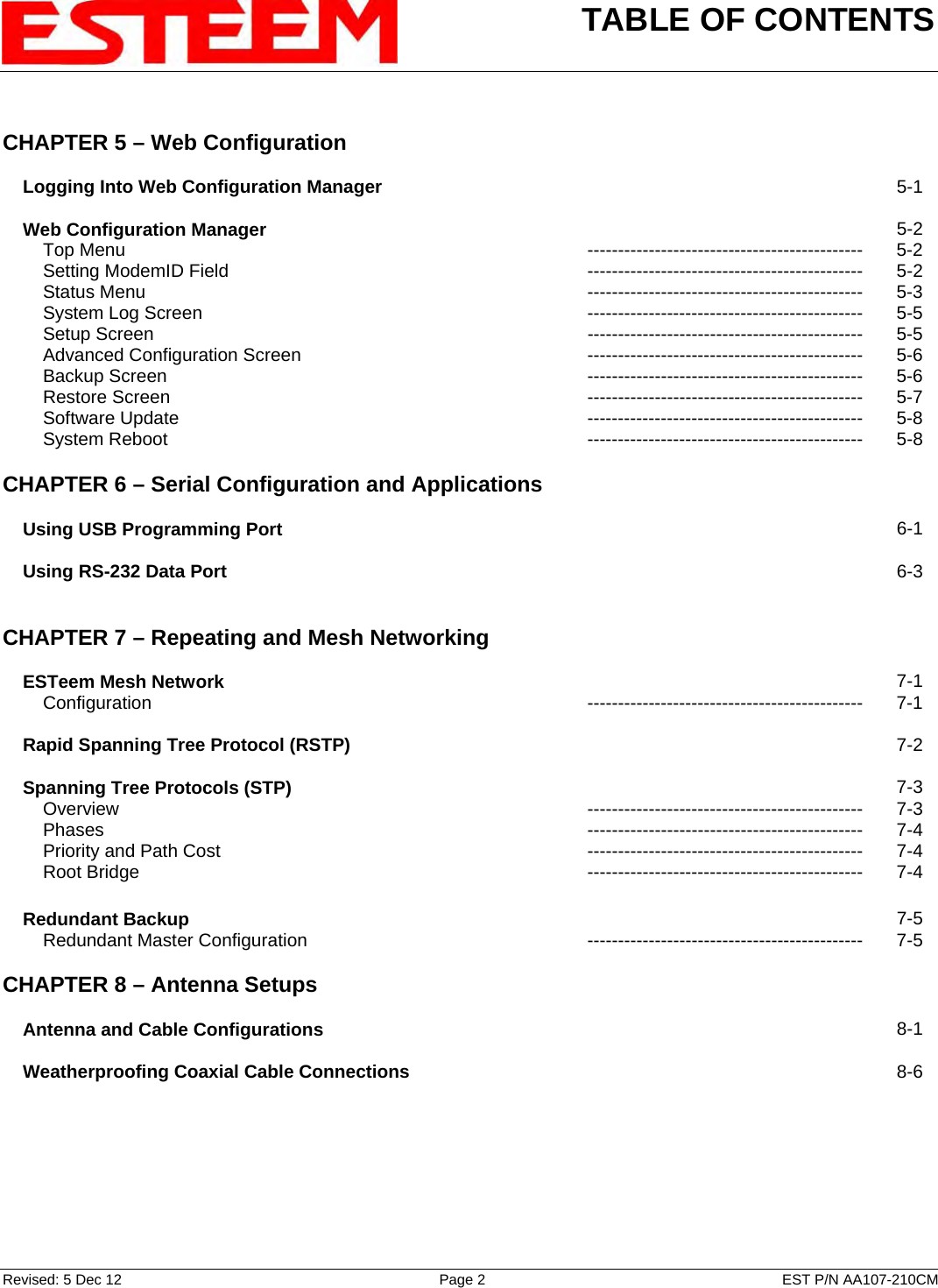
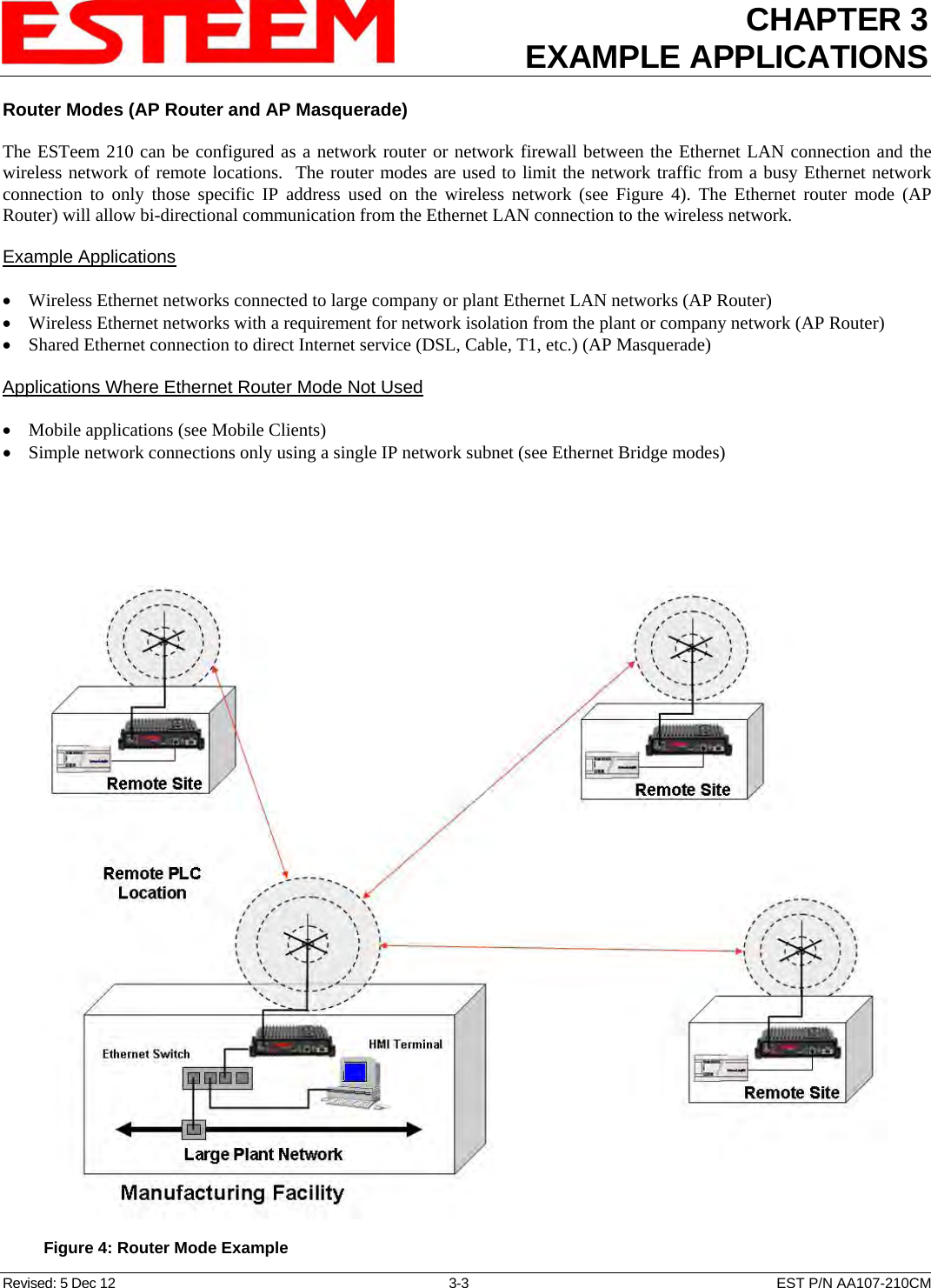
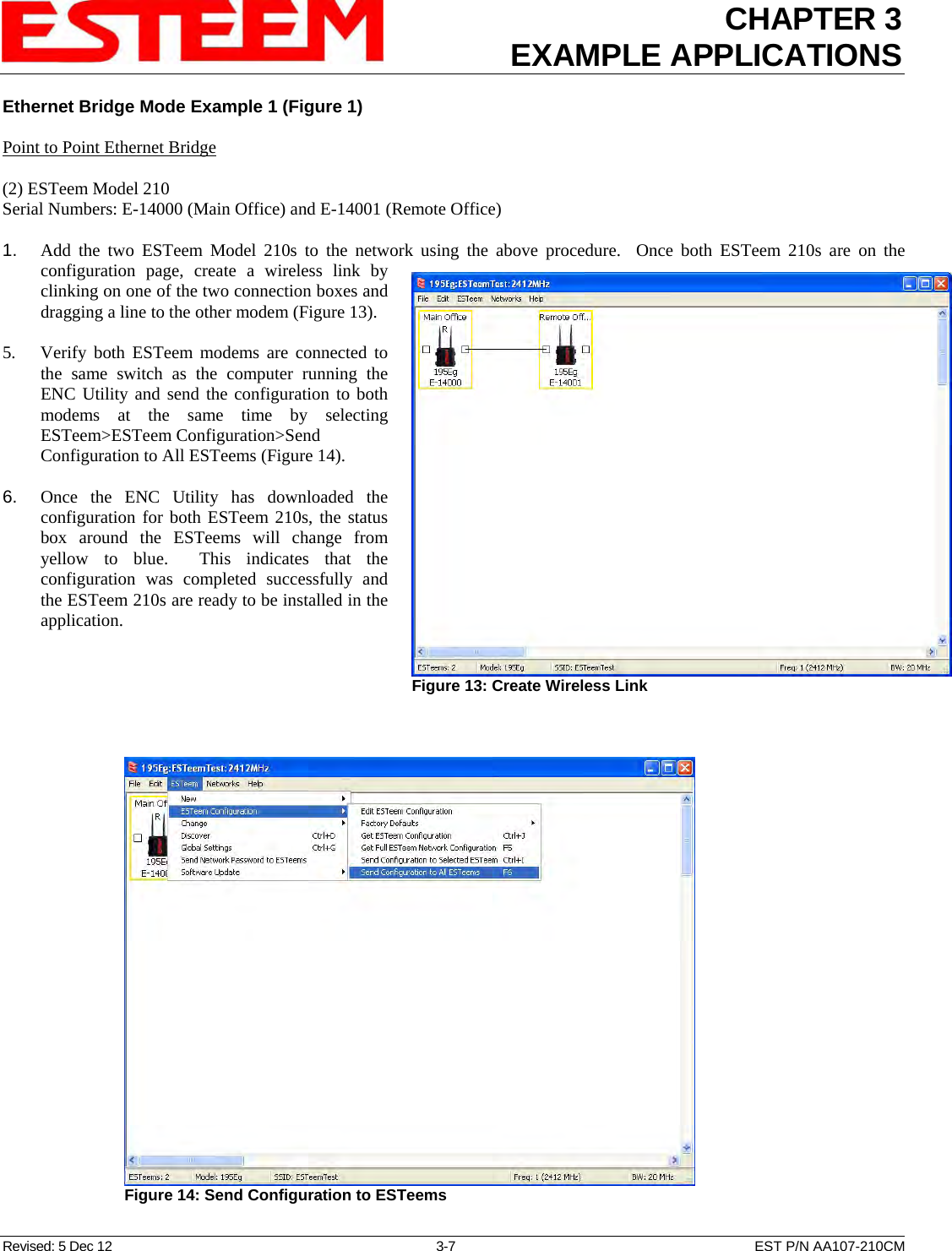
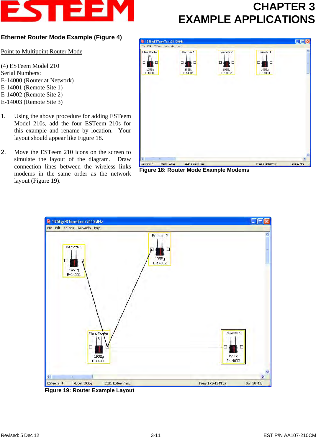

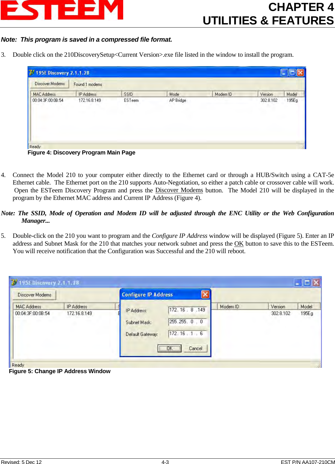
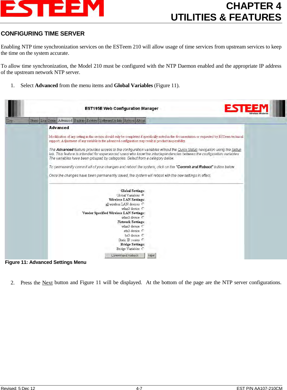
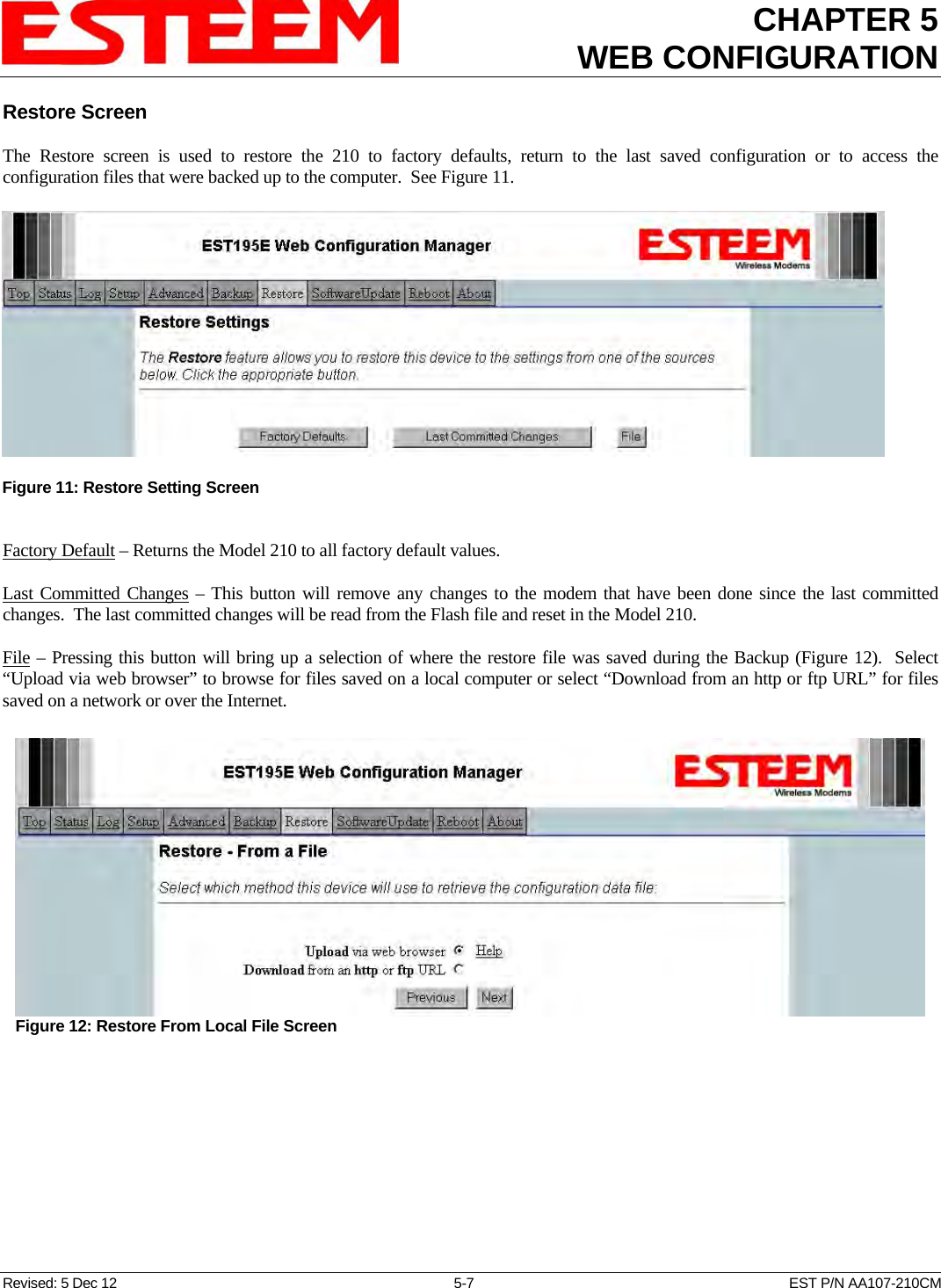
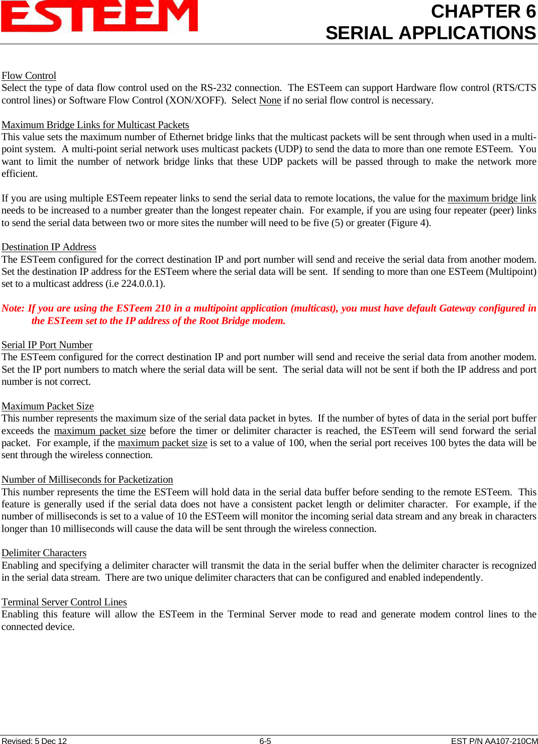
![CHAPTER 4UTILITIES & FEATURES Revised: 5 Dec 12 4-10 EST P/N AA107-210CM Simple Network Management Protocol (SNMP) The ESTeem 210 supports SNMP Version 1 (SNMPv1) and Version 2 (SNMPv2c) protocol. This protocol enables any SNMP server to view the status of the wireless network while the system is in operation. The following are a list of the Management Information Base (MIB) items that are supported in the ESTeem 210 and their MIB location: MIB Name MIB Directory Location Notes System Temperature EST-MIB::sysInternalTemp.0 in C * 1000 Uptime HOST-RESOURCES-MIB::hrSystemUptime.0 System Update ModemID EST-MIB::sysIdentifier.0 User-specified “nickname” for ESTeem Serial Number EST-MIB::sysSerialNumber.0 ESTeem serial number Model EST-MIB::sysModel.0 ESTeem model number Firmware Version EST-MIB::sysFirmwareRevision.0 Firmware revision System Mode EST-MIB::sysMode.0 AP_BRIDGE/STA_ETHERSTA, etc Free Memory UCD-SNMP-MIB::memTotalFree.0 Total Free Memory Idle CPU UCD-SNMP-MIB::ssCpuIdle.0 Percentage of CPU Idle [[ per-interface ]] IP Address IF-MIB::ifAddress Port Speed IF-MIB::ifSpeed In bps Port Status IF-MIB::ifOperStatus Mac Address IF-MIB::ifPhysAddress [[ per-wlandev entry ]] EST-MIB::wirelessDevicesNumber.0 Wireless Port Identification Device Name EST-MIB::wirelessDeviceTable.1.wName.1 Name of device (wlan0 standard) MAC Address EST-MIB::wirelessDeviceTable.1.wMacAddress.1 MAC address of WLAN port Mode EST-MIB::wirelessDeviceTable.1.wMode.1 Current Mode ap=access point, sta=station mode and airscope Frequency EST-MIB::wirelessDeviceTable.1.wFreq.1 Frequency in MHz Bandwidth EST-MIB::wirelessDeviceTable.1.wBandwidth.1 Bandwidth (5, 10, or 20 MHz if used) SSID EST-MIB::wirelessDeviceTable.1.wSSID.1 Service Set Identification BSSID EST-MIB::wirelessDeviceTable.1.wBSSID.1 Basic Service Set Identification Operational Rates EST-MIB::wirelessDeviceTable.1.wOpRates.1 List of RF Data Rates in Rate Set Basic Rates EST-MIB::wirelessDeviceTable.1.wBasRates.1 List of RF Basic Rates for status messages](https://usermanual.wiki/Electronic-Systems-Technology/ESTEEM210M/User-Guide-2062976-Page-39.png)
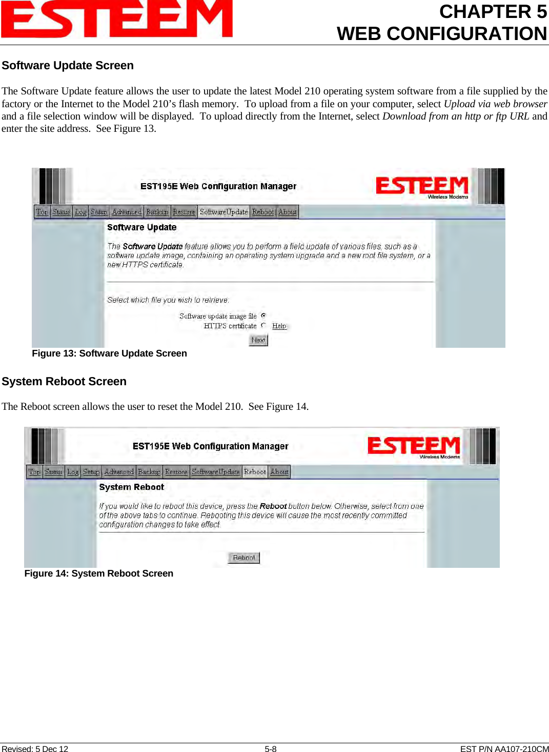
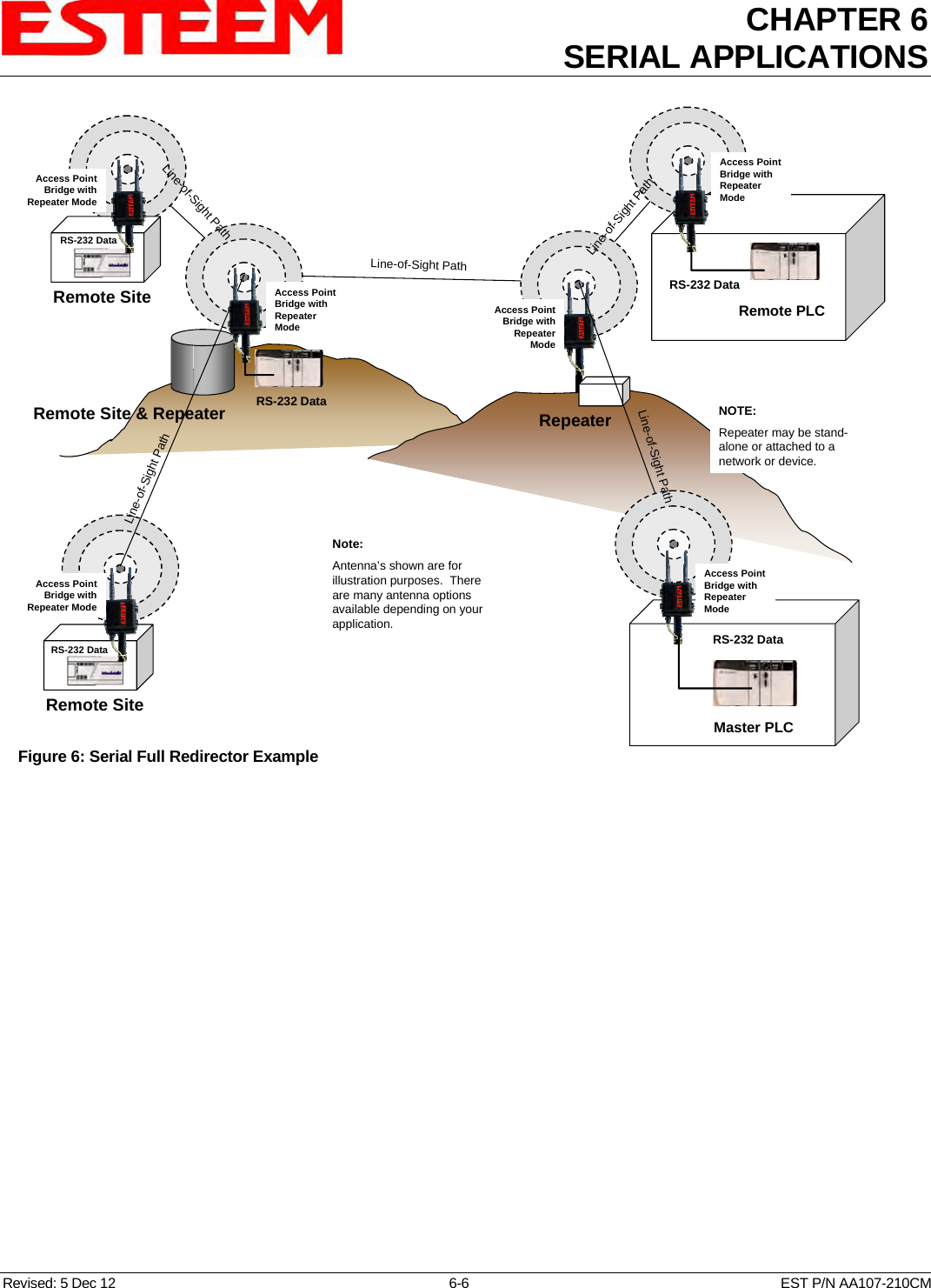
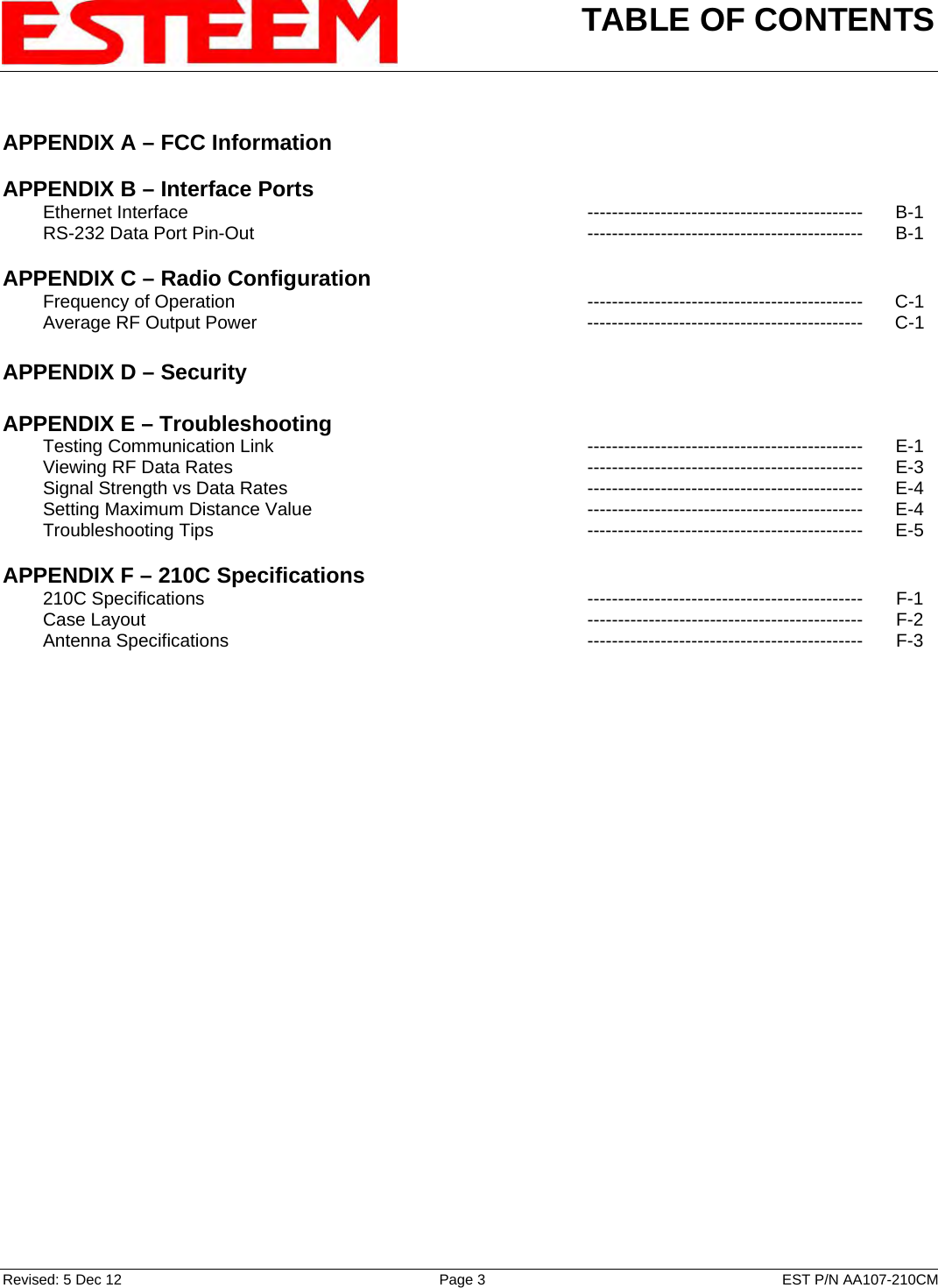
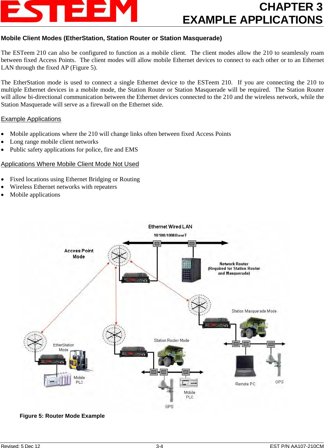
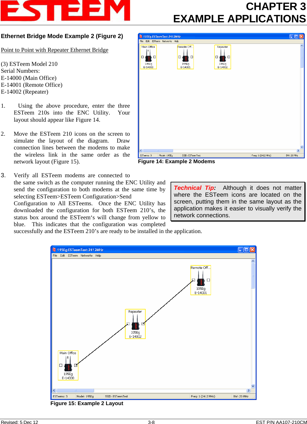
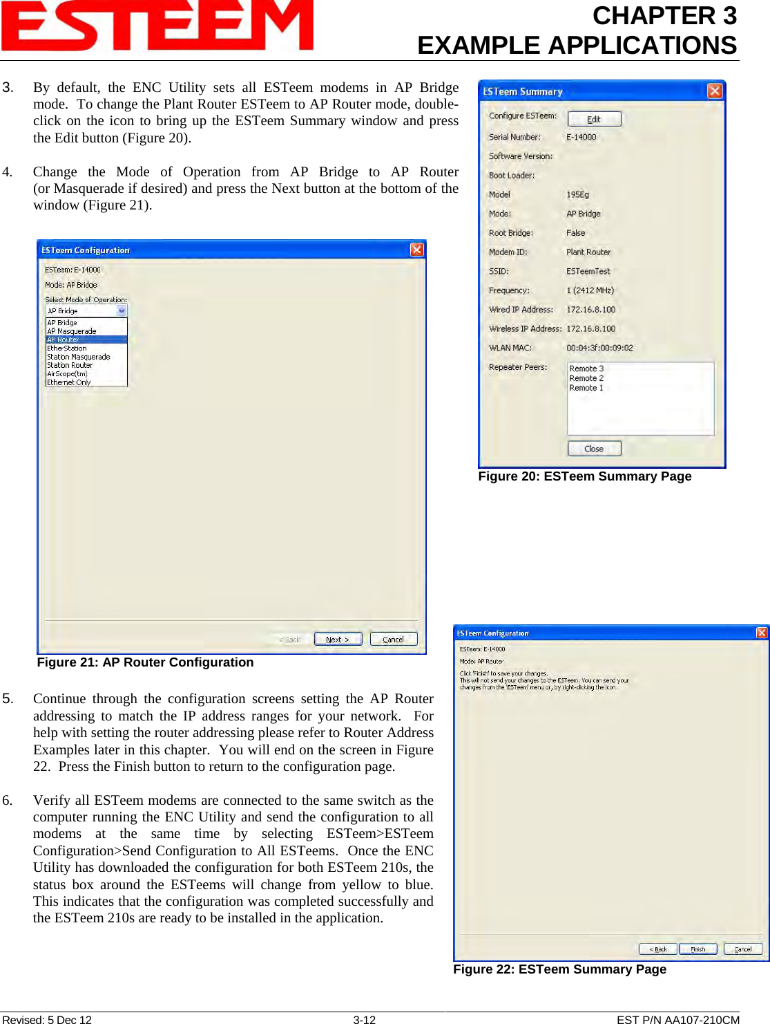
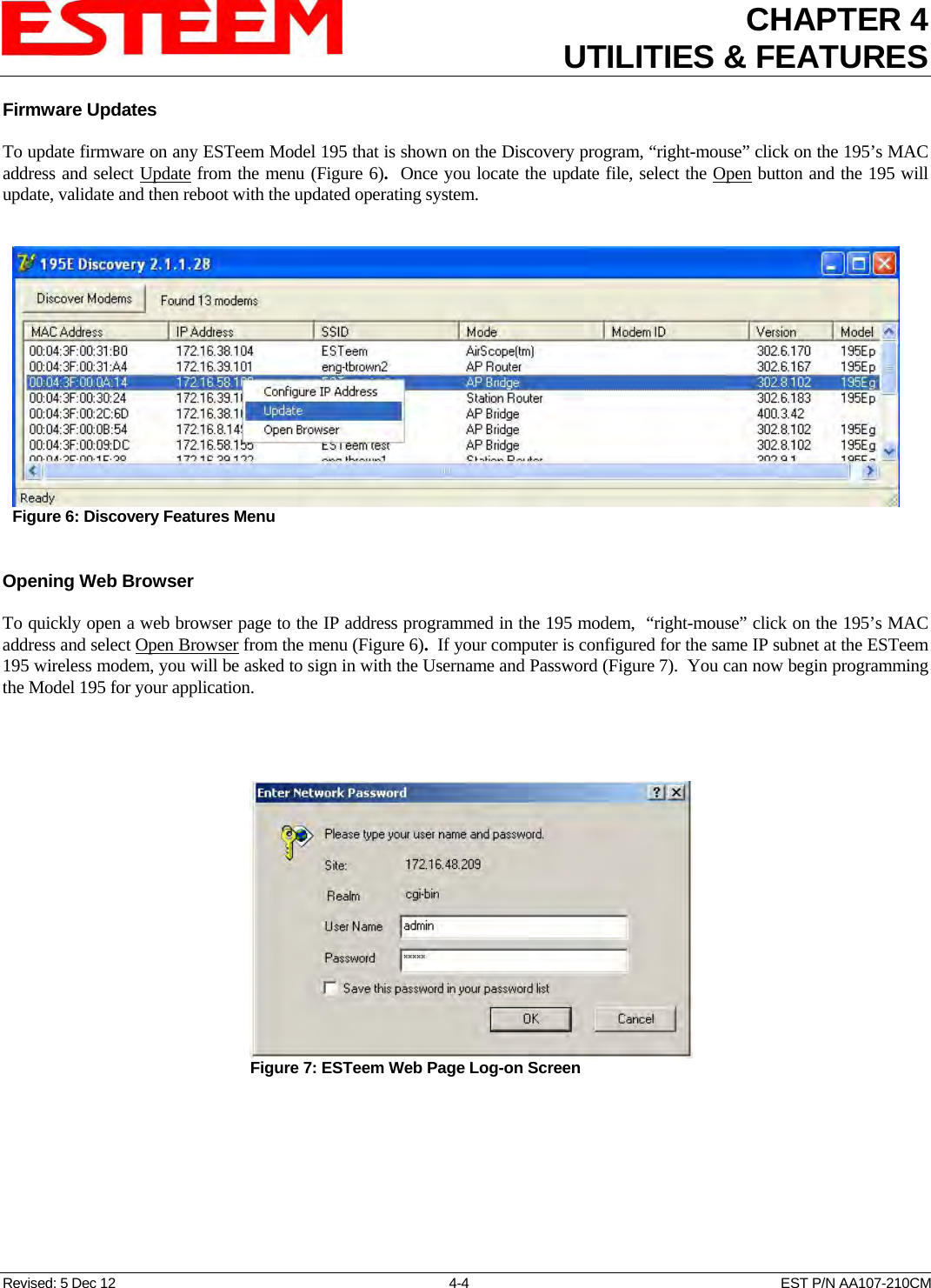
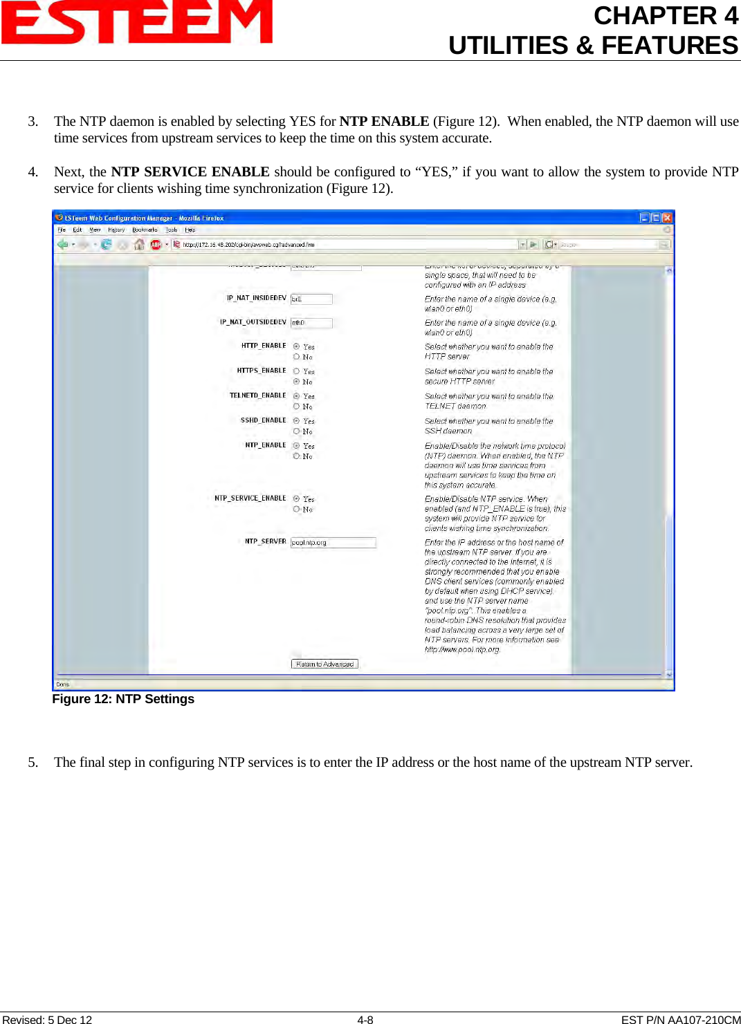
![CHAPTER 4UTILITIES & FEATURES [[ peer table entry ]] All entries in the Peer Table will have a device entry index, both ESTeem and other wireless devices EST-MIB::wirelessPeersNumber.0 Total number of peer entries in table wlan device EST-MIB::wirelessPeerTable.1.pDevice.1 index into the wirelessDeviceTable (each entry will have a unique number Peer MAC Address EST-MIB::wirelessPeerTable.1.pMacAddr.1 MAC address of peer isRepeater? EST-MIB::wirelessPeerTable.1.pRepeater.1 Is the peer an ESTeem repeater isAP? EST-MIB::wirelessPeerTable.1.pAP.1 Is the peer an Access Point isAssocSta? EST-MIB::wirelessPeerTable.1.pAssoc.1 Is the peer an Mobile Client isAdhoc? EST-MIB::wirelessPeerTable.1.pAdhoc.1 Is the peer an AdHoc Station (802.11 only) Frequency EST-MIB::wirelessPeerTable.1.pFreq.1 Frequency in MHz current rate set EST-MIB::wirelessPeerTable.1.pCurRates.1 Current Operating Rates last rx signal EST-MIB::wirelessPeerTable.1.pSignal.1 Receive Signal in –dBm last rx noise EST-MIB::wirelessPeerTable.1.pNoise.1 Background Noise in –dBm BSSID EST-MIB::wirelessPeerTable.1.pBssid.1 Basic Service Set ID (In Hex) SSID EST-MIB::wirelessPeerTable.1.pSSID.1 SSID in Text isValid? EST-MIB::wirelessPeerTable.1.pCurrent.1 True if peer info is for a “current” peer. last rx EST-MIB::wirelessPeerTable.1.pLastRxl.1 seconds since last received packet from peer last tx EST-MIB::wirelessPeerTable.1.pLastTx.1 seconds since last transmitted packet to peer current tx rate EST-MIB::wirelessPeerTable.1.pCurrentRate.1 current tx rate in bps. Downloading MIB Tables To download the MIB items listed above and import into your SNMP server, log into any ESTeem 210 and select the About page (Figure 20). Press the Download MIB Files hyperlink on the page and save the files to your computer. Figure 14: MIB Table Download Revised: 5 Dec 12 4-11 EST P/N AA107-210CM](https://usermanual.wiki/Electronic-Systems-Technology/ESTEEM210M/User-Guide-2062976-Page-40.png)