Electronic Systems Technology HZN216AP WIRELESS MODEM User Manual
Electronic Systems Technology WIRELESS MODEM Users Manual
Users Manual

ESTeemUser’sManual
HorizonSeries
ManualRevision2.0
January2017
ESTeem Industrial Wireless Solutions

Electronic Systems Technology, Inc.
Dba ESTeem Wireless Modems
Building B1
415 N. Quay Street
Kennewick, WA 99336
Phone: 509-735-9092
Fax: 509-783-5475
E-mail: market@esteem.com
Web Site: www.esteem.com
Copyright© 2017 by Electronic Systems Technology, Inc.
All rights reserved. Printed in the United States of America. No part of this publication may be reproduced, stored
in a retrieval system, or transmitted, in any form or by any means, electronic, mechanical, photocopying, recording,
or otherwise, without the prior written permission of Electronic Systems Technology.
Author: Date:
Name: Eric P. Marske
Title: Product Support Manager
Approved by: Date:
Name: Mike Eller
Title: President

PRODUCTWARRANTY
ESTeem Industrial Wireless Solutions Specifications subject to change without notice
415 North Quay Street Kennewick, WA 99336 www.esteem.com
Phone (509) 735-9092 Fax (509) 783-5475 Revised: 25 Jan 2017
Electronic Systems Technology, Inc. dba ESTeem Wireless Modems, (hereinafter ESTeem) expressly warrants its products as free
of manufacturing defects for a period of one year from the date of sale to first user/customer. THERE ARE NO OTHER
WARRANTIES, EXPRESS OR IMPLIED AND THERE IS EXPRESSLY EXCLUDED ALL WARRANTIES OF MERCHANTABILITY
OR FITNESS FOR A PARTICULAR PURPOSE. NO OTHER WARRANTY GIVEN BY ANY EMPLOYEE, AGENT, DISTRIBUTOR
OR OTHER PERSON WITH RESPECT TO THE PRODUCT SHALL BE BINDING ON ESTEEM.
LIMITATION OF LIABILITY:
ESTeem's liability shall be limited to refunding of purchase price, repair or replacement of product. IN NO EVENT SHALL ESTEEM
HAVE LIABILITY FOR CONSEQUENTIAL, INCIDENTAL, SPECIAL OR EXEMPLARY DAMAGES CAUSED DIRECTLY OR
INDIRECTLY BY THE PRODUCT, INCLUDING BUT NOT LIMITED TO ANY INTERRUPTION OF SERVICES, LOSS OF
BUSINESS OR ANTICIPATORY PROFITS. IN NO EVENT SHALL ESTEEM BE LIABLE FOR ANY DAMAGES WHATSOEVER
IN EXCESS OF THE PURCHASE PRICE OF THE PRODUCT.
In the event that a unit or part requires replacement or factory servicing, the following conditions apply:
a) Customer must obtain from ESTeem an authorized RMA (Return Materials Authorization) Number before shipment of
product or parts to ESTeem for any reason;
b) If the whole unit is shipped, it must be in its original carton and shipping components, or a carton and shipping
components supplied by ESTeem, or it parts only are shipped, they must be packaged and cushioned so as to prevent
damage in transit and shipped freight prepaid;
PRODUCT WILL BE CONSIDERED OUT OF WARRANTY IF:
a) If the product is damaged due to improper or abnormal use, abuse, mishandling, accident or improper maintenance or
failure to follow operating instruction;
b) If the product is defective as a result of sand, dirt, or water damage;
c) If any factory-sealed enclosure has been opened or shows evidence of an attempt to be opened;
d) If defects or damage are caused by the use of unauthorized parts or unauthorized service;
e) If the product has had its serial numbers altered or removed.
Warranty repair form must be accompanied by proof of user's purchase of unit. Product must be shipped to the manufacturer at the
following address:
ESTeem Wireless Modems
415 North Quay Street
Kennewick, Washington USA 99336
ADDITIONAL SERVICE:
If ESTeem releases an improvement update to firmware internal to the ESTeem unit during the 90-day period after the unit was
purchased by the first user/customer, ESTeem will update the applicable unit with the revised version at no charge other than for
UPS handling and shipping to and from your location to the ESTeem factory. Return of any such item must be accompanied with
proof of purchase.
TABLEOFCONTENTS
Revised:30Jan2017Page1ESTeemHorizonSeries
CHAPTER1–Introduction
BeforeYouBegin1‐1
HorizonOverview1‐1
HorizonConfigurationModes
AccessPointModes ‐‐‐‐‐‐‐‐‐‐‐‐‐‐‐‐‐‐‐‐‐‐‐‐‐‐‐‐‐‐‐‐‐‐‐‐‐‐‐‐‐‐‐‐‐ 1‐2
AccessPointPeer(Repeater)Mode ‐‐‐‐‐‐‐‐‐‐‐‐‐‐‐‐‐‐‐‐‐‐‐‐‐‐‐‐‐‐‐‐‐‐‐‐‐‐‐‐‐‐‐‐‐ 1‐3
Self‐HealingMeshNetwork ‐‐‐‐‐‐‐‐‐‐‐‐‐‐‐‐‐‐‐‐‐‐‐‐‐‐‐‐‐‐‐‐‐‐‐‐‐‐‐‐‐‐‐‐‐ 1‐4
Station(WiFiClient)Modes ‐‐‐‐‐‐‐‐‐‐‐‐‐‐‐‐‐‐‐‐‐‐‐‐‐‐‐‐‐‐‐‐‐‐‐‐‐‐‐‐‐‐‐‐‐ 1‐4
RS‐232SerialApplications ‐‐‐‐‐‐‐‐‐‐‐‐‐‐‐‐‐‐‐‐‐‐‐‐‐‐‐‐‐‐‐‐‐‐‐‐‐‐‐‐‐‐‐‐‐ 1‐5
CHAPTER2–StartingOut
ThreeConfigurationPhases2‐1
HorizonHardwareDescription2‐1
FrontPanelLayout ‐‐‐‐‐‐‐‐‐‐‐‐‐‐‐‐‐‐‐‐‐‐‐‐‐‐‐‐‐‐‐‐‐‐‐‐‐‐‐‐‐‐‐‐‐ 2‐2
AntennaConnectionOverview ‐‐‐‐‐‐‐‐‐‐‐‐‐‐‐‐‐‐‐‐‐‐‐‐‐‐‐‐‐‐‐‐‐‐‐‐‐‐‐‐‐‐‐‐‐ 2‐2
HorizonHardwareConfiguration2‐3
CHAPTER3–ExampleApplications
ModesofOperationDescriptionandExamples 3‐1
EthernetBridgeMode ‐‐‐‐‐‐‐‐‐‐‐‐‐‐‐‐‐‐‐‐‐‐‐‐‐‐‐‐‐‐‐‐‐‐‐‐‐‐‐‐‐‐‐‐‐ 3‐1
RouterModes ‐‐‐‐‐‐‐‐‐‐‐‐‐‐‐‐‐‐‐‐‐‐‐‐‐‐‐‐‐‐‐‐‐‐‐‐‐‐‐‐‐‐‐‐‐ 3‐3
MobileClientModes ‐‐‐‐‐‐‐‐‐‐‐‐‐‐‐‐‐‐‐‐‐‐‐‐‐‐‐‐‐‐‐‐‐‐‐‐‐‐‐‐‐‐‐‐‐ 3‐4
802.11AccessPointModes ‐‐‐‐‐‐‐‐‐‐‐‐‐‐‐‐‐‐‐‐‐‐‐‐‐‐‐‐‐‐‐‐‐‐‐‐‐‐‐‐‐‐‐‐‐ 3‐5
ProgrammingExamples3‐7
UsingESTeemNetworkConfiguration(ENC)Utility ‐‐‐‐‐‐‐‐‐‐‐‐‐‐‐‐‐‐‐‐‐‐‐‐‐‐‐‐‐‐‐‐‐‐‐‐‐‐‐‐‐‐‐‐‐ 3‐7
Example1–PointtoPointEthernetBridge ‐‐‐‐‐‐‐‐‐‐‐‐‐‐‐‐‐‐‐‐‐‐‐‐‐‐‐‐‐‐‐‐‐‐‐‐‐‐‐‐‐‐‐‐‐ 3‐9
Example2–PointtoPointEthernetBridgewithRepeater ‐‐‐‐‐‐‐‐‐‐‐‐‐‐‐‐‐‐‐‐‐‐‐‐‐‐‐‐‐‐‐‐‐‐‐‐‐‐‐‐‐‐‐‐‐ 3‐10
Example3–PointtoMultipointwithMeshRepeater ‐‐‐‐‐‐‐‐‐‐‐‐‐‐‐‐‐‐‐‐‐‐‐‐‐‐‐‐‐‐‐‐‐‐‐‐‐‐‐‐‐‐‐‐‐ 3‐11
Example4–PointtoMultipointRouterMode ‐‐‐‐‐‐‐‐‐‐‐‐‐‐‐‐‐‐‐‐‐‐‐‐‐‐‐‐‐‐‐‐‐‐‐‐‐‐‐‐‐‐‐‐‐ 3‐13
Example5–MobileClientMode ‐‐‐‐‐‐‐‐‐‐‐‐‐‐‐‐‐‐‐‐‐‐‐‐‐‐‐‐‐‐‐‐‐‐‐‐‐‐‐‐‐‐‐‐‐ 3‐15
Example6–802.11AccessPointMode ‐‐‐‐‐‐‐‐‐‐‐‐‐‐‐‐‐‐‐‐‐‐‐‐‐‐‐‐‐‐‐‐‐‐‐‐‐‐‐‐‐‐‐‐‐ 3‐16
RouterAddressingExamples ‐‐‐‐‐‐‐‐‐‐‐‐‐‐‐‐‐‐‐‐‐‐‐‐‐‐‐‐‐‐‐‐‐‐‐‐‐‐‐‐‐‐‐‐‐ 3‐17
CHAPTER4–UtilitiesandFeatures
ESTeemNetworkConfiguration(ENC)Utility ‐‐‐‐‐‐‐‐‐‐‐‐‐‐‐‐‐‐‐‐‐‐‐‐‐‐‐‐‐‐‐‐‐‐‐‐‐‐‐‐‐‐‐‐‐ 4‐1
ESTeemDiscoveryUtility ‐‐‐‐‐‐‐‐‐‐‐‐‐‐‐‐‐‐‐‐‐‐‐‐‐‐‐‐‐‐‐‐‐‐‐‐‐‐‐‐‐‐‐‐‐ 4‐1
FirmwareUpdates ‐‐‐‐‐‐‐‐‐‐‐‐‐‐‐‐‐‐‐‐‐‐‐‐‐‐‐‐‐‐‐‐‐‐‐‐‐‐‐‐‐‐‐‐‐ 4‐3
SettingLocalTime ‐‐‐‐‐‐‐‐‐‐‐‐‐‐‐‐‐‐‐‐‐‐‐‐‐‐‐‐‐‐‐‐‐‐‐‐‐‐‐‐‐‐‐‐‐ 4‐4
ConfiguringTimeServer ‐‐‐‐‐‐‐‐‐‐‐‐‐‐‐‐‐‐‐‐‐‐‐‐‐‐‐‐‐‐‐‐‐‐‐‐‐‐‐‐‐‐‐‐‐ 4‐5
VLANOperation ‐‐‐‐‐‐‐‐‐‐‐‐‐‐‐‐‐‐‐‐‐‐‐‐‐‐‐‐‐‐‐‐‐‐‐‐‐‐‐‐‐‐‐‐‐ 4‐6

TABLEOFCONTENTS
Revised:30Jan2017Page2ESTeemHorizonSeries
IGMPSnooping ‐‐‐‐‐‐‐‐‐‐‐‐‐‐‐‐‐‐‐‐‐‐‐‐‐‐‐‐‐‐‐‐‐‐‐‐‐‐‐‐‐‐‐‐‐ 4‐6
ModbusTCPGPS/RadioMonitoring ‐‐‐‐‐‐‐‐‐‐‐‐‐‐‐‐‐‐‐‐‐‐‐‐‐‐‐‐‐‐‐‐‐‐‐‐‐‐‐‐‐‐‐‐‐ 4‐10
CHAPTER5–WebConfiguration
LoggingIntoWebConfigurationManager5‐1
WebConfigurationManager
TopMenu ‐‐‐‐‐‐‐‐‐‐‐‐‐‐‐‐‐‐‐‐‐‐‐‐‐‐‐‐‐‐‐‐‐‐‐‐‐‐‐‐‐‐‐‐‐ 5‐1
SettingModemIDField ‐‐‐‐‐‐‐‐‐‐‐‐‐‐‐‐‐‐‐‐‐‐‐‐‐‐‐‐‐‐‐‐‐‐‐‐‐‐‐‐‐‐‐‐‐ 5‐2
StatusMenu ‐‐‐‐‐‐‐‐‐‐‐‐‐‐‐‐‐‐‐‐‐‐‐‐‐‐‐‐‐‐‐‐‐‐‐‐‐‐‐‐‐‐‐‐‐ 5‐3
SystemLogScreen ‐‐‐‐‐‐‐‐‐‐‐‐‐‐‐‐‐‐‐‐‐‐‐‐‐‐‐‐‐‐‐‐‐‐‐‐‐‐‐‐‐‐‐‐‐ 5‐4
SetupScreen ‐‐‐‐‐‐‐‐‐‐‐‐‐‐‐‐‐‐‐‐‐‐‐‐‐‐‐‐‐‐‐‐‐‐‐‐‐‐‐‐‐‐‐‐‐ 5‐5
AdvancedConfigurationScreen ‐‐‐‐‐‐‐‐‐‐‐‐‐‐‐‐‐‐‐‐‐‐‐‐‐‐‐‐‐‐‐‐‐‐‐‐‐‐‐‐‐‐‐‐‐ 5‐5
BackupScreen ‐‐‐‐‐‐‐‐‐‐‐‐‐‐‐‐‐‐‐‐‐‐‐‐‐‐‐‐‐‐‐‐‐‐‐‐‐‐‐‐‐‐‐‐‐ 5‐6
RestoreScreen ‐‐‐‐‐‐‐‐‐‐‐‐‐‐‐‐‐‐‐‐‐‐‐‐‐‐‐‐‐‐‐‐‐‐‐‐‐‐‐‐‐‐‐‐‐ 5‐6
SoftwareUpdate ‐‐‐‐‐‐‐‐‐‐‐‐‐‐‐‐‐‐‐‐‐‐‐‐‐‐‐‐‐‐‐‐‐‐‐‐‐‐‐‐‐‐‐‐‐ 5‐7
SystemReboot ‐‐‐‐‐‐‐‐‐‐‐‐‐‐‐‐‐‐‐‐‐‐‐‐‐‐‐‐‐‐‐‐‐‐‐‐‐‐‐‐‐‐‐‐‐ 5‐7
CHAPTER6–SerialConfigurationandApplications
UsingRS‐232ProgrammingPort6‐1
UsingRS‐232DataPort
SerialConnections ‐‐‐‐‐‐‐‐‐‐‐‐‐‐‐‐‐‐‐‐‐‐‐‐‐‐‐‐‐‐‐‐‐‐‐‐‐‐‐‐‐‐‐‐‐ 6‐3
SerialConfiguration ‐‐‐‐‐‐‐‐‐‐‐‐‐‐‐‐‐‐‐‐‐‐‐‐‐‐‐‐‐‐‐‐‐‐‐‐‐‐‐‐‐‐‐‐‐ 6‐3
CHAPTER7–BridgeLinksandMeshNetworking
ESTeemMeshNetwork7‐1
Configuration ‐‐‐‐‐‐‐‐‐‐‐‐‐‐‐‐‐‐‐‐‐‐‐‐‐‐‐‐‐‐‐‐‐‐‐‐‐‐‐‐‐‐‐‐‐ 7‐1
RapidSpanningTreeProtocol(RSTP)
Overview ‐‐‐‐‐‐‐‐‐‐‐‐‐‐‐‐‐‐‐‐‐‐‐‐‐‐‐‐‐‐‐‐‐‐‐‐‐‐‐‐‐‐‐‐‐ 7‐4
Phases ‐‐‐‐‐‐‐‐‐‐‐‐‐‐‐‐‐‐‐‐‐‐‐‐‐‐‐‐‐‐‐‐‐‐‐‐‐‐‐‐‐‐‐‐‐ 7‐4
PriorityandPathCost ‐‐‐‐‐‐‐‐‐‐‐‐‐‐‐‐‐‐‐‐‐‐‐‐‐‐‐‐‐‐‐‐‐‐‐‐‐‐‐‐‐‐‐‐‐ 7‐4
RootBridge ‐‐‐‐‐‐‐‐‐‐‐‐‐‐‐‐‐‐‐‐‐‐‐‐‐‐‐‐‐‐‐‐‐‐‐‐‐‐‐‐‐‐‐‐‐ 7‐4
RedundantBackup
RedundantMasterConfiguration ‐‐‐‐‐‐‐‐‐‐‐‐‐‐‐‐‐‐‐‐‐‐‐‐‐‐‐‐‐‐‐‐‐‐‐‐‐‐‐‐‐‐‐‐‐ 7‐5
CHAPTER8–AntennaSetups
AntennaandCableConfigurations
Horizon2.4GHzAntennaandCableConfigurations ‐‐‐‐‐‐‐‐‐‐‐‐‐‐‐‐‐‐‐‐‐‐‐‐‐‐‐‐‐‐‐‐‐‐‐‐‐‐‐‐‐‐‐‐‐ 8‐1
Horizon900MHzAntennaandCableConfigurations ‐‐‐‐‐‐‐‐‐‐‐‐‐‐‐‐‐‐‐‐‐‐‐‐‐‐‐‐‐‐‐‐‐‐‐‐‐‐‐‐‐‐‐‐‐ 8‐2
Horizon4.9GHzAntennaandCableConfigurations ‐‐‐‐‐‐‐‐‐‐‐‐‐‐‐‐‐‐‐‐‐‐‐‐‐‐‐‐‐‐‐‐‐‐‐‐‐‐‐‐‐‐‐‐‐ 8‐3
Horizon5.8GHzAntennaandCableConfigurations ‐‐‐‐‐‐‐‐‐‐‐‐‐‐‐‐‐‐‐‐‐‐‐‐‐‐‐‐‐‐‐‐‐‐‐‐‐‐‐‐‐‐‐‐‐ 8‐4

TABLEOFCONTENTS
Revised:30Jan2017Page3ESTeemHorizonSeries
WeatherproofingCoaxialCableConnections 8‐5
AntennaDiversity8‐5
AssemblingtheAA195PMOutdoorPoleMountingKit 8‐6
GroundingProcedure8‐11
FresnelZone 8‐12
APPENDIXA–FCCInformation
APPENDIXB–InterfacePorts
EthernetInterface ‐‐‐‐‐‐‐‐‐‐‐‐‐‐‐‐‐‐‐‐‐‐‐‐‐‐‐‐‐‐‐‐‐‐‐‐‐‐‐‐‐‐‐‐‐ B‐1
ConfiguringDHCPServer ‐‐‐‐‐‐‐‐‐‐‐‐‐‐‐‐‐‐‐‐‐‐‐‐‐‐‐‐‐‐‐‐‐‐‐‐‐‐‐‐‐‐‐‐‐ B‐1
RS‐232ProgrammingPortPin‐Out ‐‐‐‐‐‐‐‐‐‐‐‐‐‐‐‐‐‐‐‐‐‐‐‐‐‐‐‐‐‐‐‐‐‐‐‐‐‐‐‐‐‐‐‐‐ B‐2
RS‐232DataPortPin‐Out ‐‐‐‐‐‐‐‐‐‐‐‐‐‐‐‐‐‐‐‐‐‐‐‐‐‐‐‐‐‐‐‐‐‐‐‐‐‐‐‐‐‐‐‐‐ B‐2
APPENDIXC–RadioConfiguration
FrequencyofOperation ‐‐‐‐‐‐‐‐‐‐‐‐‐‐‐‐‐‐‐‐‐‐‐‐‐‐‐‐‐‐‐‐‐‐‐‐‐‐‐‐‐‐‐‐‐ C‐1
RFDataRateConfiguration ‐‐‐‐‐‐‐‐‐‐‐‐‐‐‐‐‐‐‐‐‐‐‐‐‐‐‐‐‐‐‐‐‐‐‐‐‐‐‐‐‐‐‐‐‐ C‐1
RFBandwidths ‐‐‐‐‐‐‐‐‐‐‐‐‐‐‐‐‐‐‐‐‐‐‐‐‐‐‐‐‐‐‐‐‐‐‐‐‐‐‐‐‐‐‐‐‐ C‐2
RFDataRatesandThroughputChart ‐‐‐‐‐‐‐‐‐‐‐‐‐‐‐‐‐‐‐‐‐‐‐‐‐‐‐‐‐‐‐‐‐‐‐‐‐‐‐‐‐‐‐‐‐ C‐4
SettingRFOutputPower ‐‐‐‐‐‐‐‐‐‐‐‐‐‐‐‐‐‐‐‐‐‐‐‐‐‐‐‐‐‐‐‐‐‐‐‐‐‐‐‐‐‐‐‐‐ C‐12
APPENDIXD–Security
APPENDIXE–Troubleshooting
TestingCommunicationLink ‐‐‐‐‐‐‐‐‐‐‐‐‐‐‐‐‐‐‐‐‐‐‐‐‐‐‐‐‐‐‐‐‐‐‐‐‐‐‐‐‐‐‐‐‐ E‐1
ViewingPeerTable ‐‐‐‐‐‐‐‐‐‐‐‐‐‐‐‐‐‐‐‐‐‐‐‐‐‐‐‐‐‐‐‐‐‐‐‐‐‐‐‐‐‐‐‐‐ E‐1
RadioCloningProcedure ‐‐‐‐‐‐‐‐‐‐‐‐‐‐‐‐‐‐‐‐‐‐‐‐‐‐‐‐‐‐‐‐‐‐‐‐‐‐‐‐‐‐‐‐‐ E‐2
TroubleshootingTips ‐‐‐‐‐‐‐‐‐‐‐‐‐‐‐‐‐‐‐‐‐‐‐‐‐‐‐‐‐‐‐‐‐‐‐‐‐‐‐‐‐‐‐‐‐ E‐3
APPENDIXF–Horizon2.4Specifications
Horizon2.4(216AN)Specifications ‐‐‐‐‐‐‐‐‐‐‐‐‐‐‐‐‐‐‐‐‐‐‐‐‐‐‐‐‐‐‐‐‐‐‐‐‐‐‐‐‐‐‐‐‐ F‐1
CaseDiagram ‐‐‐‐‐‐‐‐‐‐‐‐‐‐‐‐‐‐‐‐‐‐‐‐‐‐‐‐‐‐‐‐‐‐‐‐‐‐‐‐‐‐‐‐‐ F‐2
AntennaSpecifications ‐‐‐‐‐‐‐‐‐‐‐‐‐‐‐‐‐‐‐‐‐‐‐‐‐‐‐‐‐‐‐‐‐‐‐‐‐‐‐‐‐‐‐‐‐ F‐3
APPENDIXG–Horizon900Specifications
Horizon900(216AD)Specifications ‐‐‐‐‐‐‐‐‐‐‐‐‐‐‐‐‐‐‐‐‐‐‐‐‐‐‐‐‐‐‐‐‐‐‐‐‐‐‐‐‐‐‐‐‐ G‐1
CaseDiagram ‐‐‐‐‐‐‐‐‐‐‐‐‐‐‐‐‐‐‐‐‐‐‐‐‐‐‐‐‐‐‐‐‐‐‐‐‐‐‐‐‐‐‐‐‐ G‐2
AntennaSpecifications ‐‐‐‐‐‐‐‐‐‐‐‐‐‐‐‐‐‐‐‐‐‐‐‐‐‐‐‐‐‐‐‐‐‐‐‐‐‐‐‐‐‐‐‐‐ G‐3
APPENDIXH–Horizon4.9Specifications
Horizon4.9(216AP)Specifications ‐‐‐‐‐‐‐‐‐‐‐‐‐‐‐‐‐‐‐‐‐‐‐‐‐‐‐‐‐‐‐‐‐‐‐‐‐‐‐‐‐‐‐‐‐ H‐1
CaseDiagram ‐‐‐‐‐‐‐‐‐‐‐‐‐‐‐‐‐‐‐‐‐‐‐‐‐‐‐‐‐‐‐‐‐‐‐‐‐‐‐‐‐‐‐‐‐ H‐2
AntennaSpecifications ‐‐‐‐‐‐‐‐‐‐‐‐‐‐‐‐‐‐‐‐‐‐‐‐‐‐‐‐‐‐‐‐‐‐‐‐‐‐‐‐‐‐‐‐‐ H‐3
APPENDIXI–Horizon5.8Specifications
Horizon5.8(216AA‐LP)Specifications ‐‐‐‐‐‐‐‐‐‐‐‐‐‐‐‐‐‐‐‐‐‐‐‐‐‐‐‐‐‐‐‐‐‐‐‐‐‐‐‐‐‐‐‐‐ I‐1
CaseDiagram ‐‐‐‐‐‐‐‐‐‐‐‐‐‐‐‐‐‐‐‐‐‐‐‐‐‐‐‐‐‐‐‐‐‐‐‐‐‐‐‐‐‐‐‐‐ I‐2
AntennaSpecifications ‐‐‐‐‐‐‐‐‐‐‐‐‐‐‐‐‐‐‐‐‐‐‐‐‐‐‐‐‐‐‐‐‐‐‐‐‐‐‐‐‐‐‐‐‐ I‐3
CHAPTER1
INTRODUCTION
Revised: 25 Jan 17 1-1 ESTeem Horizon Series
BEFOREYOUBEGIN
ThankyouandcongratulationsonyourpurchaseoftheESTeemHorizon
SeriesWirelessEthernetModem!Thismanualwaswrittentohelpboththe
firsttimeandadvanceduseroftheHorizontoconfigurethewireless
modemforyourapplication.IfthisisyourfirsttimeconfiguringtheHorizon
andyouwouldliketogetgoingassoonaspossible,werecommendusing
theESTeemResourceCDprovidedwiththemodem.TheResourceCDwill
providethesoftwareutilitiesandguideyouthroughtheconfigurationof
thewirelessmodemforyourapplication.
TheESTeemHorizonSeriesofwirelessEthernetnetworkinghardwareare
verysophisticatednetworkingdevices.Tokeepthemanualusablyshort,manyof
theapplicationdescriptionsandprogrammingdetailsassumetheuserhasagood
workingknowledgeofthefollowingnetworkconcepts:
GeneralEthernetnetworkingandtheconfigurationofLANtopologies
CommonEthernetterminologyandacronyms
TCP/IPnetworkprotocolstructureandhowtoconfigureTCP/IPnetworksandsubnets
HowtoidentifyandsettheTCP/IPaddressonyourcomputer
Haveadministratorprivilegestothecomputerandnetworkyouareconfiguring
Ifusingroutingprotocols,youmustbeabletoidentifyandconfigurethenetworkrouters,gatewaysandfirewalls
YoumustbefamiliarwithusingwebbrowsersoftwaresuchasInternetExplorer,NetscapeorMozilla
Ifyouareunfamiliarwithanyoftheabovenetworkingconcepts,youmayneedtocontactyournetworkadministratorfor
assistance.
HORIZONOVERVIEW
TheESTeemHorizonisaseriesofwirelessLAN
transceiversthatcanbeusedtobuildmanytypes
ofWirelessLocalAreaNetworks(WLAN).The
wirelessmodemsinHorizonseriescanprovideRF
dataratesupto300MbpsandhaveanRS‐232
serialportforlegacydevicenetworks.TheModel
Horizonisaverysophisticatednetworkingdevice
thatcanbeconfiguredformultiplemodesof
operationdependingupontheneedsofthe
wirelessandwiredLANsystem.Thefollowing
configurationmodesareprovidedasanoverview
ofthebasicnetworktypes,asallpossiblenetwork
configurationscannotbelisted.Forfurtherhelpin
selectingthecorrectnetworktype,pleasereferto
Chapter4ofthisUser’sManualorcallCustomer
Supportat509‐735‐9092.
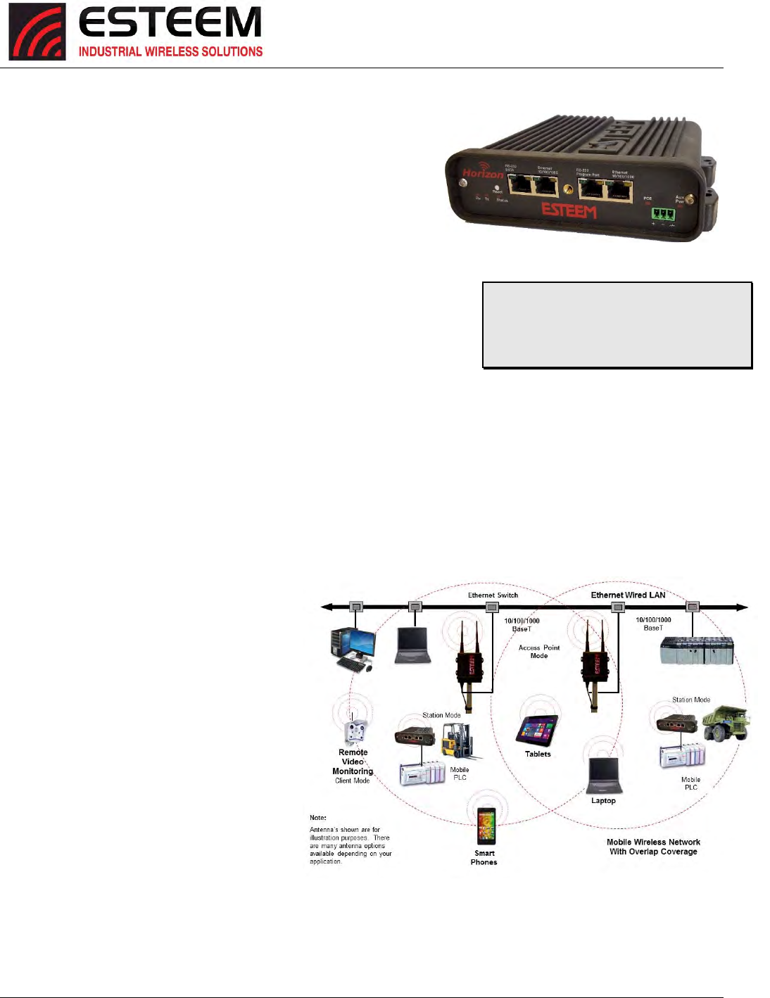
Figure1:ESTeemHorizonSeries
ThroughoutthisUser’sManualare
“TechnicalTips”inboxeslikethisthathave
beenaddedtohelpanswerthemost
commonlyaskedquestions.
Figure2:AccessPointBridgeDiagram
CHAPTER1
INTRODUCTION
Revised: 25 Jan 17 1-2 ESTeem Horizon Series
CONFIGURATIONMODES
TheHorizoncanbeconfiguredformultiple
modesofoperationwithoutanychangestothe
hardware.Thefollowingarebriefdescriptions
oftheconfigurationmodes.Fordetailed
descriptionsandsuggestedapplicationsfor
eachmode,pleaserefertoChapter4.
AccessPointModes
WhentheHorizonisconfiguredasanAccess
Pointitwillprovideawirelessbridgeformobile
clientssuchasHorizonorModel195Emodems
inclientmodesorWi‐Fidevices.Multiple
AccessPointscanbephysicallyconnectedto
thesamenetwork(LAN)orthrougharadiolink
usingtheAccessPointPeermodetoprovide
overlapping,seamlessEthernetcommunication
formobiledevices.
1. AccessPointBridgeMode
AnESTeemHorizoninAccessPointBridgemodewillbothprovidewirelessaccesstomobileclients(AccessPoint)and
bridgeallEthernetdataconnectedtotheEthernetports.TheAPBridgemodewillpassallnetworktrafficbetween
connecteddevicesincludingglobalnetworkbroadcasts.(SeeFigure2)
2. AccessPointRouterMode
InthismodetheESTeemHorizonwill
functionasarouterbetweenwired
Ethernetnetworks,connectedtothe
Horizon’sEthernetport,andthe
wirelessclientsinthenetwork.Asin
allstandardrouterconfigurations,
thewirelessandwiredEthernet
networkswillneedtobeonseparate
subnets.TheHorizoninAccessPoint
Routermodewillpassnetworktraffic
forconnecteddevicesbutwillblock
globalnetworkbroadcastsfromthe
wirednetwork.Thismodeof
operationshouldbeusedinsteadof
theAccessPointBridgemodewhena
separationbetweennetworksis
requiredortheESTeemisconnected
tolargerLANNetworksthatwill
continuouslysendglobalnetwork
broadcasts(Figure3).
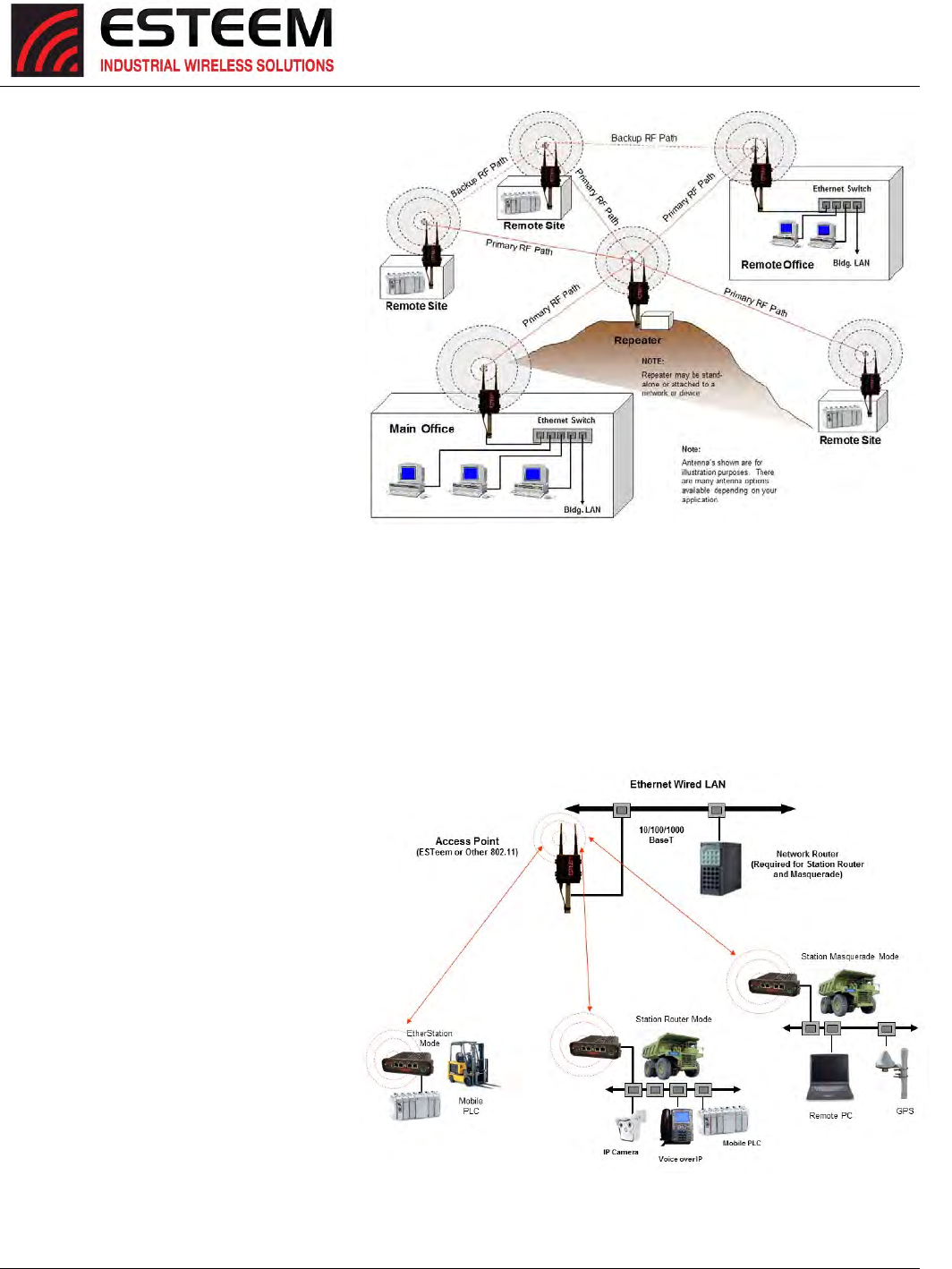
Figure3:PeerModeDiagram
Figure4:AccessPointMasqueradeDiagram
CHAPTER1
INTRODUCTION
Revised: 25 Jan 17 1-3 ESTeem Horizon Series
3. AccessPointMasqueradeMode
TheAccessPointMasquerademodeisaspecialuseoftheAccessPointmodewheretheHorizonwillconnectmobile
clientsintoasinglestaticIPaddressonawirednetwork.Datarequestsfromthewirelessnetworkwillbeprocessed
throughtheAccessPointMasquerademodem,butanyrequestfromthewiredEthernetnetworktodevicesonthe
wirelessnetworkwillberejectedsimilartotheoperationofa“firewall”.TheHorizonwillhidealltheIPaddresses
connectedonthewirelesslink.YouwouldusethismodeofoperationifHorizonisconnecteddirectlytotheInternet
withastaticIPaddress(DSL,T1,etc.)andyouwantthewirelessclientstoaccesstheinformationthroughtheHorizon
(Figure4).ThismodeshouldalsobeusedforattachingtheHorizontoanetworkwherefewIPaddressesareavailable
orafirewallforthewirelessclientsisrequired.
AccessPointPeer(Repeater)Mode
TheAccessPointPeerconnectionisauniqueenhancementoftheESTeemHorizonseries.TheAccessPointRepeater
canbeusedwithanyoftheaboveAccessPointmodes.Withthisrepeaterfeatureenabled,theAccessPointsdonot
havetobehardwiredtogetheronthesamephysicalLANtoprovideseamlessEthernetcommunicationforroaming
clients.InadditiontogreatlyextendingtheAccessPointcanopyrange,theHorizonwillalsobridgeanyEthernetdevice
orEthernetnetworkconnectedtotheunitoverthissamewirelessEthernetnetwork.Thismodegivestheuserthe
featuresofapointtomulti‐pointbridgenetworkbutalsoallowstheHorizonintheClientmodetosimultaneouslyroam
underthenetworkcanopy.
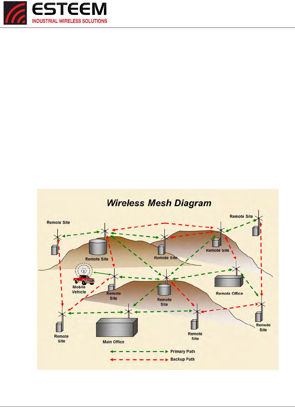
Figure5:MeshNetworkDiagram

CHAPTER1
INTRODUCTION
Revised: 25 Jan 17 1-4 ESTeem Horizon Series
Self‐HealingMeshNetwork
IfmultipleAccessPointRepeaterroutesareconfiguredtothesamedestinationESTeem,theHorizonwillcreatea
“self‐healing”meshnetworkbyautomaticallyre‐routingdatathroughalternatepathstoreachitsdestinationifthe
primarypathisinoperable.Theroutingandpriorityofalternatepathsiscompletelyuserconfigurable.(SeeFigure5)
Station(Client)Modes
1. EtherStationMode
WhentheHorizonisconfiguredintheEtherStationmodeandattachedtoasingleEthernetDevice,theHorizonwill
emulatean802.11wirelesscardinfunctionalityforcommunicationasamobileclient.TheHorizonwillseamlessroam
undertheradiocanopyofAccessPointsandcanprovidegreatlyincreasedrangeoveraWirelessLANCardformobile
Ethernetdevicessuchasvehicles,forklifts,cranes,etc(Figures2‐4).
2. StationRouterMode
TheStationRoutermodewillalsofunctionsasamobileclient,similartoEtherStation,butwillallowmultipleEthernet
devicestobeconnectedtoasingleHorizon(Figure4).TheHorizonwillfunctionasarouterbetweenthewirelessclient
modeandthewiredEthernetdevicesconnectedtotheEthernetport.SimilarinconfigurationtotheAccessPointRouter
mode,thewirelessandwiredEthernetnetworkswillneedtobeonseparatesubnets.Tocommunicatefromwireless
networktodevicesonthewiredStationRouternetwork,aseparaterouter(connectedtotheEthernetsideoftheAccess
Point)isrequired.ThismodewouldbeusedwheremultipleEthernetdeviceswillbeconnectedtoasingleHorizonina
mobileclientapplicationandtheconnectedEthernetdeviceswillneedtobeaccessiblefromtheAccessPoint’sLAN
network.
3. StationMasqueradeMode
TheStationMasquerademodeisanothercasemultipledeviceswillbeconnectedtoasingleESTeeminamobileorclient
application.However,unliketheStationRoutermode,theStationMasqueradewillconsolidateallconnectedEthernet
devicestoasingleIPaddressonthenetwork.ThedevicesconnectedtotheStationMasqueradewillbeabletoaccess
informationfromboththewirelessandwiredLAN,butwillbeinaccessibletheotherwaysimilarinapplicationtoa
firewall.ThismodewouldbeusedwheremultipleEthernetdeviceswillbeconnectedtoasingleHorizoninamobile
applicationandtheIPaddressesforeachdevicewillbehiddenfromtheLANconnectedtotheAP.SeeFigure4.
CHAPTER1
INTRODUCTION
Revised: 25 Jan 17 1-5 ESTeem Horizon Series
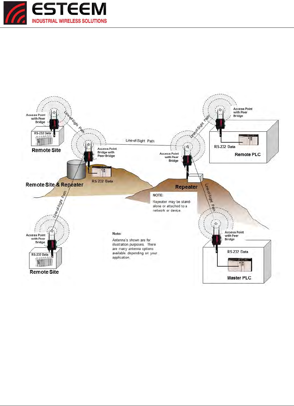
RS‐232SerialApplications
TheESTeemHorizonisinstalledwithanRS‐232dataportforserialdataapplicationsrunoverthebroadbandlink(Figure
6).Theserialoverbroadbandnetworkcanbeusedinapoint‐to‐pointorpoint‐to‐multi‐pointapplicationfornetworking
serial(RS‐232C)devices,providingserialconnectionstolegacyhardwareinanewEthernetnetworkorprovidingforhigh‐
bandwidthdevices(suchasVideoorVoiceoverIP)inanexistingserialnetwork.
TobeginsetupofyourwirelessEthernetnetwork,continuetoChapter2‐StaringOutofthisUser’sManual.
Figure6:Multi‐pointSerialDiagram
CHAPTER2
STARTINGOUT
Revised: 27 Jun 16 2-1 ESTeem Horizon Series
OVERVIEW
TherearethreemainphasestopreparetheESTeemHorizonforoperationinawirelessnetwork:
Phase1‐DeterminethecorrectmodeofoperationfortheHorizoninthewirelessnetwork.TheESTeemHorizonisa
sophisticatednetworkingdevicethatcanbeconfiguredformultiplemodesofoperation.Determiningthecorrectmodeof
operationfortheESTeemHorizonisthefirststep.Chapter3ofthisUser’sManualdetailsthemodesofoperationand
applicationswhereeachwouldbeused.
Phase2‐ProgramtheESTeemforoperationinthewirelessnetwork.OncethecorrectmodeofoperationfortheESTeemhas
beendetermined,theHorizoncanbeprogrammedforthewirelessnetwork.TosimplifytheprogrammingoftheHorizon,
ESTeemhascreatedanewsoftwareutilitycalledtheESTeemNetworkConfiguration(ENC)Utilitywhichisusedtographically
configuretheprimaryandbackupcommunicationroutesbetweenradiomodemsinthenetwork.TheENCUtilitycanbe
installedfromtheESTeemResourceDiskorfromtheESTeemwebsite(www.esteem.com).Chapter4(UtilitiesandFeatures)of
thisUser’sManualwillguideyouintheinstallationofthesoftwareandgiveabriefoverviewofoperationoftheENCUtility,but
adetailedUser’sGuideisavailablebothontheESTeemResourceDiskandintheHelpsectionoftheprogramitself.
TheESTeemHorizoncanalsobeprogrammedthroughtheinternalWebinterface(discussedindetailinChapter5)ifyoudonot
haveaccesstotheENCUtility.
Phase3‐InstalltheESTeemhardwareandtestcommunication.AftertheESTeemHorizonprogramming,installthehardware
ineachremotelocation.Chapter8ofthisUser’sManualdescribestheantennaspecifications,mountingoptionsandthe
configurationofthepolemountinghardwarefortheESTeem.Forinstructionsontestingandtroubleshootingthewirelesslink,
refertoAppendixF(Troubleshooting).
HORIZONHARDWARELAYOUT
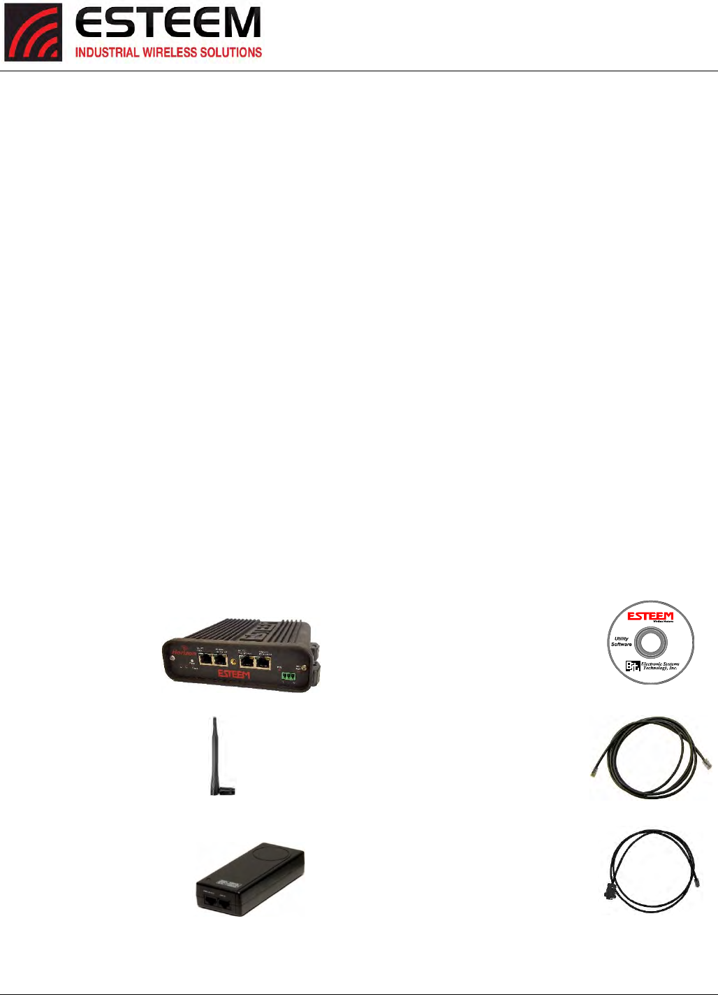
Tobegintheconfiguration,unpacktheESTeemHorizonshippingboxesandlocatetheitemsbelowforinitialconfiguration.Take
afewminutestoinventoryyourequipmentbeforeyouproceed.ReportanymissingordamageditemstoCustomerSupport
(509‐735‐9092)assoonaspossible.EachnodeinyourESTeemHorizon’snetworkmayhavedifferenthardwarecomponents
baseduponthefinalinstallationlocation(i.e.Outdoor,Indoor,Point‐to‐pointorMuti‐Point).Antennatypes,cablelengths,
powersuppliesmaybedifferent,butthefollowingitemswillberequiredforbasicsetup:
HorizonRadio
AA109ResourceDisk
Antenna
(AA01SDisplayed)
(2)EthernetCables
PowerSupply
(AA175.2Displayed)
SerialInterfaceCable
(AA6021.1)
Note:Youraccessorymodelnumbersmayvaryfromtheabove,butyouwillneedtolocateeachofaboveitemstocontinue
configuration.
CHAPTER2
STARTINGOUT
Revised: 27 Jun 16 2-2 ESTeem Horizon Series
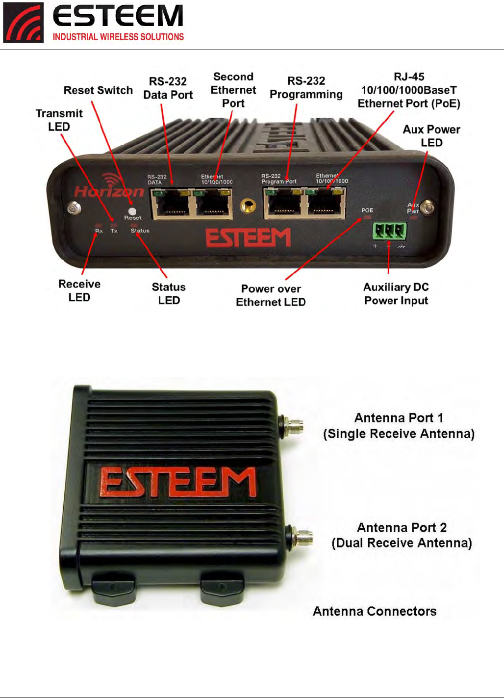
Figure2:HorizonAntennaOverview
Figure1:HorizonFrontPanelOverview
CHAPTER2
STARTINGOUT
Revised: 27 Jun 16 2-3 ESTeem Horizon Series
HORIZONHARDWARECONFIGURATION
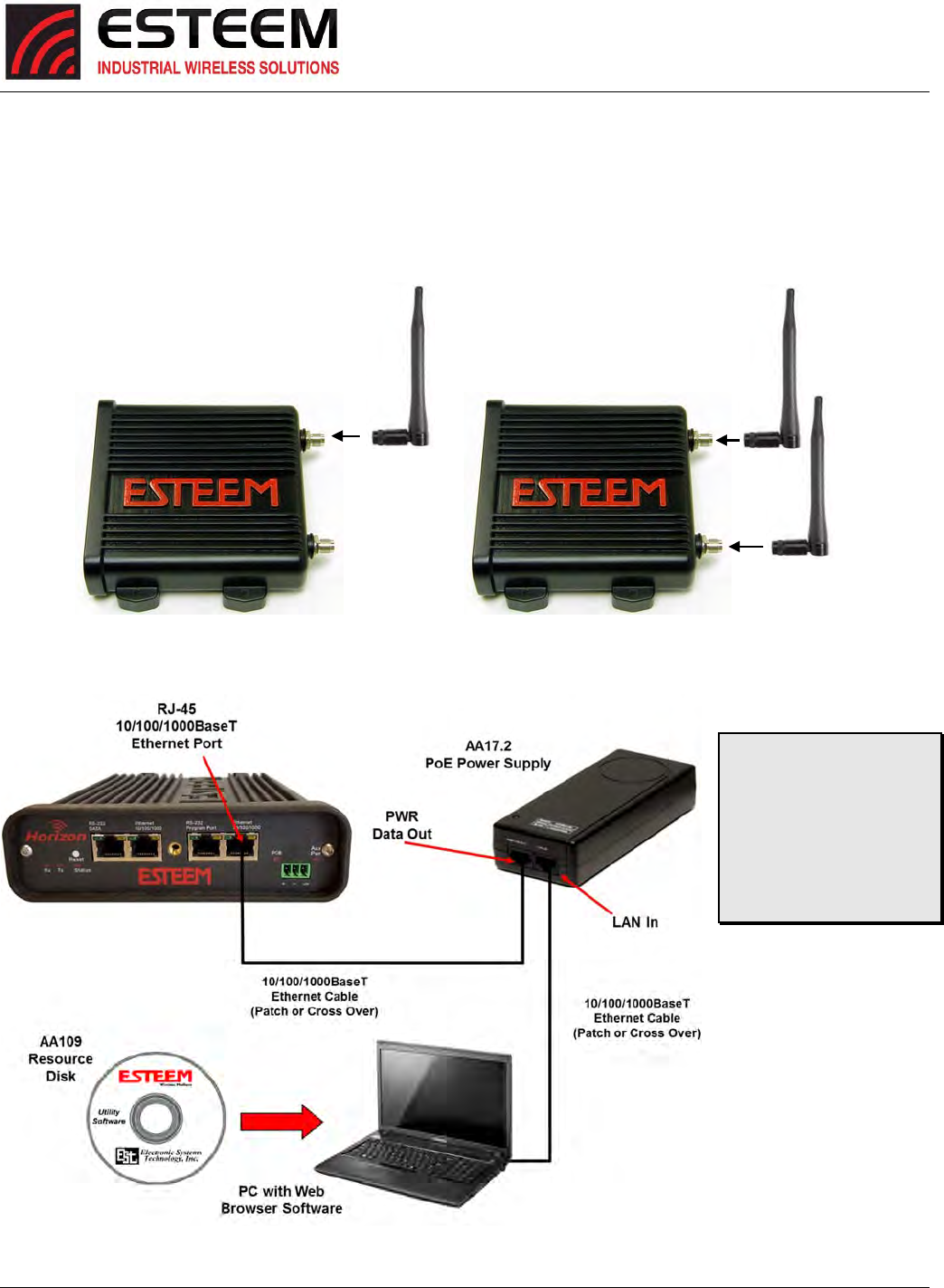
ThefollowingstepsshouldbecompletedtobeginconfigurationoftheESTeemHorizon:
1. ConnecttheantennatotheantennaconnectorontheHorizon(Figure3).ForasingleantennauseAntennaPort1and
connectbothifusingdualantennas.
2. AssembletheHorizonhardwareasshowninFigure4.
Figure3:AntennaConfigurationDiagram
TechnicalTips:
1.ConfiguretheHorizon
priortomounting.
2.Attachantennatothe
Horizonbeforepowering
up.
Figure4:HardwareConfigurationDiagram
Leave
Open
Single Antenna
Configuration Dual Antenna
Configuration
CHAPTER3
EXAMPLEAPPLICATIONS
Revised: 27 Jun 16 3-1 ESTeem Horizon Series
MODESOFOPERATION
TheESTeemHorizonisasophisticatedwirelessnetworkingdevicethatcanbeconfiguredformultiplemodesofoperation.
DeterminingthecorrectmodeofoperationfortheESTeemisthefirststepincreatingareliablewirelessnetwork.Thischapter
willexplaineachmodeofoperation,provideexampleapplicationsanddetailedprogramminginformationforeachmode.
Pleasereviewthefollowingmodesofoperations.Ifyoudonotseeanexampleofyourapplication,pleasecontactESTeem
supportat509‐735‐9092forhelpinselectingyourmodeofoperation.
EthernetBridgeMode(APBridge)
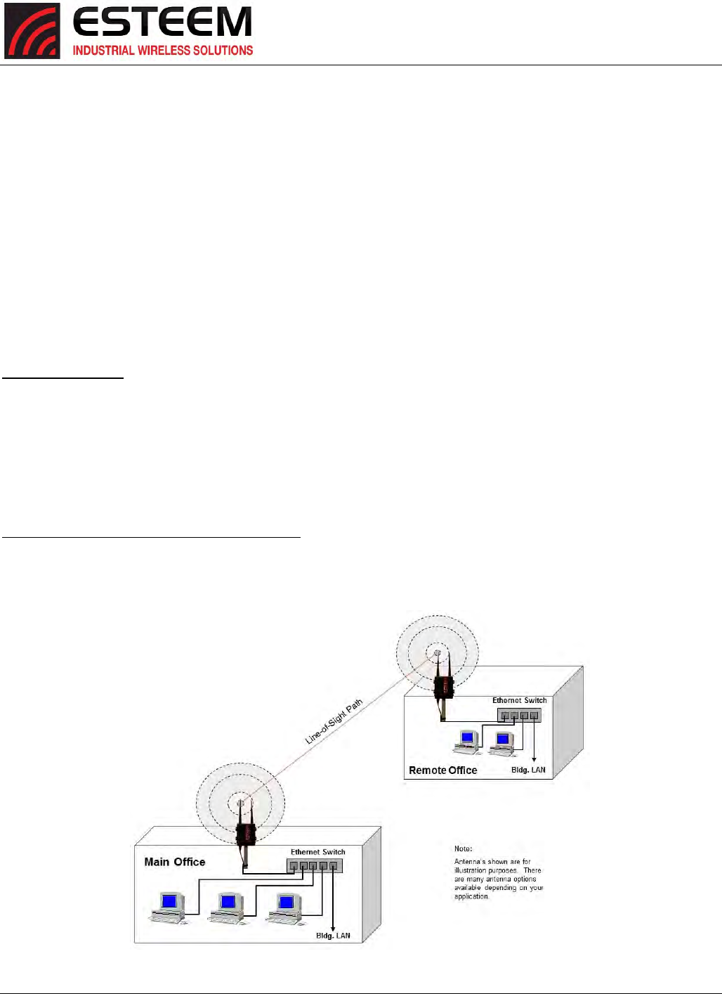
ThemostcommonlyusedmodeofoperationwiththeESTeemHorizonistheEthernetbridgemode.TheEthernetbridgemode
willconnecttwoormoreESTeemHorizon’swhilepassingallnetworktrafficthatarrivesinboththewirelessandconnected
Ethernetports;includingallglobalnetworktraffic(Figure1).ThismodewillworkinmostwirelessapplicationsoftheHorizon
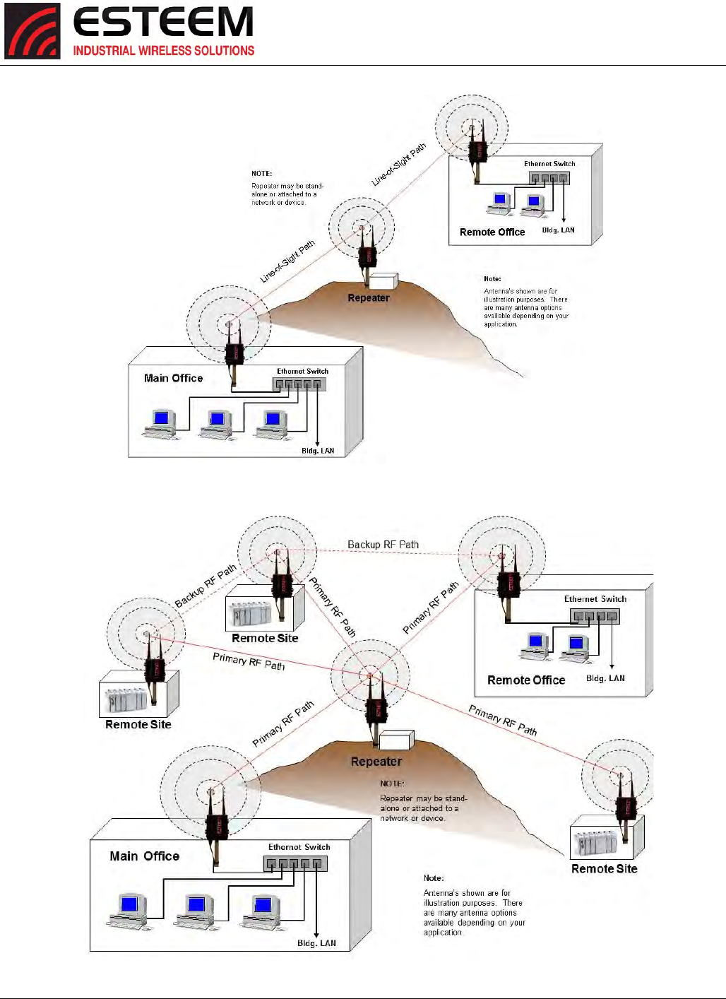
towirelesslyconnecttwoormoreremoteEthernetdevicesornetworks.TheEthernetbridgemodeisalsousedinrepeating
(Figure2)andinself‐healingMeshnetworks(Figure3)forfixed(non‐mobile)applications.
ExampleApplications
BuildingtobuildingremotewirelessLANnetworks
PointtopointwirelessEthernetcommunicationdevices
Multi‐pointwirelessEthernetnetworks
RemoteSupervisoryControlandDataAcquisition(SCADA)networks
Redundant,self‐healingMeshnetworks
FixedlocationswithmobileESTeemHorizon’s
ApplicationsWhereEthernetBridgeModeNotUsed
Mobileapplications(seeMobileClients)
ConnectionstolargeEthernettrafficnetworkssuchaslargeofficebuildingsorplantnetworks(seeRoutermodes)
Figure1:PointtoPointExample
CHAPTER3
EXAMPLEAPPLICATIONS
Revised: 27 Jun 16 3-2 ESTeem Horizon Series
Figure3:MultipointBridgewithMeshNetworking
Figure2:EthernetBridgewithRepeater
CHAPTER3
EXAMPLEAPPLICATIONS
Revised: 27 Jun 16 3-3 ESTeem Horizon Series
RouterModes(APRouterandAPMasquerade)
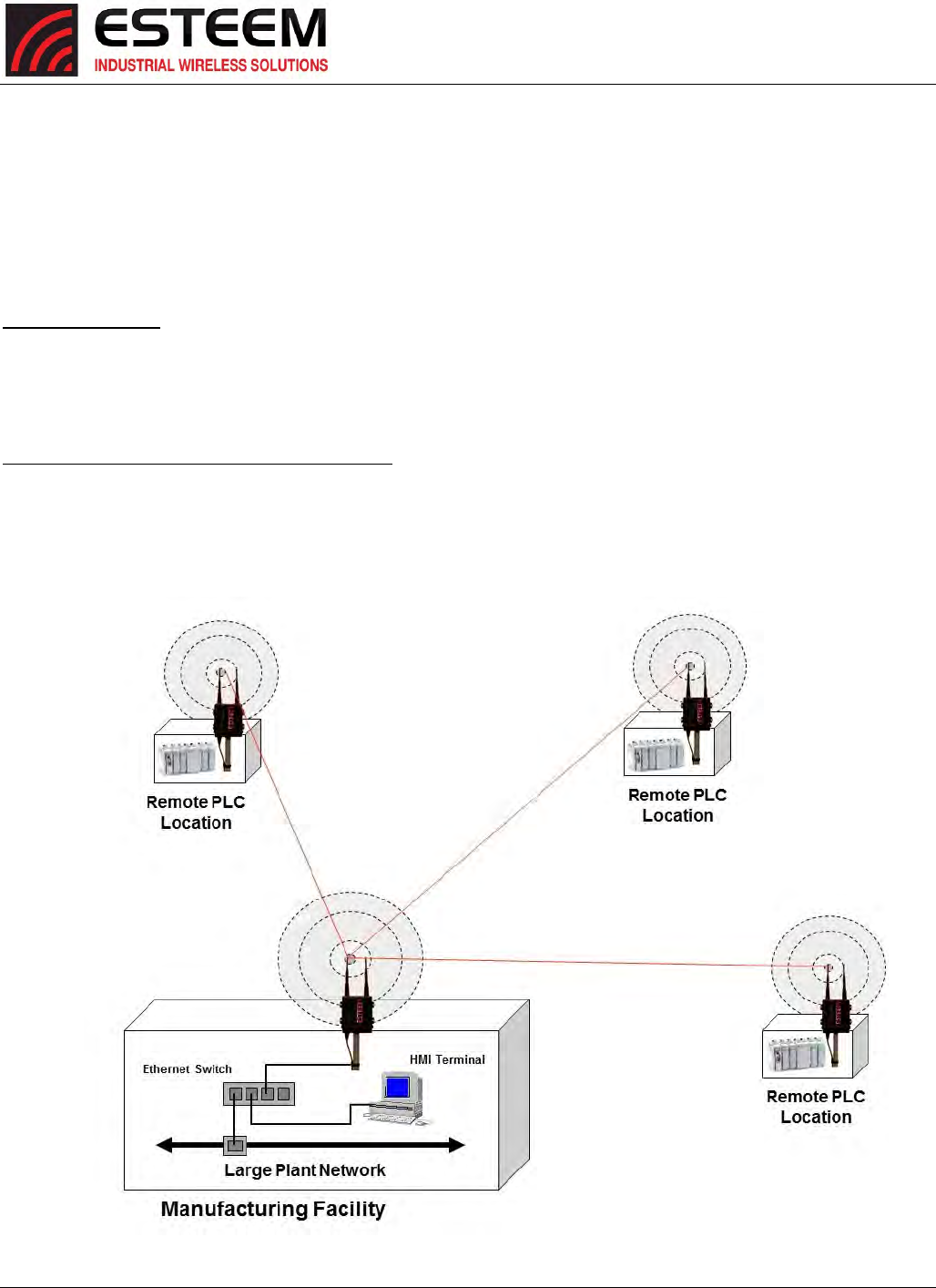
TheESTeemHorizoncanbeconfiguredasanetworkrouterornetworkfirewallbetweentheEthernetLANconnectionandthe
wirelessnetworkofremotelocations.TheroutermodesareusedtolimitthenetworktrafficfromabusyEthernetnetwork
connectiontoonlythosespecificIPaddressusedonthewirelessnetwork(seeFigure4).TheEthernetroutermode(APRouter)
willallowbi‐directionalcommunicationfromtheEthernetLANconnectiontothewirelessnetwork.TheEthernetfirewallmode
(APMasquerade)willallowEthernetdevicesinthewirelessnetworktorequestinformationfromtheEthernetLANnetwork
andreceivearesponse,butnotrafficcanbegeneratedfromtheEthernetLANside.
ExampleApplications
WirelessEthernetnetworksconnectedtolargecompanyorplantEthernetLANnetworks(APRouter)
WirelessEthernetnetworkswitharequirementfornetworkisolationfromtheplantorcompanynetwork(APRouter)
SharedEthernetconnectiontodirectInternetservice(DSL,Cable,T1,etc.)(APMasquerade)
ApplicationsWhereEthernetRouterModeNotUsed
Mobileapplications(seeMobileClients)
SimplenetworkconnectionsonlyusingasingleIPnetworksubnet(seeEthernetBridgemodes)
Figure4:RouterModeExample
CHAPTER3
EXAMPLEAPPLICATIONS
Revised: 27 Jun 16 3-4 ESTeem Horizon Series
MobileClientModes(EtherStation,StationRouterorStationMasquerade)
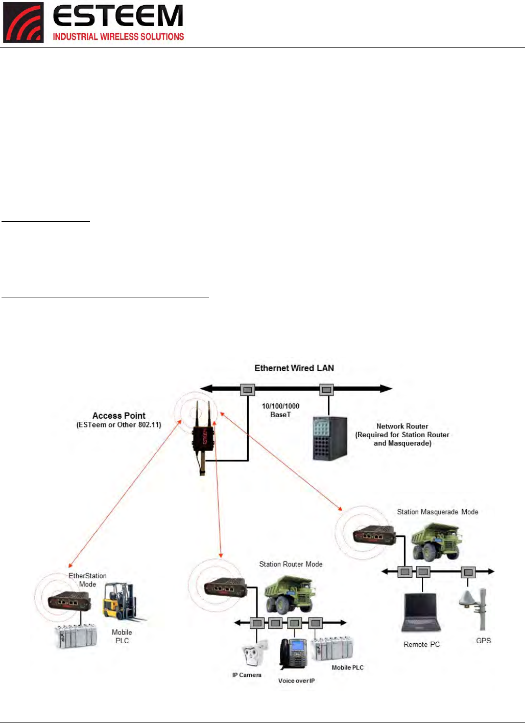
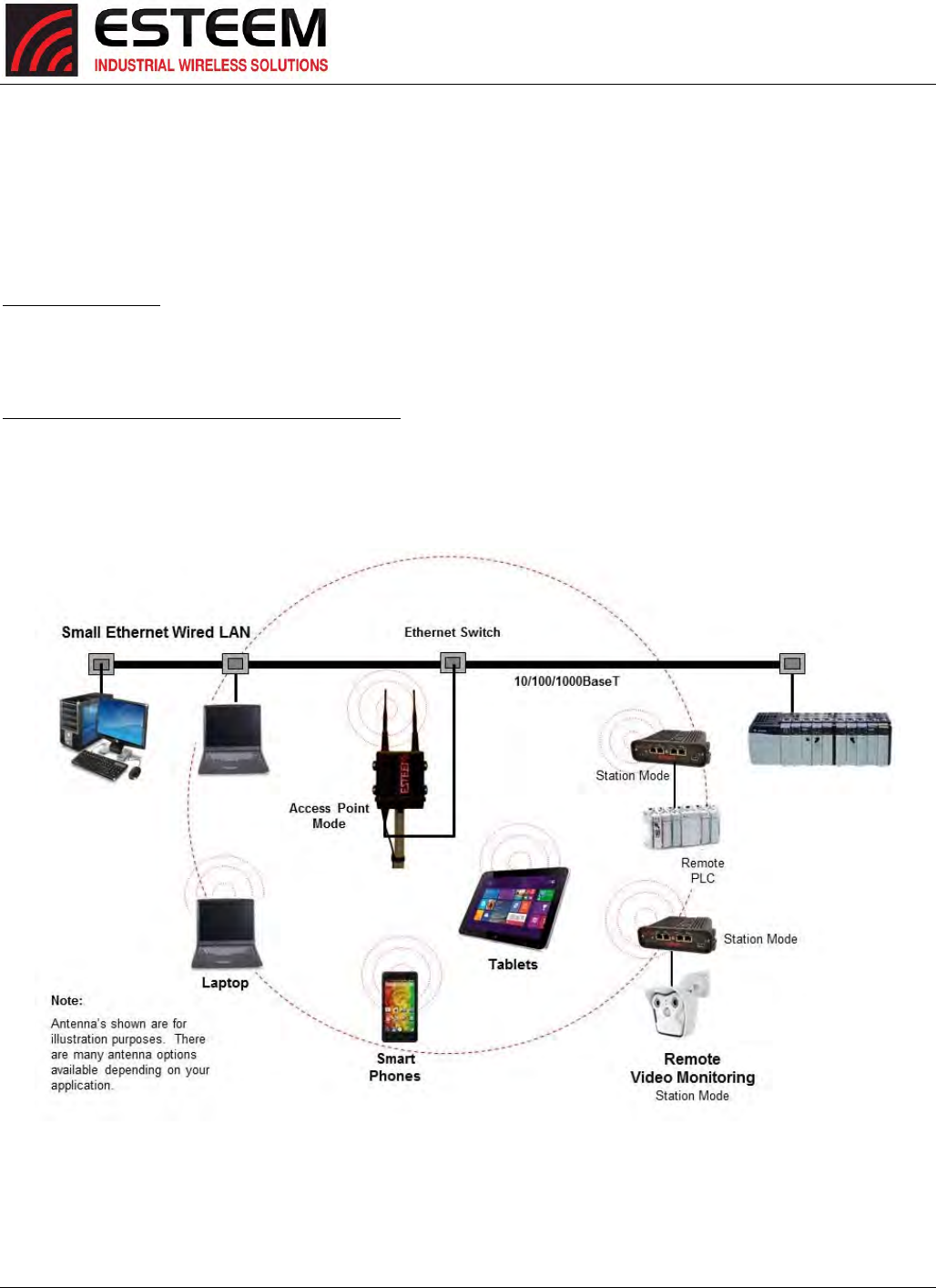
TheESTeemHorizoncanalsobeconfiguredtofunctionasamobileclient.TheclientmodesallowtheHorizontoseamlessly
roambetweenfixedAccessPoints.TheseAccessPointscaneitherbeESTeemHorizonwirelessmodemsconfiguredinoneof
thethreeAccessPointmodes(APBridge,APRouterorAPMasquerade–seeabove)oranyIEEE802.11(Wi‐Fi).Theclient
modeswillallowmobileEthernetdevicestoconnecttoeachotherortoanEthernetLANthroughthefixedAP(Figure5).
TheEtherStationmodeisusedtoconnectasingleEthernetdevicetotheESTeemHorizon.IfyouareconnectingtheHorizon
tomultipleEthernetdevicesinamobilemode,theStationRouterorStationMasqueradewillberequired.TheStationRouter
willallowbi‐directionalcommunicationbetweentheEthernetdevicesconnectedtotheHorizonandthewirelessnetwork,
whiletheStationMasqueradewillserveasafirewallontheEthernetside.
ExampleApplications
MobileapplicationswheretheHorizonwillchangelinksoftenbetweenfixedAccessPoints
Longrangemobileclientnetworks
Publicsafetyapplicationsforpolice,fireandEMS
ApplicationsWhereMobileClientModeNotUsed
FixedlocationsusingEthernetBridgingorRouting
WirelessEthernetnetworkswithrepeaters
Fi
g
ure5:RouterModeExam
p
le
CHAPTER3
EXAMPLEAPPLICATIONS
Revised: 27 Jun 16 3-5 ESTeem Horizon Series
802.11AccessPointModes(APBridge,APRouterorAPMasquerade)
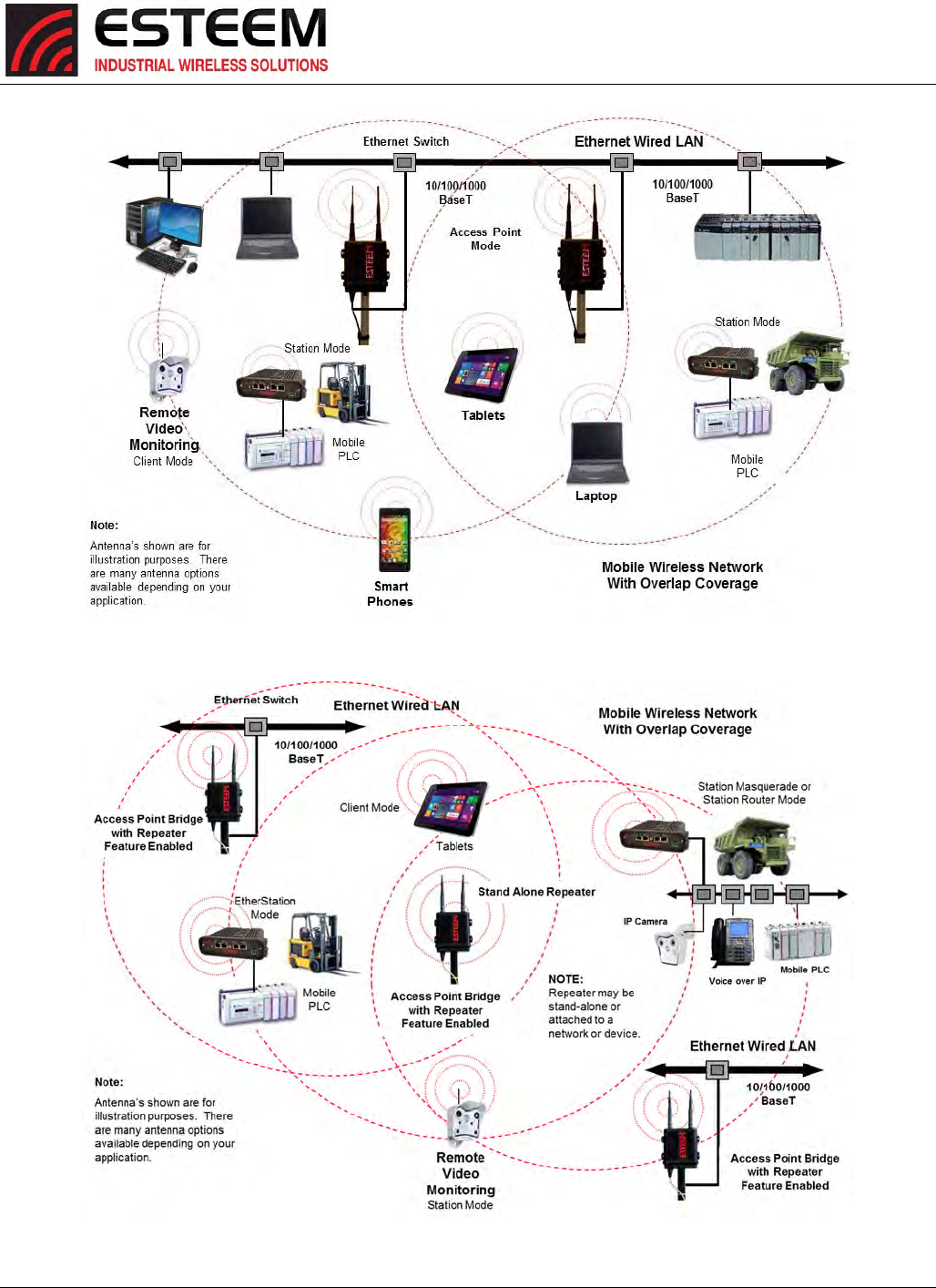
TheESTeemHorizoncanbeconfiguredasahighpower802.11AccessPoint(AP).TheIEEE802.11n/g/bAccessPoint(AP)
functionalityisavailableinallthreeoftheAccessPointmodes(APBridge,APRouterorAPMasquerade).TheAccessPoint
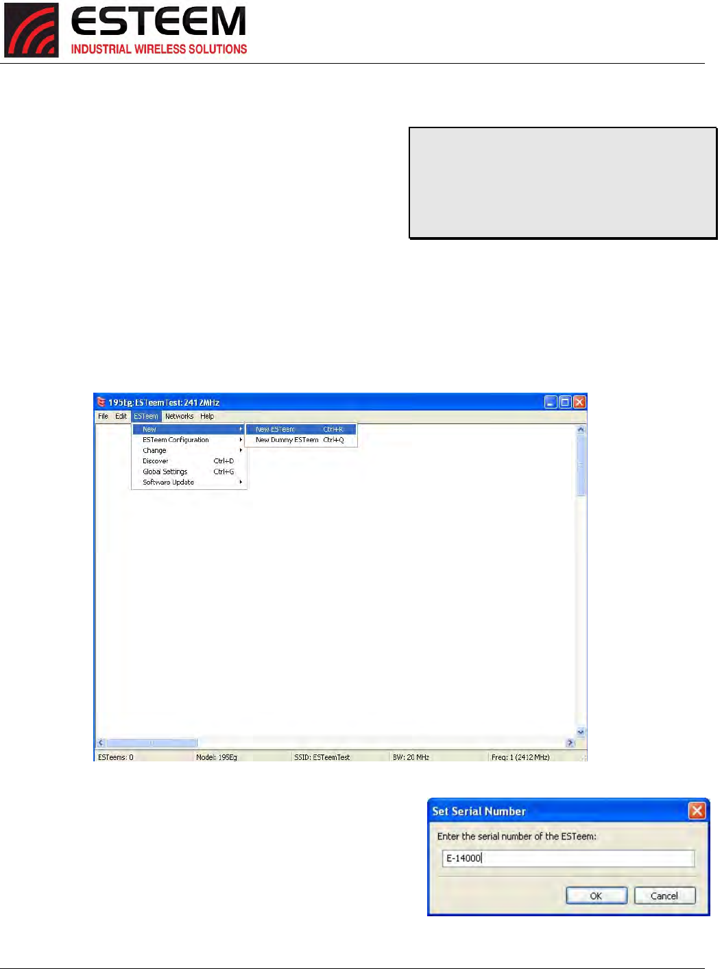
modewillprovideeitherasinglewirelessconnection(Figure6)oroverlappingcoverage(Figure7)tocreatea“canopy”of
wirelesscoveragefor802.11devices.TheESTeemHorizoninAPmodecanfunctionasbothanEthernetbridgeorrouterand
802.11APsimultaneously(Figure8).
ExampleApplications
Industrial,longrange802.11(Wi‐Fi)networks
HybridnetworksofEthernetbridging/routingandmobileclientaccess
ApplicationsWhereAccessPoint(AP)ModeNotUsed
Mobileapplications
Figure6:SingleAccessPointNetwork
CHAPTER3
EXAMPLEAPPLICATIONS
Revised: 27 Jun 16 3-6 ESTeem Horizon Series
Figure7:OverlappingAccessPointCoverage
Figure8:AccessPointandEthernetBridge
CHAPTER3
EXAMPLEAPPLICATIONS
Revised: 27 Jun 16 3-7 ESTeem Horizon Series
PROGRAMMINGEXAMPLES
OncethemodeofoperationfortheESTeemhasbeendetermined,you
arenowreadytoprogramtheHorizonforuse.ESTeemhascreateda
simplifiednetworkprogrammingutilitycalltheESTeemNetwork
Configuration(ENC)Utility.ThisENCUtilitywillbeusedinallthe
followingprogrammingexamples.Fordetailedinstructionson
installingtheENCUtility,pleaserefertotheUser’sGuide(foundinthe
ESTeemResourceCDorUtilityprogramitself)orChapter4ofthis
User’sManual
AddingEsteem’stoENCUtilityandChangingName
EachoftheexampleapplicationswillusethefollowingproceduretoaddandrenameESTeemHorizon’s.
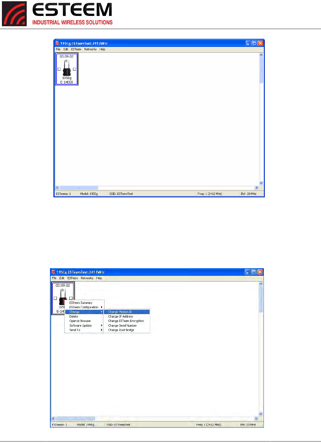
1. ConsulttheENCUtility’sUserGuideonhowthecreateanewwirelessnetwork.Onceyouhaveablanknetwork
configurationpage(Figure9),selectESTeemfromthemenuitemstodisplaythedropdownmenu,thenselectNew>New
ESTeem.
2. EnterintheESTeemHorizonserialnumbersusedfortheexample
(forexampleenterZ‐14000intheSetSerialNumberBox)andpress
theOKbutton(Figure10).TheENCUtilitywilllookuptheESTeem
Horizon’sserialnumberinthedatabaseandmatchthecorrect
WirelessLANMAC(WLANMAC)addresstothemodem.ThisWLAN
MACaddresswillbedisplayedabovethemodemsymbolonthe
screen(Figure11).
TechnicalTip:TheENCUtilitycalculatesthewireless
linkinformationbaseduponexactESTeemserial
numbers.Theserialnumberslistedinthefollowing
examplesareforexampleonly.Enterthecorrect
ESTeemserialnumbersforyourapplication.
Figure9:AddingESTeemtoBlankENCConfigurationPage
Figure10:EntertheSerialNumber
CHAPTER3
EXAMPLEAPPLICATIONS
Revised: 27 Jun 16 3-8 ESTeem Horizon Series
3. TochangethenameoftheESTeemHorizonfromtheWLANMACaddressto“MainOffice”(oranyotherlocationname)
tomatchtheexampleconfiguration,Right‐MouseclickontheESTeemiconandselectChange>ChangeModemID(Figure
12).Enter“MainOffice”inthepop‐upwindowandselectOK.
4.DuplicatetheaboveprocedureforeachESTeemHorizonaddedtothenetwork.
Figure11:MainOfficeESTeemHorizon
Figure12:ChangeModemID
CHAPTER3
EXAMPLEAPPLICATIONS
Revised: 27 Jun 16 3-9 ESTeem Horizon Series
EthernetBridgeModeExample1(Figure1)
PointtoPointEthernetBridge
(2)ESTeemHorizon
SerialNumbers:Z‐14000(MainOffice)andZ‐14001(RemoteOffice)
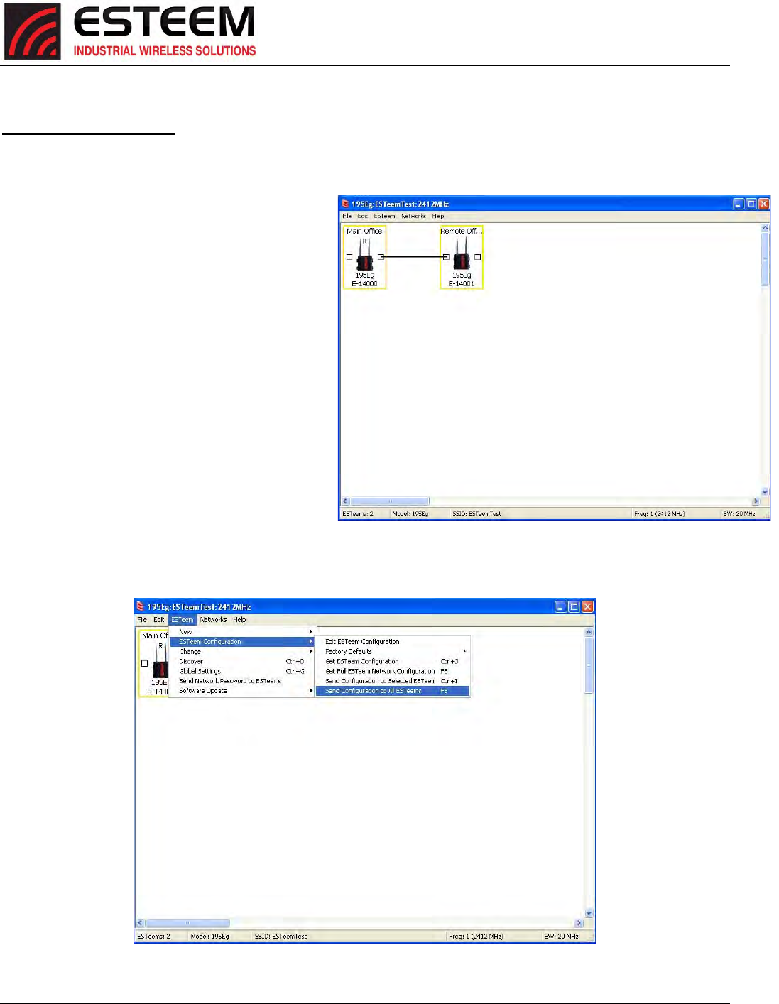
1. AddthetwoESTeemHorizonstothenetwork
usingtheaboveprocedure.OncebothESTeem
Horizonsareontheconfigurationpage,createa
wirelesslinkbyclinkingononeofthetwo
connectionboxesanddraggingalinetotheother
modem(Figure13).
5. VerifybothESTeemmodemsareconnectedto
thesameswitchasthecomputerrunningtheENC
Utilityandsendtheconfigurationtoboth
modemsatthesametimebyselecting
ESTeem>ESTeemConfiguration>Send
ConfigurationtoAllESTeems(Figure14).
6. OncetheENCUtilityhasdownloadedthe
configurationforbothESTeemHorizons,the
statusboxaroundtheESTeemswillchangefrom
yellowtoblue.Thisindicatesthatthe
configurationwascompletedsuccessfullyandthe
ESTeemHorizonsarereadytobeinstalledinthe
application.
Figure13:CreateWirelessLink
Figure14:SendConfigurationtoESTeem’s
CHAPTER3
EXAMPLEAPPLICATIONS
Revised: 27 Jun 16 3-10 ESTeem Horizon Series
EthernetBridgeModeExample2(Figure2)
PointtoPointwithRepeaterEthernetBridge
(3)ESTeemHorizon
SerialNumbers:
Z‐14000(MainOffice)
Z‐14001(RemoteOffice)
Z‐14002(Repeater)
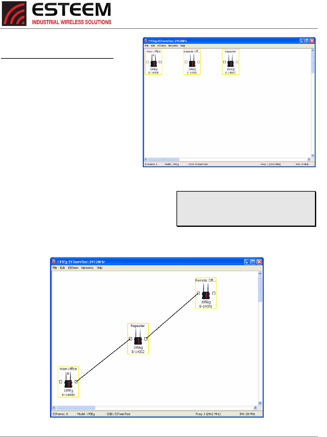
1.Usingtheaboveprocedure,enterthethree
ESTeemHorizonsintotheENCUtility.Your
layoutshouldappearlikeFigure14.
2. MovetheESTeemHorizoniconsonthescreen
tosimulatethelayoutofthediagram.Draw
connectionlinesbetweenthemodemstomake
thewirelesslinkinthesameorderasthe
networklayout(Figure15).
3. VerifyallESTeemmodemsareconnectedtothesameswitch
asthecomputerrunningtheENCUtilityandsendthe
configurationtobothmodemsatthesametimeby
selectingESTeem>ESTeemConfiguration>SendConfiguration
toAllESTeems.OncetheENCUtilityhasdownloadedthe
configurationforbothESTeemHorizon’s,thestatusbox
aroundtheESTeem‘swillchangefromyellowtoblue.Thisindicatesthattheconfigurationwascompletedsuccessfully
andtheESTeemHorizon’sarereadytobeinstalledintheapplication.
TechnicalTip:Althoughitdoesnotmatterwherethe
ESTeemiconsarelocatedonthescreen,putting
theminthesamelayoutastheapplicationmakesit
easiertovisuallyverifythenetworkconnections.
Figure14:Example2Modems
Figure15:Example2Layout
CHAPTER3
EXAMPLEAPPLICATIONS
Revised: 27 Jun 16 3-11 ESTeem Horizon Series
EthernetBridgeModeExample3(Figure3)
PointtoMultipointwithMeshRepeaterLinks
(6)ESTeemHorizon
SerialNumbers:
Z‐14000(MainOffice)
Z‐14001(RemoteOffice)
Z‐14002(Repeater)
Z‐14003(RemoteSite1)
Z‐14004(RemoteSite2)
Z‐14005(RemoteSite3)
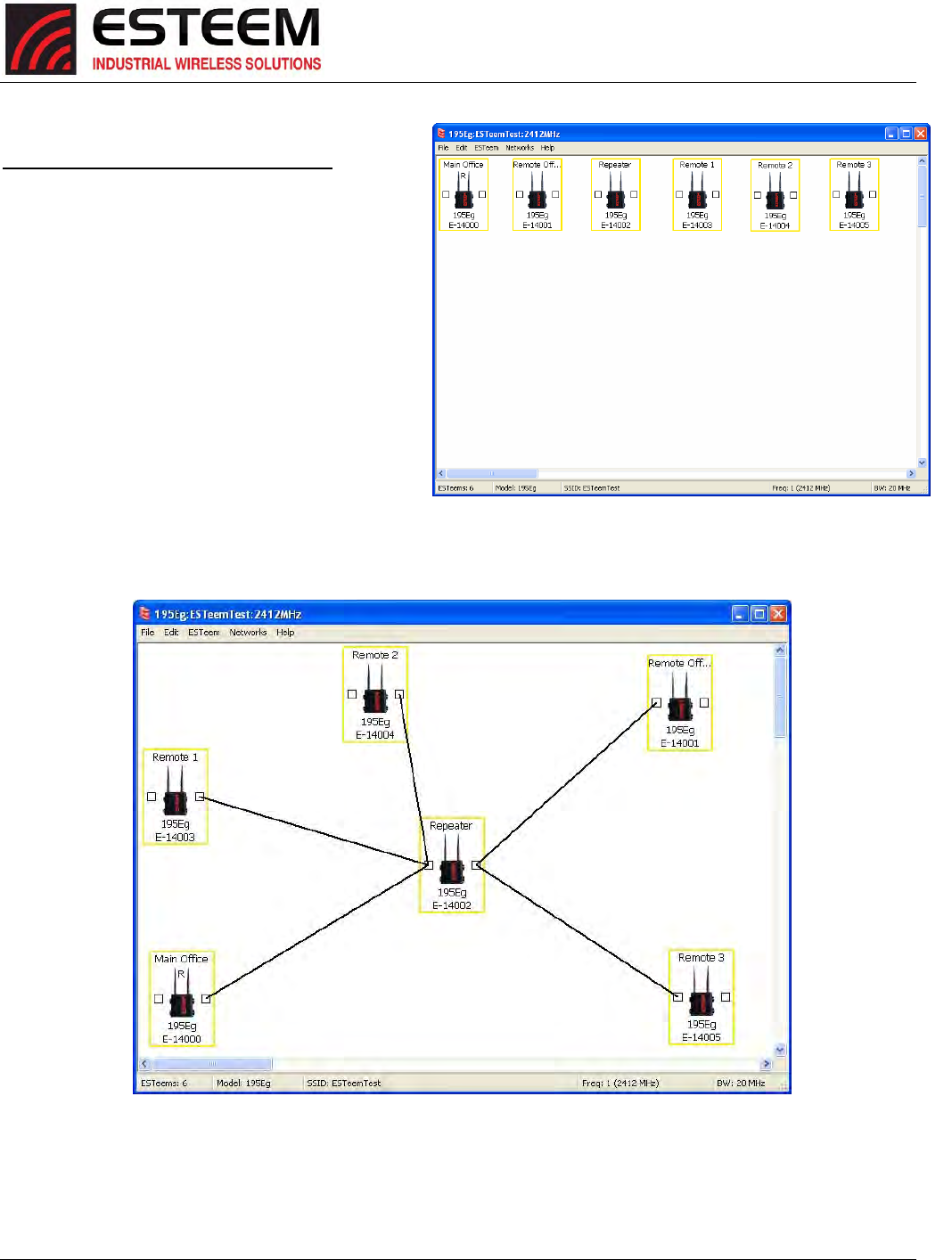
1. UsingtheaboveprocedureforaddingESTeem
Horizons,addthesixESTeemHorizonsforthis
exampleandrenamebylocation.Yourlayout
shouldappearlikeFigure16.
2. MovetheESTeemHorizoniconsonthescreento
simulatethelayoutofthediagram.Draw
connectionlinesbetweentheprimarywireless
linksmodemsinthesameorderasthenetworklayout(Figure17).
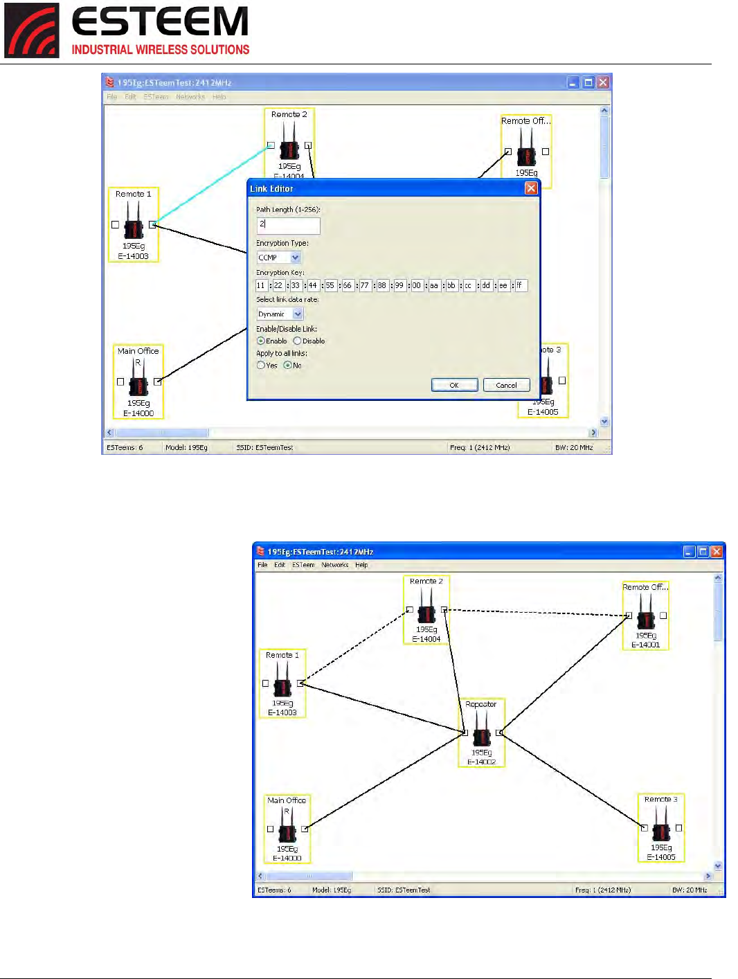
3. TocreatethebackuplinkbetweenRemote1andRemote2andtheotherbackuplinkfromRemote2totheRemoteOffice,
drawawirelessconnectionasyouwouldontheprimarylink.Double‐clickonthelinecreated.TheLinkEditorboxwillbe
displayed(Figure16).AnyPathLengthgreaterthan1willdisplayasadashedlineindicatingabackuplinkintherepeater
Figure16:Example3Modems
Figure15:Example2Layout
CHAPTER3
EXAMPLEAPPLICATIONS
Revised: 27 Jun 16 3-12 ESTeem Horizon Series
Meshconfiguration(Figure17).FordetailedinstructiononMeshnetworkconfiguration,refertoChapter7ofthisUser’s
Manual.
4. VerifyallESTeemmodemsare
connectedtothesameswitchas
thecomputerrunningtheENC
Utilityandsendtheconfiguration
toallmodemsatthesametimeby
selectingESTeem>ESTeem
Configuration>SendConfiguration
toAllESTeems.OncetheENC
Utilityhasdownloadedthe
configurationforbothESTeem
Horizon’s,thestatusboxaround
theESTeem‘swillchangefrom
yellowtoblue.Thisindicatesthat
theconfigurationwascompleted
successfullyandtheESTeem
Horizon’sarereadytobeinstalled
intheapplication.
Figure16:BackupLinkConfiguration
Figure17:MeshNetworkConfiguration
CHAPTER3
EXAMPLEAPPLICATIONS
Revised: 27 Jun 16 3-13 ESTeem Horizon Series
EthernetRouterModeExample(Figure4)
PointtoMultipointRouterMode
(4)ESTeemHorizon
SerialNumbers:
Z‐14000(RouteratNetwork)
Z‐14001(RemoteSite1)
Z‐14002(RemoteSite2)
Z‐14003(RemoteSite3)
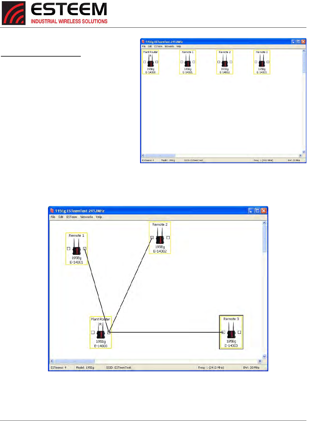
1. UsingtheaboveprocedureforaddingESTeem
Horizons,addthefourESTeemHorizonsforthis
exampleandrenamebylocation.Yourlayout
shouldappearlikeFigure18.
2. MovetheESTeemHorizoniconsonthescreento
simulatethelayoutofthediagram.Draw
connectionlinesbetweenthewirelesslinks
modemsinthesameorderasthenetworklayout
(Figure19).
Figure18:RouterModeExampleModems
Figure19:RouterExampleLayout
CHAPTER3
EXAMPLEAPPLICATIONS
Revised: 27 Jun 16 3-14 ESTeem Horizon Series
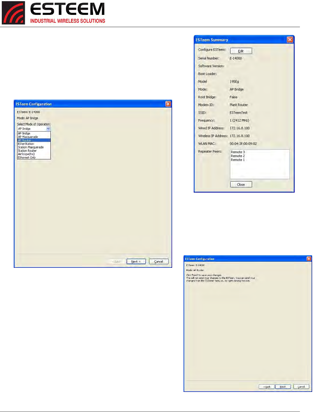
3. Bydefault,theENCUtilitysetsallESTeemmodemsinAPBridgemode.
TochangethePlantRouterESTeemtoAPRoutermode,double‐clickon
theicontobringuptheESTeemSummarywindowandpresstheEdit
button(Figure20).
4. ChangetheModeofOperationfromAPBridgetoAPRouter
(orMasqueradeifdesired)andpresstheNextbuttonatthebottomof
thewindow(Figure21).
5. ContinuethroughtheconfigurationscreenssettingtheAPRouter
addressingtomatchtheIPaddressrangesforyournetwork.Forhelp
withsettingtherouteraddressingpleaserefertoRouterAddress
Exampleslaterinthischapter.YouwillendonthescreeninFigure
22.PresstheFinishbuttontoreturntotheconfigurationpage.
6. VerifyallESTeemmodemsareconnectedtothesameswitchasthe
computerrunningtheENCUtilityandsendtheconfigurationtoall
modemsatthesametimebyselectingESTeem>ESTeem
Configuration>SendConfigurationtoAllESTeem’s.OncetheENC
UtilityhasdownloadedtheconfigurationforbothESTeemHorizons,
thestatusboxaroundtheESTeem’swillchangefromyellowtoblue.
Thisindicatesthattheconfigurationwascompletedsuccessfullyand
theESTeemHorizonsarereadytobeinstalledintheapplication.
Figure21:APRouterConfiguration
Figure20:ESTeemSummaryPage
Figure22:ESTeemSummaryPage
CHAPTER3
EXAMPLEAPPLICATIONS
Revised: 27 Jun 16 3-15 ESTeem Horizon Series
MobileClientModeExample(Figure5)
EtherStation,StationRouterandStationMasqueradeModes
(3)ESTeemHorizon
SerialNumbers:
Z‐14000(EtherStation)
Z‐14001(StationRouter)
Z‐14002(StationMasquerade)
SettingtheESTeemforMobileClient(station)modewiththeENCUtilityisdifferentthanthe
Bridge/RouterorAccessPoint(AP)modes.ESTeemmodemsconfiguredinasaMobileClientwill
notlinkwithaspecificfixedmodem;butwillroambetweenany802.11AccessPointwiththe
correctNetworkName(SSID)andEncryption.TheESTeemconfiguredasaclientisalsonotseton
aspecificoperatingfrequency(channel)butwillscanallchannelslookingfortheAP.Usethe
followingproceduretoconfigureanESTeemHorizoninoneofthethreemobileclientmodes:
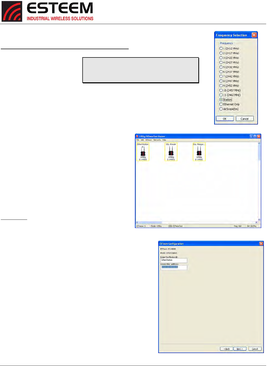
1. StartinganewnetworkofESTeemHorizonsinMobile
ClientmodeisthesameasanyoftheBridgemodes
exceptwhenyouareaskedforthefrequency(channel)
ofoperation,select“Station”(Figure23).
2. AddthethreemobileclientmodemstotheENCUtility
configurationpageasinstructedaboveandsetthe
ModemIDtomatchthethreemodesofoperation.
YourconfigurationwillappearasinFigure24.
EtherStation
3. Bydefault,theENCUtilitysetsallstationmodeESTeem
modemstoEtherStationmode.Theonlyadjustment
necessarytotheEtherStationmodeminourexampleis
toentertheconnectedEthernetdevice’sMACaddress.The
ESTeemHorizonwill“clone”theEthernetMACaddressofthe
connectedEthernetdevice.ToconfiguretheEtherStation
modem,double‐clickontheicontobringuptheESTeemSummary
windowandpresstheEditbutton(Figure20).
4. EtherStationmodeshouldbeselectedintheModeofOperation.
PresstheNextbuttonatthebottomofthewindowtocontinue.
EntertheconnectedEthernetdevice’sMACaddressinthe“Device
MACAddress”box(Figure25)andpresstheNextbuttonatthe
bottomofthewindowtocontinue.
5. Verifytheencryptionsettingsarecorrectforthe802.11AP
networkinwhichtheEtherStationmodemwillbeworkingand
presstheFinishbuttontoreturntotheconfigurationpage.
TechnicalTip:TheESTeemHorizon’sinMobileClient
modesdonothaveaspecificfrequencyofoperation
ascanbeseeninFigure24.
Figure23:Station
Figure24:StationModeExampleModems
Figure25:MACAddressEntry
CHAPTER3
EXAMPLEAPPLICATIONS
Revised: 27 Jun 16 3-16 ESTeem Horizon Series
StationRouterandStationMasquerade
6. Toconfigurethetwoothermodems,double‐clickontheiricons
tobringuptheESTeemSummarywindowandpresstheEdit
button(Figure20).
7. SelectStationRouterforZ‐14001andStationMasqueradefor
Z‐14002intheModeofOperation(Figure26).PresstheNext
buttonatthebottomofthewindowtocontinue.
8. ContinuethroughtheconfigurationscreenssettingtheStation
Router/MasqueradeaddressingtomatchtheIPaddressranges
foryournetwork.Forhelpwithsettingtherouteraddressing
pleaserefertoRouterAddressExampleslaterinthischapter.
9. Verifytheencryptionsettingsarecorrectforthe802.11AP
networkinwhichtheEtherStationmodemwillbeworkingand
presstheFinishbuttontoreturntotheconfigurationpage.
10. VerifyallESTeemmodemsareconnectedtothesameswitchas
thecomputerrunningtheENCUtilityandsendthe
configurationtoallmodemsatthesametimebyselecting
ESTeem>ESTeemConfiguration>SendConfigurationtoAll
ESTeems.OncetheENCUtilityhasdownloadedtheconfigurationforbothESTeemHorizons,thestatusboxaroundthe
ESTeemswillchangefromyellowtoblue.ThisindicatesthattheconfigurationwascompletedsuccessfullyandtheESTeem
Horizonsarereadytobeinstalledintheapplication.
802.11AccessPointModes(Figures6‐8)
AccessPointBridge,RouterorMasqueradeModes
ConfiguringtheESTeemHorizonasanAccessPointfor
802.11clients(asseenFigures6‐8)isexactlythesameas
configurationforAPBridge,APRouterandAP
Masqueradeasshownabove.Theonlydifferencebeing
thatawirelesslinkisonlyaddedbetweenESTeem
Horizonswhereawirelessconnectionisnecessary.In
figures6and7therewouldbenowirelesslinklistedin
theENCUtility.Infigure8,theconfigurationwouldbe
exactlyasshowninFigure2withtheadditionofthe
mobileclientsinthenetwork.
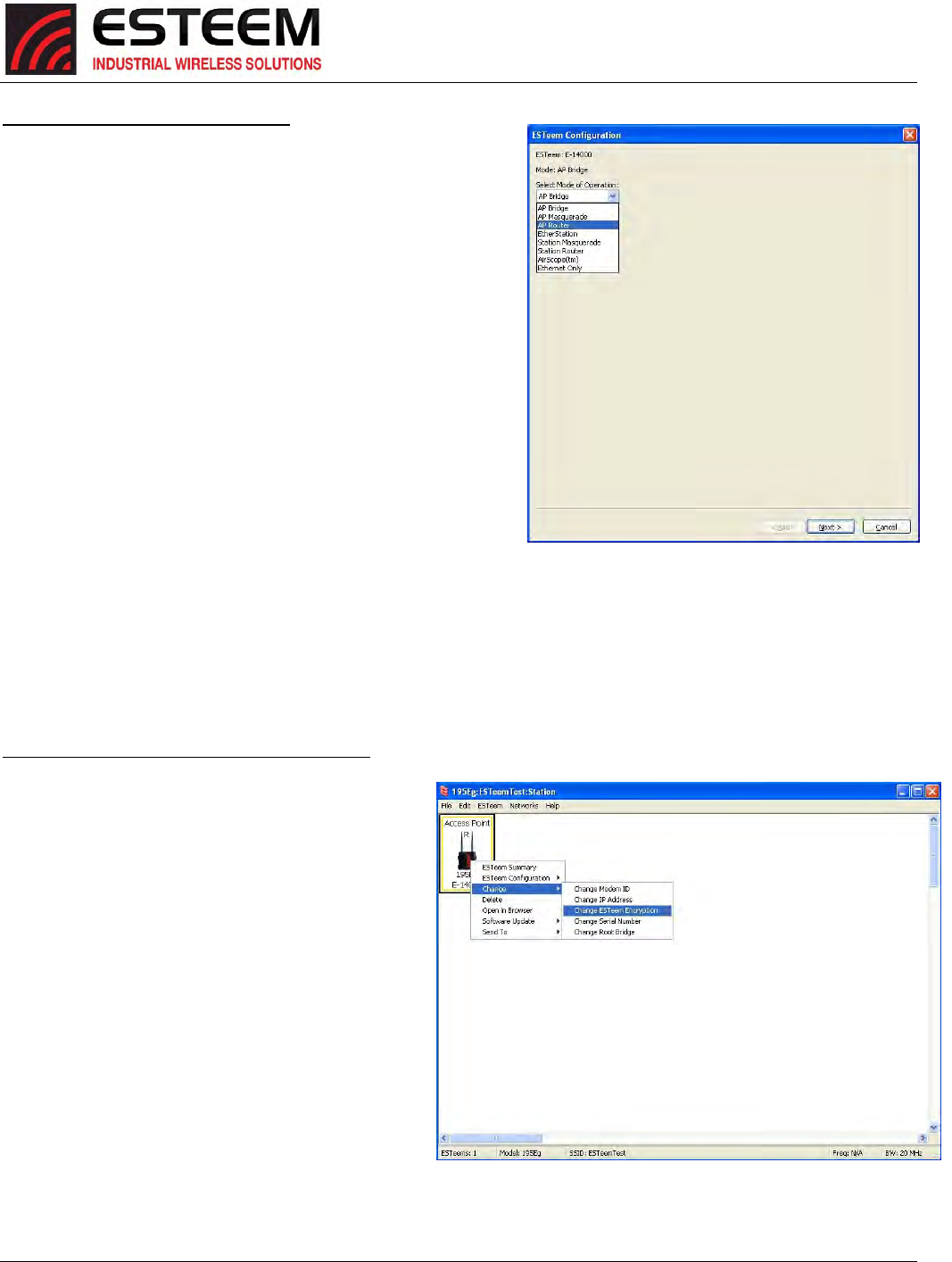
The802.11clientswillusetheSSIDconfiguredduringthe
setupofthenetworkwiththeENCUtility.The
encryptionwillbesetatthefactorydefaultsettingsfor
clients(WPAPSK).Toadjusttheencryptiontype,right‐
mouseclickontheESTeemiconandselect
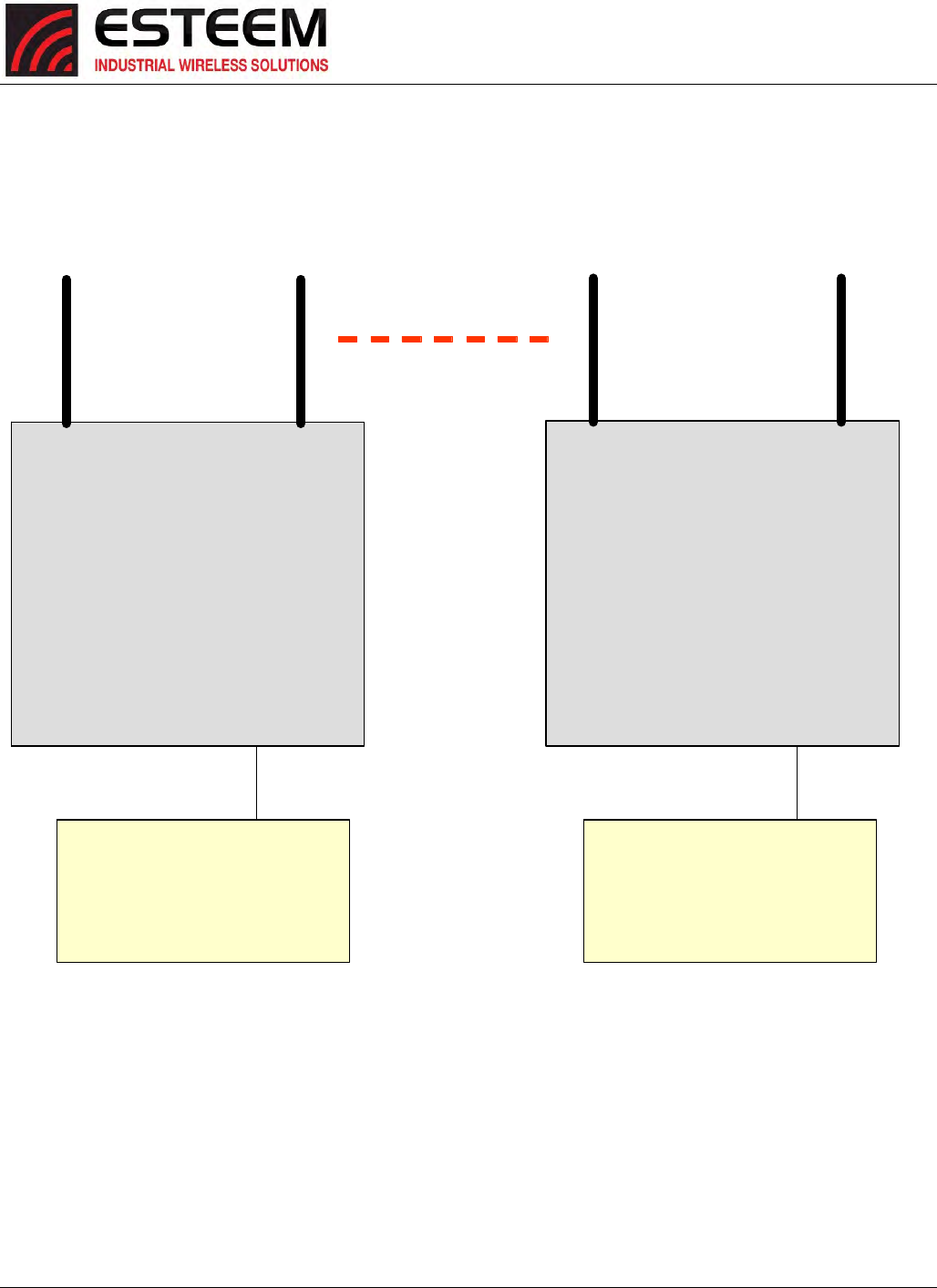
Change>ChangeESTeemEncryption(Figure27).
Figure26:ModeofOperationSelection
Figure27:EncryptionConfiguration
CHAPTER3
EXAMPLEAPPLICATIONS
Revised: 27 Jun 16 3-17 ESTeem Horizon Series
ROUTERADDRESSINGEXAMPLES
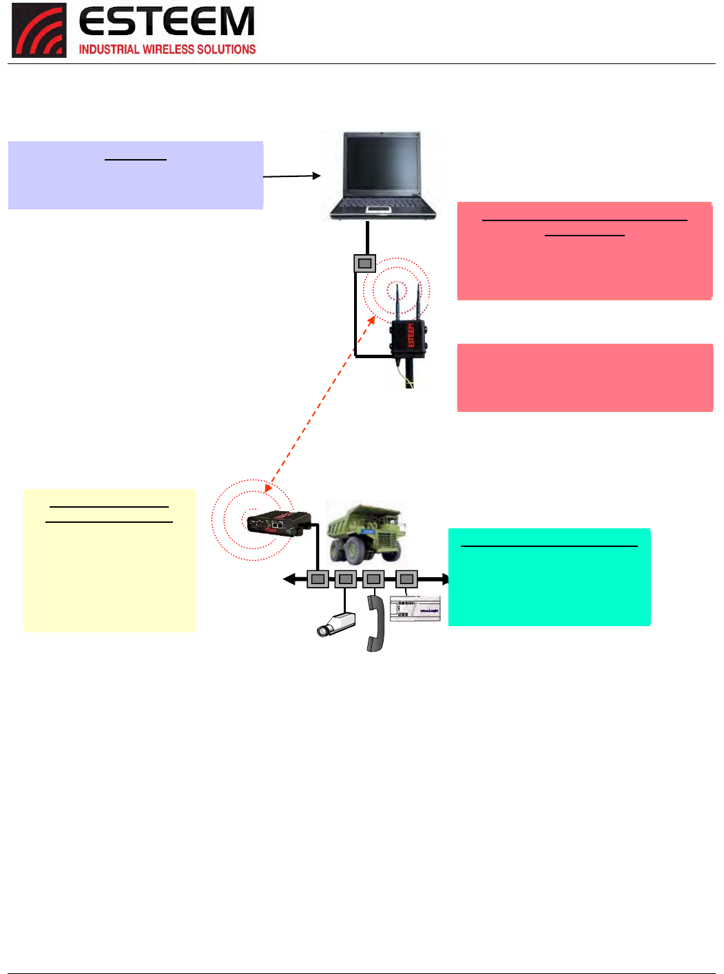
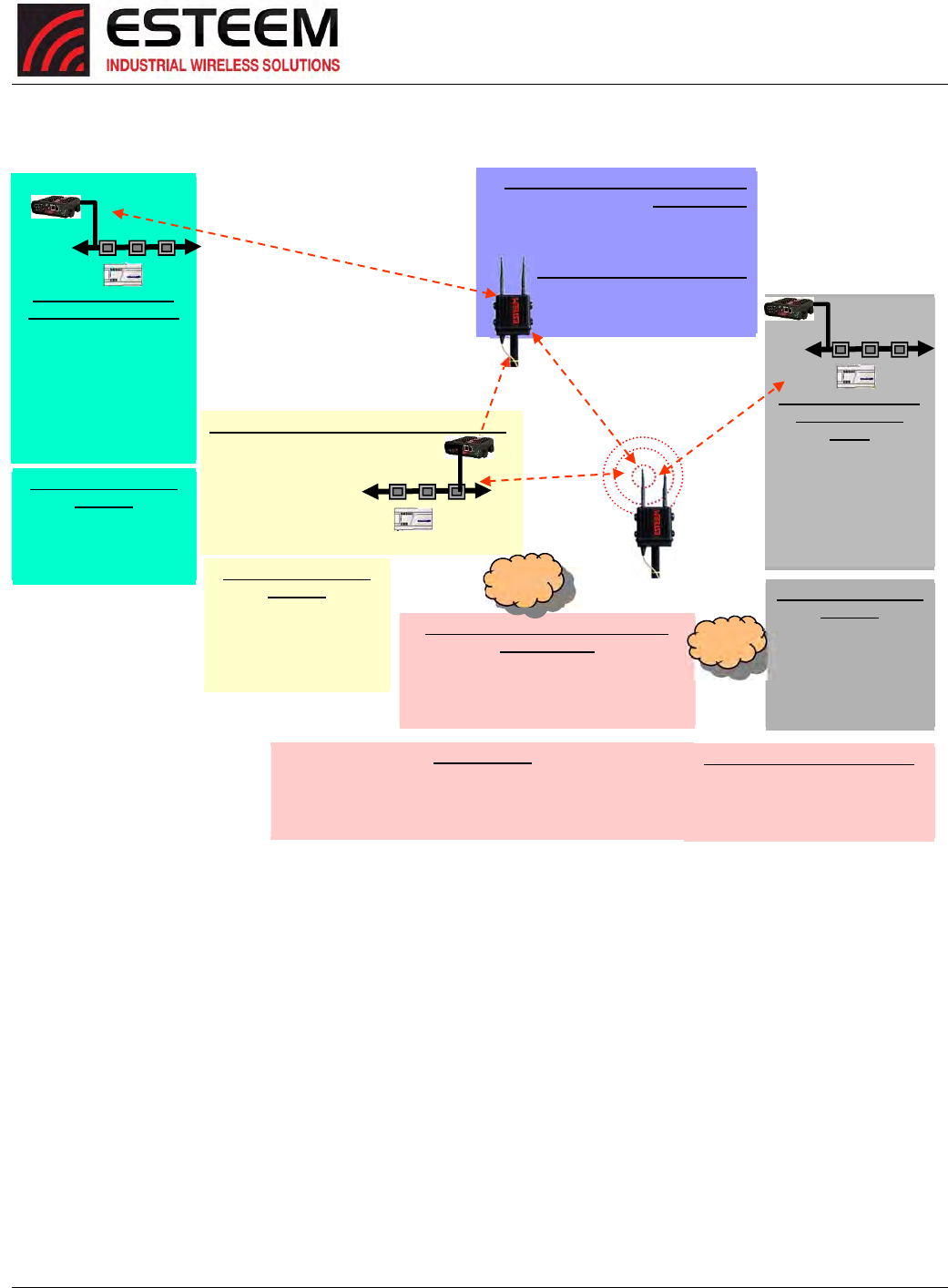
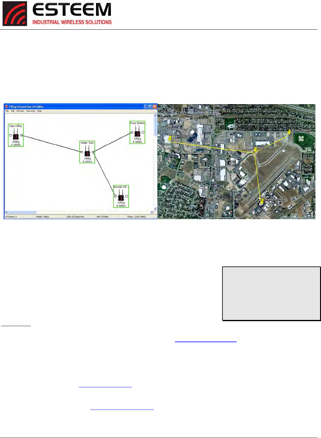
ThefollowingareexamplesoftheIPaddressingandsubnetsrequiredfortheESTeemRoutermodes.
PointtoPointAccessPointRoutertoStationRouter
AP Router
Wireless IP Address: 172.16.1.6
Netmask: 255.255.0.0
Default Route: 172.17.1.6
Ethernet IP Address: 172.17.1.6
Netmask: 255.255.0.0
Static Route: 172.20.0.0
255.255.0.0
gateway: 172.16.2.22
Station Router
Wireless IP Address: 172.16.2.22
Netmask: 255.255.0.0
Default Route: 172.16.1.6
Ethernet IP Address: 172.20.2.22
Netmask: 255.255.0.0
Device
IP address: 172.17.X.X
Netmask: 255.255.0.0
Default gateway 172.17.1.6
Device
IP address: 172.20.X.X
Netmask: 255.255.0.0
Default gateway 172.20.2.22
Figure28:APRouterAddressingExample
CHAPTER3
EXAMPLEAPPLICATIONS
Revised: 27 Jun 16 3-18 ESTeem Horizon Series
Stand‐AloneAccessPointRouterandSingleStationRouter
Figure29:StationRouterAddressingExample
Static Routes
Routes for 172.18.0.0 network use
gateway 172.16.2.20
Note: Wireless Networks and
Station Devices Must Be on
Separate Subnets
ESTeem Horizon in Access Point
Router Mode
Ethernet IP Address = 172.17.1.6
Wireless IP Address 172.16.1.6
Netmask = 255.255.0.0
Default Route = 172.17.1.6
ESTeem Horizon in
Station Router Mode
Netmask 255.255.0.0
Wireless IP Address
172.16.2.20
Ethernet IP Address
172.18.2.20
Gateway(Route)
172.16.1.6
Connected Ethernet Devices
IP Address 172.18.X.X
Netmask 255.255.0.0
Gateway (Route) =
172.18.2.20
Computer
IP Address = 172.17.1.1
Netmask = 255.255.0.0
Default Route = 172.17.1.6
CHAPTER3
EXAMPLEAPPLICATIONS
Revised: 27 Jun 16 3-19 ESTeem Horizon Series
Stand‐AloneAccessPointRouterwithMultipleStationRouters
Figure30:CompleteRouterAddressingExample
ESTeem Horizon in Access Point
Bridge Mode
Bridge IP Address = 172.16.1.7
Netmask = 255.255.0.0
Default Route = 172.16.1.6
Connected Ethernet Devices
IP Address 172.16.X.X
Netmask 255.255.0.0
Gateway (Route) = 172.16.1.6
ESTeem Horizon in
Station Router
Mode
Netmask 255.255.0.0
Wireless IP Address
172.16.2.22
Ethernet IP Address
172.20.2.20
Gateway(Route)
172.16.1.6
ESTeem Horizon in Station Router Mode
Netmask 255.255.0.0
Wireless IP Address 172.16.2.20
Ethernet IP Address
172.18.2.20
Gateway(Route) 172.16.1.6
Static Routes
Routes for 172.18.0.0 network use gateway 172.16.2.20
Routes for 172.19.0.0 network use gateway 172.16.2.21
Routes for 172.20.0.0 network use gateway 172.16.2.22
Routes for 172.16.0.0 network use gateway 172.16.1.6
Note: Wireless Networks
and Station Devices
Must Be on Separate
Subnets
ESTeem Horizon in Access Point
Router Mode
Ethernet IP Address = 172.17.1.6
Wireless IP Address 172.16.1.6
Netmask = 255.255.0.0
Default Route = 172.17.1.6
ESTeem Horizon in
Station Router Mode
Netmask 255.255.0.0
Wireless IP Address
172.16.2.21
Ethernet IP Address
172.19.2.20
Gateway(Route)
172.16.1.6
Connected Ethernet
Devices
IP Address 172.18.X.X
Netmask 255.255.0.0
Gateway (Route) =
172.18.2.20
Connected Ethernet Devices
IP Address 172.17.X.X
Netmask 255.255.0.0
Gateway (Route) = 172.17.1.6
Connected Ethernet
Devices
IP Address 172.19.X.X
Netmask 255.255.0.0
Gateway (Route) =
172.19.2.20
Connected Ethernet
Devices
IP Address
172.20.X.X
Netmask
255.255.0.0
Gateway (Route) =
172.20.2.20
Blockage
Blockage
CHAPTER4
UTILITIES&FEATURES
Revised: 25 Jan 17 4-1 ESTeem Horizon Series
ESTeemNetworkConfigurationUtility(ENC)
TheESTeemNetworkConfiguration(ENC)Utilityisasoftwareprogramdesignedtogreatlysimplifytheconfigurationofyour
HorizonwirelessEthernetnetwork.TheENCUtilitywillallowgraphical,point‐and‐clickconfigurationofyournetworkrouting,
thenconfigureeachESTeemwirelessmodemforthenetworkasdesigned(Figure1).TheENCUtilitywilleliminatetheneedto
programorupdateeachESTeemwirelessmodemindividually.TheENCUtilitycansendallwirelessmodemconfigurationchanges
simultaneouslytoaneworexistingnetwork.
TheENCUtilitywillbeusedforallwirelessnetworkprogramminginthisUser’sManual.Fordetailedinstructionsontheuseof
theESTeemNetworkConfiguration(ENC)UtilitypleaserefertheENCUtilityUser’sGuideavailableontheESTeemResourceCDor
intheapplicationitself.
ESTeemDiscoveryUtility
TheESTeemDiscoveryUtilitywillallowyoutoconfiguretheIPaddressontheHorizon
radiotomatchyournetworkregardlessofitscurrentIPsubnet.Thisutilitywillalsoallow
youtoupdatethesoftwareintheHorizonandopenthewebconfigurationforthat
wirelessmodem.
Installation
TheDiscoveryUtilitycanbedownloadedfromtheESTeemwebsite(http://www.esteem.com)orisavailableontheSoftware
ResourcemediathatwasshippedwiththeHorizonradios.
1. TheDiscoveryUtilityisaJava™basedapplicationcompatiblewithanycomputeroperatingsystem(Window,Linux,etc).The
applicationrequirestwo(2)additionalsupportfilestooperate:
Java–Downloadablefromhttp://www.java.com.Theversionrequiredwillbebaseduponyouroperatingsystem.
Note:TheinstallationandupdatesfromJavamaytryandinstalladditionalwebbrowsertoolbars.Unchecktheoptional
installationiftheyarenotdesired.
WinPcap–Downloadablefromhttp://www.winpcap.org/.Theversionrequiredwillbebaseduponyouroperatingsystem.
Figure1:ESTeemNetworkConfigurationUtility
TechnicalTip:Ifyourcomputeris
configuredforDHCPandnot
attachedtothenetwork,youwill
needtoassignastaticIPaddress
toprogramtheHorizon.
CHAPTER4
UTILITIES&FEATURES
Revised: 25 Jan 17 4-2 ESTeem Horizon Series
2. Onceboththeaboveprogramshavebeeninstalled,savetheESTeem.exefiletoanylocationonyourcomputersuchasthe
Desktop.DoubleclicktheESTeem.exeprogramandFigure2willbedisplayed.
3. ConnecttheHorizonmodemtoyourcomputereitherdirectlytotheEthernetcardorthroughaSwitchusingaCAT‐5e
Ethernetcable.TheEthernetportsupportsAuto‐Negotiation,soeitherapatchcableorcrossovercablewillwork.Pressthe
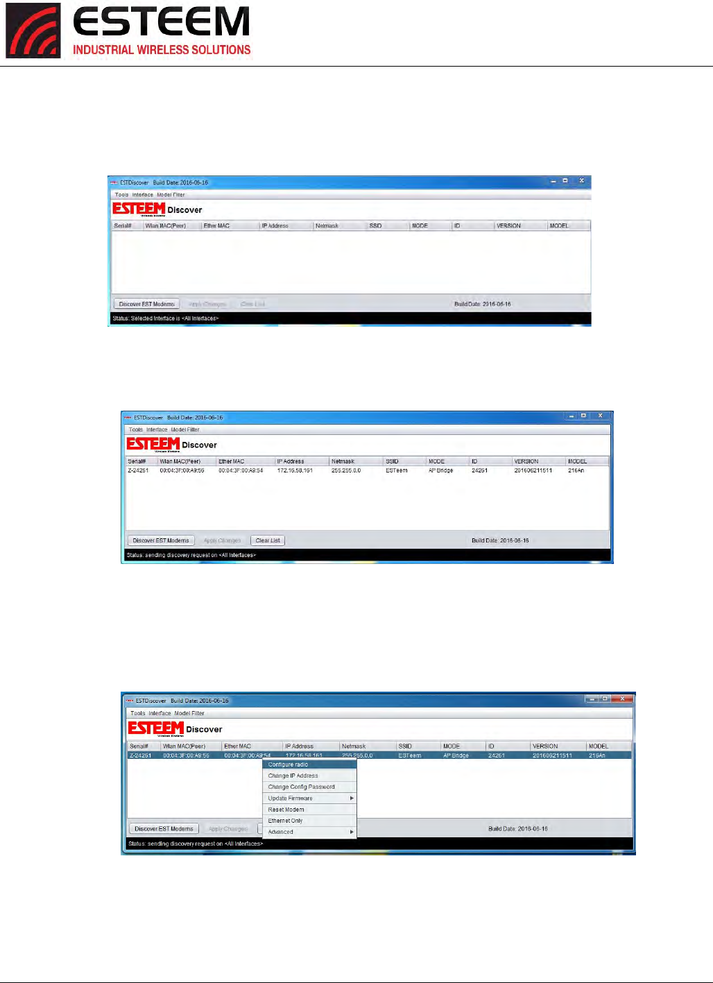
DiscoverESTModemsbutton.
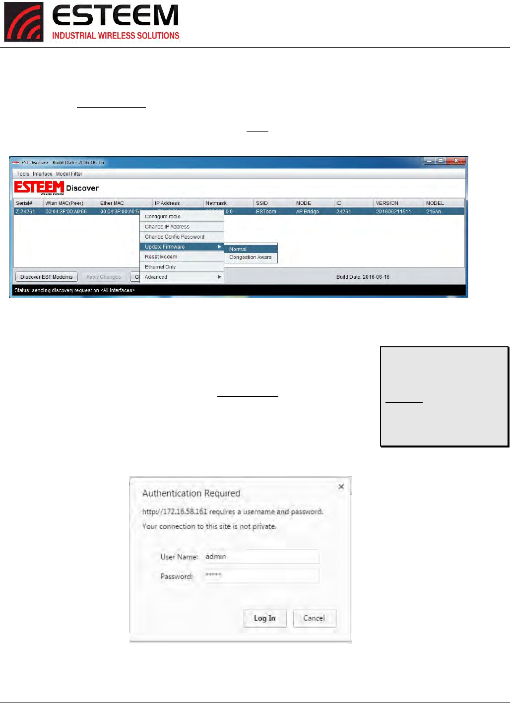
4. TheESTeemHorizonwillbedisplayed(Figure3).IftheESTeemHorizonisnotonthesameIPsubnetasthecomputer,double
clickontheIP,NetmaskorGatewayandmakethenecessarychanges.PresstheApplyChangesbuttonwhencomplete.
5. IfchangesweremadetotheIPaddress,youwillneedtopresstheDiscoverESTModemsbuttonagaintoshowthechanges.
Right‐mouseclickontheHorizonandselectConfigureRadiobuttontobeginprogramming.
Figure2:ESTeemDiscoveryUtility
Figure3:ESTeemDiscoveryUtility
Figure4:OpeningRadioConfigurationSoftware
CHAPTER4
UTILITIES&FEATURES
Revised: 25 Jan 17 4-3 ESTeem Horizon Series
FirmwareUpdates
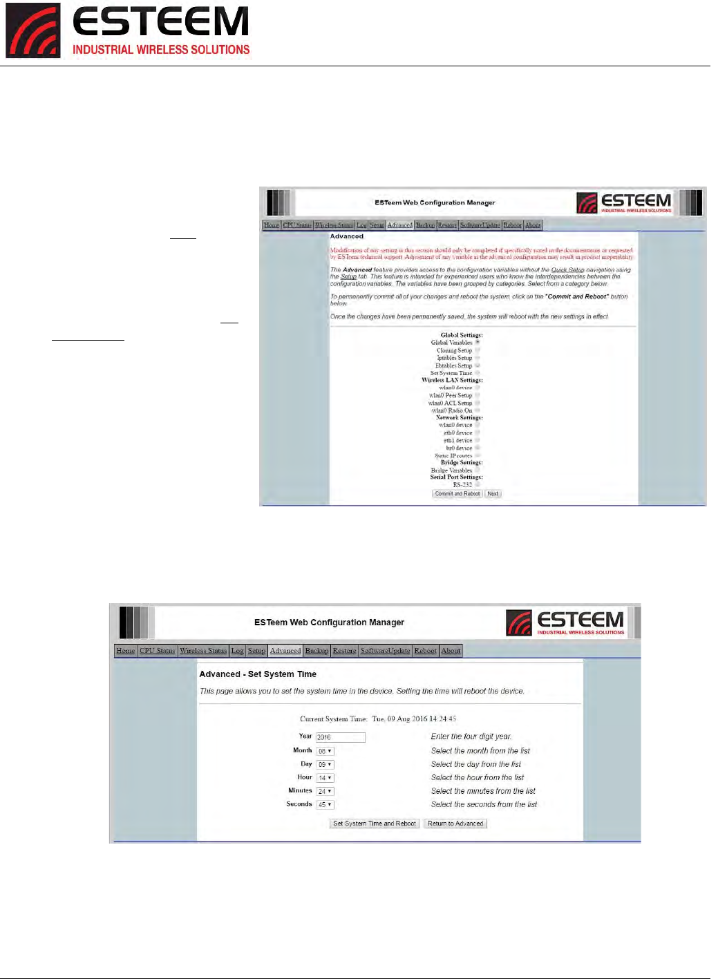
ToupdatefirmwareonanyESTeemHorizonthatisshownontheDiscoveryprogram,“right‐mouse”clickontheHorizon’sMAC
addressandselectUpdateFirmwarefromthemenu(Figure5).Therearetwofirmwareupdateoptionsavailable,“Normal”and
“CongestionAware”.SelectNormalformostupdatesanduseCongestionAwarewhensendingtheupdateoverthewirelesslink
onabusynetwork.Onceyoulocatetheupdatefile,selecttheOpenbuttonandtheHorizonwillupdate,validateandthenreboot
withtheupdatedoperatingsystem.
OpeningWebBrowser
ToquicklyopenawebbrowserpagetotheIPaddressprogrammedintheHorizon,“right‐
mouse”clickontheHorizon’sMACaddressandselectConfigureradiofromthemenu(Figure
5).IfyourcomputerisconfiguredforthesameIPsubnetattheESTeemHorizonwireless
modem,youwillbeaskedtosigninwiththeUsernameandPassword(Figure6).Youcannow
beginprogrammingtheHorizonforyourapplication.
Figure5:DiscoveryFeaturesMenu
TechnicalTip:Thedefault
UsernameandPasswordis
“admin”(alllowercase).
Example
Username:admin
Password:admin
Figure6:ESTeemWebPageLog‐onScreen
CHAPTER4
UTILITIES&FEATURES
Revised: 25 Jan 17 4-4 ESTeem Horizon Series
SETTINGLOCALTIME
TheESTeemHorizonwillbeshippedfromthefactorywiththeinternalreal‐timeclocksettoPacificTime.Tochangetheclock
settingstothelocaltimeforaccuratelogfileentries:
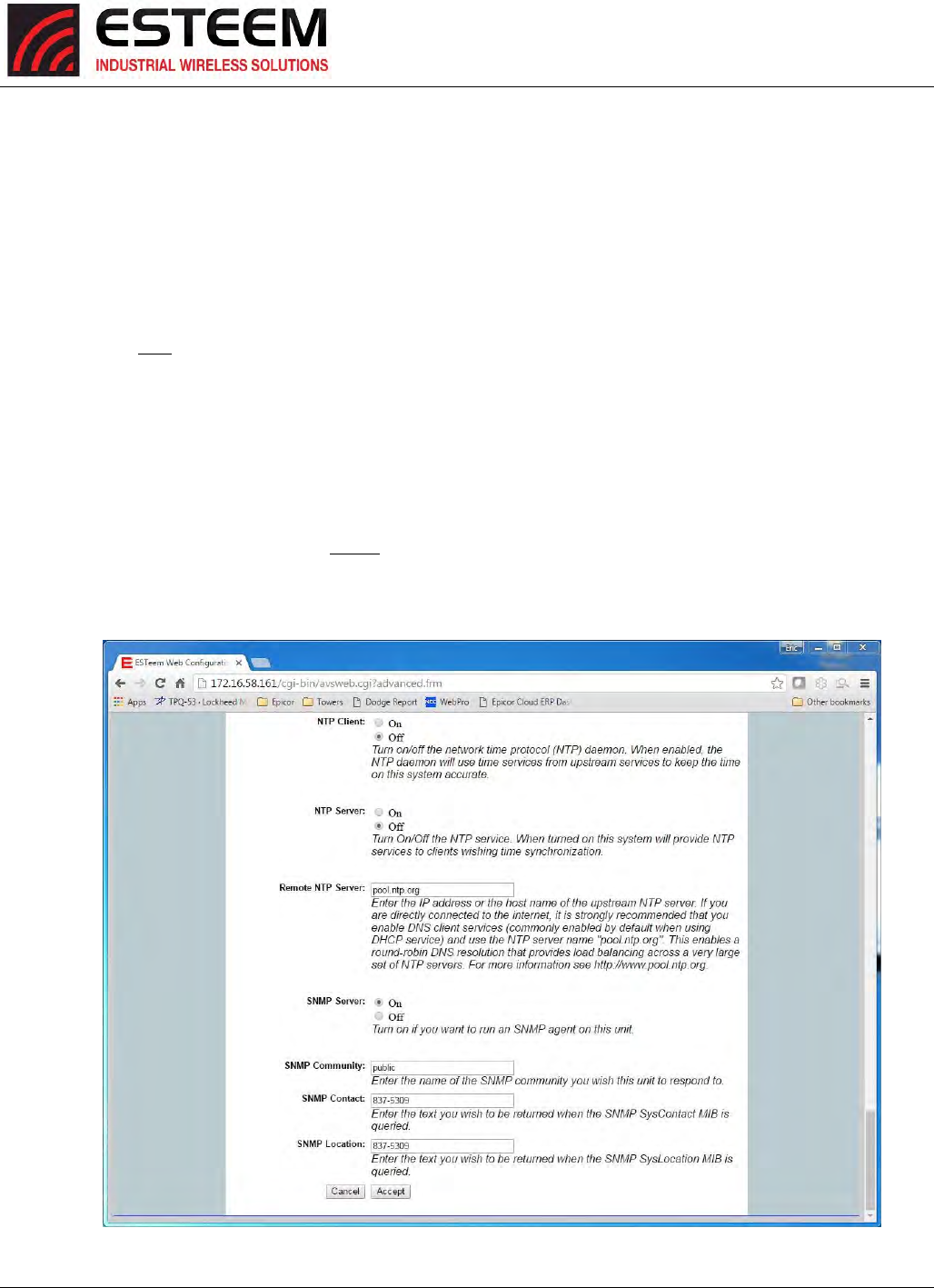
2. SelectAdvancedfromthetop
Menu,selectGlobalSettings>Set
SystemTime(Figure7)fromthe
menuandpresstheNextbutton
tocontinue.
3. Selectthecorrectdateandtime
fromthedrop‐downmenus
(Figure8)andpresstheSet
SystemTimebuttontosavethe
timetotherealtimeclock.
Figure7:AdvancedFeaturesScreen
Figure8:AdvancedFeaturesScreen
CHAPTER4
UTILITIES&FEATURES
Revised: 25 Jan 17 4-5 ESTeem Horizon Series
CONFIGURINGTIMESERVER
EnablingNTPtimesynchronizationservicesontheHorizonwillallowusageoftimeservicesfromupstreamservicestokeepthe
timeonthesystemaccurate.
Toallowtimesynchronization,theHorizonmustbeconfiguredwiththeNTPDaemonenabledandtheappropriateIPaddressof
theupstreamnetworkNTPserver.
1. SelectAdvancedfromthemenuitemsandGlobalVariables(Figure7).
2. PresstheNextbuttonandFigure9willbedisplayed.AtthebottomofthepagearetheNTPserverconfigurations.
3. TheNTPdaemonisenabledbyselectingONforNTPClient(Figure9).Whenenabled,theNTPdaemonwillusetime
servicesfromupstreamservicestokeepthetimeonthissystemaccurate.
4. Next,theNTPServershouldbeconfiguredto“On,”ifyouwanttoallowthesystemtoprovideNTPserviceforclients
wishingtimesynchronization(Figure9).
5. ThefinalstepinconfiguringNTPservicesistoentertheIPaddressorthehostnameoftheupstreamNTPserver.Once
configurationiscomplete,presstheAcceptbutton.
6. Tocompletetheconfiguration,select“CommitandReboot.”TheHorizonwillnowcommittheconfigurationchanges
andreboot.
Figure9:NTPSettings

CHAPTER4
UTILITIES&FEATURES
Revised: 25 Jan 17 4-6 ESTeem Horizon Series
VLANOPERATION
VirtualLAN(VLAN)systemsarerapidlybecomingthedesiredconfigurationonlargerEthernetnetworks.TheESTeemHorizon
softwarewillallowtheEthernetmodemstotransparentlypasstheVLANpacketsforthesenetworks.TheHorizoncurrentlycan
notbeusedasaVLANswitch,butwillpassVLANtaggedEthernetpacketsthroughthewirelessbridge.
IGMPSNOOPING
InternetGroupManagementProtocol(IGMP)SnoopingallowstheESTeemHorizontooperatemoreefficientlyinnetworkswith
highMulticast(UDP,etc.)traffic.IGMPSnoopingwilldefinethedestinationfortheMulticasttrafficandsendthedatatothe
correctwirelessEthernetmodem,nottheentirenetwork.ThislimitingofMulticasttraffictospecificdestinationsgreatlyincreases
theoverallnetworkefficiency.
TheproblemwithusingmulticasttrafficoverawirelessconnectionisthatmulticastpacketsdonotrequireanAcknowledgeon
theprotocollayer.IfthewirelessnetworkmissesadatapacketontheRFnetwork,thatmulticastdatapacketislost.
TheoryofOperation
TherearetwotypesofEthernetpacketsonanetwork,unicastandmulticast.Unicastisintendedforexactlyonerecipient(and
ignoredbyallothers).Multicastisintendedtobereceivedbymultiplerecipients.Interestedpartiescanlistenforparticular
multicastpackets,butmostnodesignoreit.Inanycase,thenetworkmediumisstillutilizednomatterhowmanynodesare
listening.Broadcastpacketsareaspecialtypeofmulticasttrafficwhichallnodesalwaysreceive.Theseareparticularlyusefulfor
globalannouncements(Hey,I'mAlice!)andqueries(Hey,I'mAliceandI'mlookingforBob!).Morerelevantly,itishowhostson
anetworkfindouteachother'saddresses,andareabsolutelycrucialtotheproperfunctioningofanetwork.
Asthenetworkgrowsphysically,itencounterssomegrowingpains.Thefirstismorephysical,relatingtothecablinglimitations.
Bridgessolvethisproblembyjoiningtwophysicalnetworkstogethersotheyappeartobeasinglelargenetwork.Throughuseof
bridges,anetworkcanscaletohundredsoreventhousandsofhosts.Thereisadownside,however.Wellbeforethephysical
limitationsofbridginghit,youstarttorunintoefficiencyproblems,asalltraffichastotraveleverywhereonthenetwork.Theraw
carryingcapacityofthissharedmedium,oftenreferredtoasbandwidth,isthesecondscalingproblem.
Smartbridges,orswitches,helpalleviatethebandwidthproblembyonlypassingtrafficacrossthebridgeifthedestinationhost
wasontheotherside.Thisgreatlyincreasesthecapacityandefficiencyofthenetworkbyallowingtwopairsofhosts
communicatingsimultaneouslyoneachsideoftheswitchedbridge.Onlywhenthepacketneedstogototheothersideisboth
mediumsutilizedsimultaneouslyforthesamepacket.
Unfortunately,broadcastandmulticasttrafficbyitsverynaturemustalwaysberelayedacrossthebridge.Whilethenumberof
networknodesmaygrowlinearly,themulticasttraffictendstogrowexponentially.Thisisn'tgenerallyaproblemforwired
networks,astheyhaveaconsiderableamountofbandwidthtospare,butwirelessnetworkshave,atbest,anorderofmagnitude
lessbandwidthtobeginwith.Ifawirelessnetworkisbridgedwithawirednetwork,whiletheabsolutenumbersarethesame,a
muchhigherproportionofthewirelessnetwork’savailablebandwidthisusedupbymulticasttraffic.Thiseffectisfurther
magnifiedifmultiplewirelessrepeatersareinuse.
Thepreferredwayofdealingwithexcessmulticasttrafficistoputthewirelessnetworkonadifferentsub‐network(subnet)and
usearoutertojoinittothewirednetwork.Thisensuresthatonlyunicasttrafficintendedforthewirelessnetworkcrossesover,
asmulticastandbroadcasttrafficstayswithinitslocalsubnet.Normallythisisfine,buttherearetimeswhereyouneedmulticast
traffictospansubnets.ForIPtraffic,thiscanbeobviatedbyusingamulticast‐capablerouter,butforlegacymulticastprotocols
thatwerenotdesignedtoberouted,anothersolutionmustbefound.
CHAPTER4
UTILITIES&FEATURES
Revised: 25 Jan 17 4-7 ESTeem Horizon Series
TherearetwoprimarytypesofcommunicationnetworksusedinwirelessEthernetsystems;fixedpointscommunicatingtoeach
otherthroughanEthernetBridgeandmobiledevicescommunicatingtothesefixedpoints.ThefixedpointEthernetbridge
communicationintheHorizonisthroughRepeaterPeerlinks,whilethemobilecommunicationisfromtheClientmodes
(EtherStation,StationRouterandStationMasquerade)totheAccessPoints(FixedLocations)inthenetwork.Eachofthese
networkshandlesMulticasttrafficdifferentlyasexplainedbelow.
EthernetBridgeMode(withPeers)
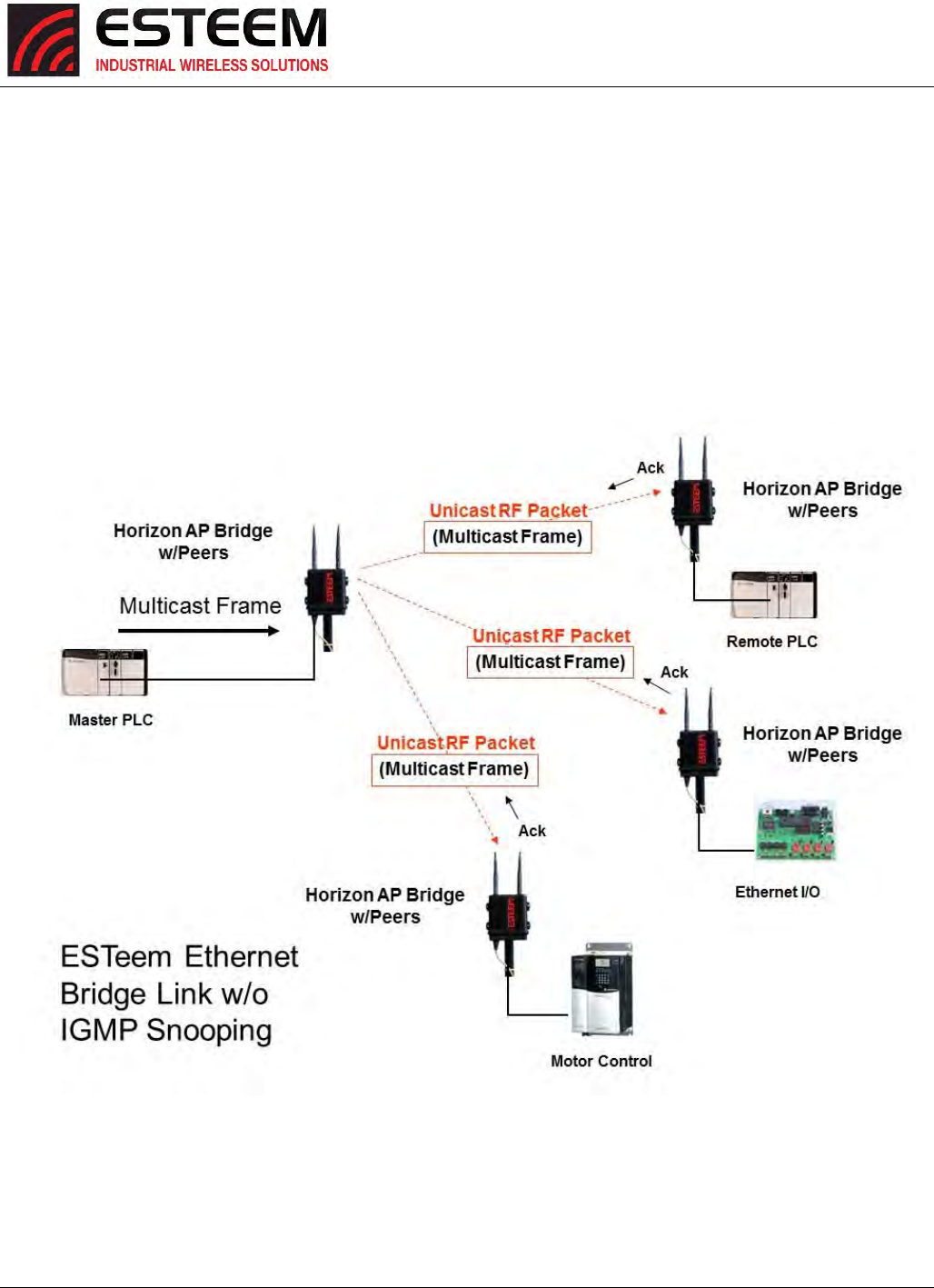
WhentheESTeemHorizonisconfiguredasapeer,allmulticasttrafficis“wrapped”inaUnicastframeandsenttoallotherrepeater
peers.(Figure10)ThisoperationallowstheESTeemnetworktoreceiveanacknowledgepacketandretransmitthedataifthe
packetislostduringtransmission.ThisunicastencapsulationwillworkregardlessiftheprotocolcansupportIGMPornot.
Figure10:RepeaterPeerOperation
CHAPTER4
UTILITIES&FEATURES
Revised: 25 Jan 17 4-8 ESTeem Horizon Series
EthernetBridgeMode(RepeaterPeers)WithIGMPSnooping
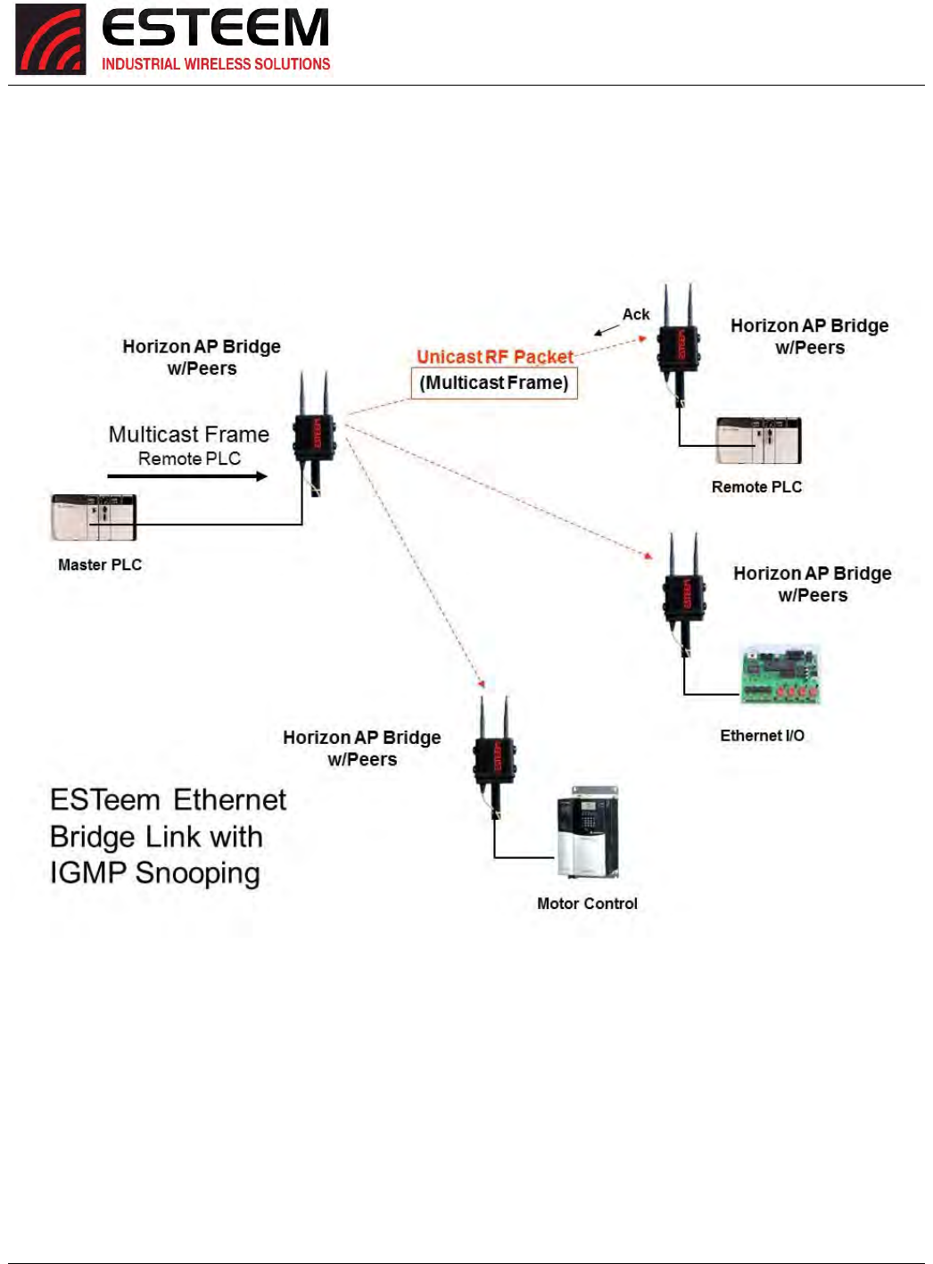
WhentheESTeemHorizonisconfiguredasarepeaterpeer,IGMPSnoopingisenabledandthenetworksupportsIGMPprotocol,
theHorizonwillbegintoidentifytheconnectedEthernetdevicesusingMulticasttransmissionsandreportthisinformationtothe
network.Asthisprocesscontinues,allsitesthathaveMulticasttrafficonthewirelessnetworkwillonlysendtheserequeststo
thespecificESTeemreportingtheEthernetdevice(seeFigure11).
Figure11:RepeaterPeerwithIGMPEnabled
CHAPTER4
UTILITIES&FEATURES
Revised: 25 Jan 17 4-9 ESTeem Horizon Series
EnablingIGMPSnooping
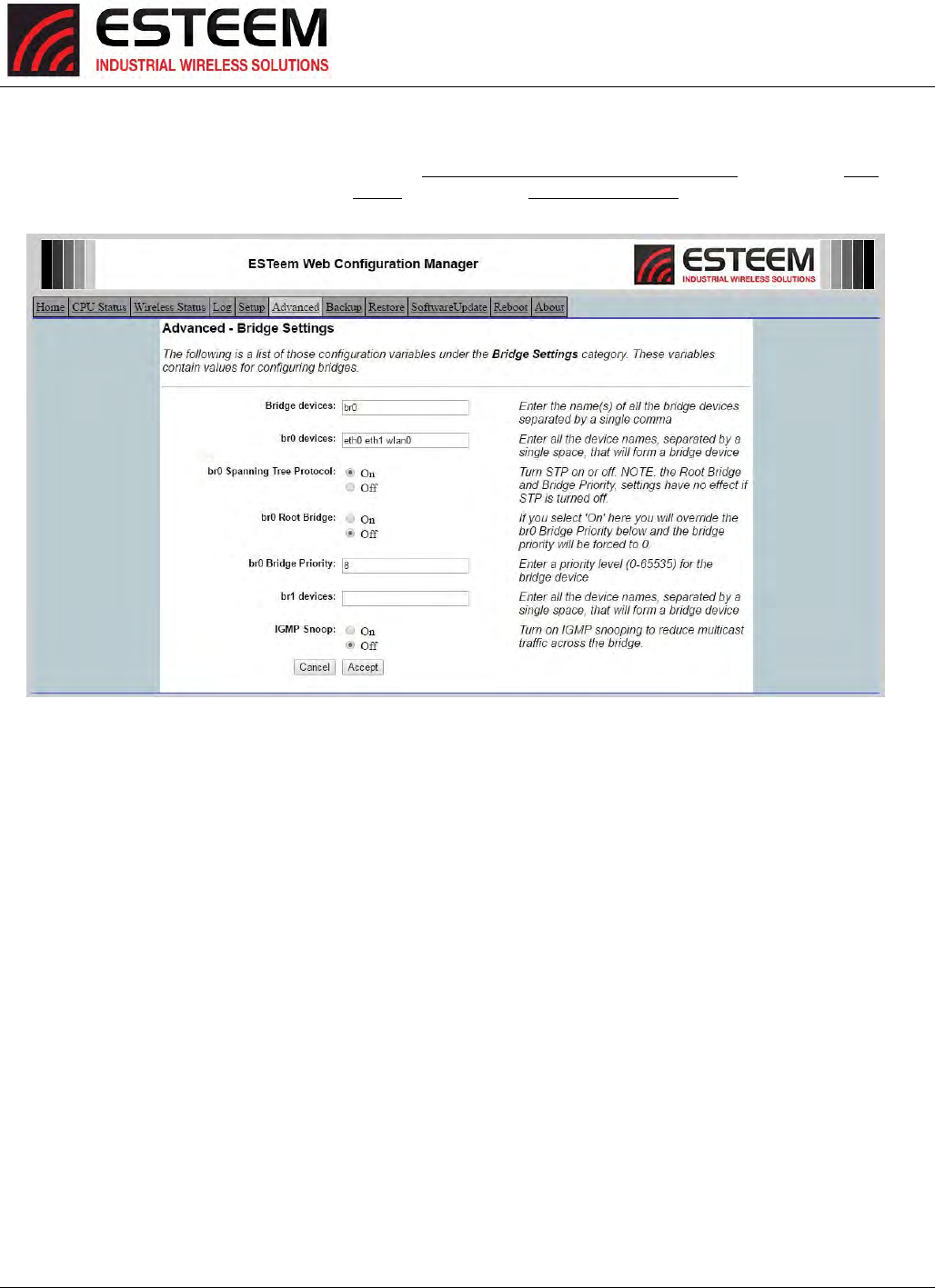
ToenabletheESTeemHorizonforIGMPSnooping,selectAdvanced>BridgeSettings>BridgeVariablesandpresstheNextButton
(Figure12).SelectIGMPSnooptoOn,presstheAcceptButtonandthenCommitandReboot.
Figure12:IGMPEnabled
CHAPTER4
UTILITIES&FEATURES
Revised: 25 Jan 17 4-10 ESTeem Horizon Series
ModbusMonitoring
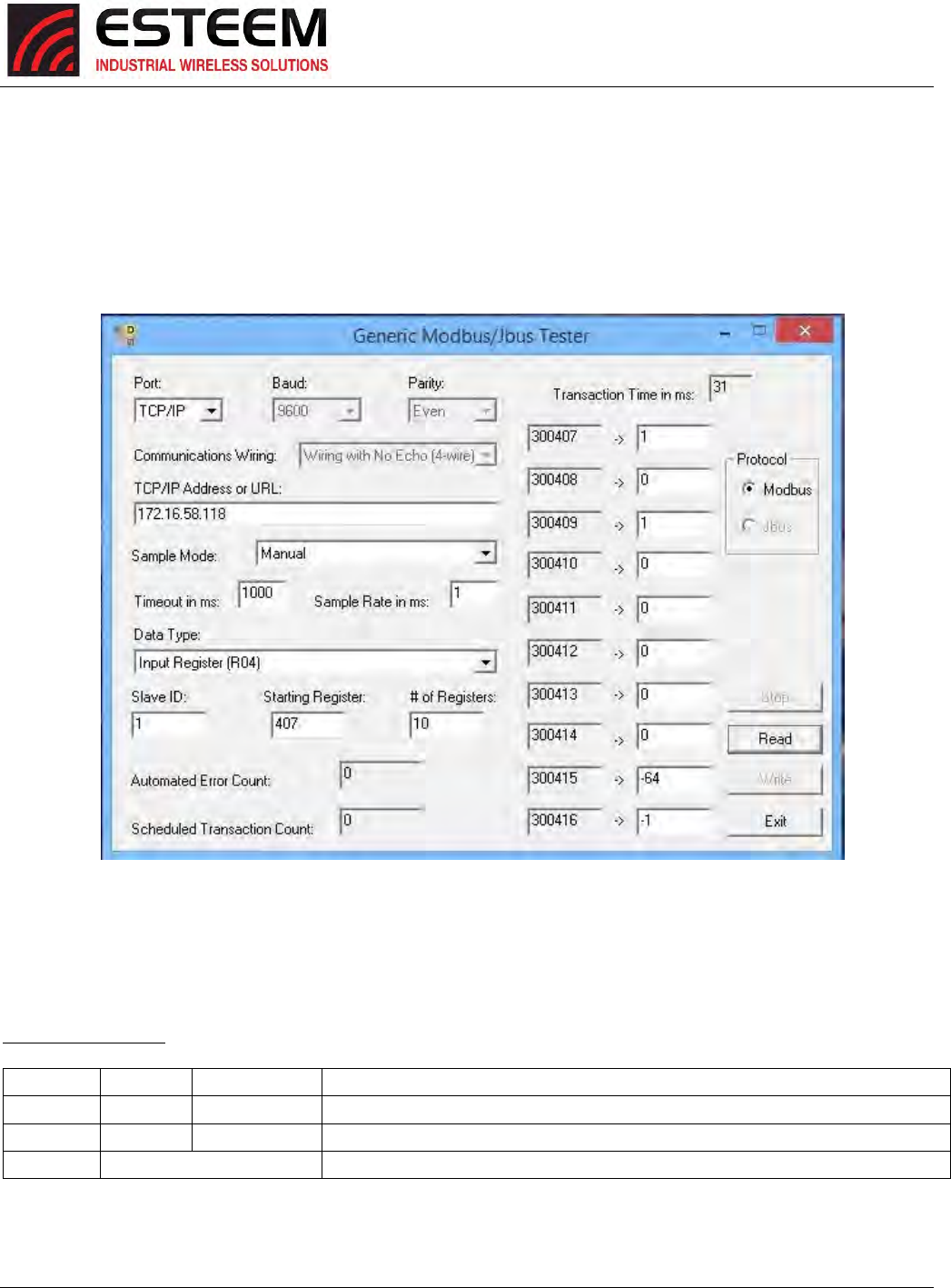
TheESTeemHorizonSeriessupportsModbusTCPprotocolforaccesstomultipleoperatingparametersinthewireless
modemandRFnetworkhealthstatus.Frequency,bandwidth,receivesignalstrength,RFdataratesandGPSdata
(withGPSoptioninstalled)areafewoftheregistersavailablethroughtheopenModbusTCPprotocol.WithHorizon
firmwareversion201701131128orlater,thisdatacanbeobtainedbypollingtheregistersdirectlyorusingavailable
utilities(Fig.1)
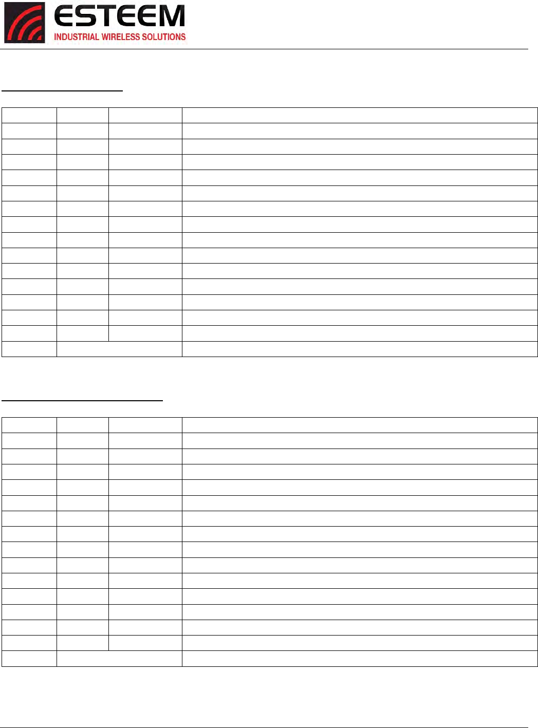
ThefollowingaretheModbusregisterssupportedintheESTeemHorizonSeriesonPort502.Registersaremapped
as32‐bitfloatingpointnumbers(2registerseach):
RadioInformation
FunctionRegisterExample
312412Frequency
3320ChannelBandwidth
5–199Reserved
Figure13:ModbusTestUtilityExample

CHAPTER4
UTILITIES&FEATURES
Revised: 25 Jan 17 4-11 ESTeem Horizon Series
GPSInformation(GPSOptionrequired)
FunctionRegisterExample
3201285815040Time(hh:mm:ss:ff)
320317Hours(hh)
32059Minutes(mm)
320749Seconds(ss)
32090FactionalSeconds(ff)
32119TotalSync’dSatellites
32131GPSFixed
32150HDOP
3217141AltitudeMeters
3219‐119LongitudeDegreesInteger
3221209786666LongitudeDegreesFractional
322346LatitudeDegreesInteger
3225214503333LatitudeDegreesFractional
322746214503LongitudeDegreesx10e6
3229‐119209786LatitudeDegreesx10e6
32310East=1West=0
3233119LongitudeDegrees
323512LongitudeMinutes
32375872LongitudeFractionalMinutes
32391North=1South=0
324146LatitudeDegrees
324312LatitudeMinutes
32458702LatitudeFractionalMinutes
32475120254NorthingInteger
3249213NorthingFractional
3251329555EastingInteger
3253252EastingFractional
325511ZoneNumber
325784ZoneLetter
259–399Reserved
CHAPTER4
UTILITIES&FEATURES
Revised: 25 Jan 17 4-12 ESTeem Horizon Series
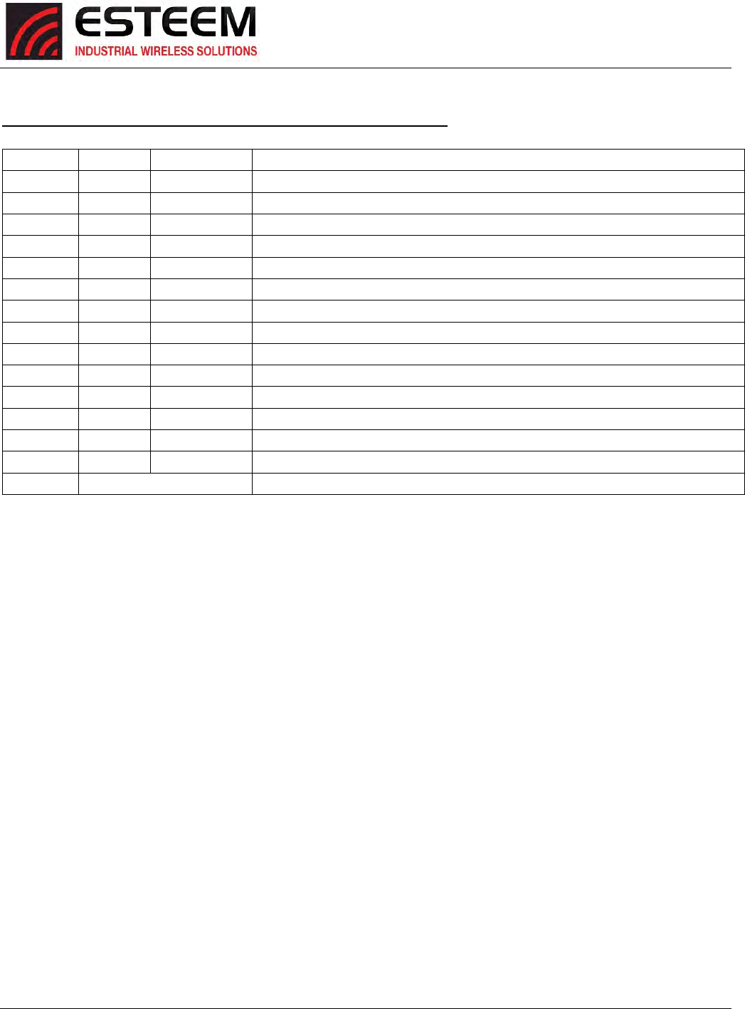
GlobalPeerInformation
FunctionRegister
3401 Reserved
3403 Reserved
3405 Reserved
3407 Ant1Enabled=1Disabled=0
3409 Ant2Enabled=1Disabled=0
3411 Ant3Enabled=1Disabled=0(currentlynotused)
3413 Ant4Enabled=1Disabled=0(currentlynotused)
3415 Ant1RSSI
3417 Ant2RSSI
3419 Ant3RSSI(currentlynotused)
3421 Ant4RSSI(currentlynotused)
3423 CurrentPeerRadioTime
3425 LastReceivedPacketTime
3427 LastReceivedDataRate/10ForPrecision
429–439Reserved
IndividualPeerLinkInformation
FunctionRegister
3441 PeerMACFirst2Bytes[XX:XX:00:4F]
3443 PeerMACLast4Bytes[03:A9:00:90]
3445 PeerPortForwarding=1Blocking=0
3447 Ant1Enabled=1Disabled=0
3449 Ant2Enabled=1Disabled=0
3451 Ant3Enabled=1Disabled=0(currentlynotused)
3453 Ant4Enabled=1Disabled=0(currentlynotused)
3455 Ant1RSSI
3457 Ant2RSSI
3459 Ant3RSSI(currentlynotused)
3461 Ant4RSSI(currentlynotused)
3463 CurrentPeerRadioTime
3465 LastReceivedPacketTime
3467 LastReceivedDataRate/10ForPrecision
469–479Reserved
CHAPTER4
UTILITIES&FEATURES
Revised: 25 Jan 17 4-13 ESTeem Horizon Series
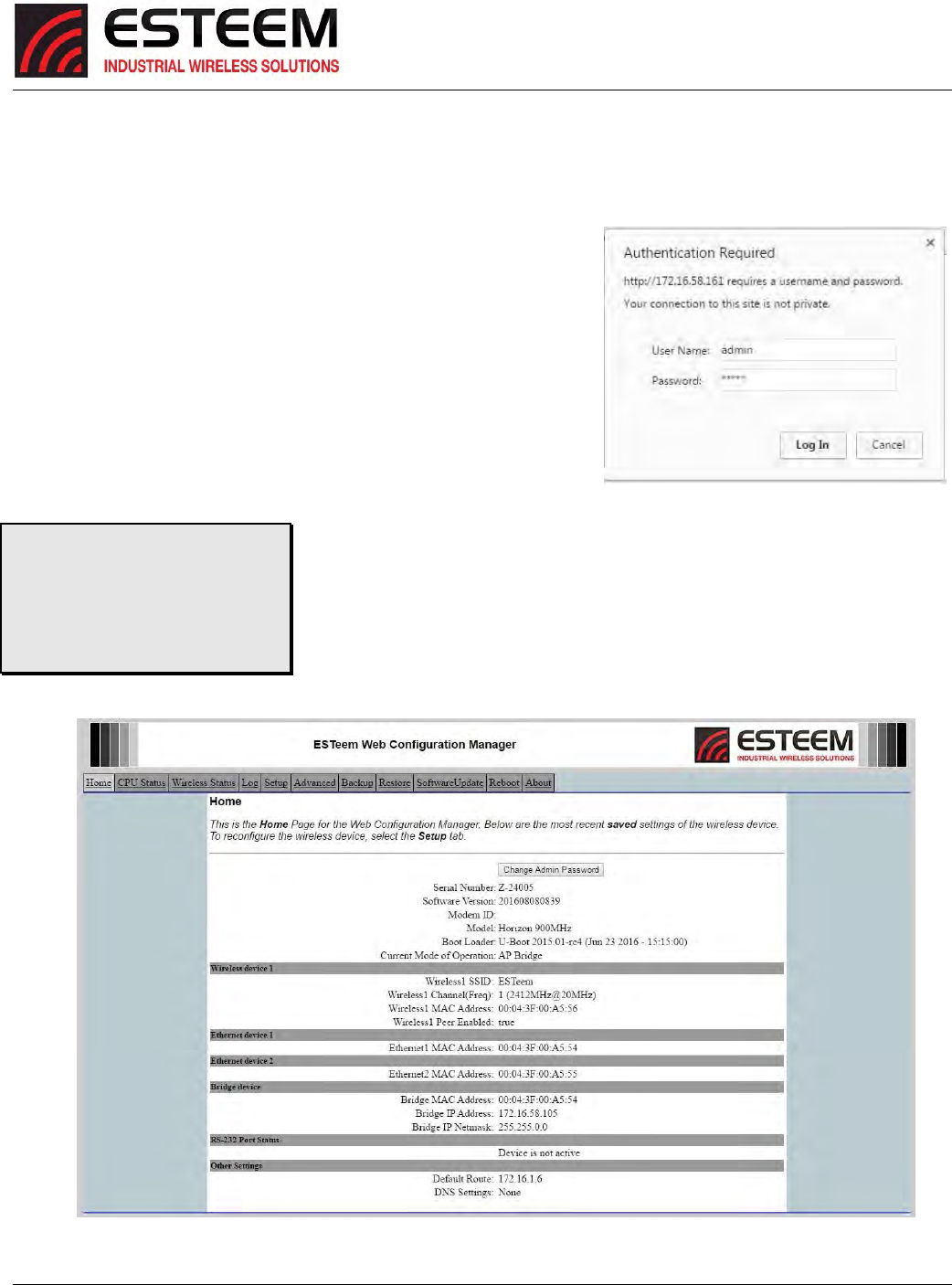
IndividualPeer#2LinkInformation(repeatableupto128Peers)
FunctionRegister
3481 PeerMACFirst2Bytes
3483 PeerMACLast4Bytes
3485 PeerPortForwarding=1Blocking=0
3487 Ant1Enabled=1Disabled=0
3489 Ant2Enabled=1Disabled=0
3491 Ant3Enabled=1Disabled=0(currentlynotused)
3493 Ant4Enabled=1Disabled=0(currentlynotused)
3495 Ant1RSSI
3497 Ant2RSSI
3499 Ant3RSSI(currentlynotused)
3501 Ant4RSSI(currentlynotused)
3503 CurrentPeerRadioTime
3505 LastReceivedPacketTime
3507 LastReceivedDataRate/10ForPrecision
509–519Reserved
CHAPTER5
WEBCONFIGURATION
Revised: 25 Jan 17 5-1 ESTeem Horizon Series
TheESTeemHorizonWebConfigurationManagerisaninternalwebserverthatwillallowsetup,monitoringanddiagnosticsofall
operatingparametersintheHorizon.TheHorizoncanbeconfiguredusinganycurrentwebbrowsersoftwaresuchasInternet
Explorer,Mozilla,FireFoxorGoogleChrome®.
LoggingontotheESTeemWebInterface
1. UsingyourWebBrowserconnecttotheHorizonWebInterfacewiththeIP
AddressthatyouhaveassigneditinChapter3.
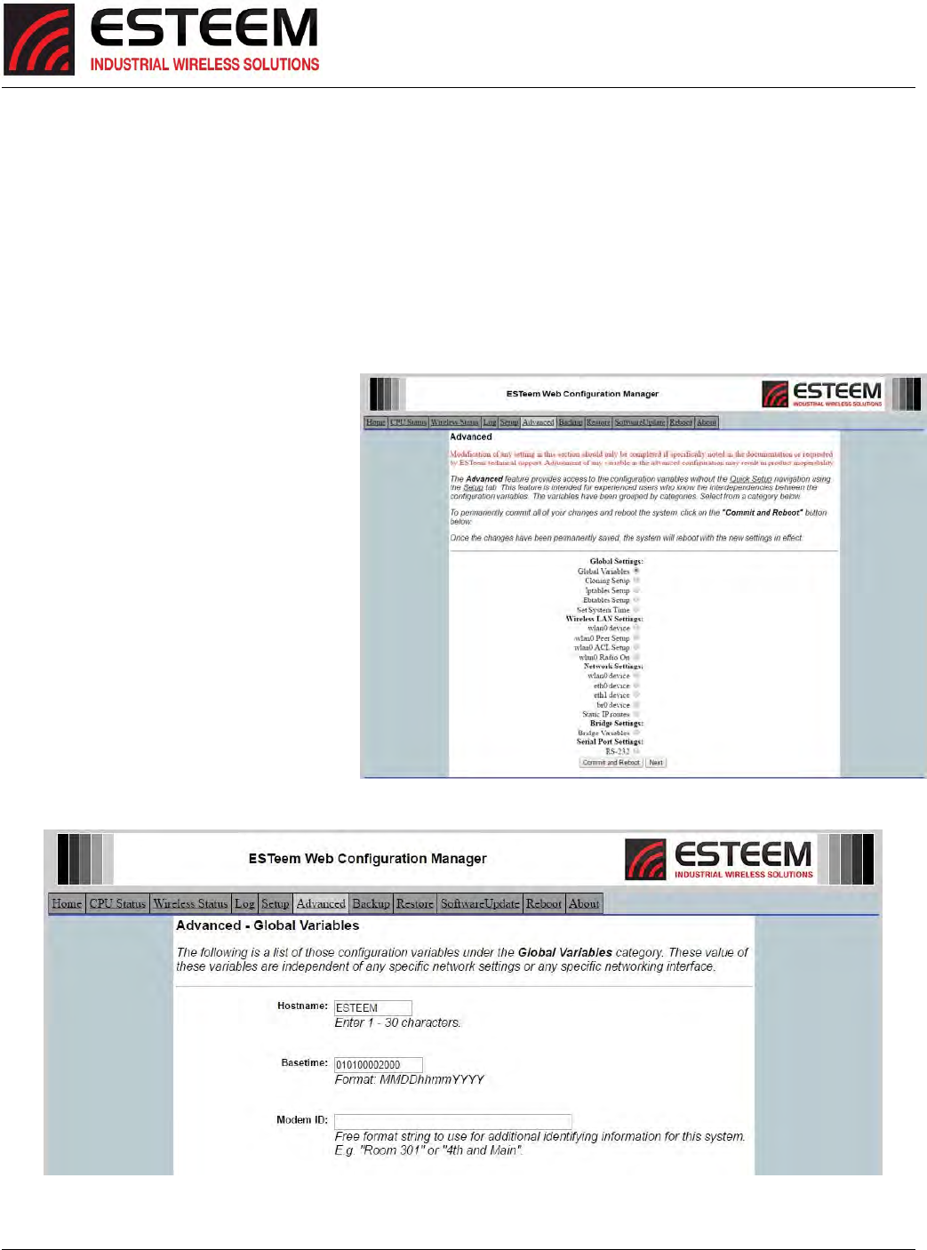
2. YouwillnowseetheLog‐onMenuonFigure1.ToentertheHorizonHome
MenuyouwillneedtologintothesystemwithaUserNameandPassword.
3. FortheUserNameenteradminandpresstheEnterkey(<Enter>).The
UserNameisdefinedatthefactoryandisnotchangeable.
4. EnteryourPasswordandpresstheEnterkey(<Enter>).
5. AfterLog‐inthenextscreen
displayedwillbetheHorizonHomepage(Figure2).ThisexamplescreenshowstheMain
Menuscreen.
Note:ThroughouttheConfigurationManagerareHelpScreensthatcanbeaccessed
forfurtherinformationoneachitem.
Figure1:ESTeemWebPageLog‐onScreen
TechnicalTip:Ifthisisthefirsttime
theHorizonhasbeenprogrammed
andthePasswordwasnotchanged
fromthefactorydefaultvalues,the
factorydefaultPasswordisalso
admin.
Figure2:HomeScreen
CHAPTER5
WEBCONFIGURATION
Revised: 25 Jan 17 5-2 ESTeem Horizon Series
WEBCONFIGURATIONMANAGERSECTIONS
Thefollowingsectionswilldescribethefeaturesineachofthemainandsubmenuitemsinthewebpages.Forstep‐by‐step
examplesofhowtoconfiguretheHorizonindifferentModesofOperation,pleaserefertoChapter3–ExampleApplications.
TopMenu
TheTopMenuwillbethedefaultwebpagefortheHorizonWebConfigurationManager(Figure2).Thissectionwilldisplaythe
currentconfigurationsummaryfortheHorizonandallowchangingofthedefaultpassword.ThispagewillalsodisplaytheModem
IDfieldthatcanbeusedtoeasilyidentifytheHorizonyouareprogramming.ThisModemIDfieldcanbesettoanytext
combinationforexample,locationname,GPScoordinatesoraddresses.
SettingtheModemID
1. TheModemIDfieldcanbeadjustedunder
theGlobalVariablesoftheAdvancedMenu
tab.SelectGlobalVariablesandpressthe
Nextbutton.Figure3willbedisplayed.
2. ScrolltothebottomoftheGlobalVariables
windowandenterthetextyouwouldlike
displayedintheModemIDfield(Figure4).
Whencomplete,presstheSaveSettings
buttonandtheCommitChangesbuttonon
thenextscreentosavethenametothe
Horizon.
Figure3:AdvancedGlobalSettingsScreen
Figure4:ModemIDFieldinGlobalVariablesScreen
CHAPTER5
WEBCONFIGURATION
Revised: 25 Jan 17 5-3 ESTeem Horizon Series
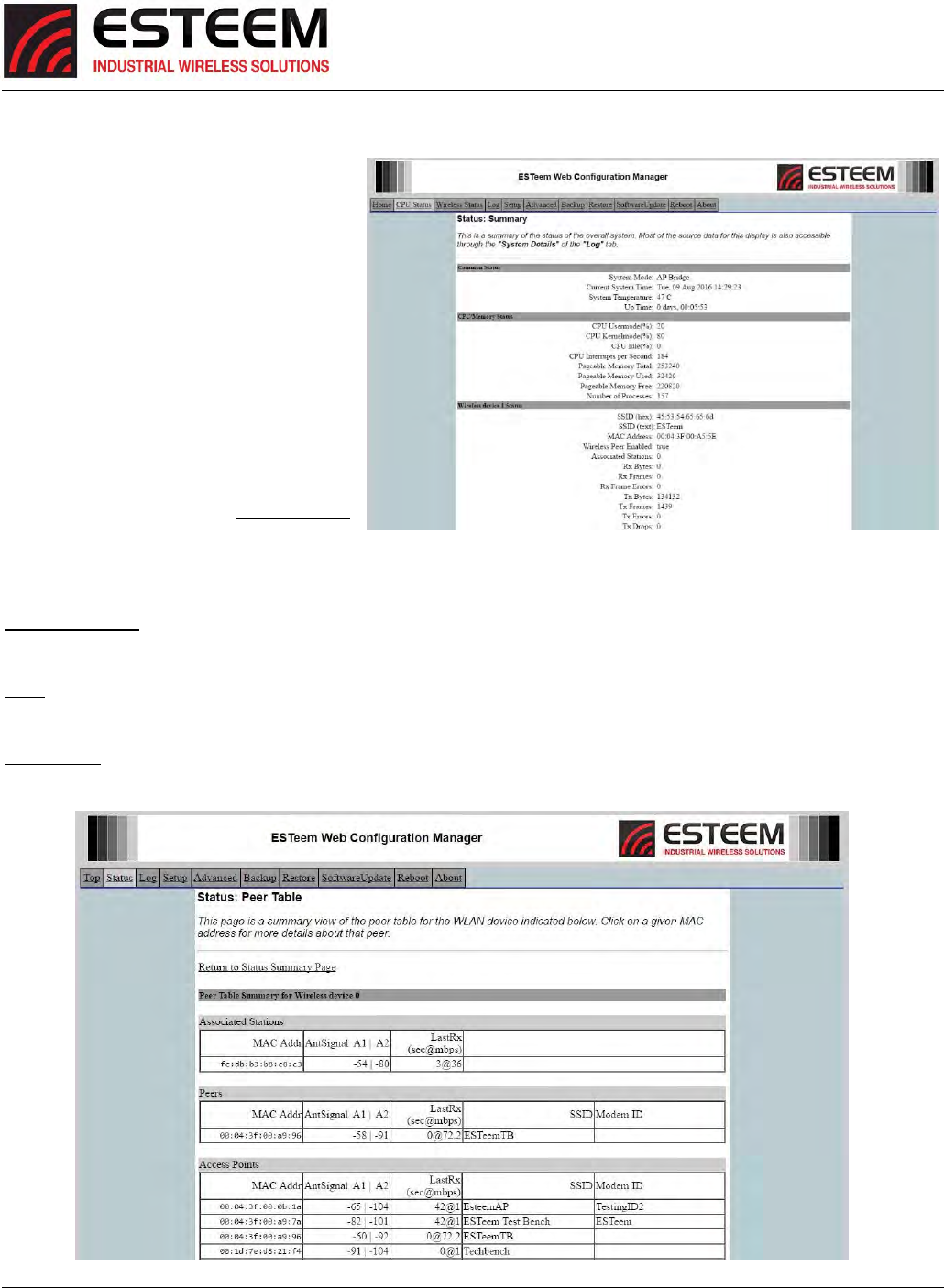
CPUStatus
TheStatusMenuprovidesasummaryofthe
currentmodeofoperation,systemtime,
processorusage,internaltemperatureand
statusofthecommunicationlinkstoother
wirelessdevices.Anexampleisshownbelowin
Figure5.Mostofthecommunication
troubleshootingisdoneinthissectionofthe
WebConfigurationManager.
WirelessStatus
TheWirelessStatussubmenuliststhe
connectedwirelessdevices(Horizon’sor802.11
clients),theirsignalstrength,datarateandtime
oflastpacketsent.PresstheWirelessStatus
linkandPeerStatusTablewillbedisplayed
(Figure6).Foradetailedanalysisofthe
informationprovidedinthistable,pleasereviewAppendixE–Troubleshooting.
AssociatedStation–ThissectionwilllistalltheassociatedstationsthatareattachedtotheAccessPoint.Thesecouldbeother
Horizon’sinoneofthethreeClientmodesor802.11devices.
Peers–ThissectionwilllistallconnectedHorizonpeers(EthernetBridgelinks)bytheirWirelessMACaddress.Fordetailed
informationonpeerlinks,bridgingandwirelessMesh,seeChapter7–WirelessBridgingandMeshFeatures.
AccessPoints–Thissectionwilllistallother802.11AccessPointsthataresharingtheoperatingchannel(frequency)oftheHorizon.
YoucanalsonotethatthePeerslistedabovearealsoincludedinthislist.
Figure5:StatusScreen
Figure6:PeerTableScreen
CHAPTER5
WEBCONFIGURATION
Revised: 25 Jan 17 5-4 ESTeem Horizon Series
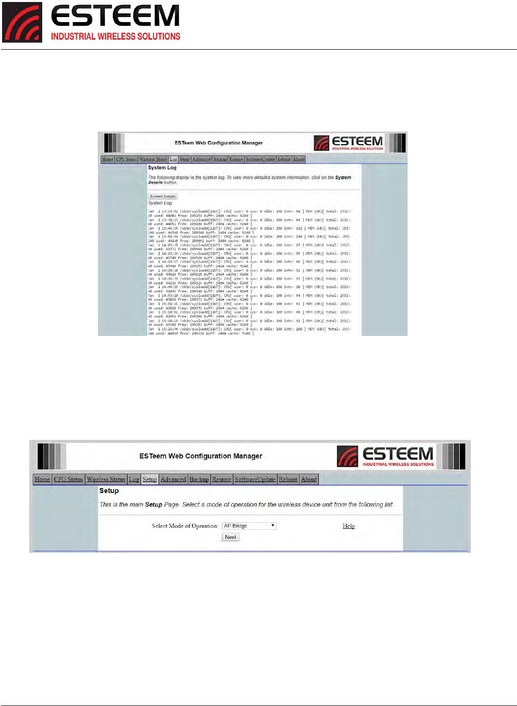
SystemLogScreen
TheLogScreenisatrouble‐shootingtoolthatshowsthecurrentlogofHorizonsystemmessages.SeeFigure7.TheSystemDetails
buttonwilldisplayamoredetailedsystemdiagnosticthatmayberequestedbyESTeemtechnicalsupport.
SetupScreen
TheSetupscreenallowsthestep‐by‐stepconfigurationoftheHorizonusingtheWebConfigurationManager(Figure8).Please
seeChapter3forcompletedescriptiononModesofOperationandexamplesystemconfigurations.
Figure7:SystemLogScreen
Figure8:SetupScreen
CHAPTER5
WEBCONFIGURATION
Revised: 25 Jan 17 5-5 ESTeem Horizon Series
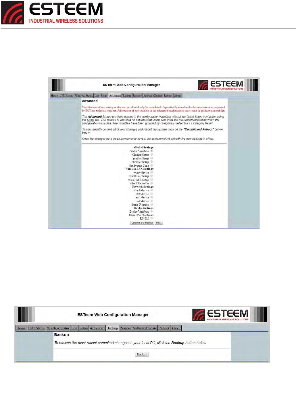
AdvancedConfigurationScreen
TheAdvancedscreenallowstheusertoaccessallconfigurationparameters.Theparametersaregroupedbasedupontheir
variable.ItisrecommendedthatonlyadvancedusersoftheHorizonenterthissectionunlessinstructedbyESTeemtechnical
support.SeeFigure9.
BackupScreen
TheBackupScreensavesthecurrentconfigurationintheHorizontoafileonthecomputerornetwork.SeeFigure10.Pressing
theBackupButtonwillcreateaconfigurationfilethatcanbesavedtothecomputer.Thissavedfilecanthenbelateropened,if
necessary,bytheRestoremenutoquicklyreplaceaHorizonwithasparemodem.
Figure9:AdvancedFeaturesScreen
Figure10:BackupScreen
CHAPTER5
WEBCONFIGURATION
Revised: 25 Jan 17 5-6 ESTeem Horizon Series
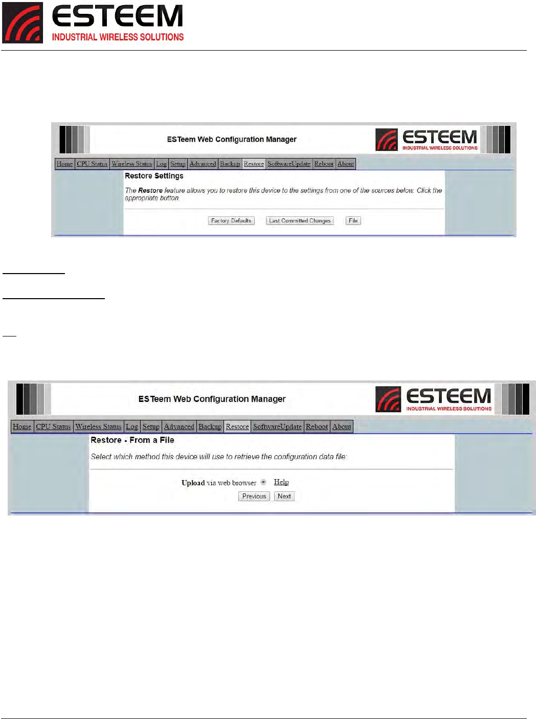
RestoreScreen
TheRestorescreenisusedtorestoretheHorizontofactorydefaults,returntothelastsavedconfigurationortoaccessthe
configurationfilesthatwerebackeduptothecomputer.SeeFigure11.
FactoryDefault–ReturnstheHorizontoallfactorydefaultvalues.
LastCommittedChanges–Thisbuttonwillremoveanychangestothemodemthathavebeendonesincethelastcommitted
changes.ThelastcommittedchangeswillbereadfromtheFlashfileandresetintheHorizon.
File–PressingthisbuttonwillbringupaselectionofwheretherestorefilewassavedduringtheBackup(Figure12).Select
“Uploadviawebbrowser”tobrowseforfilessavedonalocalcomputerorselect“DownloadfromanhttporftpURL”forfiles
savedonanetworkorovertheInternet.
Figure12:RestorefromLocalFileScreen
Figure11:RestoreSettingScreen
CHAPTER5
WEBCONFIGURATION
Revised: 25 Jan 17 5-7 ESTeem Horizon Series
SoftwareUpdateScreen
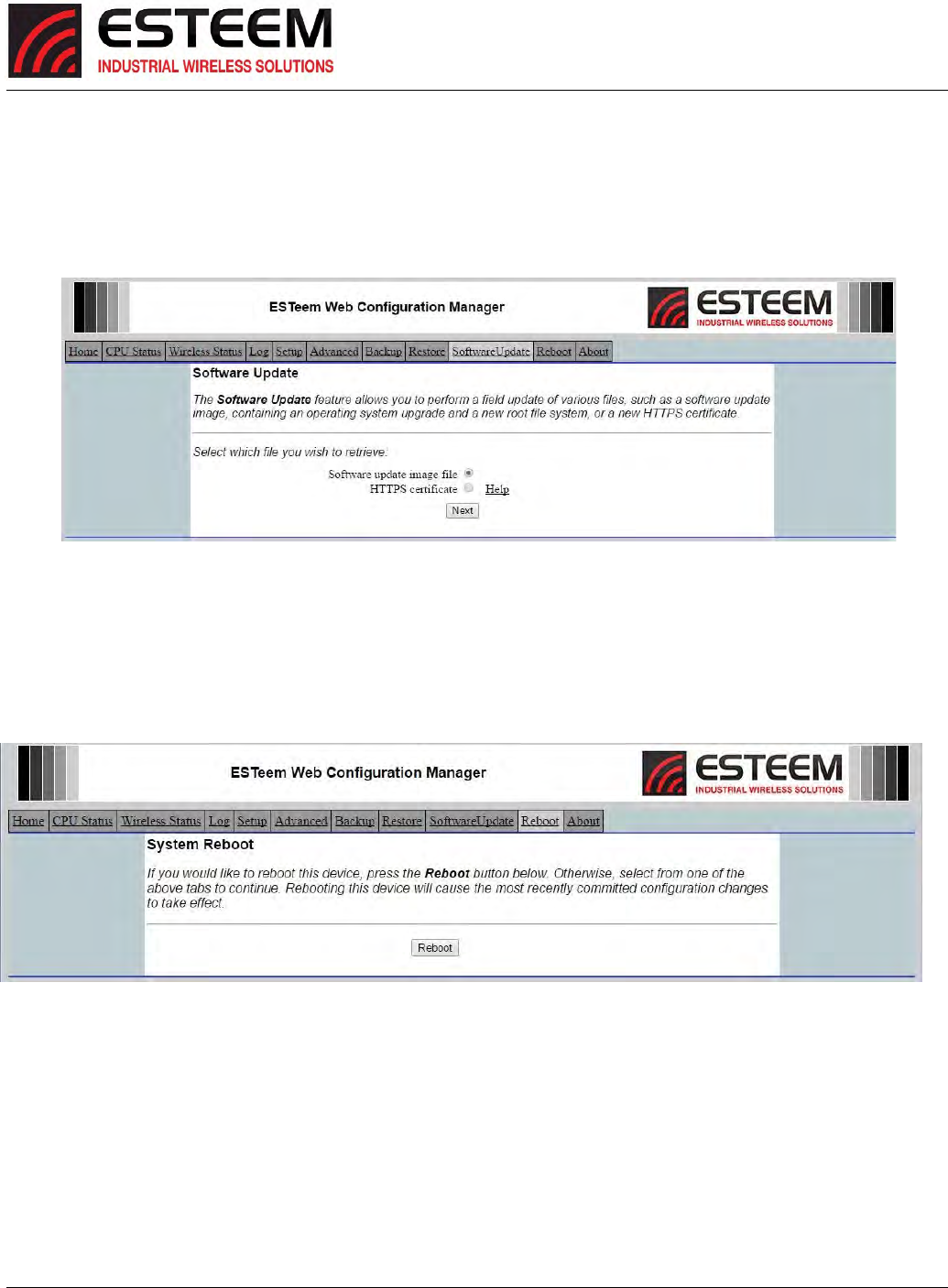
TheSoftwareUpdatefeatureallowstheusertoupdatethelatestHorizonoperatingsystemsoftwarefromafilesuppliedbythe
factoryortheInternettotheHorizon’sflashmemory.Touploadfromafileonyourcomputer,selectUploadviawebbrowserand
afileselectionwindowwillbedisplayed.TouploaddirectlyfromtheInternet,selectDownloadfromanhttporftpURLandenter
thesiteaddress.SeeFigure13.
SystemRebootScreen
TheRebootscreenallowstheusertoresettheHorizon.SeeFigure14.
Figure13:SoftwareUpdateScreen
Figure14:SystemRebootScreen
CHAPTER6
SERIALAPPLICATIONS
Revised: 27 Jun 16 6-1 ESTeem Horizon Series
UsingTheRS‐232ProgrammingPort
TheRS‐232ProgrammingPortwillprovidealimitedsetcriticalprogrammingfeaturessuchassettingtheIPaddressorrestoring
theHorizonradiotofactoryfaults.AnyterminalemulationprogramthatcanrunwithVT100emulationcanbeusedforthis
configurationoftheESTeemHorizon.AnyRS‐232terminalprogram(suchasPuTTY‐http://www.putty.org)willwork.Configure
yourRS‐232portforaBaudRateto38,400,DataBitsto8,ParitytoNone,StopBitsto1andHandshakingtoNone.Onceyour
HorizonhasanIPaddress,youcanattachtheESTeemtoyournetworkandusetheWebConfigurationManager(Chapter5for
completedetails)forfurtherprogramming.
ProgrammingUsingtheRS‐232ProgrammingPort
1. Connecttheserialcable(ESTP/N:AA0621.1)betweentheRS‐232connector(RJ‐45)ontheHorizon’sRS‐232Programming
Porttotheserialportonthecomputer.
2. Ifyourcomputerisconfiguredproperly,youwillseetheESTeemHorizonbootingsequenceonyourTerminalEmulation
program.OncetheESTeembootsequenceiscomplete(approximately60seconds)youwillreceivethismessage:
“PleasepressEntertoactivethisconsole.”
Ifyoudon’tseethismessagepresstheResetbuttononthefrontpaneloftheHorizonand/orchecktheprogrammingofyour
RS‐232port.
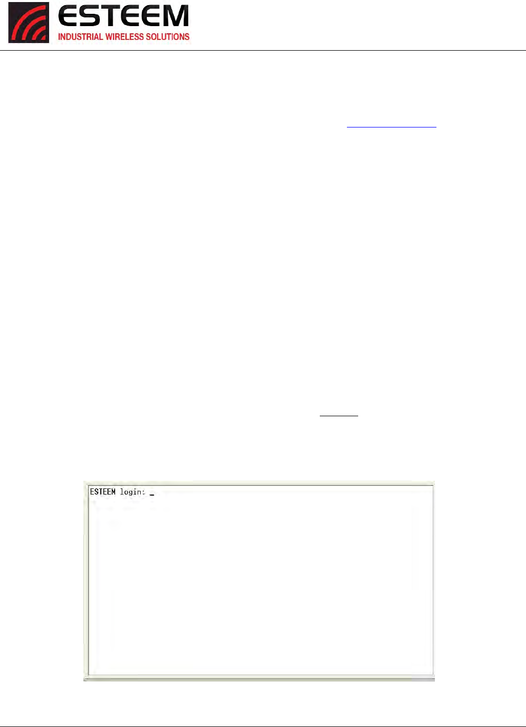
3. PresstheEnterkeyandyouwillbeattheConfigurationMenuHorizonloginprompt.SeeFigure1.
4. ToentertheHorizonMainMenuyouwillneedtologintothesystemwithaloginnameandpassword.
5. IfthisisnotthefirsttimeconfigurationoftheHorizon,seeyournetworksystemsadministratorforthepassword.
6. AttheHorizonloginprompttypeadminfortheloginnameandpresstheEnterkey(<Enter>).Theloginnameisdefinedat
thefactoryandisnotchangeablebytheuser.Notethatallcharactersarelowercase.
IfthisisthefirsttimetheHorizonhasbeenprogrammedorthePasswordwasnotchangedfromthefactorydefaultvalues,the
factorydefaultpasswordisalsoadmin.EnteradminforthepasswordandpresstheEnterkey(<Enter>).
Figure1:RS‐232PortLog‐inScreen
CHAPTER6
SERIALAPPLICATIONS
Revised: 27 Jun 16 6-2 ESTeem Horizon Series
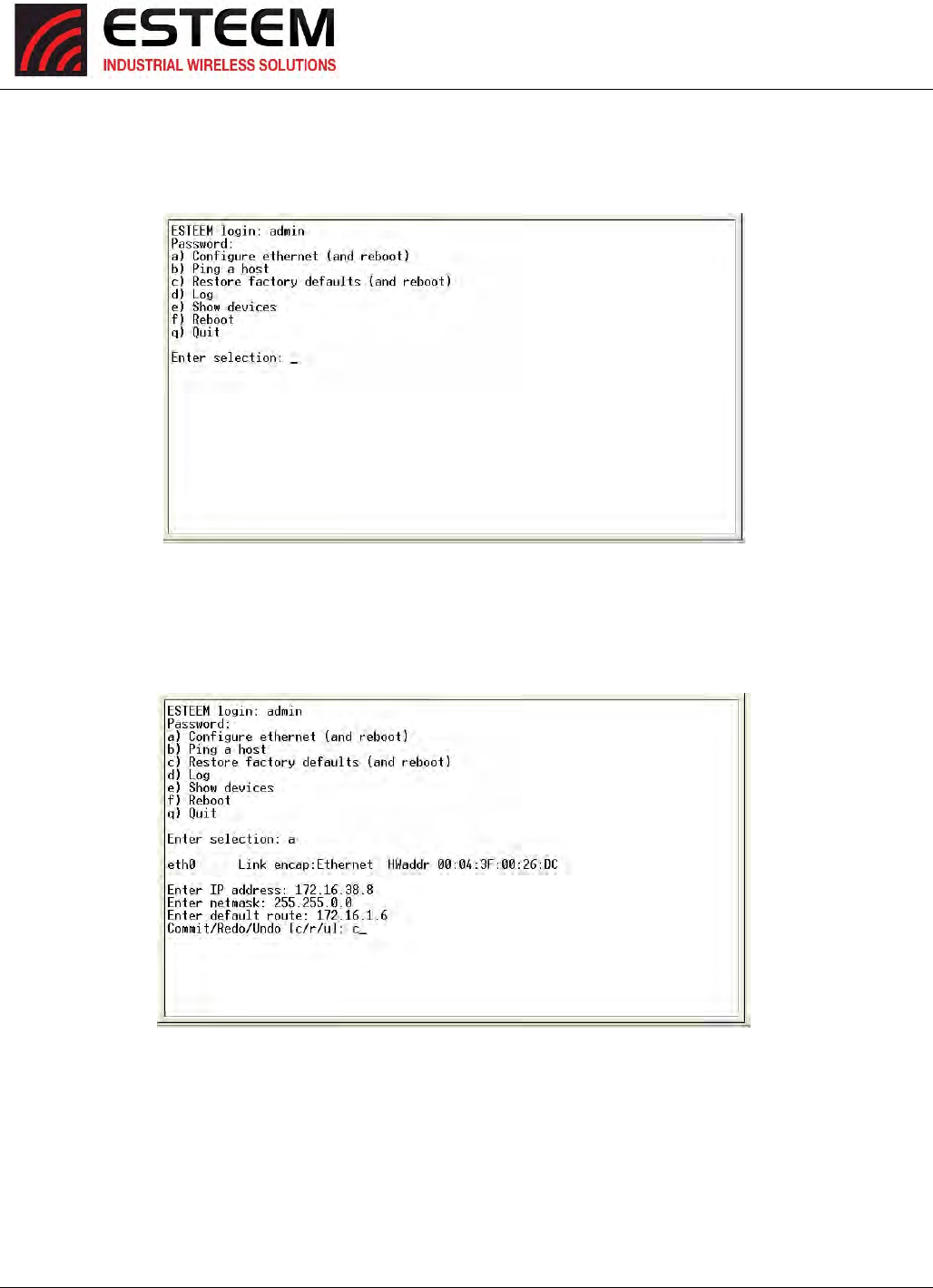
7. TosettheIPaddressintheESTeemHorizon,typetheletter“A”andpresstheEnterkey.EnterthevaluefortheIPaddress,
NetmaskanddefaultroutepressingtheEnterkeyaftereachentry.
8. AfterthebasicparametershavebeenenteredintotheHorizonyouwillneedtocommitthechangestotheHorizon(Figure
3).PresstheCkeyandthenEnter.Thechangeswillbesavedtoflashmemory.Youcanuseprogrammingfeaturesinthe
ESTeemWebConfigurationManagertoconfiguretheunitforyourapplication.
Figure2:RS‐232WelcomeScreen
Figure3:RS‐232WelcomeScreen
CHAPTER6
SERIALAPPLICATIONS
Revised: 27 Jun 16 6-3 ESTeem Horizon Series
UsingTheRS‐232DataPort
TheESTeemHorizonhasaserialdataportthatcanprovideRS‐232communicationbetweentwoormoreserialdevicesusingthe
wirelessbroadbandlink.TheserialdataisencapsulatedandtransferredasastandardEthernetpacketoveranoperatingHorizon
wirelessEthernetsystem.TheconfigurationforaserialHorizonnetworkwillbethesameasanEthernetoraserial(RS‐232)based
communicationnetwork.
Theserialinterfaceoptioncanbeusedtolinktwoormoreserialdevicesinaneworexistingsystem.Theserialdatahasverylittle
impactonthenetworkbandwidthandwillallowforbothEthernetandserialapplicationssimultaneously.Apossibleapplication
wouldbeinstallationoftheHorizoninanexistingserialbasednetworkthatwaslookingforfutureupgradetoanEthernetbased
system.Anotherwouldbeusingthehigh‐bandwidthEthernetconnectionstoprovidealinktoremotevideohardwarewhilealso
providingaseriallinktotheexistingPLCinaSCADAtypeapplication.
SerialConnections
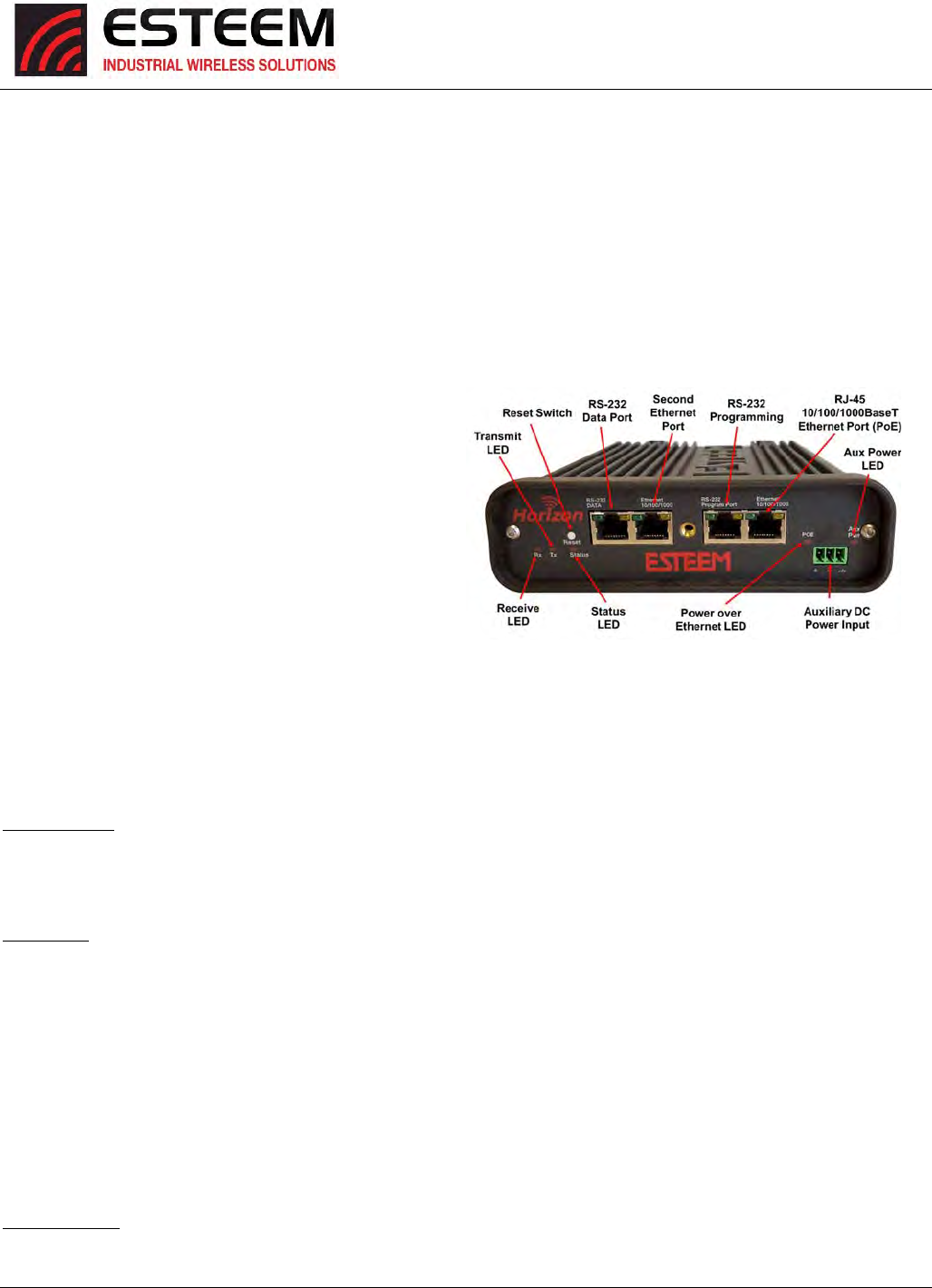
TheRJ‐45serialdataportisthefar‐leftportonthefaceofthe
Horizon(Figure4).UsingtheESTeemAA0621.1interface
cable,theHorizoncanbeconnectedtoastandardDTE‐
device(PC)withamale9‐pinSub‐Dconnector.Thecomplete
cableconfigurationisavailableinAppendixC–Interface
Ports.
SerialConfiguration
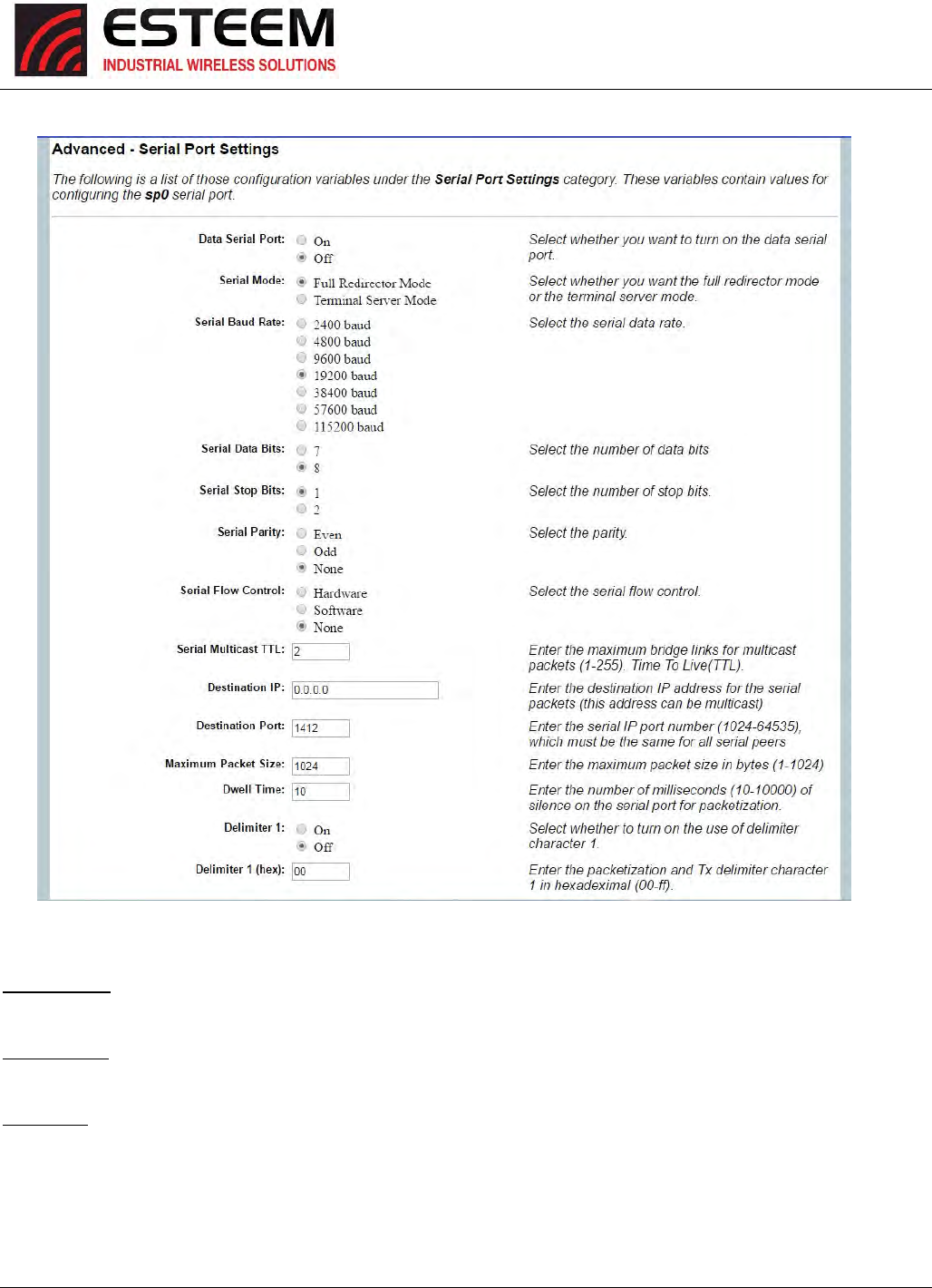
ConfigurationoftheserialportisdoneinAdvanced>SerialPortSettings.SelectSerialPortSettings>RS‐232andpresstheNext
button,theSerialPortSetupscreen(Figure5)willbedisplayed.EachsectionintheSerialPortSetupscreenisdescribedindetail
withthefollowing:
DataSerialPort
EnablingtheserialdataportallowsthemodemtosendRS‐232dataoverthebroadbandwirelessconnectionestablishedwiththe
ESTeemrepeaterpeers.Themodemcanbeconfiguredinapoint‐to‐pointorpoint‐to‐multipointsystem.SelectYesifyouwish
toenabletheserialdataport.
SerialMode
TherearetwodistinctmodesofoperationfortheserialportintheHorizon.TheRedirectormodewillprovidetwo‐wayserial
communicationbetweentwoormoreserialdevices,whiletheTerminalServermodewillallowserialcommunicationtoaspecific
remotesitebyconnectingthroughtelnetorSSH.Selectoneofthefollowingmodesofoperation:
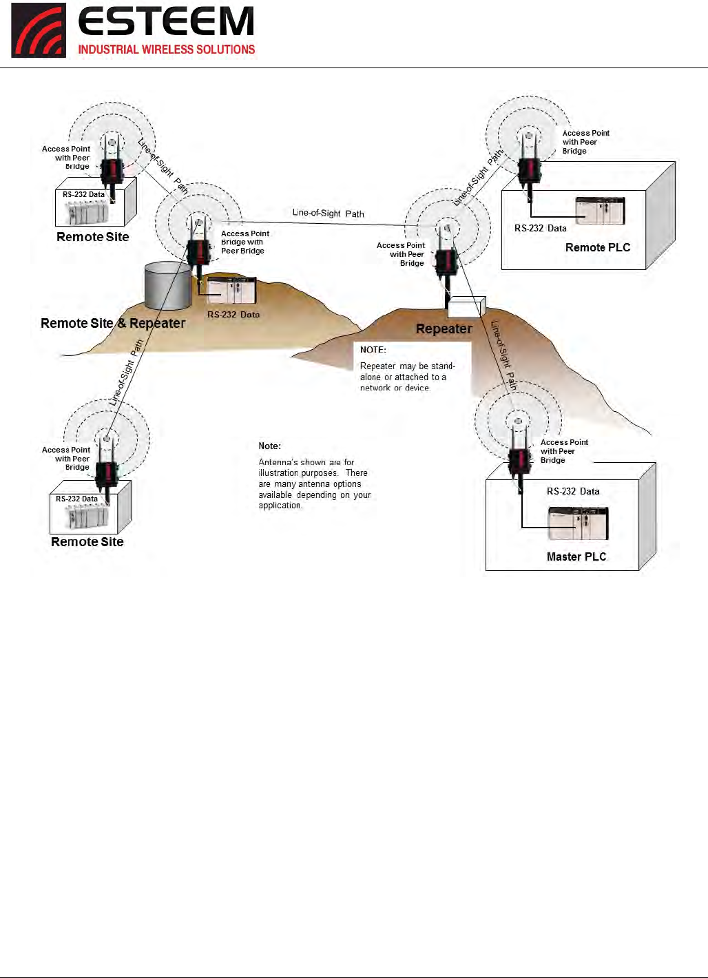
FullRedirectorMode‐Thismodeallowsbi‐directionalRS‐232datacommunicationwithotherESTeemHorizon’s.TheRS‐232data
transmissionwillappeartransparenttotheconnecteddevicesasifaserialcableisconnectedbetweenthetwoports.Thismode
willalsobeusedinamulti‐pointserialnetworkwereallserialdeviceswillneedbi‐directionalcommunication(Figure6).
TerminalServerMode‐ThismodeofoperationtranslatesRS‐232serialdataintoanetwork‐orientedterminalprotocol,suchas
telnetorSSH.ThismodewouldbeselectedifaninteractiveRS‐232sessionatremotelocationsisdesiredoverthewireless
Ethernetlink.
SerialBaudRate
SelectthedatarateoftheRS‐232connectiontomatchyourserialdevice.
Figure4:HorizonFrontPanelOverview
CHAPTER6
SERIALAPPLICATIONS
Revised: 27 Jun 16 6-4 ESTeem Horizon Series
SerialDataBits
SelectthenumberofdatabitsontheRS‐232connectiontomatchyourserialdevice.
SerialStopBits
SelectthenumberofstopbitsontheRS‐232connectiontomatchyourserialdevice.
SerialParity
SelecttheparityoftheRS‐232connectiontomatchyourserialdevice.
Figure5:SerialConfigurationScreen

CHAPTER6
SERIALAPPLICATIONS
Revised: 27 Jun 16 6-5 ESTeem Horizon Series
SerialFlowControl
SelectthetypeofdataflowcontrolusedontheRS‐232connection.TheESTeemcansupportHardwareflowcontrol(RTS/CTS
controllines)orSoftwareFlowControl(XON/XOFF).SelectNoneifnoserialflowcontrolisnecessary.
SerialMulticastTTL(MaximumBridgeLinksforMulticastPackets)
ThisvaluesetsthemaximumnumberofEthernetbridgelinksthatthemulticastpacketswillbesentthroughwhenusedinamulti‐
pointsystem.Amulti‐pointserialnetworkusesmulticastpackets(UDP)tosendthedatatomorethanoneremoteESTeem.You
wanttolimitthenumberofnetworkbridgelinksthattheseUDPpacketswillbepassedthroughtomakethenetworkmore
efficient.
IfyouareusingmultipleESTeemrepeaterlinkstosendtheserialdatatoremotelocations,thevalueforthemaximumbridgelink
needstobeincreasedtoanumbergreaterthanthelongestrepeaterchain.Forexample,ifyouareusingfourrepeater(peer)
linkstosendtheserialdatabetweentwoormoresitesthenumberwillneedtobefive(5)orgreater(Figure4).
DestinationIPAddress
TheESTeemconfiguredforthecorrectdestinationIPandportnumberwillsendandreceivetheserialdatafromanothermodem.
SetthedestinationIPaddressfortheESTeemwheretheserialdatawillbesent.IfsendingtomorethanoneESTeem(Multipoint)
settoamulticastaddress(i.e224.0.0.1).
Note:IfyouareusingtheESTeemHorizoninamultipointapplication(multicast),youmusthavedefaultGatewayconfiguredin
theESTeemsettotheIPaddressoftheRootBridgemodem.
DestinationPort
TheESTeemconfiguredforthecorrectdestinationIPandportnumberwillsendandreceivetheserialdatafromanothermodem.
SettheIPportnumberstomatchwheretheserialdatawillbesent.TheserialdatawillnotbesentifboththeIPaddressandport
numberisnotcorrect.
MaximumPacketSize
Thisnumberrepresentsthemaximumsizeoftheserialdatapacketinbytes.Ifthenumberofbytesofdataintheserialportbuffer
exceedsthemaximumpacketsizebeforethetimerordelimitercharacterisreached,theESTeemwillsendforwardtheserial
packet.Forexample,ifthemaximumpacketsizeissettoavalueof100,whentheserialportreceives100bytesthedatawillbe
sentthroughthewirelessconnection.
DwellTime(NumberofMillisecondsforPacketization)
ThisnumberrepresentsthetimetheESTeemwillholddataintheserialdatabufferbeforesendingtotheremoteESTeem.This
featureisgenerallyusediftheserialdatadoesnothaveaconsistentpacketlengthordelimitercharacter.Forexample,ifthe
numberofmillisecondsissettoavalueof10theESTeemwillmonitortheincomingserialdatastreamandanybreakincharacters
longerthan10millisecondswillcausethedatawillbesentthroughthewirelessconnection.
DelimiterCharacters
Enablingandspecifyingadelimitercharacterwilltransmitthedataintheserialbufferwhenthedelimitercharacterisrecognized
intheserialdatastream.Therearetwouniquedelimitercharactersthatcanbeconfiguredandenabledindependently.
ModemControlLines
EnablingthisfeaturewillallowtheESTeemintheTerminalServermodetoreadandgeneratemodemcontrollinestothe
connecteddevice.
CHAPTER6
SERIALAPPLICATIONS
Revised: 27 Jun 16 6-6 ESTeem Horizon Series
Figure6:SerialFullRedirectorExample
CHAPTER7
BRIDGELINKSANDMESH
Revised: 09 Aug 2016 7-1 ESTeem Horizon Series
Toincreasethewirelessnetwork’sareaofcoveragefor
bothindoorandoutdoorapplications,theHorizonutilizes
acustommeshingfeaturethatallowsincreasedcoverage
areaswithouttheaddedexpenseofhardcablingor
addinganadditionalpointtopointradiolink.
WithaconventionalIEEE802.11(Wi‐Fi)AccessPoint(AP)
network,alloftheAPshavetobeinterfacedtoacommon
networkeitherbyhardwire,seeFigure1,oraseparate,
dedicatedRFbackbone.TheModelHorizoncancreatethisRFbackbone,bridgeEthernetnetworksconnectedtothewired
Ethernetportandprovidethewirelesscanopyfor802.11clientssimultaneously.
WhenprogrammedinanyofthethreeAccessPoint(AP)Modes(Bridge,RouterorMasquerade),theHorizonwillcreateawireless
networkwithotherHorizonunitsinradiorangethatareprogrammedinthePeertableduringsetup.Thisfeatureaddsthe
increasedfunctionalityofrepeaterstothetypicalEthernetBridgeconfiguration.
ESTeemMeshNetwork
OneofthemostpowerfulfeaturesoftheAPPeerMode
istheabilitytoinputmultiplecommunicationroutesand
designatethepriorityforeachoftheseroutestocreatea
wirelessMeshnetwork.TheESTeemHorizonwill
automaticallychangecommunicationroutesinthe
networkifaroutehasfailed.Thenewroutewillbebased
upontheprioritylevelsetduringconfiguration.This
wirelessMeshingtechnologyallowstheRFnetworkto
“self‐heal”ifanyofthecommunicationpathsfail.
Theroutingpriorityismanuallysetduringthe
configurationoftheHorizon.Amanualpath
configurationisfarsuperiortostandard“self‐discovery”
networks,becauseyouhavedirectcontroloverthebest
RFpathsandcaneasilyidentifyanyfailedroutesforeasy
troubleshooting.Forexample,Figure2showsatypical
wirelessEthernetsystemusedintheWater/WasteWater
Industry.Theproblemwithastandard“self‐discovery”
Meshnetworkistheselectionofroutes.NoticethatthecommunicationbetweentheWaterPlant(SiteA)andPumpSiteDhasa
marginallink,butitisthemostdirectroutebetweentheEthernetdevices.
Thisscenarioposesthequestion,whichpathwillthenetworkselect?TheESTeemMeshNetworktakesouttheguessinggames
byallowingtheusertoselectandprioritizeallcommunicationroutesinthesystem.Inourexamplewewouldwanttheprimary
linktogothroughTankB(Repeater)andusethedirectlinkonlyifthisprimarylinkfails.Thefollowingsectionswillshowhowthis
completed.
Configuration
TheconfigurationofthewirelesspathsiscompletedduringsetupoftheAccessPointmodes.AllthreeAccessPointmodessupport
repeatingandMeshingfeatures.TheMeshnetworkconfigurationusingtheESTeemNetworkConfiguration(ENC)Utilityisshown
indetailinChapter3ofthisUser’sManual.
Figure1:ConventionalAccessPointDiagram
Figure2:SmallMeshNetworkDiagram
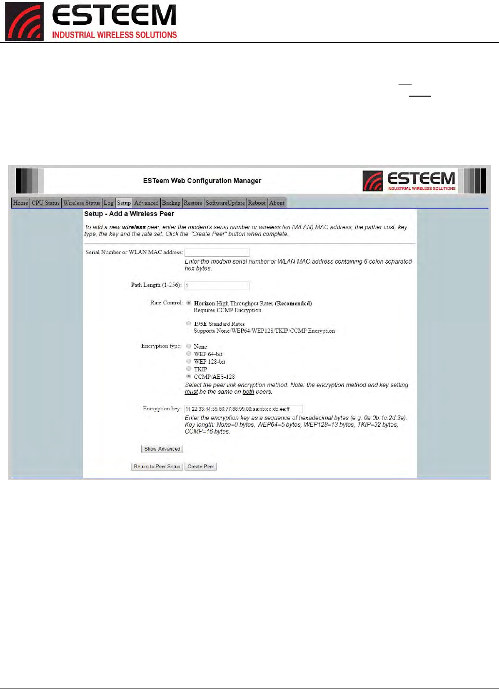
CHAPTER7
BRIDGELINKSANDMESH
Revised: 09 Aug 2016 7-2 ESTeem Horizon Series
YoucanalsoconfiguretheMeshnetworkingdirectlythroughthewebconfigurationsetup(Chapter5).Figure3showsanexample
peertablefromthesetupmenus.FortheHorizontocommunicatewithanotherHorizon,selectYesmustatEnablePeer
Capability.Next,theSerialNumberorWirelessLAN(WLAN)MACaddressofeachHorizonthatwillhavedirectcommunications
mustbeaddedtothePeerList.Finally,enablingthelinkallowsthecorrespondingHorizontobeincludedinthecommunication
routing.Mobileclientsdonotrequireinputintherepeaterpeertable.IfmultipleMeshroutesareconfigured,youwillalsoneed
tosetthevaluesforPriorityandPathLength(explainedinRapidSpanningTreebelow).Formultipleexamplesofrepeater
configurations,pleaserefertoChapter3ofthisuser’smanual.
Figure3:RepeaterConfigurationExample
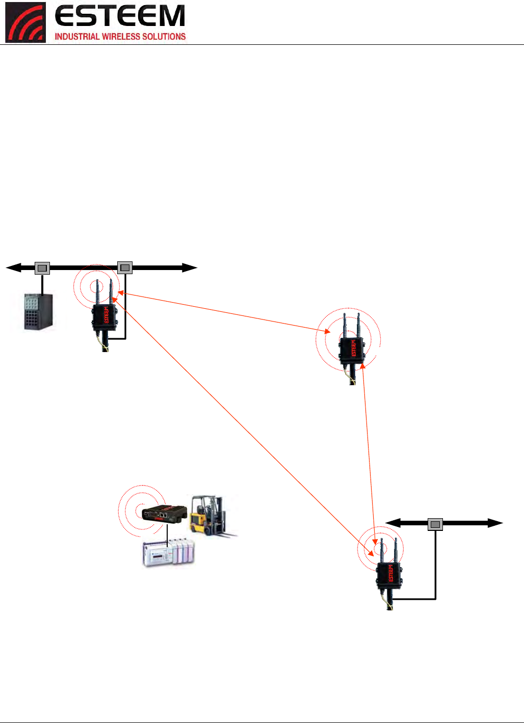
CHAPTER7
BRIDGELINKSANDMESH
Revised: 09 Aug 2016 7-3 ESTeem Horizon Series
RapidSpanningTreeProtocol(RSTP)
TheESTeemHorizonusesstandardEthernetRapidSpanningTreeProtocol(RSTP)todeterminetheradioroutingstructureofthe
wirelessnetwork.TheprimarypurposeofRSTPistomakesurethat“networkloops”arenotcreated.Anetworkloopishaving
twocommunicationpathstothesamedestinationwheretheremotedevicewouldreceivethesamedatamultipletimes.Ifthere
werenowaytocontrolthedataflow,thisdatawouldbeconstantlypassedaroundthisloopcausinga“packetstorm”thatwould
shutdowntheentirenetwork.TheSpanningTreeProtocolwillblockalltheseredundantlinks.
TheRSTPoperationbeginsbydeterminingwhichEthernetdeviceonthenetworkwillbetheRootBridge.AllEthernetnetworks
haveaRootBridgethatisselectedbythelowestMACaddress.AllpathlengthsareevaluatedagainstthisRootBridgedeviceto
determineroutingandwhichpathswillbeblocked.OnawiredEthernetnetwork,thelocationoftheRootBridgeisnotreally
important,butinawirelessnetworkselectionoftheRootBridgeiscriticaltothewirelessnetworkrouting.Let’suseoneofthe
ExamplenetworkdiagramsfromChapter3tocontinuethediscussion(Figure4).
Figure4:ProgrammingExample#1Diagram
Access Point Router
with Repeater
Feature Enabled
10/100BaseT
HUB or Switch
Mobile
PLC
EtherStation
Mode
10/100BaseT
Access Point Bridge
with Repeater
Feature Enabled
Primary Repeater Path
Backup Repeater Path
Access Point Bridge
with Repeater
Feature Enabled
Mobile Vehicle
Single Ethernet Device
Example #4
S/N: 14004
Primary Repeater Path
Plant Network
Large Wired LAN
Example #1
S/N: E-14001
WLAN MAC=00:04:3F:00:09:01
Remote Building
Small Ethernet Wired LAN
Example #3
S/N: E-14003
WLAN MAC=00:04:3F:00:09:10
Stand-Alone Repeater Site
Example #2
S/N: E-14002
WLAN MAC= 00:04:3F:00:09:05
Network
Router
(Required)
CHAPTER7
BRIDGELINKSANDMESH
Revised: 09 Aug 2016 7-4 ESTeem Horizon Series
RSTPPhases
ThefollowingsectionsdescribetheprocessoftheRSTPintheESTeemHorizonashowitwouldhappenintheaboveexample.
LearningPhase‐Onceproperlyconfigured,eachHorizonwillbegintosearchouttheotherHorizonunitsinradiorangethatare
programmedintheAPRepeaterPeertable.AllHorizon’swillcalculatetheirroutestoeveryHorizoninthenetworkbasedupon
thelowest“pathlength”totheRootBridge.Pathlengthisthetotalnumberofwirelesslinks(repeaterpeerlinks)totransmita
packetthroughthewirelessnetworktotheRootBridge.Note:TheRootBridgeinanetworkshouldbetheHorizonwherethe
majorityofthedataflowisprocessed.Ineverywirelessnetworkoftwoormoreradios,theRootBridgeshouldbeuserdefined.
Ifnotdefined,theHorizonwiththelowestMACaddresswillbedesignatedastheRootBridge.
InFigure4,thePlantnetwork(Example1)isthemostlogicallocationfortheRootBridgebasedupontheamountofdataflow.
SettingthissiteastherootbridgeisdiscussedbelowinRootBridge.
BlockingandForwardingPhase–Toensureyoudonothaveanetworkloopsituationduetoredundantpathsinyourwireless
network,theModelHorizonwillrecognizeanddisable(block)oneormoreredundantlinksandprovidebackuplinksshouldthe
primarylinkfail.Thisestablishesawirelessmeshnetworkwithaseriesofforwardinglinks,basedupontheshortestpathlength
totheRootBridge.
Forexample,lookingatFigure4,theRemoteBuildinghastworoutestotheRootBridge(PlantNetwork–Example#1);directlyto
thesiteandthroughtherepeater.Thedirectlinkbetweenthetwositesistheshortestroute(lowestPathLength)andwillbe
selectedastheprimaryrouteunlessoverriddenbymanuallychangingthePathLengthintheconfiguration.
PathLength
IfmorethanonecommunicationpathtotheRootBridgeisfound,theHorizonmustdeterminewhichroutetotakebasedupon
thelowestPathLength.ThedefaultpathlengthtoalllinksintheHorizonnetworkis1.IfthePathLengthsareequalthenthe
lowestMACaddresswilldeterminethepriorityroute.IntheESTeemMeshNetworkwewanttodirectlycontrolalldataflowso
donotwanttheroutestobeautomaticallydetermined.
LookingagainatourExampleinFigure4,ifwemadenochangestothedefaultpathlengthof1(notevaluesinFigure3)thelowest
pathlengthwouldbedirectfromtheRemoteBuildingtotheRootBridge(PlantNetwork).
LinkDescriptionTotalPathLength
DirectfromRemoteBuilding1
RemoteBuildtoRootBridgeThroughRepeater 2(Length1torepeater+Length1toMaster=2)
ToconfiguretheHorizontoselecttherepeaterastheprimaryradiopath,setthepathlengthvalueforthedirectlinkgreaterthan
2(suchasavalueof3)tomakethistheprimaryradiopath.Thelowestpathlengthwillidentifythehighestpriority.TheModel
Horizonwillusethisrouting,butalsoswitchtodirectcommunicationiftherepeaterweretodisappear.
RootBridge
InanyAccessPointRepeaternetworkconsistingofmorethantwosites,oneModelHorizonshouldbedesignatedastheRoot
Bridge.OnlyoneModelHorizoncanbedesignatedastheRootBridgeinagivennetworkandshouldbelocatedwherethemajority
oftheEthernetdataflowisprocessed.ThissitemaybetheMasterlocationinaSCADAnetworkorcouldbeconfiguredata
repeatersite.SelectionisimportantbecauseallModelHorizon’sNOTconfiguredastheRootBridgewillchooseroutingbased
uponthePathLengthtotheRootBridge.IfyouhaveanyquestionastowhichsiteinyourAPRepeaterapplicationshouldbethe
RootBridge,contactESTeemCustomerSupportat509‐735‐9092ore‐mailyourapplicationtosupport@esteem.com.
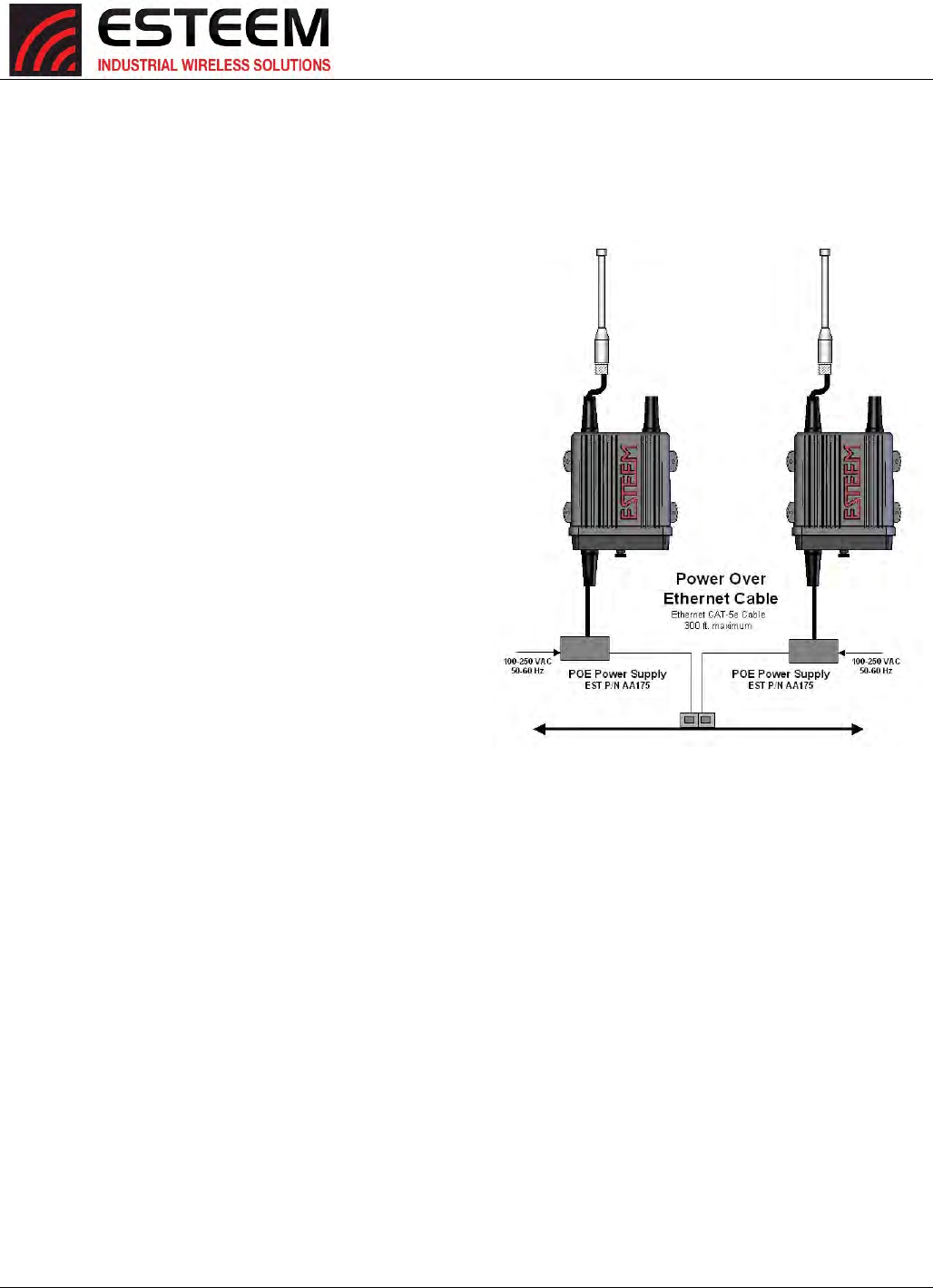
CHAPTER7
BRIDGELINKSANDMESH
Revised: 09 Aug 2016 7-5 ESTeem Horizon Series
TheRootBridgewillbeselectedinoneoftwoways:theRootBridgecanbemanuallyset(recommended)duringtheconfiguration
oftheRepeaterPeertable(Figure3)ortheRootBridgedesignationwilldefaulttothelowestMACaddressofalltheModel
Horizon’sinthenetwork.ThemanualRootBridgeconfigurationislocatedinthe“AdvancedSettings”section.
RedundantBackup
TheESTeemHorizonconfiguredinAccessPointmodewill
automaticallyfunctionasaredundantbackupiftwoHorizonsare
installedatthesamelocation(Figure7).IftwoHorizonsare
connectedtothesameswitch,oneoftheHorizonswillbeBlocked
whentheRapidSpanningTreeProtocoliscompleted.The
networkwillcontinuetousethisrouteuntilanyproblemwiththe
originalModelHorizonisdetectedandthesecondHorizonwill
beginoperationatthatsite.
RedundantMasterConfiguration
TheconfigurationinFigure7willalsoprovidearedundantbackup
fortheMasterSite(RootBridge).ConfigurebothHorizonsasRoot
Bridges(seeabove)givingtheprimaryRootBridgeavalueof1and
thesecondaryRootBridgeavalueof2.
Figure7:RedundantBackupDiagram
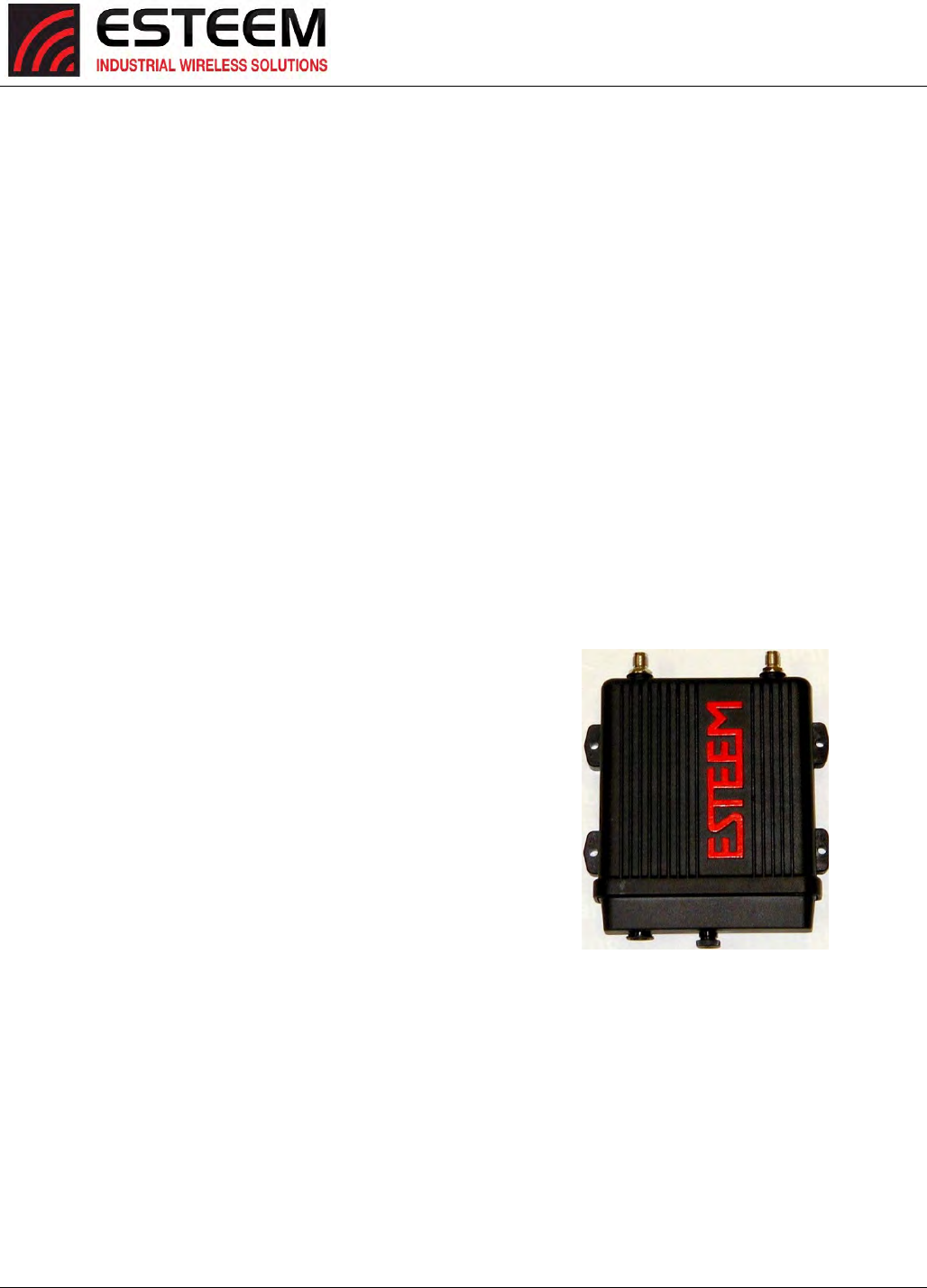
CHAPTER8
ANTENNASETUPS
Revised: 25 Jan 17 8-1 ESTeem Horizon Series
Horizon2.4GHzAntennaandCableConfigurations
ESTeemoffersdifferenttypesofantennasforbothindoorandoutdoorconfigurations.Toreducepotentialradiointerferenceto
otherusers,theantennatypeanditsgainshouldbechosensothattheequivalentisotropicallyradiatedpower(e.i.r.p.)isnot
morethanthatpermittedforsuccessfulcommunication.
ThisradiotransmitterESTeemHorizon2.4GHz(HVIN:216AN)hasbeenapprovedbyIndustryCanadatooperatewiththeantenna
typeslistedbelowwiththemaximumpermissiblegainandrequiredantennaimpedanceforeachantennatypeindicated.Antenna
typesnotincludedinthislist,havingagaingreaterthanthemaximumgainindicatedforthattype,arestrictlyprohibitedforuse
withthisdevice.
LepresentemetteurradioESTeemHVIN:216ANaeteapprouveparIndustrieCanadapourfonctionneraveclestypesd'antenne
enumeresci‐dessousetayantungainadmissiblemaximaletl'impedancerequisepourchaquetyped'antenne.Lestypesd'antenne
noninclusdanscetteliste,oudontlegainestsuperieuraugainmaximalindique,sontstrictementinterditspourl'exploitationde
l'emetteur.
Warning:OnlythetestedcablelengthsandantennasprovidedbyESTeemmeettheFCCmaximumpeakoutputpower
requirements.Anyothercombinationofantennasorcoaxcablesisnotauthorized.Thisdevicehasbeendesigned
tooperateinapolemountconfigurationwiththeantennaslistedbelow,havingamaximumgainof6dBinamulti‐
pointsystemor15dBinapointtopointnetwork.Antennasnotincludedinthislistorhavingagaingreater6dBin
amulti‐pointsystemor15dBinapointtopointnetworkarestrictlyprohibitedforusewiththisdevice.Therequired
antennaimpedanceis50ohms.
PartNumber:AA20DMEg
Omni‐directionaldirectmountantenna,5dBigain.
Indoorandoutdoorapplications.
Theremustbeaminimumseparationdistanceof24
cm.fromtheantennatotheuser.SeeWarnings.
PartNumber:AA203Eg
Directionalpolemountantenna,6dBigainwith3‐ft.
integralfeedlineandconnector.
Pointtopointandpointtomulti‐pointoutdoor
applications.
AntennaportBisnotusedinthisconfiguration.
Theremustbeaminimumseparationdistanceof24
cm.fromtheantennatotheuser.SeeWarnings.
PartNumber:AA204Eg.1
Directionalpolemountantenna,15dBigainwith3‐ft.
integralfeedlineandconnector.
Pointtopointapplicationsonly.
MaximumOutputPowerof250mWatts(PowerLevel=
LowPower)
AntennaportBisnotusedinthisconfiguration.
Theremustbeaminimumseparationdistanceof50
cm.fromtheantennatotheuser.SeeWarnings.
Transmit/Receive
A
ntenna Port 1 Receive Only
Antenna Port 2
Warnings:
Only pre-made coax cables from the factory used in
conjunction with either the AA203Eg or AA204Eg.1
directional antennas meet all FCC Section 15.247(b)
EIRP maximum power requirements.
Use of the AA204Eg.1, directional antenna is limited to
fixed point to point applications only. In accordance FCC
Section 15.247(b)iii, this antenna must be professionally
installed. The installer must ensure the system is used
exclusively for fixed, point-to-point applications and the
ESTeem Horizon is set for 0.25 Watts output power
(Power Level = Min).
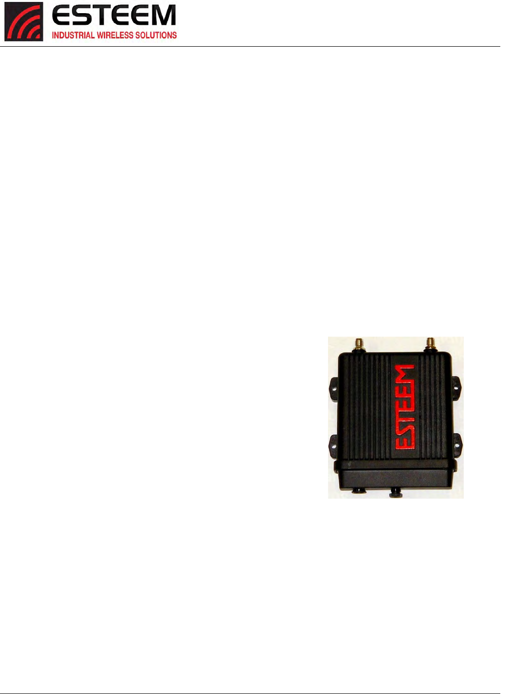
CHAPTER8
ANTENNASETUPS
Revised: 25 Jan 17 8-2 ESTeem Horizon Series
Horizon900MHzAntennaandCableConfigurations
ESTeemoffersdifferenttypesofantennasforbothindoorandoutdoorconfigurations.Thisdevicehasbeendesignedtooperate
withtheantennaslistedbelow,andhavingamaximumgainof7dB.Antennasnotincludedinthislistorhavingagaingreater
than7dBarestrictlyprohibitedforusewiththisdevice.Therequiredantennaimpedanceis50ohms.
ThisradiotransmitterESTeemHorizon900MHz(HVIN:216AD)hasbeenapprovedbyIndustryCanadatooperatewiththe
antennatypeslistedbelowwiththemaximumpermissiblegainandrequiredantennaimpedanceforeachantennatypeindicated.
Antennatypesnotincludedinthislist,havingagaingreaterthanthemaximumgainindicatedforthattype,arestrictlyprohibited
forusewiththisdevice.
LepresentemetteurradioESTeemHVIN:216ADaeteapprouveparIndustrieCanadapourfonctionneraveclestypesd'antenne
enumeresci‐dessousetayantungainadmissiblemaximaletl'impedancerequisepourchaquetyped'antenne.Lestypesd'antenne
noninclusdanscetteliste,oudontlegainestsuperieuraugainmaximalindique,sontstrictementinterditspourl'exploitationde
l'emetteur.
Warning:OnlythetestedcablelengthsandantennasprovidedbyESTmeettheFCCandDOCmaximumpeakoutputpower
requirements.Anyothercombinationofantennasorcoaxcablesisnotauthorized.Toreducepotentialradiointerferenceto
otherusers,theantennatypeanditsgainshouldbesochosenthattheequivalentisotropicallyradiatedpower(e.i.r.p.)isnot
morethanthatpermittedforsuccessfulcommunication.
PartNumber:AA20DMs
Omni‐directionaldirectmountantenna,2dBigain.
Indoorandoutdoorapplications.
Theremustbeaminimumseparationdistanceof23
cm.fromtheantennatotheuser.SeeWarnings.
PartNumber:AA20Es900
Omni‐directionalexternalpolemountantenna,7dBi
gainwith3‐ft.integralfeedlineandconnector.
Outdoorapplications.
Theremustbeaminimumseparationdistanceof
23cm.fromtheantennatotheuser.SeeWarnings.
PartNumber:AA203Es900
Directionalpolemountantenna,7dBigainwith3‐ft.
integralfeedlineandconnector.
Pointtopointandpointtomulti‐pointoutdoor
applications.
Theremustbeaminimumseparationdistanceof23
cm.fromtheantennatotheuser.SeeWarnings.
Notes:
Antenna Port A is a transmit and receive port for use in all
applications.
Antenna Port B is a receive only port and is used for dual
diversity antennas applications only. This port is not used
for point to point applications.
Warnings:
Only pre-made coax cables from the factory used in
conjunction with either the AA20Es900 omni-directional
and AA203Es900 directional antennas meet all FCC
Section 15.247(b) EIRP maximum power requirements.
Transmit/Receive
A
ntenna Port 1 Receive Only
Antenna Port 2
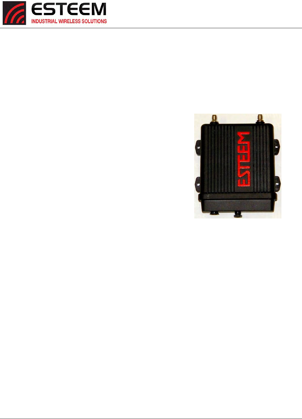
CHAPTER8
ANTENNASETUPS
Revised: 25 Jan 17 8-3 ESTeem Horizon Series
Horizon4.9GHzAntennaandCableConfigurations
ESTeemoffersdifferenttypesofantennasforindoor,outdoorandmobileconfigurations.
PartNumber:AA191Ep
Omni‐directional,vehiclemount,5.5dBigainantenna.
Mobilevehiclemountapplications.
TheAA191Epantennamustbeinstalledtoprovidea
separationdistanceofatleast20cmfromallpersons
andmustnotbeco‐locatedoroperatingin
conjunctionwithanyotherantennaortransmitter.
PartNumber:AA20DMEp
Omni‐directionaldirectmountantenna,5dBigain.
Indoorandoutdoorapplications.
TheAA20DMpantennamustbefixed‐mountedon
outdoorpermanentstructureswithaseparation
distanceofatleast20cmfromallpersonsduring
normaloperationandmustnotbeco‐locatedor
operatinginconjunctionwithanyotherantennaor
transmitter.
PartNumber:AA20Ep
Omni‐directionalpolemountantenna,10dBigain
AntennaportBisnotusedinthisconfiguration.
TheAA20Epantennamustbefixed‐mountedon
outdoorpermanentstructureswithaseparation
distanceofatleast20cmfromallpersonsduring
normaloperationandmustnotbeco‐locatedor
operatinginconjunctionwithanyotherantennaor
transmitter.
PartNumber:AA204Ep
Directionalpolemountantenna,21dBigainwith3‐ft.
integralfeedlineandconnector.
AntennaportBisnotusedinthisconfiguration.
TheAA204Epantennamustbefixed‐mountedon
outdoorpermanentstructureswithaseparation
distanceofatleast60cmfromallpersonsduring
normaloperationandmustnotbeco‐locatedor
operatinginconjunctionwithanyotherantennaor
transmitter.
Transmit/Receive
A
ntenna Port 1 Receive Only
Antenna Port 2
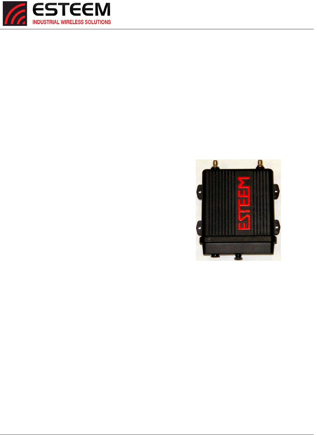
CHAPTER8
ANTENNASETUPS
Revised: 25 Jan 17 8-4 ESTeem Horizon Series
Horizon5.8GHzAntennaandCableConfigurations
ESTeemoffersdifferenttypesofantennasforbothindoorandoutdoorconfigurations.Thisdevicehasbeendesignedtooperate
withtheantennaslistedbelow,andhavingamaximumgainof22dBi.Antennasnotincludedinthislistorhavingagaingreater
than22dBiarestrictlyprohibitedforusewiththisdevice.Therequiredantennaimpedanceis50ohms.
Warning:ThisradiotransmitterESTeemHorizon5.8GHzcontainsFCCIDTV7R11E5HNDandonlythetestedcablelengthsand
antennasprovidedbyESTmeettheFCCmaximumpeakoutputpowerrequirements.Anyothercombinationofantennasor
coaxcablesisnotauthorized.Toreducepotentialradiointerferencetootherusers,theantennatypeanditsgainshouldbeso
chosenthattheequivalentisotropicallyradiatedpower(e.i.r.p.)isnotmorethanthatpermittedforsuccessfulcommunication.
PartNumber:AA20DMEa
Omni‐directionaldirectmountantenna,4.5dBigain.
Indoorandoutdoorapplications.
Theremustbeaminimumseparationdistanceof23
cm.fromtheantennatotheuser.SeeWarnings.
PartNumber:AA20Ea
Omni‐directionalexternalpolemountantenna,10dBi
gainwith18‐inchintegralfeedlineandconnector.
Outdoorapplications.
Theremustbeaminimumseparationdistanceof23
cm.fromtheantennatotheuser.SeeWarnings.
PartNumber:AA205Ea
Directionallinearpanel,polemountantenna,22dBi
gainwith18‐inchintegralfeedline,bandpassfilterand
connector.
Pointtopointandpointtomulti‐pointoutdoor
applications.
Theremustbeaminimumseparationdistanceof50
cm.fromtheantennatotheuser.SeeWarnings.
Transmit/Receive
A
ntenna Port 1 Transmit/Receive
Antenna Port 2
Warnings:
Only pre-made coax cables from the factory used in
conjunction with either the omni-directional and
directional antennas meet all FCC Section 15.247(b)
EIRP maximum power requirements.
To comply with the FCC exposure compliance
requirements, a separation distance of at least 20 cm
must be maintained between the antenna and all
persons.
CHAPTER8
ANTENNASETUPS
Revised: 25 Jan 17 8-5 ESTeem Horizon Series
WEATHERPROOFINGCOAXCONNECTIONS
1.Lightlycoatthethreadsoftheconnectorswithsiliconelubricantpriortoassembly(SeeNote1)andhandtighten.Make
suretousethesiliconsparinglysowhenassembled,anyexcessdoesnotgetoncenterconductor.Careshouldbetaken
nottogetanylubricantonthecenterconductor.
2.Wraptheconnectorassemblywithanon‐adhesivesiliconetape,ESTpartnumberAA243,forweatherproofing(SeeNote
2andinstructionsbelow).
a) Cleansurfacetobewrapped.Cutofflengthtobeused.
b) Peelbackashortlengthofprotectivefilm.Keeptapecleananddry.
c) Beginwithonecompleteoverlapoftapeontoitself.
d) STRETCHCoaxWrapwhilecontinuingtowrapobjectwith“half‐laps”,removingclearfilmasyougo(Figure1).For
greaterpressureresistance,use2ormoretightlywrappedlayers.
e) Endoftapeatfinalwrapshouldbecompletelypositionedontoitself.
Note:CoaxWrap’sbondbeginstocureimmediatelyuponcontactwithitself.Repositioningor
removalisnotrecommendedafter2minutesofwrapping.
3.Applyanelectricalcoating(sealingagent),overthevaporbarrierpatchforadded
protection(SeeNote3).
NOTES:
1.DowCorningRTV‐3140orequivalent.
2.CoaxWrap,CW10Borequivalent.
3.SCOTCHKOTE,3‐MCompany,orequivalent.
ANTENNADIVERSITY
ThedualdiversityantennaconfigurationontheHorizonallowstheradiotooperatemoreefficientlyinareaswithhighreflections
(suchasindoorsorinacity)withoutdirectlineofsight(LOS)betweentheantennas.Oneofthemostdifficultconditionstocontrol
inaradiosystemistheeffectofadestructivereflectedradiosignalcalledmutipathing.Multipathingoccurswhenwavesemitted
bythetransmittertravelalongadifferentpathandinterferedestructivelywithwavestravelingonadirectline‐of‐sitepath.The
phenomenonoccursbecausewavestravelingalongdifferentpathsmaybecompletelyoutofphasewhentheyreachtheantenna,
therebycancelingeachotherout.Thedualdiversityantennaconfigurationplacesaphysicaldistancebetweentheantennas
whereonereflectedsignalwillbeoutofphase,butthesecondwillbenot.TheESTeemHorizonwillsamplebothantennasand
selectthebestreceivesignal.BothantennaportsareactivebydefaultintheHorizonseries.
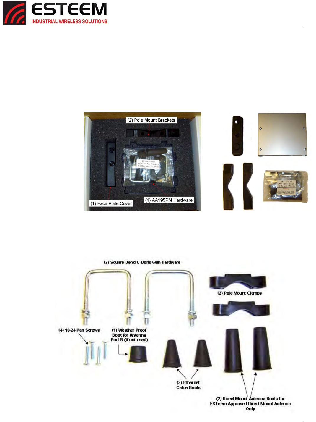
CHAPTER8
ANTENNASETUPS
Revised: 25 Jan 17 8-6 ESTeem Horizon Series
AssemblingTheAA195PMTwoHoleOutdoorPoleMountingKit
TheAA195PMmountingkitcontainseverythingrequiredforpolemountingandweatherproofingtheESTeemHorizonforoutdoor
installations.TheHorizonwithAA195PMmountingkitcanbedirectlymountedtoaroundpolefrom1.25”toadiameterof2.25”
OD.Anymountingstructuregreaterthan2”requireshoseclampstrappingrunthroughthePoleMountBrackets.Themounting
kitrequiresthefollowingassembly:
1. IfyoupurchasedanAA195PMmountingkitwithyourHorizon,thekitwillbepackedinthesamepackingboxastheESTeem
(Figure4).
2. Removeandinventorythe
two(2)PoleMounting
Brackets,one(1)Two‐Hole
FacePlateCover(with
singleportcoverinstalled),
one(1)HeatShieldand(1)
AA195PMHardwarebag
fromthepackingbox
(Figure4).Reportany
missingordamageditems
toESTeemCustomer
Support(Phone509‐735‐
9092)assoonaspossible
forreplacement.
3. InventorytheAA195PM
Hardwarebagforallthe
componentslistedin
Figure5.
Figure4:PacketBoxContents
Figure5:AA195PMHardwareContents
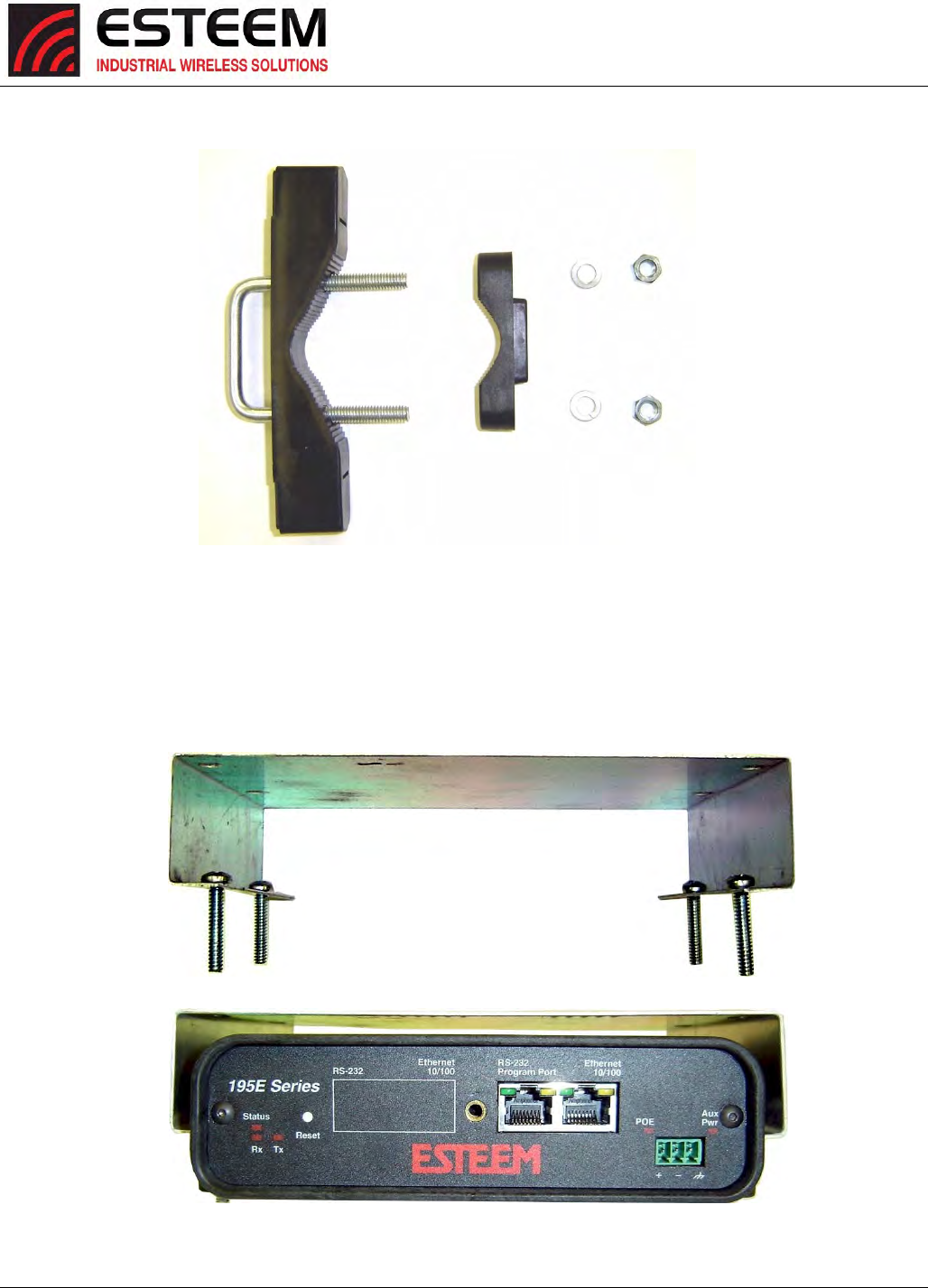
CHAPTER8
ANTENNASETUPS
Revised: 25 Jan 17 8-7 ESTeem Horizon Series
4. AssemblethetwoPoleMountingBracketswiththeincludedU‐bolts,hardwareandPoleMountClamps.ReferenceFigure6.
5. Placethefoursupplied10‐24x1”PhillipsPanHeadscrewsthroughthemountingholesoftheHeatShieldandattachtothe
topoftheESTeemHorizon(Figure7).
6. AttachthetwoPoleMountingBracketstotheESTeemHorizonwiththe10‐24x1”PhillipsPanHeadscrewsthroughthetop
oftheheatshield.ReferenceFigure8(HeatShieldremovedfordetail).
Figure6:PoleMountAssembly
Figure7:HeatShieldAttachment
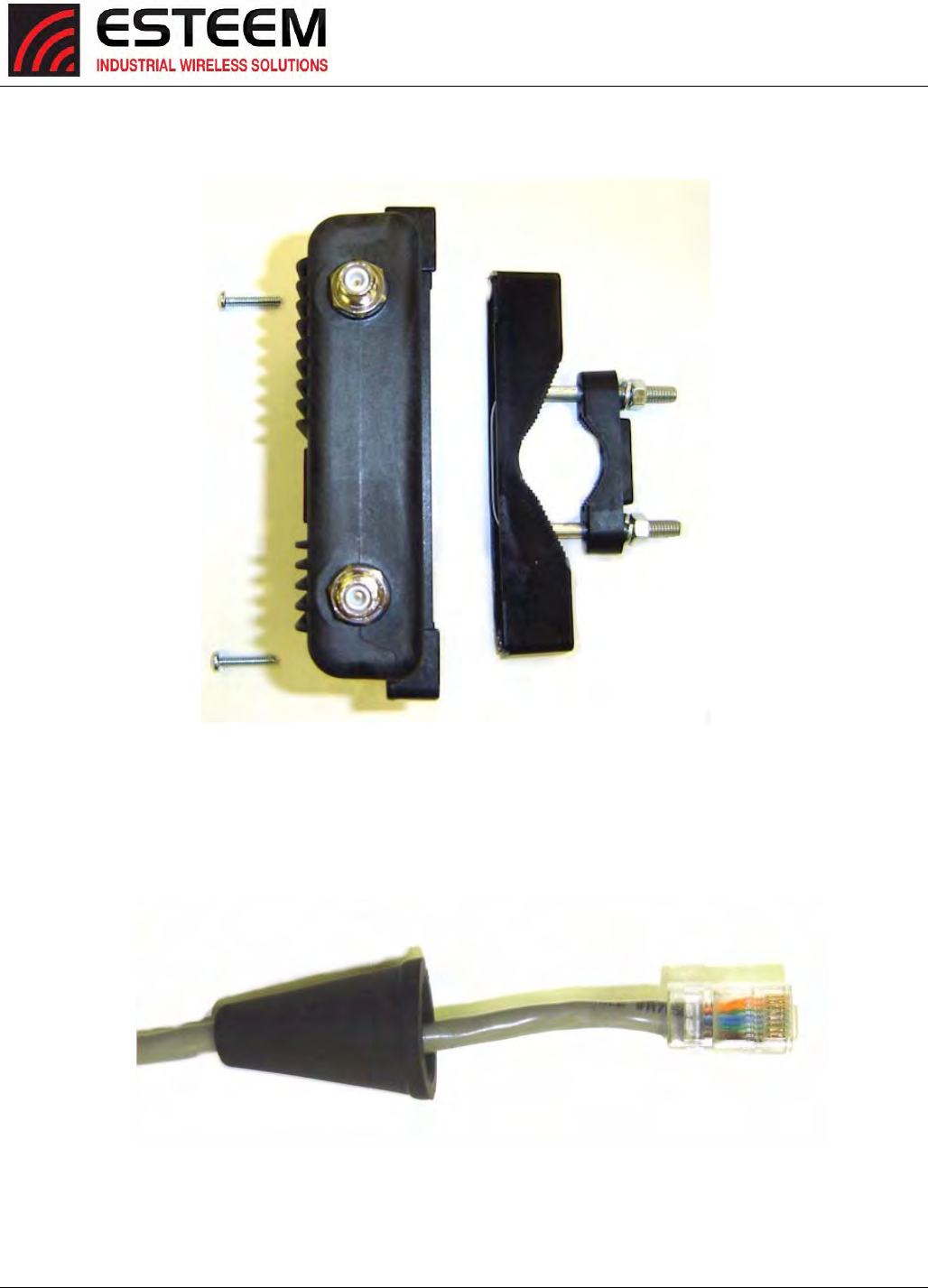
CHAPTER8
ANTENNASETUPS
Revised: 25 Jan 17 8-8 ESTeem Horizon Series
7. AssembletheoutdoorratedCAT‐5eEthernetcable(NotProvided)withthesuppliedEthernetCableBoot(Figure9).
Figure8:PoleMountConnectiontoCase
(HeatShieldRemovedforDetail)
Ethernet Cable Boot
Figure9:EthernetCableAssembly
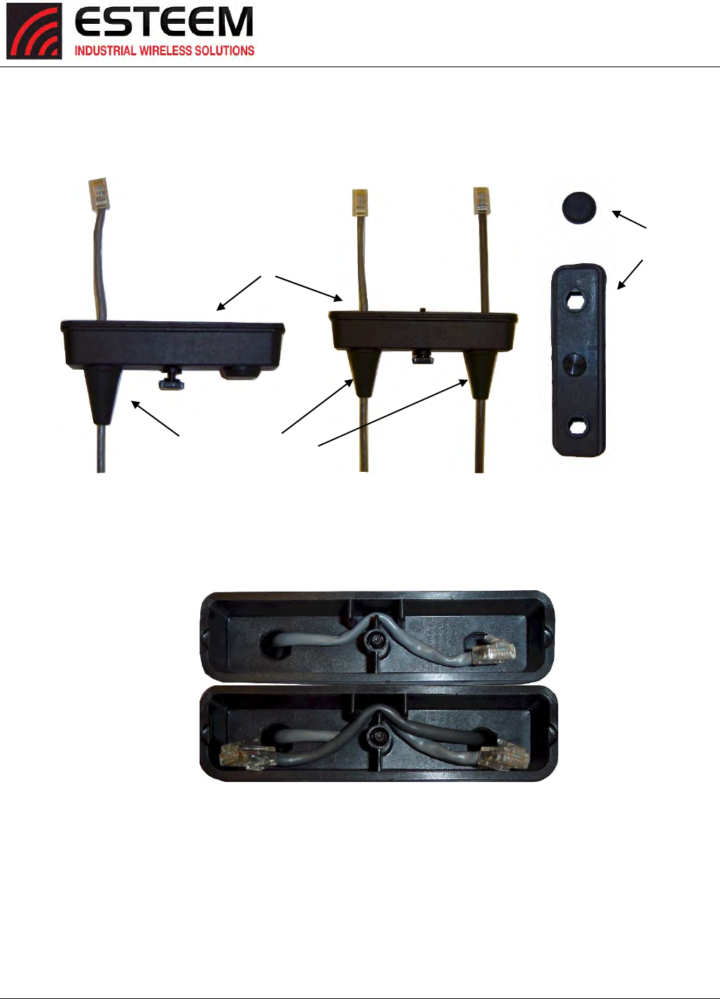
CHAPTER8
ANTENNASETUPS
Revised: 25 Jan 17 8-9 ESTeem Horizon Series
8. FeedtheCAT‐5eEthernetconnector(s)throughtheFacePlateCoverandsecuretheEthernetCableBoottothecover.
ReferenceFigure10.
NOTE:TheEthernetcablebootmustbeinstalledbeforetheRJ‐45endisinstalled.IfusingtheESTeemAA09.1outdoor
Ethernetcable,verifythattheEthernetcablebootendisroutedtowardtheESTeemHorizon.
9. RoutetheCAT‐5eEthernetcablethroughthemoldedstrain‐relieffinsintheFacePlateCover(Figure11)tosecurethecable
andprovidestrain‐relieffortheconnector.IfasecondEthernetcableisinstalled,removethesecondportcoverandroute
cable.
10. PlugtheCAT‐5eEthernetcabletotheHorizon’sEthernetportandsecuretheFacePlateCoverwiththeattachedthumbscrew.
VerifythattheweatherproofsealontheFacePlateCoverissealedagainsttheouterrimoftheHorizon.ReferenceFigure12.
11. AttachtheantennaconnectorbootsasshowinFigure13foreitherdualattachedantennasorexternalantennas.Youare
nowreadytomounttheESTeemHorizon
Figure11:FacePlateCoverStrainRelief
Figure10:EthernetCableRouting
Face Plate Cover
Ethernet Cable Boots
Second Port Cover
Remove for 2nd Cable
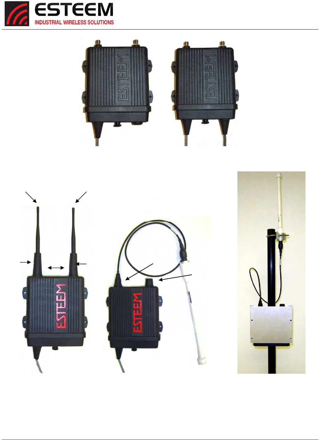
CHAPTER8
ANTENNASETUPS
Revised: 25 Jan 17 8-10 ESTeem Horizon Series
Caution:OutdoormountingoftheHorizonrequirestheuseofweatherproofboots.Improperinstallationcould
resultinradiofailure.
Caution:AlwaysmounttheHorizonverticallywiththeantennaportsontop.
Figure12:FacePlateCoverInstalledonESTeem
Figure13:CompletedAA195PMMounts
Direct Mount
Antenna Boots
Port 1
EST Approved Direct Mount
Antenna Only
Port 2
EST Approved External
Antenna With Factory
Installed Boot
Weather Proof Boot
NOTE: Remove Plastic
Connector Cover
Before Installation
Face Towards
The South
(North America)
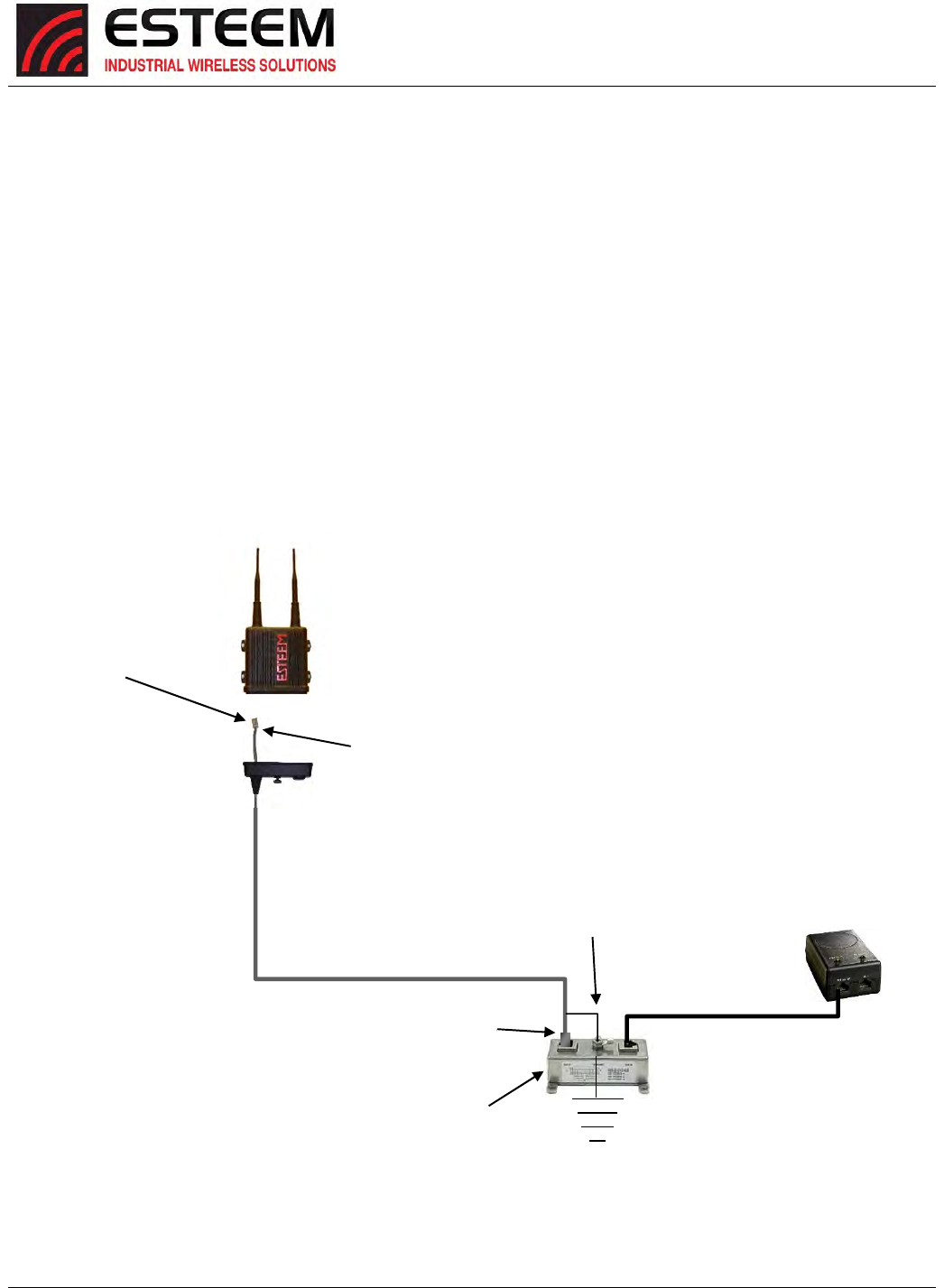
CHAPTER8
ANTENNASETUPS
Revised: 25 Jan 17 8-11 ESTeem Horizon Series
HorizonPoleMountGroundingProcedures
MountingtheHorizonseriesradiomodemoutdoorsrequirespropergroundingprocedurestopreventdamagetoboththeradio
hardwareandtheconnectedEthernetandSerialperipherals.ThecaseontheHorizonserieswirelessmodemiselectrically
conductive,buttheAA195PoleMountkitprovidesisolationfromtheconnectedstructure.TobringtheHorizoncasetoaground
potentialwithEarthgroundandeliminateanystaticbuilduponthecaseitself,theshieldontheEthernetcableisusedtoprovide
thegroundconnection.
OutdoorEthernetCable
AcriticalcomponentofthisgroundingprotectionsystemistheESTeemAA09.1outdoor,shieldedCAT‐5EEthernetcable.This
cableprovidesthree,necessaryelements;Ethernetdata,DCPoweroverEthernet(PoE)applications,andagroundfromthe
HorizoncasetotheAA166surgeprotector.TheEthernetcableisoutdoorratedandprotectedfromUVbreakdown.
Installation
ThefollowingdiagramoutlinesallthecriticalcomponentsandconnectionsintheHorizonseriessystem.TheEarthground
connectiontothesurgeprotectormustbeinstalledtocomplywithlocalElectricalcoderequirements.
Figure14:PoleMountInstallationDiagram
ESTeem Horizon
Series Wireless Modem
ESTeem AA09.1
Outdoor, Shielded
CAT-5E Cable
(300 ft. maximum)
Metal RJ-45 Hood
(Amp 5-569530-3)
Drain Wire Soldered
To Metal RJ-45 Hood
Drain Wire With
Ring Terminal Connected
to Ground Lug
Approved Earth
Ground Connection
AA166 Ethernet
Surge Protection
Ethernet Patch Cable
(AA09.2)
Power Over Ethernet
Supply
(AA175)
Metal RJ-45 Hood
(Amp 5-569530-3)
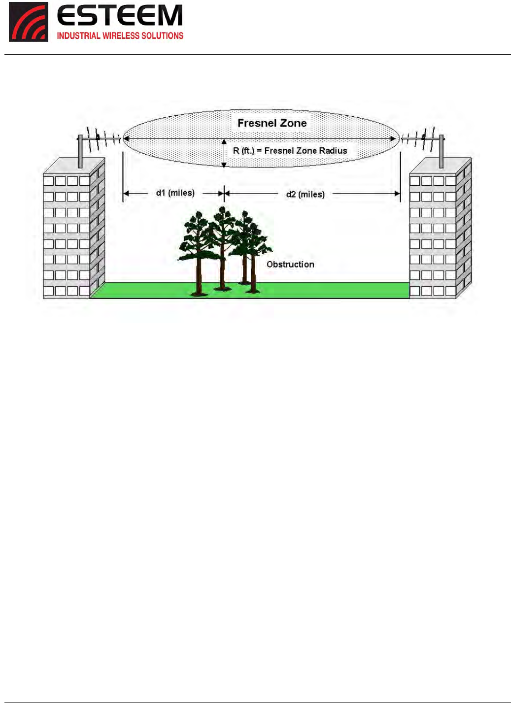
CHAPTER8
ANTENNASETUPS
Revised: 25 Jan 17 8-12 ESTeem Horizon Series
FresnelZone
TheFresnelzoneshowstheellipsoidspreadoftheradiowavesaroundthevisualline‐of‐sightaftertheyleavetheantenna(see
Figure15).Thisareamustbeclearofobstructionsorthesignalstrengthwillbereducedduetosignalblockage.Typically,20%
FresnelZoneblockageintroduceslittlesignallosstothelink.Beyond40%blockage,signallosswillbecomesignificant.This
calculationisbasedonaflatearth.Itdoesnottakeintoaccountthecurvatureoftheearth.ItisrecommendedforRFpathlinks
greaterthan7milestohaveamicrowavepathanalysisdonethattakesthecurvatureoftheearthandthetopographyofthe
terrainintoaccount.
FresnelZoneRadius=72.1SQRT[(d1d2)/(F(d1+d2)]
Units
FresnelZoneRadiusinfeet.
d1andd2instatuemiles
FinGHz
Figure15:FresnelZoneDiagram

APPENDIXA
LICENSINGINFORMATION
Revised: 25 Jan 17 APX A-1 ESTeem Horizon Series
InformationtoUsers
TheequipmenthasbeentestedandfoundtocomplywiththelimitsforboththeFCCClassBdigitaldevice(pursuanttoPart15
oftheFCCrules)andIndustryCanada(IC)CANICES‐3(B)/NMB‐3(B).
FCCStatement
Operationissubjecttothefollowingtwoconditions:(1)Thisdevicemaynotcauseharmfulinterference,and(2)thisdevice
mustacceptanyinterferencereceived,includinginterferencethatmaycauseundesiredoperation.
Caution:ChangesormodificationstothisequipmentnotexpresslyapprovedbyESTeemWirelessModemsforcompliancecould
voidtheuser'sauthoritytooperatetheequipment.
ICStatement
“ThisdevicecomplieswithIndustryCanadalicence‐exemptRSSstandard(s).Operationissubjecttothefollowingtwo
conditions:(1)thisdevicemaynotcauseinterference,and(2)thisdevicemustacceptanyinterference,including
interferencethatmaycauseundesiredoperationofthedevice.”
“CetappareilestconformeavecIndustrieCanadaexemptsdelicencestandardRSS(s).Sonfonctionnementestsoumisaux
deuxconditionssuivantes:(1)cetappareilnedoitpasprovoquerd'interférenceset(2)cetappareildoitacceptertoute
interférence,ycompriscellespouvantcauserunmauvaisfonctionnementdel'appareil.”
EmissionsInformation
Horizon2.4GHz(Model216An)
HVIN:216AN
DirectSequence/OFDMSpreadSpectrumDevice
(USA)FCCID:ENPHZN216AN
(Canada)ICNo:2163A‐216AN
Horizon900MHz(Model216Ad)
HVIN:216AD
DirectSequence/OFDMSpreadSpectrumDevice
(USA)FCCID:ENPHZN216AD
(Canada)ICNo:2163A‐216AD
Horizon4.9GHz(Model216Ap)
DirectSequence/OFDMSpreadSpectrumDevice
(USA)FCCID:ENPHZN216AP
Horizon5.8GHz(Model216Aa‐lp)
OFDMSpreadSpectrumDevice
(USA)FCCID:TV7R11E5HND
APPENDIXA
LICENSINGINFORMATION
Revised: 25 Jan 17 APX A-2 ESTeem Horizon Series
FEDERALCOMMUNICATIONSCOMMISSIONFIELDOFFICES
ALASKA
1011E.TudorRd.
Rm240Box2955
Anchorage,AK99510
CALIFORNIA
InterstateOfficePark
4542RuffnerSt.,Room370
SanDiego,CA92111‐2216
LosAngelesOffice(LA)
CeritosCorporateTower
18000StudebakerRd.,Room660
Cerritos,CA90701‐3684
SanFranciscoOffice(SF)
5653StoneridgeDrive,Suite105
Pleasanton,CA94588‐8543
COLORADO
DenverOffice(DV)
215S.WadsworthBlvd.,Suite303
Lakewood,CO80226‐1544
FLORIDA
919FederalBldg
51SEFirstAve.
Miami,FL33130
TampaOffice(TP)
2203N.LoisAve.,Room1215
Tampa,FL33607‐2356
GEORGIA
AtlantaOffice(AT)
3575KogerBlvd.,Suite320
Duluth,GA30096‐4958
HAWAII
7304PrinceKuhi
FederalBuilding
Honolulu,HI
ILLINOIS
ChicagoOffice(CG)
ParkRidgeOfficeCtr.,Room306
1550NorthwestHighway
ParkRidge,IL60068‐1460
LOUISIANA
NewOrleansOffice(OR)
2424EdenbornAve.Suite460
Metarie,LA70001
MARYLAND
1017Geo.Fallon
Building31
HopkinsPlaza
Baltimore,MD
MASSACHUSETTS
BostonOffice(BS)
1BatterymarchPark
Quincy,MA02169‐7495
MICHIGAN
DetroitOffice(DT)
24897HathawayStreet
FarmingtonHills,MI48335‐1552
MINNESOTA
691FederalBuilding
316NRobertSt.
St.Paul,MN
MISSOURI
KansasCityOffice(KC)
520NEColbernRoad
SecondFloor
Lee’sSummit,MO64086
NEWYORK
1307FederalBuilding
111W.Huron
Buffalo,NY14202
NEWYORK
NewYorkOffice(NY)
201VarickStreet,Suite1151
NewYork,NY10014‐4870
OREGON
1782FederalBuilding
1220SW3rdAvenue
Portland,OR97204
PENNSYLVANIA
PhiladelphiaOffice(PA)
OneOxfordValleyOfficeBld.
Room404
2300E.LincolnHwy
Langhorne,PA19047‐1859
PUERTORICO
747FederalBuilding
CarloChardonAve.
HatoRey,PR00918
TEXAS
DallasOffice(DL)
9330LBJFreeway,Room1170
Dallas,TX75243‐3429
5636FederalBuilding
515RuskAvenue
Houston,TX77002
WASHINGTONDC
ColumbiaOffice(CF)
9300EastHamptonDrive
CapitolHeights,MD20743
WASHINGTON
SeattleOffice(ST)
11410NE122ndWay
Room312
Kirkland,WA98034‐6927
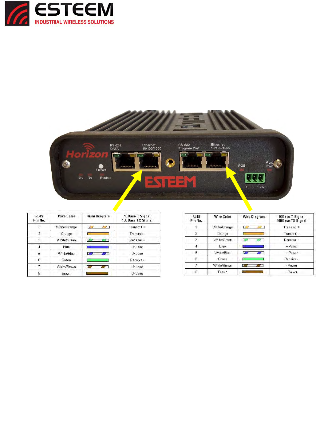
APPENDIXB
INTERFACEPORTS
Revised: 30 Jan 17 APX B-1 ESTeem Horizon Series
ETHERNETINTERFACE
TheESTeemHorizon’sEthernetPortisaFullandHalf‐DuplexAuto‐negotiationinterfacesupporting10Mbps,100Mbpsand1Gbps
(10/100/1000BaseT).TheEthernetportiscompliantwithIEEE802.3at‐2009PowerOverEthernetPlus(PoE+)toprovideboth
dataandpoweroverthesameCAT‐5EgradeEthernetcable.TheportiscompatiblewithTIA/EIA‐568Bcableconfiguration(Figure
1).
AsecondEthernetportisincludedwiththeESTeemHorizon.ThissecondEthernetportcanbeconfiguredtobridgetotheprimary
EthernetportorconfiguredtocommunicateontheWirelessorEthernetsideoftheHorizoninroutermode.
Figure1:EthernetPinLayout
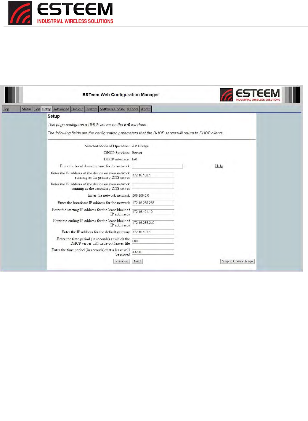
APPENDIXB
INTERFACEPORTS
Revised: 30 Jan 17 APX B-2 ESTeem Horizon Series
CONFIGURINGDHCPSERVER
TheESTeemHorizonEthernetportsupportsbothclientandserverDynamicHostConfigurationProtocol(DHCP).Figure2shows
theDHCPhostconfigurationscreenthatwillbeshownifDHCPserverisselectedinthesetupscreens.Enterthevaluesthatmatch
theDHCPconfigurationforyournetwork.
Figure2:DHCPServerConfiguration
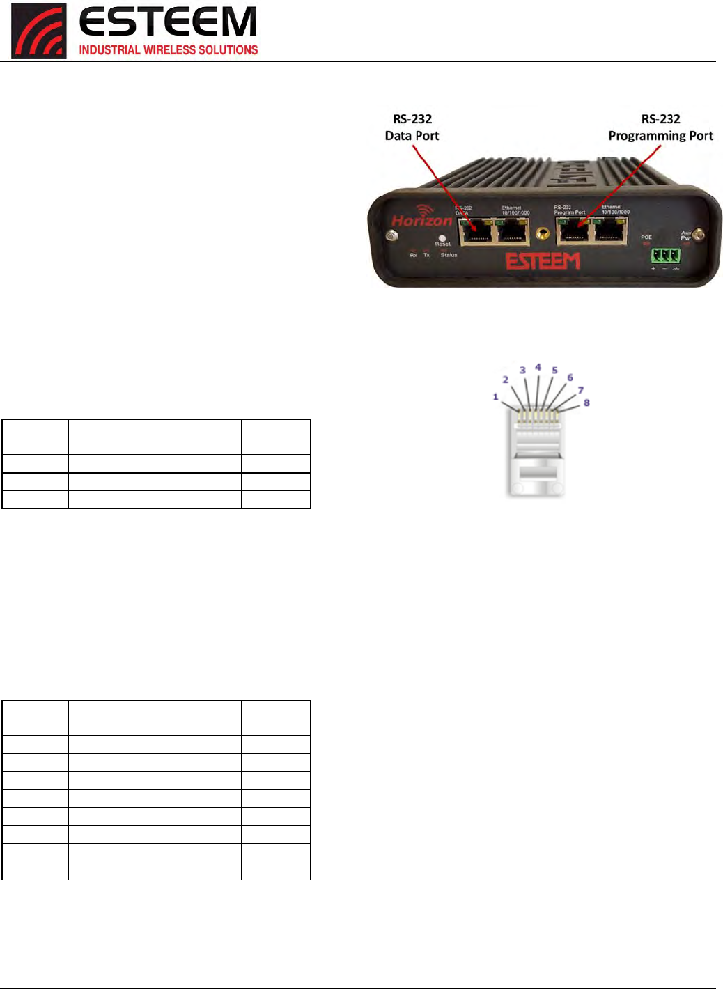
APPENDIXB
INTERFACEPORTS
Revised: 30 Jan 17 APX B-3 ESTeem Horizon Series
RS‐232CProgrammingPortConfiguration
TheESTeemHorizonusesaproprietaryRS‐232Cinterfaceina
RJ‐45connectoronthefrontpanel.TointerfacetheHorizonto
theserialportonthecomputer,youneedESTeemcableAA0621
thatcombinesastandardEthernetpatchcabletoa9‐pinFemale
adapter.
TheRS‐232ProgrammingPortontheESTeemHorizoncanbe
usedtoaccesstheconfigurationmenuintheESTeemforsystem
andnetworkconfiguration.TheESTeemcommunicationsport
operatesat38,400bps,NoParity,8DataBitsand1StopBit
(38,400,N,8,1).Configureyourterminalprogramtomatchthese
settings.
RS‐232ProgrammingPortPin‐OutTable
ESTeemModelAA0621
RS‐232CPortPin‐OutTable
RJ‐45Pin
No.
Function
DB‐9
PinNo.
4SignalGround(GND)5
5ReceiveData(RxD)2
6TransmitData(TxD)3
RS‐232CDataPortConfiguration
TheESTeemHorizonhasanRS‐232CdatainterfaceinaRJ‐45connectoronthefrontpanel.SeeChapter6forfurtherinformation
onserialdataportconfiguration.TointerfacetheHorizontotheserialportonthecomputer,youneedserialcablewiththe
followingpin‐out:
ESTeemModelAA0621
RS‐232CPortPin‐OutTable
RJ‐45Pin
No.
Function
DB‐9
PinNo.
1DataSetReady(DSR)6
2DataCarrierDetect(DCD)1
3DataTerminalReady(DTR)4
4SignalGround(GND)5
5ReceiveData(RxD)2
6TransmitData(TxD)3
7CleartoSent(CTS)8
8RequesttoSent(RTS)7
HorizonSerialPortInterface
EthernetPin‐out
APPENDIXC
RADIOCONFIGURATION
Revised: 27 Jan 2017 APX C-1 ESTeem Horizon Series
HorizonFrequenciesofOperation
InawirelessEthernetnetworkalloftheESTeemHorizonmustbesettothesameradio
frequencyofoperation(channel)andbandwidth.Thefollowingtableshowsthechannels
andcorrespondingfrequenciesofoperationforeachmodelofESTeem.Thefrequencyof
operationisselectablewhenconfiguringthemodeofoperationoftheHorizon(reference
Chapter3).
Figure1:RadioFrequencyChannelSelection
ChannelNumber Frequency Bandwidths ChannelNumber Frequency Bandwidths
4907MHz 5/10MHz 192 4960MHz 20MHz
5912MHz 5/10/20MHz 196 4980MHz 20MHz
6917MHz 5/10/20MHz
7922MHz 5/10MHz
149 5745MHz 5/10/20/40MHz
150 5750MHz 5/10/20/40MHz
12412MHz 5/10/20/40MHz 151 5755MHz 5/10/20/40MHz
22417MHz 5/10/20/40MHz 152 5760MHz 5/10/20/40MHz
32422MHz 5/10/20/40MHz 153 5765MHz 5/10/20/40MHz
42427MHz 5/10/20/40MHz 154 5770MHz 5/10/20/40MHz
52432MHz 5/10/20/40MHz 155 5775MHz 5/10/20/40MHz
62437MHz 5/10/20/40MHz 156 5780MHz 5/10/20/40MHz
72442MHz 5/10/20/40MHz 157 5785MHz 5/10/20/40MHz
82447MHz 5/10/20/40MHz 158 5790MHz 5/10/20/40MHz
92452MHz 5/10/20/40MHz 159 5795MHz 5/10/20/40MHz
10 2457MHz 5/10/20/40MHz 160 5800MHz 5/10/20/40MHz
11 2462MHz 5/10/20/40MHz 161 5805MHz 5/10/20/40MHz
162 5810MHz 5/10/20/40MHz
163 5815MHz 5/10/20/40MHz
164 5820MHz 5/10/20/40MHz
165 5825MHz 5/10/20/40MHz
Horizon900MHz
Horizon2.4GHz
Horizon4.9
Horizon5.8
TechnicalTip:Theshaded
frequencychannelsareavailable
for802.11(Wi‐Fi)clientuse.All
othernon‐shadedchannelsare
proprietary.
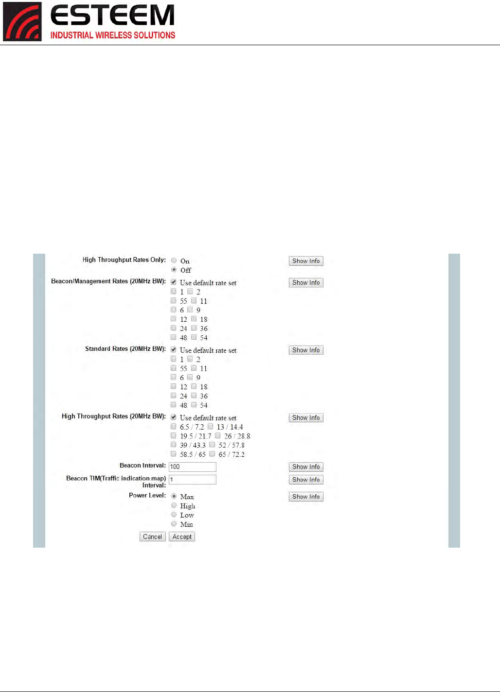
APPENDIXC
RADIOCONFIGURATION
Revised: 27 Jan 2017 APX C-2 ESTeem Horizon Series
RFDataRateConfiguration
TheRFdatarateoftheHorizoncanbeprogrammedforoperationatmultipledatarates.TheRFdataratecanbesetforafixed
rateoraspecificrangethatisdynamicallyscaledbytheHorizonfrommonitoringthereceivedsignalquality.Dynamicscaling
meansthattheHorizonwilloperateatthehighestRFdataratethatisprogrammedintounit.Ifthereceiveddataqualitydrops
belowtherequiredminimumsforreliablecommunications,theHorizonwillreducethedataratetothenextloweststepto
increasesignalquality.ConverselyifthesignalqualityincreasesabovetheminimumstheHorizonwillincreasetheRFdatarate
thenexthighestlevel.
TheESTeemHorizonissetatthefactorytooperateatmaximizedscalingspeeddataratesandshouldnotneedadjustment.The
RFDataRateisprogrammedintheHorizonthroughtheAdvancedMenu>WirelessLANSettings>wlan0deviceandthevaluefor
CommunicationRatesand802.11nCommunicationRateIndex:.IntheexampleshowninFigure2theRFDateRateis
programmedtodynamicscalealldatarates(recommendfactorydefaultsetting).Tosetthevaluesforthedatarate,checkthe
boxnexttothelisteddataratetoenablethisrateforoperation.
Figure2:AdvancedDataRateSelection
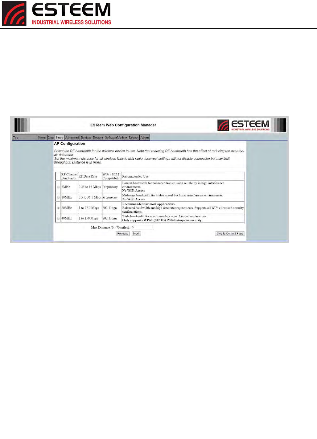
APPENDIXC
RADIOCONFIGURATION
Revised: 27 Jan 2017 APX C-3 ESTeem Horizon Series
RFBandwidths
TheHorizonradioshaveadjustableRFbandwidthsforoperation.ReducingtheRFbandwidthincreasesthenumberofavailable
channelsandtheradio'sabilitytorejectRFinterference.DifferentmodelsoftheHorizonserieswillhavedifferentavailable
bandwidthsdependinguponthefrequencyofoperation.Forexample,Figure3showstheconfigurationoftheHorizon2.4
GHz’savailablebandwidths.
NOTE:AllESTeemradiosinthesamenetworkMUSTbeonthesamefrequencychannelandusethesamebandwidth
selection.
Figure3:Horizon2.4GHzBandwidthSelection

APPENDIXC
RADIOCONFIGURATION
Revised: 27 Jan 2017 APX C-4 ESTeem Horizon Series
DataRatesandThroughput
TheHorizonseriesradiosaredesignedtodynamicallychangetheirdataratebasedupontheircurrentreceivesignalstrength
andbackgroundnoisetoachievethehighestthroughput.ItishighlyrecommendedtoallowtheHorizontodynamicallyscaleto
thebestdatarategiventheoperationconditions.ThefollowingtablesshowthedataratestheHorizonradioswilluseandthe
receivesignalstrengthrequiredforeachlevel.
Glossary
LegacyIndex–ThisindexshowsthedataratestheHorizonradioswillusewhenoperatingatlegacy802.11(802.11g,802.11bor
802.11a)ratesandtocommunicatewiththeolderESTeemModel195Eseriesradiomodems.
HTMCSIndex–HighThroughput(HT)ModulationandCodingScheme(MCS)indexvaluelistgiveseverycombinationof
"numberofspatialstreams+modulationtype+codingrate"thatispossible.InpracticetheachievableMCSvaluewilldepend
onalargenumberofvariablessuchasreceivesignalstrength,availablebandwidth,RFbackgroundnoiseandotherusersona
givenchannel.TheMCSvaluewillonlytellthe'overtheair'datarateofalinkandnotdefinewhattheactualusablethroughput
(seebelow).
DSSS–DirectSequenceSpreadSpectrum.Thisisalegacymodulationtypeusedin802.11bwirelessnetworks.
OFDM–OrthogonalFrequency‐DivisionMultiplexingisthelatestmodulationschemeusedasadigitalmulti‐carriermodulation
method.Alargenumberofcloselyspacedorthogonalsub‐carriersignalsareusedtocarrydataonseveralparalleldatastreams
orchannelstoachievethehigherthroughputsofthe802.11nprotocols.
Modul.(Modulation)‐Themodulationishowthedataistransportedonthecarrierfrequency.Therearemultipletypesof
modulationusedintheHorizonhardwareandtheyarelistedonthefollowingchartsstrictlyforreference.
CodingRate‐Thisisanindicationofhowmuchofthedatastreamisactuallybeingusedtotransmitusabledata.Thisis
expressedasafractionwiththemostefficientratebeing5/6or83.3%ofthedatastreambeingused.
GuardInterval–TheGuardInterval(GI)iseffectivelyaveryshortpausebetweenpackettransmissiontoallowforanyfalse
informationtobeignored.ThelongerGuardIntervalcanimprovereliabilityinmoresaturatedwirelessnetworks.Theinterval
shownisinnanoseconds(ns)oronebillionthofasecond(x10‐9).
Bandwidth‐Alsoknownaschannelwidth,thisishowmuchofthefrequencyspectrumisbeingusedtotransportdata.The
maximumbandwidthusedbytheHorizonseriesis40MHz.Thetableshowsvaluesforavailablebandwidthbymodelwhich
directlycorrelatetotheradiothroughput.Forexample,a10MHzchannelwillprovidehalftheDataRateofa20MHz.
Signal–Thisistheamountofreceivesignalstrengthrequiredtoachieveagivendatarate.Manyfactorssuchasradio
backgroundnoiseandotherusersinafrequencychannelwillgreatlyaffecttheamountofsignalstrengthrequired.Thevalues
providedaretobeusedasareferenceforlineofsight(LOS)path‐losscalculations.
RFRate–Thisistherateatwhichoneradiotransmitsdatafromonetoanother.
Throughput–Thedisplayedthroughputisanapproximationoftheeffectivedatarateofaradiosystemcomparedtosending
Ethernetdataoverstandardwire.ThisnumbertakesintoaccountfactorslikeRFpacketoverhead,retries,andlatencyofthe
radio.
dBm–Decibelsinreferencetoamilliwatt(mW).Thisisastandardunitofreceivesignalstrength.
Mbps–Mega(million)bitspersecond.Thestandardunitofdatarateusedinhighspeedwirelessdevices.
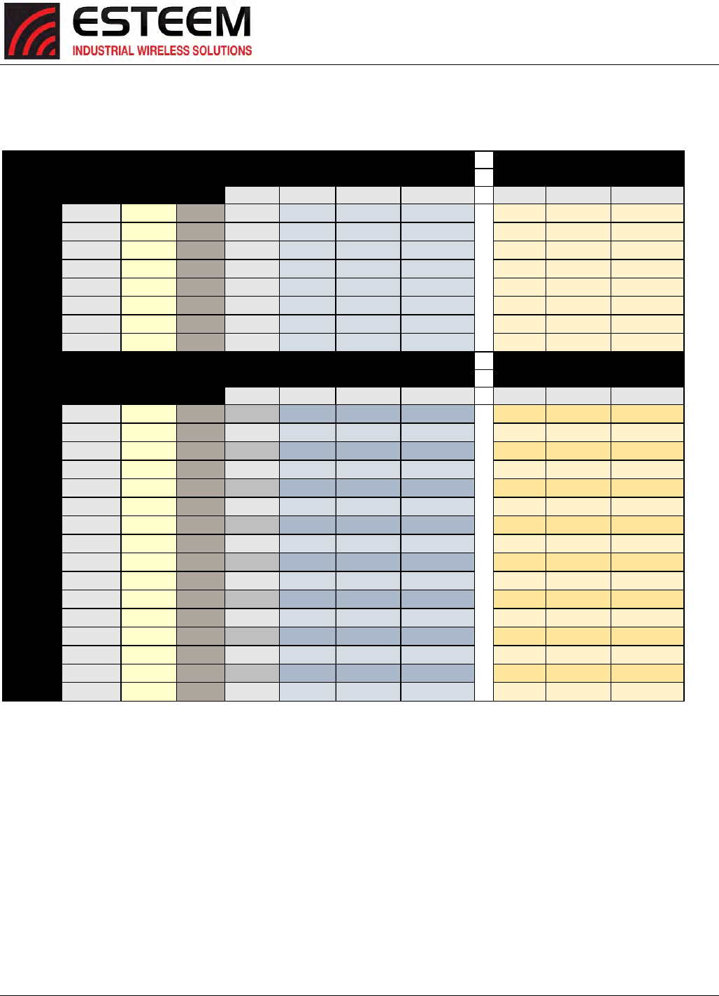
APPENDIXC
RADIOCONFIGURATION
Revised: 27 Jan 2017 APX C-5 ESTeem Horizon Series
Horizon900MHzDataRateChart#1
Legacy DSSS or Modul. Coding
Index OFDM Signal RF Rate Throughput Signal RF Rate Throughput
dBm Mbps Mbps dBm Mbps Mbps
6OFDM BPSK 1/2
-93 6.00 1.88 -96 3.00 0.94
9OFDM BPSK 3/4
-91 9.00 4.22 -94 4.50 2.11
12 OFDM QPSK 1/2
-91 12.00 3.75 -94 6.00 1.88
18 OFDM QPSK 3/4
-88 18.00 8.44 -91 9.00 4.22
24 OFDM 16-QAM 1/2
-87 24.00 7.50 -90 12.00 3.75
36 OFDM 16-QAM 3/4
-82 36.00 16.88 -85 18.00 8.44
48 OFDM 64-QAM 2/3
-78 48.00 20.00 -81 24.00 10.00
54 OFDM 64-QAM 3/4
-73 54.00 25.31 -76 27.00 12.66
HT MCS Spatial Modul. Coding Guard
Index Streams Interval Signal RF Rate Throughput Signal RF Rate Throughput
dBm Mbps Mbps dBm Mbps Mbps
01 BPSK 1/2 800ns
-94 6.50 2.23 -97 3.25 1.12
01 BPSK 1/2 400ns
-94 7.20 2.48 -97 3.60 1.24
1
1
QPSK 1/2 800ns
-85 13.00 4.47 -88 6.50 2.23
1
1
QPSK 1/2 400ns
-85 14.40 4.95 -88 7.20 2.48
21QPSK 3/4 800ns
-82 19.50 10.05 -85 9.75 5.03
21QPSK 3/4 400ns
-82 21.70 11.19 -85 10.85 5.59
31 16-QAM 1/2 800ns
-80 26.00 8.94 -83 13.00 4.47
31 16-QAM 1/2 400ns
-80 28.90 9.93 -83 14.45 4.97
41 16-QAM 3/4 800ns
-80 39.00 20.11 -83 19.50 10.05
41 16-QAM 3/4 400ns
-80 43.30 22.33 -83 21.65 11.16
51 64-QAM 2/3 800ns
-78 52.00 23.83 -81 26.00 11.92
51 64-QAM 2/3 400ns
-78 57.80 26.49 -81 28.90 13.25
61 64-QAM 3/4 800ns
-73 58.50 30.16 -76 29.25 15.08
61 64-QAM 3/4 400ns
-73 65.00 33.52 -76 32.50 16.76
71 64-QAM 5/6 800ns
-68 65.00 37.24 -71 32.50 18.62
71 64-QAM 5/6 400ns
-68 72.20 41.36 -71 36.10 20.68
20 MHz Bandwidth 10 MHz Bandwidth
20 MHz Bandwidth 10 MHz Bandwidth
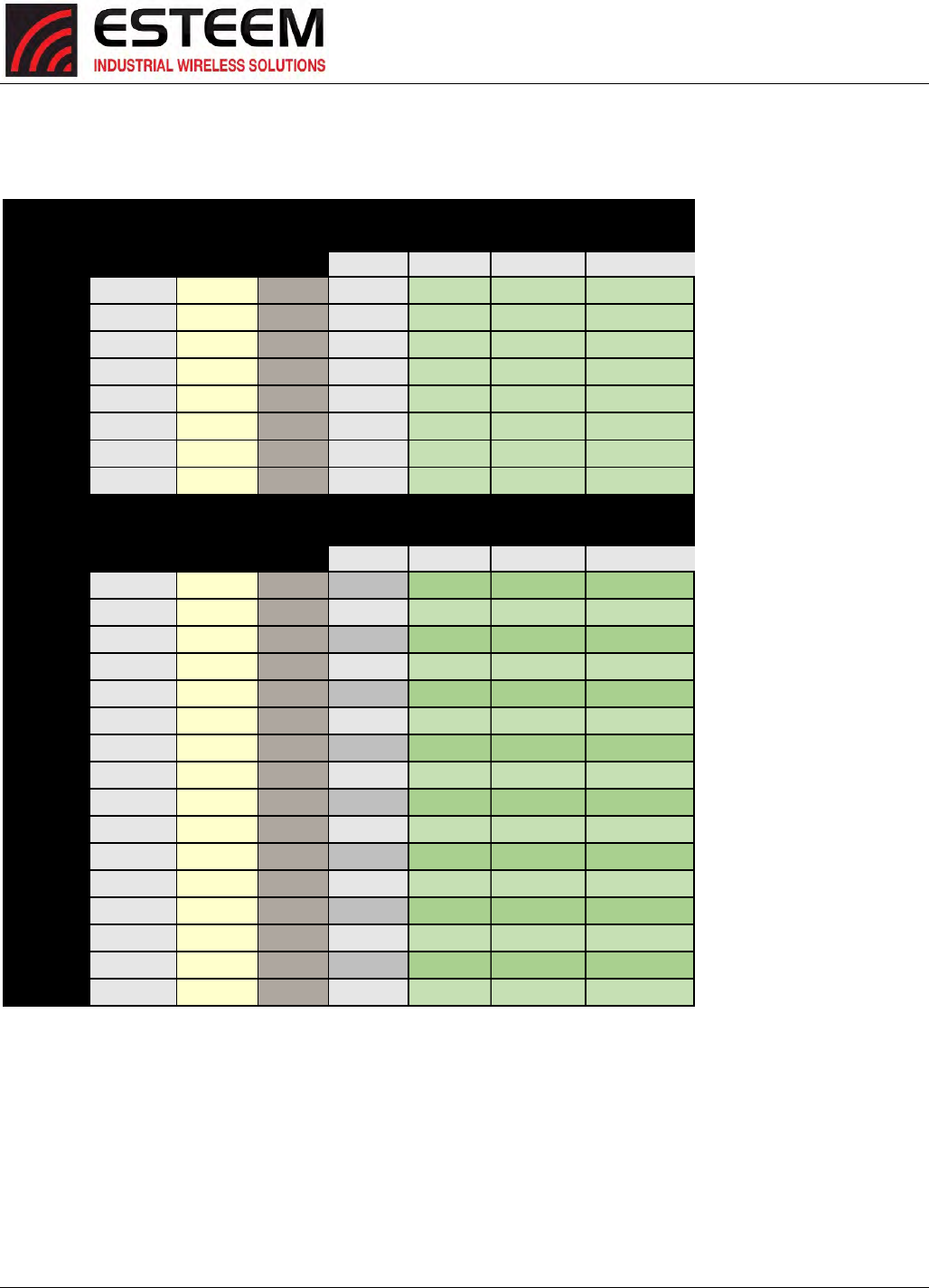
APPENDIXC
RADIOCONFIGURATION
Revised: 27 Jan 2017 APX C-6 ESTeem Horizon Series
Horizon900MHzDataRateChart#2
Legacy DSSS or Modul. Coding
Index OFDM Signal RF Rate Throughput
dBm Mbps Mbps
6OFDM BPSK 1/2
-99 1.50 0.47
9OFDM BPSK 3/4
-97 2.25 1.05
12 OFDM QPSK 1/2
-97 3.00 0.94
18 OFDM QPSK 3/4
-94 4.50 2.11
24 OFDM 16-QAM 1/2
-93 6.00 1.88
36 OFDM 16-QAM 3/4
-88 9.00 4.22
48 OFDM 64-QAM 2/3
-84 12.00 5.00
54 OFDM 64-QAM 3/4
-79 13.50 6.33
HT MCS Spatial Modul. Coding Guard
Index Streams Interval Signal RF Rate Throughput
dBm Mbps Mbps
01BPSK 1/2 800ns
-100 1.63 0.56
01BPSK 1/2 400ns
-100 1.80 0.62
1
1
QPSK 1/2 800ns
-91 3.25 1.12
1
1
QPSK 1/2 400ns
-91 3.60 1.24
21 QPSK 3/4 800ns
-88 4.88 2.51
21 QPSK 3/4 400ns
-88 5.43 2.80
31 16-QAM 1/2 800ns
-86 6.50 2.23
31 16-QAM 1/2 400ns
-86 7.23 2.48
41 16-QAM 3/4 800ns
-86 9.75 5.03
41 16-QAM 3/4 400ns
-86 10.83 5.58
51 64-QAM 2/3 800ns
-84 13.00 5.96
51 64-QAM 2/3 400ns
-84 14.45 6.62
61 64-QAM 3/4 800ns
-79 14.63 7.54
61 64-QAM 3/4 400ns
-79 16.25 8.38
71 64-QAM 5/6 800ns
-74 16.25 9.31
71 64-QAM 5/6 400ns
-74 18.05 10.34
5 MHz Bandwidth
5 MHz Bandwidth
APPENDIXC
RADIOCONFIGURATION
Revised: 27 Jan 2017 APX C-7 ESTeem Horizon Series
Horizon2.4GHzDataRateChart#1
Legacy DSSS or Modul. Coding
Index OFDM Signal RF Rate Throughput
dBm Mbps Mbps
1DSSS BPSK 1/11
-97 1.00 0.06
2DSSS QPSK 1/11
-95 2.00 0.11
5.5 DSSS CCK 4/8
-93 5.50 1.72
11 DSSS CCK 4/8
-91 11.00 3.44
6OFDM BPSK 1/2
-93 6.00 1.88
9OFDM BPSK 3/4
-91 9.00 4.22
12 OFDM QPSK 1/2
-91 12.00 3.75
18 OFDM QPSK 3/4
-88 18.00 8.44
24 OFDM 16-QAM 1/2
-87 24.00 7.50
36 OFDM 16-QAM 3/4
-82 36.00 16.88
48 OFDM 64-QAM 2/3
-78 48.00 20.00
54 OFDM 64-QAM 3/4
-73 54.00 25.31
HT MCS Spatial Modul. Coding Guard
Index Streams Interval Signal RF Rate Throughput Signal RF Rate Throughput
dBm Mbps Mbps dBm Mbps Mbps
01BPSK 1/2 800ns
-94 6.50 2.23 -91 13.50 4.64
01BPSK 1/2 400ns
-94 7.20 2.48 -91 15.00 5.16
1
1
QPSK 1/2 800ns
-85 13.00 4.47 -82 27.00 9.28
1
1
QPSK 1/2 400ns
-85 14.40 4.95 -82 30.00 10.31
21QPSK 3/4 800ns
-82 19.50 10.05 -79 40.50 20.88
21QPSK 3/4 400ns
-82 21.70 11.19 -79 45.00 23.20
3116-QAM
1/2 800ns
-80 26.00 8.94 -77 54.00 18.56
3116-QAM
1/2 400ns
-80 28.90 9.93 -77 60.00 20.63
4116-QAM
3/4 800ns
-80 39.00 20.11 -77 81.00 41.77
4116-QAM
3/4 400ns
-80 43.30 22.33 -77 90.00 46.41
5164-QAM
2/3 800ns
-78 52.00 23.83 -75 108.00 49.50
5164-QAM
2/3 400ns
-78 57.80 26.49 -75 120.00 55.00
6164-QAM
3/4 800ns
-73 58.50 30.16 -70 121.50 62.65
6164-QAM
3/4 400ns
-73 65.00 33.52 -70 135.00 69.61
7164-QAM
5/6 800ns
-68 65.00 37.24 -65 135.00 77.34
7164-QAM
5/6 400ns
-68 72.20 41.36 -65 150.00 85.94
Legacy Rates Not Supported
at 40 MHz Bandwidth
40 MHz Bandwidth20 MHz Bandwidth
40 MHz Bandwidth20 MHz Bandwidth
APPENDIXC
RADIOCONFIGURATION
Revised: 27 Jan 2017 APX C-8 ESTeem Horizon Series
Horizon2.4GHzDataRateChart#2
Legacy DSSS or Modul. Coding
Index OFDM Signal RF Rate Throughput Signal RF Rate Throughput
dBm Mbps Mbps dBm Mbps Mbps
1DSSS BPSK 1/11
-103 0.25 0.01 -100 0.50 0.03
2DSSS QPSK 1/11
-101 0.50 0.03 -98 1.00 0.06
5.5 DSSS CCK 4/8
-99 1.38 0.43 -96 2.75 0.86
11 DSSS CCK 4/8
-97 2.75 0.86 -94 5.50 1.72
6OFDM BPSK 1/2
-99 1.50 0.47 -96 3.00 0.94
9OFDM BPSK 3/4
-97 2.25 1.05 -94 4.50 2.11
12 OFDM QPSK 1/2
-97 3.00 0.94 -94 6.00 1.88
18 OFDM QPSK 3/4
-94 4.50 2.11 -91 9.00 4.22
24 OFDM 16-QAM 1/2
-93 6.00 1.88 -90 12.00 3.75
36 OFDM 16-QAM 3/4
-88 9.00 4.22 -85 18.00 8.44
48 OFDM 64-QAM 2/3
-84 12.00 5.00 -81 24.00 10.00
54 OFDM 64-QAM 3/4
-79 13.50 6.33 -76 27.00 12.66
HT MCS Spatial Modul. Coding Guard
Index Streams Interval Signal RF Rate Throughput Signal RF Rate Throughput
dBm Mbps Mbps dBm Mbps Mbps
01BPSK 1/2 800ns
-100 1.63 0.56 -97 3.25 1.12
01BPSK 1/2 400ns
-100 1.80 0.62 -97 3.60 1.24
1
1
QPSK 1/2 800ns
-91 3.25 1.12 -88 6.50 2.23
1
1
QPSK 1/2 400ns
-91 3.60 1.24 -88 7.20 2.48
21QPSK 3/4 800ns
-88 4.88 2.51 -85 9.75 5.03
21QPSK 3/4 400ns
-88 5.43 2.80 -85 10.85 5.59
3116-QAM
1/2 800ns
-86 6.50 2.23 -83 13.00 4.47
3116-QAM
1/2 400ns
-86 7.23 2.48 -83 14.45 4.97
4116-QAM
3/4 800ns
-86 9.75 5.03 -83 19.50 10.05
4116-QAM
3/4 400ns
-86 10.83 5.58 -83 21.65 11.16
5164-QAM
2/3 800ns
-84 13.00 5.96 -81 26.00 11.92
5164-QAM
2/3 400ns
-84 14.45 6.62 -81 28.90 13.25
6164-QAM
3/4 800ns
-79 14.63 7.54 -76 29.25 15.08
6164-QAM
3/4 400ns
-79 16.25 8.38 -76 32.50 16.76
7164-QAM
5/6 800ns
-74 16.25 9.31 -71 32.50 18.62
7164-QAM
5/6 400ns
-74 18.05 10.34 -71 36.10 20.68
5 MHz Bandwidth
5 MHz Bandwidth
10 MHz Bandwidth
10 MHz Bandwidth
APPENDIXC
RADIOCONFIGURATION
Revised: 27 Jan 2017 APX C-9 ESTeem Horizon Series
Horizon4.9GHzDataRateChart
Legacy DSSS or Modul. Coding
Index OFDM Signal RF Rate Throughput
dBm Mbps Mbps
1DSSS BPSK 1/11
-97 1.00 0.06
2DSSS QPSK 1/11
-95 2.00 0.11
5.5 DSSS CCK 4/8
-93 5.50 1.72
11 DSSS CCK 4/8
-91 11.00 3.44
6OFDM BPSK 1/2
-93 6.00 1.88
9OFDM BPSK 3/4
-91 9.00 4.22
12 OFDM QPSK 1/2
-91 12.00 3.75
18 OFDM QPSK 3/4
-88 18.00 8.44
24 OFDM 16-QAM 1/2
-87 24.00 7.50
36 OFDM 16-QAM 3/4
-82 36.00 16.88
48 OFDM 64-QAM 2/3
-78 48.00 20.00
54 OFDM 64-QAM 3/4
-73 54.00 25.31
HT MCS Spatial Modul. Coding Guard
Index Streams Interval Signal RF Rate Throughput
dBm Mbps Mbps
01BPSK 1/2 800ns
-94 6.50 2.23
01BPSK 1/2 400ns
-94 7.20 2.48
1
1
QPSK 1/2 800ns
-85 13.00 4.47
1
1
QPSK 1/2 400ns
-85 14.40 4.95
21QPSK 3/4 800ns
-82 19.50 10.05
21QPSK 3/4 400ns
-82 21.70 11.19
3116-QAM
1/2 800ns
-80 26.00 8.94
3116-QAM
1/2 400ns
-80 28.90 9.93
4116-QAM
3/4 800ns
-80 39.00 20.11
4116-QAM
3/4 400ns
-80 43.30 22.33
5164-QAM
2/3 800ns
-78 52.00 23.83
5164-QAM
2/3 400ns
-78 57.80 26.49
6164-QAM
3/4 800ns
-73 58.50 30.16
6164-QAM
3/4 400ns
-73 65.00 33.52
7164-QAM
5/6 800ns
-68 65.00 37.24
7164-QAM
5/6 400ns
-68 72.20 41.36
20 MHz Bandwidth
20 MHz Bandwidth
APPENDIXC
RADIOCONFIGURATION
Revised: 27 Jan 2017 APX C-10 ESTeem Horizon Series
Horizon5.8GHzDataRateChart#1
Legacy DSSS or Modul. Coding
Index OFDM Signal RF Rate Throughput
dBm Mbps Mbps
6OFDM BPSK 1/2
-93 6.00 1.88
9OFDM BPSK 3/4
-91 9.00 4.22
12 OFDM QPSK 1/2
-91 12.00 3.75
18 OFDM QPSK 3/4
-88 18.00 8.44
24 OFDM 16-QAM 1/2
-87 24.00 7.50
36 OFDM 16-QAM 3/4
-82 36.00 16.88
48 OFDM 64-QAM 2/3
-78 48.00 20.00
54 OFDM 64-QAM 3/4
-73 54.00 25.31
HT MCS Spatial Modul. Coding Guard
Index Streams Interval Signal RF Rate Throughput Signal RF Rate Throughput
dBm Mbps Mbps dBm Mbps Mbps
01BPSK 1/2 800ns
-94 6.50 2.23 -91 13.50 4.64
01BPSK 1/2 400ns
-94 7.20 2.48 -91 15.00 5.16
1
1
QPSK 1/2 800ns
-85 13.00 4.47 -82 27.00 9.28
1
1
QPSK 1/2 400ns
-85 14.40 4.95 -82 30.00 10.31
21QPSK 3/4 800ns
-82 19.50 10.05 -79 40.50 20.88
21QPSK 3/4 400ns
-82 21.70 11.19 -79 45.00 23.20
31 16-QAM 1/2 800ns
-80 26.00 8.94 -77 54.00 18.56
31 16-QAM 1/2 400ns
-80 28.90 9.93 -77 60.00 20.63
41 16-QAM 3/4 800ns
-80 39.00 20.11 -77 81.00 41.77
41 16-QAM 3/4 400ns
-80 43.30 22.33 -77 90.00 46.41
51 64-QAM 2/3 800ns
-78 52.00 23.83 -75 108.00 49.50
51 64-QAM 2/3 400ns
-78 57.80 26.49 -75 120.00 55.00
61 64-QAM 3/4 800ns
-73 58.50 30.16 -70 121.50 62.65
61 64-QAM 3/4 400ns
-73 65.00 33.52 -70 135.00 69.61
71 64-QAM 5/6 800ns
-68 65.00 37.24 -65 135.00 77.34
71 64-QAM 5/6 400ns
-68 72.20 41.36 -65 150.00 85.94
82BPSK 1/2 800ns
-94 13.00 4.47 -91 27.00 9.28
82BPSK 1/2 400ns
-94 14.40 4.95 -91 30.00 10.31
92QPSK 1/2 800ns
-85 26.00 8.94 -82 54.00 18.56
92QPSK 1/2 400ns
-85 28.80 9.90 -82 60.00 20.63
10 2QPSK 3/4 800ns
-82 39.00 20.11 -79 81.00 41.77
10 2QPSK 3/4 400ns
-82 43.40 22.38 -79 90.00 46.41
11 2 16-QAM 1/2 800ns
-80 52.00 17.88 -77 108.00 37.13
11 2 16-QAM 1/2 400ns
-80 57.80 19.87 -77 120.00 41.25
12 2 16-QAM 3/4 800ns
-80 78.00 40.22 -77 162.00 83.53
12 2 16-QAM 3/4 400ns
-80 86.60 44.65 -77 180.00 92.81
13 2 64-QAM 2/3 800ns
-78 104.00 47.67 -75 216.00 99.00
13 2 64-QAM 2/3 400ns
-78 115.60 52.98 -75 240.00 110.00
14 2 64-QAM 3/4 800ns
-73 117.00 60.33 -70 243.00 125.30
14 2 64-QAM 3/4 400ns
-73 130.00 67.03 -70 270.00 139.22
15 2 64-QAM 5/6 800ns
-68 130.00 74.48 -65 270.00 154.69
15 2 64-QAM 5/6 400ns
-68 144.40 82.73 -65 300.00 171.88
20 MHz Bandwidth 40 MHz Bandwidth
Le
g
ac
y
Rates Not Supported
at 40 MHz Bandwidth
20 MHz Bandwidth 40 MHz Bandwidth
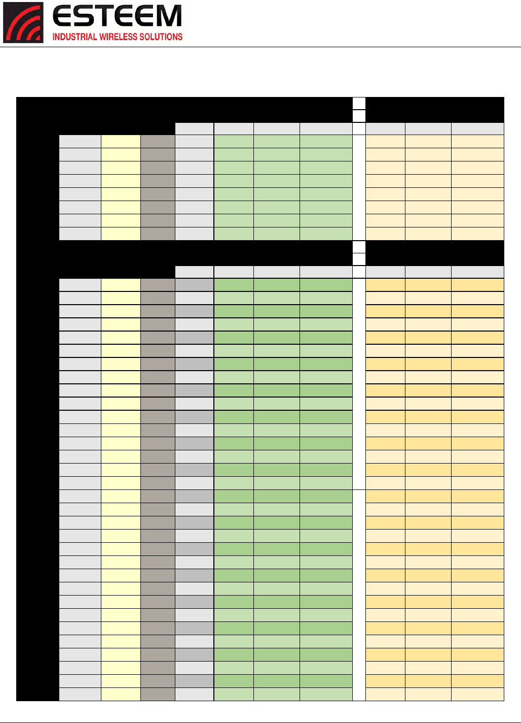
APPENDIXC
RADIOCONFIGURATION
Revised: 27 Jan 2017 APX C-11 ESTeem Horizon Series
Horizon5.8GHzDataRateChart#2
Legacy DSSS or Modul. Coding
Index OFDM Signal RF Rate Throughput Signal RF Rate Throughput
dBm Mbps Mbps dBm Mbps Mbps
6OFDM BPSK 1/2 -99 1.50 0.47 -96 3.00 0.94
9OFDM BPSK 3/4 -97 2.25 1.05 -94 4.50 2.11
12 OFDM QPSK 1/2 -97 3.00 0.94 -94 6.00 1.88
18 OFDM QPSK 3/4 -94 4.50 2.11 -91 9.00 4.22
24 OFDM 16-QAM 1/2 -93 6.00 1.88 -90 12.00 3.75
36 OFDM 16-QAM 3/4 -88 9.00 4.22 -85 18.00 8.44
48 OFDM 64-QAM 2/3 -84 12.00 5.00 -81 24.00 10.00
54 OFDM 64-QAM 3/4 -79 13.50 6.33 -76 27.00 12.66
HT MCS Spatial Modul. Coding Guard
Index Streams Interval Signal RF Rate Throughput Signal RF Rate Throughput
dBm Mbps Mbps dBm Mbps Mbps
01BPSK 1/2 800ns -100 1.63 0.56 -97 3.25 1.12
01BPSK 1/2 400ns -100 1.80 0.62 -97 3.60 1.24
11QPSK 1/2 800ns -91 3.25 1.12 -88 6.50 2.23
11QPSK 1/2 400ns -91 3.60 1.24 -88 7.20 2.48
21QPSK 3/4 800ns -88 4.88 2.51 -85 9.75 5.03
21QPSK 3/4 400ns -88 5.43 2.80 -85 10.85 5.59
3116-QAM
1/2 800ns -86 6.50 2.23 -83 13.00 4.47
3116-QAM
1/2 400ns -86 7.23 2.48 -83 14.45 4.97
4116-QAM
3/4 800ns -86 9.75 5.03 -83 19.50 10.05
4116-QAM
3/4 400ns -86 10.83 5.58 -83 21.65 11.16
5164-QAM
2/3 800ns -84 13.00 5.96 -81 26.00 11.92
5164-QAM
2/3 400ns -84 14.45 6.62 -81 28.90 13.25
6164-QAM
3/4 800ns -79 14.63 7.54 -76 29.25 15.08
6164-QAM
3/4 400ns -79 16.25 8.38 -76 32.50 16.76
7164-QAM
5/6 800ns -74 16.25 9.31 -71 32.50 18.62
7164-QAM
5/6 400ns -74 18.05 10.34 -71 36.10 20.68
82BPSK 1/2 800ns -100 3.25 1.12 -97 6.50 2.23
82BPSK 1/2 400ns -100 3.60 1.24 -97 7.20 2.48
92QPSK 1/2 800ns -91 6.50 2.23 -88 13.00 4.47
92QPSK 1/2 400ns -91 7.20 2.48 -88 14.40 4.95
10 2QPSK 3/4 800ns -88 9.75 5.03 -85 19.50 10.05
10 2QPSK 3/4 400ns -88 10.85 5.59 -85 21.70 11.19
11 216-QAM
1/2 800ns -86 13.00 4.47 -83 26.00 8.94
11 216-QAM
1/2 400ns -86 14.45 4.97 -83 28.90 9.93
12 216-QAM
3/4 800ns -86 19.50 10.05 -83 39.00 20.11
12 216-QAM
3/4 400ns -86 21.65 11.16 -83 43.30 22.33
13 264-QAM
2/3 800ns -84 26.00 11.92 -81 52.00 23.83
13 264-QAM
2/3 400ns -84 28.90 13.25 -81 57.80 26.49
14 264-QAM
3/4 800ns -79 29.25 15.08 -76 58.50 30.16
14 264-QAM
3/4 400ns -79 32.50 16.76 -76 65.00 33.52
15 264-QAM
5/6 800ns -74 32.50 18.62 -71 65.00 37.24
15 264-QAM
5/6 400ns -74 36.10 20.68 -71 72.20 41.36
5 MHz Bandwidth 10 MHz Bandwidth
5 MHz Bandwidth 10 MHz Bandwidth
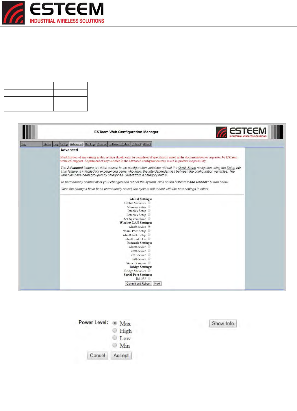
APPENDIXC
RADIOCONFIGURATION
Revised: 27 Jan 2017 APX C-12 ESTeem Horizon Series
SETTINGRFPOWERLEVEL
TheESTeemHorizonpeakpowerisadjustableinoutputpowerfromtheadvancedconfigurationmenu.Theoutputpoweris
adjustedontheAdvancedMenu>WirelessLANSettings>wlan0devicescreen(Figure4)oftheWebConfigurationManager.
SelectthevalueandpresstheSaveSettingsbutton.
Max(Maximum)FullPower
Hi(High)75%Power
Lo(Low)50%Power
Min(Minimum)25%Power
Figure5:PowerLevelSettings
Figure4:AdvancedGlobalVariables

APPENDIXD
SECURITY
Revised: 27 Jun 16 APX D-1 ESTeem Horizon Series
OVERVIEW
ThesecurityfortheESTeemHorizon,likeallnetworksecurity,mustbemulti‐layered.Onelevelofsecurityisneverenoughto
makesurethatdatadoesnotendupinthewronghands.Pleasereviewthefollowingsecuritylevelsanddecidewhatisthemost
appropriateforyournetwork.
AES‐CCMP(802.11iandWPA‐2)
AES‐CCMP(AdvancedEncryptionStandard‐CounterModeCBC‐MACProtocol)istheencryptionalgorithmusedintheIEEE802.11i
andWPA‐2securityprotocols.Thisnationalencryptionstandardusesa128bit‐AESblockcipherandCCMPtechniquetoensure
thehighestlevelofsecurityandintegrityavailableonawirelessnetwork.AES‐CCMPincorporatestwosophisticatedcryptographic
techniques(countermodeandCBC‐MAC)andadaptsthemtoEthernetframestoprovidearobustsecurityprotocolbetweenthe
mobileclientandtheaccesspoint.AESitselfisaverystrongcipher,butcountermodemakesitdifficultforaneavesdroppertospot
patterns,andtheCBC‐MACmessageintegritymethodensuresthatmessageshavenotbeentamperedwith.TheESTeemHorizon
iscompatibleaseitheranAccessPointorclientineitherWPA2orIEEE802.11isecuritysystems.
Wi‐FiProtectedAccess2withPresharedKey(WPA2PSK)
WPA2PSKusesacommonpassphrase(presharedkey)betweentheAccessPoint(AP)andtheclienttobeginasecure
communicationsession.ThispassphrasemustbeenteredexactlythesameinboththeAccessPointandtheclient.Thispassphrase
isusedtoauthenticatecommunicationsessionbetweentheAPandclienttobeginthesecurewirelessnetworkingsession.
Wi‐FiProtectedAccess2withEnterpriseServer(WPAEnterprise)
LikeWPA2PSK,WPA2EnterpriseverifiestheauthenticityoftheAccessPointandclient,butusesan802.1xbackendauthentication
serverhandlingtheauthenticationdecision.ThemostcommonlytypeofauthenticationserverisaRADIUSserver.TheESTeem
HorizoncanbeconfiguredtooperatewithanestablishedRADIUSserveronthenetwork.
WPA
Wi‐FiProtectedAccesswithPresharedKey(WPAPSK)
WPA,whichuses802.1x,wasintroducedin2003toimproveontheauthenticationandencryptionfeaturesofWEP.All
authenticationishandledwithinthisaccesspointdevice.WPAhastwosignificantadvantagesoverWEP:
1. Anencryptionkeydifferingineverypacket.TheTKIP(TemporalKeyIntegrityProtocol)mechanismsharesastartingkey
betweendevices.Eachdevicethenchangestheirencryptionkeyforeverypacket.Itisextremelydifficultforhackerstoread
messageseveniftheyhaveinterceptedthedata.
2. CertificateAuthentication(CA)canbeused,blockingahackerposingasavaliduser.
Wi‐FiProtectedAccesswithEnterpriseServer(WPAEnterprise)
LikeWPAPSK,WPAEnterpriseverifiestheauthenticityoftheAccessPointandclient,butusesan802.1xbackendauthentication
serverhandlingtheauthenticationdecision.ThemostcommonlytypeofauthenticationserverisaRADIUSserver.TheESTeem
HorizoncanbeconfiguredtooperatewithanestablishedRADIUSserveronthenetwork.
WPAisserver/clientrelationshipfromasoftwaredriveronacomputer’swirelessLAN(WLAN)cardtoanAccessPoint.Thescope
ofWPAislimitedinusetothisconfigurationonly.TheESTeemHorizoncansupportWPAEnterpriseandPSKasanAccessPoint,
butthelevelofsecurityontheBridginglayerisconfiguredseparately.

APPENDIXD
SECURITY
Revised: 27 Jun 16 APX D-2 ESTeem Horizon Series
128‐BITWEP
The128WEPusesaparticularalgorithmcalledRC4encryptiontoencodeanddecodetrafficthatisbasedona104‐bitencryption
keyanda24‐bitInitializationVector(IV).RC4startswitharelativelyshortencryptionkey(104bits)thatisexpandedintoanearly
infinitestreamofkeystoaccompanythestreamofpackets.
ThebasicconceptofRC4isgood,butthewayit’simplementedinWEPleavesitopentocompromise.Theresearchersthattest
theintegrityofthesystemusuallyfocusononepieceoftheimplementation,theInitializationVector(IV).
TheIV(24bits)isthealgorithmcomponentthat’ssupposedtokeepexpandedkeysfromrepeating.Fromtheresearcher’spoint
ofview,ahigh‐volumeaccesspointismathematicallyguaranteedtoreusethesamekeystreamatleastonceaday.Whenthis
happens,it’scalledanIVcollisionthisbecomesasoftspottoenterthesystem.
Theresearchersaren’tsayingthatit’seasytobreakintothesystem,orthatit’sbeingdoneonaregularbasis,onlythatitispossible
andadministratorsshouldconsiderwaystoreducethepossibility
AccessControlList(ACL)
TheACLisoneofthesimplestyetmostsecuremethodsofnetworksecurity.TheACLisaconfigurableMACfilterintheModel
192EthatcanbesettoallowspecificMACaddressonthewirelessnetworkbyindividualaddressoraddressranges.Thesame
filtercanalsobesettorejectindividualMACaddressesoraddressranges.
TheMACaddressisaunique,6hexadecimalfieldaddressassignedatthemanufacturerthatcannotbechanged.TheMACaddress
istraceablethroughtheIEEEgoverningbodytothemanufacturerandisthe“fingerprint”forallEthernetdevices.
UsingacombinationofboththeWPAor128‐BitWEPencryptionandtheACLfilterprovidetheESTeemanextremelysecure
wirelessnetworkinglayer.
DisablingBroadcastProbesandHidingSSID
Asimplebutveryeffectivewayofsecuringanetworkistomakethenetworkdifficulttofind.Bydisablingbroadcastprobesand
hidingtheServiceSetIdentification(SSID),wirelessandnetwork“sniffers”willnotbeabletofindyourESTeemHorizonnetwork.
Togainaccesstothewirelessnetwork,youwouldberequiredtohavetheSSIDandallsecurityloadedintheWLANcardsoftware
priortoenteringthenetwork.
ProprietaryBridgeCommunication
AlthoughtheESTeemHorizoniscompatiblewiththeopencommunicationstandardsIEEE802.11gand802.11b,therepeater
communicationbetweentheunitsisaproprietarycommunicationlink.Noothermanufacturerofwirelesshardwarecanaccess
theESTeemrepeaternetworkwhenbridgingbetweenEthernetnetworks.Thisproprietarycommunicationlayer,incombination
withtheothersecuritysettings,allowsyouastheusertorejectwirelessclientsintothenetworkifsodesired.Whenusedin
conjunctionwiththeAccessControlListthe802.11gand802.11bclientaccesscanberemoved.
Thesecuritylevelofthebridgecommunicationlinkisconfigurablefor64‐BitWEP,128‐BitWEPorTKIPandiscompletely
independentoftheclientaccessleveloranyothercommunicationlinklevel.Forexample,anESTeemHorizoncanbeconfigured
forWPAEnterpriseforclientlevelaccess,communicatetoanotherESTeemHorizonusingaTKIPbridgelinkandalsocommunicate
128‐BitWEPtoourolderESTeemModel192Eradiomodemsallrunningsimultaneously.

APPENDIXD
SECURITY
Revised: 27 Jun 16 APX D-3 ESTeem Horizon Series
MasqueradeModes
WhentheESTeemHorizonisconfiguredineithertheAccessPointMasqueradeortheClientMasquerademodes,thewireless
modemfunctionsasanetworkfirewall.Ifaccesstothewirednetworkisthegreatestconcern,placetheESTeeminthe
MasquerademodeandthewirelessnetworkwillbecompletelyisolatedfromthewiredEthernetnetwork.
IncreasingNetworkSecurity
Thefollowingareafewsuggestionstohelpimprovetheoverallsecurityofyourwirelessnetwork:
1. Enablethesecurity.Ifyouresearchallofthearticlesregardinghackers,theyhavegottenintotheuser’snetworkduetothe
securitynotbeingenabled.
2. SettheACLfiltertoincludeonlythoseMACaddressofthewirelessEthernetdevicebeingusedonthenetwork.
3. Makesurethekeysarenotreusedinyourcompany,sincereuseincreasesthestatisticallikelihoodthatsomeonecanfigure
thekeyoutandchangethedefaultpasswordonyouraccesspointorwirelessrouter
4. Asanetworkadministrator,youshouldperiodicallysurveyyourcompanyusingatoollikeNetStumblertoseeifany"rogue"
accesspointspopupwithinyourcompanywithoutauthorization.Allofyourhardworkto"harden"yourwirelessnetwork
couldbewastedifarogueAPwaspluggedintoyournetworkbehindthefirewall.
5. ManyaccesspointsallowyoutocontrolaccessbasedontheMACaddressoftheNICattemptingtoassociatewithit.Ifthe
MACaddressofyourNICisn'tinthetableoftheaccesspoint,youwon'tassociatewithit.Andwhileit'struethatthereare
waysofspoofingaMACaddressthat'sbeensniffedoutoftheair,ittakesanadditionallevelofsophisticationtospoofaMAC
address.ThedownsideofdeployingMACaddresstablesisthatifyouhavealotofaccesspoints,maintainingthetablesin
eachaccesspointcouldbetimeconsuming.Somehigher‐end,enterprise‐levelaccesspointshavemechanismsforupdating
thesetablesacrossmultipleaccesspointsofthesamebrand.
6. Considerusinganadditionallevelofauthentication,suchasRemoteAccessDailinUserService(RADIUS),beforeyoupermit
anassociationwithyouraccesspointsthroughWPAandWPA2Enterprise.
7. Ifyou'redeployingawirelessrouter,thinkaboutassigningstaticIPaddressesforyourwirelessNICsandturnoffDynamic
HostConfigurationProtocol(DHCP).Ifyou'reusingawirelessrouterandhavedecidedtoturnoffDHCP,alsoconsider
changingtheIPsubnet.Manywirelessroutersdefaulttothe192.168.1.0networkanduse192.168.1.1asthedefaultrouter.
8. OnlypurchaseAccessPointsthathaveflashablefirmware.Thereareanumberofsecurityenhancementsthatarebeing
developed,andyouwanttobesurethatyoucanupgradeyouraccesspoint.
9. Asimplesecuritytechniqueusedbythemilitaryistohavetheadministratorperiodicallychangethekeyforthesystemi.e.
weekly,monthly,etc.
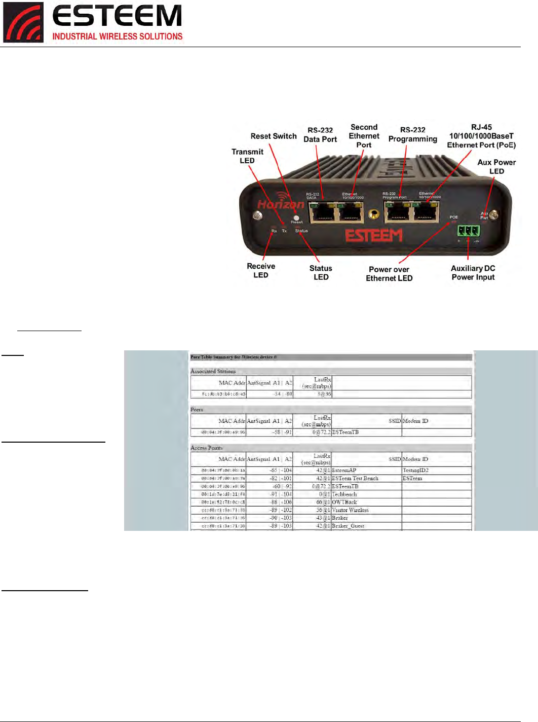
APPENDIXE
TROUBLESHOOTING
Revised: 06 Jan 2017 APX E-1 ESTeem Horizon Series
TestingCommunicationLink
AfteryouhaveconfiguredatleasttwooftheHorizonwirelessEthernetmodemsforoperation,youcanverifycommunicationwith
eachthefollowingsteps:
StatusLight
ThequickestsourceoflinkstatusistoviewtheStatus
LEDonthefaceoftheHorizon(Figure1).IftheStatus
lightissolid,theHorizonhasaconnectiontoanother
HorizonlistedinthePeerTable.
WirelessStatusScreen
Toviewdetailedinformationonthestatusofthe
communicationlink(suchasconnectionspeed,signal
strengthandlastupdatetime)youcanopenthe
WirelessStatusScreenfromtheWebInterface.After
presstheStatustabatthetopofthescreentheStatus:
SummarywillbedisplayedshowingthestatusofallportsandmemoryintheHorizon.UndertheWirelessStatusheadingclickon
theViewPeerTable(Figure2).
Peers‐ThePeerTablewill
displayallconnected
Horizonsconfiguredasa
PeerlinktothisESTeemby
theirWireless(WLAN)MAC
address.
ReceivedSignalStrength–
TheAntSignalcolumnwill
displaythereceivesignal
strengthforeachofthetwo
antennaports.Thefirst
antennaportislistedasA1
whilethesecond(receive
only)portislistedasA2.You
mayreceiveasignallevelon
A2althoughnoantennais
attached.ThissignalstrengthvalueislistedindBm.
LastRXandDataRate–Thisisthetimeofthelastreceiveddatapacket.Whenmonitoringthestatusmenu,itisimportanttonote
thetimethelasttransmissionwasupdatedsoyouarenotlookingat“stale”data.Avalueof0inthetimerepresentsacurrent
(lessthan1second)receivevalue.ThecurrentdatarateofthelastdatapacketreceivedwillalsobeshownbytheHorizon.The
speedisdisplayedinMbps.Forexample,inFigure2aLastRxvalueof0@72.2representsanRFpacketreceivedwithinthelast
secondrunningat72.2Mbps.
Note:TheESTeemHorizonusesspreadspectrumtechnologythatanalyzeseachdatapacketforsignalstrengthanddataquality
(strengthvs.noise).Thehigheryoursignal,themorebackgroundnoiseyoucansustainwithoutcausingdegradationinthedata
transfer.Thisisalsotrueforlowersignalstrengthswithaverylowbackgroundnoise.Thesevaluesareprovidedforguidanceand
Figure1:ConnectionStatusLight
Figure2:PeerStatus
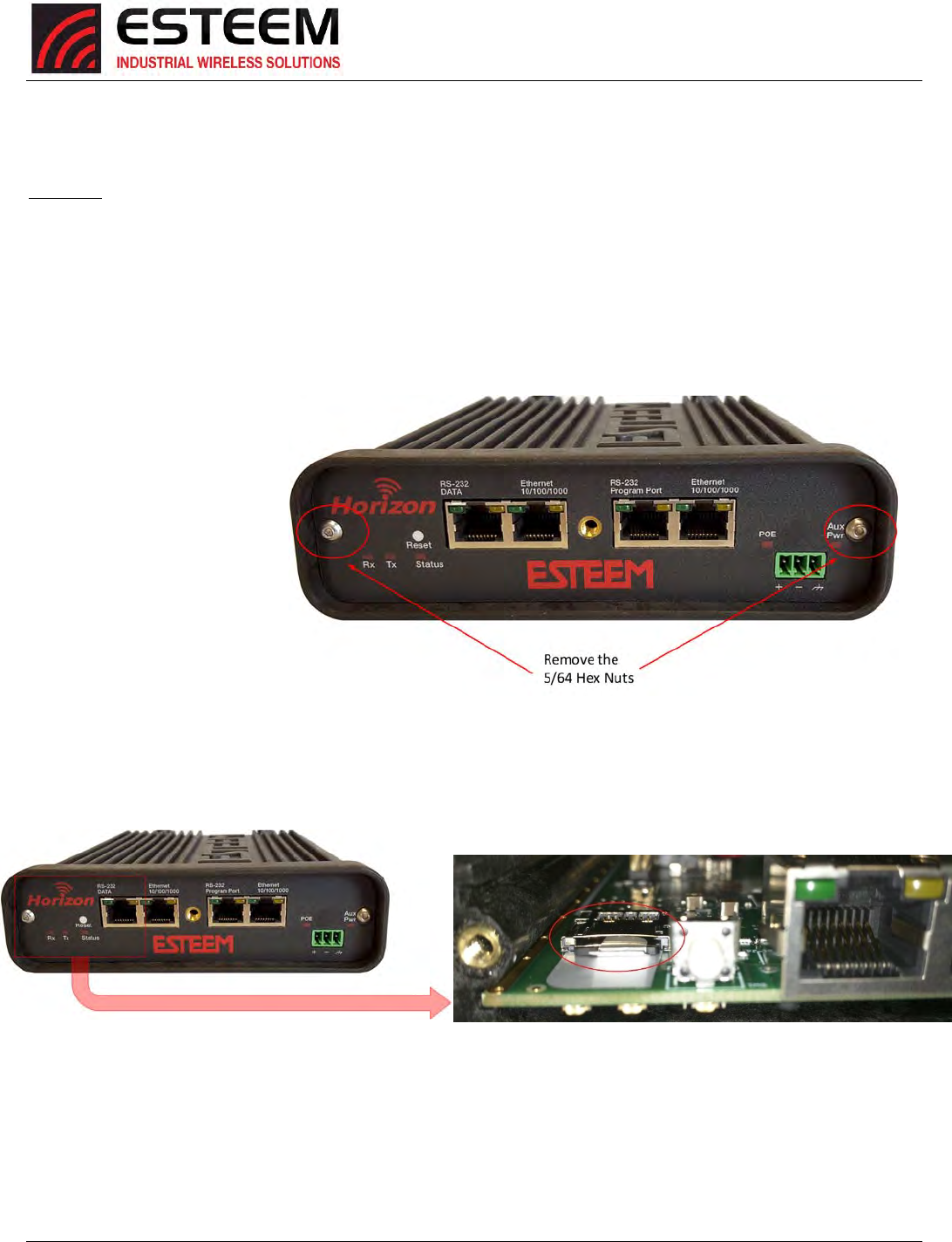
APPENDIXE
TROUBLESHOOTING
Revised: 06 Jan 2017 APX E-2 ESTeem Horizon Series
ifyouhaveanyquestionsaboutthevaluesinyourapplication,pleasecontactESTeemCustomerSupportat509‐735‐9092ore‐
mailyourapplicationtosupport@esteem.com.
ModemID–ThisisModemIDfortheoppositeESTeempeer.
CloningRadio
AnewfeatureintheHorizonSeriesradiosistheabilityto“clone”oneradiotoanotherbysimplychangingtheMicroSDmemory
module.Thisfeaturewillallowthecopyofallsettingsandidentifiers(Peers,SSID,Channel,IPAddress,SerialNumber,andeven
MACAddress)fromoneradiotoanotherradiosothataradiocanbereplacedinthefieldwithnoprogrammingrequired.The
radiodoesthisbysavingacopyofthesesettingstoamicroSDcardthatcanberemovedandplacedintoanotherHorizonSeries
radio.Bydefault,RadioCloningisenabledandallHorizonradioswillhaveacompatiblemicroSDcardpreinstalled.
Tocloneoneradiotoanother,
verifythetworadiosareofthe
samemodelandfirmwareversion.
Thisinformationcanbefoundon
the“Top”pageoftheWeb
ConfigurationToolorincludedon
theQualityAssurancepaperwork
shippedwitheachradio.Thefirst
steptoclonearadioistoremove
thefaceplatefromthefrontofthe
Horizonbyremovingthetwo5/64
hexnuts(Figure3).
Next,locatethemicroSDcardinstalledintheradio(Figure4).ThemicroSDcardcanbefoundbehindtheTX/RXLEDsnexttothe
resetswitch.ThemicroSDcardhasalockingmechanism.ToretrievethemicroSDcard,pressin(towardsthebackoftheradio)
firmlyandthenpulloutcard.(SeeFigure4).
Figure4:MemoryModuleLocation
OncetheHorizon’sMicroSDmodulehasbeenchanged,itwillbootasaclonedcopyofthereplacedradioandnoother
programmingisrequired.
Figure3:HorizonFrontPanel
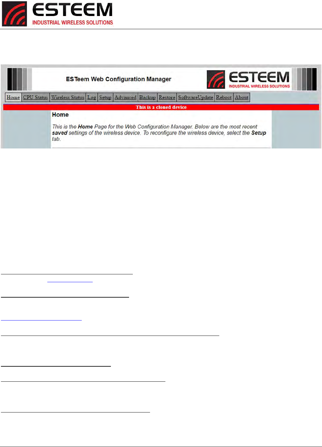
APPENDIXE
TROUBLESHOOTING
Revised: 06 Jan 2017 APX E-3 ESTeem Horizon Series
WhenconnectingtoaclonedradiothroughtheWebConfigurationManager,youwillnoticethe“Thisisacloneddevice”
warninglabelonallpagesoftheWebConfigurationTool.(SeeFig5).
Figure5:ClonedDeviceWarning
Toreverttheclonedradio’ssettingbackpriortobecomingaclone,selecttheAdvancedmenuthenselectCloningSetupandpress
Nextbuttonatthebottomofthepage.Fromthispageyouwillseea“removeclonedata”buttonthatwhenpressedwillremove
theclonedatafromBOTHtheradioandthemicroSDCard.
Ifatanypointchangesaremadetotheclonedradio’sconfigurationandsaved,the“Thisisacloneddevicewarning”warningwill
goawayandtheoptionofrevertingtoaprevioussavewillnolongerbeavailableintheAdvancedmenu.Theradiocanstillbe
resettoFactoryDefaultsandreprogrammedasrequired.
TROUBLESHOOTINGTIPS
General(ApplicabletoAllModesofOperation)
WheredoIfindthelatestfirmwareversionnumber?–WehavethelatestversionnumberoftheHorizonfirmwarelistedonthe
ESTeemWebsite(www.esteem.com)undertheHorizonproductpage.
HowandwhendoIupdatetheHorizonfirmware?‐YoushouldonlyupdatetheHorizonfirmwareifyouarehavingaspecific
problemanditisrecommendedthatyoudosobyESTeemCustomerSupportpersonnel.Alltheupdateinstructionsandfilesare
locatedontheESTeemFTPsiteatthefollowingaddress:
ftp://www.esteem.com/Horizon
DoallfirmwareversionshavetobethesametocommunicatebetweentheHorizon?–Itisnotnecessaryforallthefirmware
versionstobethesamerevisiontocommunication,butthelaterversionmayhaveaddedfeaturesthattheotherversionswillnot
recognize.
WhatcharactersarevalidforWEPKeyentry?‐OnlytheHexadecimalcharacters0‐9andA‐Farevalidforkeyentry.
WhatESTeemUtilityversionisrequiredtoprogramtheHorizon?–TheESTeemUtilityprogramisnotrequiredtoprogramthe
Horizon.TheHorizoncanbeprogrammedusinganyTerminalEmulationprogram(suchasWindowsHyperTerminal)andanyweb
browserprogram.
WhatisthespeedandduplexconfigurationontheHorizon–TheHorizonisanauto‐negotiationfull/half‐duplex10/100Base‐T
interface.Etheracross‐overorpatchcableissupported.

APPENDIXE
TROUBLESHOOTING
Revised: 06 Jan 2017 APX E-4 ESTeem Horizon Series
AccessPointMode
WirelessLANcardsarenotconnecting–VerifythatthewirelessLANcardsaresettoInfrastructureMode,haveamatchingSSID
(orESSIS)setthesameastheHorizonandthatallencryptioncodesarethesame.
MyWirelessLANcardshowsasolidconnection,butIcannotpassanydata–VerifytheencryptionandtheACLsettingonthe
HorizonmatchthewirelessLANcard.
AccessPointPeerMode
Howlongdoesittaketore‐establishtheWirelessEthernetNetwork?‐IfacommunicationlinkislostandtheWirelessNetwork
needstore‐establishtherepeaterroutes,thetimecantakeupto10seconds.
ShouldtheAPRepeaterModebeusedonmobileequipment?‐TheAPRepeatermodeshouldbeusedonequipmentthatwill
notchangetheRepeaterRouteasitmoves.Forexample,ifamobiledevicesuchasacranecancommunicatedirectlytoanother
ESTeemandwillnotloosethelinkinitstravel,theAPRepeaterModecouldbeused.IfthedevicerequirestwoESTeemHorizon’s
(BaseandRepeater)tomaintaincommunicationacrossitscompletetravel,theStationModesshouldbeusedonthemobile
device.TheproblemwillbeinthetimethatthemobileESTeemwilltaketotransferbetweenthetwosites.InAccessPoint
Repeatermodethetransfercantakeupto30seconds,whiletheEtherStationmodewilltransferwithoutapacketloss.
DoesWEPhavetobeused?–TheWEPdoesnothavetobeenabledforthemodemstocommunicate,butallmodemsmustbe
configuredthesameway.
Correctconfiguration,butcannotestablishcommunications.–Inadditiontothenetworkconfiguration,allHorizonmodems
configuredintheAPmodemustsharethesameSSIDandbeonthesamefrequencychannel.Themostlikelycauseoftheerror
istheWLANMACaddressisnotconfiguredinbothHorizon’srepeatertables.Ifonlyonesideisconfigured,everythingwillappear
tobecorrectbutnocommunicationwillfunction.
EtherStation
HowdoIaccesstheHorizonwebpageinEtherStationMode?TheHorizondoesnothaveanactivewebbrowserwhenconfigured
inEtherStationmode.YoumustaccesstheESTeemwiththeESTeemDiscoveryProgramorthroughtheRS‐232portafter
configurationinthismode.Tomonitorthelinkstatus,youcanusetheEtherStationStatusprogram.
WhatIPaddressdoIconfiguretheESTeeminEtherStationmode?–TheHorizonwillnothaveanIPaddressinEtherStationmode.
Icannotlinkmydeviceintothewirelessnetwork–VerifythattheMACaddressofthedeviceisexactlythesameasconfiguredin
theHorizon.TheMACaddressmusthavecolonsbetweenthevalues.
CanIconnectmyHorizoninEtherStationmodetoaHUBorEthernetSwitch?–No.Themodemmustbeconnecteddirectlyto
theEthernetdeviceforwhichitisprogrammed.InEtherStationmodetheHorizoncanonlyserviceONEEthernetdevice.
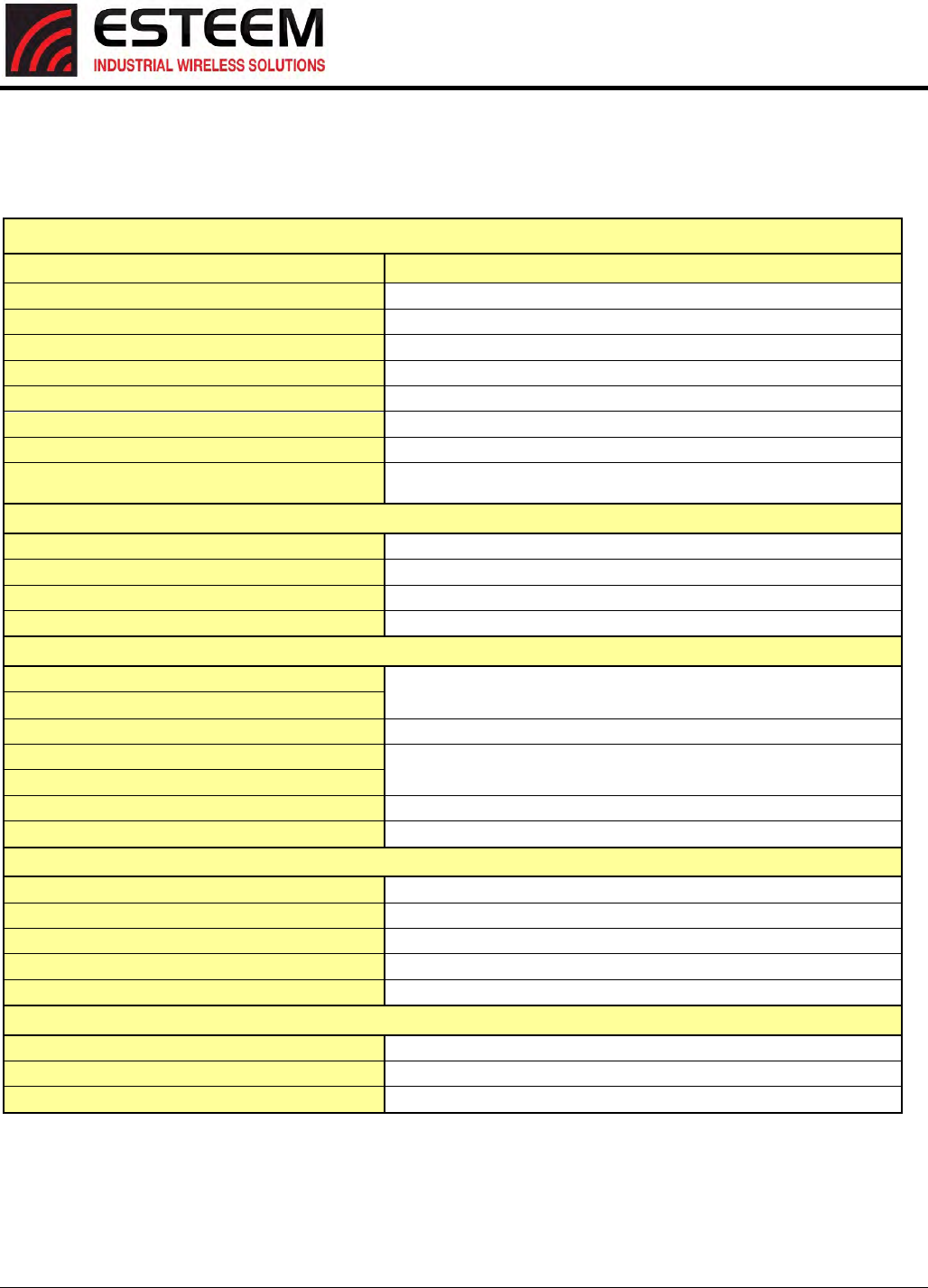
APPENDIXF
HORIZON2.4SPECIFICATIONS
Horizon 2.4 GHz Specifications
Revised: 25 Jan 17 APX F-1 ESTeem Horizon Series
ESTeemHorizon2.4GHzSpecifications
Transmitter/Receiver
FrequencyofOperation(SoftwareSelectable)2.412to2.462GHz(11‐channels)
RFDataRate1to150Mbps(20steps)
TxOutputPower(SoftwareSelectable)250to1000mW(Pk)(4‐levels)
TxOutputImpedance50ohms
RxSensitivity‐92to‐69dBm
FCCTypeAcceptanceENPHZN216AN
IndustryCanadaTypeAcceptance2163A‐216AN
LEDIndicatorsPower(On/Off)‐CarrierDetect(On/Off)‐Transmitter(On/Off)‐Receiver
(On/Off)
PowerRequirements
Receive600ma@12VDC
Transmit1.350A(Cont)3A(Peak)@12VDC
PoEPowerSupply (IEEE802.3at,30watts)(opt)
ExternalPowerInput10to28VDC@3A
Input/OutputConnectors
EthernetPort1(10/100)
RJ‐45Female
EthernetPort2(10/100)
802.11Compatibility802.11n/g/b
RS‐232CCommPort(2,400to115.2Kbaud)
RJ‐45Female
RS‐232CProgrammingPort(38,400,N,8,1)
AntennaInput/OutputsTNCReverseFemale
ExternalDCInputPowerMini‐Combicon,3pinfemale
Case
TemperatureRange‐30°to+60°C
Humidity95%Non‐condensing
Dimensions1.9in.Hx6.7in.Wx6.2in.L
Weight1.25lbs.
ProductWarranty1Year
Other
OutdoorPoleMt.Kit AA195PM(opt)
PoEPowerSupplyAA175.2(opt)
ExternalDCInputPowerConnectorAA195PP(opt)
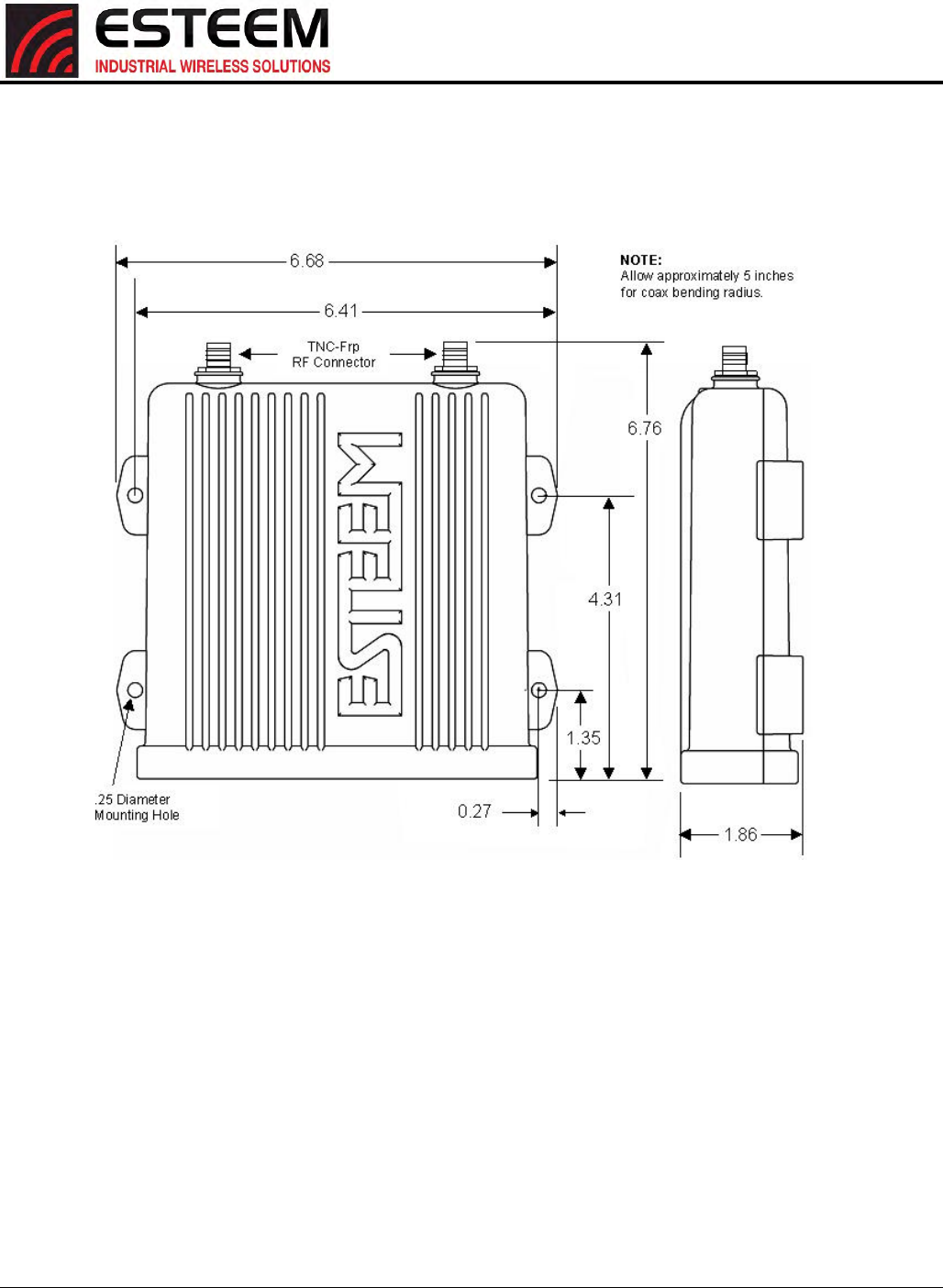
APPENDIXF
HORIZON2.4SPECIFICATIONS
HorizonCaseSpecifications
Revised: 25 Jan 17 APX F-2 ESTeem Horizon Series
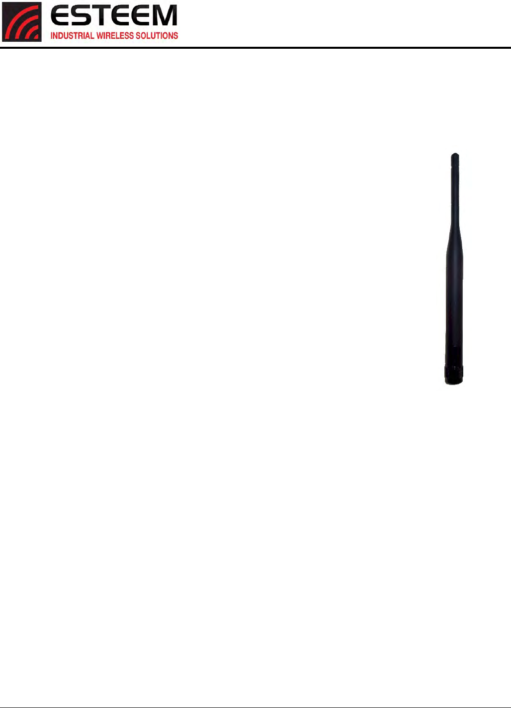
APPENDIXF
HORIZON2.4SPECIFICATIONS
AntennaSpecifications
Revised: 25 Jan 17 APX F-3 ESTeem Horizon Series
Model:AA20DMEg
Applications:Model195Egdirectcasemount
AntennaType:Omni‐Directional,Sleevedipole
Frequency:2400to2485MHz
Polarization:Vertical
Impedance:50ohms
Gain:5dBi(3dBd)
VSWR:<2:1
Power:10W
FrontToBackRatio:n/a
HorizontalBeamwidth:n/a
VerticalBeamwidth:n/a
AntennaMaterial:PolyurethanePlasticRadome
RecommendedMountingHardware:n/a
AntennaConnector:TNC‐RMale
Flexibility:+/‐20
AntennaEnvelope:8.28in.lengthby.54in.width
Temperature:‐40to+70C
Weight:33grams
ModelAA20DMEg
Caution
Omni-directional antenna
should not be located within
24 cm of personnel.
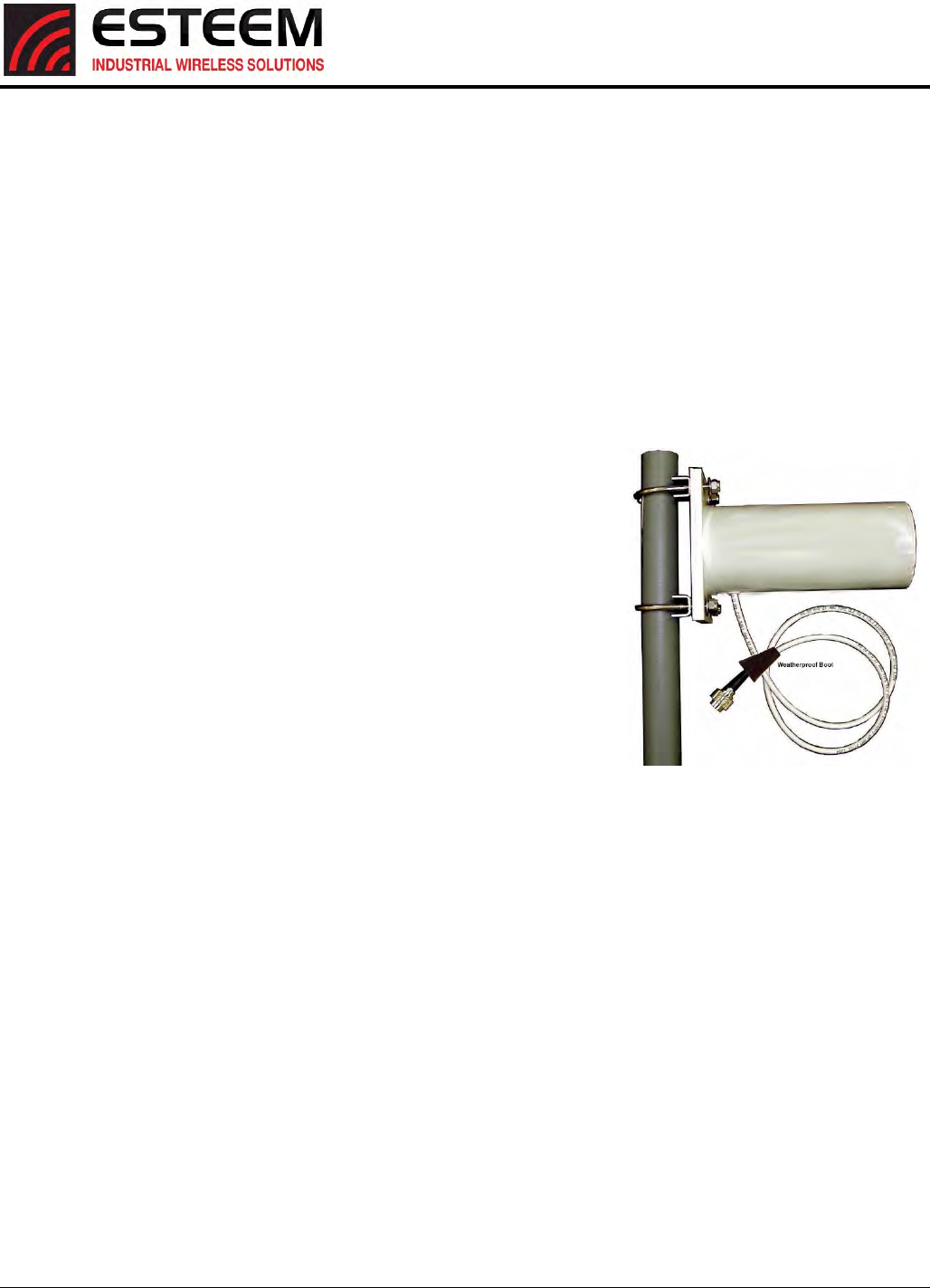
APPENDIXF
HORIZON2.4SPECIFICATIONS
AntennaSpecifications
Revised: 25 Jan 17 APX F-4 ESTeem Horizon Series
ModelNo:AA203Eg
AntennaType:Directional,DCgrounded
Applications:Fixedbase.
Frequency:2400to2485MHz
Polarization:VerticalorHorizontal
Impedance:50ohms
Gain:6dBi(4dBd)
VSWR:<1.5
FronttoBackRatio:>23dB
HorizontalBeamwidth: 55degrees@½power
VerticalBeamwidth: 55degrees@½power
AntennaMaterial:SealedinUVstablefiberglassenclosedradome
MountingHardware: StainlesssteelUbolts(included)formountingup
to15/8in.diameterpipe.
AntennaConnector:TNC‐RMalewith36in.pigtail
MaximumPowerInput:5Watts
AntennaEnvelope:4.5in.lengthby3in.diameter
Windload(RWV):125mph
LateralThrustat
RatedWind:5.8lbs.
WindSurfaceArea:0.060ft2
Weight:1lbs.
ModelAA203Eg
Caution
To comply with the FCC
exposure compliance
requirements, a separation
distance of at least 24 cm
must be maintained between
the antenna and all persons.
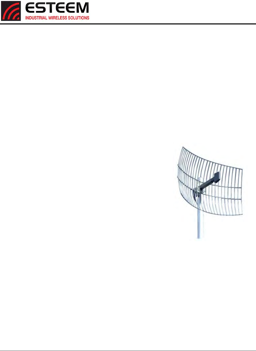
APPENDIXF
HORIZON2.4SPECIFICATIONS
AntennaSpecifications
Revised: 25 Jan 17 APX F-5 ESTeem Horizon Series
ModelNo:AA204Eg.1
Applications: Fixedbasemounting
AntennaType:2.4GHzISM,Directional,DCGrounded,ParabolicGrid
Frequency:2400‐2485MHz
Polarization:VerticalorHorizontal
Impedance:50ohms
Gain:15dBi(13dBd)nominal
VSWR:<1.5:1nominal
FronttoBackRatio: >24dB
HorizontalBeamwidth: 16degrees@½power
VerticalBeamwidth: 11degrees@½power
AntennaMaterial:Zincplatedcoldrolledsteelwithpolyesterpower
coatfinish
RecommendedMounting
Hardware:StandardU‐boltsteelmastclampcompletewith
mountinghardware.Designedformastsofupto
2.5in.O.D.
AntennaConnector: TNC‐RMalewith36in.pig‐tail
MaximumPowerInput: 10Watts
WindSurvival:100mph
WindLoad:16mph
AntennaEnvelope: 34in.lengthby17in.widthby11in.height
Weight:3lbs.
UseoftheAA204Eg.1,directionalantennaislimitedtofixedpoint‐to‐pointapplicationsonly.InaccordancewithFCC
Section15.247(b)iii,thisantennamustbeprofessionallyinstalled.Theinstallermustensurethesystemisused
exclusivelyforfixed,point‐to‐pointapplicationsandtheESTeemModel195Egissetfor0.25Wattsoutputpower(Power
Level=Min).
ModelAA204Eg.1
Caution
To comply with the FCC exposure
compliance requirements, a
separation distance of at least 50 cm
must be maintained between the
antenna and all persons.
APPENDIXG
HORIZON900SPECIFICATIONS
Horizon900MHzSpecifications
Revised: 25 Jan 17 APX G-1 ESTeem Horizon Series
Transmiter/Receiver
Frequency of Operation (Software Selectable) 902-928 MHz (4-channels)
RF Data Rate 1 to 72.2 Mbps
Tx Output Power (Software Selectable) 1 Watt (30dBm)
Channel Bandwidth 5 MHz, 10 MHz or 20 MHz
Tx Output Impedance 50 ohms
Rx Sensitivity -97 to -68 dBm
FCC Type Acceptance ENPHZN216AD
Industry Canada Type Acceptance 2163A-216AD
LED Indicators Power (On/Off) - Carrier Detect (On/Off) - Transmitter (On/Off) - Reveiver (On/Off)
Power Requirements
Receive 600ma @ 12 VDC
Transmit 1.350A (Cont) 3A (Peak) @ 12 VDC
PoE Power Supply (IEEE 802.3at,30 watts) (opt)
External Power Input 10 to 16 VDC @ 3A
Input/Output Connectors
Ethernet Port 1 (10/100/1000)
Ethernet Port 2 (10/100/1000)
802.11 Compatibility n/a
RS-232C Comm Port (2,400 to 115.2 K baud)
RS-232C Programming Port (38,400, N, 8, 1)
Antenna Input/Outputs TNC Reverse Female
External DC Input Power Mini-Combicon, 3 pin female
Case
Temperature Range -30° to +60° C
Humidity 95% Non-condensing
Dimensions 1.9 in. H x 6.7 in. W x 6.2 in. L
Weight 1.25 lbs.
Product Warranty 1 Year
Other
Outdoor Pole Mt. Kit AA195PM (opt)
PoE Power Supply AA175.2 (opt)
RJ-45 Female
RJ-45 Female
ESTeem Horizon 900 Specifications
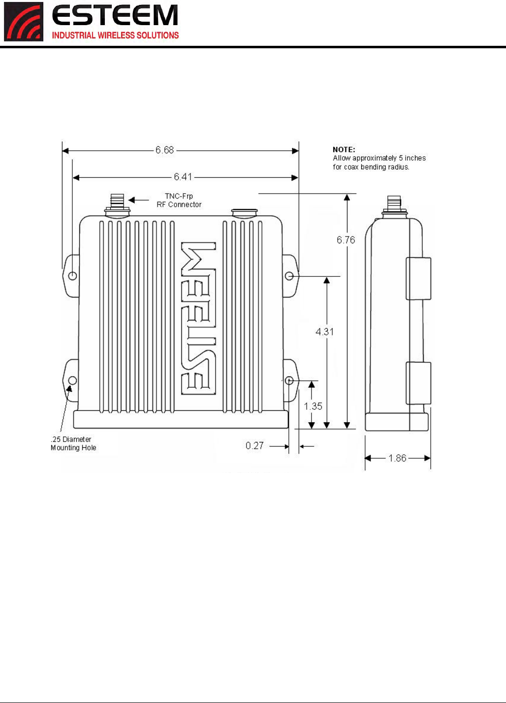
APPENDIXG
HORIZON900SPECIFICATIONS
Horizon900MHzCaseSpecifications
Revised: 25 Jan 17 APX G-2 ESTeem Horizon Series
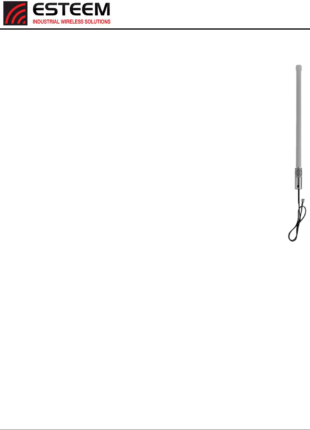
APPENDIXH
HORIZON900SPECIFICATIONS
AntennaSpecifications
Revised: 25 Jan 17 APX H-3 ESTeem Horizon Series
Model No: AA20Es900
Antenna Type: Omni Directional, DC Grounded
Applications: Fixed base
Frequency: 902 to 928 MHz
Polarization: Vertical
Impedance: 50 ohms
Gain: 7 dBi (5 dBd)
VSWR: 1.5:1 Typical
Front to Back Ratio: n/a
Horizontal Beamwidth: n/a
Vertical Beamwidth: 22 degrees @ ½ power
Antenna Material: Brass radiator, UV inhibited
fiberglass enclosed
Mounting Hardware: Base to Mast, Supplied.
Maximum Power Input: 150 Watts
Wind Survival: 100 mph
Bending Moment: 14.2 ft-lbs. @ 100 mph
Antenna Connector: TNC-R Male with 36in. pig-tail.
Antenna Envelope: 48 in. L x 1-5/16 in. Dia.
Weight: 1.75 lbs.
Model AA20Es900
Caution
To comply with the FCC
exposure compliance
requirements, a separation
distance of at least 23 cm
must be maintained between
the antenna and all persons.
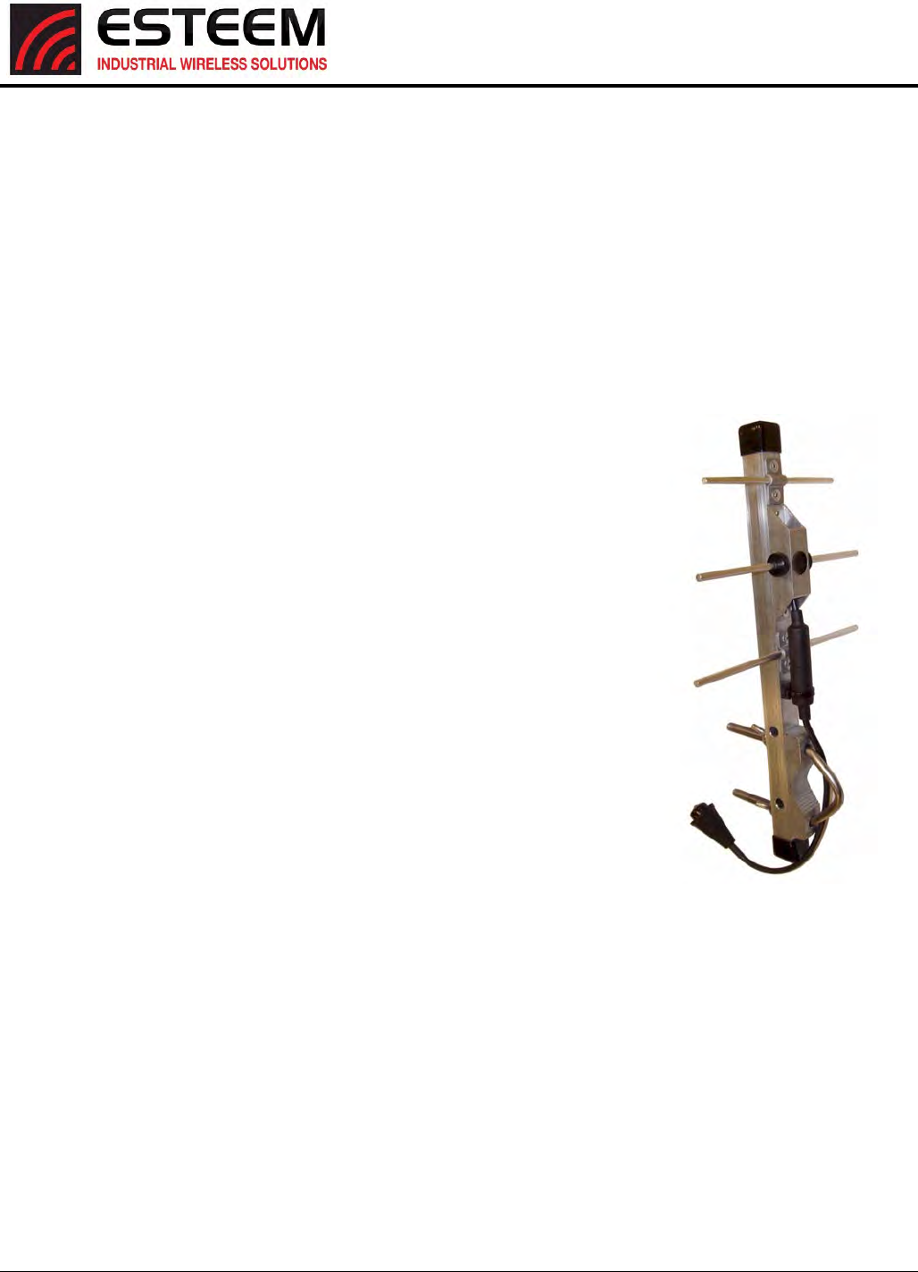
APPENDIXH
HORIZON900SPECIFICATIONS
AntennaSpecifications
Revised: 25 Jan 17 APX H-4 ESTeem Horizon Series
Model No: AA203Es900
Antenna Type: Directional, DC grounded
Applications: Fixed base.
Frequency: 902 to 928 MHz
Polarization: Vertical or Horizontal
Impedance: 50 ohms
Gain: 7 dBi (5 dBd)
VSWR: < 1.5:1 Nominal
Front to Back Ratio: > 16 dB
Horizontal Beamwidth: 130 degrees @ ½ power
Vertical Beamwidth: 70 degrees @ ½ power
Antenna Material: Aluminum
Mounting Hardware: Heavy duty U bolts for mounting up to 2.0 in. pipe
(included).
Antenna Connector: TNC-R Male with 2 ft. pigtail with ESTeem
weatherproof boot.
Maximum Power Input: 50 Watts
Antenna Envelope: 1.1 ft. length by 6 in. width
Windload (RWV): 150 mph
Wind Surface Area: .11 ft²
Weight: 1 lbs.
Caution
To comply with the FCC
exposure compliance
requirements, a separation
distance of at least 23 cm
must be maintained between
the antenna and all persons.
APPENDIXH
HORIZON4.9SPECIFICATIONS
Horizon4.9GHzSpecifications
Revised: 25 Jan 17 APX H-1 ESTeem Horizon Series
Frequency of Operation (Software Selectable) 4.960 to 4.980 GHz (7-channels)
RF Data Rate 1 to 72.2 Mbps
Tx Output Power (Software Selectable) 24 dBm (RMS)
Tx Output Impedance 50 ohms
Channel Bandwidth 5 MHz, 10 MHz or 20 MHz
Rx Sensitivity -106 to -71 dBm
FCC Type Acceptance ENPEST216AP
Industry Canada Type Acceptance Not Approved
LED Indicators Power (On/Off) - Carrier Detect (On/Off) - Transmitter (On/Off) - Reveiver (On/Off)
Power Requirements
Receive 600ma @ 12 VDC
Transmit 1.350A (Cont) 3A (Peak) @ 12 VDC
PoE Power Supply (IEEE 802.3at,30 watts) (opt)
External Power Input 10 to 16 VDC @ 3A
Input/Output Connectors
Ethernet Port 1 (10/100/1000)
Ethernet Port 2 (10/100/1000)
802.11 Compatibility n/a
RS-232C Comm Port (2,400 to 115.2 K baud)
RS-232C Programming Port (38,400, N, 8, 1)
Antenna Input/Outputs TNC Female
External DC Input Power Mini-Combicon, 3 pin female
Case
Temperature Range -30° to +60° C
Humidity 95% Non-condensing
Dimensions 1.9 in. H x 6.7 in. W x 6.2 in. L
Weight 1.25 lbs.
Product Warranty 1 Year
Other
Outdoor Pole Mt. Kit AA195PM (opt)
PoE Power Supply AA175.2 (opt)
External DC Input Power Connector AA195PP (opt)
Transmiter/Receiver
RJ-45 Female
RJ-45 Female
ESTeem Horizon 4.9 Specifications
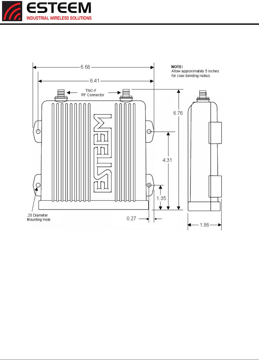
APPENDIXH
HORIZON4.9SPECIFICATIONS
Horizon4.9GHzCaseSpecifications
Revised: 25 Jan 17 APX H-2 ESTeem Horizon Series
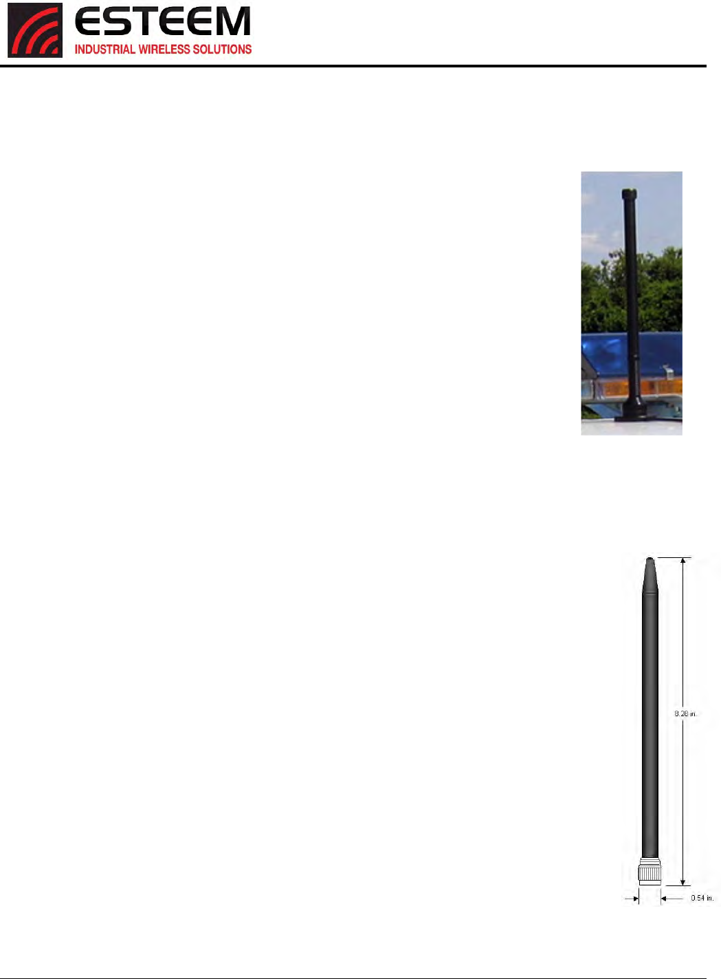
APPENDIXH
HORIZON4.9SPECIFICATIONS
AntennaSpecifications
Revised: 25 Jan 17 APX H-3 ESTeem Horizon Series
ModelNo:AA191Ep
AntennaType:Omni‐Directional,VehicleMount
Applications:Mobile
Frequency:4.9‐5.0GHz
Polarization:Vertical
Impedance:50ohms
Gain:5.5dBi
VSWR:<1.5
FronttoBackRatio:n/a
HorizontalBeamwidth: n/a
VerticalBeamwidth: n/a
AntennaMaterial:BlackRadome
MountingHardware:BaseIncluded
AntennaConnector:TNCMale
AntennaEnvelope:12in.lengthby1.75inwidth
Weight: .08lbs.
Model:AA20DMEp
Applications: Model195Epdirectcasemount
AntennaType: Omni‐Directional,Sleevedipole
Frequency: 4.9‐5.0GHz
Polarization: Vertical
Impedance: 50ohms
Gain:5.5dBi(3.5dBd)
VSWR:<2:1
Power:10W
FrontToBackRatio: n/a
HorizontalBeamwidth: n/a
VerticalBeamwidth:n/a
AntennaMaterial: PolyurethanePlasticRadome
RecommendedMountingHardware:n/a
AntennaConnector: TNCMale
Flexibility:+/‐20
AntennaEnvelope: 8.28in.lengthby.54in.width
Temperature:‐40to+70C
Weight: 33grams
Model AA191Ep
ModelAA20DMEp
Caution
Omni-directional antenna
should not be located within
20 cm of personnel.
Caution
Omni-directional antenna
should not be located within
20 cm of personnel.
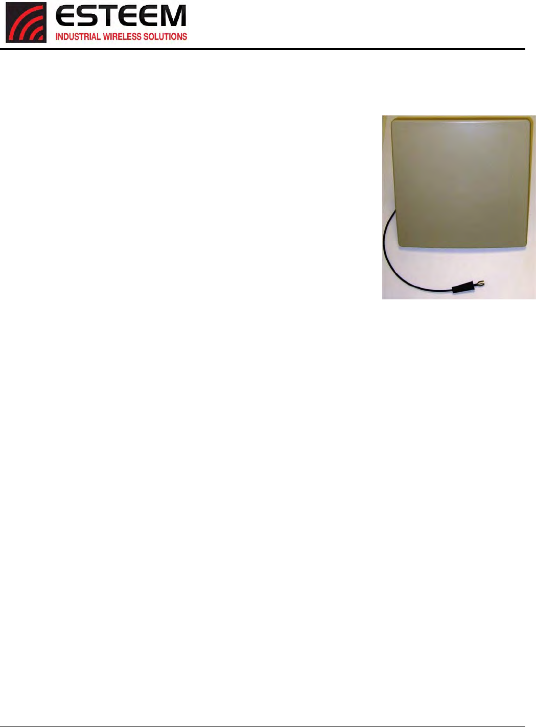
APPENDIXH
HORIZON4.9SPECIFICATIONS
AntennaSpecifications
Revised: 25 Jan 17 APX H-4 ESTeem Horizon Series
ModelNo:AA204Ep
Applications: Fixedbasemounting
AntennaType:4.9GHz,Directional,DCGrounded,PanelAntenna
Frequency:4.9‐5.9GHz
Polarization:VerticalorHorizontal
Impedance:50ohms
Gain:22dBi(20dBd)nominal
VSWR:<1.5:1nominal
FronttoBackRatio: >‐35dB
HorizontalBeamwidth: 9degrees@½power
VerticalBeamwidth: 9degrees@½power
AntennaMaterial:WhiteUSResistantPolypropylene
RecommendedMounting
Hardware:AdjustableMountingBracketprovidedforwallmountingor
mastsbetween1inand2.75in.O.D..
AntennaConnector: TNC‐Malewith18in.pig‐tailandweatherboot
MaximumPowerInput: 20Watts
AntennaEnvelope: 14.5in.lengthby14.5in.heightby1.75in.depth
Weight:3.5lbs.
ModelAA204Ep
Caution
To comply with the FCC exposure
compliance requirements, a
separation distance of at least 60 cm
must be maintained between the
antenna and all persons.
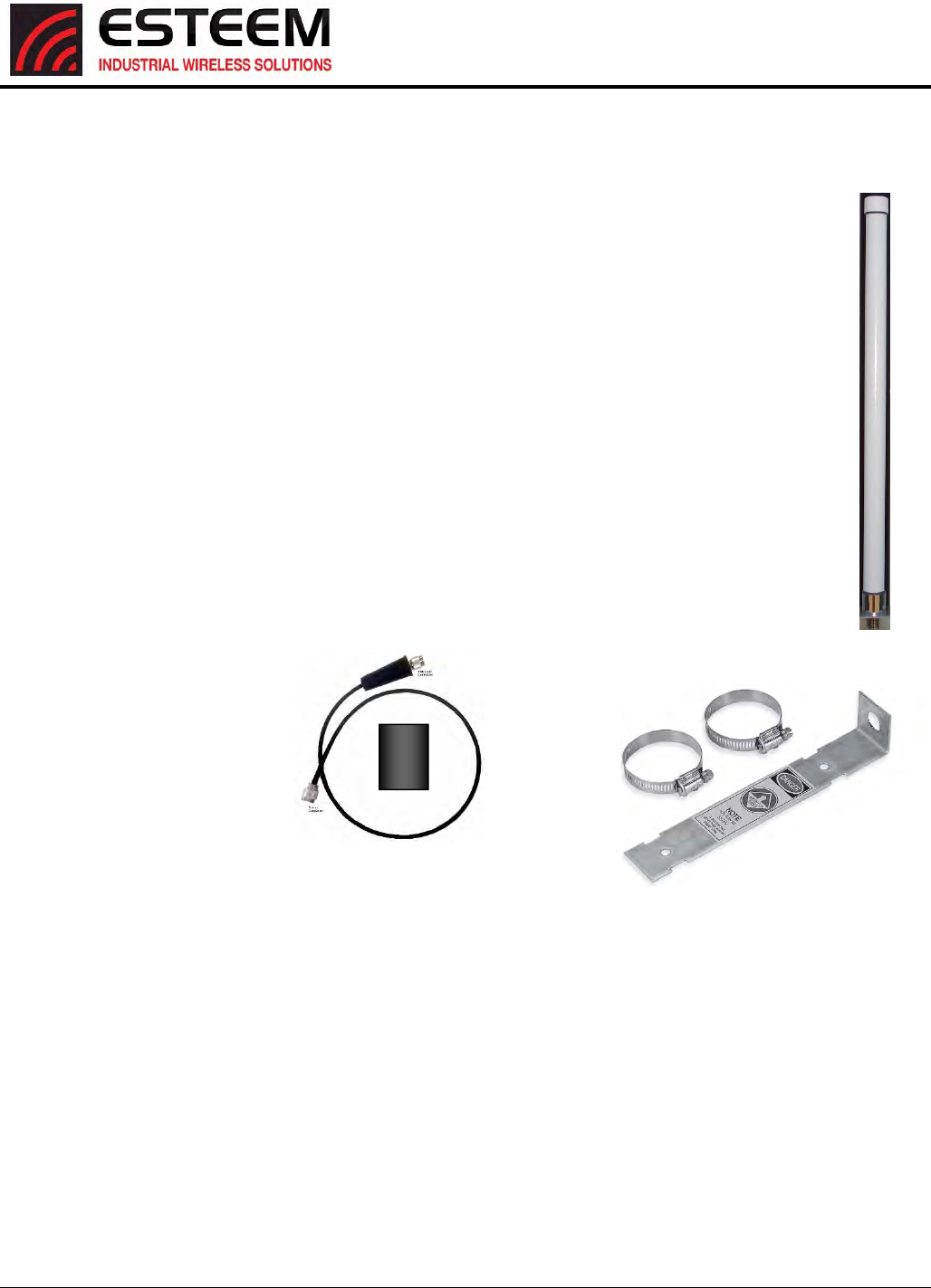
APPENDIXH
HORIZON4.9SPECIFICATIONS
AntennaSpecifications
Revised: 25 Jan 17 APX H-5 ESTeem Horizon Series
ModelNo:AA20Ep
Application:Fixedbasemounting
AntennaType: Omni‐Directional,DCgrounded
Frequency: 4940‐4990MHz
Polarization: Vertical
Impedance: 50ohms
Gain:10dBi(8dBd)
VSWR:2:1maximum
VerticalBeamwidth: 8.5degrees
RecommendedMountingHardware:FB2Bracket
AntennaConnector:TNC‐MaleConnectoronCable
MaximumPowerInput: 20Watts
WindSurvival: 150mph
AntennaHeight: 17.31in.
BendingMoment: 30lbs.
Radome: UVProtectedAcrylonitrileStyreneAcrylate
Weight: 5.9oz
Caution
To comply with the FCC
exposure compliance
requirements, a separation
distance of at least 20 cm must
be maintained between the
antenna and all persons.
ESTeemModel195EpInterfaceCable,EST
P/NAA241LMR,N‐male/TNC‐male
connectorsandMasticPadfor
weatherproofing
PoleMounting
BracketIncluded
APPENDIXI
HORIZON5.8SPECIFICATIONS
Horizon5.8GHzSpecifications
Revised: 25 Jan 17 APX I-1 ESTeem Horizon Series
Frequency of Operation (Software Selectable) 5.745 to 5.825 GHz (17-channels)
RF Data Rate 6 to 300 Mbps
Tx Output Power (Software Selectable) 250 mW (24dBm)
Channel Bandwidth 5 MHz, 10 MHz, 20 MHz or 40 MHz
Tx Output Impedance 50 ohms
Rx Sensitivity -93 to -73 dBm
FCC Type Acceptance TV7R11E5HND
Industry Canada Type Acceptance Not Approved
LED Indicators Power (On/Off) - Carrier Detect (On/Off) - Transmitter (On/Off) - Reveiver (On/Off)
Receive 250 ma @ 12 VDC
Transmit 1250 ma @ 12 VDC
PoE Power Supply (IEEE 802.3at,30 watts) (opt)
External Power Input 10 to 16 VDC @ 1250 ma
Ethernet Port 1 (10/100/1000)
Ethernet Port 2 (10/100/1000)
802.11 Compatibility 802.11n/a
RS-232C Comm Port (2,400 to 115.2 K baud)
RS-232C Programming Port (38,400, N, 8, 1)
Antenna Input/Outputs TNC Reverse Female
External DC Input Power Mini-Combicon, 3 pin female
Temperature Range -30° to +60° C
Humidity 95% Non-condensing
Dimensions 1.9 in. H x 6.7 in. W x 6.2 in. L
Weight 1.25 lbs.
Product Warranty 1 Year
Outdoor Pole Mt. Kit AA195PM (opt)
PoE Power Supply AA175.2 (opt)
GPS Location Optional (Factory Installed)
Other
RJ-45 Female
RJ-45 Female
ESTeem Horizon 5.8 Specifications
Transmiter/Receiver
Power Requirements
Input/Output Connectors
Case
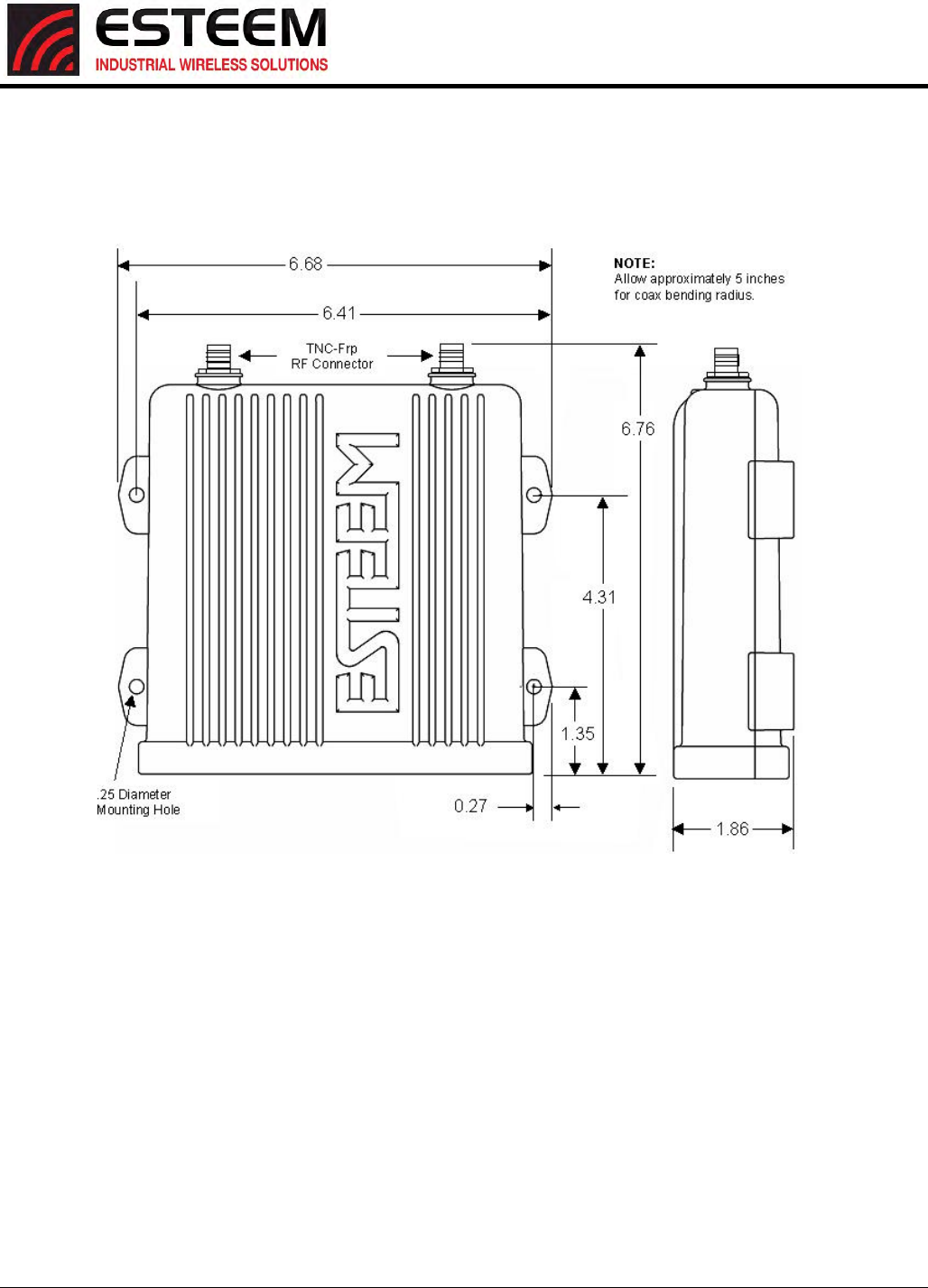
APPENDIXI
HORIZON5.8SPECIFICATIONS
Horizon5.8GHzCaseSpecifications
Revised: 25 Jan 17 APX I-2 ESTeem Horizon Series
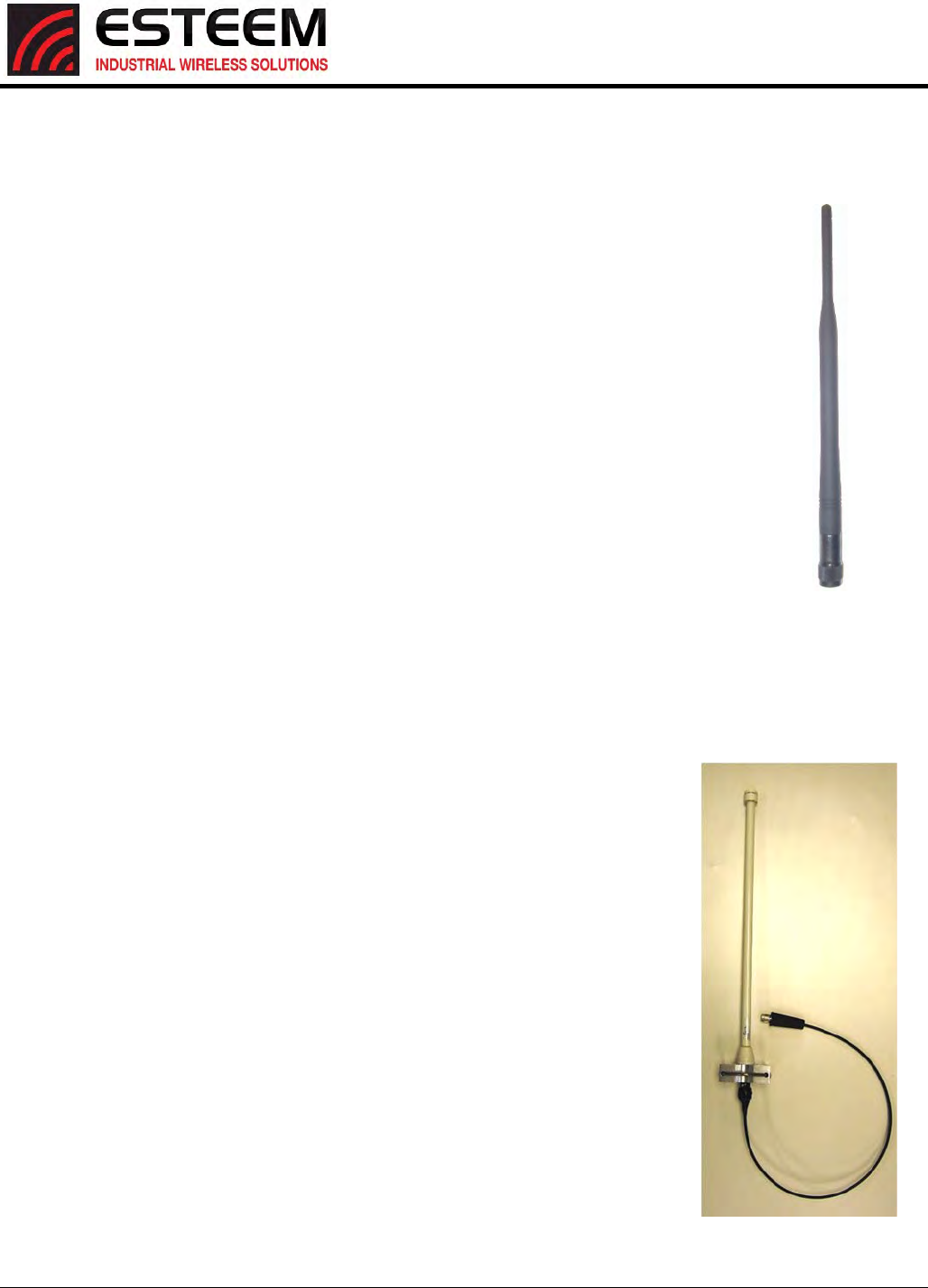
APPENDIXI
HORIZON5.8SPECIFICATIONS
AntennaSpecifications
Revised: 25 Jan 17 APX I-3 ESTeem Horizon Series
Model:AA20DMEa
Applications: Model195Eadirectcasemount
AntennaType: Omni‐Directional,Sleevedipole
Frequency: 5.735to5.835GHz
Polarization: Vertical
Impedance: 50ohms
Gain:4.5dBi(2.5dBd)
VSWR:<1.5:1
Power:10W
FrontToBackRatio: n/a
HorizontalBeamwidth: n/a
VerticalBeamwidth: n/a
AntennaMaterial: PolyurethanePlasticRadome
RecommendedMountingHardware:n/a
AntennaConnector:TNC‐RMale
Flexibility: +/‐20
AntennaEnvelope: 7.36in.lengthby.51in.width
Temperature: ‐20to+65C
Weight: 28.4grams
ModelNo: AA20Ea
AntennaType: OmniDirectional,DCGrounded
Applications: Fixedbase
Frequency: 5.725‐5.825GHz
Polarization: Vertical
Impedance: 50ohms
Gain:10dBi(8dBd)
VSWR:1.5:1Typical
VerticalBeamwidth: 6degrees@½power
RecommendedMountingHardware:PoleMountingBracket,Supplied
AntennaConnector: TNCmalereversepolaritywith
18in.pigtailandweatherproofboot
MaximumPowerInput: 25Watts
WindSurvival: 125mph
AntennaEnvelope: 20.2in.Lx1.25in.
EquivalentFlatPlateArea:.06sq.ft
LateralThrustatRatedWind:5.2lbsfeet
Radome: WhiteUVresistantfiberglass
Weight: 0.5lbs.
AA20DMEa
Caution
To comply with the FCC
exposure compliance
requirements, a separation
distance of at least 113 cm
must be maintained
between the antenna and
all persons.
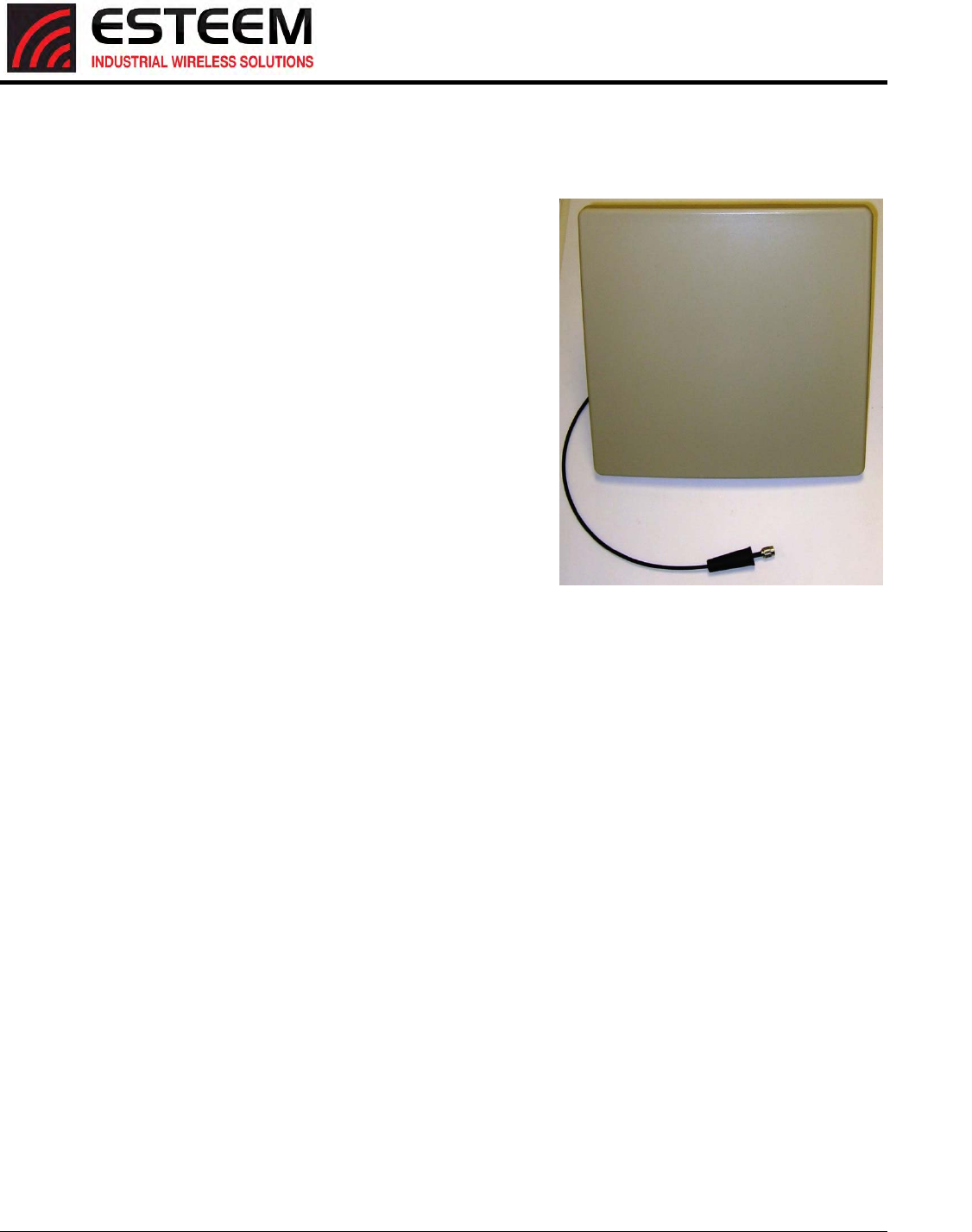
APPENDIXI
HORIZON5.8SPECIFICATIONS
AntennaSpecifications
Revised: 25 Jan 17 APX I-4 ESTeem Horizon Series
ModelNo: AA205Ea
Applications: Fixedbasemounting
AntennaType: Directional,LinearPolarizedPanel,DCgrounded
Frequency: 5.725‐5.875GHz
Polarization: VerticalorHorizontal
Impedance: 50ohms
Gain:22dBi(20dBd)nominal
VSWR:<1.5:1nominal
FronttoBackRatio: ≥25dB
HorizontalBeamwidth: 9degrees@½power
VerticalBeamwidth: 9degrees@½power
AntennaMaterial: WhiteUVResistantPolypropylene
RecommendedMountingHardware:AdjustableMountingBracket
providedforwallmountingormastsbetween1inand2.75in.O.D.
AntennaConnector: TNCmalereversepolaritywith18in.pig‐tail
andweatherproofboot.
MaximumPowerInput: 20Watts
AntennaEnvelope: 14.5in.lengthby14.5in.heightby1.75in.
depth
OperatingTemperature:‐40to+85F.
Weight: 3.5lbs.
Caution
To comply with the FCC
exposure compliance
requirements, a separation
distance of at least 113 cm
must be maintained
between the antenna and
all persons.