Electronics Tomorrow 745290403 433MHz RF Transmitter User Manual M059 M
Electronics Tomorrow Ltd. 433MHz RF Transmitter M059 M
User Manual
INSTRUCTION MANUAL
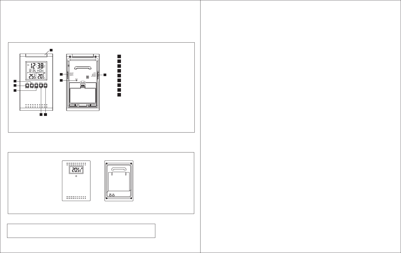
Locations of Control
Main Unit (Receiver)
HR/RE-SYNC BUTTON
MINUTE/CLEAR BUTTON
YEAR/ MAX/MIN BUTTON
MONTH/ 12/24 BUTTON
DATE/ °C/°F BUTTON
SNOOZE/ALARM ON/OFF SWITCH
RESET BUTTON
LOCK/ALARM/TIME/CAL SWITCH
SNOOZE/LIGHT BUTTON
A
B
C
D
E
F
G
H
I
Model 724A
Feature
• Calendar with day of the week display from January 1, 2003 to December 31, 2069
• Hour and minute display
• 12 or 24-hour format
• Indoor temperature and remote temperature
• Centigrade or Fahrenheit readout
• Clock operating temperature from 0°C to 50°C ( 32°F to 122°F )
• Indoor, Outdoor Temperature measuring range from -50°C to 70°C (-58°F to 158°F )*
• Temperature resolution 0.1°C
*If using the wireless transmitter with temperature below 32°F or above 122°F, user are
recommended to use Lithium battery to enhance batteries life.
Before You Begin
To ensure proper functioning of the RF Thermo Clock, please follow this set up procedure.
• Insert batteries for main unit ( Refer to instructions for battery installation ).
• Place the main unit as close as possible next to the remote unit and insert batteries for the
remote unit.
• Position the remote unit and main unit within effective transmission range, which in usual
circumstances is 20 to 30 meters.
Note that the effective range is affected by the building materials and where the main and
remote unit are positioned. Try various setup for the best results.
Batteries Installation
Batteries installation of the main unit
• Insert 2 "AA" batteries in polarity (+) and (-) as indicated
• Close the battery cover
• The low battery icon will show in the clock window when your batteries need replacing
Batteries installation of remote unit
• Insert 2 "AA" size batteries in proper polarity (+) and (-) as indicated
• Close the battery door
Warning : Do not mix old and new batteries
Do not mix alkaline, standard (carbon-zinc), or rechargeable (nickel cadmium)
batteries.
Size: 140mm(W) x 177mm(H) total 8 pages (M059) #9306 P.2 M059P.1
•The configuration of your clock may differ somewhat from that shown in the illustration.
•"AA" or "AAA" size battery. This clock may use more than one piece of battery. Please refer to the
engraved battery marks inside the battery compartment for the correct battery type.
A
Model 7452
Remote Unit (Transmitter)
S N O O Z E / L I G H T
H
B
C
D E
G
F
I

M059 M059
Do not touch any other buttons or settings on your clock. It will automatically receive
the remote temperature.
Getting Started
Upon power up of the remote unit ( or pressing the reset button ), the temperature RF signal
is immediately sent to the main unit. The main unit attempts to receive the RF temperature
signal for 5 minutes. The main unit refreshes the RF temperature every 3 minutes.
Check IN / REMOTE Temperature
The indoor temperature is displayed on the IN temperature field and the remote
temperature will be displayed on the REMOTE temperature field.
If the RF temperature signal is not received within 5 minutes after power up of the main unit
(or pressing the reset button), blank "---" will appear in the outdoor temperature window of
the main unit. In this case, press the HR/SYNC button of the main unit. The main unit will
attempt outdoor temperature reception for another 6 minutes.
After the remote temperature shows in the lower LCD panel, place the remote unit outside
in a shaded, dry area to protect it as if under an umbrella.
Try relocating the unit if the main unit does not display the remote temperature after 6
minutes.
Maximum and Minimum IN / REMOTE Temperature
The maximum and minimum recorded temperature readings will automatically be stored in
the memory.
Press the Max/Min button once to display the indoor maximum and minimum record. Press
the button again to show the REMOTE maximum and minimum record. The respective
indicators, IN and REMOTE will be displayed.
To clear the memory, press CLEAR when the maximum and minimum temperature records
are shown, it will clear the record of the shown temperature field.
Clock Set
1.Slide the LOCK/ALM/TIME/CAL switch to TIME position. The clock time blinks.
2.To set the time, press the HR/SYNC and MIN/CLEAR buttons until the desired time
appear on the display.
3.Slide the switch to LOCK position.
Alarm Set
1.Slide the LOCK/ALM/TIME/CAL switch to ALM position. The alarm time blinks.
2.To set the alarm time, press the HR/SYNC and MIN/CLEAR buttons until the desired
alarm time appear on the display.
3.Slide the switch to LOCK position.
Calendar Set
1.Slide the LOCK/ALM/TIME/CAL switch to CAL position. The calendar date blinks.
2.To set the calendar date, press the MONTH 12/24, DATE/°C/°F and YEAR/MAX/MIN
button until the desired calendar date appear on the display.
3.Slide the switch to LOCK position.
To Activate Alarm Function
1.Slide the SNZ/ALARM ON/OFF switch to ON position, the sign will appear on the time
display. The alarm function is activated.
2.When the alarm sounds, press the Snooze/Light button. The alarm will sound the same
time of the next day.
3.To deactivate the alarm function, slide the SNZ/ALARM ON/OFF switch to OFF position.
To Activate the snooze alarm
1.Slide the SNZ/ALARM ON/OFF switch to SNZ position. The sign and Zz will appear
on the time display.
2.When the alarm sounds, press the Snooze/Light button. The alarm will sound again in
approximately 5 minutes. You may repeat this function for 10 minutes.
3.To deactivate the snooze alarm, slide the SNZ/ALARM ON/OFF switch to the OFF
position.
12HR/24HR International Time Display Set
Press the 12HR/24HR button to choose the desired display format. "AM" or "PM" will be
displayed only in 12HR format.
Centigrade (°C) or Fahrenheit (°F) set
Press the °C/°F button to choose the Centigrade or Fahrenheit readout. Note that the
remote temperature display on the main unit is dominated by the selection on the main unit.
Whatever the display unit of the remote unit is, it will be automatically converted to the
chosen one of the main unit.
P.4P.3
Trouble-Shooting
• Press the "Reset" button when the unit is displaying irrelevant temperature reading. This
may happen when external noise is severe enough to interfere with the RF temperature
signal.
• Press the "Reset" button on the wireless transmitter if the readout is irrelevant or does not
respond.
Receiver stage indicator
The RF Temperature signal indicator in the clock's outdoor temperature window will show
the following:
Losing Synchronization of the wireless thermometer
If the main unit displayed a proper outdoor temperature in the past but now displays blank "-
-", the units may have lost synchronization. If this occurs, press the HR/RE-SYNC button of
the main unit. The main unit will attempt outdoor temperature reception for another 6
minutes and reinitiate synchronization with the remote unit. If the remote temperature
cannot be received, check:
1. The distance of the units should be at least 3-4 feet away from any interfering sources
such as computer monitors or TV sets.
2. Avoid placing the main unit onto or in the immediate proximity of metal window frames.
3. Using other electrical products such as headphones or speakers operating on the same
signal frequency (433MHz) may prevent correct signal transmission and reception.
4. Neighbors using electrical devices operation on the 433MHz signal frequency can also
cause interference.
Note: When the 433MHz signals is received correctly, do not re-open the battery cover of
either the units, as the batteries may spring free from the contacts and force a false reset.
Should this happen accidentally then reset both unit (see Getting Started above) otherwise
transmission problems may occur.
The maximum transmission range is 100 feet from the remote unit to the main unit (in open
space). However, this depends on the surrounding environment and interference levels.
The temperature signal travels in a straight line from the remote unit to the main unit. The
signal will not curve around blocking object. If no reception is possible despite the
observation of these factors, all system units have to be reset (see Getting Started).
M059M059
P.5 P.6
Interference
Signals from other household devices, such as entry controls, door bells and home security
systems, may temporarily interfere with the units and cause reception failure. This is normal
and does not affect the general performance of the units. The transmission and reception of
temperature reading will resume once the interference has stopped.
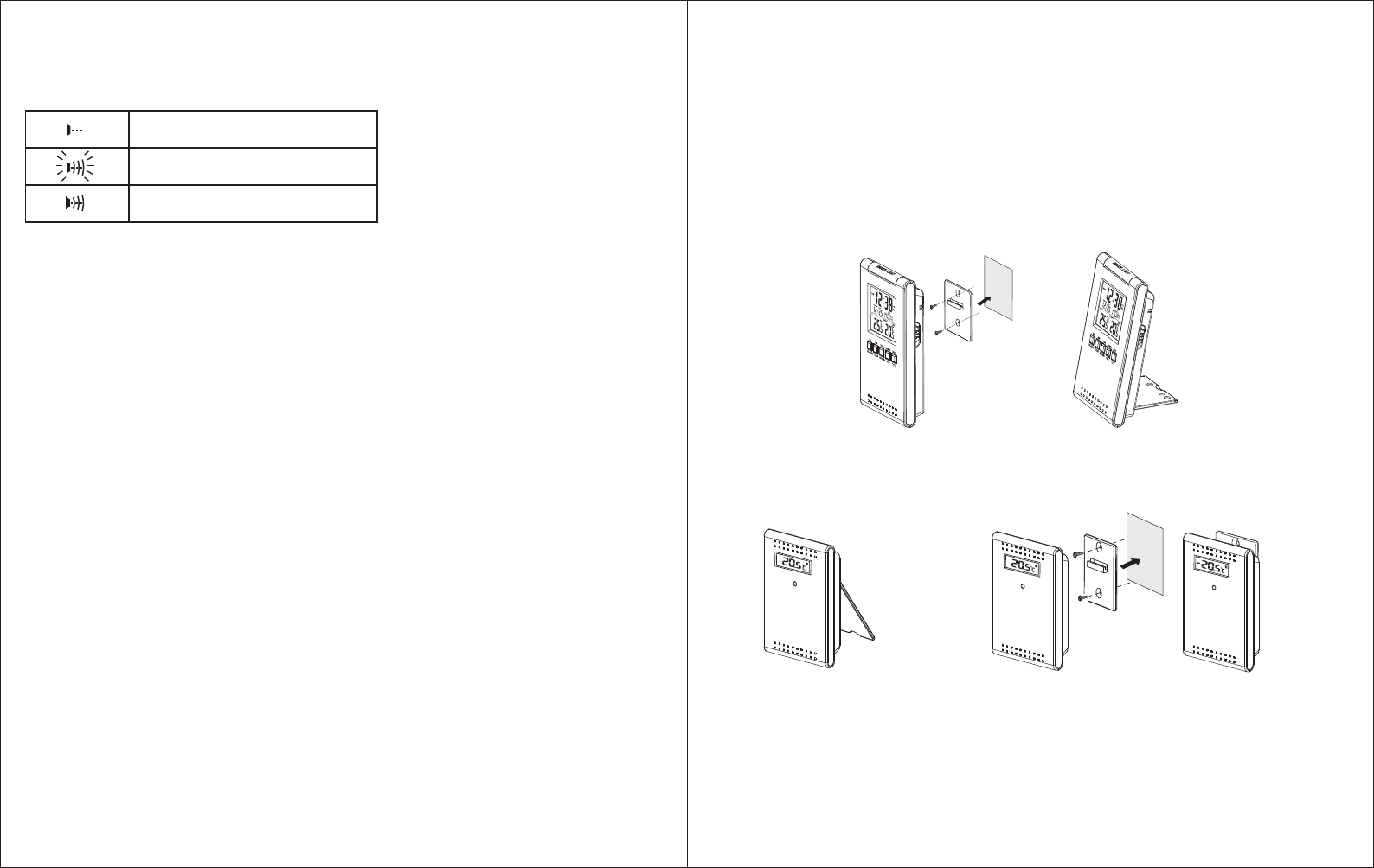
Using the Stand
The main unit equipped with a flip stand, you can use the stand to place the main unit on
flat surface, or flip the stand back and hang the main unit on wall with the wall mount holder.
The remote unit comes with a wall mount holder which can hold the unit on wall, or just place it on a flat
surface with the flip stand.
NO SIGNAL DETECTION
SIGNAL DETECTION
SUCCESSFUL RECEPTION
Perspective view from
front and right side Perspective view from
front and right side
Perspective view from
front and right side Perspective view from front and left side

M059M059
Warning: Changes or modifications to this unit not expressly approved by the party
responsible for compliance could void the user's authority to operate the equipment.
Note: This equipment has been tested and found to comply with the limits for a Class B
digital device, pursuant to Part 15 of the FCC Rules. These limits are designed to provide
reasonable protection against harmful interference in a residential installation. This
equipment generates, uses and can radiate radio frequency energy and, if not installed and
used in accordance with the instructions, may cause harmful interference to radio
communications.
However, there is no guarantee that interference will not occur in a particular installation. If
this equipment does cause harmful interference to radio or television reception, which can
be determined by turning the equipment off and on, the user is encouraged to try to correct
the interference by one of more of the following measures:
• Reorient or relocate the receiving antenna.
• Increase the separation between the equipment and receiver.
• Connect the equipment into an outlet on a circuit different from that to which the
receiver is connected.
• Consult the dealer or an experienced radio/TV technician for help.
Under the environment with radio frequency interference, the sample may malfunction and
require user to reset the sample.
Care of your clock
• Avoid exposing your clock to extreme temperatures, water or severe shock.
• Avoid contact with any corrosive materials such as perfume, alcohol or cleaning agents.
• Do not subject the clock to excessive force, shock, dust, temperature or humidity. Any of
these conditions may shorten the life of the clock.
• Do not tamper with any of the internal components of this clock. This will invalidate the
warranty and may cause damage.
Correct usage of the batteries
• Use 4 new "AA" batteries
• Do not mix standard of rechargeable batteries
• Do not mix new and old batteries
• When the low battery mark " " appears on the display, replace the appropriate
batteries with new ones.
Specification
Operation Temperature
Receiver : 0°C to 50°C
32°F to 122°F
Transmitter : -20°C to 60°C
-4°F to 140°F
Temperature measuring range
Receiver : -50°C to +70°C with 0.1°C resolution
-58°F to 158°F with 0.2°F resolution
Transmitter : -50°C to +70°C with 0.1°C resolution
-58°F to 158°F with 0.2°F resolution
Temperature checking interval
Receiver : every 16 seconds
Transmitter : every 16 seconds
Transmission distance: maximum 100 feet in open field, depending upon surrounding
structures, mounting location and possible interfering sources.
Power source ( Alkaline batteries recommended )
Receiver : 2 "AA" batteries, 1.5V batteries
Transmitter : 2 "AA" batteries, 1.5V batteries
Battery life : about 12 months
Dimension ( L x W x H )
Receiver : 70 x 20 x 119 mm
Transmitter : 70 x 22 x 100 mm
P.8P.7
M059