Electronics NL v.N1 Series and Access 800 TCNE Series User Manual
International Electronics Inc. v.N1 Series and Access 800 TCNE Series Users Manual
Users Manual
A7817A
1
Profile Series v.N1 Access Control Lock
Operating Manual
For assistance, contact SARGENT at 800-810-WIRE (9473) or visit www.sargentlock.com.

A7817A
2
Table Of Contents
TABLE OF CONTENTS .................................................................................................. 2
SECTION 1: INTRODUCTION........................................................................................ 3
1.1 PRODUCT DESCRIPTION ................................................................................................... 3
1.2 PRODUCT FEATURES........................................................................................................ 3
1.3 SPECIFICATIONS............................................................................................................... 4
1.4 LED FUNCTIONS.............................................................................................................. 5
SECTION 2: SYSTEM OPERATION............................................................................... 6
2.1 PRESENTING A PROXIMITY CARD / ENTERING A KEYPAD CODE ............................................ 6
2.2 OPERATING THE SOLENOID.................................................................................................... 7
2.3 CONTROLLING THE REQUEST TO EXIT, DOOR POSITION SWITCH, DEADBOLT MONITOR AND
LATCH BOLT MONITOR................................................................................................................ 7
SECTION 3: SYSTEM CONFIGURATION...................................................................... 8
3.1 SELECTING THE READER ADDRESS ........................................................................................ 8
3.2 CONFIGURING THE SOLENOID ................................................................................................ 9
3.3 ENABLING THE TAMPER SWITCH ........................................................................................... 9
3.4 CONFIGURING THE READER LED OPERATION ....................................................................... 9
3.5 DIP-SWITCH SETTING CHART .............................................................................................. 10
SECTION 4: WIRING.................................................................................................... 11
4.1 READER CONNECTOR DIAGRAM .......................................................................................... 11
4.2 INTERFACE MODULE CONNECTOR DIAGRAM....................................................................... 12
4.3 AUXILIARY (AUX) RELAY BOARD CONNECTOR DIAGRAM.................................................. 13
4.4 WIRING THE READER TO THE INTERFACE MODULE USING ONE POWER SUPPLY ................. 14
4.5 WIRING THE READER TO THE INTERFACE MODULE USING MULTIPLE POWER SUPPLIES ..... 15
4.6 WIRING A SOLENOID TO THE READER .................................................................................. 16
4.7 CONNECTING THE AUX RELAY BOARD TO THE INTERFACE MODULE .................................. 17
4.8 WIRING A DOOR POSITION SWITCH (DPS), REQUEST TO EXIT (RX) SWITCH, LATCH BOLT
(LX) AND DEADBOLT MONITOR (DX) SWITCH TO THE READER................................................ 18

A7817A
3
Section 1: Introduction
1.1 Product Description
The Profile Series v.N1 Access Control Lock is designed to integrate into an existing
Wiegand access control system.
The unit consists of three components: the Reader(s), the Interface Module and the
Auxiliary Relay Board. The Reader resides within the exterior escutcheon on each door
and connects to the prox antenna, the keypad and it wires back to the Interface Module.
The Interface Module connects the v.N1 system to the access control system and it
supports from one to four Readers.
The third component is the Auxiliary Relay Board. These relay outputs are controlled by
the Latch Bolt and Deadbolt switches in lock bodies. Refer to section 4.8 for further
details.
1.2 Product Features
• Supports 1 to 4 Doors
• Card Reader is 39-bit HID Compatible
• Keypad Data is Sent as 8-bit Burst
• RX (Request to Exit)
• Door Position Switch Monitor
• Deadbolt Monitor
• Latch Bolt Monitor
• Supports Fail-Safe and Fail-Secure Solenoid Locking Devices
NOTE:
This device complies with Part 15 of the FCC Rules. Operation is subject
to the following two conditions: (1) this device may not cause harmful
interference, and (2) this device must accept any interference received,
including interference that may cause undesired operation.
Changes or modifications not expressly approved by the party responsible
for compliance could void the user's authority to operate the equipment.
A7817A
4
1.3 Specifications
Electrical Specifications
Operating Voltage 12 to 30 VDC
Current Draw Reader: 36mA (Typical); 46mA (Max)
Interface Module: 59mA (Typical); 182mA (Max)*
Aux Relay Board: 17mA (Typical); 386mA (Max)*
*The max current draw on the Interface Module was calculated by
adding 18mA for each relay energized. The max current draw on
the Aux Relay Board was calculated by adding 21mA for each relay
and LED.
Relay Contacts 12-24VAC/DC; 1A (max)
Cable Specifications
RS-485 Cable (between
Reader and Interface
Module)
24 AWG, shielded two-twisted pair telephone cable with
a shunt capacitance of 16pF/Ft.
Maximum of 4000 Ft.
Power Supply Cable 18 AWG – 22 AWG (dependent on distance) stranded.
RX and Door Contact Cable 18 – 22 AWG (dependent on distance) stranded and
shielded.
Lock Input Cable 18 – 22 AWG (depended on distance) stranded.
Wiegand Data Cable (Data 0
and Data 1 18 – 22 AWG (dependent on distance) stranded and
shielded.
LED and Sounder Control
Cable 18 – 22 AWG (dependent on distance) stranded and
shielded.
Mechanical Specifications
Interface Module Dimensions 4” x 6”
Aux Relay Board Dimensions 4” x 6”
Miscellaneous Specifications
Operating Temperature -35°C to +66°C (-31°F to + 151°F)
Compatible Proximity Cards HID format cards up to 39 bits in length

A7817A
5
1.4 LED Functions
The following chart describes the function of the LED’s on the circuit boards.
Interface Module
LED Color Function Normal
Condition Error
Condition
LED1 Yellow Indicates a Reader is
offline Off Solid
LED2 Red Indicates communication
errors between a Reader
and Interface Module
Off Flashing
Rapidly
LED3 Green Indicates successful
communication between
the Readers and the
Interface Module
Flashing Rapidly Off
LED4 Green Indicates the 9V
regulator on the PCB is
functioning
On Off
LED5 Green Indicates the 5V
regulator on the PCB is
functioning
On Off
LED6 Green Indicates the tamper
relay is energized On Off
Reader
LED Color Function Normal
Condition Error
Condition
LED5 Red Indicates valid proximity
card read. Flash on valid
proximity card
read
N/A
LED6 Green Indicates valid proximity
card read. Flash on valid
proximity card
read
N/A
Auxiliary Relay Board
LED Color Function Normal
Condition Error
Condition
LED1-16 Green Indicates the Aux Relay
is Energized On = Relay
energized
Off = Relay de-
energized
N/A

A7817A
6
Section 2: System Operation
The following section discusses the overall operation of the Profile Series v.N1 Access
Control Lock. Section 3 covers how to configure the system to fit your application.
2.1 Presenting a Proximity Card / Entering a Keypad Code
As mentioned above, the Reader is the device used at the door to gain access.
Depending on the system, the user has the option to enter either keypad data, present a
proximity card or both. The Reader then transmits the keypad and/or card data back to
the Interface Module over the RS-485 wires. The data is processed by the Interface
Module and transmitted to the access control panel. The access control system then
makes the decision whether or not to allow access. If a prox card was presented to the
Reader, the Interface Module transmits the wiegand data directly to the panel. The
Reader can read HID format cards up to 39 bits in length. If a code is entered on the
keypad, the Interface Module sends each keypress individually to the access control
panel in an 8-bit burst. The chart below shows the data for each keypress.
Key Binary Data Hex Data
1 11100001 E1
2 11010010 D2
3 11000011 C3
4 10110100 B4
5 10100101 A5
6 10010110 96
7 10000111 87
8 01111000 78
9 01101001 69
0 11110000 F0
* 01011010 5A
# 01001011 4B
The keypad and card data is transmitted from the Data 0 and Data 1 terminals on the
Interface Module.

A7817A
7
2.2 Operating the Solenoid
The Reader operates a solenoid locking device. Once the access control system
validates the users keypad or card data, the door can now be unlocked. Shorting the
two lock terminals on the Interface Module together activates the locking device.
Connect these terminals to a normally open dry contact on the access control panel
used to control the door. When the short is removed the locking device returns to the
locked condition. The solenoid configuration is discussed in section 3.2.
2.3 Controlling the Request to Exit, Door Position Switch,
Deadbolt Monitor and Latch Bolt Monitor
The Reader is equipped with a Request to Exit (RX) input, a Door Position Switch
(DPS) input, a Deadbolt (DX) Monitor and a Latch Bolt (LX) Monitor. These are located
on connector J3. On this connector there is a Loop Common connection (pin 1). To
operate these inputs just short the desired input to the Loop Common wire. When the
RX or DSP inputs are closed, the corresponding relay on the Interface Module is
energized. When the LX input is closed the Aux 1 relay on the Aux Relay Board is
energized and when the DX is closed the Aux 2 relay is energized. See section 4.8 for
further details.
A7817A
8
Section 3: System Configuration
This section explains how to configure your Profile Series vN.1 Access Control Lock
system. Each sub-section describes the various configuration options. At the end
section 3 there is a chart that shows all the dip-switch settings for quick reference.
3.1 Selecting the Reader Address
One Interface Module can support from one to four Readers. You must assign each
Reader an address before you connect it to the Interface Module. Each Reader must
have a different address assigned to it. This enables the Interface Module to distinguish
each Reader from one another. The Reader address is selected by configuring dip-
switches 1 and 2 on switch SW2 on the rear of the Reader board. The chart below
shows these switch settings.
Reader Address Switch 1 Switch 2
Reader #1 Open Open
Reader #2 Closed Open
Reader #3 Open Closed
Reader #4 Closed Closed
Once you’ve assigned the Reader addresses you now must configure the Interface
Module to communicate with them. This is done by selecting which Readers are
connected using dip-switches 1 through 4 on switch S2 on the Interface Module. To
select a Reader close the corresponding switch and if a Reader is not connected leave
the switch open. The chart below shows these switch settings.
Switch Function Open Closed
1 Reader 1 Select Reader 1 Not Connected Reader 1 Connected
2 Reader 2 Select Reader 2 Not Connected Reader 2 Connected
3 Reader 3 Select Reader 3 Not Connected Reader 3 Connected
4 Reader 4 Select Reader 4 Not Connected Reader 4 Connected

A7817A
9
3.2 Configuring the Solenoid
The solenoid can operate in either fail-safe or fail-secure mode. Fail-safe means the
solenoid is energized in the locked position and is then de-energized when unlocked.
This also means when power is lost the solenoid is de-energized and the door is
unlocked. Fail-secure is the opposite, meaning the solenoid is de-energized in the
locked position and is then energized when unlocked. When power is lost the solenoid
remains de-energized and the door is locked. This is selected with dip-switch 5 on
switch S1 on the Reader. When this switch is open the unit is in fail-safe mode and
when the switch is closed it’s in fail-secure mode. Refer to the table in section 3.6 for
the dip switch setting.
3.3 Enabling the Tamper Switch
Each Reader has a magnetic Hall Effect switch, which is used as a tamper switch. To
enable the tamper switch close dip-switch 7 on switch S1 on the Reader. Each interior
escutcheon is equipped with a magnet. When the magnet is in place, the tamper relay
on the Interface Module is energized and LED6 is on. This is the normal condition,
indicating the door is secure. When the magnet is removed the tamper relay de-
energizes and LED6 turns off. This indicates the unit was tampered with.
When more than one Reader, with the tamper switch enabled, is connected, the
magnets must be in place on each Reader for it to operate properly. When a magnet is
removed from any one of the Readers, the tamper relay de-energizes.
There is an additional tamper option, which is used to indicate if a door goes offline (due
to a malfunction or was disconnected from the Interface Module). To enable this option
close dip-switch 4 on switch S1 on the Interface Module. Now, if a Reader goes offline,
the tamper relay de-energizes. Please note that the tamper switch does not need to be
enabled on the Reader for this feature to work.
3.4 Configuring the Reader LED Operation
The Reader has a red/green bi-color LED on the on the front of the keypad. The red
LED operation is controlled by dip-switch 6 on switch S1 on the Reader. When this
switch is open the red LED is off. If you close dip-switch 6, the red LED turns on.
You can use the bi-color LED to indicate the status of your control panel by changing
the LED to green when the door is unlocked. The LED control terminal on the Interface
Module is used to control the status of the LED on the Reader. Dip-switch 3 on S1 on
the Interface Module selects how the LED control terminal operates. When this switch
is open the LED turns green when the terminal is pulled low (ground). When this switch
is closed the LED turns green when the terminal is pulled high (positive voltage).

A7817A
10
3.5 Dip-Switch Setting Chart
The charts below show all the dip-switch settings on the Interface Module and the
Reader. If a switch is not used, leave it open.
Reader Switch S1
Dip-Switch Function Open Closed
1 Not Used N/A N/A
2 Not Used N/A N/A
3 Not Used N/A N/A
4 Solenoid Select N/A Solenoid
5 Fail Safe/Fail Secure
Select Fail Safe Fail Secure
6 Red LED Select Red LED Off Red LED On
7 Tamper Input Select Tamper Disabled Tamper Enabled
8 Not Used N/A N/A
Reader Switch SW2
Dip-Switch Function Open Closed
1 Reader Address
Select See section 3.1
2 Reader Address
Select See section 3.1
3 Not Used N/A N/A
4 Not Used N/A N/A
Interface Module Switch S1
Dip-Switch Function Open Closed
1 Not Used N/A N/A
2 Not Used N/A N/A
3 Green LED
Operation Pull Led control terminal
low to operate Pull Led control
terminal high to
operate
4 Tamper Operation Tamper only activates
when magnet removed Tamper activates if
any door goes offline
Interface Module Switch S2
Dip-Switch Function Open Closed
1 Reader 1 Select Reader 1 Not Connected Reader 1 Connected
2 Reader 2 Select Reader 2 Not Connected Reader 2 Connected
3 Reader 3 Select Reader 3 Not Connected Reader 3 Connected
4 Reader 4 Select Reader 4 Not Connected Reader 4 Connected
5 Not Used N/A N/A
6 Not Used N/A N/A
7 Not Used N/A N/A
8 Not Used N/A N/A
A7817A
11
Section 4: Wiring
The following section contains diagrams and descriptions detailing how to wire the
Profile Series v.N1 Access Control Lock.
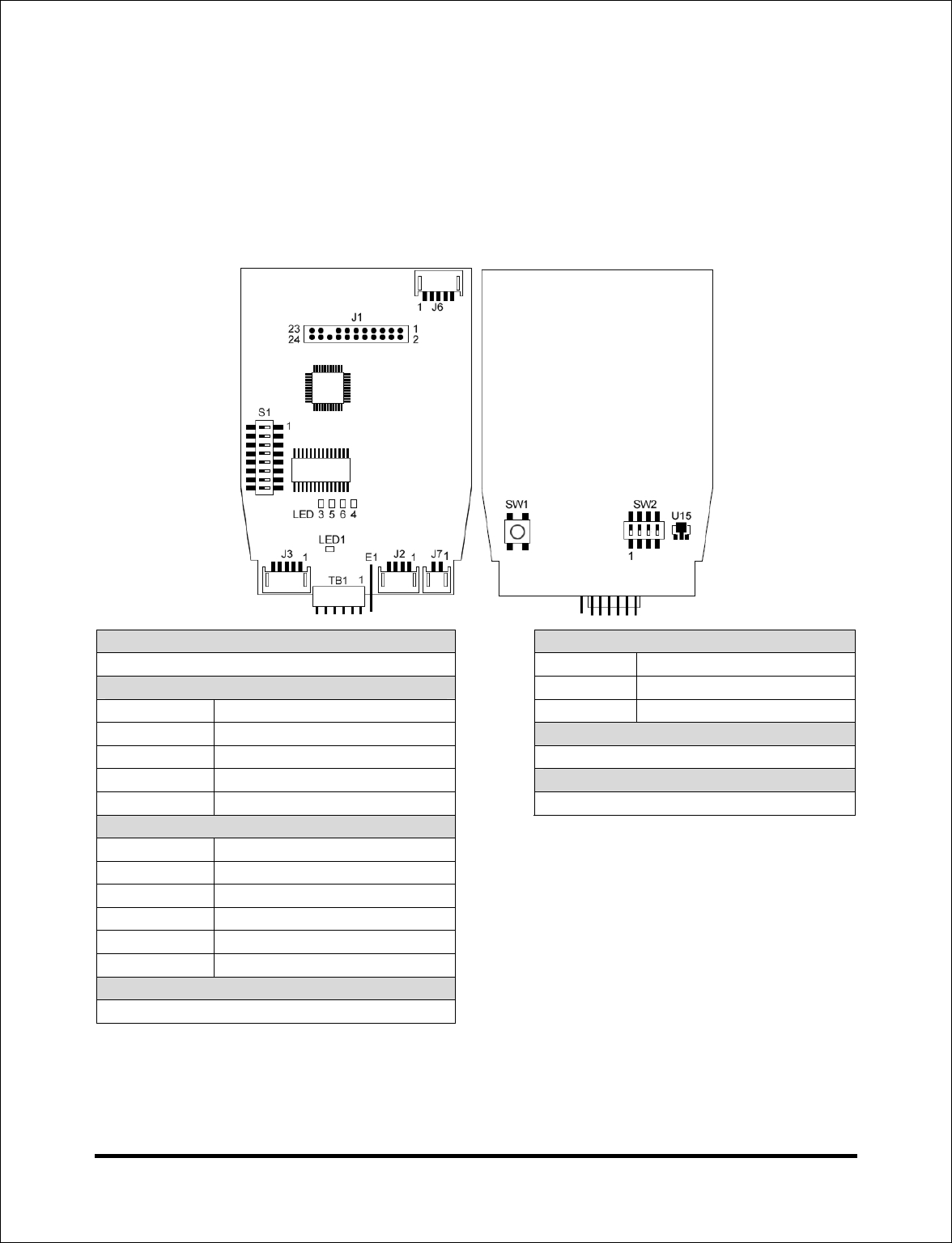
4.1 Reader Connector Diagram
Connector J1 Connector J7
Keypad Ribbon Cable Connector Position Connection
Connector J2 1 Solenoid Positive
Position Connection 2 Solenoid Negative
1 RS-485 Data B Connector TB1
2 RS-485 Data A Not Used
3 Reader +12-30VDC Connector E1
4 Reader Ground Earth Ground Connection
Connector J3
Position Connection
1 Loop Common
2 RX Input
3 Door Switch Monitor
4 Latch Bolt Input
5 Deadbolt Input
Connector J6
Not Used
A7817A
12
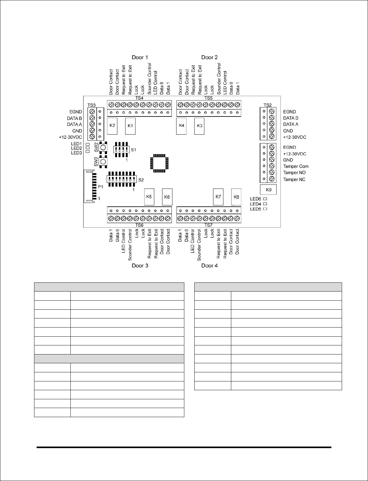
4.2 Interface Module Connector Diagram
Terminal Strip TS1 Terminal Strips TS4, TS5, TS6 and TS7
Position Connection Position Connection
1 Power Supply Earth Ground 1 Door Switch Normally Open
2 Power Supply +12-30 VDC 2 Door Switch Common
3 Power Supply Ground 3 Request to Exit Normally Open
4 Tamper Relay Common 4 Request to Exit Common
5 Tamper Relay Normally Open 5 Lock Input
6 Tamper Relay Normally Closed 6 Lock Input
Terminal Strips TS2 and TS3 7 Sounder Control
Position Connection 8 LED Control
1 Reader +12-30 VDC 9 Data 0
2 Reader Ground 10 Data 1
3 RS-485 Data A
4 RS-485 Data B
5 Reader Earth Ground
A7817A
13
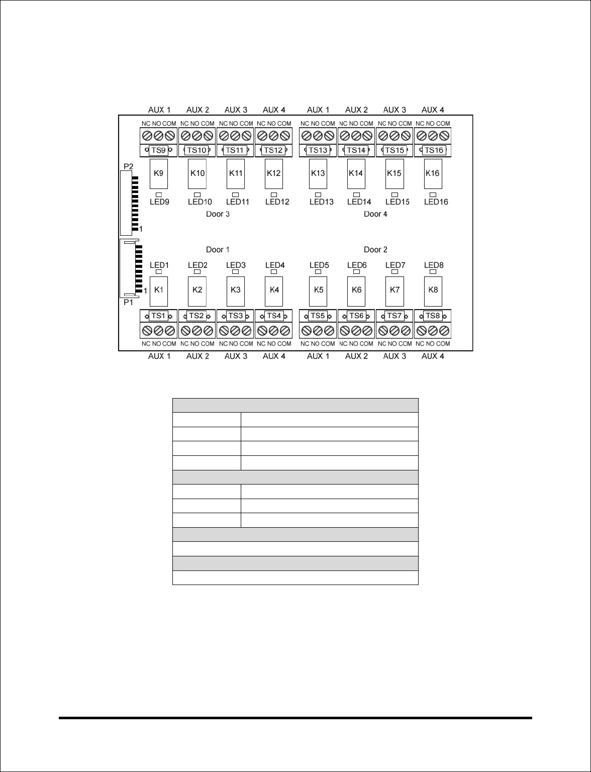
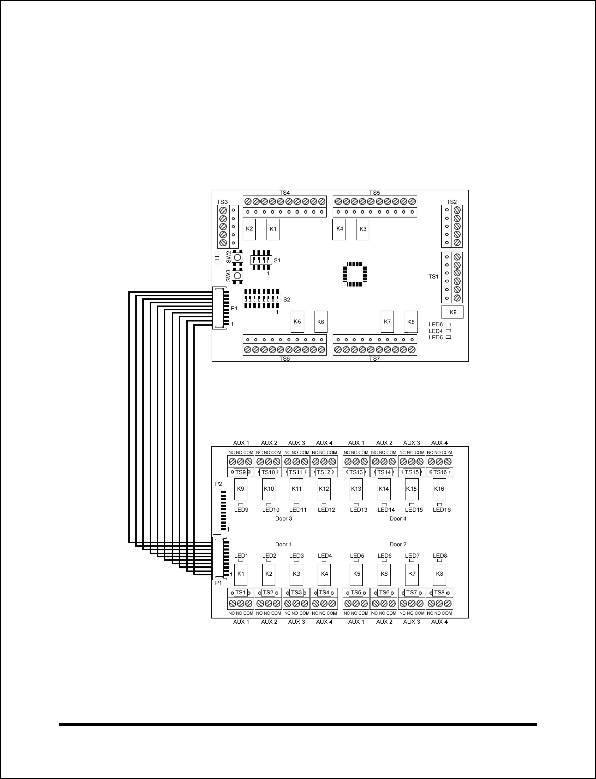
4.3 Auxiliary (Aux) Relay Board Connector Diagram
Terminal Strips 1 through16
TS1-4 Reader 1 Aux Outputs
TS5-8 Reader 2 Aux Outputs
TS9-12 Reader 3 Aux Outputs
TS13-16 Reader 4 Aux Outputs
Terminal Strip Connections
NC Relay Normally Closed
NO Relay Normally Open
COM Relay Common
Connector P1
Interface Module Connector
Connector P2
Not Used
A7817A
14
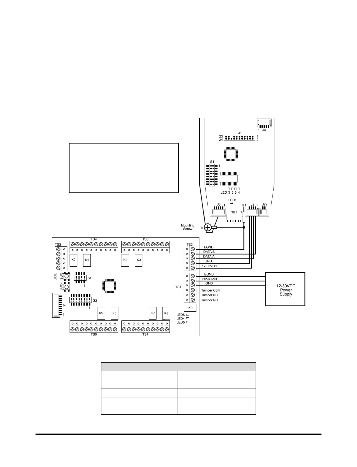
4.4 Wiring the Reader to the Interface Module Using One
Power Supply
The Diagram below shows how to wire the Reader to the Interface Module using a
single power supply. If you are connecting multiple Readers (up to 4), wire them in
parallel using terminal strips TS2 and TS3, following the diagram below. The chart also
shows these connections. Connect the power supply to TS1 as shown.
Reader Interface Module
J2: Pin 1 TS2/TS3: Data B
J2: Pin 2 TS2/TS3: Data A
J2: Pin 3 TS2/TS3: +12-30VDC
J2: Pin 4 TS2/TS3: GND
E1 Earth Ground Tab TS2/TS3: EGND
Note: The earth ground tab E1
on each Reader must be
connected to the mounting
screw in the rear housing as
shown in the diagram.
A7817A
15
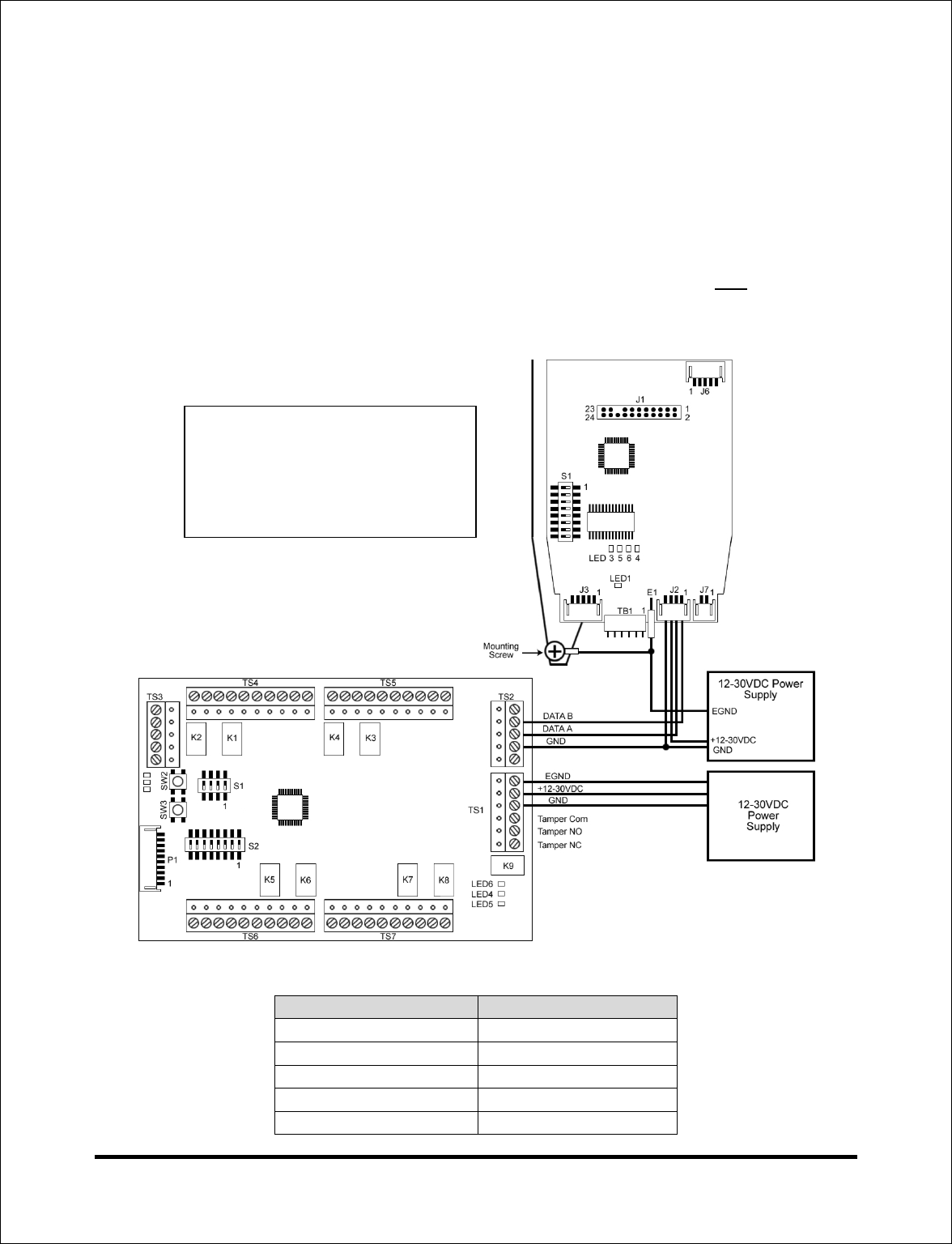
4.5 Wiring the Reader to the Interface Module Using Multiple
Power Supplies
The Diagram below shows how to wire the Reader to the Interface Module using more
than one power supply. When you are using multiple power supplies do not connect the
Reader +12-30VDC (J2, pin 3) or earth ground (E1) to the Interface Module. Wire the
Reader +12-30VDC and earth ground connections to the additional power supply. The
Reader ground wires must be connected to the additional power supply and the
Interface Module ground, however. You can use an additional power supply for each
Reader you have connected by following the diagram below.
Reader Interface Module
J2: Pin 1 TS2/TS3: Data B
J2: Pin 2 TS2/TS3: Data A
J2: Pin 3 Not Connected
J2: Pin 4 TS2/TS3: GND
E1 Earth Ground Tab TS2/TS3: EGND
Note: The earth ground tab E1
on each Reader must be
connected to the mounting
screw in the rear housing as
shown in the diagram.
A7817A
16
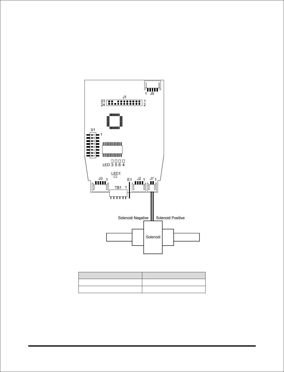
4.6 Wiring a solenoid to the Reader
The diagram below shows how to connect a solenoid to the Reader. The solenoid is
connected to connector J7 as shown.
Reader Connector J7 Solenoid Connection
Pin 1 Solenoid Positive
Pin 2 Solenoid Negative
A7817A
17
4.7 Connecting the Aux Relay Board to the Interface Module
The Aux Relay Board is connected to the Interface Module with a 10-position wire
harness. This wire harness is plugged into P1 on both boards, as shown in the diagram
below.
A7817A
18
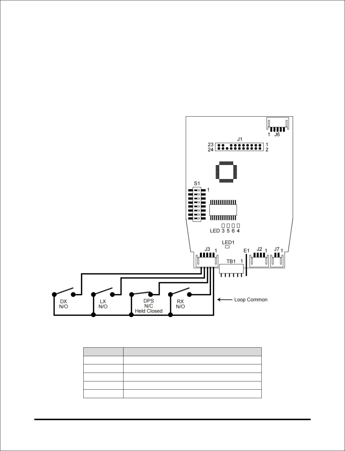
4.8 Wiring a Door Position Switch (DPS), Request to Exit (RX)
switch, Latch Bolt (LX) and Deadbolt Monitor (DX) switch to
the Reader
The diagram below shows how to connect a normally open Request to Exit device and
a normally closed latch held closed door position switch. When the RX device is closed,
the RX relay on the Interface Module energizes. When the door position switch is
opened, the door contact relay on the Interface Module de-energizes.
Reader J3 Connection
Pin 1 Loop Common
Pin 2 RX/Normally Open
Pin 3 Door Switch/Normally Closed/Held Closed
Pin 4 Latch Bolt/Normally Open
Pin 5 Deadbolt/Normally Open

Document #: 6055100, Rev 1.0, D1f
Page left blank intentionally

Document #: 6055100, Rev 1.0, D1f