Elettronika S r l TXUP1000 1000 Watt Analog TV Broadcast Transmitter User Manual APT139B VEGA Rev0 Date100604
Elettronika S.r.l. 1000 Watt Analog TV Broadcast Transmitter APT139B VEGA Rev0 Date100604
UserManual.wiki
>
Elettronika S r l
>
TXUP1000 User Manual
>
Exciter User Manual Part 1
Contents
1.
Exciter User Manual Part 1
2.
Exciter User Manual Part 2
3.
Exciter User Manual Part 3
4.
Amplifier User manual Part 1
5.
Amplifier User Manual Part 2
Exciter User Manual Part 1
Navigation menu
Upload a User Manual
Namespaces
Wiki Guide
HTML
PDF
Info
Views
User Manual
Discussion / Help
Navigation


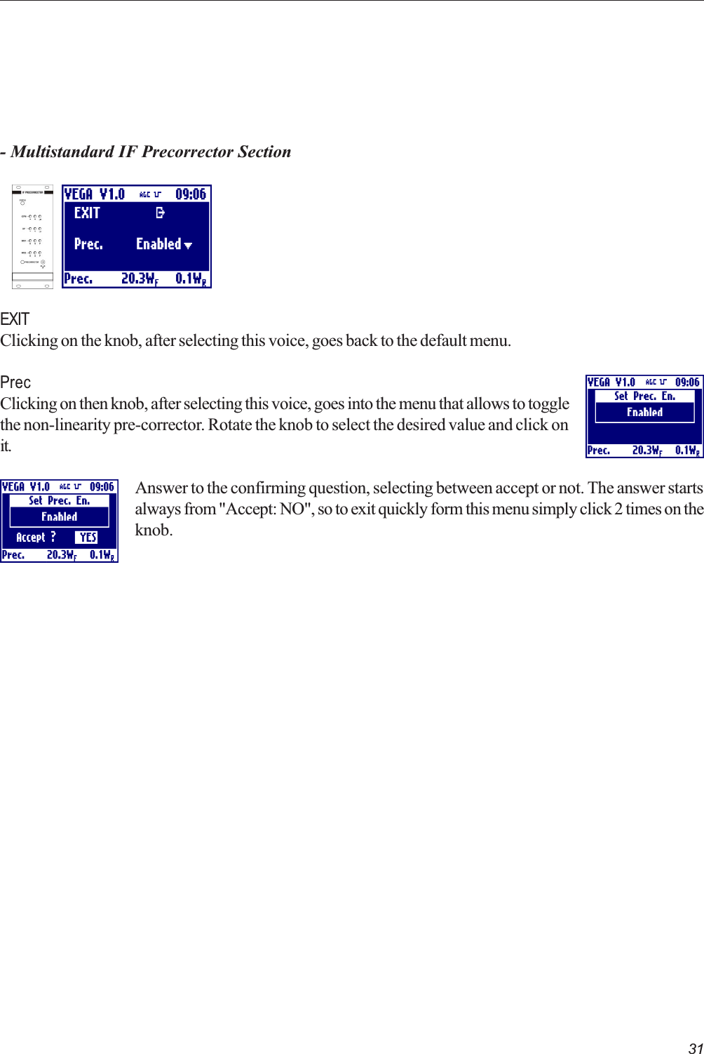
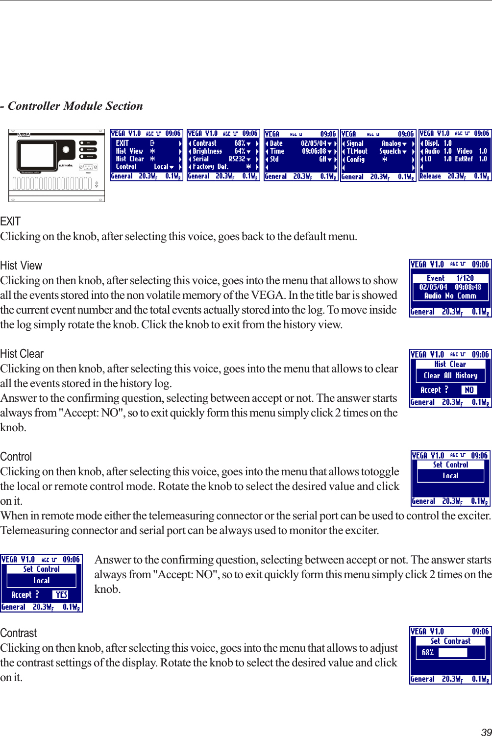
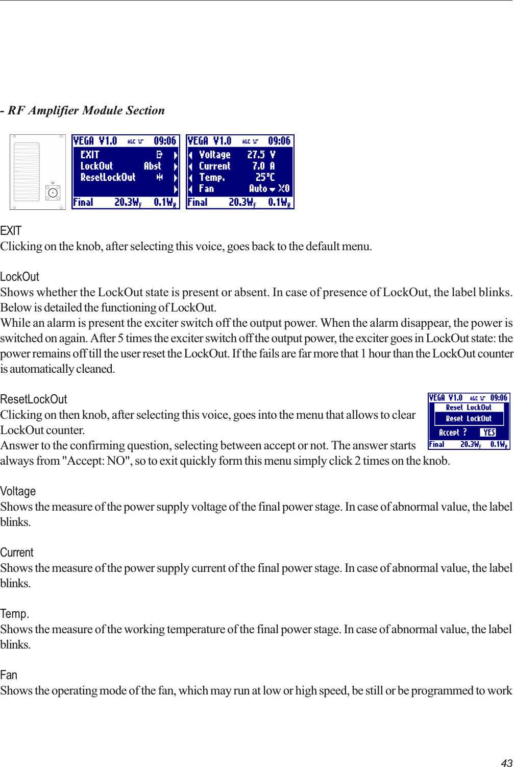
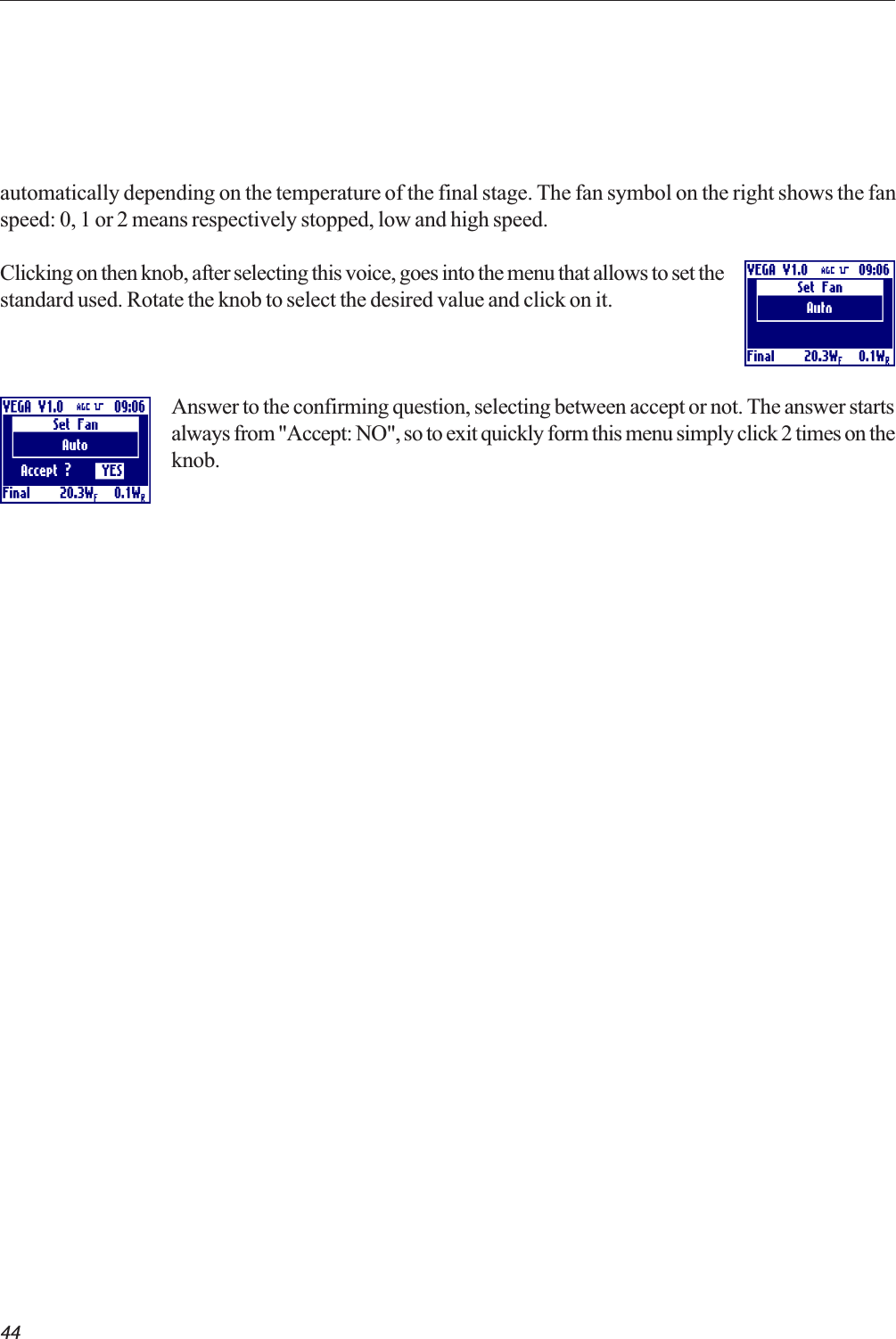
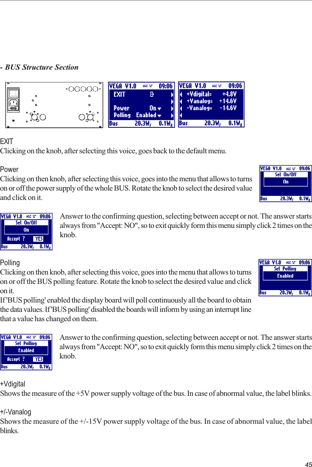
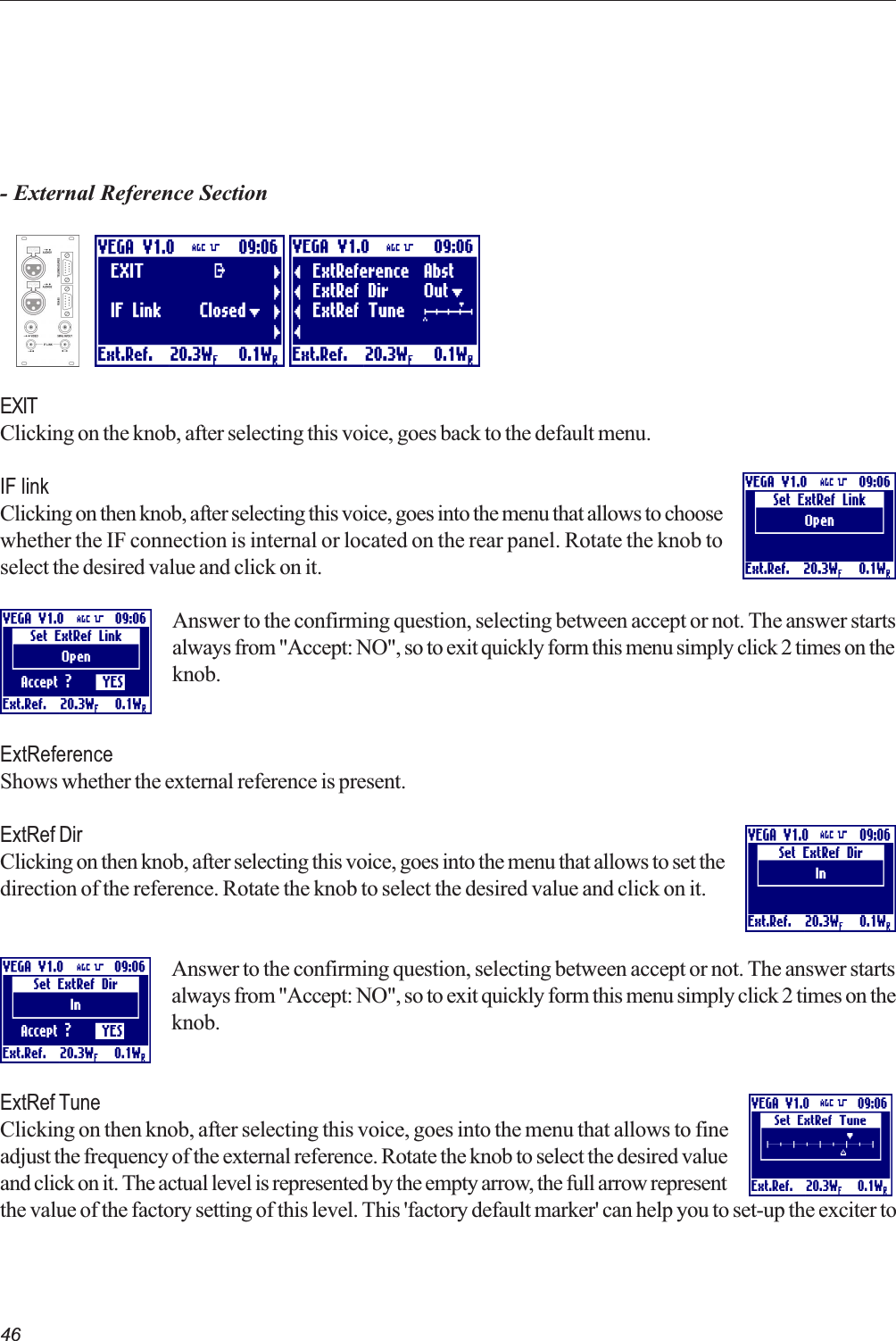
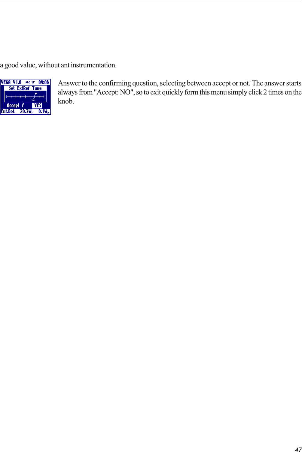
![32- Multistandard Local Oscillator Section with Line OffsetEXITClicking on the knob, after selecting this voice, goes back to the default menu.ChannelClicking on then knob, after selecting this voice, goes into the menu that allows to selectthe transmission channel for the selected standard. Rotate the knob to select the desiredvalue and click on it.Answer to the confirming question, selecting between accept or not. The answer startsalways from "Accept: NO", so to exit quickly form this menu simply click 2 times on theknob.Line offsetClicking on then knob, after selecting this voice, goes into the menu that allows to set theline offset in either positive (P) or negative(M) steps from 15M to 15P. Rotate the knobto select the desired value and click on it.Offset[Hz] = LineOffset[Step]*(LineFrequency[Hz]/12)Answer to the confirming question, selecting between accept or not. The answer startsalways from "Accept: NO", so to exit quickly form this menu simply click 2 times on theknob.VCOShows the oscillator PLL lock or unlock. In case of unlock, the label blinks.](https://usermanual.wiki/Elettronika-S-r-l/TXUP1000.Exciter-User-Manual-Part-1/User-Guide-636780-Page-32.png)
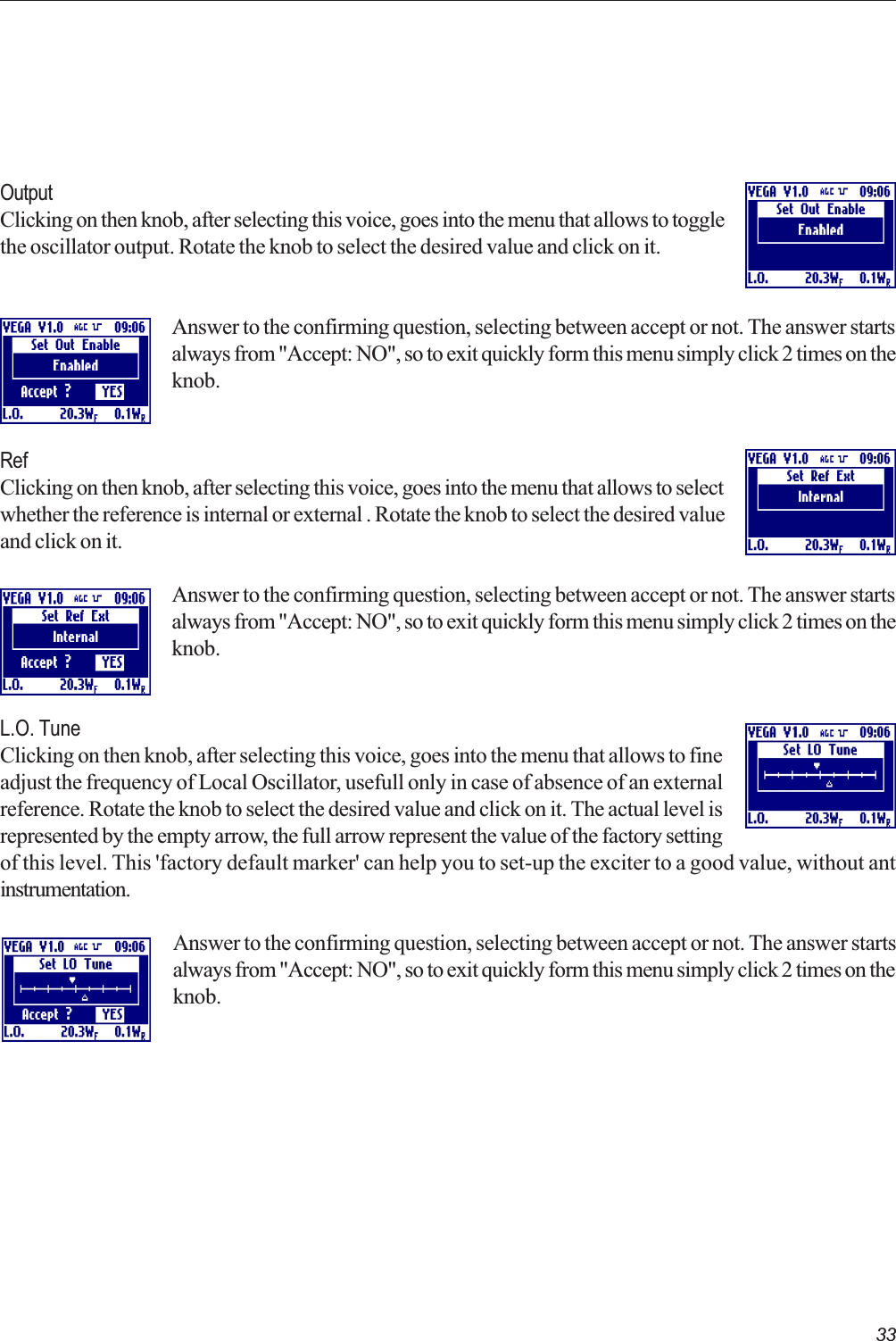
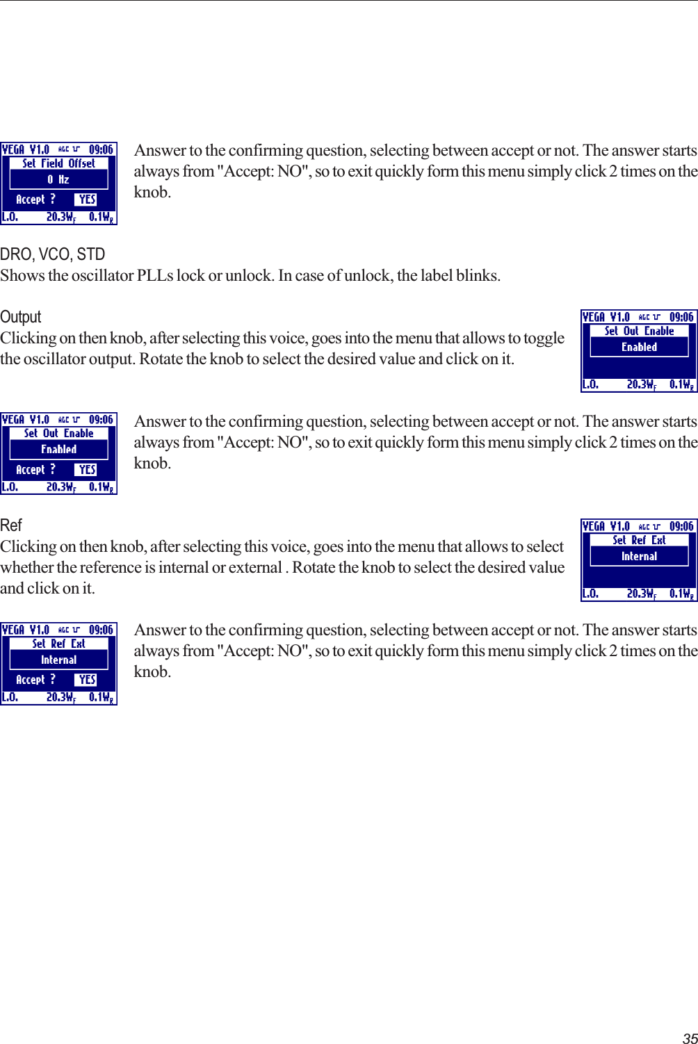
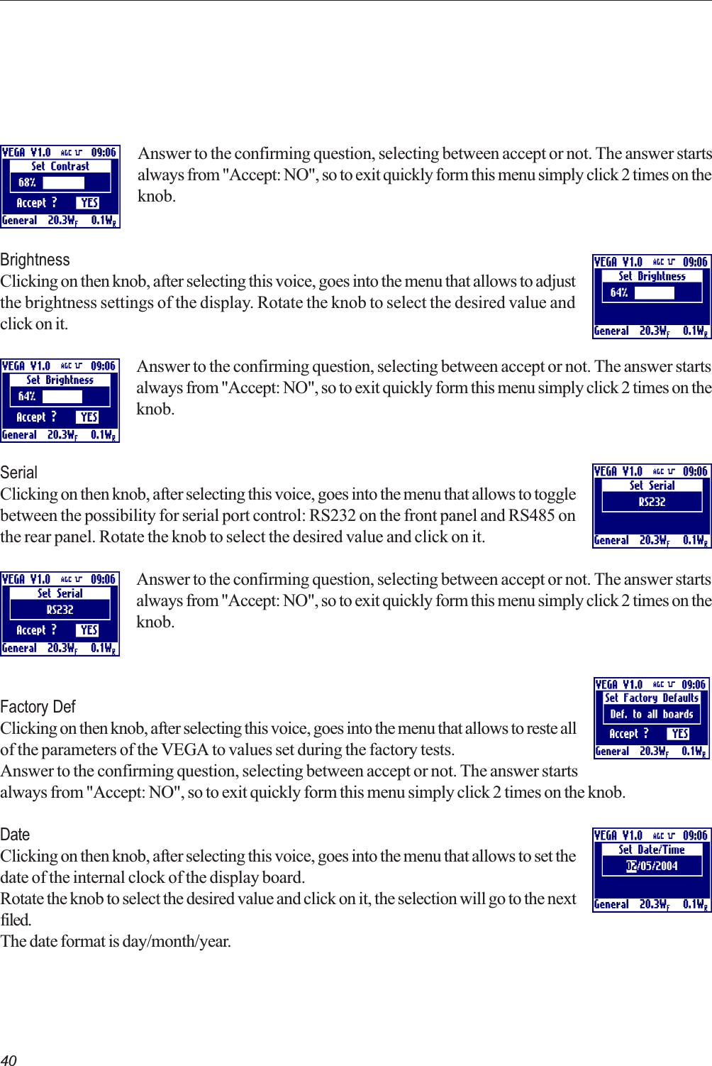
![34- Multistandard Local Oscillator Section with Field Offset (Option)EXITClicking on the knob, after selecting this voice, goes back to the default menu.ChannelClicking on then knob, after selecting this voice, goes into the menu that allows to selectthe transmission channel for the selected standard. Rotate the knob to select the desiredvalue and click on it.Answer to the confirming question, selecting between accept or not. The answer startsalways from "Accept: NO", so to exit quickly form this menu simply click 2 times on theknob.Line offsetClicking on then knob, after selecting this voice, goes into the menu that allows to set theline offset in either positive (P) or negative(M) steps from 15M to 15P. Rotate the knobto select the desired value and click on it.Answer to the confirming question, selecting between accept or not. The answer startsalways from "Accept: NO", so to exit quickly form this menu simply click 2 times on theknob.Field offsetClicking on then knob, after selecting this voice, goes into the menu that allows to set thefiled offset in Hertz from -700Hz to +700Hz. This is added to the line offset. Rotate theknob to select the desired value and click on it.TotalOffset[Hz] = FieldOffset[Hz]+LineOffset[Step]*(LineFrequency[Hz]/12)](https://usermanual.wiki/Elettronika-S-r-l/TXUP1000.Exciter-User-Manual-Part-1/User-Guide-636780-Page-34.png)