Elettronika S r l TXUP2000 2 kW Analog TV Broadcast transmitter User Manual APT088A AUTV 2000LD Rev0 Date170203 p65
Elettronika S.r.l. 2 kW Analog TV Broadcast transmitter APT088A AUTV 2000LD Rev0 Date170203 p65
Contents
- 1. User Manual Part 1
- 2. User Manual Part 2
User Manual Part 1

AUTV/2000LD
LDMOS - UHF TV Amplifier
Users manual
CODE: APT088A TITLE: AUTV/2000LD REV: 0 DATE: 17/02/03

SS 96 Km 113
70027 Palo del Colle (Ba) ITALY
Tel. +39 (0)80 626755
Fax +39 (0)80 629262
E-mail: elettronika@elettronika.it
Web siste: http://www.elettronika.it
Registration number: IT-17686
Registration number: IT-24436

Index
Index ................................................................................................................................... 3
Warning .............................................................................................................................. 5
Warranty ............................................................................................................................. 6
Introduction ....................................................................................................................... 7
Content of the manual....................................................................................................... 7
Treatment of electrical shock ........................................................................................... 9
First-aid ......................................................................................................................... 10
Treatment of electrical burns.......................................................................................... 10
Note ............................................................................................................................... 10
APT088A AUTV/2000LD .................................................................................................. 11
Description .................................................................................................................... 12
Technical characteristics ............................................................................................... 13
APT088A AUTV/2000LD - Component list ....................................................................... 15
APG012B AMPLIFIER CONTROL ................................................................................... 17
1.1 Functions ................................................................................................................. 18
1.2 Programming mode ................................................................................................. 20
1.3 Setting...................................................................................................................... 20
- FWD Power calibration ............................................................................................. 20
- REF Power calibration.............................................................................................. 21
- UNB Calibration .......................................................................................................21
1.4 Remote control ........................................................................................................ 21
1.5 RS232 and RS485 Pin tables .................................................................................. 22
1.6 Telemeasuring pins table ........................................................................................ 23
1.7 Other tables.............................................................................................................. 24
Front panel .................................................................................................................... 26
Rear panel ..................................................................................................................... 27
APG012B AMPLIFIER CONTROL - Component list ...................................................... 29
SCH0109BR0 (Master board) ....................................................................................... 31
SCH0110BR0 (Analog input for master board).............................................................. 39
SCH0152AR0 (230VAC Switching board) ..................................................................... 42
SCH0153AR0 (In/Out digital for APG012B)................................................................... 45
S-50-24 (Switching power supply) .................................................................................. 48
APT084ASF AUTV/1000LD ............................................................................................. 53
Section 1 - Information .................................................................................................... 55
1.1 Description............................................................................................................... 56

1.2 Technical characteristics.......................................................................................... 57
Section 2 - Installation ..................................................................................................... 59
2.1 Operating environment ............................................................................................ 60
2.2 Preliminary operations............................................................................................. 60
2.3 Telemeasuring socket connections ......................................................................... 61
2.4 RS232 and RS485 socket connections ................................................................... 61
2.5 SCH0005AR1 Calibration procedure ...................................................................... 62
- Power supply voltages and currents calibration........................................................ 62
- Temperature calibration ........................................................................................... 63
- Forward power calibration ......................................................................................... 63
- Reflected power calibration ...................................................................................... 63
2.6 Preventive maintenance .......................................................................................... 64
Front panel .................................................................................................................... 65
Rear panel ..................................................................................................................... 66
Section 3 - Diagram ......................................................................................................... 67
Cable diagrams ............................................................................................................. 68
APT084ASF AUTV/1000LD - Component list .................................................................. 71
SCH0005AR1 (Protection board) .................................................................................. 73
SCH0004AR0 (Relay board) ......................................................................................... 82
PN502 (Display board) .................................................................................................. 87
MTF0050AR0 (1kW LDMOS Power module) ................................................................ 90
SP500-27/48 (Switching power supply) .......................................................................... 94
06641 (UHF Band-pass filter) ...................................................................................... 102

5
WARNING
The apparatus described in this manual has been designed and manufactured with devices to safe-
guard the users. In any case it is recommended that during any operation of installation, maintenance,
miscellaneous interventions and calibrations requiring the apparatus to be switched on,
THE USER TAKES ALL THE
PRECAUTIONS AGAINST INCIDENTS
It is required to use the proper clothes and protection gloves in order to prevent damages from inci-
dental contacts with high-voltage parts.
The manufacturer declines every responsibility in case the recommendations above are not followed.
IMPORTANT
The component lists attached to the relevant electrical diagrams indicate for each item the reference,
the description and the type normally used.
The Elettronika S.r.l. though reserves the right to use or supply as spare parts components with
equivalent characteristics but of a different type, assuring anyway the optimal work of the apparatus
in accordance with the specifications.
The enclosed monographs are solely owned by Elettronika S.r.l.
The use of anything enclosed in this technical manual without explicit authorization given by Elettronika
S.r.l. will be prosecuted by the law.
The data and technical characteristics of the apparatus described in this manual are not compelling for
the manufacturer.
The Elettronika S.r.l. reserves the right to make, without previous notice, modifications or updates in
order to improve the quality of the product.
The general conditions of supply and sale are described in the contracts.
The delivery time are in accordance with the products and quantities ordered.

6
Summary of warranty
We, ELETTRONIKA S.r.l., SS096 Km 113 Z.I. PALO DEL COLLE (BA) ITALY, warrant to the ORIGINAL PURCHASER of a NEW product, for a
period of one (1) year from the date of purchase by the original purchaser (the “warranty period”) that the new ELETTRONIKA product is free of defects
in materials and workmanship and will meet or exceed all advertised specifications for such a product. This warranty does not extend to any subsequent
purchaser or user, and automatically terminates upon sale or other disposition of our product.
Items excluded from this ELETTRONIKA warranty
We are not responsible for product failure caused by misuse, accident, or neglect. This warranty does not extend to any product on which the serial
number has been defaced, altered, or removed. It does not cover damage to loads or any other products or accessories resulting from ELETTRONIKA
product failure. It does not cover defects or damage caused by use of unauthorized modificstions, accessories, parts, or service.
What we will do
We will remedy any defect, in material or workmanship (except as excluded), in our sole discretion, by repair, replacement, or refund. If a refund is
elected, then you must make the defective or malfunctioning component available to us free and clear of all liens or other encumbrances. The refund will
be equal to the actual purchase price, not including interest, insurance, closing costs, and other finance charges less a reasonable depreciation on the
product from the date of original purchase. Warranty work can only be performed at our authorized service centers or at our factory. Expenses in
remedying the defect will be borne by ELETTRONIKA, including one-way surface freight shipping costs within the United States. (Purchaser must bear
the expense of shipping the product between any foreign country and the port of entry in the United States and all taxes, duties, and other custom’s fee(s)
for such foreign shipments).
How to obtain warranty service
You must notify us of your need for warranty service not later than ninety (90) days after the expiration of the warranty period. We will give you an
authorization to return the product for service. All components must be shipped in a factory pack or equivalent which, if needed, may
Desclaimer of consequential and incidental damages
You are not entitled to recover from us any consequential or incidental damages resulting from any defect in our product. This includes any damage
to another product or products resulting from such a defect.
Warranty alterations
No person has the authority to enlarge, or modify this warranty. The warranty is not extended by the lenght of time for which you are deprived of
the use of the product. Repairs and replacement parts are provided under the terms of this warranty shall carry only the unexpired portion of this
warranty.
Design changes
We reserve the right to change the design of any product from time to time without notice and with no obligation to make corresponding changes in
products previously manufactured.
Legal remedies of purchaser
There is no warranty which extends beyond the terms hereof. This written warranty is given in lieu of any oral or implied warranties not contained
herein. We disclaim all implied warranties, including without limitation any warranties of merchantability or fitness for a particular purpose. No action
to enforce this warranty shall be commenced later than ninety (90) days after expiration of the warranty period.
Warranty for electronic tubes
The warranty applied for electronic tubes is the one given by the manufacturer of the tube. In the event that the product shows anomalies within the
deadline of the validity of the warranty given by the manufacturer of the product itself, the buyer will have to return it to the seller with the needed
documents and the written description of the defect. The seller will ship the broken tube to the manufacturer in order to effect the necessary technical
tests to find out the cause of the anomaly. Meanwhile the buyer of the tube who needs to use, and as such to replace immediately the product, will have
to buy a new one and provide to the relevant payment, further to the issuing by the seller of a regular commercial invoice. After the adequate tests made
by the manufacturer, should the result be positive, that is confirm the defect in manufacturing, the seller will issue a regular credit note in the name of
the buyer and return the amount paid. Should the result be negative, that is detect a negligence in the installation or use by the buyer, he will have no
right against the seller.
Warranty

7
INTRODUCTION
The apparatus described in this manual is the latest of this series, offering high performances, remark-
able reliability and a wide range of characteristics, it all at a low cost.
Its is easy to install and use. It only takes to follow the installation procedure as shown in this manual:
after having removed all from the package, you only have to follow step by step the description in the
various sections.
Before starting to use the apparatus, remember to:
read carefully the general safety information contained in this section;
follow the instructions for the installation and set up of the apparatus;
read all the remaining sections of this manual in order to know well the apparatus and learn
how to obtain the best of its characteristics.
CONTENTS OF THE MANUAL
The chapter composing this manual contain all the information concerning the use of the apparatus.
For more information refer to ELETTRONIKA S.r.l.
This manual is made up of different chapters, each made up of various sections. Each individual
chapter represents a single apparatus composing the whole station.

8
WARNING!
The currents and voltages in this equipment are dangerous!
Personnel must at all times observe safety regulation!
This manual is intended as a general guide for trained and qualified personnel who are aware of the
dangers inherent in handling potentially hazaedous electrical and electronic circuits.
It is not intended to contain a complete statement of all safety precautions which should be observed by
personnel in using this or other electronic equipment.
The installation, operation, maintenance and service of this equipment involves risks both to personnel
and equipment, and must be performed only by qualified personnel exercising due care.
Elettronika S.r.l. shall not be responsible for injury or damage resulting from improper procedures or
from the use of improperly trained or inexperienced personnel performing such tasks.
During installation and operation of this equipment, local building codes and fire protection standards
must be observed.
WARNING!
Always disconnect power before opening covers,
doors, enclosures, gates, panels or shields.
Always use grounding nsticks and short out high
voltage points before servicing. Never make
internal adjustments, perform maintenance or
service when alone or when fatigued.
Do not remove, short-circuit or tamper with interlock switches on access covers, doors, enclosures,
gates, panels or shields.
Keep away from live circuits, know your equipment and don’t take chances.
WARNING!
In case of emergency ensure that power has been disconnected.

9
A - AIRWAY
If unconscious, open airway lift up neck, push
forehead back, clear out mouth if necessary,
observe for breathing.
Treatment of electrical shock
1) If victim is not responsive follow the A, B, C’s of basic life support.
PLACE VICTIM FLAT ON HIS BACK ON A HARD SURFACE
B - BREATHING
If not breathing, begin artificial breathing. Tilt
head, pinch nostrils, make airttght seal, 4 quick
full breaths. Remember mouth to mouth resuscita-
tion must be commenced as soon as possible.
C - CIRCULATION
Check carotid pulse. If pulse
absent, begin artificial circulation. Approx. 80sec.: 1 rescuer, 15 compressions, 2 quick breaths.
Approx. 60sec.: 2 rescuers, 5 compressions, 1 breath.
NOTE: DO NOT INTERRUPT RHYTHM OF COMPRESSIONS WHEN
SECOND PERSON IS GIVING BREATH.
Call for medical assistance as soon as possible.

10
2) If victim is responsive:
- keep them warm;
- keep them as quiet as possible;
- loosen their clothing (a reclining position is recommended).
FIRST-AID
Personnel engaged in the installation, operation, maintenance or servicing of this equipment are urged
to become familiar with first-aid theory and practices. The following information is not intended to be
a complete first-aid procedure, it is brief and is only to be used as a reference. It is the duty of all
personnel using the equipment to be prepared to give adequate Emergency First Aid and thereby pre-
vent avoidable loss of life.
TREATMENT OF ELECTRICAL BURNS
1) Extensive burned and broken skin.
- Cover area with clean sheet or cloth (cleansed available cloth article);
- do not break blisters, remove tissure, remove adhered particles of clothing, or apply any salve or
ointment;
- treat victim for shock as required;
- arrange transportation to a hospital as quickly as possible;
- if arms or legs are effected keep them elevated.
NOTE
If medical help will not be available within an hour and the victim is conscious and not vomiting, give
him a weak solution of salt and soda: 1 level teaspoonful of salt and 1/2 level teaspoonful of baking
soda to each quart of water (neither hot or cold).
Allow victim to sip slowly about 4 ounces (half a glass) over a period of 15 minutes.
Discontinue fluid if vomiting occurs (do not give alcohol).
2) Less severe burns - (1st & 2nd degree).
- Apply cool (not ice cold) compresses using the cleansed available cloth article;
- do not break blisters, remove tissue, remove adhered particles of clothing, or apply salve or ointment;
- apply clean dry dressing if necessary;
- treat victim for shock as required;
- arrange transportation to a hospital as qickly as possible;
- if arms or legs are affected keep them elevated.
11
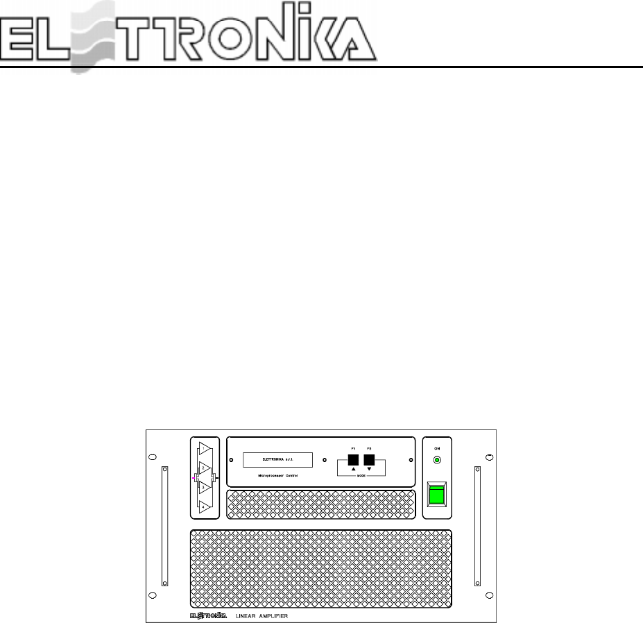
LDMOS - UHF AMPLIFIER
AUTV/2000LD
User’s manual
O
MICROPROCESSOR CONTROLLED SYSTEM
RS232
POWER

12
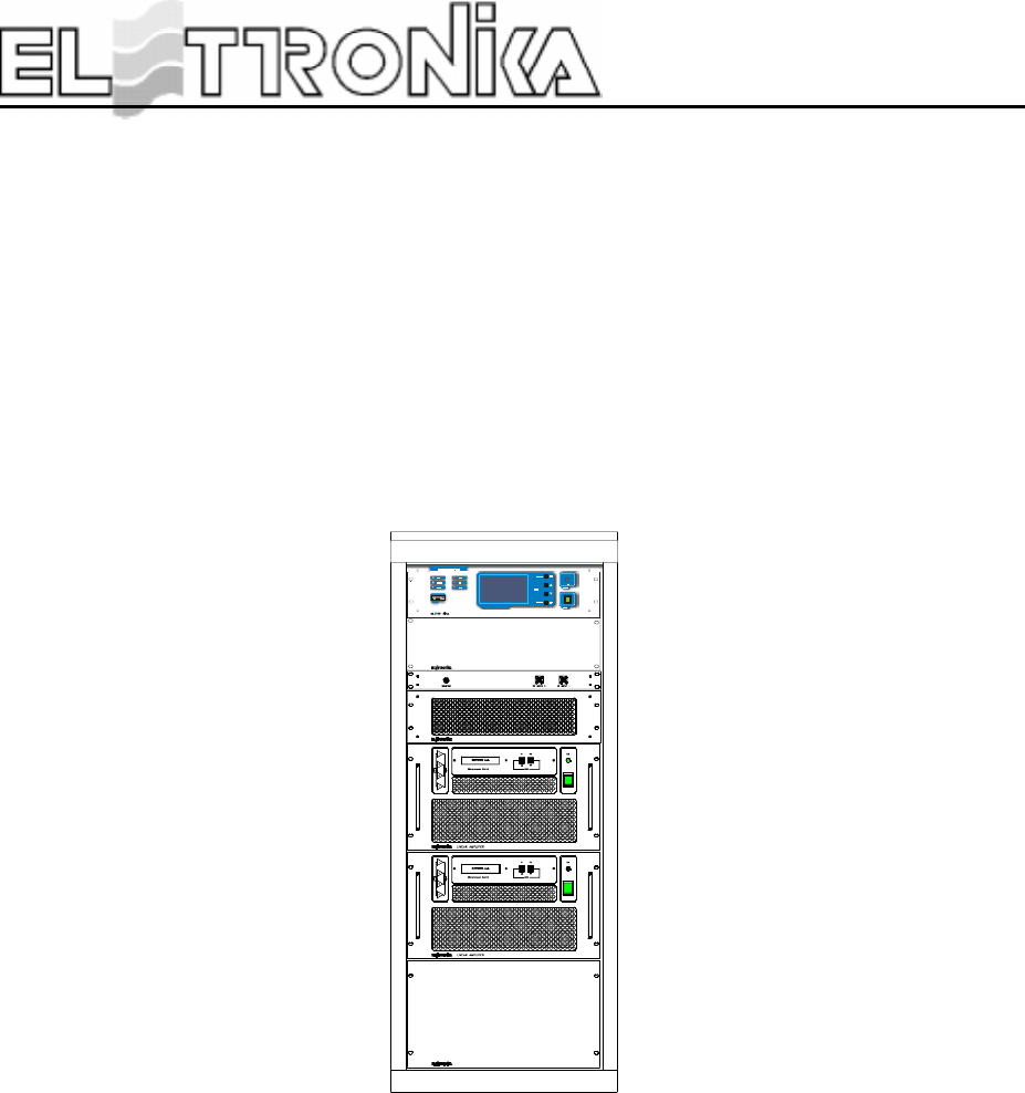
AUTV/2000LD
LDMOS - UHF TV AMPLIFIER
DESCRIPTION
The AUTV/2000LD is a TV amplifier that can be used in the IV/V Bd UHF. Tutti gli stadi di amplificazione
utilizzano componenti con tecnologia LDMOS, ottenendo eccellenti prestazioni in termini di guadagno e
soprattutto di linearità.
Thanks to the high-quality components used and the strong structure it can be used even in the most hostile
environments with the minimum maintenance.
It is composed by two amplifiers AUTV/1000LD coupled by means of 3dB/90° hybrid couplers ensuring an
high insulation between the apparatuses and a very good input return loss.
The amplifier AUTV/2000LD has been designed using advanced technologies made for broadcasting appli-
cations. All of its components have been tested with thermic shocks in order to obtain a very high reliability
and an high MTBF.
A microprocessor control unit controls the apparatus, checking the thermic, electric and RF parameters,
intervening in case of problems and showing the whole functioning status on a large LCD display.
The purity of the spectrum is ensured by a band-pass filter which removes all the out-of-band spurious
emissions far beyond the level required by the regulations.
The transmitter is provided with linearity pre-corrector to compensate the distortions of the final stage.

13
TECHNICAL CHARACTERISTICS
RF SECTION
Frequency range 470 - 860MHz
Vision/Sound amp. Common
Output power 2000W peack sync.
Output power control Automatic or manual (switch-selected)
Output frequency stability 2,5ppm (option 0,05ppm)
Out stage technology LDMOS Solid State
I.M.D. < -54dB(with IF-Precorrector)
Spurious and harmonics level < -60dB
RF Output impedance 50Ω
RF Output connector EIA 7/8”
Intermediate frequency 38.9 or 45.75MHz on request
SOUND SECTION
Input level 1Vpp (adj.)
Input impedance 600Ω Balanced
Input connector Twinax
Pre-emphasis 50µs
Frequency response 30Hz - 15kHz, ±0.5dB
Total harmonic distortion < -0.5%
FM Signal noise ratio > -68dB
(referred to +/-50kHz dev. f = 400Hz) > -60dB (unweighted)
VIDEO SECTION
Input level 1Vpp
Input impedance 75Ω
Return loss 26dB
Differential gain < 5%
Differential phase < 5°
Group delay ±40ns
Input connector BNC Female
Sideband spectrum response According to the standard
Amplitude frequency response According to the standard
GENERAL
Power supply 230Vac, ±10%, 50/60Hz
400Vac 3P+N (on request)
RS232 Socket DB9 Connector (on Amplifier Control)
Telemeasuring socket DB25 Connector (on Amplifier Control)
AGC Socket DB9 Connector (on Amplifier Control)
I2C BUS Socket 2xDB9 Connector (on Amplifier Control)

14
Ambient temperature -5° to +45°C
Humidity 20% - 90%
Cabinet Rack 19”-28U
Dimensions 560x1000x1460mm
Weight 300kg
PROTEC. THR. (AUTV/1000LD)
FWD Power 1200W
REF Power 100W
Temperature 70°C
IDCDRIVER 12A
IDCAMPLIFIER 20A
VDCDRIVER 31V
VDCAMPLIFIER 33V

15
Part Name Code Description Qty
APT084ASF CASSETTO AMPLIF. UHF 1kW LDMOS 220V 2
APG016A CARICO FITTIZIO 50Ω 1kW UHF 1
06641 BAND PASS FILTER UHF 1kW CL4NL22 7/16 1
APG012B CASSETTO CONTROLLO AMPLIFICATORE 1
06816A ACCOP. 3dB IBRIDO 2.5kW UHF m/f 1
MTG0045AR0 ACCOP. DIR. CON PRELIEVO -50/-40dB 1
CMS6006 CAVO 1/2” DA 1mt CONN. 7/16(M) BN203391 1
CMS6007 CAVO 1/2” DA 2mt CONN. 7/16(M) BN203388 1
06811B ACCOP. IBRIDO 3dB 300W CON CARICO 20W 1
02408 SP 10/12 90° 7/16 M+F 90° 1
08510 CABLE RG213 50Ω3,20
02201 CONNET. Nm x RG213 GE 15015 C4 5
02230 R161270000 (N flg. RG213) 1
08504 CABLE RG58 50Ω5,50
02015 R141082161 BNC A CRIMP. x RG58 5
02502 J01150A0041 SMA x RG58/c 1
02576 TAPPO RIV. CON HP 2800 2
02205 NM 90° x RG58 CRIMPARE GE 15142 D/60 2
08503 CABLE RG303 50Ω0,20
07625A CONDENSATORE 3uF CON FILI 1
07620 GRIGLIA ALTA G025001-00-01 1
07625 VENTOLA EBM A2E250-AM06-13 1
07622 BOCCAGLIO BOCC. 250 AL 1
02871 CALOTTE PER DB9 cod. 525-2620 2
02791 CONNETTORE DB9M x CAVO 525-2600 2
V0762 TAPPI NERI O 15.9 PLASTICA DP-625 1
M0800 GUIDA DIN PROFILATA OMEGA Z002 SEM 3
V0958 ACCESSORIO GUIDA DIN ELECO E205 6
05597 POST. x RACK 28U VER CON0099R0 1
CON0057 CON0057R1 CHIUS. SUP. RACK PER AUTV 2kW 1
Z0500 TAV. 1081/E GUIDA RACK 3000W P.2328 ZN 10
DET0462 DET0462R0 BARRA x RACK SOSTEGNO PCAV ZN 2
DET0434 DET0434R2 ANCORAGGIO FLANG. 7/8 CON RACK 1
DET0391 DET0391R0 BARRA FISS. ACC. INP AUDIO 5kW 1
DET0538 DET0538R0 PIASTRA ANCOR. ACC. DIR. FIL. 2kW 1
DET0537 DET0537R0 PIASTRA ANCOR. ACC. DIR. FIL. 2kW 1
DET0536 DET0536R0 ANGOLARE FISS. FILTRO 2kW COMT. 2
DET0535 DET0535R0 BARRA FISS. FILTRO 2kW COMT. 2
V0962 MORSETTIERA/GIUNZIONE ELECO E806 3
09627 CASSETTO TRASF. SEPARAT. DI RETE 8kVA 1
07627B SPINA PROT.B.T. 32A 2P+T 220V GW60015 1
07627C PRESA VOL. 32A 2PT 220V GW62015 1
R0154 RACK 28U 565x1000 1
PAN0017 PAN0017R0 PANNELLO AVANTI DIETRO 1
02571 CARICO BNC 1/2W 50Ω2
Component list APT088A - AUTV/2000LD

16
This page is intentionally blank
17
AMPLIFIER CONTROL
O
MICR O PR O CESSO R CO N TROLLE D SYS TEM
RS232
PO W ER
CODE: APG012B TITLE: AMPLIFIER CONTROL REV: 0 DATE: 25/11/02
18
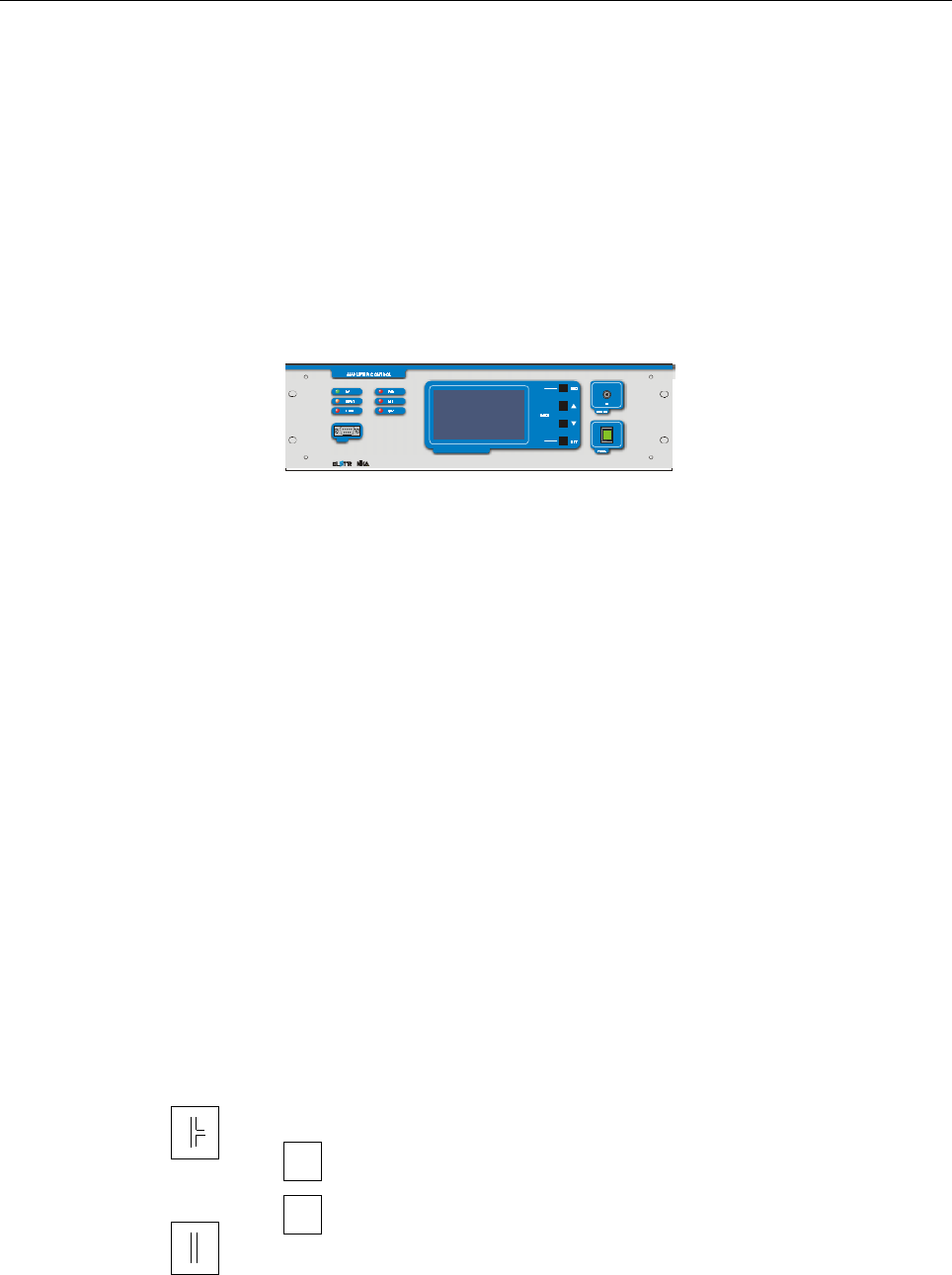
1.1 FUNCTIONS
The control system is made up by some “Slave” boards, which check locally the amplifier modules,
and a “Master” board to monitor the status of the Slave boards in each module and show on a graphic
display all the checked parameters. The number of the Slaves changes depending on the output power of
the amplifier. The communication between Master and Slaves is made via I2Cbus standard. The Master
board reads the overall parameters of the equipment (forward and reflected power and unbalancing),
polls (interrogates in sequence) the local boards, shows on the display the values requested by the user
and indicates alarm conditions, if any. Besides it realizes a serial data interface to an external system
able to analyse the working parameters of the equipment, using the RS232 and RS485 communication
protocols.
At start-up, the display of the Amplifier Control shows an informational message concerning the equip-
ment and the firmware version.
The main menu has: a list of the amplifier modules, the measure of some parameters of the powers in antenna,
a window with icons to show the alarm status and some general information, that is date, time, temperature
inside the module and, for FM equipment, transmission frequency.
In the Amplifier List, next to each module, you can find the following symbols:
AMPLIFIER CONTROL
if the communication with the slave is correct and then
if the communication with the slave is interrupted
ON
if the amplifier module is OFF
OFF
if the amplifier module is ON
O
MICR O PRO CE SSO R CO N TROLL E D SYS TEM
RS232
POW ER
19
The UP and DOWN arrow keys allow to select one of the slave or the alarm list; the RET key is used to
confirm the selection.
By selecting one of the slaves, it is possible to see all the parameters of that amplifier module, that is voltages
and currents of the power supply, forward and reflected power, temperature and, for some amplifiers,
unbalancing powers. The UP and DOWN keys allow to scroll the local measures of all the slaves. The ESC
key is used to go back to the main menu.
By selecting the Alarm List, two pages listing the latest 20 alarms saved are shown. Each line in these pages
includes the progressive number of the alarm, starting with the most recent, the number of the module in which
the alarm occurred (the indication “AC” means that the alarm occurred in the Amplifier Control module), the
parameter in alarm and the date and time of the alarm. The saved alarm can be deleted by keeping simultane-
ously pressed the UP and DOWN keys. The ESC key is used to go back to the main menu.
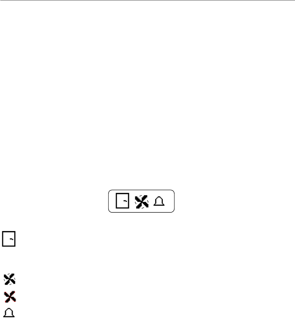
In the main menu there is the Alarm Status Window:
displays the status of the INTERLOCK, in case of alarm this icon blinks and the buzzer rings.
The INTERLOCK signal is a control available to the user to manage an On/Off sensor.
When the relevant PIN is grounded, the Master board does not signal any alarm, as soon as the
PIN is left floating, an alarm is detected;
shows the status of the FANS: works normally;
in case of alarm this icon blinks and the buzzer rings;
this icon blinks in case of ALARM.
If one of the parameters of a Slave or any of the ones directly checked by the Master is alarmed, the
general alarm LED and the alarm icon blink until the Alarm List is checked to see the type of alarm
occurred.
Besides, if an alarm for any of the powers of the signals in antenna occurs, the relevant measure in the
Antenna window of the display and the relevant LED on the front panel of the Master module blink until the
measure decreases below the threshold level, determined by the nominal power of the amplifier.
If the slave modules are working and an INTERLOCK or FANS alarm occurs, aside from the indication
explained above, the amplifiers are switched off. This happens immediately after an INTERLOCK alarm, or
about 7 seconds after a FANS alarm is detected.

20
In case the amplifiers are communicating but switched off, or they are not communicating and the INTER-
LOCK alarm contact is open, a WARNING condition occurs: buzzer on and blinking ALARM LED on the
front panel; while if it is the FANS alarm contact to be open, the icon of the alarm appears in the box.
Further to any of these two alarms it is possible to choose whether to turn off or not the amplifiers. In fact, if
the DIP-switch n. 2 (see mounting plan BOTTOM - SCH0109BR0) is set to OFF before turning on the
transmitter, the amplifiers will be switched off after a FAN alarm occurs, while it will be kept on if the switch
is set to ON. The DIP-switch n. 3 has the same effect for what concerns the Interlock alarm.
1.2 PROGRAMMING MODE
To access the “Programming Mode”, press simultaneously the ESC and RET keys. The “Setting Time”
menu or the “Setting Frequency” menu can be selected by using the arrow keys, while the RET key confirms
the choice. While this menu is open, no alarm will be signalled until the return to the main menu. If no key is
pressed for about 50 seconds, the main menu is automatically displayed.
The Setting Time menu allows to set the following functions: hour, minute, day, month and year. The selected
parameter blinks and can be modified with the arrow keys; the RET key confirms the changes, while the ESC
key cancels them.
The “Setting Frequency” menu appears only in the FM amplifiers. To visualize the power emitted by the
antenna correctly, set the frequency nearest to the working frequency of the transmitter in the frequency
programming menu. The selected parameter blinks and can be modified with the arrow keys; the RET key
confirms the changes, while the ESC key cancels them.
1.3 SETTING
Set the RS232-RS485 mode on the SCH0109BR0 Control board:
RS232 MODE - DIP-switch n. 1 set to ON before turning on the transmitter: the RS232 mode allows a
direct access to the equipment via PC and a remote access via modem or switched telephone line.
RS485 MODE - DIP-switch n. 1 set to OFF before turning on the transmitter. ThevRS485 mode allows a
remote access to the equipment via modem over switched telephone line or GSM network. It allows the
connection to the Remote Control System, designed to monitor several apparatuses located at the same site.
- FWD Power calibration
Disconnect the antenna and connect a wattmeter to the antenna connector. Give power to the amplifier until
you will read on the wattmeter a value corresponding to the equipment nominal power. Then turn the trimmer

21
A (see mounting plan BOTTOM - SCH0109BR0, it is a variable resistor used to adjust the A analog input
measure) until you read approximately the same FWD power value on the display.
- REF Power calibration
Disconnect the antenna and connect a wattmeter to the antenna connector. Connect the Forward power
monitoring cable to the Reflected power input connector. Give power to the amplifier until you will read on the
wattmeter a value corresponding to 10% of the equipment nominal power. Then turn the trimmer B (see
mounting plan BOTTOM - SCH0109BR0, it is a variable resistor used to adjust the B analog input measure)
until you read approximately the same REF power value on the display.
- UNB Calibration
Connect a wattmeter before the dummy load. Give power to the amplifier then turn off one slave
module: you will read an amount of unbalancing power on the wattmeter. Turn the trimmer C (see mounting
plan BOTTOM - SCH0109BR0, it is a variable resistor used to adjust the C analog input measure) until you
read approximately the same UNB power value on the display.
1.4 REMOTE CONTROL
It is possible to remotely control the apparatus, thus to monitor the parameters shown on the display of the
Amplifier Control and check the status of the transmitter. This is done through RS232 and RS485 standard
serial communication, digital and analog inputs through the DB25 telemetering connector on the rear panel of
the Amplifier Control.
The pins n. 1 and n. 14 of this connector are used to receive the ON (pin n. 1) and OFF (pin n. 14)
commands, both impulsive and stationary. The digital level on these contacts is usually high, becoming low
when the remote control is active. When a remote command to turn off the amplifiers is received while the
transmitters is ON, the LED ON of the frontal panel blinks and the REMOTE LED lights up.

22
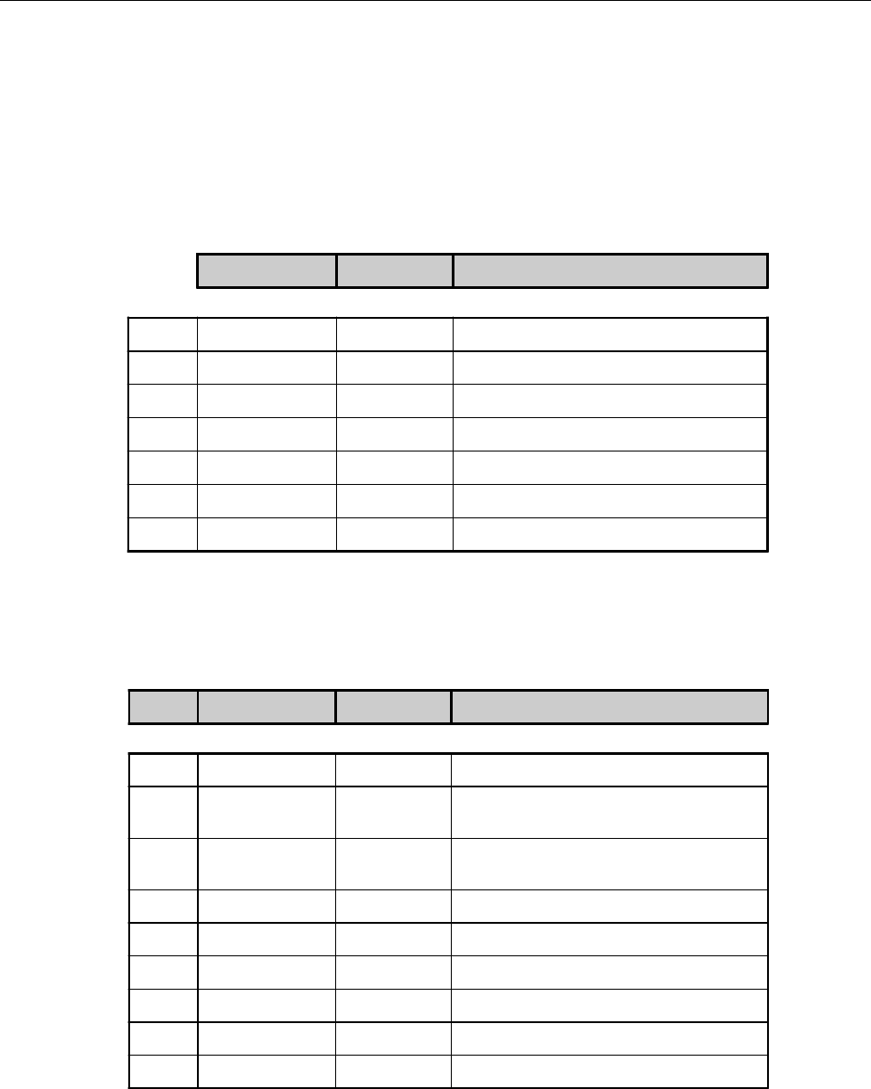
PIN N° SYGNAL TYPE IN/OUT FUNCTION
1- - -
2 Digital Input RX232
3 Digital Output TX232
4 VDC +12V - -
5GND - -
6 VDC +12V - -
7- - -
8- - -
9- - -
PIN N° SYGNAL TYPE IN/OUT FUNCTION
1GND - -
2 Digital Input RX2_485B-
3 Digital Input RX2_485A+
4 VDC +12V - -
5GND - -
6 VDC +12V - -
7 Digital Output TX2_485Z-
8 Digital Output TX2_485Y+
9- - -
1.5 RS232 AND RS485 PIN TABLES
RS232 - DB9 Connector
RS485 - DB9 Connector

23
1.6 TELEMEASURING PINS TABLE
PIN N° SIGNAL TYPE IN / OUT FUNCTION
1 Digital - REMOTE ON/OFF TTL:
GND = REMOTE ON
+5V = REMOTE OFF
2 Digital Output -
3 Digital Output -
4 Digital Output -
5 Digital Output -
6 Digital Output -
7 Digital Output AGC alarm TTL:
GND = AGC alarm, +5V = no AGC alarm
8 Digital Output -
9GND - -
10 Analog Output -
11 Analog Output -
12 Analog Output -
13 Analog Output -
14 Digital Input
REMOTE AMPLIFIER ON/OFF TTL:
if REMOTE ON then
GND = AMPLIFIER OFF
+5V = AMPLIFIER ON
15 Digital Output -
16 Digital Output -
17 Digital Output -
18 Digital Output -
19 Digital Output AGC alarm TTL:
GND = AGC alarm, +5V = no AGC alarm
20 GND - -
21 +5V - -
22 Analog Output FWD Power [0,+ 5V]
23 Analog Output REF Power [0,+ 5V]
24 Analog Output UNB Power [0,+ 5V]
25 Analog Output -
24
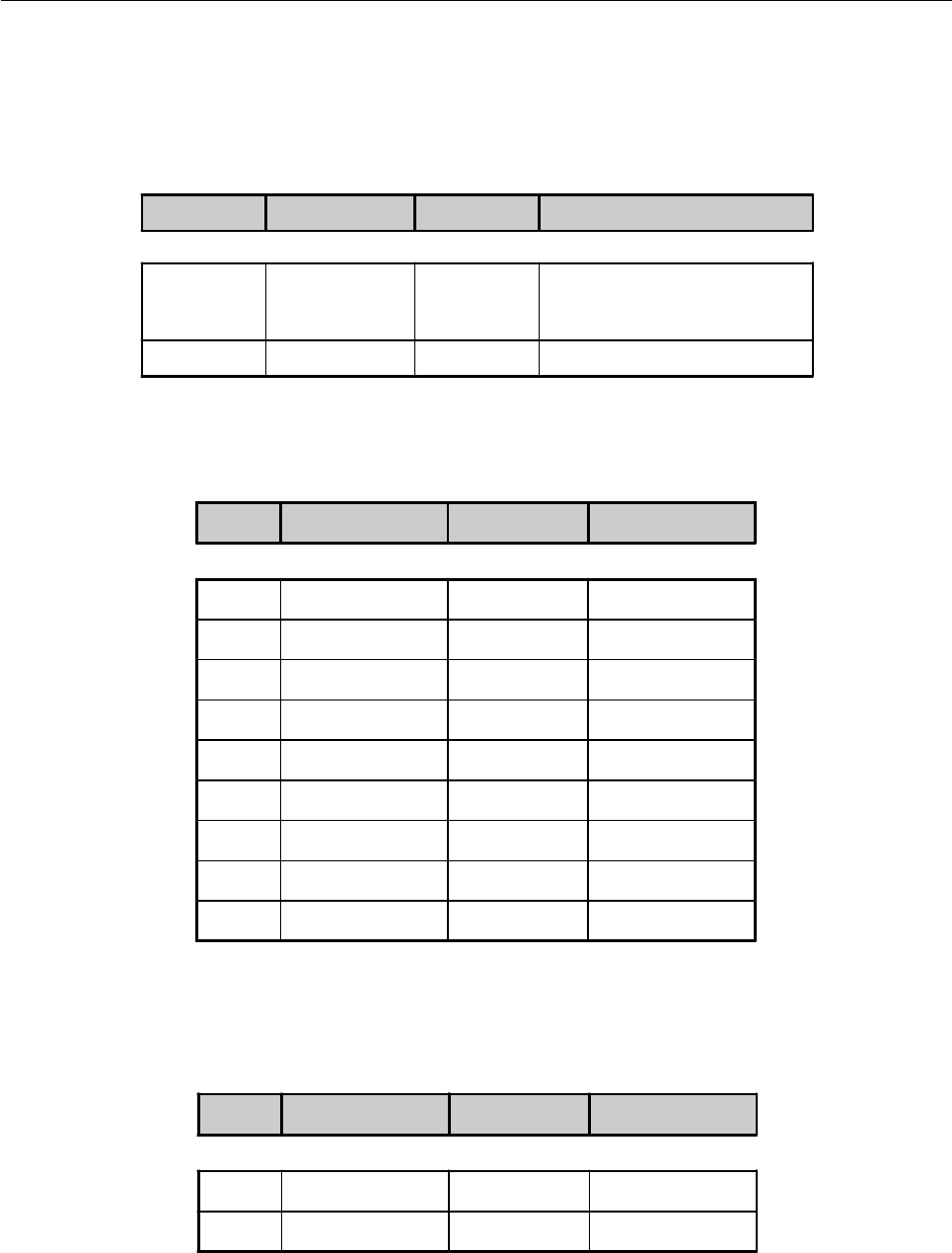
1.7 OTHER TABLES
BNC Connectors
AGC Connector
SYGNAL TYPE IN/OUT FUNCTION
A Analog Input FWD Power monitoring
B Analog Input REF Power monitoring
C Analog Input UNB Power monitoring
D- - -
E- - -
F- - -
G- - -
PIN N° SYGNAL TYPE IN/OUT FUNCTION
1GND - -
2 Digital Output AGC alarm TTL:
GND = AGC alarm, +5V = no AGC alarm
3 Digital Output AGC alarm TTL:
GND = AGC alarm, +5V = no AGC alarm
4- - -
5- - -
6- - -
7- - -
8 Analog Output FWD Power (range 0 - +5V)
9 Analog Output FWD Power (range 0 - +5V)
25
FANS CONTROL
I2C BUS Connector
PIN N° SYGNAL TYPE IN/OUT FUNCTION
1GND - -
2VDC +24V - -
24VDC LOAD FAN Connector
BNC SYGNAL TYPE IN/OUT FUNCTION
Contact Digital Input FANS control Switch or TTL:
closed/GND = no FANS alarm
open/+5V = FANS alarm
Body GND - -
PIN N° SYGNAL TYPE IN/OUT FUNCTION
1- - -
2 Digital Output SCL
3GND - -
4 Digital Output SDA
5- - -
6- - -
7- - -
8- - -
9- - -
26
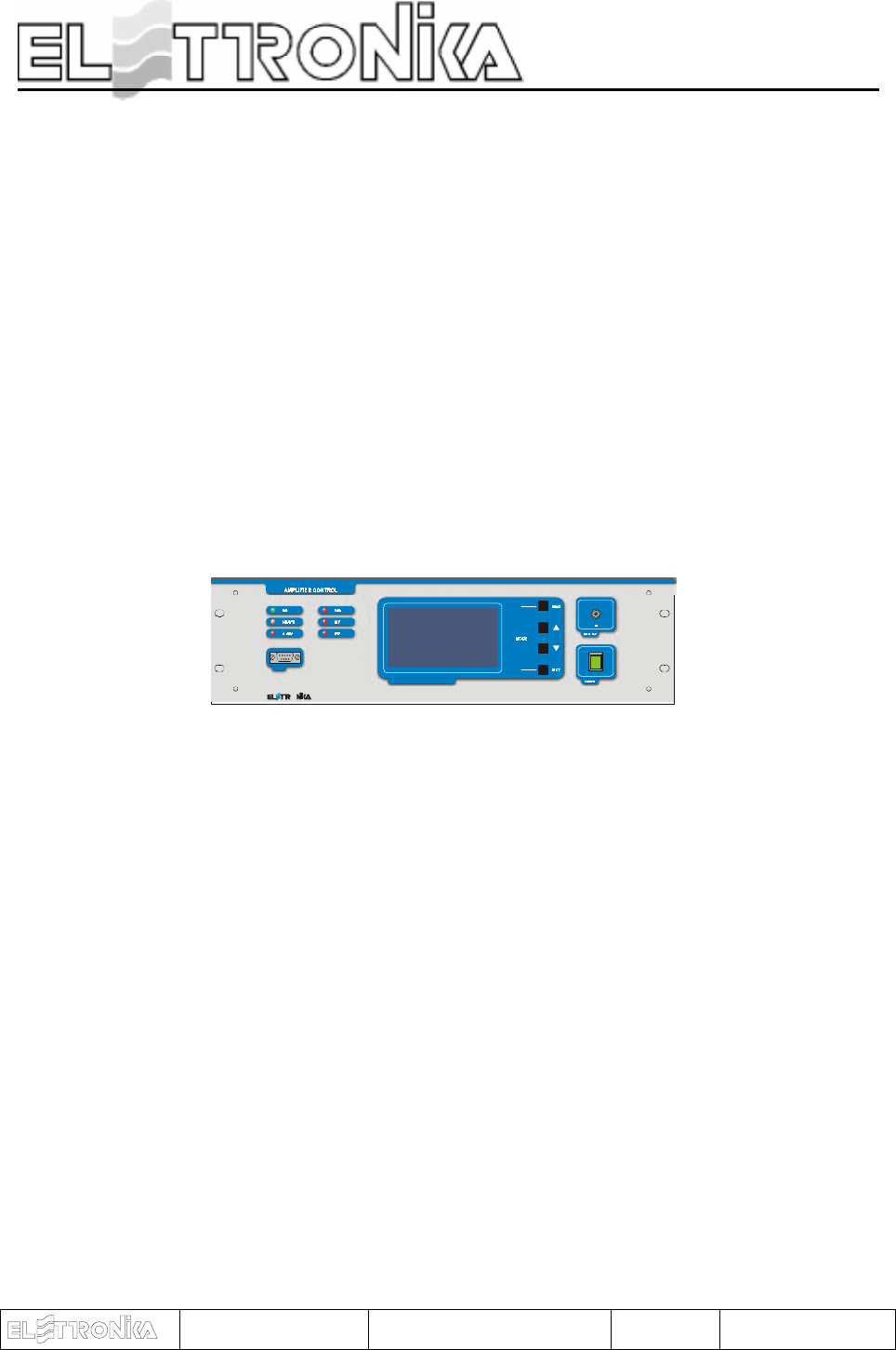
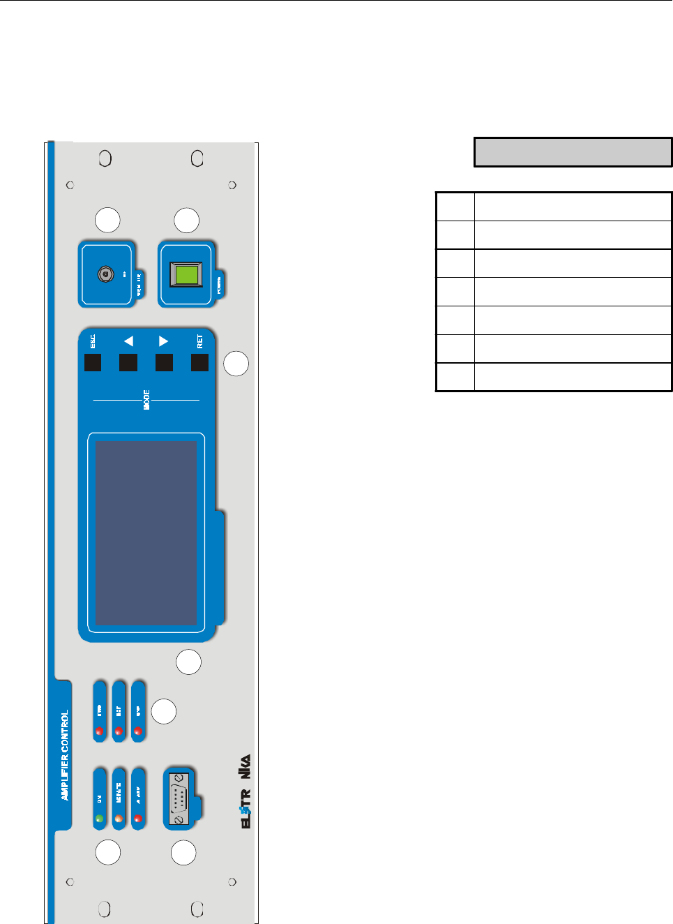
Frontal panel
O
MI C RO PR O C ESS OR CO N TR OLL ED SY STEM
RS232
POWER
1
34
5
6
7
2
DESCRIPTION
1Status LEDs
2Alarm LEDs
3 RS232 Socket
4 LCD Display
5 Function keys
6 RF Monitor connector
7ON/OFF Switch
27
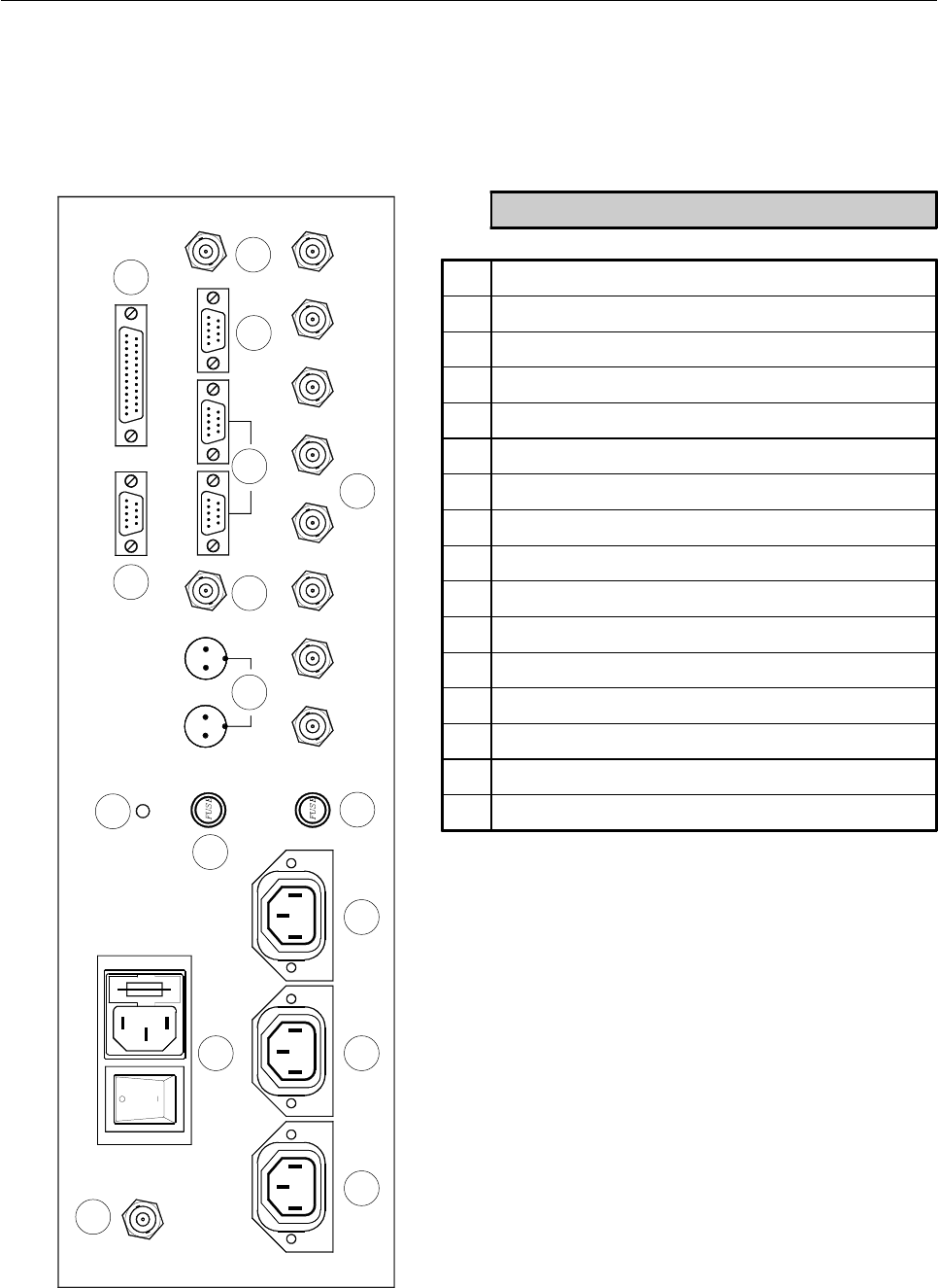
Rear panel
1
2
3 4 5
6
7
816
9 12 13 14 15
10 11
DESCRIPTION
1 RF Input connector
2 Main Power supply socket with Fuse-Holder by 10A
3 Driver1 Power socket
4 Driver2 Power socket
5 Fans Power socket
6GND
7 Fuse by 1A
8 Fuse by 8A
9 24Vdc Connectors
10 AGC Socket
11 Telemeasures socket
12 Fans Control connector
13 I2C Bus connectors
14 RS485 Socket
15 Interlock connector
16 Power measurement connector

28
This page is intentionally blank

29
Part Name Code Description Qty
CON0145 CON0145R0 POST.CASS.CONTROLLO APG012B 1
05504 CON0134R0 PIANO prof.260 ARE.p.02047 ZN 1
05525 LAT. 3U PROF.260 TAV.424/A p.2033 ZN 2
PAN0066 PAN0066AR0 PANNELLO CONTR.APG012B 3U 1
CON0135 CON0135AR0 BASE CASS.CONTR.X APG012 ZN 1
05552B KIT MANIGLIE 3-4U cod 235.12 2
02880 SPINA VDE 10A + INT.+FUS DA PANN.BZ15011 1
SCH0109BR0 SCHEDA MASTER CON DISPLAY 1
SCH0110BR0 SCHEDA 3 IN.ANALOGICI MASTER APG012B 1
SCH0152AR0 SCHEDA COMMUTAZIONE 220VAC X APG012B 1
SCH0153AR0 SCHEDA IN/OUT DIGITAL SIGNAL X APG012B 1
E0016 ALIM. SWITCHING S-50-24 1
07926 PROTEZIONE IN GOMMA PVC PG 987 1
02843 SPINA SCHERM. 2 POLI cod. 525.2552 2
02844 PRESA SCHERMATA 2 POLI cod.525.2542 2
02695 CONNETTORE DB9F X CAVO 525-2810 1
02856 CONNETTORE DB25F X CAVO 525-2812 1
07925 PROTEZIONE IN GOMMA PVC PG 075 1
07524A INTERR. NERI I3910 1
02018 GE 35145D/22 BN(UG909/cxRG174) 1
02035 PRESA BNC/F X RG 316 COD.60140 1
08500 CAVO RG 174 50Ohm 0,3
02700 CONNETTORE COD.534-2303 FEM.16 VIE 1
Component list APG012B - Amplifier Control

30
This page is intentionally blank
31
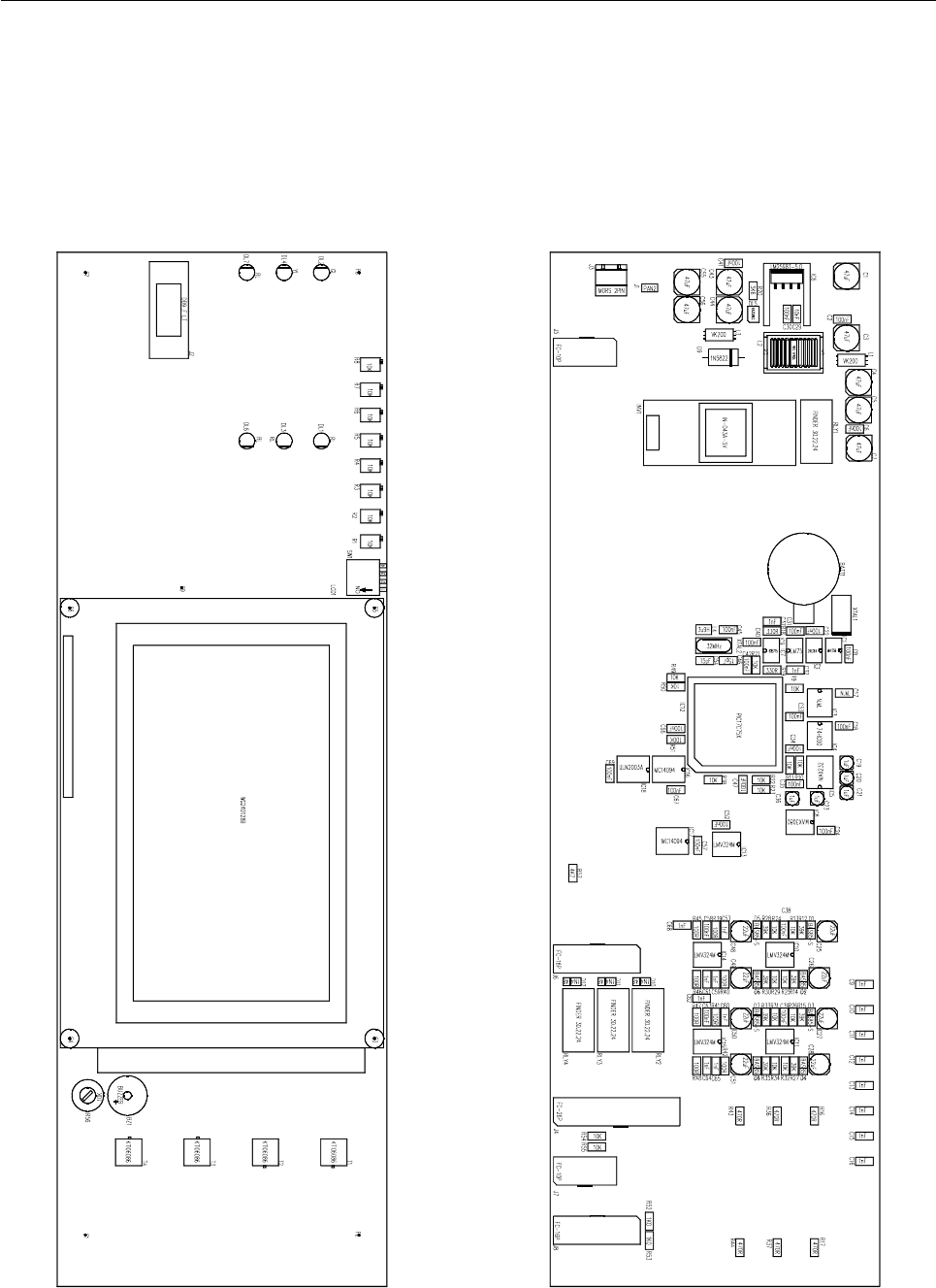
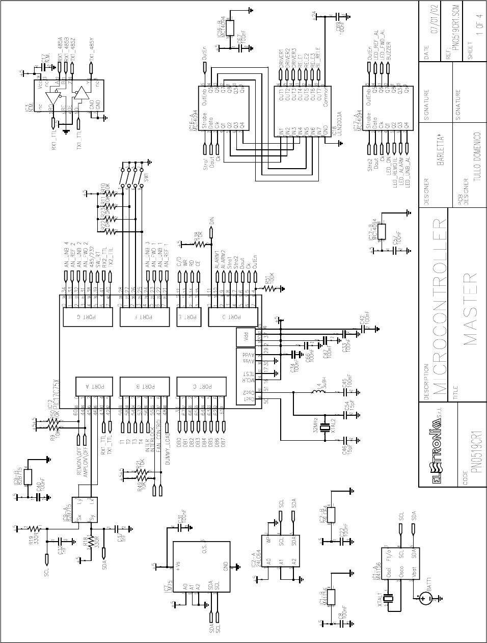
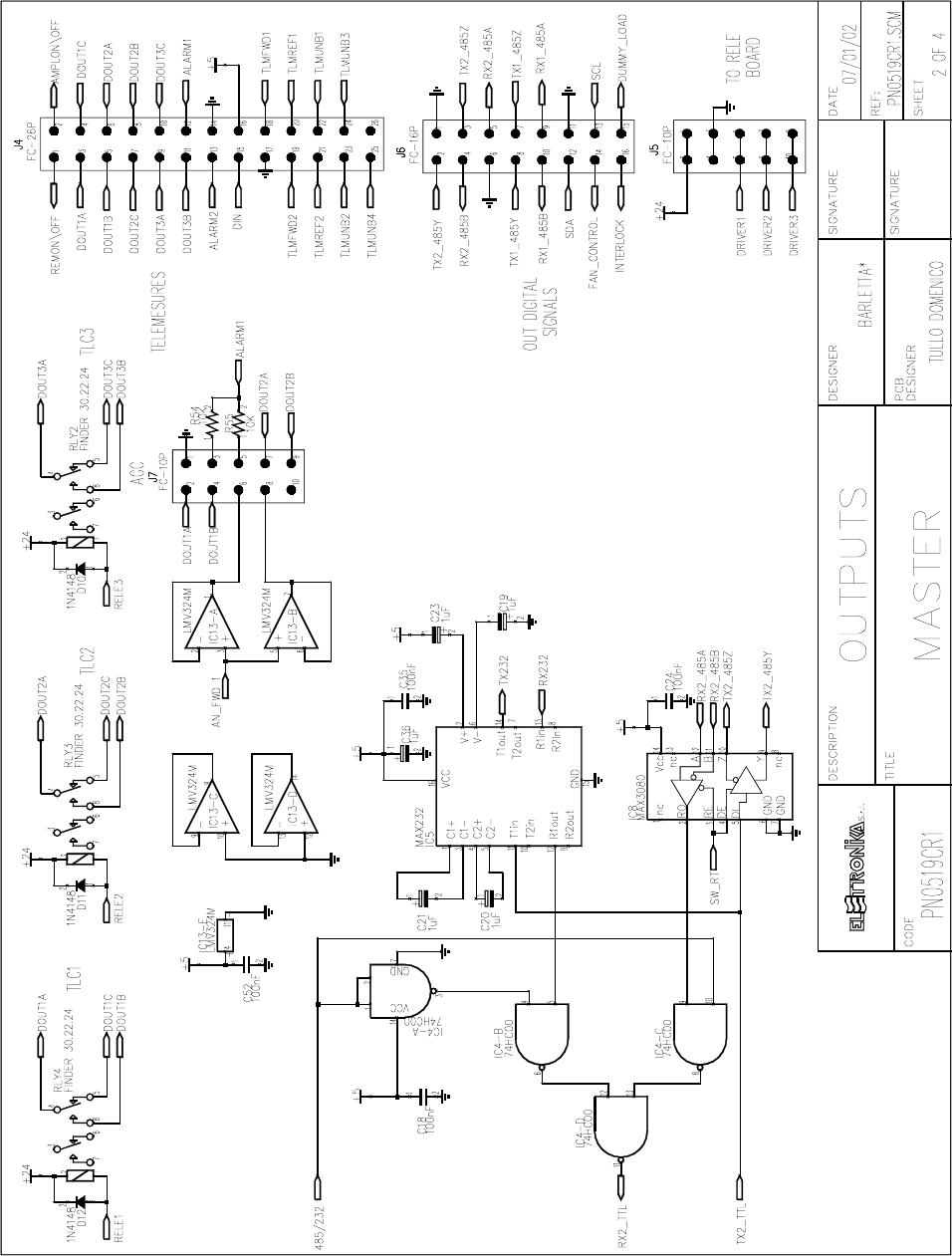
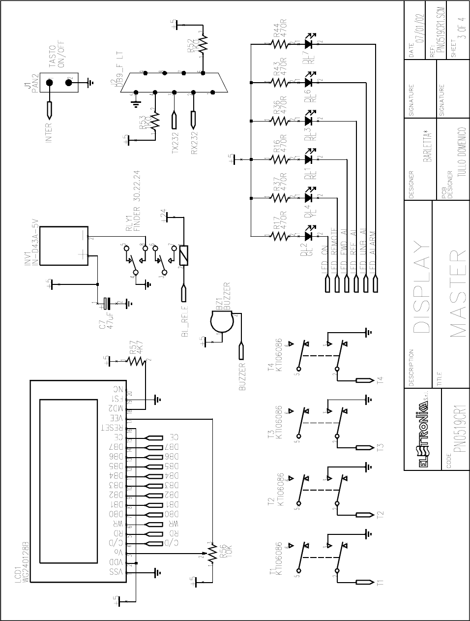
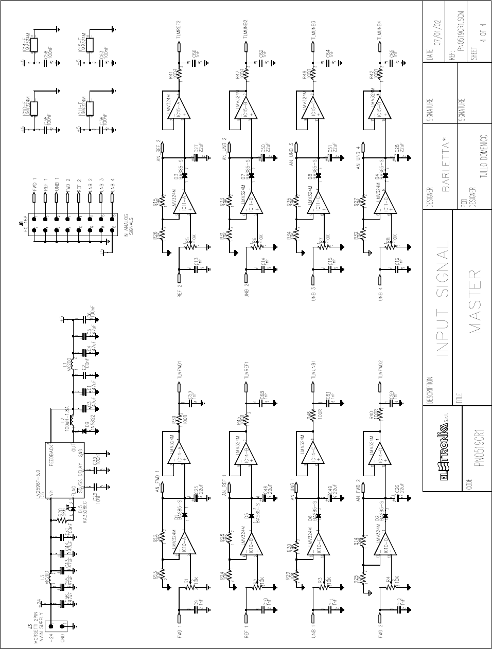
MASTER BOARD SCH0109BR0
Component layout SCH0109BR0 (Bottom and Top layer)
32
33
34
35

36
COMPONENT LIST SCH0109BR0
Part Name/Number Description Qty. Comps. Page 1/3
BATT BH001RB 3093_90 03093 03090 BATTERY HOLDER 1 BATT1
BZ AI-155 03705 03705 5VDC BUZZER 1 BZ1
CC 100nF-S 01065C 01065C Y5V 1206 COND 25 C2
C6
C8
C18
C22
C24
C30-31
C33-35
C38-42
C45
C47
C52
C57-58
C63
C66-67
C69
CC 10nF-S 01053B 01053B SMD 1206 COND 1 C29
CC 1206 NOT MOUNTED NOT MOUNTED SMD 1206 COND 1 C17
CC 15pF-S 01088 01088 SMD 1206 COND 2 C46
C54
CC 1nF-S 01096 01096 SMD 1206 COND 18 C9-16
C32
C37
C53
C59-62
C64-65
C68
CE 1uF50V-S 01763A 01763A ELETTR SMD COND 5 C19-21
C23
C36
CE 22uF35V-S 01782A 01782A ELETTR SMD COND 8 C25-28
C48-51
CE 47uF50V-S 01791C 01791C ELETTR SMD COND 9 C1
C3-5
C7
C43-44
C55-56
D 1N4148-S 03002 03002 SMD DIODE 3 D10-12
D 1N5822 03022 03022 SCHOTTKY DIODE 1 D9
D BAS85-S 03024 SMD DIODE SCHOTTKY 8 D1-8

37
Part Name/Number Description Qty. Comps. Page 2/3
DIS WG240128B 03083 240/128 DOT MATRIX LCD 1 LCD1
DL KA-3528EC 03056 03056 RED SMD LED DIODE 1 DL5
DL LEDG3 03053 03053 GREEN LED DIODE 3mm 1 DL2
DL LEDR3 03058 03058 RED LED DIODE 3mm 4 DL1
DL3
DL6-7
DL LEDY3 03051 03051 YELLOW LED DIODE 3mm 1 DL4
IC 24LC64 04815 04815 SMD INTEG CIRCUIT 1 IC2
IC 74HC00-S 4762A 4762A SMD INTEG CIRCUIT 1 IC4
IC 82B715-S 04734A 04734A SMD INTEG CIRCUIT 1 IC9
IC LM2598T-5.0 4871 04871 INTEG CIRCUIT 1 IC6
IC LM75-S 00668 00668 SMD INTEG CIRCUIT 1 IC7
IC LMV324M-S 04658B 04658B SMD INTEG CIRCUIT 5 IC10-11
IC13-15
IC M41T56 04611 04611 SMD INTEG CIRCUIT 1 IC1
IC MAX232-S 04804B 04804B SMD INTEG CIRCUIT 1 IC5
IC MAX3080-S 04770 04770 SMD INTEG CIRCUIT 1 IC8
IC MAX3080-S N.M. NOT MOUTED SMD INTEG CIRCUIT 1 IC3
IC MC14094BD 04718 04718 SMD INTEG CIRCUIT 2 IC16-17
IC PIC17C75X 04807A 04807A 7510B---SMD INTEG CIRCU 1 IC12
IC ULN2003A 4870 04870 SMD INTEG CIRCUIT 1 IC18
IND 3u9H-S 05030 05030 INDUCTOR 1 L4
IND T100uH-1.8A 4958 04958 TOROIDAL-STORAGE CHOKES 1 L2
IND VK200 05013 05013 INDUCTOR 2 L1
L3
INV IN-D43A-5V 03085 DC/AC MODULE 1 INV1
J DB9_F-0° LT 02794 PCB CONNECTOR DB9 LONG T 1 J2
J FC-10P 02697-02699 02697+02699 PCB CONNECTOR POL 2 J5
J7
J FC-16P 02701-02700 02701+02700 PCB CONNECTOR POL 2 J6
J8
J FC-26P 02855-02854 02855+02854 PCB CONNECTOR POL 1 J4
J PAN2 02739-40-41 02739+02740+02741 PCB CONNECTO 1 J1
J SCREWCONN2 02853 02853 PCB SCREW CONNECTOR 1 J3
R 100K-S 00065A 00065A RES 1/4W 5% SMD 1206 1 R51
R 100R-S 00029A 00029A RES 1/4W 5% SMD 1206 8 R39-42
R45-48
R 10K-S 00053A 00053A RES 1/4W 5% SMD 1206 19 R9-11
R13
R21-26
R29
R31-32
R34
R38
R49-50

38
Part Name/Number Description Qty. Comps. Page 3/3
R54-55
R 1K0-S 00041A 00041A RES 1/4W 5% SMD 1206 2 R52-53
R 330R-S 00035B 00035B RES 1/4W 5% SMD 1206 2 R18-19
R 39K-S 00060A 00060A RES 1/4W 5% SMD 1206 8 R12
R14-15
R27-28
R30
R33
R35
R 470R-S 00037A 00037A RES 1/4W 5% SMD 1206 6 R16-17
R36-37
R43-44
R 4K7-S 00049A 00049A RES 1/4W 5% SMD 1206 1 R57
R 5K6-1%-S 00050B 00050B RES 1/4W 1% SMD 1206 1 R20
RL 30.22.24 07569 07569 RELE 4 RLY1-4
RV 10K-3266X 00807 00807 VARIABLE RESISTOR 8 R1-8
RV 10K-S-H 00715 00715 VARIABLE RESISTOR 1 R56
SW SWITCH-4DIP 90° 07531A PCB DIP SWITCH 90° 1 SW1
T 06086 N 7630 7632 7630 7632 KTI06086 PULSANTE 2 4 T1-4
XTAL 32.768k-S 05146 05146 QUARTZ 1 XTAL1
XTAL 32MHz-S 05291 05291 QUARTZ 1 XTAL2
39
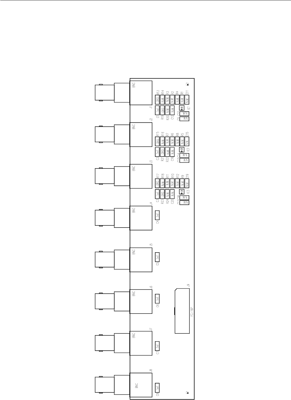
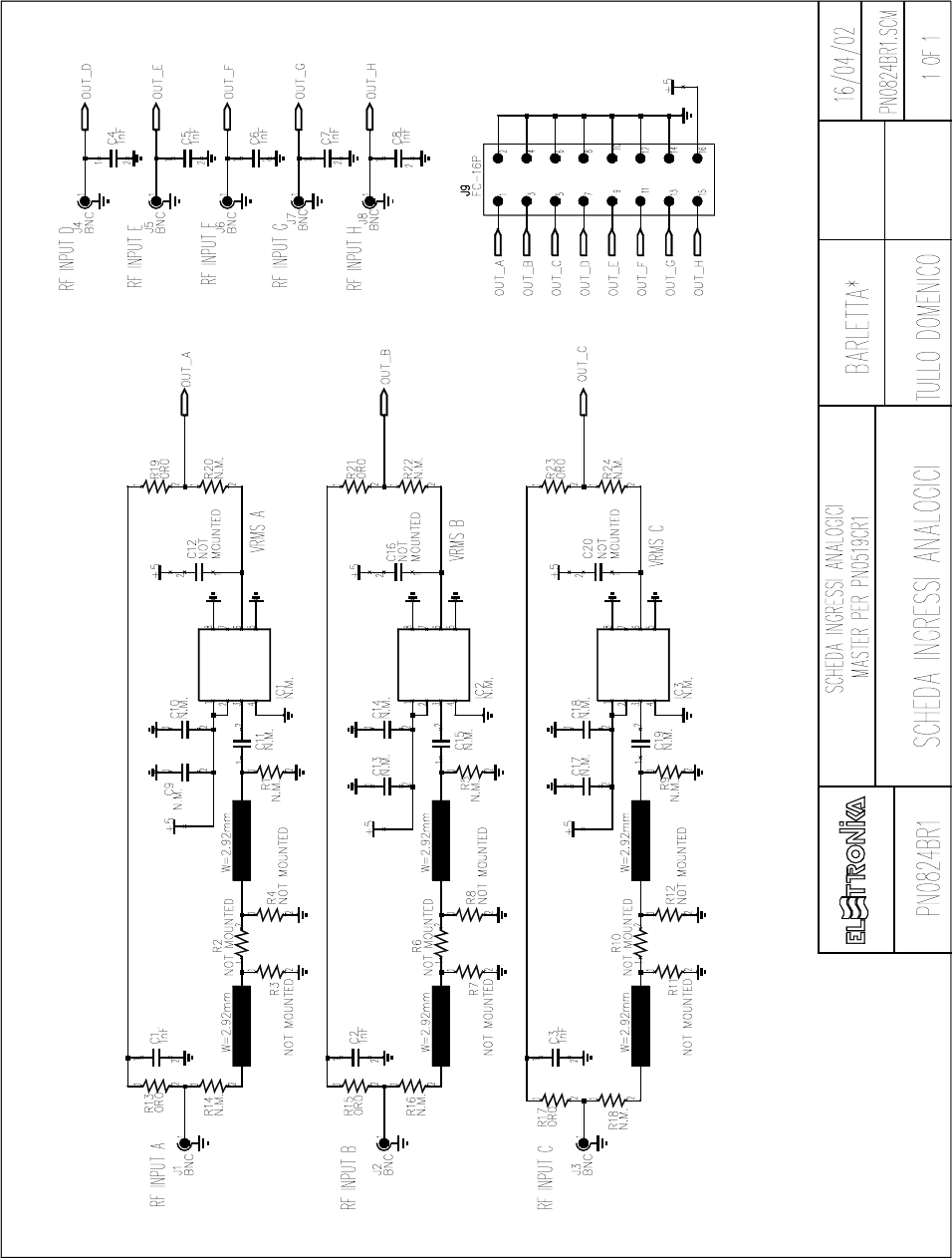
ANALOG INPUT FOR MASTER BOARD SCH0110BR0
Component layout SCH0110BR0
40

41
COMPONENT LIST SCH0110BR0
Part Name/Number Description Qty. Comps.
CC 1206 NOT MOUNTED NOT MOUNTED SMD 1206 COND 12 C9-20
CC 1nF-S 01096 01096 SMD 1206 COND 8 C1-8
J BNC-90G-PCB 2034 02034 PCB CONNECTOR 8 J1-8
J FC-16P 02701-02700 02701+02700 PCB CONNECTOR POL 1 J9
R 0R0-S 00001 00001 RES 1/4W 5% SMD 1206 6 R13
R15
R17
R19
R21
R23
R 1206 NOT MOUNTED NOT MOUNTED RES 1/4W 5% SMD 12 18 R1-12
R14
R16
R18
R20
R22
R24
Z MICRO SOIC 8P N.M. SMD INTEG CIRCUIT NOT MOUNTED 3 IC1-3
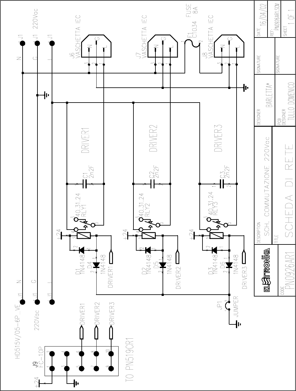
42
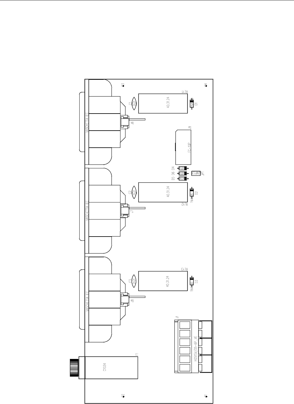
230VAC SWITCHING BOARD SCH0152AR0
Component layout SCH0152AR0
43

44
COMPONENT LIST SCH0152AR0
Part Name/Number Description Qty. Comps.
CC 2nF2 2kV 01045A 01045A CERAMIC COND 3 C1-3
D 1N4148 03001 03001 DIODE 6 D1-6
FUSE OMEGA C1034 FUS00008 PORTA FUSIBILE 5x20 D 1 F1
J CON HD515V/05-6PVE 02883 + 02884 PANDUIT PCB CONN 1 J1
J FC-10P 02697-02699 02697+02699 PCB CONNECTOR POL 1 J9
J VASCHETTA IEC 02879 VASCHETTA FEMALE PCB 3 J6-8
JU JUMP2 02739-02742 02739+02742 MASCHIO PAN2 1 JP1
RL 40.31.24 7567C RELE 3 RLY1-3
45
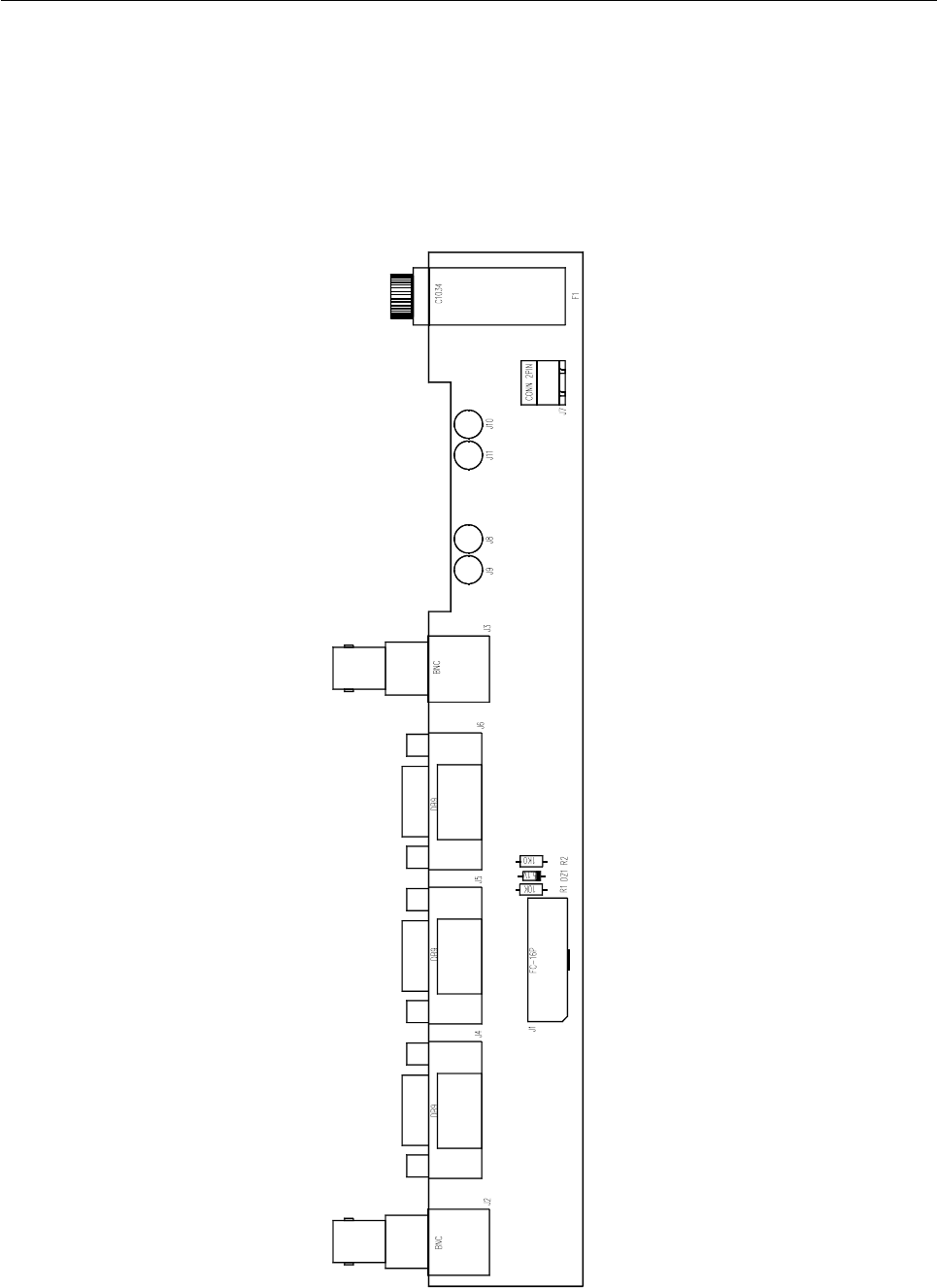
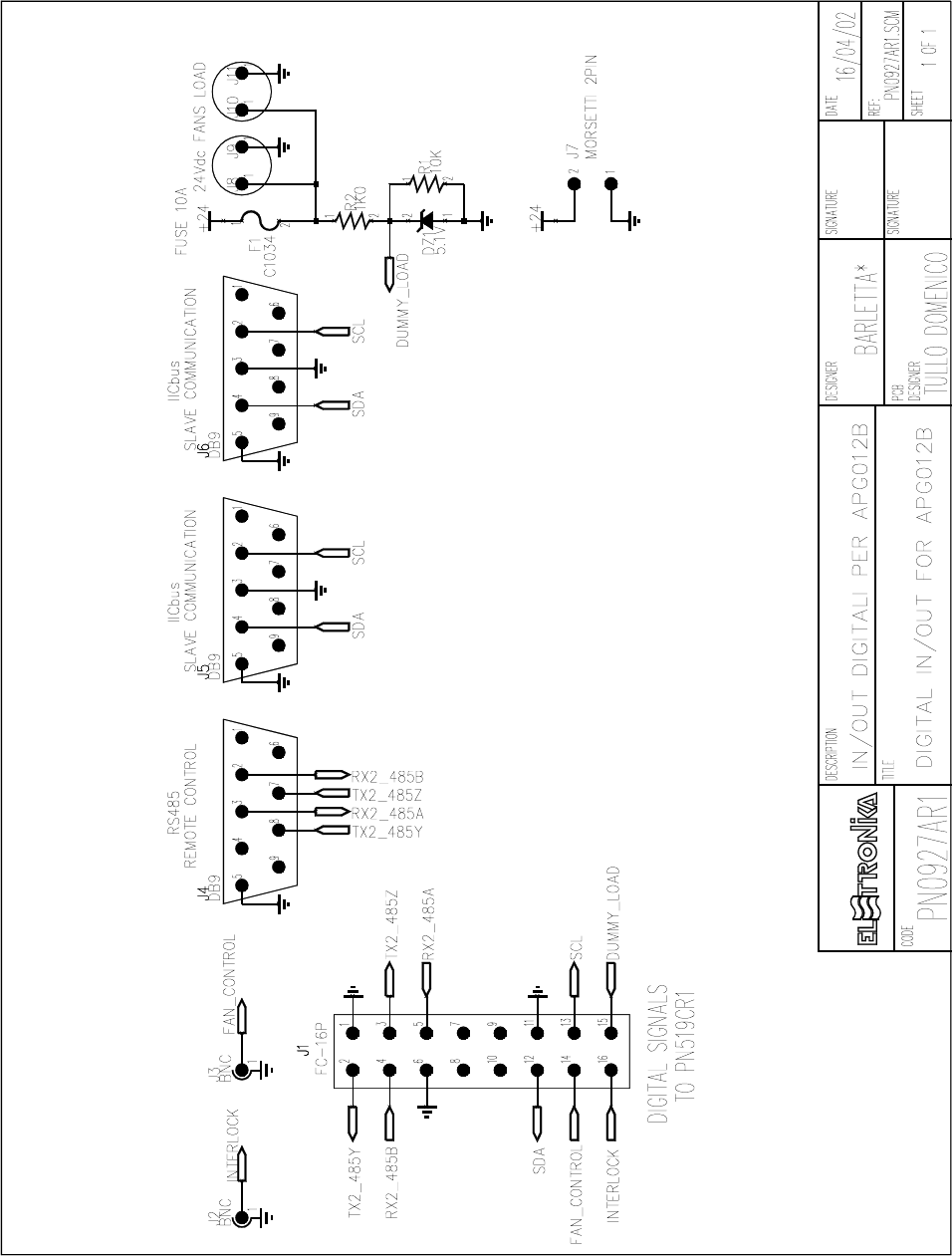
IN/OUT DIGITAL FOR APG012B SCH0153AR0
Component layout SCH0153AR0
46

47
COMPONENT LIST SCH0153AR0
Part Name/Number Description Qty. Comps.
DZ 5V1 03109 03109 ZENER DIODE 1 DZ1
FUSE OMEGA C1034 FUS00008 PORTA FUSIBILE 5x20 D 1 F1
J BNC-90G-PCB 2034 02034 PCB CONNECTOR 2 J2-3
J DB9-90G 02797 02797 PCB CONNECTOR 3 J4-6
J FC-16P 02701-02700 02701+02700 PCB CONNECTOR POL 1 J1
J SCREWCONN2 02853 02853 PCB SCREW CONNECTOR 1 J7
J TESTP2.5mm 07912 07912 TEST POINT 4 J8-11
R 10K 0053 0053 RES 1/4W 5% 1 R1
R 1K0 0041 0041 RES 1/4W 5% 1 R2

48
SPECIFICATION
MODEL S-50-24
Input voltage 85 ∼ 132VAC/ 170 ∼ 264VAC selected by sw.
Input frequency 47-63Hz
Inrush current Cold start, 15A/115V, 30A/230V
Output voltage Refer to below table (+/-10% ADJ.)
Overload protection 105% ∼ 150% output foldback limiting
Setup, rise, hold up time 200ms, 100ms, 20ms
Withstand voltage I/P-O/P:1.5kV,I/P-FG:1.5KV, 1min.
Working temp 0-50°C@100%, -10°C@80%, 60°C@80%
Safety standards Design refer to UL 1012 requirement
Connection 5P/9.5mm pitch terminal block
Weight 0.5kgs
Packing 30PCS/1CUFT
SWITCHING POWER SUPPLY S-50-24
Type No Output Tol. R&N Effi. P.P.
S-50-5 5V, 10A +/-2% 75mV 71% 46
S-50-12 12V, 4.2A +/-1% 100mV 78% 46
S-50-15 15V, 3.4A +/-1% 100mV 78% 46
S-50-24 24V, 2.1A +/-1% 100mV 82% 46
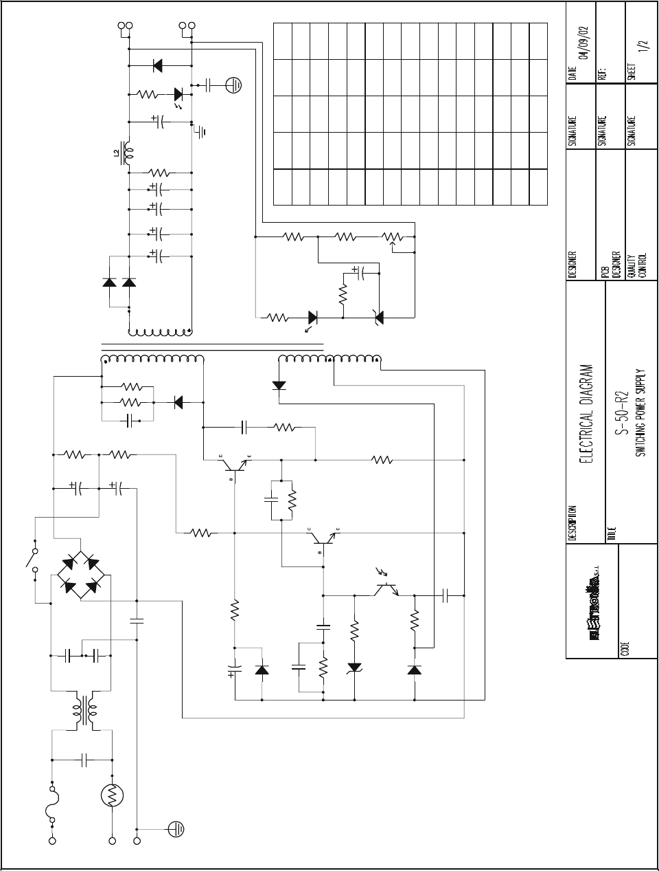
49
D4
1N4148 R12
22
R9
51/2W
C10
D3
1N4001
222/50V
C20
C11
104/50V
ZD1
5V1
3K
R11
R10
470
5
1
3
2
D5
1N4148
C8
221/1KV
R6
82/2W
Q1
2SC3679
C9
154/50V
R7
150
Q2
HIT5609C
R13
75K/1/2W
R8
0.39/2W
U1:2
4N35
C12
473/100V
AC/L
AC/N
FG
FG
RTH1
10SP010
FS1
3A/250V
C1
104/630V
L1
3104C
222/2KV
C2
222/2KV
C3
222/2KV
C7 BD1
4A/800V
SW1
220/110
C4
220u/200V
C5
220u/200V
R3
75K/1/2W
C6
103/1KV
R4 47K/3W
R5 47K/3W
D2
FR157
T1
7
R2
150K/1W
C17
R16
R17
LED1 D8
C16
9,10,11
12,13,14
D6:1
D6:2
C14
C13
C15
+V
GND
-200
BYQ28X
-200
BYQ28X
1000u/16V
XX
RB-003RB-009
470u/35V
470u/35V
470u/35V
FR102FR102
TF-074NTF-060N
1000u/16V
1000u/16V
D8
D6
L2
T1
C17
C16
C13,C14
C15
S15SC4M
TF-059N
X
2200u/16V
2200u/16V
2200u/16V
RB-011
1000u/16V
SVR1
1K
C
R
A
SHR1
TL431
51/2W
0.47u/50V
470
MODEL
S-50 DIFFERENT COMPONENT :
5V
R15
R14
PART NO
1K5
2K
12V 15V
R16
R17
C10
2K1K5
12K7K5
FG
270/2W270/2W
154/50V154/50V
2K72K7
R14
R15
C19
103/1KV
C18
1u/50V
R19
51
4N35
U1:1 R18
100
24V
2K2
22K
680/2W
154/50V
4K7
TF-061N
FR102
RB-003
X
X
470u/35V
470u/35V
BYQ28X
-200

50
COMPONENT LIST S-50-24
SPECIFICATIONS QUANTITY POSITION
BOM FOR S-50N-24 ON CASE 1
CASE 901-D-R1 M 1
CASE 901-T-R2 M 1
HS YS004W-045-R4 71268W-045 1 HS2
MHS002-R1 25mm 1 D6
PR-7.5 1
BOX 901 168x105x45mm 1 1
SCREW F 3x6 ISO NI 2 HS2
SCREW F 3x18 ISO NI 1 HS2
SCREW T 3x6 ISO NI 2 CASE
SCREW P 3x6 ISO NI 1 FG
LABEL S-50-24-R2 1
LABEL IN/OUT UL B017-R1 S-60N 1
LABEL SWITCH C002-R2 110/220 1
CARTON 901 0.97CUFT 1 30
BOM FOR S-50N-24 ON PCB 1
R/C 1/4W 22Ω 5% HP=10 T-52mm 1 R12
R/C 1/4W 51Ω 5% HP=10 T-52mm 1 R19
R/C 1/4W 100Ω 5% HP=10 T-52mm 1 R18
R/C 1/4W 150Ω 5% HP=10 T-52mm 1 R7
R/C 1/4W 470Ω 5% HP=10 T-52mm 1 R10
R/C 1/4W 2.2kΩ 5% HP=10 T-52mm 1 R15
R/C 1/4W 3kΩ 5% HP=10 T-52mm 1 R11
R/C 1/4W 4.7kΩ 5% HP=10 T-52mm 1 R17
R/C 1/4W 22kΩ 5% HP=10 T-52mm 1 R14
R/C 1W 75kΩ 5% CFR-1WS 2 R13, R3
R/C 1W 150kΩ 5% CFR-1WS 1 R2
R/MO 2W 51Ω 5% 1 R9
R/MO 2W 82Ω 5% 1 R6
R/MO 2W 680Ω 5% KINK 1 R16
R/MO 3W 47kΩ 5% MINI KINK 2 R4, R5
R/W 2W 0.39Ω 5% 1 R8
MVR 0.3W 1kΩ 10% HP=5x5 1 SVR1
NTC 3A 10Ω SCK103 KINK 1 RTH1
JUMP 0.6 P=10 2 J3, J4
JUMP 0.6 P=12.5 2 J1, J2
C/M 104/630V 10% P=15 1 C1
C/C 221/1KV 10% P=5 Y5P 1 C8
C/ML 222/100V 5% P=3 1 C20
C/ML 473/100V 5% P=5 1 C12
C/ML 104/100V 5% P=7 1 C11
C/ML 154/100V 5% P=7.5 2 C10, C9
C/C 222/2KV EPOXY 20% P=7.5 Z5U 3 C2, C3, C7

51
SPECIFICATIONS QUANTITY POSITION
C/C 103/1KV EPOXY 20% P=10 Z5U 2 C19, C6
C/E 220u/200V 85°C 22x25 USP 2 C4, C5
C/E 470u/35V 105°C 13x26 TM 3 C13, C14, C17
C/E 1u/50V 105°C 5x11 KM 1 C18
BD 4A/600V GLASS D3SB60 1 BD1
RD 1A/50V 1N4001 T-52mm 1 D3
FRD 1A/100V FR102 T-52mm 1 D8
FRD 1.5A/1KV FR157 T-52mm 1 D2
SFRD BYQ28X-200 10A/200V TO220F 1 D6
HIGH-SPEED DIODE 1N 4148 T-52mm 2 D4, D5
ZD 1/2W 5.1V 2% 5C2 T-52mm 1 ZD1
LED GREEN 204GD-A 1 LED1
BJT 2SC3679 5A/800V TO3P 1 Q1
BJT HIT5609C 1A/20V TO92M 1 Q2
SHR 431 2.5V 2% MM1431AT 1 SHR1
PHOTO 4N35 1 U1
RB-COIL RB003A-R1 6x25 4uH 1 L2
LF 3104C A8222-1 1 L1
MT TF061N EI-40 S-50-24 1 T1
SW 110/220 04-3S6P/SS-22F15-G4 1 SW1
FUSE 3 L 250 5x20 G- 1 FS1
FUSE CLIP 5x20 2 FS1
TB HB951-05P/DT49-B01W-05P 1 TB1
HS HS001-R2 1 HS1
MHS002-R1 25mm 1 Q1
TCBS-5 1
PCB S-50N-R1 CEM-1 1OZ SS M1 1 PCB
SCREW F 3x12 ISO NI 1 Q1
SCREW P 3x6 ISO ZN 2 HS1
52
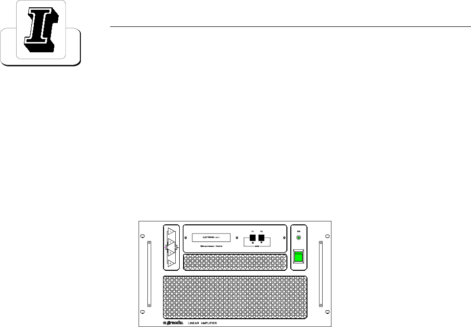
53
LDMOS - UHF TV AMPLIFIER
AUTV/1000LD
User’s manual

54
This page is intentionally blank

55
_______________________________________________________________________________________________
Section 1 - Information
Contents:
1.1 Description
1.2 Technical characteristics
56
1.1 DESCRIPTION
The AUTV/1000LD is an amplifier operating into Band IV-V for common amplification process of the Vision
and Sound carriers.
The amplifier has been designed to offer to the customer high performances, high reliability and greater simplicity
in his operation and maintenance procedures.
The amplifiers modules employ all solid state LDMOS technology in order to obtain high gain, wide-band
performances, very good linearity, reliability and high efficiency.
The equipment design allows the soft degradation (RF power loss) for several transistor faulty: in fact the
output combiner uses RF power resistors for unbalancing power dissipation.
The amplifier is put in a 20U rack just ready for a double driver use. Inside the rack there is also the output
band-pass filter.
AUTV/1000LD
LDMOS - UHF TV AMPLIFIER

57
1.5 TECHNICAL CHARACTERISTICS
RF Frequency range 470 - 860MHz
Output power 1kW peak sync.
Video/Sound power ratio 10/1
Out stage technology Solid State LDMOS
Vision-Sound amplification Common
I.M.D. (-8, -10, -16dB) Better than -54dB
Standards B, G, D, K, I, M, N
Spurious and harmonics level In compliance with CCIR rec.
RF Output impedance 50Ω
RF Output connector EIA 7/8”
GENERAL Power supply 230Vac, ±10%, 50/60Hz
400Vac 3P+N (on request)
Power consumption 3500VA at black level
Power factor > = 0.9
Ambient temperature -5° to +45°C
Relative humidity 20% - 90%
Altitude Up to 2.500 meters
Cooling Forced air
Cabinet Rack 19”-6U
PROTEC. THR.
FWD Power 1200W
REF Power 100W
Temperature 70°C
IDCDRIVER 12A
IDCAMPLIFIER 20A
VDCDRIVER 31V
VDCAMPLIFIER 33V

58
This page is intentionally blank