Elexa Consumer DMGW1 Dome Hub User Manual
Elexa Consumer Products Inc. Dome Hub
User Manual
1
The
Z-Box Sm
ar
t
H
om
e
C
ont
r
ol
l
er
Version
2/
Z-Wave Cert No:
Z
C
10
-
XXXXXXXX
Quick Start
This device is a control center (gateway) for Z-Wave home automation networks. It is used to control different
single devices as well as complete defined scenes and actions combining device functions within the network.
It needs only a few steps to get your Z-box up and running.
1. Power it up by plugging in the external power supply
2. Connect the z-box to your local router using a standard Ethernet cable
3. Use a web browser on your desktop PC or mobile internet device and go to login page .Input the IP
address into the address bar, press ENTER to enter the login page.(IP address:192.168.10.1)
4. Login using the initial local default login (login: admin; password: 123456)
5. Got to setup (upper right corner)
My Settings
, remember your remote access ID and define your remote
password. This password is used for accessing the controller from outside the home. It is shared among all
local users in the home. If you want to protect your login from other users inside the home, change the local
default password.
6. Define your rooms using
Rooms
7. Setup the other users and give them access to the rooms.
8. Installing your smart home devices one by one. Use the dialog
Devices
for this
Hardware
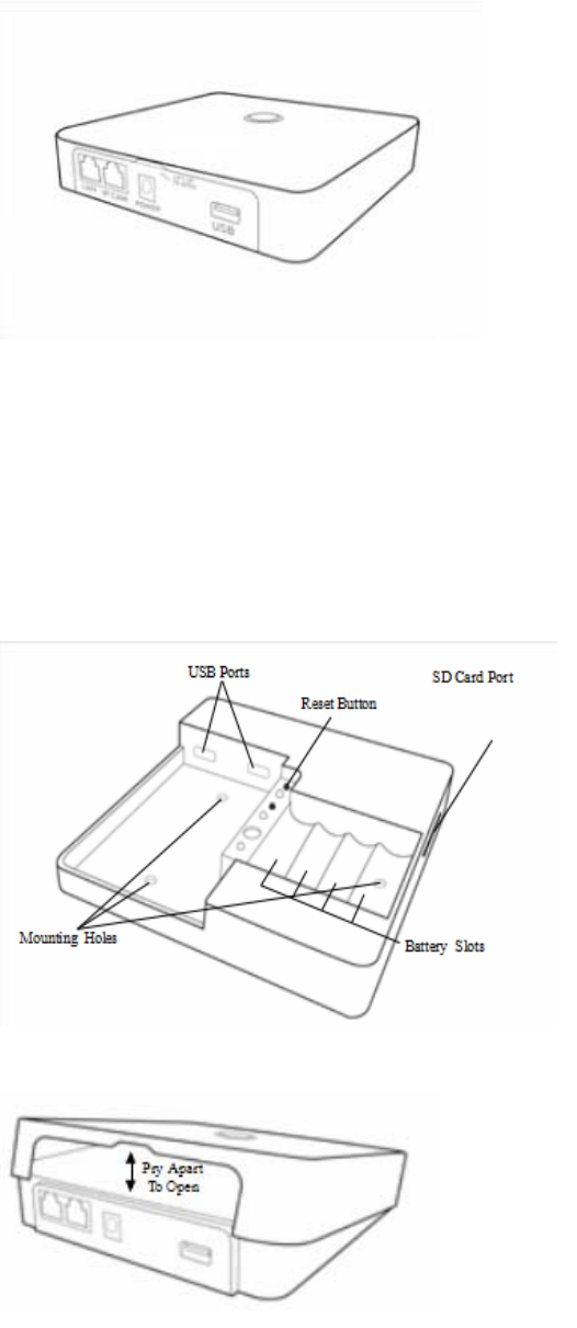
The Z-Box is a small but powerful hardware offering various interfaces:
•Power Input: The device is powered by AC adapter DC9V 1.3A.
•Ethernet: The device can be connected to any standard 10/100 MBit/s Ethernet router
•3*USB(2insidethechamberand1external):The3USBportsallowtoconnectadditionalcommunication
or storage options such as an EnOcean dongle, Bluetooth dongle, hard disk or any other USB device suitable
for Z-box.
Installation
•Connect to Router
Using the LAN cable connect the Z-box to your router.
2
Note-If a connection through the router is not available, there is an refer to the Dome App for step-by-step
instructions when installation is complete.
•Connect to Power
Using the cord provided, connect the Z-box to an electrical wall outlet.
Installing Batteries (optional)
The Z-box uses 4 Ni-MH AA Rechargeable batteries (not included) which allow the system to continue
operation for up to 6 hours (depend on battery capacity and application) when the power is out.
We recommend use 2400mA
Z-Box provide trickle charge to recharge battery which is the safest charging technique, it takes approx. 48
hours to fully recharge 4 x 2400mA Ni-MH rechargeable batteries – please DON’T MIX different
capacity/brand/age of batteries.
To install the batteries, pry open the lid of the Z-box at the notch in the back just above the cable ports.
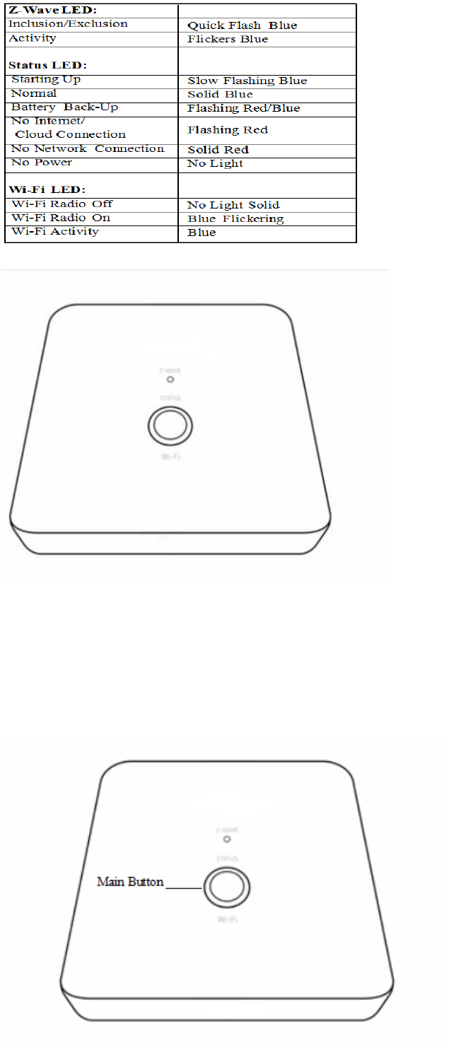
LED Behavior
3
Defaulting Network Settings
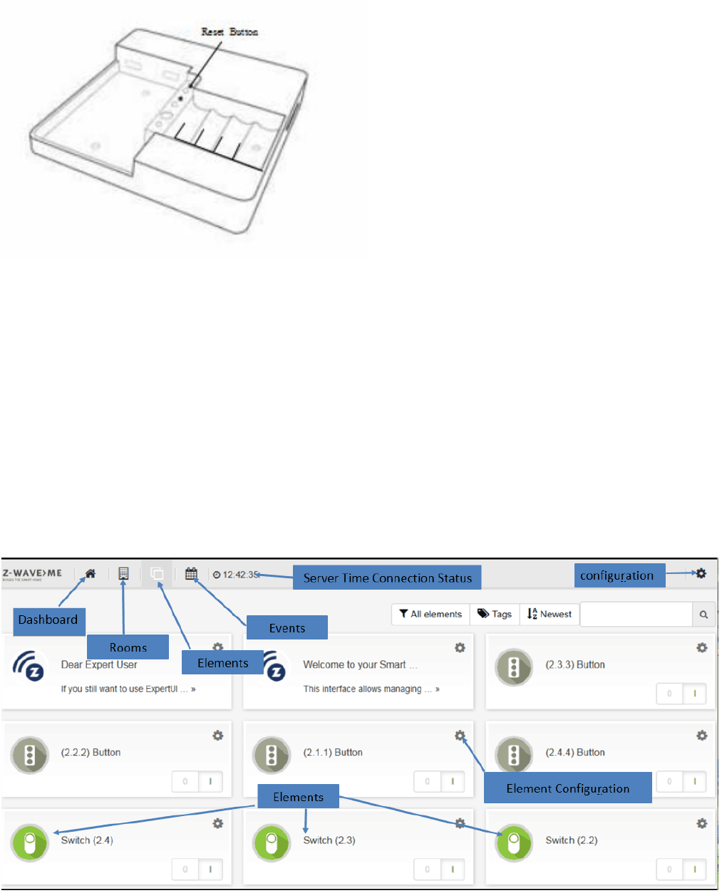
To reset the Network to the default settings, press and hold the Main button (on top of the Z-box) for 10
seconds. Release the button when the LED quickly flashes red indicating reset. Refer to the Dome App to
reconnect the Z-box.
4
Defaulting the Z-box to Factory Settings
Important:
Resetting the Z-box will delete all the settings, disconnect all Z-Wave devices and delete all of the
presets.
To revert to the Factory default settings, press and hold the Reset button (inside the Z-box) for 10 seconds.
Release the button when the Status LED quickly flashes red indicating reset.
Smart Home User Interface
Your smart home can be controlled from different user interface. The design of the interface will adapt to the
various screens of PC, pads or mobile phones.
This interface allows managing your smart home equipped with interconnected Z-Wave devices. It will show
every function of the device as one single Element (In case a physical device has multiple functions – like
switching and metering – it will generate multiple elements). All elements are listed in the Element View and
can be filtered by function type (switch, dimmer, sensor) or other filtering criteria. Important elements can be
placed in the Dashboard. Additionally the elements can be grouped into rooms. Every change of a sensor value
or a switching status is called an event and is shown in the Timeline. Filtering allows monitoring the changes
of one single function or device.
5
Functions of the User Interface
General
Thegreentimeontheheadershowsthetimeofthelastcommunicationtothesmarthomegateway.Incase
communication gets lost, a red sign is shown.
Different users (login/password) have different dashboards and settings. Apps and tags are activated for all
users. Admin privilege is to setup new users, install/configure/delete apps and assigning access rights of
rooms to users
Elements
Clicking into the element may show more control options (like for dimmers or motor control). Switching a
switch will immediately result in showing the new state but in greyed. Once the wireless network reconfirms
the new state of the switch, the new switching status is shown using the real color icon.
The Element Configuration allows assigning user-defined tags to different elements. This allows further
grouping or filtering. It is even possible to use tags inside apps to auto-select certain elements. The time
shown in certain elements refers to the time where value was read from the sensor. You can change this by
configuring the app “Sensor Polling”.
Some physical Z-Wave devices are quite complex generating a lot of functions. You may want to delete
certain elements from the element view. This can be done on the elements configuration with the checkbox
“Permanently delete”. If you accidently deleted an element you need to go to Setup Z-Wave Network, Tab
Network and click on the physical device that generated the very element. Here you can hide/unhide every
element.
Timeline
Some elements may create a lot of events regardless of their possible polling. If you don’t want them to
flood your timeline disable all events from this device using the element‘s configuration dialog. In your
personal settings you can define if new elements shall generate events or not. This setting can be changed
as well.
Devices
You can include all certified Z-Wave devices. If you can’t find your device in the list of known devices please
use the Autodetect function. It will create the same result but you need to find out from the device manual
how to add (include) the device to the network.
To use EnOcean devices a special EnOcean transmitter USB stick needs to be attached to the Z-box.
Furthermore the EnOcean module needs to be activated. Please note that only a selection of EnOcean
devices are supported by the EnOcean module. You can browse through the list of supported EnOcean
devices.

6
Z-Wave Network
This menu option allows a deeper look into the Z-Wave network. The tab
Network
lists all Z-Wave hardware
devices and the elements controlled by them. A configuration button allows changing the names and room
assignment of all element. At the end of this dialog a button
Hardware Configuration
leads to a hardware
specific configuration dialog. Some Z-Wave devices offer such configurations to adapt their functions. Not
having this configuration option is not a malfunction!
The tab
Network Status
lists possible problems of Z-Wave devices and the Z-Wave network. A link refers to
the Z- Way Expert User Interface. Please note that this Expert User Interface is for Z-Wave experts. The
Razberry documentation and user forums will provide help for its use if needed. Direct access to the Z-
Wave Expert User Interface is always possible using http://ip:8083/expert/
My Settings
This menu allows the usual user settings (color, languages, preferences). For users with admin privileges
this dialog also controls the essential access credentials for the remote access using find.z-wave.me.
User Management
This menu item is only available for users with admin privileges.
The Z-Box Z-box is powered by Z-Way, the famous Z-Wave control software of Z-Wave.Me that is also
powering famous projects such as Razberry (razberry.zwave.me: This means that all apps, workarounds,
tricks and How Tos provided and describes for the Razberry project – e.g. on http://forum.z-wave.me/ –
can be used and applied for the Z-box too.
Super
Quick
Start
for Insid
ers
1. 2. Go to
f
i
n
d
.
z
w
a
v
e
.
m
e
,
f
i
n
d
the
IP
address
of your Z-Box, click on
i
t
3.
Setup
your
password
and
remember
your Z-Box
ID
for
f
ut
ur
e
remote
a
cc
es
s
4.
Choose
htt
p
:
//
YO
U
R
PI
_
I
P:
8083 or
use
f
i
n
d.
z
w
a
v
e
.
m
e
for
remote access
to your Smart
H
o
m
e
In
t
e
r
f
a
c
e
.
Quick
Start
for
the
rest
of
us
Z-Box
is a
Z-Wave
c
on
t
r
ol
l
e
r
for your Smart
Home.
A
b
u
il
t
-
in
web server
allows fast
installation and
u
s
a
g
e
without
i
n
s
t
a
lli
n
g
f
u
r
t
h
e
r
s
o
f
t
wa
r
e
or
apps.
Of
course there are
apps
for
v
a
r
i
o
u
sm
o
b
il
e
p
l
a
t
f
o
r
ms
that
can
b
e
down
l
oa
de
d
from
the
v
a
r
i
ou
s
app stores
that
f
u
r
t
h
e
r
enhance the user
e
xp
e
r
i
e
n
ce
of the
s
o
l
ut
i
o
n.
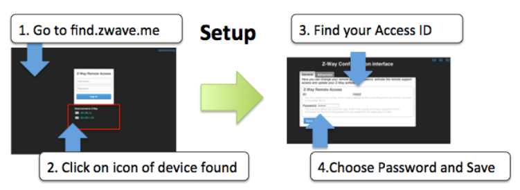
7
Power
it
up. After about
1
m
i
nu
t
e
open
a
w
e
b
br
ow
s
e
r
and point
to
f
i
n
d.
z
w
a
v
e
.
m
e
Below
the
login
screen
you will
see the
IP
address
of your
Z-Box system.
Click on
the
IP
address
link to
o
p
e
n
the
c
o
n
f
i
g
u
ra
ti
o
n
d
i
a
l
o
g
.
The Conf
i
gurat
i
on Ser
v
i
c
e
The
conf
i
g
ur
a
t
i
on
s
er
v
i
c
e
is
a
cc
es
s
i
b
l
e
with any
web browser
on Port
8084. Whenever
you
want to
c
h
a
n
g
e
se
tt
i
n
g
s
this
se
r
v
i
c
e
will
be
at your
se
r
v
i
c
e
and
is
a
v
a
il
a
b
l
e
i
n
d
e
p
e
n
d
e
n
t
of
the Z-Wave
e
n
g
i
n
e
.
Find your Z-Box
ID
and remember
it for
remote access
to your
s
y
s
t
e
m
.
1.
Choose
a
password that
will
be used
to
a
ut
hent
i
c
a
t
e
for the
remote access
in
the
f
u
ture
.
Whenever
y
o
uaccess
your
Z-Box
within your local
network
(
as
the
first
t
i
m
e
)
you
will not
need
a
p
a
ss
w
o
r
d
.
The
C
onf
i
g
ur
a
t
i
on
s
er
v
i
c
e
uses
the
c
l
oud
i
nf
r
a
s
t
r
uc
t
ur
e
on
f
i
nd
.
z
w
a
v
e.
m
e
for the
f
ol
l
ow
i
ng
f
unc
t
i
ons
:
Fi
nd the
I
P
A
dd
r
ess of your
Z-Box.
You just
used
this
f
un
c
t
i
on
.
Remot
e
A
cc
e
s
s
when
you
are
o
u
t
s
i
d
e
your
home.
For this a
v
al
i
d
password
is
r
e
q
u
i
r
e
d
–
see
a
b
o
v
e
.
Fi
r
m
w
a
r
e
U
pd
at
e
:
Just
click on
the firmware
update tab and
follow
the
i
n
s
t
r
u
c
t
i
o
n
s
Remot
e
S
u
ppor
t:This
fu
n
c
t
i
o
n
is usually
d
i
s
a
b
l
e
d
.
Y
o
u
will
need
to
e
n
a
b
l
e
it on
request
if you
d
e
s
i
r
e
remote
s
e
rv
i
c
e
.
Allowing service
p
e
o
p
l
e
to
access
your
Z-Box
is 100%
under
your
co
n
t
r
o
l
.
Once
you
set
your
remote access password
you
are done
with
the
initial
c
o
n
f
i
g
u
r
a
t
i
o
n.
8
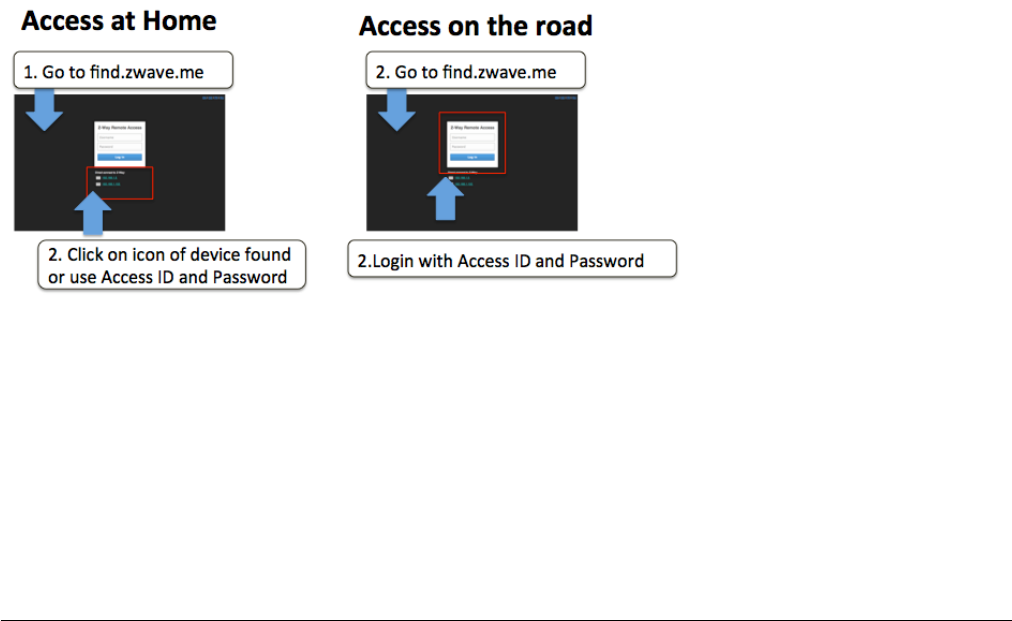
Whenever
you
access
f
i
n
d
.
z
w
av
e
.
m
e
again and
alocal
Z-Box
is
f
o
un
d
clicking
on
the
IP
address
will
lead
y
o
u
right
to your Smart
Home User
I
n
te
rf
a
c
e
.
If your Pi
uses
a
fixed
IP
address
this
address
can
be used
for
direct
IP
access without
u
s
i
n
g
the
f
i
n
d
.
z
wa
v
e
.
m
e
s
e
r
v
i
c
e
.
You can
even
turn off the
c
onnec
t
i
on
to the
f
i
nd
.
z
w
a
v
e.
m
e
se
r
v
i
c
e
but be aware that
you will not
have
any
remote access
c
a
p
a
b
ili
ty
anymore.
Also in
case the
IP
address
o
f
your
Z-Box changes
you
may have
difficulty
to
f
i
n
d
the new address. Hence we recommend
us
i
ng
fi
n
d
.z
w
a
v
e
.m
e
.
The
same
t
i
m
e
we want
y
ou to ha
v
e
100% cont
r
ol of any
cloud service usage
of
y
o
u
r
sy
st
e
m
.
Z
-
Wave
Product
Information
This is a
Z-Wave
s
t
a
t
i
cc
o
n
t
r
o
ll
e
r
.
As a
c
e
r
t
i
f
i
e
d
Z-Wave
Plus
device Z-Box
co
mm
un
i
ca
t
i
n
g
with
all
other Z-Wave
c
e
r
t
i
f
i
e
d
de
v
i
c
e
s
regardless
of
vendor
or
year
of origin
and
it
i
m
p
l
e
m
e
n
t
s
the enhanced
f
unc
t
i
o
ns
of
Z-Wave P
l
u
s
.
This
d
ev
i
c
e
can
communicate
in a
se
c
u
r
ee
n
v
i
r
o
n
m
e
n
t
if
the other device supports the secure
environment too.
If not
t
h
e
co
n
t
r
o
ll
e
r
will fall
back
to
the
n
o
r
m
a
l
co
mm
un
i
ca
t
i
o
n
mode
a
u
t
o
m
at
i
c
al
l
y
.
D
u
r
i
n
g
i
n
c
l
u
s
i
o
n
the use
of
secure environment
ca
n
be suppressed
for
performance reason
if
d
e
s
i
r
e
d
.
In
Z-Wave
all
non-battery powered
de
v
i
c
e
such as
the Z-Box
will act
a
s
routers
for
other
d
e
v
i
c
e
s
to form a
s
o
-
ca
ll
e
d
meshed
n
e
t
w
o
rk.
In
case there
is
more than one controller
in the
network
the
c
o
nt
r
o
ll
er
s
need
to
be kept
synchronous
in
regard
to
t
hei
r
kn
o
w
l
e
dg
e
of
the network.
This is
ca
ll
e
d
Con
t
r
o
ll
e
r
R
ep
li
c
a
t
i
o
n
and the
f
o
ll
o
w
i
n
gp
o
li
c
y
ap
p
li
e
s
:
(a)
in
case there
is a
SIS
in
the network
(
c
h
e
c
k
in
C
o
n
tro
ll
e
r
I
n
f
o
m
e
nu
)
every other
c
o
n
tro
ll
e
rs
will
query the
SIS
for
updates.
(
b
)
I
n
the
rare
case th
a
t
there
is no
SIS
and
this
d
e
v
i
c
e
is
Primary
C
ont
r
ol
l
er
please re-include other
controllers
to
p
e
r
f
o
r
m
a
network
in
f
o
r
m
a
t
io
n
up
d
a
te.
The
d
ev
i
c
e
supports
the
command
c
l
a
ss
es
‘
Sw
i
t
chM
ul
t
il
ev
el
’,
‘
Sw
i
t
c
hB
i
na
r
y
’
and
‘
Ba
s
i
c
’
to
catch events
from
devices u
s
in
g
these command
c
l
a
ss
e
s
to
trigger actions
in
the
c
o
n
tro
ll
e
r.
There
is no
other action
pe
r
f
or
m
e
d
than
c
h
a
n
g
i
n
g
v
a
l
u
e
s
in
th
ede
v
i
c
e
data
obj
e
c
t
s
.
The
d
ev
i
c
e
supports
lifeline
(
a
ss
oc
i
at
i
o
n
group
1, max 3
n
o
d
e
s
)
and
16
channels (simulating
a
generic Multilevel
Sw
it
c
h
)
t
o
di
ff
e
r
e
n
t
i
a
t
e
r
e
c
e
i
v
i
n
g
commands
from
de
v
i
c
e
s
not
able
to
send
modern scene control commands. The
c
h
a
nn
e
l
s
support
t
h
e
same command
c
l
a
sse
s
(
B
a
si
c
,
SwitchBinary, SwitchMultilevel and Scene
A
c
t
i
v
a
t
i
o
n
)
that do
not
p
e
r
f
o
r
m
any
r
e
a
l
a
c
t
i
o
n
b
u
t
allow
command
r
e
c
e
p
t
i
o
n
o
n
l
y
.
9
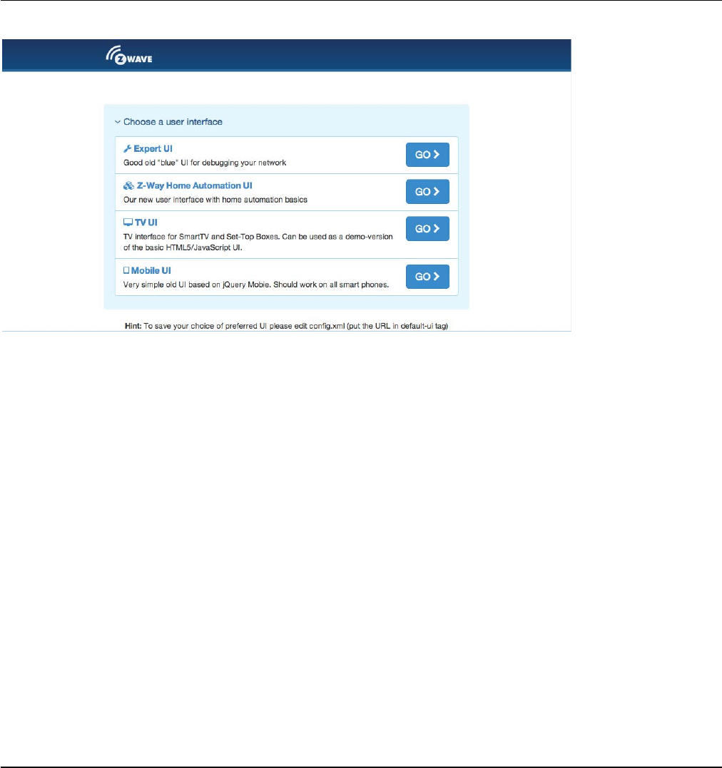
Various
User
Interfaces
of
Z-Box
When going
to
h
ttp
:
//
YO
U
RI
P:
8083
you will
see
a
sel
ec
t
i
on
menu
to
choose
the
web based
UI
you
like
to
w
or
k
with. The two
most
i
nter
es
t
i
ng
UIs
are
the
Z
-
Wa
v
eE
x
p
e
r
t
U
I
(to
create
and
manage
the
Z-Wave
N
e
t
w
o
r
k
)
a
n
d
the
Z
-
Way
H
om
e
A
utomat
i
on user
i
nter
f
a
c
e
for
day-by-day
usage
of
the
wh
o
l
e
system. Above and
b
e
y
o
n
d
this you can
use various m
o
b
il
e
p
l
a
tf
o
rm
na
t
i
v
e
apps
you find in the
app stores
to
access
the
s
y
s
t
em
.
Just visit
the
G
oo
g
l
e
App store
or
the
iOS
app store
for
n
a
t
i
ve
apps
with
the name
“
Z
-
Wa
y
”
.
The
Z
-
Wave
Expert
UI
The Z-Wave Expert User
I
n
t
e
r
f
a
c
e
is
de
s
i
gn
e
d
f
or
i
n
s
ta
ll
e
r
s
,t
e
chn
i
ca
ll
y
s
a
vv
y
p
e
o
p
l
e
and other
us
er
s
that know how to bu
il
tan
d
ma
i
nta
i
na
Z
-
Wa
v
e
based
w
i
r
e
l
e
ss network. Hence
it
uses some
Z-Wave
s
p
e
c
i
f
i
c
language and
offers detailed insight
into
the
work
and data structure
if
the
Z-Wave network.
It allows
to
A
dd
(
in
c
lu
d
e
)
and
remo
v
e
(
e
x
c
l
u
d
e
)
Z
-
Wa
v
e
de
v
i
c
e
s
and manage the
n
e
t
w
o
r
k
.
Con
f
i
g
u
r
e
Z-Wave
de
v
i
c
e
s
.
Op
e
r
at
e
Z-Wave
de
v
i
c
e
s
.
Mana
g
e
Assoc
i
a
t
i
ons
between
w
i
r
e
l
e
ss
de
v
i
c
e
s
.
Ac
c
e
s
sa
l
l
d
ata
g
e
nerat
ed
by
the
de
v
i
c
e
s
and
pe
r
f
or
m
all
k
i
n
d
of
f
un
c
t
i
on
s
and
a
c
t
i
on
s
to
t
h
e
de
v
i
c
e
.
10
Look
b
e
h
i
n
d
th
e
s
cen
e
into
the data structures, routing mechanisms and
timings
of
the
Z
-
Wa
v
e
co
n
t
r
o
l
stack. This is
p
a
r
t
i
cu
l
a
r
l
y
u
s
e
f
u
l
for
d
e
b
u
gg
i
n
g
and
s
o
f
t
w
a
r
e
d
e
ve
l
o
p
m
e
n
t
.
The
Z-Wave Expert
UI
doe
snotprov
i
de
any acc
e
s
stoh
i
gh
e
ror
de
rbu
s
i
n
e
s
s
l
ogi c a n
d
autom at
i
on
.Please
r
e
f
e
r
to
other User
In
t
e
r
f
a
c
e
s
for
these
fu
n
c
t
i
o
n
s
.
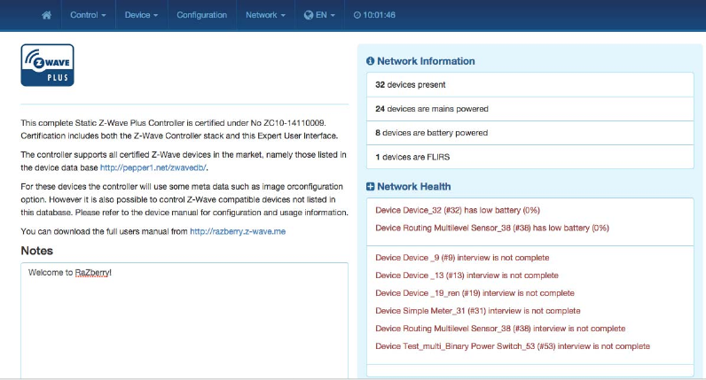
The
UI
offers a
home screen
and four
top menu
i
te
ms
:
Cont
r
o
l
:
Access
to
f
un
c
t
i
o
n
s
of
the
w
i
r
e
l
e
ss
d
e
v
i
c
e
s
i
n
c
l
u
d
e
d
in
the
n
e
t
w
o
r
k
.
De
v
i
c
e
:
Access
to
i
n
f
o
r
m
a
t
i
o
n
about
d
e
v
i
c
e
s
.
Con
f
i
g
u
r
at
i
on:
Con
f
i
g
u
r
e
the
d
e
v
i
c
e
s
a
f
te
r
i
n
c
l
u
s
i
o
n
if
n
ee
d
e
d
.
Net
w
o
r
k
:
Add and remove
d
e
v
i
c
e
s
and manage the
n
e
t
w
o
r
k
.
The
top
level also has a
l
a
ng
ua
g
e
selector.
P
l
e
a
s
e
we aware that
this
s
e
l
e
c
t
i
o
n
is only
v
a
li
d
for
the Expert
UI
a
n
d
will not
be used by other web based
or
app based
U
I
s
.
The
t
i
m
i
ng
info on
the
upper
r
i
g
ht
s
i
d
e
shows
the
t
i
m
e
on
the
c
on
t
r
ol
l
e
r
de
v
i
c
e
.
I
t
s
update serves
as a
heart
beat
to
the
s
y
s
t
e
m
.
All
v
a
l
u
e
s
shown
in
the Z-Wave Expert
UI
are as
s
i
g
n
e
d
to a
t
i
m
e
stamp
i
n
d
i
c
at
i
n
g
when the
value
of
s
t
at
u
s
in
f
o
r
m
a
t
io
n
was
received
from
the wireless network.
A
red
color of
the
t
i
m
e
stamp
i
n
d
i
c
a
t
e
s
that and
u
pd
a
t
e
request
from
the
c
o
n
tro
ll
e
r
for this
v
a
l
u
e
is
p
e
n
d
i
n
g.
Hom
e
S
c
r
ee
n
The
home screen
offers
some high
level
i
nf
or
m
a
t
i
on
about
the
so
f
t
w
a
r
e
and
a
notepad
where the user
o
r
installer
can
leave important
in
f
o
r
m
a
t
io
n
for
f
u
t
u
r
e
u
s
e
.
The
Network
I
nf
or
m
a
t
i
on
box
offers
some
s
t
a
t
i
s
t
i
c
s
about
the
number
of
d
ev
i
c
es
in the
network
and how
m
a
ny
of
them are
mains or
battery operated. The network h
e
a
l
t
hbox
will
list
devices that have problems: the
batt
e
r
y
is
down, the interview
is not
complete
or
the
device
f
a
ile
d
.
Clicking
on
the statement
will
lead
to a
help
p
a
g
e
ex
p
l
a
inin
g
the problems
and giving guidance
for
r
em
ed
i
a
t
i
o
n.
11
Cont
r
ol
The
Control Tab
allows
operating the various types
of
devices and shows the reported values
in
case
of
s
e
n
s
o
r
s
or
meters.
In
case the
c
o
n
t
r
o
l
options
o
ff
e
r
e
d
here are
not
sufficient please
r
e
f
e
r
to
the Expert Command Tab
a
s
part
of
the
C
on
f
i
gu
r
a
t
i
on
menu
for a full
set
of
f
un
c
t
i
on
s
supported
by
the
de
v
i
c
e
.
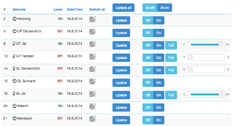
Sw
i
tc
h
The switch
d
i
a
l
og
lists all
d
ev
i
c
es
of the
network
s
up
p
or
t
i
ng
s
w
i
t
c
hi
ng
,
d
i
mm
er
or
motor
control
c
a
p
a
b
ili
t
i
es
.
The
de
v
i
c
e
name and
I
d
and the current status
of
the
switch is
given and
the
t
i
m
e
of
the
last
status update.
T
h
e
“Update” button
f
o
r
c
e
s
an
i
mm
e
d
i
at
e
update
of
the
switch
(if
mains
powered
d
e
v
i
c
e
)
.
A
‘
Sw
i
t
c
h
All’
I
c
o
n
s
h
o
w
s
whether
or not
the
s
p
e
c
i
f
i
c
d
e
v
i
c
e
will
react
on a Switch All ON or Switch All Off
command.
A
green
t
r
i
a
n
g
l
e
indicates that the device
will
react
to
the command
sh
o
w
n.
All actuators can be switched on or off. Dimmer and motors controls can be operated using a slider. For
dimmer there is a button “On” and “Full”. “Full” turns the dimmer always to 100 % diming value while
“On” will turn to the last dimming state before the dimmer was turned off. Clicking on the table heads
reorders the table view of the data.
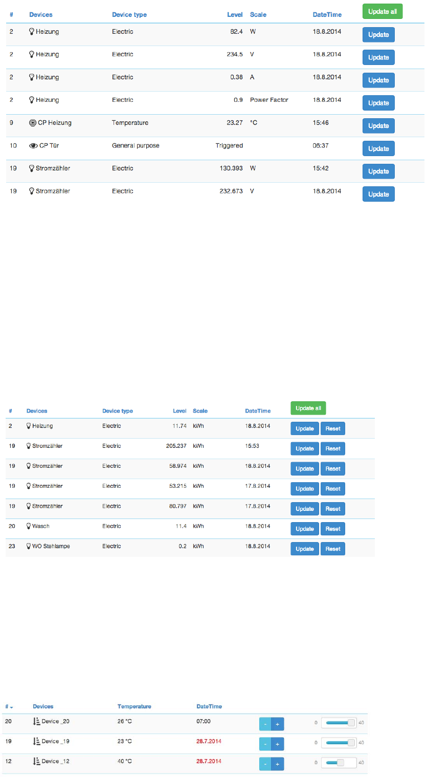
Senso
r
s
The
sensor
d
i
a
l
og
lists all
d
ev
i
c
es
of the
network
p
r
ov
i
d
i
ng
sensor
i
nf
or
m
a
t
i
on.
D
ev
i
c
e
name
and
i
d
,
the
type
of
the sensor, the
a
ct
u
a
l
sensor
va
l
u
e
and the sensor
s
ca
l
e
is
li
s
t
e
d
.
The
D
a
t
e
/
t
i
m
e
co
l
u
m
n
i
n
d
i
ca
t
e
s
when the
g
i
ve
nsensor
v
a
l
u
e
was
r
e
c
e
i
v
e
d
.
I
t
s
p
o
ssi
b
l
e
to call for
a
sensor update but bear
in
m
i
n
d
that battery operated
d
e
v
i
c
e
will only
respond
a
f
t
e
r
the
next
wa
k
e
u
p
.
12
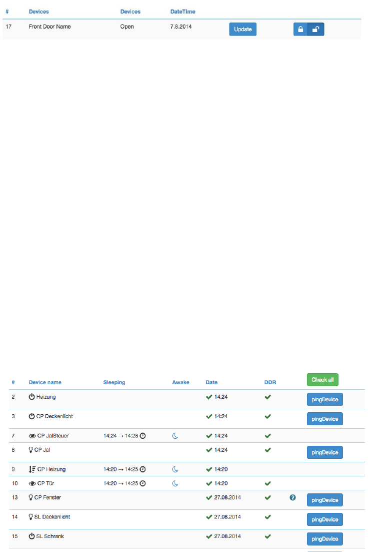
Met
e
r
s
The
meter
d
i
a
l
og
lists all
d
ev
i
c
es
of the
network
p
r
ov
i
d
i
ng
(
a
cc
um
ul
a
t
i
ng
)
meter
i
nf
or
m
a
t
i
on.
D
ev
i
c
e
name
a
nd
id,
the type
of
the meter, the
a
c
t
u
a
l
meter value and the meter
scale is
listed. The Date/time column
in
d
ic
a
t
e
s
when the
g
i
v
e
nsensor
value was
received.
I
t
s
p
o
ss
i
b
l
e
to call for a
meter update but bear
in mind
that
b
a
tt
er
y
operated
de
v
i
c
e
will only
respond
a
f
t
e
r
the next wakeup. Clicking
on
the
t
a
b
l
e
heads reorders the
t
a
b
l
e
view
o
f
the
d
ata
.
Thermostat
s
The
thermostat
d
i
a
l
og
lists all
thermostat devices
of
the network.
D
e
v
i
c
e
name and
i
d
and
the current
set
p
o
i
n
t
temperature
is
shown. The
D
a
t
e
/
t
i
m
e
c
o
l
u
m
n
i
n
d
i
c
a
t
e
s
when the
g
i
v
e
n
set
p
o
i
n
t
temperature
was
transferred
t
othe
d
e
v
i
c
e
.Theset
p
o
i
n
t
temperature
can
be
changed
u
s
i
n
g
the
‘
+
’
or
‘-‘
buttons
or
the slider. Clicking
on
t
h
e
ta
b
l
e
heads reorders
the
t
a
b
l
e
view of the
d
a
t
a
.
13
At
t
e
n
t
i
o
n
:
The temperature
v
a
l
u
e
does
not
d
i
ff
e
r
e
n
t
i
a
t
e
between
h
e
a
t
i
n
g
and
c
oo
li
n
g
d
e
v
i
c
e
s
.
If
a
c
oo
li
n
g
and a hea
t
i
ng
f
unc
t
i
o
n
shall
have
d
i
ff
er
ent set
p
o
i
nt
s
p
l
ea
s
e
refer to the
expert command
s
ec
t
i
o
n
for
more
p
r
ec
i
s
e
command
s
e
tt
i
n
g
s
.
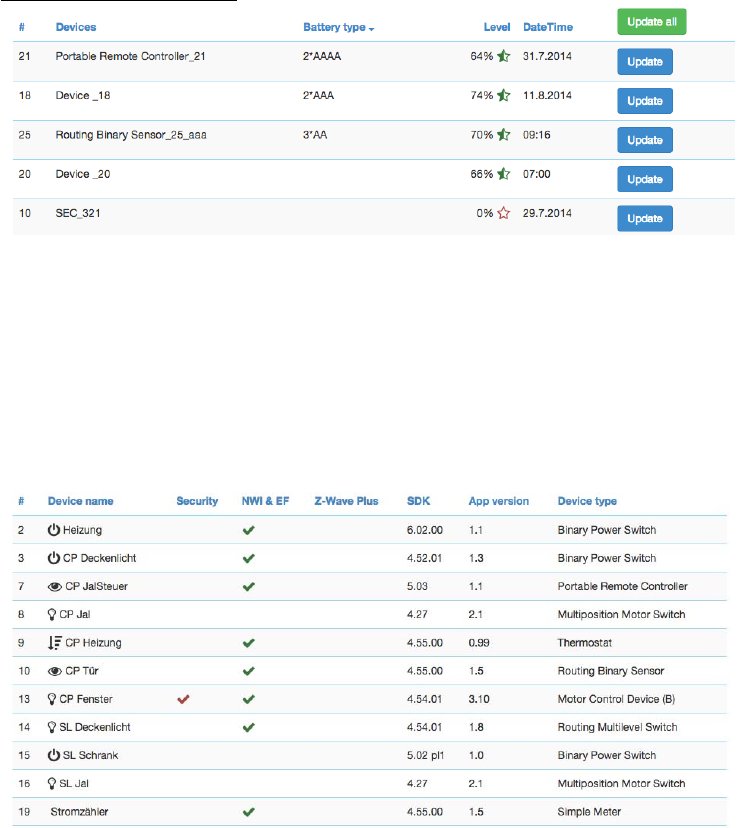
Door
L
oc
k
s
The
door
lock
d
i
a
l
og
lists all
door
lock
d
ev
i
c
es
of the
network.
D
ev
i
c
e
name
and
i
d
,
the
current
status
of the
l
oc
k
and
last
t
i
m
e
of
the change
of
the status
is
lis
t
e
d
.
Clicking
on
the
t
a
b
l
e
heads reorders
the
t
a
b
l
e
view of the
d
a
t
a
.
De
v
i
c
e
The
D
ev
i
c
e
Tab
g
i
v
es
access
to
ov
er
v
i
ew
pages
with
more
det
a
il
ed
i
nf
or
m
a
t
i
on
about
the
d
ev
i
c
es
in the
net
w
or
k
and
t
h
e
i
r
actual s
t
at
u
s
.
Status
:
This
d
i
a
l
og
shows
the
a
c
t
ua
l
network status
of all
d
e
v
i
c
e
s
.
All
devices are listed by their node
id
and name.
T
h
e
dat
e
/
t
i
m
e
i
n
di
c
a
t
e
s
the
t
i
m
e
of
the
last
s
u
cc
e
ss
f
u
l
c
om
m
un
i
c
a
t
i
on
s
between the
c
on
t
r
ol
l
e
r
and
this
de
v
i
c
e
(
e
i
t
h
e
r
co
n
f
i
r
m
e
d
s
e
n
d
i
n
g
or
r
e
ce
p
t
i
o
n
)
.
The green
checkmark indicates that the device
is
alive.
A
red
sign
in
d
ic
a
t
e
s
that
the
c
o
n
tro
ll
e
r
assumes the
d
e
v
i
c
e
not
being
a
c
t
i
v
e
anymore.
Mains
powered
d
e
v
i
c
e
s
can
be checked
fo
r
th
e
i
r
network availability by
h
i
tti
n
g
the “Check
c
o
nn
e
c
ti
v
i
ty
”
b
u
tto
n.
In
case the device interview and
c
o
n
f
ig
u
r
a
t
io
n
was not
p
e
r
f
o
r
m
e
d
properly
a little
question
mark icon will
indicate
this.
Clicking
on
the
q
u
e
s
t
i
o
n
mark will
open
a
window
d
i
s
p
l
a
y
i
n
g
the
d
e
t
a
il
s
of
the
i
n
t
e
r
v
i
e
w
p
r
o
c
e
ss
.
The
correct
l
oa
d
i
ng
of a
D
ev
i
c
e
D
es
c
r
i
p
t
i
on
File
is
i
nd
i
c
a
t
ed
as well. For
b
a
tt
er
y
-
ope
r
a
t
e
d
de
v
i
c
e
the
t
i
m
e
of
t
h
e
last
wakeup, the time
of
the next
wakeup and the current wakeup status
is
shown. Clicking
on
the
t
a
b
l
e
h
e
a
d
s
reorders the
ta
b
l
e
view
of
the data.
Clicking
on
the
t
a
b
l
e
heads reorders the
t
a
b
l
e
view of
the
d
a
t
a
.
14
Batt
e
r
y
This
d
i
a
l
og
g
i
v
es
an
ov
er
v
i
ew
of the
battery status
of the
b
a
tt
er
y
-
ope
r
a
t
e
d
de
v
i
c
e
s
in
the
network.
D
e
v
i
c
e
s
a
r
e
listed by name and
id. The last
reported battery
level
(
0…
100
%)
including update time
is
shown
as
well
as
t
h
e
number and type
of
battery
if
known. The
“
U
pd
a
t
e
”
button
will
request
a
status update
from
the
d
e
v
i
c
e
.
T
h
e
new
status
will
be
a
v
a
il
a
b
l
e
after the next wakeup
of
the
de
v
i
c
e
.
Clicking
on
the table heads reorders the
t
a
bl
e
view
of
the
d
a
t
a
.
Ty
p
e
I
nf
o
The
type
info
d
i
a
l
o
g
lists all
d
e
v
i
c
e
s
of
the network and
i
n
d
i
c
a
te
s
if
they support enhanced
Z-Wave
f
un
c
t
i
o
n
ssuch
as
S
e
c
u
r
i
t
y
and Z-Wave
Plus.
T
h
e
i
r
Z-Wave
p
r
o
t
o
c
o
l
v
e
r
s
i
o
n,
t
h
e
i
r
a
pp
li
c
a
t
i
o
n
v
e
r
s
i
o
n
and
t
h
e
i
r
d
e
v
i
c
e
t
y
p
e
indicator
is
shown
for
in
f
o
r
m
a
t
io
n
purposes too.
Clicking
on
the ta
b
l
e
heads reorders the
ta
b
l
e
view
of
the
d
ata
.
As
s
o
c
i
at
i
o
n
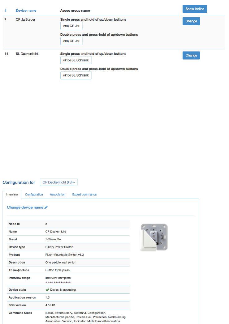
This overview
page
shows the
current association
set in the
network.
The
lifelines
(association
to the
gateway
to
report
status
changes
and
heard
beat)
can be
hidden
if
needed.
A
‚Change’
button
leads right to the
Configuration
page
of the
device
to
change association
settings.
15
Con
f
i
gu
r
at
i
o
n
The Configuration Tab allows configuring the functions of the device. Pick the device to be configured from
the drop down list to access four tabs.
Int
e
r
v
ie
w
The
d
ev
i
c
e
i
nter
v
i
ew s
ec
t
i
on
shows
the
result
of the
d
ev
i
c
e
i
nter
v
i
ew
.
I
n
this
process
the
c
ont
r
ol
l
er
tries to
ge
t
in
f
o
r
m
a
t
io
n
about the device.
In
case the controller find
a
device
description record
for
the
d
e
v
i
ce
it will
d
i
s
p
l
a
y
further
i
n
fo
r
m
a
t
i
o
n
about the
d
e
v
i
c
e
that
can
not
be
obt
a
i
n
e
d
from
the
d
e
v
i
c
e
i
t
s
e
l
f.
If
the
s
o
f
t
w
a
r
e
will
n
o
t
au
t
o
m
at
i
c
al
l
y
r
e
c
o
g
n
i
z
e
the
d
e
v
i
c
e
and
l
o
ad
the
d
e
s
c
r
i
p
t
i
o
n
record
a
button “Choose
D
e
v
i
c
e
D
e
s
c
r
i
p
t
i
o
n
Record”
allows
to do this
m
a
nu
a
lly
.
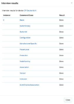
The
i
nter
v
i
ew
stage
line
g
i
v
es
i
nf
or
m
a
t
i
on
about
the
progress
of the
d
ev
i
c
e
i
nter
v
i
ew
by
spl
i
tt
i
n
g
it into
t
h
e
di
ff
e
r
e
n
t
command
c
l
a
ss
e
s
supported
by
the
de
v
i
c
e
.
‘+
’
indicate
a
s
u
cc
e
ss
f
u
li
n
t
e
r
v
i
e
w
,
‘0’
a
permanent
fail
an
d
a
‘
.
’
that this
command
class is still in
the
w
a
i
t
i
n
g
queue
to
be
c
o
mp
l
e
t
e
d
.
There are
a few
reasons
why an
i
nter
v
i
ew
is not
c
om
p
l
et
e:
I
nmostcases
the
d
ev
i
c
es
went to
deep
s
l
eep
t
oo
early to has
some
p
r
o
b
l
em
s
.
The
button “Force
I
nter
v
i
ew
”
allows
re-doing
the whole
i
n
t
e
r
v
ie
w
.
The
b
u
tt
o
n“Request
N
I
F
”
requests
a
Node
I
n
f
o
r
m
at
i
o
n
Frame
from
16
the
d
e
v
i
c
e
and the Button “Show
i
n
t
e
r
v
i
e
wr
e
s
u
l
t
s
”
allows
d
i
s
p
l
ay
i
n
g
the
i
n
f
o
r
m
at
i
o
n
about
the
d
i
ff
e
r
e
n
t
command
c
l
as
s
e
s
f
o
un
dd
u
r
i
n
g
the
i
n
t
e
r
v
i
e
w
.
I
t
is
al
s
opos
s
i
bl
e
to
f
or
c
e
the
i
n
t
e
r
vi
e
w
of a
ce
r
t
a
i
ncommand
class
on
l
y
.
The only
conf
i
g
ur
a
t
i
on
opt
i
on
on this
tab
is to
change
the
g
i
v
en
name
of the
d
ev
i
c
e.
During
i
nc
l
us
i
on
t
he
so
f
t
w
a
r
e
generated
a
g
e
n
e
r
i
c
name but
it is
h
i
g
h
l
y
recommended
to
change
this
name. The
g
i
v
e
n
name
sh
o
u
ld
be
de
s
c
r
i
pt
i
v
e
bit not too
l
on
g.
Con
f
i
g
u
r
at
i
o
n
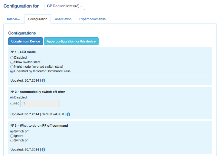
The
conf
i
g
ur
a
t
i
on
tab
allows
conf
i
g
ur
i
ng
the
d
ev
i
c
e.
There are
four
more command
c
l
a
ss
es
that
may
need
a
dd
i
t
i
ona
l
conf
i
g
ur
a
t
i
on
work
and that
are displayed
if
th
e
ce
r
t
a
i
ndevicesupports
it.
The
a
c
t
u
a
l
data
of
the
di
ff
e
r
e
n
t
s
e
c
t
i
on
s
are
shown
in
the
UI
and
can
be
u
pdat
e
d
using the
button
“
U
pd
a
t
e
from
d
ev
i
c
e”
A
t
i
m
e
i
nd
i
c
a
t
i
o
n
shows
when the
t
i
m
e
where
the
v
a
l
ues
where
r
ec
ei
v
ed
from
the
d
e
v
i
c
e
(
B
e
w
a
r
e
,
that
an
update
may
be d
e
l
a
y
e
d
if
the
d
e
v
i
c
e
if
battery operated
an in
deep
s
l
ee
p
s
ta
te
)
•
Wa
k
e
u
p
:
D
ef
i
ne
the
wakeup
i
n
t
e
r
v
a
l
and the node
is of
the
main
c
on
t
r
ol
l
e
r
t
a
k
i
n
g
care
of
the
w
a
k
e
u
p
sequence. The
c
o
n
t
r
o
ll
e
r
will set a
standard wakeup
t
i
m
e
of 1800
seconds
un
l
e
ss
the
d
e
v
i
c
e
s
sets
a
di
ff
e
r
e
n
t
minimal or
ma
x
i
ma
l
wakeup
t
i
me
.
I
n
most
cases the node
i
d
of
the
c
on
t
r
ol
l
e
r
is
the
c
or
r
e
c
t
se
tt
i
n
g
for
the target node
i
d
and
sh
o
u
l
d
not
be changed.
In
case
this
c
o
n
t
r
o
ll
e
r
is only
se
c
o
n
d
a
r
y
co
n
t
r
o
ll
e
r
this
v
a
l
u
e
may
change.
A tool
t
i
p
on
the
i
n
p
u
t
f
i
e
l
d
shows the
a
l
lo
w
e
d
minimum and m
a
x
im
u
m
wakeup
t
i
m
e
as
reported by the
d
e
v
i
c
e
.
•
Pr
otect
i
on:In
case the device supports
local
protection
–
means suppressing
local
use
of
the device –
the
b
e
h
a
v
i
o
r
of this
f
un
c
ti
o
n
can
be d
e
f
i
n
e
d
.
The
p
r
o
t
e
c
t
i
o
ncommand
class
ac
t
u
al
l
y
offers more
opt
i
on
s
than displayed here, Refer
to
the
‘
E
x
p
e
rt
Co
mm
a
n
d
s
’
tab
for a
c
o
m
p
l
e
t
e
set
of
c
o
n
t
r
o
l
s
.
•
Sw
i
tch
A
l
lco
nf
i
g
urat
i
on:
Z-Wave supports the
so
c
a
ll
e
d
switch all
f
un
c
t
i
o
n
as a
broadcast
to
a
ll
sw
i
t
c
h
e
s
and
d
i
mm
e
r
s.
This
setup
d
e
f
i
n
e
s
the
r
e
a
c
t
i
o
n
of
the
de
v
i
c
e
to such a “Switch All”
c
om
m
a
n
d.
The
s
et
t
i
ng
is also
d
i
s
p
l
a
y
ed
in the
“
Sw
i
t
c
hes
“
s
ec
t
i
on
as
li
tt
l
e
gray/green
i
c
on.
•
Con
f
i
g
u
r
at
i
on :In
case the controller
can
identify the device and finds
in
f
o
r
m
a
t
io
n
about
f
u
r
t
h
e
r
co
n
f
i
g
u
r
a
t
i
o
n
o
p
t
i
o
n
s
these
opt
i
on
s
are shown.
The
li
tt
l
e
(i)
symbol
may
g
i
v
e
more
d
es
c
r
i
p
t
i
v
e
in
f
o
r
m
a
t
io
n
about the
c
o
n
f
ig
u
r
a
t
io
n
value.
If no
device
description
of
the device
is
f
o
un
d
n
o
co
nf
i
g
ur
a
t
i
o
n
o
p
t
i
o
ns
are shown.
I
n
case
the
d
ev
i
c
e
does have
c
o
nf
i
g
ur
a
t
i
o
n
o
p
t
i
o
ns
its
p
o
ss
i
b
le
to
s
e
t
them
u
s
i
n
g
the expert
command
s
e
c
ti
o
n.
17
Note:
For mains
powered
d
e
v
i
c
e
s
and
FLIRS
d
e
v
i
c
e
the button
“
A
pp
l
y
c
o
n
f
i
g
u
r
a
t
i
o
n
to
d
e
v
i
c
e
”
will
a
c
t
i
v
a
t
e
t
h
e
changes
within
few seconds.
For
battery operated devices the commands
are stored
to
the next wakeup.
I
t
s
pos
s
i
bl
e
and recommended
to
wakeup the
de
v
i
c
e
m
a
nu
a
ll
y
to
speed up the change
of
c
on
f
i
gu
r
a
t
i
on
v
a
l
u
e
s
.
As
s
oc
i
at
i
o
n
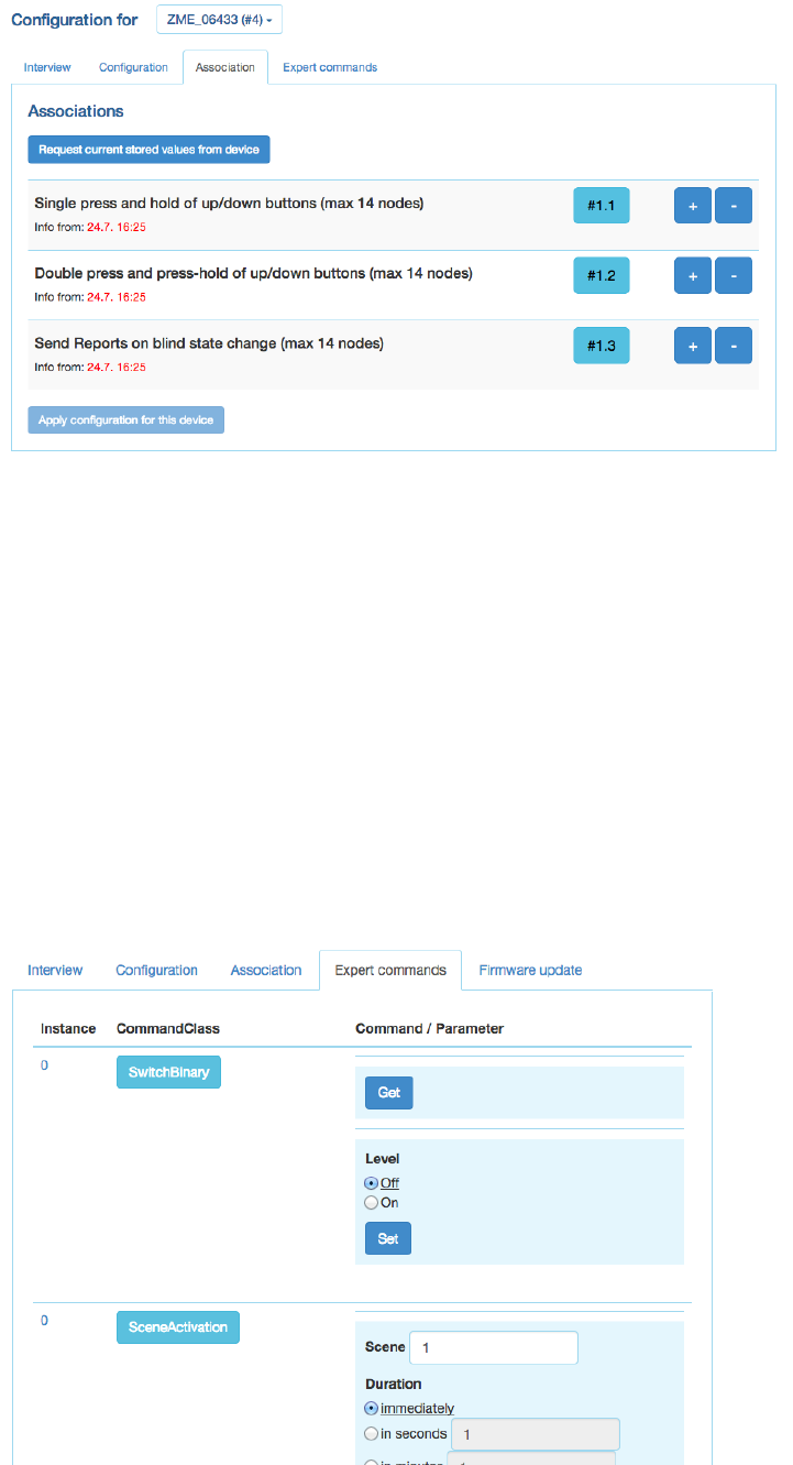
Associations allow switching a Z-Wave device B (target) as a result of an event in Z-Wave device
A (source). Z- Wave device A offers lists of devices to switches for each event supported. The
list of these events - also called association groups - and the devices that are associated with
it are shown in the Association tab. In case the information is provided either by the device or
by the device record stored in the software the meaning of the events is written. Otherwise only
event group is shown unnamed. In this case refer to the devices manual for more information
about the association group meaning. The stored devices can be called from the actual device
using a button. The buttons ’+/-’ used to add and remove device from the group. A dialog is
opened and a device can be picked. In case this device has multiple instances an instance drop
down list will appear allowing
to choose the right instance of the target device. The node ID and - if applicable – the instance
id are shown in
the target device list. Move the mouse over the ID to show the complete given name of this
device.
18
Ex
pe
r
t
C
om
m
a
n
ds
The
expert command
s
ec
t
i
on
displays the status
v
a
l
u
e
s
and
pos
s
i
bl
e
commands
in a
very
ge
n
e
r
i
c
way. On
t
h
e
left
hand side the
d
iff
e
r
e
n
t
channels
of
the device are listed
in a
column.
In
case there
is only
one
c
h
a
nn
e
l
(t
h
a
t
’s
the case
for
most
d
e
v
i
c
e
s
)
only
c
h
a
nn
e
l
0is
shown.
Clicking
on
the number opens
a
d
i
a
l
o
g
s
h
o
w
i
n
g
all
i
n
t
e
r
n
a
l
va
r
i
a
b
l
e
s
for
the
ch
a
nn
e
l
.
The
next
co
l
u
m
n
shows
all
the command classes exposed by the device.
A
g
a
i
n
cl
i
cki
n
g
on
the
name opens
a
di
a
l
og
with
more
i
n
t
e
r
n
a
l
status
v
a
r
i
a
bl
e
i
n
f
or
m
a
t
i
on
for this
command
c
l
a
ss
.
On
the
r
i
g
h
t
hand
s
i
d
e
there
is a list of
commands.
This
UI
is
auto-generated
from
the
i
n
f
or
m
a
t
i
on
pr
ov
i
de
d
by
the command
class
i
ts
e
l
f
and
not
o
p
ti
m
i
z
e
d
for
d
a
il
y
usage.
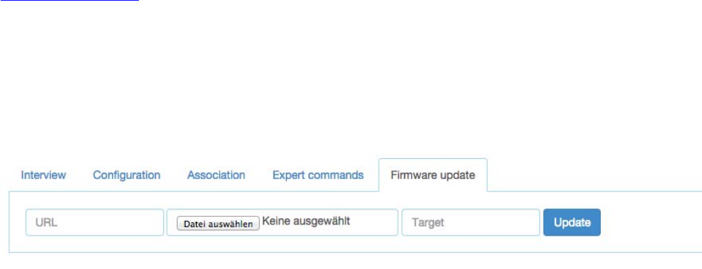
19
Fi
r
m
w
a
r
e
U
pd
at
e
In
case the device supports
a
firmware
update ‘over the
ai
r
’
this
d
i
al
o
g
is
shown
to
p
e
r
f
o
r
m
such a
f
i
r
m
w
ar
e
update.
The firmware
can
be p
r
o
v
i
d
e
d
in two ways:
either
as
URL
in
the
f
o
r
m
a
t
ht
t
p
:
//
I
P:
PO
R
T/
f
il
e
or as
f
il
e
up
l
oa
d
using the
f
il
e
up
l
oa
dd
i
a
l
o
g
.
The firmware
f
il
e
must
be
a
v
a
il
a
b
l
e
in raw
‘BIN’
f
o
rm
a
t
or
‘HEX’
f
or
m
a
t
.
T
h
e
target
f
i
e
l
d
allows
s
p
e
c
i
f
y
i
n
g
the target
memory/processor
for
the update process.
For
updating the
Z
-
Wa
v
e
firmware part
a
‘0’
must
be set. The firmware
u
pd
a
t
i
n
g
process
will
take up
to 10
m
i
nu
t
e
s
.
Please don’t do
a
ny
other
ope
r
a
t
i
on
du
r
i
n
g
this
t
i
m
e
.
It may
be
r
e
q
u
ir
e
d
to
activate the firmware
update mode
on
the device
to
be updated.
Please
r
e
f
e
r
to
t
h
e
manu
a
l
for
f
u
r
t
h
e
r
i
n
f
o
r
ma
t
i
o
n
about
a
c
t
i
v
a
t
i
o
n.
Net
w
o
r
k
The
Network
s
ec
t
i
on
of the
UI
f
oc
us
e
s
on
the network
as such
and offers
all
c
o
n
t
r
o
l
s
and
i
n
f
o
r
m
a
t
i
o
n
to
b
u
il
d
,
manage and
r
e
p
a
i
r
the
w
i
r
e
l
e
ss
network
of
the
c
o
n
t
r
o
ll
e
r
.
Cont
r
ol
The
network control summ
a
r
i
z
es
all
commands needed
to
manage
the
network
and the
c
ont
r
ol
l
er
.
The
page
is
structured
in four
box
e
s
.
The
d
ev
i
c
e
management
box allows
i
n
c
l
u
d
i
n
g
and
e
x
c
l
u
d
i
n
g
Z-Wave
d
e
v
i
c
e
s
.
A
status
d
i
s
p
l
a
y
shows the
s
t
a
t
u
s
of the
c
on
t
r
ol
l
e
r
.
The
“
I
n
c
l
u
de
D
e
v
i
c
e
”
resp.
“
Ex
c
l
u
de
D
e
v
i
c
e
”
button
turn
the
c
on
t
r
ol
l
e
r
into
the
I
nc
l
us
i
o
n
re
s
p
.
Ex
c
l
u
s
i
on
mode.
In this
case the status display changes
and the resp. buttons
turns into a
“Stop”
f
un
c
t
io
n.
T
h
e
inclusion and exclusion modes
will
time
out
a
f
t
e
r
about
20
seconds but
can always
be
t
e
r
m
i
n
a
t
e
d
u
s
i
n
g
t
h
e
“Stop”
b
u
tt
o
n
s
.
Another
way to
stop the
i
n
c
l
u
s
i
o
n
mode
is t o a c t u a
ll
y
i
nc
l
u
de
an
e
w
d
e
v
i
c
e
.Inthis
case
the
i
n
c
l
u
s
i
o
n
m
o
d
e
will
stop and the node
i
d
of
the new
de
v
i
c
e
is
shown. The
c
on
t
r
ol
l
e
r
generated
a
de
f
a
u
l
t
name
of
the
de
v
i
c
e
a
s
co
m
b
i
n
a
t
i
o
n
of its
p
r
i
mar
y
f
un
c
t
i
o
n
and the new
node
i
d
.
Clicking
on this
de
f
a
u
l
t
name
l
e
a
ds
to
t
h
e
Con
f
i
g
u
r
a
t
i
o
n
page where the name
can
be changed
and
other
c
o
nf
i
g
ur
a
t
i
o
n
tasks can
be
p
e
r
f
o
r
m
e
d
.
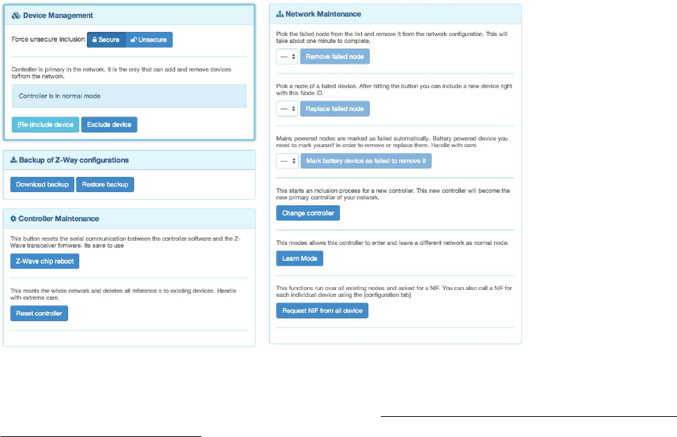
20
Please
refer to the
d
ev
i
c
es m
a
nua
l
on how to do an
inclusion.
In
case the inclusion does
not
work as
e
x
p
e
c
t
e
d
,
please
e
xc
l
u
de
the
d
ev
i
c
e
first. Mo
r
e
than 90 % of all
i
n
c
l
u
s
i
o
n
p
r
o
b
l
e
m
s
a
r
e
caused by
still
i
n
c
l
u
d
e
d
in
a
di
ff
e
r
e
n
t
network and
can
then
not
be
i
n
g
i
n
c
l
u
de
d
a
ga
i
n.
The Ex c
l
u
s
i
on
mode
also
stops when one
d
e
v
i
c
e
was
s
u
cc
e
ss
f
u
ll
y
e
x
c
l
u
d
e
d
.
This
f
un
c
t
i
o
n
can
e
x
c
l
u
d
e
d
e
v
i
c
e
s
from
other networks
too
but the device need be
avai
l
ab
l
e
and
f
un
c
t
i
o
n
i
n
g
.
To
remove
non
f
un
c
t
i
o
n
i
n
g
o
r
disappeared
de
v
i
c
e
s
please
r
e
f
e
r
to
“Replace
F
a
il
e
d
node”
or
Remove
F
a
il
e
d
n
ode
”
.
In
case the new device supports enhanced security
f
un
c
t
io
n
(Security Command
C
l
a
ss
)
this
co
n
t
r
o
ll
e
r
will
i
n
cl
u
d
e
the
d
e
v
i
c
e
s
e
c
u
re
l
y
.
After
this all
data exchange between the
c
o
n
tro
ll
e
r
and the new
d
e
v
i
c
e
is
encrypted
u
s
i
n
g
AES
e
n
c
r
y
p
t
i
o
n.
For
p
e
r
f
o
r
m
a
n
c
e
reasons
it mays
be
d
e
s
i
r
e
d
not to
use the
s
e
c
u
r
i
t
y
f
un
c
t
i
o
n.
The
s
l
id
e
r
“
F
o
r
c
e
unsecure
i
nc
l
us
i
o
n”
turns the
c
o
nt
r
o
ll
er
into a
mode where
all
s
ec
ur
i
t
y
f
unc
t
i
o
ns
are suppressed
for
the
i
n
c
l
u
d
e
d
de
v
i
c
e
.
S
e
c
u
r
i
t
y
f
un
c
t
i
on
s
of
other
de
v
i
c
e
s
are
not
i
m
pa
c
t
e
d
.
The
second
box of
the page
allows cr
e
at
i
n
g
an
d
u
s
i
n
g
a
b
acku
p
.
The backup
f
il
e
is
stored
on
the
l
oc
a
l
computer.
P
l
e
a
s
e
note that
any
restore
will
o
v
er
wr
i
t
e
the
ex
i
s
t
i
ng
network.
The
restore
op
er
a
t
i
on
must
t
her
ef
or
e
be
c
on
f
i
r
m
e
d
in
another message
box. A
checkbox
de
f
i
n
e
s
if
the node
i
n
f
or
m
a
t
i
on
in
the z-wave
c
h
i
p
i
t
s
e
l
f
s
ha
ll
be
ov
e
rwr
i
tt
e
n
as
well.
This
ope
r
a
t
i
on
r
e
s
u
l
t
in a
pos
s
i
bl
e
loss of all
network
r
e
l
a
t
i
on
s
h
i
ps and
may
r
e
qu
i
r
e
a
r
e
-
inclusion
of
devices.
Handle
with
c
a
r
e
.
The
c
ont
r
ol
l
er
m
a
i
nt
ena
nc
e
offers two
reset buttons.
The “Z
-
Wa
v
e
Ch
i
p
R
e
b
oot”
restarts
the
o
p
e
r
at
i
n
g
system
of
the Z-Wave
t
r
a
n
s
c
e
i
v
e
r
c
h
i
p
.
This can
be done
s
a
f
e
l
y
all
the
t
i
m
e
.
The “Re
s
e
tCont
r
ol
l
e
r
”turns
the
c
o
n
t
r
o
ll
e
r
back
into
factory reset.
All
c
o
nn
e
c
t
i
o
n
s
to
i
n
c
l
u
d
e
d
d
e
v
i
c
e
s
and
al
l
co
n
f
i
g
u
r
a
t
i
o
n
s
and
s
e
tt
i
n
g
s
are
lost. This
f
un
ct
i
o
n
must
be
ha
nd
l
es
with
extreme case.
An
a
dd
i
t
i
o
na
l
d
i
a
l
o
g
re
q
u
i
re
s
to
explicitly
confirm
the
f
un
c
ti
o
n.
On
l
yu
s
e
th
i
s
f
unct
i
on
i
f
y
ou
k
now
w
hat
y
ou
d
o!
21
The
f
unc
t
i
on
Remov
e
F
a
il
e
d
N
ode
allows
r
e
m
o
v
i
n
g
a
node
that is not
l
o
n
g
e
r
c
o
mm
un
i
c
at
i
n
g
with
t
h
e
co
n
t
r
o
ll
e
r
.
After
m
u
l
ti
p
l
e
f
a
il
e
d
c
o
mm
un
i
c
a
ti
o
n
s
with a
d
e
v
i
c
e
the
c
o
n
tro
ll
e
r
will
mark this
d
e
v
i
c
e
as
f
a
il
e
d
a
n
d
av
o
i
d
f
u
r
t
h
e
r
c
o
mm
un
i
c
at
i
o
n.
This
f
un
c
t
i
o
n
finally
removes
such a
d
e
v
i
c
e
from
the network
c
o
n
f
i
g
u
r
at
i
o
n.
T
h
e
drop down
list will only show
I
D
s
of
f
a
il
e
d
nodes.
If
this list is
empty
this is a
good
si
g
n
!
It is also
p
o
ssi
b
l
e
to
R
ep
l
ac
e
aFa
il
ed
no
d
e
with a
new node.
This is a
c
o
m
b
i
n
a
t
i
o
n
of
r
e
m
o
v
i
n
g
the
f
a
il
e
d
node
and
a
dd
i
ng
anew
node.
Using this
f
unc
t
i
o
n
makes sure
the next
i
nc
l
ud
ed
node
has the
same node
ID
as
the
f
a
il
e
d
node.
The
drop down
list will only show
I
D
s
of
f
a
il
ed
nodes.
If
this list is
empty
this is a
good
s
i
g
n!

22
Battery operated
de
v
i
c
e
s
are
mainly in
deep-sleep state and
will not
answer
to
c
o
mm
un
i
c
a
t
i
o
n
requests.
H
e
n
c
e
the
c
o
n
tro
ll
e
r
will
never
a
ut
o
m
a
t
i
c
a
ll
y
detect
if a
c
er
t
a
i
n
d
ev
i
c
e
is
defect
or
gone.
The
f
unc
t
i
o
n
“Ma
r
k
b
att
e
r
y
de
v
i
c
e
as
f
a
il
e
d
”
m
an
u
al
l
y
marks
b
at
t
e
r
y
-
ope
r
a
t
e
d
de
v
i
c
e
s
as
f
a
il
e
d
so
that they
can
be removed
or
r
e
pl
a
c
e
s
.
The
dropdown
list
shows
all
battery operated
d
ev
i
c
es
but
this
does
not
mean that they are
f
a
il
e
d.
The next two
f
unc
t
i
ons
d
ea
l
with the
c
ont
r
ol
l
er
role
in the
network.
With ”Learn”this
c
o
n
t
r
o
ll
e
r
can
become a
secondary
c
o
n
t
r
o
ll
e
r
in
another network.
This is only
p
o
ssi
b
l
e
if this
c
o
n
t
r
o
ll
e
r
d
i
d
not
i
n
c
l
u
d
e
any
other
de
v
i
c
e
be
f
or
e
.
Clicking the
“
L
e
a
r
n
”
button
turns
the
c
on
t
r
ol
l
e
r
in a
f
un
c
t
i
on
where
it will
accept
i
n
c
l
u
s
i
on requests
f
r
om other
c
on
t
r
ol
l
e
r
s
.
The
c
on
t
r
ol
l
e
r
status
di
a
l
og
on
the upper
l
e
f
t
hand
s
i
de
shows
this
status. The
L
e
a
r
n
mode
will
time
out
a
f
te
r
about
20
seconds
or
when the
de
v
i
c
e
was
i
n
c
l
u
de
d
s
u
cc
e
ss
f
u
ll
y
.
I
t
is also
pos
s
i
bl
e
to
m
a
nu
a
ll
y
te
rm
i
n
a
te
the
m
o
d
e
.
The “Chan
g
e
Cont
r
o
ll
e
r
”
f
un
c
t
i
o
n
ac
t
i
v
e
l
y
hands over the
r
o
l
e
of
the
p
r
i
mar
y
c
o
n
t
r
o
ll
e
r
of
the
network
to
a
co
n
t
r
o
ll
e
r
that
will
be
i
n
cl
u
d
e
d
using the
no
r
m
a
li
nc
l
us
i
o
n
process.
The
c
o
nt
r
o
ll
er status
d
i
a
l
o
g
shows
the
m
o
d
e
and
its
t
e
r
m
i
n
at
i
o
n.
The “Requ
e
s
tN
I
F
f
r
om a
l
l
de
v
i
c
e
s
”
f
un
c
t
i
o
n
is just a
c
o
n
v
e
n
i
e
n
t
way to
r
e
t
r
i
e
v
e
a
Node
I
n
f
o
r
m
at
i
o
n
Fr
am
e
from all
d
e
v
i
c
e
s
of
the
n
e
t
w
o
r
k
.
The
f
r
eq
uenc
y
change buttons
allow
ch
a
n
g
i
n
g
the o
p
e
r
a
t
i
n
g
f
r
e
q
u
e
n
cy
of
Z-Box. Ha
n
d
l
e
with
c
a
r
e
!
Ch
a
n
g
i
n
g
the
f
re
q
u
e
n
c
y
may
re
s
u
l
t
in
m
a
l
f
un
c
ti
o
n
of your
network.
If you
are
un
c
e
r
t
a
i
n
about the consequences
of
t
h
i
s
change,
d
o
n
’
t
touch the
b
u
tt
o
n
s
!
The Z-Box
hardware
can
be changed
into every
v
a
li
d
f
r
eq
uenc
y
however the antenna
filter used
with
Z
-
Wa
v
e
tran
s
c
e
i
v
e
rs
will
attenuate the
w
i
re
l
e
ss s
i
g
n
a
l
for
wrong
fr
e
q
u
e
n
c
i
e
s
.
At
the
moment there are three
d
i
ffe
r
e
n
t
types
of
antenna
filters
a
ll
o
w
i
n
g
operation
in
the three
f
re
q
u
e
n
c
y
groups.
C
h
a
n
g
i
n
g
the
f
re
q
u
e
n
c
y
within
the
li
n
e
(e.g. from EU to
C
N
)
will not
result
in
attenuation
of
the
signal
but
will
stop
any
communication
in a
n
e
t
w
o
r
k
already
e
s
tab
li
s
h
e
d
.
C
h
an
g
i
n
g
between the
li
n
e
s
will not only
r
e
s
u
l
t
in
c
o
mm
un
i
c
a
ti
o
n
p
ro
b
l
e
ms
with
e
x
i
s
ti
n
g
included devices but
also
result
is
severe attenuation
of
the wireless signal.
It may still
be
u
s
e
f
u
l
to
c
h
a
n
g
e
fr
e
q
u
e
n
c
i
e
s
for
d
e
b
u
gg
i
n
g
purposes but
a
g
a
i
n
:H
a
n
d
l
e
with
c
a
r
e
!
Rout
i
n
g
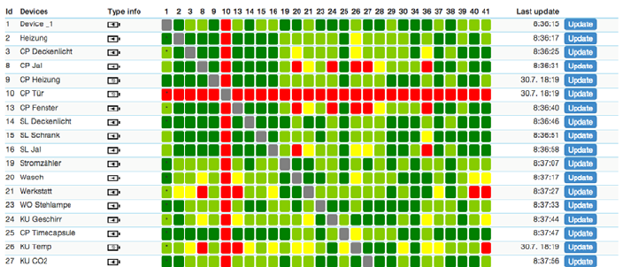
23
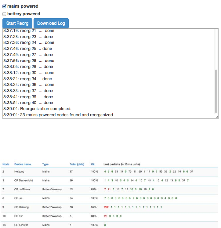
24
This
t
a
b
l
e
shows
the
neighborhood
r
el
a
ti
o
n
s
h
i
p
of
d
e
v
i
c
e
s
.
The
i
d
,
the
name
and the
type
of the
node are
li
s
t
ed
.
Dark
green indicates
that
the
two
d
e
v
i
c
e
s
are in
d
i
re
c
t
w
i
re
l
e
ss
n
e
i
g
h
b
o
rh
oo
d
s
and
d
o
n
’
tneed
any
other
d
e
v
i
c
e
to forward
th
e
i
r
s
i
g
n
a
l
s
.
A
Li
g
h
t
green
co
nn
e
ct
i
o
n
needs one router between.
Y
e
ll
o
w
color
i
n
d
i
c
a
te
s
that
th
e
co
mm
un
i
ca
t
i
o
n
route
is
just ok. This can
be
a
ch
i
e
ve
d
by
l
o
n
g
e
r
but
m
u
l
t
i
p
l
e
routes.
A
red
color
between
t
w
onodes
i
nd
i
c
a
t
ed
an
i
ns
uf
f
i
c
i
ent
c
o
mm
uni
c
a
t
i
o
n
link. A
li
tt
l
e
b
l
a
c
k
dot
in the
c
o
l
o
r
ed
f
i
el
d
i
nd
i
c
a
t
es
that
t
h
e
current
co
n
f
i
g
u
r
a
t
i
o
n
of
the network
r
e
q
u
i
r
e
s
these
two
nodes
to
co
mm
un
i
ca
t
e
with
each other due
to
a
n
as
s
o
c
i
at
i
o
n
r
e
l
at
i
o
n
s
h
i
p
.
The
‘
U
pd
a
t
e’
button
calls the
d
ev
i
c
e
to
scan its
neighborhood
and
report back
t
he
re
s
u
l
t
to
update
its own
li
n
e
of
the routing
t
a
bl
e
.
Re
or
ga
n
i
z
a
t
i
on
The
r
eor
g
a
ni
z
a
t
i
on
page controls
an
a
l
g
or
i
t
hm
that reorganizes
the
network
r
el
a
t
i
ons
hi
p
s
and
fixes
p
r
ob
l
em
s
.
With
checkboxes
d
i
ff
e
r
e
n
t
stages
of
the a
l
g
o
r
i
t
h
m
can
be
s
e
l
e
c
t
e
d
.
The
r
e
s
u
l
t
of
the
r
e
o
r
g
a
n
i
z
a
t
i
o
n
is
shown
in
a
log and
can
be d
o
w
n
l
oa
d
e
d
.
Ti
m
i
ng
I
nf
o
The Timing
tab shows some
very
v
a
l
ua
b
l
e
t
i
m
i
ng
i
nf
or
m
a
t
i
on
of
c
om
m
uni
c
a
t
i
ons
between
the
c
ont
r
ol
l
er
a
nd
other
de
v
i
c
e
s
.
All
other
de
v
i
c
e
s
the
c
on
t
r
ol
l
e
r
has
c
om
m
un
i
c
a
t
e
d
with
are
shown
in a list.
The number
of
pa
c
k
e
ts
and the percentage
of
s
u
cc
e
ss
f
u
l
c
o
mm
un
i
c
at
i
o
nare
shown.
This can
g
i
v
e
an
i
n
d
i
c
at
i
o
n
about the
s
tab
ili
t
y
of
t
h
e
co
mm
un
i
ca
t
i
o
n
link
between the
co
n
t
r
o
ll
e
r
and
this
device.
On
the
r
i
g
h
t
hand
s
i
d
e
the
t
i
m
i
n
gd
e
l
a
y
of
e
a
ch
co
mm
un
i
ca
t
i
o
n
is
shown and
co
l
o
r-
co
d
e
d
.
A
red number
i
n
d
i
ca
t
e
s
that
this
co
mm
un
i
ca
t
i
o
n
finally
f
a
il
e
d
.
A

25
co
mm
un
i
ca
t
i
o
n
w
i
t
h
o
u
t
r
e
r
o
u
t
i
n
g
attempts
as
shown
as
green and
a
r
e
r
o
u
t
i
n
g
attempt
is
coded
in
b
l
a
ck.
T
h
e
fact
that
a
c
o
mm
un
i
c
a
t
i
o
n
fa
il
e
d
(
r
e
d
)
may
i
n
d
i
c
a
t
e
that there
is a
severe
problem
in
the network
or in
t
h
e
de
v
i
c
e
.
I
t
is
however
also
pos
s
i
bl
e
that
a
battery operated
de
v
i
c
e
just
went
back to
s
l
ee
p
too fast.
Z-Wave
p
r
o
s
can
read
a lot out of this
t
i
m
i
n
g
i
n
f
o
r
m
a
t
i
o
n
p
a
r
t
i
cu
l
a
r
l
y
when
co
m
b
i
n
e
d
with
the
r
o
u
t
i
n
g
t
a
b
l
e.
Cont
r
o
ll
e
r
I
n
f
o
This dialog shows some internal technical data of the controller hardware used. The first box offers
some deep insight into the dynamics of the controller software. It visualizes the job queue of the
system. Every communication attempt of the controller is queues into a job queue and then handed
over to the Z-Wave chip for execution. The list shows the jobs pending and the jobs that are
completed or failed.
A
l
e
g
e
n
d
informs
about the
m
e
a
n
i
n
g
of
the
d
i
ff
e
r
e
n
t
f
l
a
g
s
n, U, D, E, S
and
W.
The
t
i
m
e
o
u
t
v
a
l
u
e
counts
b
a
ck
from 20
seconds once the
j
o
b
was
sent. Even when
it was
c
o
m
p
l
e
t
e
d
the
j
o
b
will stays in
the queue marked
a
s
done
(D)
for
some more
t
i
m
e
to allow
i
n
s
pe
c
t
i
on
.The
target node
I
D
,
a
de
s
c
r
i
pt
i
on
of
the
c
om
m
un
i
c
a
t
i
on message,
a
i
n
f
o
r
ma
t
i
o
n
about the
process
and the real Bytes of the
message are shown
as
w
el
l
.
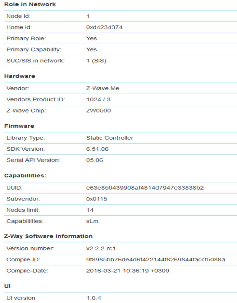
26
The
second
b
l
oc
k
g
i
v
es
det
a
il
ed
i
nf
or
m
a
t
i
on
about
the
Role
of the
c
ont
r
ol
l
er
in the
network,
the
Z
-
Wa
v
e
tran
s
c
e
i
v
e
r
hardware used,
f
i
rm
w
a
re
ru
nn
i
n
g
on
the Z-Wave
t
r
a
n
s
c
e
i
v
e
r
and the
r
e
l
e
a
s
e
in
f
o
r
m
a
t
io
n
of
the
Z
-
Wa
y
so
f
t
w
a
r
e
.
This
i
n
f
o
r
m
a
t
i
o
n
may
be needed d
u
r
i
n
g
support
and
d
e
b
u
gg
i
n
g
.
The
c
ont
r
ol
l
er
is a
s
p
ec
i
a
l
node
in the
network but
still a
node. Therefore buttons
allow
a
cc
es
s
i
ng
the
d
ev
i
c
e
sp
e
c
i
f
i
c
data
of
the
c
o
n
t
r
o
ll
e
r
and issue
a
Node
I
nf
o
r
m
a
t
i
o
n
Frame.
A
third button
g
i
v
es
access
to the
c
o
nt
r
o
ll
er
sp
e
c
i
f
i
c
data.
Most of
these data
is only
r
e
l
e
v
a
n
t
to
d
e
v
e
l
o
p
e
r
s.
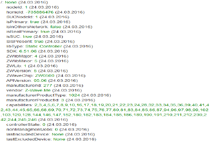
27
The last
b
l
oc
k
shows
the
availability
of the
f
unc
t
i
on
calls on the serial API
between
the
Z-Wave
t
r
a
n
s
c
e
i
v
e
r
and
Z- Way. ‘Not
im
p
lem
e
n
t
e
d
’
means that
Z-Way is
e
i
t
h
e
r
not
k
n
o
w
i
n
g
about the
f
un
c
t
i
o
n
i
n
d
i
c
a
t
e
d
by the
f
un
c
t
i
o
n
I
D
or
does
not
make
any
use
of it. A
red
f
un
c
t
i
on
call
i
d
or
name
i
n
di
c
a
t
e
d
that
Z-Way is
a
b
l
e
to
use
this
f
un
c
t
i
o
n
but
the
t
r
a
n
s
c
e
i
v
e
r
s
f
i
r
m
w
a
r
e
did
not
report
to
offer
this
s
e
rv
i
c
e
.
Z
-
Wa
v
e
T
e
r
m
s
The
f
ol
l
ow
i
ng
Z-Wave terms are used
in this
m
a
nu
a
l
:
•
Stat
i
ccont
r
o
ll
er is a Z-Wave device with capabilities to manage the network available on
a
fixed location in the
home
•
Sec
ur
e
env
ir
onment:For
s
e
n
s
i
t
i
v
e
a
pp
li
ca
t
i
o
n
s
like
door
lock
co
n
t
r
o
l
Z-.Wave
offers an
e
nh
a
n
c
ed
enc
r
y
p
t
i
o
n
wr
a
pp
i
ng
d
ef
i
ned
in the
command
class
Sec
ur
i
t
y
.
•
Cont
r
o
ll
e
rR
e
p
li
c
a
t
i
on:
Copy the
i
n
fo
r
m
a
t
i
o
n
of
one
c
o
n
t
r
o
ll
e
r
to
a
n
o
t
h
e
r
c
o
n
t
r
o
ll
e
r
•
SI
S
:
The c
e
n
t
r
a
l
database
of
nodes and
i
ds
.
•
Pr
i
ma
r
yCont
r
o
ll
e
r
:IfnoSISis
present one controller becomes the primary controller
only
able
t
o
include new
d
e
v
ic
e
s
•
Seconda
r
yCont
r
o
ll
er:Ifno SISis
present,
all
other
c
o
n
t
r
o
ll
e
r
s
than the
p
r
i
ma
r
y
c
o
n
t
r
o
ll
e
r
a
r
e
ca
ll
e
d
s
e
co
n
da
r
y
•
Inc
lu
s
ion:the process of bringing new Z-Wave devices into a
network
•
Ex
c
l
u
s
i
on:the process of removing Z-Wave devices from the
network
•
As
s
oc
i
at
i
on is a
c
o
n
t
r
o
l
relationship between
a
controlling device and
a
controlled
d
e
v
ic
e
•
As
s
oc
i
at
i
on G
r
ou
p
is the list of
d
ev
i
c
es
c
o
nt
r
o
ll
er
by
a
ss
oc
i
a
t
i
on
•
Sw
i
tchM
ul
t
il
evel,
Sw
i
tchB
i
na
r
yand
B
a
s
i
c
are certain command
c
l
as
s
e
s
•
No
d
e
I
n
f
o
r
mat
i
on
F
r
am
e
is a
s
p
e
c
ia
l
wi
r
e
l
e
ss
message
i
ss
u
e
d
by
a
Z-Wave
d
e
v
i
c
e
to
announce
its
c
apab
ili
t
i
e
s
and
f
un
c
t
i
o
n
s
.
Comman
d
Cl
a
ss
e
sCont
r
o
ll
e
d
/
S
u
pp
o
r
t
e
d
:
Alarm V2 Controlled, Alarm Sensor V1 Controlled , All Switch V1 Controlled, Application Status V1 Supported, Association V2
Supported and Controlled, Association Group Information V1 Supported and Controlled, Basic V1 Supported + Controlled,
Battery V1 Controlled, Binary Sensor V2 Controlled, Binary Switch V1 Controlled, Central Scene V1 Controlled, Climate Control V1,
Controlled, Clock V1 Supported and Controlled, Configuration V1 Controlled, CRC16 V1 Supported + Controlled, Device Reset
28
Supported + Controlled, Door Lock V1 Controlled, Door Lock Logging V1 Controlled, Firmware Update V1 Controlled, Indicator
V1 Controlled, Manufacturer Specific V1 Supported + Controlled, Meter V3 Controlled, Meter Table V1 Controlled, Multichannel
V3 Controlled, Multichannel Association V2 Controlled, Multicommand V1
Controlled, Multilevel Sensor V6 Controlled, Multilevel Switch V3 Controlled + Supported, Node Naming V1 Controlled +
Supported,
Powerlevel V1 Supported + Controlled, Protection V2 Controlled, Scene Activation V1 Supported + Controlled, Scene Actuator
Conf V1
Controlled, Scene Controller Conf V1 Controlled, Security V1 Supported and Controlled, Sensor Configuration V1 Controlled,
Thermostat Fan
Mode V3 Controlled, Thermostat Fan State V3 Controlled, Thermostats Mode V3 Controlled, Thermostat Operating State V1
Controlled,
Thermostat Setpoint V3 Controlled, Time V2 Supported + Controlled, Time Parameter V1 Controlled, User Code V1 Controlled,
Version V2
Supported + Controlled, Wakeup V2 Controlled, Z-WavePlus V1 Supported + Controlled
Support
Should you encounter any problem, please give us an opportunity to address it before returning this
product. Most questions regarding Z-Wave wireless communication standard can be answered through
the international community at www.z-wave.info
FCC STATEMENT :
This device complies with Part 15 of the FCC Rules. Operation is subject to the following two conditions:
(1) This device may not cause harmful interference, and
(2) This device must accept any interference received, including interference that may cause undesired
operation.
Warning: Changes or modifications not expressly approved by the party responsible for compliance
could void the user's authority to operate the equipment.
NOTE: This equipment has been tested and found to comply with the limits for a Class B digital device,
pursuant to Part 15 of the FCC Rules. These limits are designed to provide reasonable protection
against harmful interference in a residential installation. This equipment generates uses and can radiate
radio frequency energy and, if not installed and used in accordance with the instructions, may cause
harmful interference to radio communications. However, there is no guarantee that interference will not
occur in a particular installation. If this equipment does cause harmful interference to radio or television
reception, which can be determined by turning the equipment off and on, the user is encouraged to try
to correct the interference by one or more of the following measures:
Reorient or relocate the receiving antenna.
Increase the separation between the equipment and receiver.
Connect the equipment into an outlet on a circuit different from that to which the receiver is
connected.
Consult the dealer or an experienced radio/TV technician for help.
FCC Radiation Exposure Statement:
This equipment complies with FCC radiation exposure limits set forth for an uncontrolled environment.
This equipment should be installed and operated with minimum distance 20cm between the radiator &
your body.