Elk ELK-6023 RECESSED DOOR SENSOR User Manual 6023 Recessed Dr Wnd Xtmr Instruction pmd
ELK Products, Inc. RECESSED DOOR SENSOR 6023 Recessed Dr Wnd Xtmr Instruction pmd
Elk >
USERS MANUAL
ELK-6023 Wireless Recessed Door Sensor
FCC AND IC COMPLIANCE STATEMENT:
This device complies with Part 15 of the FCC Rules and Industry Canada License-Exempt RSS Standards. Operation is subject to the following two
conditions: (1) This device may not cause harmful interference, and (2) This device must accept any interference received, including interference that may
cause undesired operation.
Under Industry Canada regulations, this radio transmitter may only operate using an antenna of a type and maximum (or lesser) gain approved for the
transmitter by Industry Canada. To reduce potential radio interference to other users, the antenna type and its gain should be so chosen that the equivalent
isotropically radiated power (e.i.r.p.) is not more than that necessary for successful communication.
Conformément à la réglementation d’Industrie Canada, le présent émetteur radio peut fonctionner avec une antenne d’un type et d’un gain maximal (ou
inférieur) approuvé pour l’émetteur par Industrie Canada. Dans le but de réduire les risques de brouillage radioélectrique à l’intention des autres utilisateurs,
il faut choisir le type d’antenne et son gain de sorte que la puissance isotrope rayonnée quivalente (p.i.r.e.) ne dépassepas l’intensité nécessaire à
l’établissement d’une communication satisfaisante.
PO Box 100 3266 US Hwy 70 West
Hildebran, NC 28637
Ph 828-397-4200 Fax 828-397-4415 http://www.elkproducts.com
Front Page
Operational Testing
A two color LED on the sensor circuit board displays feedback
of transmission status. This is useful during installation and
troubleshooting but is not viewable after sensor is installed.
GREEN blink = Good
Sensor has successfully transmitted a violation (alarm)
transmission to the transceiver and that signal has been
received and acknowledged by the transceiver. The green blink
is not provided for a sensor restore transmission.
RED blink = CAUTION
Indicates that sensor was unable to communicate with the
transceiver after multiple repeated attempts. The distance
between the sensor and the transceiver may be too great.
Another possibility is that the transceiver is disconnected or
powered off. Try the following troubleshooting steps:
A. Verify transceiver is on with its status LED blinking.
B. Trip another sensor to determine if it can successfully
communicate with the transceiver.
If steps A & B pass, try moving the sensor closer to the
Transceiver and re-test. If sensor communicates at a closer
range then one of two solutions may be needed:
1. Relocate the transceiver to a closer and/or more central
location to this and all other sensors.
2. Purchase and install an additional “remote” transceiver to
cover the area where this sensor was mounted.
Per UL a complete test of the security system and all zones
should be performed once a week. The zones may be walk
tested using the M1 Keypad Menu 3 - Walktest Area.
Sensor Location & Mounting
Choose a location on the lock “latch” side of the door. Do not
mount on hinge side! Install the sensor in the jamb and the
magnet in the door. There must be a minimum 1/8” gap between
the door and door jamb. For best wireless operation install at
least 5’ or higher above the finished floor.
Not recommended for use on metal doors. Metal can negatively
affect the wireless performance. Observe temperature and
humidity specs. Do not install in areas of high moisture/humidity
WARNING: Carefully read and follow directions below before
drilling or attempting to install. When drilling, use caution to
avoid striking or drilling into any door glass or sidelights. .
1. Remove sensor end plug using a small flat screwdriver to
gently pry up in the slot provided. Do not misplace plug.
2. Using fingers only, grasp the edge of the circuit board and
pull straight out to remove board from the housing.
3. Enroll the sensor into control using either of the two methods
outlined in next section. After enrollment slide the board
back into the housing and replace the end plug.
4. Hold sensor close to the intended location and verify it
operates properly prior to drilling any holes. Do not proceed
with drilling or mounting until proper operation is confirmed.
5. At the intended location draw a horizontal pencil line across
the jamb from the door stop to the edge. Measure back
from the stop a distance 1/2 the thickness of the door. Mark
this as the centerline drill point for the sensor. If the door
jamb has weatherstripping be sure to allow for its thickness
when the door is in the closed position.
6. For the sensor drill a 3/4” wide by 3” deep hole at the
centerline mark. A brad point bit is suggested as it reduces
chipping and tearing. Remove all sawdust and debris.
7. Carefully slide the sensor into the hole until only the flange
is exposed. Do Not Force. Secure with #4 flat head screws.
8. The magnet and sensor must be properly aligned for reliable
operation. The vertical alignment is best achieved by
swinging the door closed so that the horizontal line on the
jamb can be transposed over to the door edge. For
horizontal alignment it’s generally best to make test marks
and then close the door to visually verify which mark best
aligns with the sensor.
9. For the magnet drill a 3/4” wide by 1” deep hole at the
centerline mark using a brad point bit. Remove all sawdust
and debris and press fit magnet into hole.
APPLICATION
The ELK-6023 Wireless Recessed Door Sensor is the ultimate
wireless security device for discriminating customers. It mounts
into a 3/4” drilled hole in a wooden door jamb and becomes
nearly invisible once the door is closed. It features Elk’s Industry
Leading Two-Way Technology with positive signal
acknowledgment, extended range, and long battery life. It
works with Wireless Transceivers and Controls that accept Elk’s
two-way technology; such as, the ELK-M1XRFTW. Each time
the 6023 transmits it sends a unique TXID identifier and a Loop
number.
SPECIFICATIONS:
Frequency: 902 Mhz - 928 Mhz frequency hopping
Tamper: Microswitch detects removal of cover.
Dimensions: .75”D x 2.5”L Mag: .75”D x 1”L
Maximum Operating Gap of Reed: 3/4”
Operating Temperature: 32° to 120° F (-0° to 49°C)
Location: Designed for wood (non-metal) or vinyl doors only
Relative Humidity: 5-85% Non-Condensing
Battery: 3.6V Lithium 1/2 AA size - See Battery Installation
Unique TXID Code: Over 1 million combinations
Printed In USA
L6?? Rev A 2/6/2014
CAUTION: Do not reverse the battery polarity!
- +
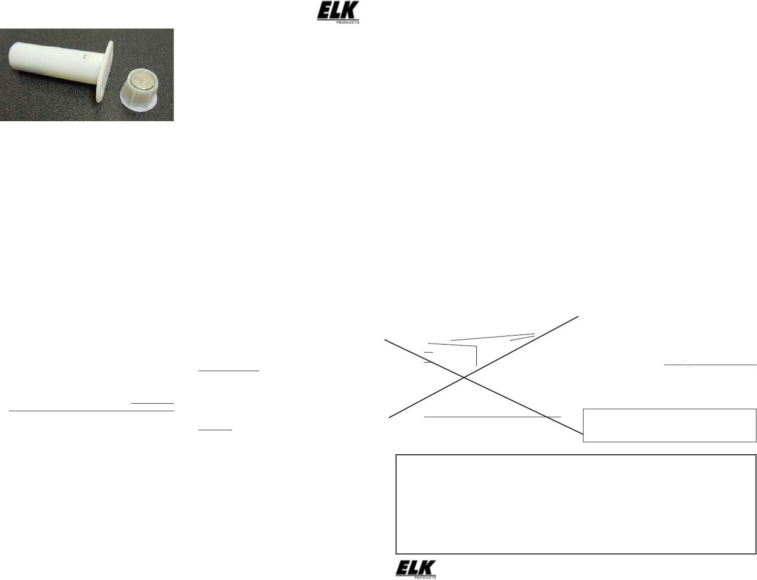
Figure 2. ELK-6023 Sensor & Housing
Mounting
Holes
Alignment
Marks
Maximum
Operating
Gap = 3/4”
3/4”
Figure 1. ELK-6023 Mounting Gap and Alignment
Battery Installation and Replacement
Low Battery trouble will be transmitted when the sensor battery
needs to be replaced. Approved 3.6V Lithium Batteries are:
Xeno XL-050F
1. Remove the sensor cap (dime sized) by inserting the tip of
a small flat screwdriver in the provided slot and gently prying.
Carefully extract the circuit board from the housing..
2. Remove old battery and WAIT AT LEAST 20 SECONDS
before installing new battery.
3. Observe correct polarity when installing new battery. Do
not bend or damage the metal battery holder leafs.
4. Test sensor operation with panel. Trip sensor several times
to send an “all good” and clear the low battery trouble.
Limited Warranty
The 6023 Wireless Recessed Door Sensor is warranted to be
free from defects and workmanship for a period of 2 years from
date of manufacture. Batteries used with wireless devices are
not warranted. Elk makes no warranty, express or implied,
including that of merchantability or fitness for any particular
purpose with regard to batteries used with wireless devices.
Refer to Elk’s website for full warranty statement and details.
NOTE: ELK PRODUCTS IS NOT RESPONSIBLE FOR ANY CHANGES OR MODIFICATIONS NOT EXPRESSLY APPROVED BY THE PARTY
RESPONSIBLE FOR COMPLIANCE. SUCH MODIFICATIONS COULD VOID THE USER’S AUTHORITY TO OPERATE THE EQUIPMENT.
ELK-6023 Wireless Recessed Door Sensor FCC ID: TMAELK-6023 IC: 4353A-6023
BATTERY WARNING: Risk of fire, explosion and burns. Do
not attempt to recharge or dissassemble. Do not incinerate
or expose to heat above 212° F (100° C). Dispose of used
batteries properly. Keep away from children.
The ELK-6023 is intended to be installed in accordance with:
The National Electrical Code, ANSI/NFPA 70.
Final picture will
come after tooling
Enrolling from ElkRP Software
1. Launch ElkRP and open the desired Customer Account file.
2. If no wireless zones currently exist in this M1 you will need
to create a group of 16 wireless zones. In the folders column
right click on Zones (Inputs) and then click New Wireless
Zones. Place a check mark in the box beside the desired
group, then click OK. Repeat if additional wireless groups
are required. All expanded zones must be defined in groups
of 16. The M1XRFTW wireless must always start at Zone
17 (Group 2) and the last wireless zone CANNOT be higher
than Zone 160 (Group 10).
Note: M1 only allows Zones 17 to 160 to be used for
wireless zones (max. of 144 wireless sensors). If a large
number of wireless zones are expected, avoid conflict
with any future Hardwired Zones in the range of zones
17 to 160 by NOT enrolling any Hardwired Zone
Expanders (M1XIN) at data bus address 10 or lower.
3. Double click on Wireless - Group _ (the group just added),
then double click one zone at a time to define a name, type,
and options. Repeat for each wireless zone. It is more
time efficient to use ElkRP to program the Zone Definitions
(name, type, and options) before moving to the Wireless
Setup for entering the TXID and Loop number.
4. From the Folders column double click on Wireless Setup
to setup and enroll the wireless sensors.
4a. Click the Transmitters tab, then double click a zone.
4b. Place a check mark in the Enabled box.
4c. Set Supervision type as: 1=Normal “Burg” Supervision
You will notice there are 2 other supervision options
displayed: 0=Non Supervised & 2=Fire Supervision
4d. Skip down to the TXID box and enter the Sensor TXID
from the printed label located on the sensor.
4e. Skip to the LOOP box and enter a 2. Loop 2 defines the
built-in reed switch.
4f. Click Save. Repeat the entire step 4 for each additional
Wireless Zone and Sensor. Don’t forget to Send
changes to the M1.
Enrolling from M1 Keypad Installer Programming
1. Enter M1 Keypad Installer Programming and navigate
to Menu: 14-Wireless Setup
2. Press right arrow, then scroll up to Sub-Menu: 3:Learn Sel
WirelessTransmtr
3. Press right arrow, then scroll or select a unused/available
WZone (wireless zone).
4. Press right arrow to Lrn (Enroll) a new sensor.
5. Insert the Battery into the sensor as soon as the keypad
displays: Push Transmitter Button. The M1G voice will
speak; “Press Transmitter button for zone xx”.
NOTE: If battery is already installed; remove it, wait
20 seconds, then re-insert.
6. Upon successful enrollment the Keypad will chime and
briefly display the 6 digit TXID code of the sensor.
If enrollment fails the TXID will not display. If that occurs;
remove the battery, wait 5 seconds, then re-insert. In
certain instances it may be necessary to repeat steps 3 -
6.
7. The Rapid-Enroll feature will auto advance to the next
wireless zone in sequence and wait for the next sensor
enrollment. Simply repeat step 5 for each additional sensor.
8. To end Rapid-Enroll after all wireless zones (sensors) have
been enrolled press the ELK key one time.
9. Set the Loop Number. ELK wireless sensors use Loop 2
for the built-in reed switch. Since the 6023 only has the
single “reed switch” zone, the default M1 Loop # 0 will
recognize the reed switch WITHOUT the need to change
the Loop from 0 to 2. If you wish to view (or change) the
Loop #, scroll up or down to the desired M1 wireless zone
and press the left arrow. The screen will display a 9 digit
number (TXID in decimal) followed by Loop=.
10. Supervision - For wireless Burg sensors the supervision
should be set to 1=Normal “Burg”. This is the factory
default setting for all wireless zones. To view or change
the Supervision value, press the ELK key to locate Sub-
Menu: 2:Xmit Transmitter Opt. Press the right arrow and
scroll to the wireless zone, then press right arrow to select.
ZONE DEFINITION: After all wireless zones have been
enrolled proceed to Menu: 5 - Zone Definitions to program
the name, zone type, and any desirable options.
IMPORTANT: An ELK-M1XRFTW Receiver must be installed
and enrolled with the M1 Control before any attempt to install
or enroll wireless sensors.