Elk ELK-6050 SMOKE DETECTOR User Manual 6050 Smoke Det Instruction Rev E pmd
ELK Products, Inc. SMOKE DETECTOR 6050 Smoke Det Instruction Rev E pmd
Elk >
USER MANUAL

ELK-6050 Wireless Smoke Detector Page 1
ELK-6050
Wireless Photoelectronic Smoke Detector with
built-in rate-of-rise and fixed temp Heat Sensor
For the latest downloadable version of this manual visit our website: http://www.elkproducts.com
Installation Instructions
Applications and Overview
The ELK-6050 Wireless Smoke Detector is designed for use with Elk's
two-way wireless product line consisting of the ELK-M1XRFTW Trans-
ceiver and the ELK-M1 Control. It is intended for residential and light
commercial applications and incorporates many features designed to
ensure its reliable performance.
The 6050 is powered by long life 3V Lithium batteries, providing power
to both the detector and the built-in wireless transmitter. The unit utilizes
photoelectric smoke detection technology, and also includes fixed
temperature 135°F heat detection and rapid "rate-of-rise" temperature
detection. Built-in self-diagnostics monitors sensitivity and operation
status. Should the unit drift out of the UL Listed sensitivity range or fail
the internal diagnostics, it will extinguish its Alarm/Status LED and signal
a trouble condition to the Control. This detector meets NFPA 72 field
sensitivity testing requirements without the need for external meters. A
sensitivity test feature provides visual indication of the sensitivity level
and warns if service is required. Built-in drift compensation allows the
product to adjust sensitivity automatically as it becomes dirty over time.
The drift compensation feature dramatically increases the time between
cleanings, as well as reducing the chance of nuisance alarms.
Specifications
Operating Voltage: 3 VDC
Typical Standby Current: 35 µA
Typical Alarm Current: 70 mA
Battery Type: 3V Lithium x 2, Panasonic CR123A, Sanyo
123A, Duracel DL123A (5 to 7 year life in
typical usage)
Smoke Detection: Photoelectronic
Heat Detection: Fixed 135°F ± 5°F (57.2°C ± 2.8°C)
Rate-of-Rise 15°F/min>105°F (8.3°C/
min>40.6°C)
Built-in Sounder: 85 dBa at 10’ temporal pattern
Low Battery Beep Rate: 1 every 45 seconds.
Wireless Freq: 900 MHz
Dimensions: 5.6" x 2.4" (14.2cm x 6.1cm)
Operating Temperature: 40 to 100°F (4.4 to 37.8°C)
Operating Humidity: 0 to 95% non-condensing
Agency Listings: UL217, CE, C-UL US, CSFM
About This Guide
This Guide describes the installation, operation, and maintenance of this
product. Please read these instructions thoroughly prior to installation.
Installer: This document should be left with the owner/user.
Owner/User: Keep this document in a handy location and refer to it
when you have questions about this products functions or features.
Reading this guide is the only way to learn how to use your product
wisely and to know how to react in the event of an alarm. This product
is a member of a reliable, high-quality product family using the latest
technology available. Review the information in this section to
ensure you get the most out of the product. The information in this
User Guide is in accordance with NFPA 72 and/or CAN/ULC-S524,
depending on country of installation.
Components List
Smoke Detector electronics assembly
Mounting Baseplate
Mounting Screws and Anchors
Two CR123A lithium batteries
This User Guide
Two-way Communications
When multiple ELK-6050 Smoke Detectors are installed and enrolled into
the same Control the two-way communications features offered by the
Elk wireless permit certain communications to flow in both directios. For
example; whenever any 6050 Smoke Detector alarms and the alarm is
communicated to the Control, the Control will broadcast a signal to all other
enrolled 6050 Smoke Detectors informing them to turn on their sounder.
Likewise, whenever the alarm is silenced at the Control, a broadcast will
be transmitted to silence the other "like" detectors. EXCEPTION: If smoke
is still present in a detector, that detector will not cease sounding until the
smoke has been cleared. Below is a complete listing of the two-way
communications signals:
Alarm - Sent from 6050 to the Control advising that the
detection chamber has sufficient smoke or heat to
qualify as an alarm condition.
Trouble - Sent from 6050 to the Control advising that the
detector has an internal fault and may require
service.
Low - Sent from 6050 to the Control advising that the
Battery batteries have reached a low voltage state and
must be replaced to maintain proper operation.
Test/Silence - Sent from 6050 to the Control advising that the Test
Button was pressed on a detector which was
sounding an alarm. The Control will treat this a a
silence the Fire audible signal..
Sounder On - Sent from Control to all enrolled 6050 Smoke Detectors
informing them to activate their sounder.
Sounder Off - Sent from Control to all enrolled 6050 Smoke Detectors
informing them to silence their sounder. This is
triggered by the silencing of the Fire Audible. NOTE:
A detector will not silence if it continues to detect
smoke or heat.
Trouble Off - Sent from Control to all enrolled 6050 Smoke Detectors
informing them to silence their trouble chirps. In the
case of a low battery trouble chirp, if the batteries
are not replaced then the chirp will re-start after 24
hours.
Alarm/
Status LED
Heat Sensor
and Ack LED
Test/Silence
Button
Alarm
Sounder
Heat
Sensor
Page 2 ELK-6050 Wireless Smoke Detector
WARNING! LIMITATIONS OF SMOKE DETECTORS
yWireless smoke detectors are very reliable, but may not work under
all conditions. No fire alarm provides total protection of life or property.
Smoke detectors are not a substitute for life insurance.
ySmoke Detectors require a source of power to work. This
smoke detector will not operate and the alarm will not sound if batteries
are dead or not installed properly.
ySmoke Detectors may not be heard. A sound sleeper or someone
who has taken drugs or alcohol may not awaken if the alarm is installed
outside a bedroom. Closed or partially closed doors and distance can
block sound. This alarm is not designed for the hearing impaired.
ySmoke Detectors may not always activate and provide warning
early enough. Smoke detectors only activate when enough smoke
reaches the alarm. If a fire starts in a chimney, wall, roof, on the other
side of closed doors, or on a different level of the property, enough
smoke may not reach the alarm for it to alarm.
ySmoke Detectors are a significant help in reducing loss, injury and even
death. However, no matter how good a detection device is, nothing
works perfectly under every circumstance and we must warn you that
you cannot expect a smoke alarm to ensure that you will never suffer
any damage or injury.
yCurrent studies have shown smoke detectors may not awaken all
sleeping individuals. It is the responsibility of individuals in the household
that are capable of assisting others to provide assistance to those who
may not be awakened by the alarm sound, or to those who may be
incapable of safely evacuating the area unassisted.
WHERE TO INSTALL
Warning: As a minimum requirement, smoke detectors must be installed in
accordance with the National Fire Protection Agency (NFPA) Standard 72,
Chapters 2, 3, and 5, which define the standards for the National Fire Alarm
Code (National Fire Protection Association), Batterymarch Park, MA 02269-
9101). Depending on the application, you may need to reference other
chapters of NFPA 72 or NFPA 101.In addition, observe all local and national
building and electrical codes. See back page for listing of NFPA Guidelines.
When choosing an installation location, consider:
o Use of structure and type of construction
o Contents you want to protect and their burning characteristics
o Human occupancy
o Total area to be monitored
o Ceiling height and surface condition
o Air movement and vent locations
o Obstructions
o Deflections
After considering these factors, choose a location:
o Where the temperature range is between 40° and 100° F (4.4° and
37.8° C).
o Where the humidity is between 0 and 90% non-condensing.
o Away from ventilation sources that can prevent smoke from reaching
the smoke alarm.
o That is at least 5 feet (1.5 m) from bathrooms.
When placing the product on a ceiling, mount it in the center of the room
or hallway, at least 4 inches (10cm) away from any walls or partitions.
When mounting the product on a wall, place it so the top is 4 to 12 inches
(10 to 31cm) below the ceiling.
In rooms with sloped, peaked, or gabled ceilings, place smoke alarms 3
feet (.9 m) down or away from the highest point of the ceiling.
If mounting to suspended ceiling tile, secure the tile with the appropriate
fastener to prevent tile removal.
Smoke detectors are not to be used with alarm guards unless the
combination has been evaluated and found suitable for that purpose.
Note: A smoke detector does not provide warnings for fires resulting from
explosions, smoking in bed, or other furniture; ignition of flammable liquids,
vapors and gasses; and children playing with matches or lighters.
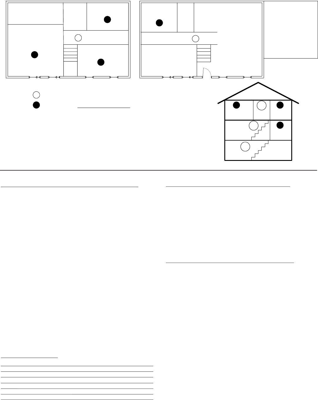
Bedroom 1
Den
Living Room
Kitchen
Basement
1st Floor
In homes basements or multiple levels at least one smoke detector shall be on each level.
A Smoke Detector shall be located in the hallway outside the entrance to any bedroom areas.
In new construction an additional Smoke Detector shall be installed in each sleeping area
2nd Floor
S
S
S
S
Dining
Garage
Master
Bedroom
Bedroom 2
Bath
S
Master
Bath
Bedroom 3
SBath
S
S
S
S S
S
S
SRequired Smoke Detector – Absolute Minimum
Additional Smoke required in new construction and for additional protection

ELK-6050 Wireless Smoke Detector Page 3
Locations to Avoid
o Areas where normal ambient temperature exceeds 100° F (37.8° C).
o Dirty, dusty, insect infested areas.
o In or near areas with combustion particles (kitchens, garages,
furnaces, hot-water heaters, gas space heaters).
o On the ceiling in rooms next to kitchens, where there is no transom
between the kitchen and such rooms.
o Damp or humid areas, or near bathrooms with showers.
o Near fresh-air inlets or returns or very drafty areas.
o Near heating/air conditioning vents, fans, and fresh air intakes, which
can drive smoke away from the smoke alarm.
o In dead-air spaces at the top of peaked ceilings or in corners where
walls and ceiling meet. Dead air can prevent smoke from reaching a
smoke alarm/alarm.
o Within 10 feet (3 m) of fluorescent light fixtures.
o Not suitable for outdoor use.
In Case of Fire
o Leave immediately. Don’t stop to pack or search for valuables.
o In heavy smoke, hold your breath and stay low, crawl if necessary.
The clearest air is usually near the floor.
o If you have to go through a closed door, carefully feel the door and
door knob to see if undue heat is present. If they seem cool, brace your
foot against the bottom of the door with your hip against the door and
one hand against the top edge. Open it slightly. If a rush of hot air is
felt, slam the door quickly and latch it. Unvented fire tends to build up
considerable pressure. Be sure all members of the household realize
and understand this danger.
o Use your neighbor’s phone or a street fire alarm box to call the fire
department. The job of extinguishing the fire should be left to the
professionals.
Be Prepared
Practice the following steps to prepare you and your family in the event
of a fire:
o Perform fire drills regularly. Use them to assure recognition of an alarm
signal.
o Draw a floor plan and show two exits from each room. It is important
that children be instructed carefully, because they tend to hide in times
of crisis.
o Establish one meeting place outside the home. Insist that everyone
meet there during an alarm. This will eliminate the tragedy of someone
reentering the house for a missing member who is actually safe.
o If you have children and/or physically challenged people residing in
your household, use window decals to help emergency personnel
identify the sleeping quarters of these individuals.
IMPORTANT:
It is recommend that the Smoke Detector be enrolled
(added) into the Control and a Full-Test be performed
prior to permanently mounting the detector in the
intended location.
Mounting the Smoke Detector
Please enroll (add) the Smoke Detector into the Control and
perform a Full-Alarm test with the detector temporarily
positioned in the intended mounting location. This shoud be
done PRIOR to permanent mounting to help ensure that the
location is suitably in range of the wireless Transceiver and/or
the Control. A little extra time and a few steps now can often
save loads of time later.
A. Before mounting disconnect or disable any alarm-notification
appliances (bells, sirens), any service-release devices, and any
extinguishing systems that may be a part of the Control panel. Test
communications between the control panel and smoke detector
before permanently mounting. Test as follows:
oHold the Smoke Detector in the approximate location where it is
to be installed.
oPress the alarm test button on the front of the unit for approximately
4 seconds. The built-in sounder should go into alarm and a
wireless alarm transmission should be sent to the Control.
oAt the Control Keypad, verify that the signal was received and that
the Fire Alarm sounded. If no signal is received or the RF signal
is low, relocate the smoke alarm and retest.
B. Using two supplied screws and anchors, mount the detector baseplate.
Note: NEVER attach this Smoke Detector to a removable ceiling panel
unless some form of span support bracket is utilized. The best
recommendation is to always mount directly to the metal grid support
of the removable ceiling panels.
C. Attach the Smoke Detector to the mounting baseplate as follows:
oLine up the raised alignment tab on the lip of the detector with the
alignment arrow on the mounting base.
oInsert the detector into the base and turn clockwise about 15
degrees until it snaps into place.
Note: The product is designed so that it cannot be attached to the mounting
base if no batteries are installed.
D. Test communications between the Smoke Detector and the Control
once again.
- Press the Test button on the front of the unit for 8-to-10 seconds.
Both the unit itself and the Control should sound an alarm.
- Verify the alarm and silence at the Control by entering a valid User
Code.
E. The Control and all auxiliary functions should be verified for a complete
test of the system.
Alignment arrow
Alignment tab

Page 4 ELK-6050 Wireless Smoke Detector
Normal Mode Operation
o In normal operation, the Alarm/Status LED should flash once every
16 seconds.
o In alarm mode, the Alarm/Status LED should be ON – Red Color.
o In trouble or maintenance mode, the Alarm/Status LED is OFF.
Silencing an Alarm or Low Battery
o Press the Test/Silence button to silence the sounder during an alarm
and will also silence a Low Battery trouble chirp.
o After a few minutes the sounder and alarm will resume if smoke is
still present in the detection chamber.
Tamper Protection
A Fire Trouble signal will be transmitted to the Control when the Smoke
Detector front housing is removed from the backplate. Replacing the
detector onto the baseplate should restore the Fire Trouble condition.
Batteries
When the batteries become low the 6050 will extinguish its Alarm/Status
LED and communicate a low battery trouble to the Control. It will sound a
local chirp every 45 seconds until the batteries are replaced. The low
battery chirp can be silenced for 24 hours by pressing the Test/Silence
button. Estimated battery service life is 5 - 7 years in typical usage.
Replacing / Installing Batteries
Use only 3V lithium CR123A batteries, as listed on the battery compart-
ment cover. Replace both batteries at the same time.
A. Remove the Smoke Detector from the baseplate by grasping the
front housing and twisting counterclockwise.
B. Slide the battery compartment cover away from the smoke alarm
to unsnap it and lift it off (see the figure below).
C. Remove and dispose of (recycle) the batteries appropriately.
D. WAIT AT LEAST 20 SECONDS after removing the old batteries
before installing the new batteries.
E. Observe correct polarity and insert two new 3V lithium batteries
into the battery compartmen. Lay the black ribbon in behind the
new batteries as they are installed.
Note: Use only new batteries when replacing old batteries. Do not
replace with batteries that were used previously. Use of a
different battery can detrimentall affect the smoke alarm opera-
tion. Caution: Constant exposures to high or low humidity may
reduce battery life.
F. Replace the flat cover over the battery compartment.
G. Align the raised alignment tab on the lip of the smoke alarm with
the arrow on the mounting base and reattach the smoke alarm to
the mounting baseplate.
H. Test the Smoke Detector and the Control to verify operation.
RF ACK (Acknowledge) Green & Orange/Red LED
This LED is located near the detector's Test/Silence button, but down
inside the cavity where the heat sensor is located. This LED helps provide
a way to verify that the wireless (RF) communications to the Control. The
LED will briefly flash Green if successful, or Orange/Red if unsuccessful.
To view this LED it may be necessary to look directly into the heat sensor
cavity. Bright lighting may hinder this viewing.
GREEN blink = Detector has successfully communicated to the Control
and the signal was positively acknowledged.
ORANGE/RED blink = Detector was not successful in communicating to
the Control after multiple attempts. Refer to the Troubleshooting
section of this manual.
Full-Alarm Testing of the Smoke Detector
This sensor may be tested during install or at anytime after. At a minimum
It is recommended the product be tested annually in-place.
NOTE: Prior to conducting any testing ALWAYS contact your Central
Monitoring Station to inform them of the impending test.
A. Use Smoke! in a can® and follow the directions on the can.
B. Or hold a smoldering punk or cotton wick close to the unit and gently
direct the smoke into the smoke entry openings for 20 seconds or
until an alarm is indicated.
The Alarm/Status LED should illuminate, the sounder should emit a
temporal 3 pattern, and the Control should be indicating a Fire alarm
condition. Fan the detector to clear the smoke source and stop the
local alarm. Enter a valid User Code at the Control Keypad to silence
and reset the alarm. Extinguish the smoke source after testing!
LOCAL (non-alarm) Testing of the Smoke Detector
The detector's operation with the Control can also be tested WITHOUT
causing a full alarm using the Control Walk Test mode (User Menu #3). This
DOES NOT TEST or confirm the operation of any alarm notification
appliances (Sirens/Bells), nor does it test the Central Station Communi-
cations. Use the Full-Alarm testing procedures for those purposes.
A. Place the Control in the WalkTest Area mode (User Menu #3).
While in the Walk Test the communicator does not send
alarms to the Central Monitoring Station.
B. Locate the Test/Silence button on the Smoke Detector front.
C. Press and hold the Test/Silence button for 4 seconds, then
release. The Alarm/Status LED should blink indicating that the test
has begun. Then the following should occur:
1. The Alarm/Status LED should illuminate solid Red and the built-
in sounder should blast for several seconds.
2. The RF ACK (Acknowledge) LED (located near the Test/Silence
button) should flash Green as soon as the transmission is
acknowledged by the Control.
3. A chime tone should be heard at the keypad where Walk Test
was initiated. You may also hear the Control speak a number
proceeded by the words "level." This is an approximate signal
strength of the sensor's transmission. The higher the better.
4. The same keypad will also display the number of zones that
have successfully been tested. This number increments as
additional zones are tested. Unfortunately there is no way to
view which Smoke Detector zone tested because that portion
of the Walk Test is only designed for Burglary tested zones.
D. When satisfied with the test results press the " * " or Clear key to
exit the Walk Test Area mode.

ELK-6050 Wireless Smoke Detector Page 5
Enrolling into Control from Keypad Programming
Each wireless sensor is programmed with a unique TXID number when
manufactured. The unique ID must be enrolled into the control panel at
the time of installation, allowing the detector to communicate with that
specific control panel.
1. Make sure the M1XRFTW Transceiver is powered up and enrolled
with the M1 Control.
2. Enter M1 Keypad Installer Programming and navigate to Menu:
14-Wireless Setup
3. Scroll up to sub-menu:3:Learn Sel Wireless Transmtr and press
Select (right arrow).
4. Scroll to and select an unassigned WZone (wireless zone) and
press Learn (right arrow) to enroll.
5. Insert the Batteries into the 6050 as soon as the keypad displays:
Push Transmitter Button. The M1G will speak; “Press transmitter
button for zone xx”. If successful the Keypad will chime and briefly
display the 6 digit TXID code of the sensor. If a TXID is not displayed
then enrollment was not successful. Should this happen, re-
move the batteries, wait 5 seconds, and re-insert.
Rapid-Enroll will auto advance to the next wireless zone in sequence
and wait for the next sensor. Repeat the previous step for each new
sensor.
6. After all wireless sensors are enrolled, press the ELK or Select
Wireless key to stop Rapid-Enroll.
7. Set the Loop ID to Type 2 - To do this scroll to the appropriate
wireless zone and press the HW (left arrow) button. An 8 digit
number (the TXID in decimal) will now display followed by Loop = 0.
Move the cursor to the right (press RIGHT arrow) and enter a "2".
Press the ELK key or the Select Wireless key to back out. The Loop
ID is an identifier sent wireless by the 6050 to the Control. Setting
the Loop ID to 2 is very important as the 6050 detector will not
communicate with the Control unless this is set. The M1 default for
all wireless zones is Loop "0".
8. Set Supervision Type to "1" (Normal Supervision) - To do this
press the ELK or the Select Wireless key to locate Sub-Menu: 2:Xmit
Transmitter Opt. Scroll to the desired wireless zone, press Select
(right arrow) and scroll to Option 2: Supervision Type. Change or
verify that this is set to "1." The Supervision Type informs the Control
to expect a supervisory check-in report from the 6050 detector
approximately every 64 minutes. If set to "0" the control will not
expect a supervisory check-in, thus leaving the device unsupervised.
A separate M1 option sets the number of missed check-ins that will
be allowed before a sensor is declared missing.
9. PROGRAM THE ZONE DEFINITION - This must be done from Keypad
Menu 5 - Zone Definitions for all new enrolled wireless zones.
The Elk-6050 Smoke Detector may be enrolled into the Control using one of the following two methods.
Enrolling into Control using ELKRP software
1. Launch the ElkRP PC software and open the desired Customer
Account file.
2. Click the "+" next to Zones (Inputs) to expand the view. Look to see
if there are any existing wireless zone groups. If there are none then
it will be necessary to add or create a new group. To create a
wireless group, right click on Zones (Inputs) and click New
Wireless Zones. Place a check mark in the box to be added,
starting with Group 2). Click OK. Repeat if more wireless groups
are required.
NOTE: The M1 Control requires all expanded zones to be
defined in groups of 16. E.G. Zones 17-32 = Group 2, zones
33-48 = Group 3, etc. And it requires the M1XRFTW Two-Way
Transceiver to always be enrolled as the first expander
(databus address 2). For this reason, the first group of
wireless sensors must be defined as group 2. M1 allows
a maximum of 144 wireless zones, therefore the last
potential wireless zone will be Zone 160. So, If a large
number wireless zones is ever anticipated, it would be a
good idea to avoid conflict with any future Hardwired Zones
in the 17 to 160 range by NOT enrolling any Hardwired Zone
Expanders (M1XIN) at data bus addresses below 10.
3. Double click on Wireless - Group _ (the group just added) and
double click one zone at a time to define the Zone Name, Definition,
Type, Attributes, etc.
4. The next steps involve setting the sensor's TXID and other wireless
setup. The wireless setup may accessed directly from each zone
definition screen (click the Wireless Setup button) OR from the
ElkRP Wireless Setup in the folders column.
5. Enable the sensor by placing a check mark in the Enabled box.
6. Set the Supervision type to "1" (Normal Supervision) for the
6050. A setting of "0" means the control will not expect a supervisory
check-in from the detector. For additional details refer to Supervision
on the previous page.
7. Skip to the TXID box and enter the detector TXID that is printed
on the small printed label attached to inside back of the detector.
8. Skip to the LOOP box and set the Loop to Type 2. This is very
important as the 6050 will not communicate with the Control unless
this is set.
9. Click Save. Repeat the entire sequence above for additional 6050
detectors or other Wireless Zone sensors.
Don't forget to PROGRAM THE ZONE DEFINITION of the 6050
detector to Fire (Def=10).

Page 6 ELK-6050 Wireless Smoke Detector
Maintenance
This 6050 Smoke Detector is designed for a service life of approximately
8 to 10 years. Even so, the following annual and random maintenance
tests are recommended:
Annual - Smoke Detector Test {Locate and follow the section in
this manual titled: Full-Alarm Testing of the Smoke Alarm
Random - Visually check for LED flashing every 16 seconds
- Perform a Detector Sensitivity Test
Detector Sensitivity Test
This test performs a manual diagnostic of the detector with the results
displayed via flashes of the Alarm/Status LED. To initiate this test:
A. Press and hold the detector Test button for 4 seconds. Once the
test starts, the alarm/status LED will flash 1 to 9 times.
B. Count the LED flashes and view the table below to determine the
results of the sensitivity test and any action required.
IMPORTANT:
If the sensitivity is within limits and all other tests pass, the detector will
go into full alarm mode after the LED flashes stop. This also causes the
Control to go into alarm. The detector will auto-reset after 7 seconds,
but the Control's alarm must be manually reset by entering a User Code.
If the sensitivity is not within limits, or an unserviceable hardware fault
is detected, the LED will remain OFF indicating that the Smoke Detector
must be serviced or possibly replaced.
F
FLASHES MEANING STEPS TO TAKE
1Unserviceable hardware
fault
Reset smoke sensor alarm and rerun
the sensitivity test. If error persists,
replace smoke sensor.
2 - 3 Smoke sensor is becoming
insensitive
Clear smoke sensor, reset it, and rerun
the sensitivity test. If error persists,
replace smoke sensor.
4 - 7 Smoke sensor is within
normal sensitivity range. None.
8 - 9 Smoke sensor is becoming
too sensitive
Verify smoke chamber is snapped down
securely. Clean smoke sensor and
replace the smoke chamber.
Cleaning the Smoke Detector
Clean the cover with a dry or slightly damp (water ONLY) cloth as needed
to keep it free from dust and dirt. When necessary, use the following
procedure to clean the interior of the detector and replace the optical
chamber (UTC part #211) as follows:
A. Notify the Central Monitoring Station prior to cleaning or testing.
B. Remove the detector from its mounting base. This will generate a Fire
Trouble condition on the Control.
C. Remove the battery cover and then remove both batteries.
D. Slide a flat-blade screwdriver in the alarm cap slot. Gently push the
handle down to pry the cap up and off. See figure below.
E. Squeeze the optical chamber where indicated . Pull it up and away
from the optical base and discard. See figure below.
F. Carefull blow out all dust and dirt from the optical base. A soft-bristled
brush may also be utilized.
G. Align the latches on the optical base with the arrows on the NEW
optical chamber and snap it down into place.
H. Replace the detector cap by aligning the four protrusion with the
notches in the detector. Then insert the cap and turn clockwise about
15 degrees. The cap should snap firmly into place.
I. Insert the batteries into the detector using the proper polarity, then
replace the battery compartment cover.
J. Reattach the detector to its mounting base.
K. Run the Detector Sensitivity test.

ELK-6050 Wireless Smoke Detector Page 7
Troubleshooting
Detector does not power up
- Verify that the batteries are fully seated inside the battery compartment
and that their polarity orientations are correct.
- Check the battery voltage (3.0 VDC nominal).
Tamper alert sounds
- Press the keypad " * " or clear key to silence the tamper. You may be
required to enter a valid user code to silence/clear.
- During service or maintenance the control should be placed into Walk
Test mode so that tamper alerts will not sound.
Tamper condition does not restore
- Verify that the detector is properly seated and locked into the mounting
baseplate.
- Perform a sensitivity test to be sure there are no trouble indications
in the detector.
Alarm condition does not restore
- Fan some clear air towards the detector to be certain that no smoke
still exists in the detector.
- Make sure the ambient air temperature isn't too high for the heat sensor
in the detector.
The ACK (Acknowledge) LED flashes Orange/Red when the
detector attempts to communicate with the Control
- Verify that the detector is properly enrolled into the Control.
- Verify that the detector's TXID matches what is enrolled in the Control.
- Verify that the M1XRFTW Transceiver and the Control are powered
up and that the Transceiver's data bus address is set to either 2, 3,
4, or 5. Verify that the Transceiver has been enrolled into the Control.
- Check to see if the detector is comfortably within range of the
M1XRFTW Transceiver.
- Test another (different) two-way wireless sensor at this same
location to determine if it can successfully communicate.
- It may be necessary to temporarily move the unsuccessful detector
a little closer to the M1XRFTW Transceiver and retest. If it successfully
works at a closer location then it may be necessary to:
a. Relocate the M1XRFTW Transceiver to a closer and more
central location to this and all other sensors.
OR
b. Purchase another (redundant) M1XRFTW transceiver and
mount it closer to the area where this sensor is mounted.
NFPA Guidelines
NFPA 72, 2-1.4.2.1 Total (Complete) Coverage
If required, total coverage shall include all rooms, halls, storage areas,
basements, attics, lofts, spaces above suspended ceilings, and other
subdivisions and accessible spaces; and the inside of all closets,
elevator shafts, enclosed stairways, dumbwaiter shafts, and chutes.
Inaccessible areas shall not be required to be protected by alarms. (For
exceptions, see NFPA 72.)
NFPA 72, 2-1.4.2.2 Partial Coverage
If required, partial detection systems shall be provided in all common
areas and work spaces, such as corridors, lobbies, storage rooms,
equipment rooms, and other tenantless spaces in those environments
suitable for proper alarm operation in accordance with this code.
NFPA 72, 2-1.4.2.3 Selective Coverage
Where codes, standards, laws, or authorities having jurisdiction require
the protection of selected areas only, the specified areas shall be
protected in accordance with this code.
NFPA 72, 2-1.4.2.4 Supplementary (Non required) Coverage
Where installed, detection that is not required by an applicable law, code,
or standard, whether total (complete), partial, or selective coverage,
shall conform to the requirements of this code. (For exceptions, refer
to NFPA 72 Chapter 2 Spacing Requirements.)
NFPA 72, 2-1.4.3
Where non-required detection devices are installed for a specific
hazard, additional non-required detection devices shall not be required
to be installed throughout an entire room or building.
NFPA 72, 2-2 Heat-Sensing Fire Alarms
Heat-sensing fire alarms shall be installed in all areas where required
by the NFPA codes and standards or by the authority having jurisdiction.
NFPA 72, 8-1.4.1.3.2 Detection in New Apartment Buildings
Approved, single-station smoke alarms shall be installed in accordance
with 7-6.2.10 of NFPA 101 outside every sleeping area in the immediate
vicinity of the bedrooms and on all levels of the dwelling unit including
basements. (101: 18-3.4.4.2) (For exceptions, refer to this section of
NFPA 72.)
NFPA 72, 8-1.4.1.4.2 Detection in Existing Apartment
Buildings Approved, single-station smoke alarms shall be in-stalled in
accordance with 7-6.2.10 of NFPA 101 outside every sleeping area in
the immediate vicinity of the bedrooms and on all levels of the dwelling
unit including basements. (101: 19-3.4.4.1) (For exceptions, refer to this
section of NFPA 72.)

Page 8 ELK-6050 Wireless Smoke Detector
PO Box 100 3266 US Hwy 70 West
Hildebran, NC 28637
828-397-4200 828-397-4415 Fax http://www.elkproducts.com
Printed in USA
L6?? Rev. A 6/11/13
BATTERY WARNING: Risk of fire, explosion and burns. Do
not attempt to recharge or disassemble. Do not incinerate
or expose to heat above 212° F (100° C). Dispose of used
batteries properly. Keep away from children.
Important Product Information
Fire Prevention and Escape
The purpose of an early warning smoke alarm is to detect the
presence of fire in its early stages and sound an alarm giving the
occupant(s) time to exit the premises safely.
Avoid Fire Hazards
No detections device can protect life in all situations. Therefore,
safeguards should be taken to avoid potentially dangerous situations
as follows:
oDo not smoke in bed.
oDo not leave children home alone.
oNever clean with flammable liquids such as gasoline.
o Properly store materials. Use general good housekeeping techniques
to keep your home neat and tidy. A cluttered basement, attic, or other
storage area is an open invitation to fire.
o Use combustible materials and electrical appliances carefully and
only for their intended uses. Do not overload electrical outlets
oDo not store explosive and/or fast burning materials in your home.
o Even after proper precautions have been taken, fires can start. Be
prepared.
In Case of Fire
o Leave immediately. Don’t stop to pack or search for valuables.
o In heavy smoke, hold your breath and stay low, crawl if necessary.
The clearest air is usually near the floor.
o If you have to go through a closed door, carefully feel the door and
door knob to see if undue heat is present. If they seem cool, brace
your foot against the bottom of the door with your hip against the door
and one hand against the top edge. Open it slightly. If a rush of hot
air is felt, slam the door quickly and latch it. Unvented fire tends to
build up considerable pressure. Be sure all members of the household
realize and understand this danger.
o Use your neighbor’s phone or a street fire alarm box to call the fire
department. The job of extinguishing the fire should be left to the
professionals.
Be Prepared
Practice the following steps to prepare you and your family in the event
of a fire:
o Perform fire drills regularly. Use them to assure recognition of an
alarm signal.
o Draw a floor plan and show two exits from each room. It is important
that children be instructed carefully, because they tend to hide in
times of crisis.
o Establish one meeting place outside the home. Insist that everyone
meet there during an alarm. This will eliminate the tragedy of someone
reentering the house for a missing member who is actually safe.
o If you have children and/or physically challenged people residing in
your household, use window decals to help emergency personnel
identify the sleeping quarters of these individuals.
Limited Warranty
The 6050 Wireless Smoke Sensor is warranted to be free from defects
and workmanship for a period of 2 years from date of manufacture.
Batteries used with wireless devices are not warranted. Elk makes no
warranty, express or implied, including that of merchantability or fitness
for any particular purpose with regard to batteries used with wireless
devices. Refer to Elk’s website for full warranty statement and details.
FCC AND IC COMPLIANCE STATEMENT:
This device complies with Part 15 of the FCC Rules and Industry
Canada License-Exempt RSS Standards. Operation is subject to the
following two conditions: (1) This device may not cause harmful
interference, and (2) This device must accept any interference
received, including interference that may cause undesired operation.
Under Industry Canada regulations, this radio transmitter may only
operate using an antenna of a type and maximum (or lesser) gain
approved for the transmitter by Industry Canada. To reduce potential
radio interference to other users, the antenna type and its gain should
be so chosen that the equivalent isotropically radiated power (e.i.r.p.)
is not more than that necessary for successful communication.
Conformément à la réglementation d’Industrie Canada, le présent
émetteur radio peut fonctionner avec une antenne d’un type et d’un
gain maximal (ou inférieur) approuvé pour l’émetteur par Industrie
Canada. Dans le but de réduire les risques de brouillage radioélectrique
à l’intention des autres utilisateurs, il faut choisir le type d’antenne et
son gain de sorte que la puissance isotrope rayonnée quivalente
(p.i.r.e.) ne dépassepas l’intensité nécessaire à l’établissement d’une
communication satisfaisante.
ELK-6050 Wireless Smoke Detector FCC ID# TMAELK-6050
IC: 4353A-6050
NOTE: ELK PRODUCTS IS NOT RESPONSIBLE FOR ANY CHANGES
OR MODIFICATIONS NOT EXPRESSLY APPROVED BY THE PARTY
RESPONSIBLE FOR COMPLIANCE. SUCH MODIFICATIONS COULD
VOID THE USER’S AUTHORITY TO OPERATE THE EQUIPMENT.
Regulatory Information
Manufacturer: Elk Products under OEM agreement with UTC Fire &
Security
WEEE Directive
2002/96/EC (WEEE directive): Products marked with this symbol cannot
be disposed of as unsorted municipal waste in the European Union. For
proper recycling, return this product to your local supplier upon the
purchase of equivalent new equipment, or dispose of it at designated
collection points. For more information see: www.recyclethis.info.
RoHs Directive
2002/95/EC RoHS Compliant. Hereby, Elk Products and UTC Fire &
Security declare that this product does not contain lead, mercury,
cadmium, hexavalent chromium, polybrominated biphenyls (PBB) or
polybrominated depheny ethers (PBDE) in more than the percentage
specified by EU directive 2002/95/EC, except exemptions stated in EU
directive 2002/95/EC annex.
Means of Conformity
We declare under our sole responsibility that this product is in conformity
with Directive 93/68/EEC (Marking) and Directive 89/336/EEC (EMC)
based on test results using (non)-harmonized standards in accordance
with the Directives mentioned.