Elo Touch Solutions ECMA Interactive Digital Signage Computer Module User Manual Touchmonitor User Guide
Elo Touch Solutions, Inc. Interactive Digital Signage Computer Module Touchmonitor User Guide
Users Manual
USER GUIDE
Elo Touch Solutions
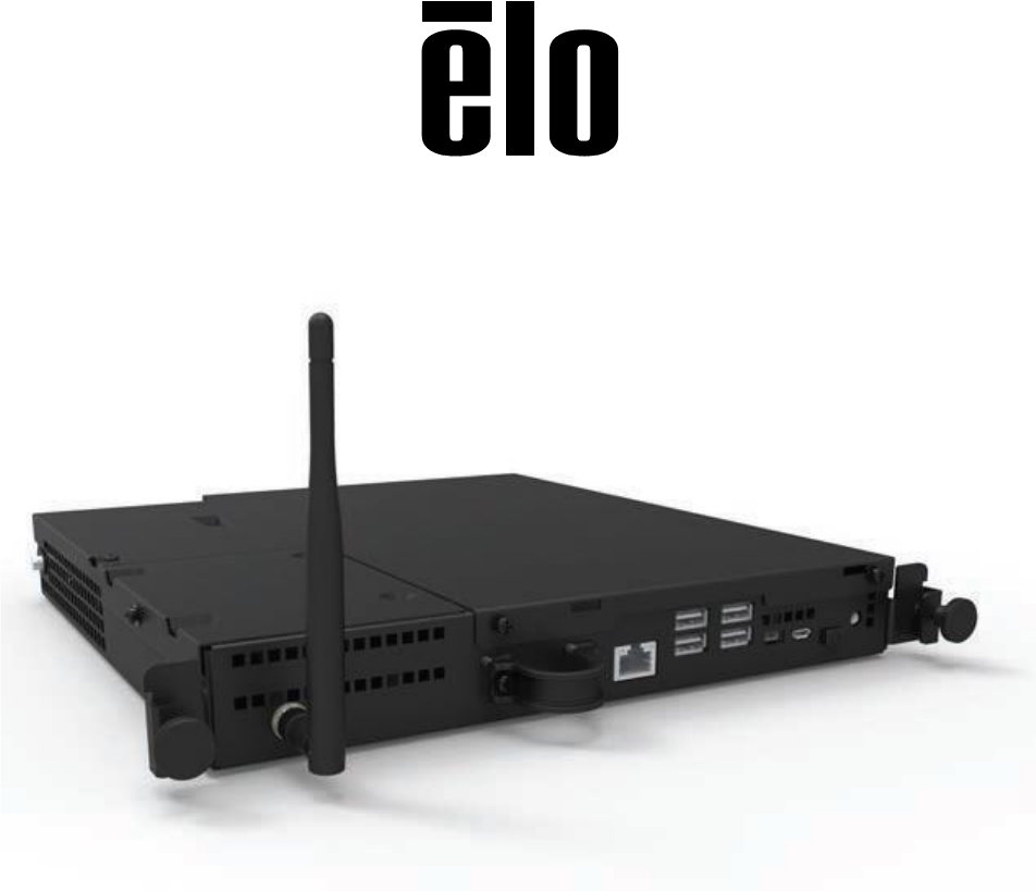
Interactive Digital Signage Android Computer Module
For
IDS 3201L/4201L/5501L/5501LT/7001L/7001LT
UM600069 Rev 01
User Guide – ELO-KIT-ECMG2-AND
UM600069 Rev A, Page 2 of 26
Copyright © 2015 Elo Touch Solutions, Inc. All Rights Reserved.
No part of this publication may be reproduced, transmitted, transcribed, stored in a retrieval system, or translated
into any language or computer language, in any form or by any means, including, but not limited to, electronic,
magnetic, optical, chemical, manual, or otherwise without prior written permission of Elo Touch Solutions, Inc.
Disclaimer
The information in this document is subject to change without notice. Elo Touch Solutions, Inc. and its affiliates
(collectively "Elo") makes no representations or warranties with respect to the contents herein, and specifically
disclaims any implied warranties of merchantability or fitness for a particular purpose. Elo reserves the right to
revise this publication and to make changes from time to time in the content hereof without obligation of Elo to
notify any person of such revisions or changes.
Trademark Acknowledgments
AccuTouch, CarrollTouch, Elo (logo), Elo Touch Solutions, Elo TouchSystems, IntelliTouch, iTouch are trademarks of
Elo and its Affiliates. Windows is a trademark of Microsoft Corporation.
User Guide – ELO-KIT-ECMG2-AND
UM600069 Rev A, Page 3 of 26
Table of Contents
Chapter 1 - Introduction ........................................................................... 4
Chapter 2 – Unpacking .............................................................................. 5
Chapter 3 – Computer Module Installation ........................................ 6
Chapter 4 – Technical Support ............................................................... 17
Chapter 5 – Safety & Maintenance ........................................................ 18
Chapter 6 – Regulatory Information ................................................... 20
Chapter 7 – Warranty ............................................................................... 26

User Guide – ELO-KIT-ECMG2-AND
UM600069 Rev A, Page 4 of 26
Chapter 1 - Introduction
Product Description
The Android Interactive Digital Signage Computer Module (AECMG) is designed to slide into
the bay on the rear of the Interactive Digital Signage Generation 2 (IDS 01) touchmonitors,
without any effect on the monitor’s form factor or requiring any extra cabling, turning your
Interactive Digital Signage TouchMonitor into an Interactive Digital Signage All-In-One
TouchComputer.
Precautions
Follow all warnings, precautions and maintenance as recommended in this user’s manual to
maximize the life of your unit and prevent risks to user safety.
This manual contains information that is important for the proper setup and maintenance of the
Computer Module. Before setting up and powering on your new computer module, read through
this manual, especially the Computer Module Installation chapter.

User Guide – ELO-KIT-ECMG2-AND
UM600069 Rev A, Page 5 of 26
Chapter 2 – Unpacking
Unpacking the Digital Signage Computer Module
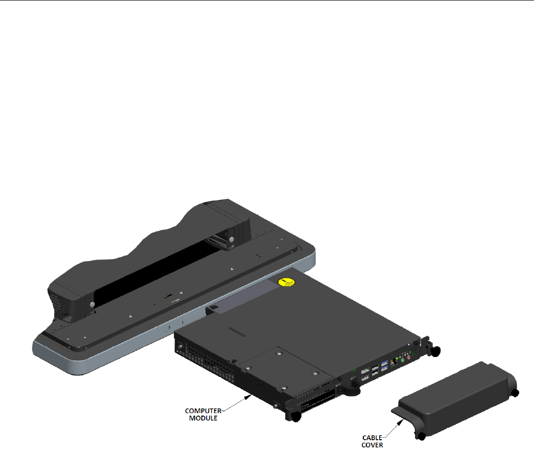
Check that the following items are present and in good condition:
Computer Module
Quick Install Guide
PC Box Cable Cover
User Guide – ELO-KIT-ECMG2-AND
UM600069 Rev A, Page 6 of 26
Chapter 3
Computer Module Installation
Installation
1. Use a Phillips head screwdriver to remove the access cover plate on the back of the
touchmonitor.
2. Slide the Computer Module all the way into the bay until it snaps into place.
3. Tighten the thumbscrews to secure the computer module inside the bay.
NOTE: If any cables are connected to the computer module, a cable security cover is
included with the computer module kit. Install it by attaching the mounting clip and bracket as
shown in the user guide for the computer module and then fastening the thumbscrews on the
cover.
User Guide – ELO-KIT-ECMG2-AND
UM600069 Rev A, Page 7 of 26
Connector Panel & Interfaces
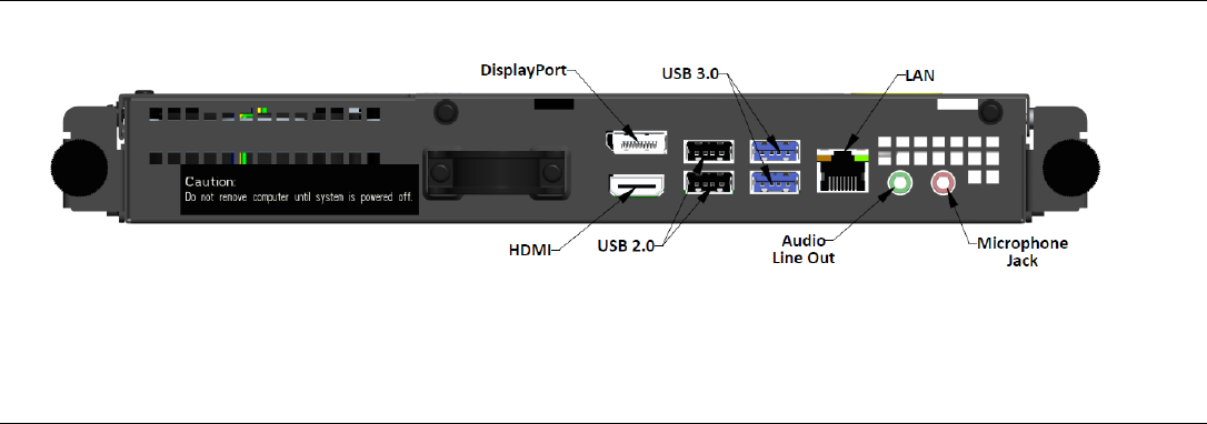
Touchmonitor & Computer Module Connections
1. Once the Computer Module has been installed, connect the AC power cable between
the touchmonitor’s POWER IN connector and the AC power source.
NOTE: Computer Module can be installed when the AC power cable is connected (Hot
pluggable). Do not remove the computer module unless it is completely shut off.
2. Make any desired connections to the Computer Module connector panel.
3. Press the touchmonitor’s power button to turn on the Computer Module.
User Guide – ELO-KIT-ECMG2-AND
UM600069 Rev A, Page 8 of 26
Operating System Setup – Android
Android version 4.4 will be pre-loaded on the system.
Gesturing Images:
For multi-touch monitors, the following gestures are possible:
Dual Touch Gestures and their Functions:
Swipe – The action of moving a finger across the screen.
- The ability to swipe through from one picture to another or drag an icon
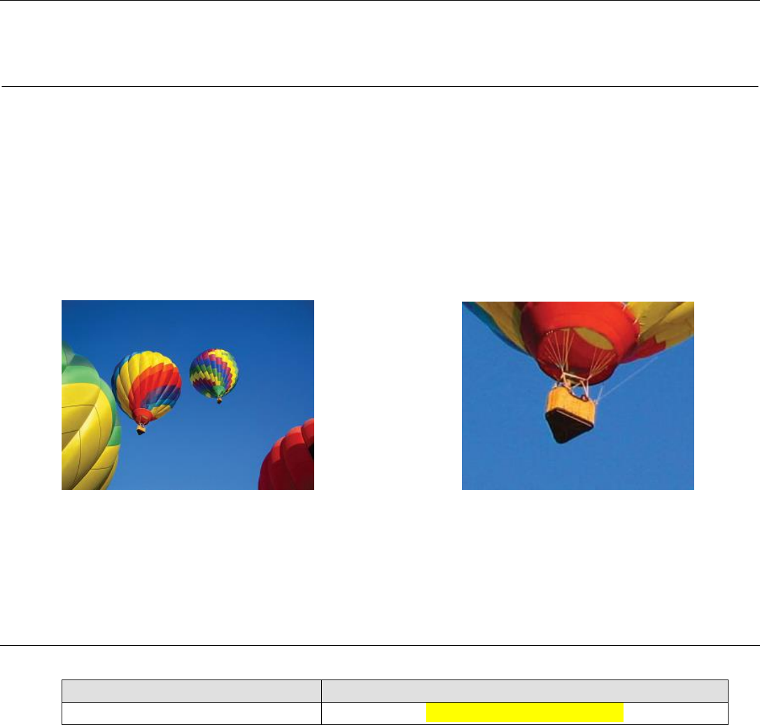
Pinch-Zoom – Zoom into a picture
- Place two fingers on the screen and move them closer together to zoom in. Move your
fingers away from each other to zoom out.
Before zoom After zoom
For Optical Monitors:
- If multi touch is required, contact Elo Customer Service for the process to enable six
simultaneous touches.
Physical Button Functionality
Parameter
Available Adjustment
Home Button
Returns to the Home page
User Guide – ELO-KIT-ECMG2-AND
UM600069 Rev A, Page 9 of 26
Audio
Earphone output with microphone input is supported.
Note: If Bluetooth speakers are used, ensure that the speakers are not placed directly in front of
the monitor. This can cause interference and disrupt your listening experience.
Wifi + Bluetooth
The following protocols are supported for Wifi and Bluetooth:
Bluetooth 4.0+EDR Class 2, A2DP/ HID (Keyboard/Mouse), SPP (printer), Barcode scanner
(HID/SPP) support.
IEEE 802.11b/g/n; WEP/WPA/WPA2 capable
iBeacon capable
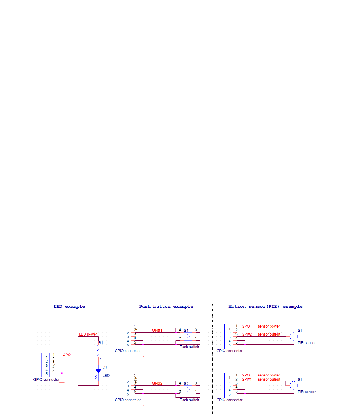
General Purpose Input/Output (GPIO) Support
The AECM supports a GPIO which can be used under the following conditions:
Max Voltage: 5V
Max Current: 200mA
There are two input connections and one output connection.
Pin 1 5 Volt output connection
Pin 2 Input connection 1
Pin 3 Input connection 2
Pin 4 and Pin 5 are tied to ground
Elo has a cable (PN # E086398) which extends this GPIO connection so that it is easy for
users to connect their own peripherals. This cable can be found on the Elo website.
User Guide – ELO-KIT-ECMG2-AND
UM600069 Rev A, Page 10 of 26
Example Circuit
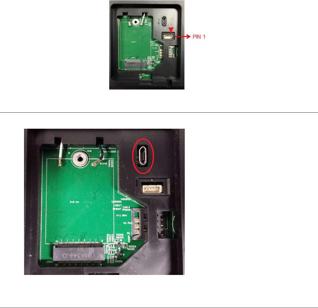
USB On The Go (OTG)
USB OTG is supported via the micro-USB connector located in the following position.
Note: Improper use of this connector can result in a broken connector.
Software Section (Download SDK from www.elotouch.com)
1. Glossary
1.1. Abbreviation
SoC: System on a chip
1.2. Terms
IDLE_MODE: ELO specification for device interaction with POWER_KEY action
MSR: Magnetic Stripe Reader
User Guide – ELO-KIT-ECMG2-AND
UM600069 Rev A, Page 11 of 26
BCR: Barcode Reader
NFC: Near Field Communication
ELOPeripheralService: The fundamental class to provide different functions for ELO
application developmentEx
2. System Overview
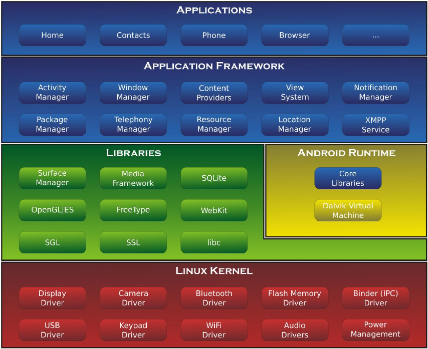
Fig 3-1 shows the software stack of Android system. This implementation based on Android
design and extends the framework functionality at java services layer to fulfill customer
requirement. The extended functionality at java service is named as “ELOPeripheralService”
which provides the interfaces for application development.
Fig 2-1. Android System Structure
2.1. Android Framework Java Service
Based on developed programming language, Android services can be divided into native (C
base) and java service. Android services are a kind of server-client structure where the server
side can receive a request from the client and output the result to client. Also, the server-client
structure can deal with synchronization issues from multi-client requests. Therefore, this
User Guide – ELO-KIT-ECMG2-AND
UM600069 Rev A, Page 12 of 26
framework ability, which forms the fundamental class “ELOPeripheralService,” is based on this
kind of server-client design feature from Android.
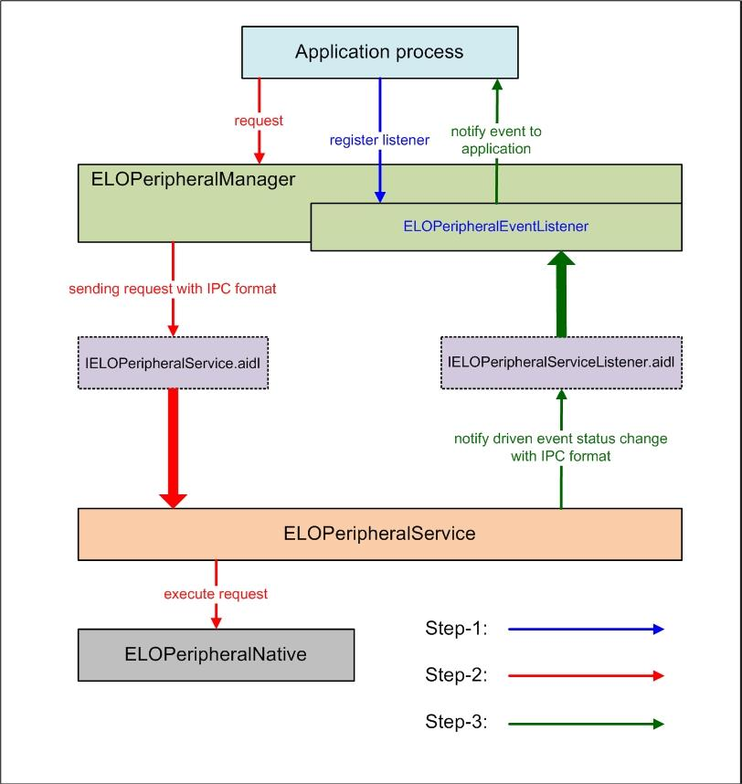
2.2. ELOPeripheralService
ELOPeripheralService is the major module to act client request from application layer. In order
to complete the Android framework system design for service then below classes is added into
system:
ELOPeripheralNative
Execution of some native-C function flows for ELOPeripheralService
ELOPeripheralManager
Provides the interface to the application layer, which is the client component relative to
ELOPeripheralService
EloPeripheralEventListener
Application extends abstract class to receive the driven event from EloPeripheralManager
Uses event driven notification method to notify the application program about the status
change
IELOPeripheralService.aidl
Android programming language for java layer IPC communication
Used for Client-Server (ELOPeripheralManager-ELOPeripheralService) IPC
communication where sending the application’s request to server side
IELOPeripheralServiceListener.aidl
Android programming language for java layer IPC communication
Used for server to notify the event driven status change to ELOPeripheralManager then
ELOPeripheralManager will notify to application layer
User Guide – ELO-KIT-ECMG2-AND
UM600069 Rev A, Page 13 of 26
Figure 2-2. ELOPeripheralService
3. ELOPeripheralManager and ELOPeripheralEventListener
As we mentioned at last section, ELOPeripheralManager and ELOPeripheralEventListener will
be the component to provide interface for application development. Therefore, we provide the
inner member data of ELOPeripheralManager and ELOPeripheralEventListener as below.
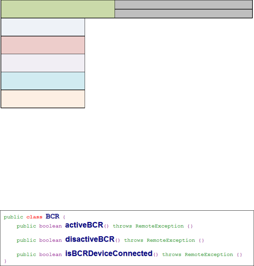
3.1. ELOPeripheralManager
Inside this manager contains some inner class member as below and for each inner class
provides specific functionality to peripheral equipment or defined action flow.
User Guide – ELO-KIT-ECMG2-AND
UM600069 Rev A, Page 14 of 26
ELOPeripheralManager
mBCR_APIs
mMSR_APIs
mNFC_APIs
mGPIO_APIs
mIDLE_APIs
public void registerListener(ELOPeripheralEventListener listener)
public void unregisterListener(ELOPeripheralEventListener listener)
public void registerListener(ELOPeripheralEventListener listener)
Provide interface for application to register the feedback structure instance
Needs to register before request (Activity life cycle: onResume)
public void unregisterListener(ELOPeripheralEventListener listener)
Provide interface for application to unregister the feedback structure instance
Needs to unregister before leave the application (Activity life cycle: onPause)
3.1.1. BCR
activeBCR
Activate the BCR device to reading the barcode data
BCR is active and successful reading the barcode sequence data then system by
“ELOPeripheralEventListener” to notify application about the receiving data
disactiveBCR
Deactivate the BCR device reading action
isBCRDeviceConnected
Check the BCR device is connection with Android device or not
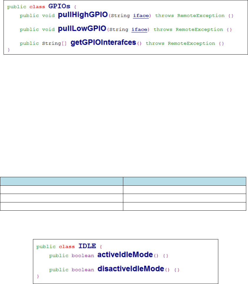
3.1.2. GPIOs
User Guide – ELO-KIT-ECMG2-AND
UM600069 Rev A, Page 15 of 26
pullHighGPIO
Pull high the state of GPIO-iface
PullLowGPIO
Pull low the state of GPIO-iface disactiveBCR
getGPIOInterfaces
Get the list string data of interest GPIOs at designed system.
Refer to Table 3-1 GPIOs list
Note:
The pull action only workable with output pin defined GPIO
The input pin defined GPIO can notify the application about the status change by
“ELOPeripheralEventListener” also
GPIOs
PIN define
gpio80
Output
gpio81
Input
gpio82
Input
Table 3-1 GPIOs List
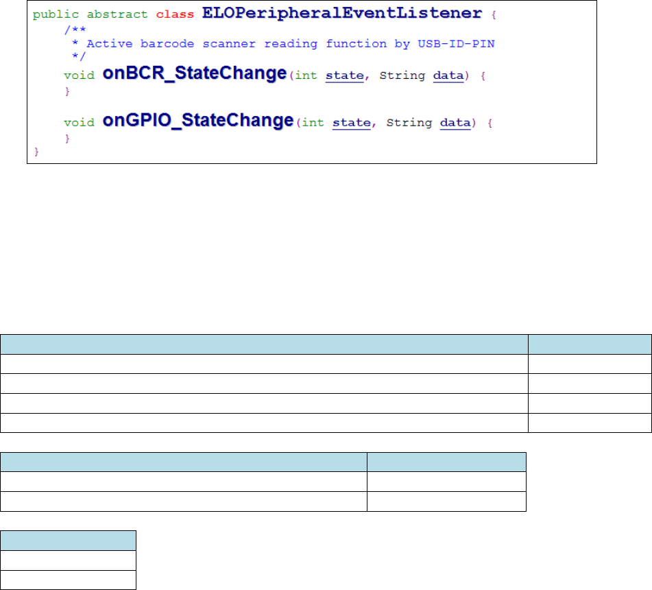
3.1.3. IDLE
activeIdleMode
Force system to enter IDLE_MODE (IDLE_MODE on)
disactiveIdleMode
Force system to leave IDLE_MODE (IDLE_MODE off)
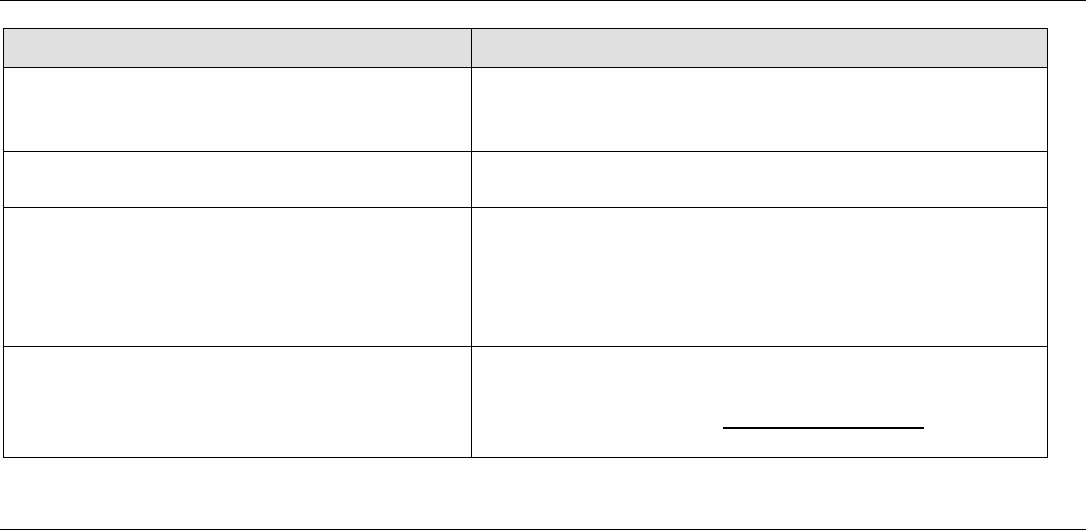
3.2. ELOPeripheralEventListener
User Guide – ELO-KIT-ECMG2-AND
UM600069 Rev A, Page 16 of 26
onBCR_StateChange
Refer to Table 3-2
Notify the application about the BCR status change data
onGPIO_StateChange
Refer to Table 3-2
Notify the application about the GPIOs status change data
BCR state
value
ELOPeripheralManager.BCR_STATE_DEVICE_CONNECTION
1 << 0
ELOPeripheralManager.BCR_STATE_DEVICE_DISCONNECTION
1 << 1
ELOPeripheralManager.BCR_STATE_DATA_RECEIVIED
1 << 2
ELOPeripheralManager.BCR_STATE_PIN_AUTO_DISABLE
1 << 3
GPIO state
value
ELOPeripheralManager.GPIO_STATE_HIGH
1 << 4
ELOPeripheralManager.GPIO_STATE_LOW
1 << 5
GPIO data
gpio81
gpio82
Table 3-2
User Guide – ELO-KIT-ECMG2-AND
UM600069 Rev A, Page 17 of 26
Chapter 4 – Technical Support
If you are experiencing trouble with your touchmonitor, refer to the following suggestions.
If the problem persists, please contact your local dealer or contact Elo Touch Solutions Customer
Service.
Solutions to Common Problems
Problem
Suggested Troubleshooting
The Computer Module does not turn on
when the power button is pressed.
Disconnect the AC power cable and verify that the
Computer Module is properly installed. Reconnect
the AC power cable and turn on the system.
Monitor display is dim
Use the OSD to increase the touchmonitor
brightness and/or contrast.
Monitor display is blank.
If the Power Status LED is blinking, the monitor or
Computer Module may be in SLEEP mode. Press
any key, move the mouse, and/or touch the
touchscreen and verify that the monitor displays
content.
Monitor displays an “Out Of Range”
message
Adjust computer resolution/timing mode to be within
the allowable timing ranges specified for the
touchmonitor. Refer to www.elotouch.com for Elo
touchmonitor specification.
Technical Assistance
Visit www.elotouch.com/go/websupport for online self-help.
Visit www.elotouch.com/go/contactsupport for technical support.
See this user manual’s last page for worldwide technical support phone numbers.
Technical assistance for Computer Modules running Windows OS are also available on the computer
in the Support Information section of the Systems Properties menu. The Systems Properties menu can
be accessed by:
1. Right-clicking the My Computer icon and selecting Properties from the drop-down menu, or
2. Clicking the Start button; go to the Settings -> Control Panel menu and selecting the System icon

User Guide – ELO-KIT-ECMG2-AND
UM600069 Rev A, Page 18 of 26
Chapter 5 – Safety & Maintenance
Safety
To avoid risk of electric shock, follow all safety notices and do not disassemble the touchmonitor
or Computer Module. They are not user-serviceable.
The slots located on the sides and top of the touchmonitor case are for ventilation. Do not block
or insert anything into the ventilation slots.
Ensure that the environmental conditions listed below are maintained for the computer module.
Environmental conditions for transportation and storage
Temperature:
Operating 0°C to 40°C
Storage/Transportation -20°C to 60°C
Humidity (non-condensing) :
Operating 20% to 80%
Sto rage/Transportation 10% to 90%
Altitude:
Operating 0 to 3,000m
Storage/Transportation 0 to 12,192m

User Guide – ELO-KIT-ECMG2-AND
UM600069 Rev A, Page 19 of 26
Caution
There is risk of explosion if battery is replaced by an incorrect type. Dispose of used batteries at the end
of its useful life according to local laws and regulations.
Waste Electrical & Electronic Equipment Directive (WEEE)
This product should not be disposed of with household waste. It should be deposited at a
facility that enables recovery and recycling. Ensure that product is disposed at the end of
its useful life according to local laws and regulations.
Elo has put in place recycling arrangements in certain parts of the world. For more
information on how you can access these arrangements, please visit
http://www.elotouch.com/AboutElo/ewaste-program/.

User Guide – ELO-KIT-ECMG2-AND
UM600069 Rev A, Page 20 of 26
Chapter 6 - Regulatory Information
I. Electrical Safety Information:
Compliance is required with respect to the voltage, frequency, and current requirements
indicated on the manufacturer’s label. Connecting a device to a power source that does not
meet requirements other than those specified herein may result in improper operation, damage
to the equipment or pose a fire hazard.
There are no operator serviceable parts inside this equipment. There are hazardous voltages
generated by this equipment which constitute a safety hazard. Service should be provided only
by a qualified service technician.
Contact a qualified electrician or the manufacturer if there are questions about the installation
prior to connecting the equipment to mains power.
II. Emissions and Immunity Information
Notice to Users in the United States:
This device complies with part 15 of the FCC Rules. Operation is subject to the following two
conditions: (1) This device may not cause harmful interference, and (2) this device must accept
any interference received, including interference that may cause undesired operation.
This equipment has been tested and found to comply with the limits for a Class A digital device,
pursuant to Part 15 of FCC Rules. These limits are designed to provide reasonable protection
against harmful interference in a residential installation. This equipment generates, uses, and
can radiate radio frequency energy, and if not installed and used in accordance with the
instructions, may cause harmful interference to radio communications. Operation of this
equipment in a residential area is likely to cause harmful interference in which case the user will
be required to correct the interference at his own expense.
FCC Caution: Any changes or modifications not expressly approved by the party responsible for
compliance could void the user's authority to operate this equipment.
This transmitter must not be co-located or operating in conjunction with any other antenna or
transmitter.
Notice to Users in Canada:

User Guide – ELO-KIT-ECMG2-AND
UM600069 Rev A, Page 21 of 26
This device complies with Industry Canada license-exempt RSS standard(s). Operation is
subject to the following two conditions:
(1) this device may not cause interference, and
(2) this device must accept any interference, including interference that may cause undesired
operation of the device.
Le présent appareil est conforme aux CNR d'Industrie Canada applicables aux appareils radio
exempts de licence. L'exploitation est autorisée aux deux conditions suivantes :
(1) l'appareil ne doit pas produire de brouillage, et
(2) l'utilisateur de l'appareil doit accepter tout brouillage radioélectrique subi, même si le
brouillage est susceptible d'en compromettre le fonctionnement.
Notice to Users in the European Union:
Use only the provided power cords and interconnecting cabling provided with the equipment.
Substitution of provided cords and cabling may compromise electrical safety or CE Mark
Certification for emissions or immunity as required by the following standards:
This Information Technology Equipment (ITE) is required to have a CE Mark on the
Manufacturer’s label which means that the equipment has been tested to the following
Directives and Standards: This equipment has been tested to the requirements for the CE Mark

User Guide – ELO-KIT-ECMG2-AND
UM600069 Rev A, Page 22 of 26
as required by EMC Directive 2004/108/EC as indicated in European Standard EN 55022 Class
A and the Low Voltage Directive 2006/95/EC as indicated in European Standard EN 60950-1.
General Information to all Users: This equipment generates, uses, and can radiate radio
frequency energy. If not installed and used according to this manual the equipment may cause
interference with radio and television communications. There is, however, no guarantee that
interference will not occur in any particular installation due to site-specific factors.
1) In order to meet emission and immunity requirements, the user must observe the following:
a) Use only the provided I/O cables to connect this digital device with any computer.
b) To ensure compliance, use only the provided manufacturer’s approved line cord.
c) The user is cautioned that changes or modifications to the equipment not expressly
approved by the party responsible for compliance could void the user’s authority to operate
the equipment.
2) If this equipment appears to cause interference with radio or television reception, or any
other device:
a) Verify as an emission source by turning the equipment off and on.
If you determine that this equipment is causing the interference, try to correct the interference
by using one or more of the following measures:
i) Move the digital device away from the affected receiver.
ii) Reposition (turn) the digital device with respect to the affected receiver.
iii) Reorient the affected receiver’s antenna.
iv) Plug the digital device into a different AC outlet so the digital device and the receiver
are on different branch circuits.
v) Disconnect and remove any I/O cables that the digital device does not
use.(Unterminated I/O cables are a potential source of high RF emission levels.)
vi) Plug the digital device into only a grounded outlet receptacle. Do not use AC adapter
plugs. (Removing or cutting the line cord ground may increase RF emission levels and
may also present a lethal shock hazard to the user.)
If you need additional help, consult your dealer, manufacturer, or an experienced radio or
television technician.

User Guide – ELO-KIT-ECMG2-AND
UM600069 Rev A, Page 23 of 26
III. Radio Frequency Exposure
Notice to Users in the United States:
FCC RF Exposure Compliance: This equipment complies with radio frequency (RF) exposure
limits adopted by the Federal Communications Commission for an uncontrolled environment.
This equipment should be installed and operated with minimum distance 20 cm between the
radiator and your body.
Notice to Users in Canada:
This equipment complies with the Class A limits for radio noise emissions from digital apparatus
as established by the Radio Interference Regulations of Industrial Canada. IC RSS-102 RF
exposure limits set forth for an uncontrolled environment. This equipment should be installed
and operated with minimum distance 20 cm between the radiator and your body.
Déclaration d'exposition aux radiations: Cet équipement est conforme aux limites d'exposition
aux rayonnements IC établies pour un environnement non contrôlé. Cet équipement doit être
installé et utilisé avec un minimum de 20 cm de distance entre la source de rayonnement et
votre corps.
CE RF Exposure Compliance:
This device meets the EU requirements (1999/519/EC) and the International Commission on
Non-Ionizing Radiation Protection (ICNIRP) on the limitation of exposure of the general public
to electromagnetic fields by way of health protection.

User Guide – ELO-KIT-ECMG2-AND
UM600069 Rev A, Page 24 of 26
IV. Agency Certifications
The following certifications and marks have been issued or declared for this monitor:
Europe CE
Canada CUL, IC
United States FCC, UL

User Guide – ELO-KIT-ECMG2-AND
UM600069 Rev A, Page 26 of 26
Check out our website
www.elotouch.com
Get the latest...
Product Information
Specifications
Upcoming events
Press releases
Software drivers
Getting in Touch with Us
To find out more about the extensive range of Elo touch solutions, visit our website at
www.elotouch.com, or simply call the office nearest you:
North America
Elo Touch Solutions
1033 McCarthy Blvd
Milpitas, CA 95035
Tel 800-ELO-TOUCH
Tel 1-408-597-8000
Fax 1-408-597-8050
customerservice@elotouch.com
Europe
Tel +32 (0) 16 70 45 00
Fax +32 (0) 16 70 45 49
elosales@elotouch.com
Asia-Pacific
Tel +86 (21) 3329 1385
Fax +86 (21) 3329 1400
www.elotouch.com.cn
Latin America
Tel 786-923-0251
Fax 305-931-0124
www.elotouch.com
Copyright 2015 Elo Touch Solutions, Inc. All rights reserved
