Elpas Solutions 5-ALC01121-0 ALC LF BUS Beacon, indoor/outdoor 125 kHz + 433 MHz User Manual Handheld LF Exciter User Guide
Elpas Solutions Ltd. ALC LF BUS Beacon, indoor/outdoor 125 kHz + 433 MHz Handheld LF Exciter User Guide
Contents
- 1. User Manual
- 2. User Manual 2
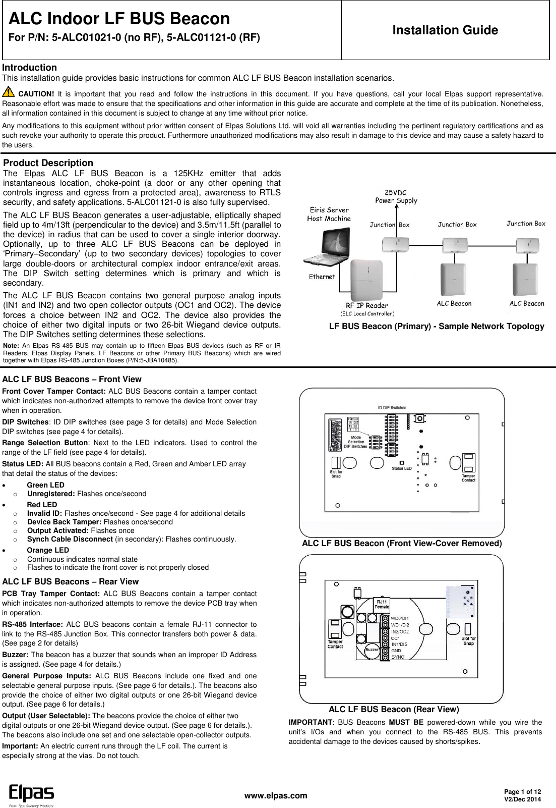
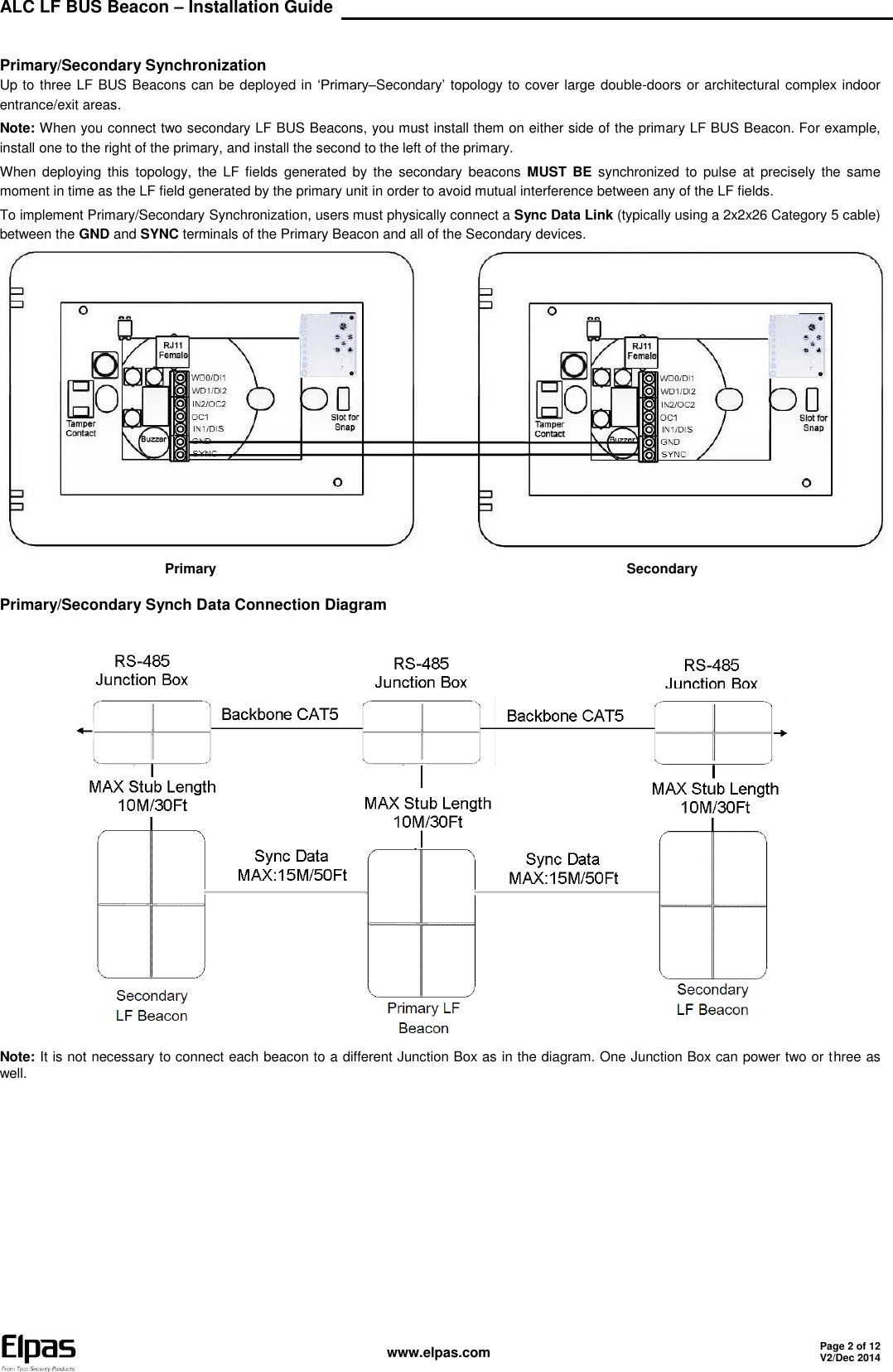
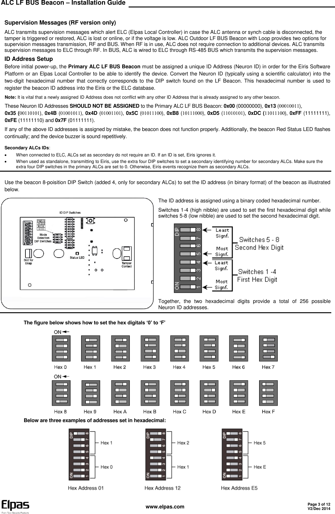
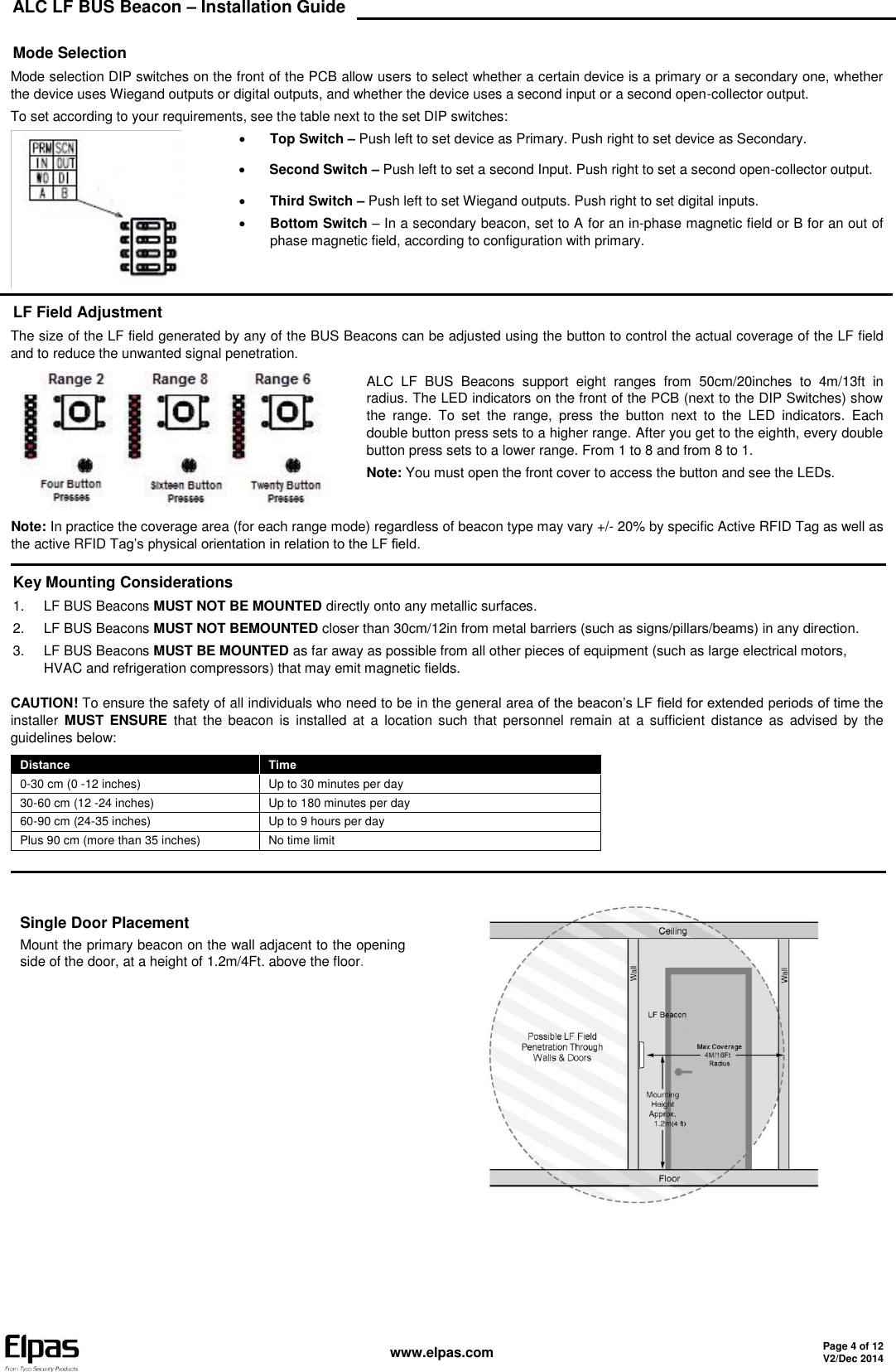
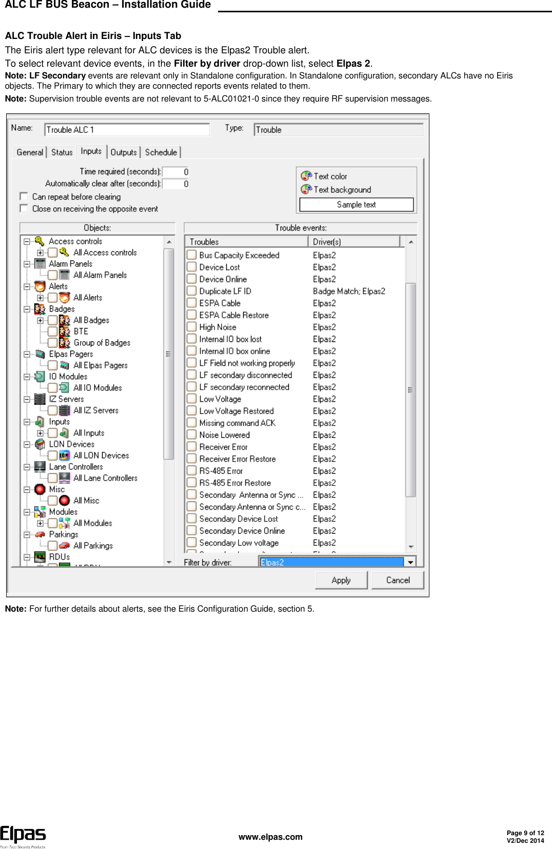
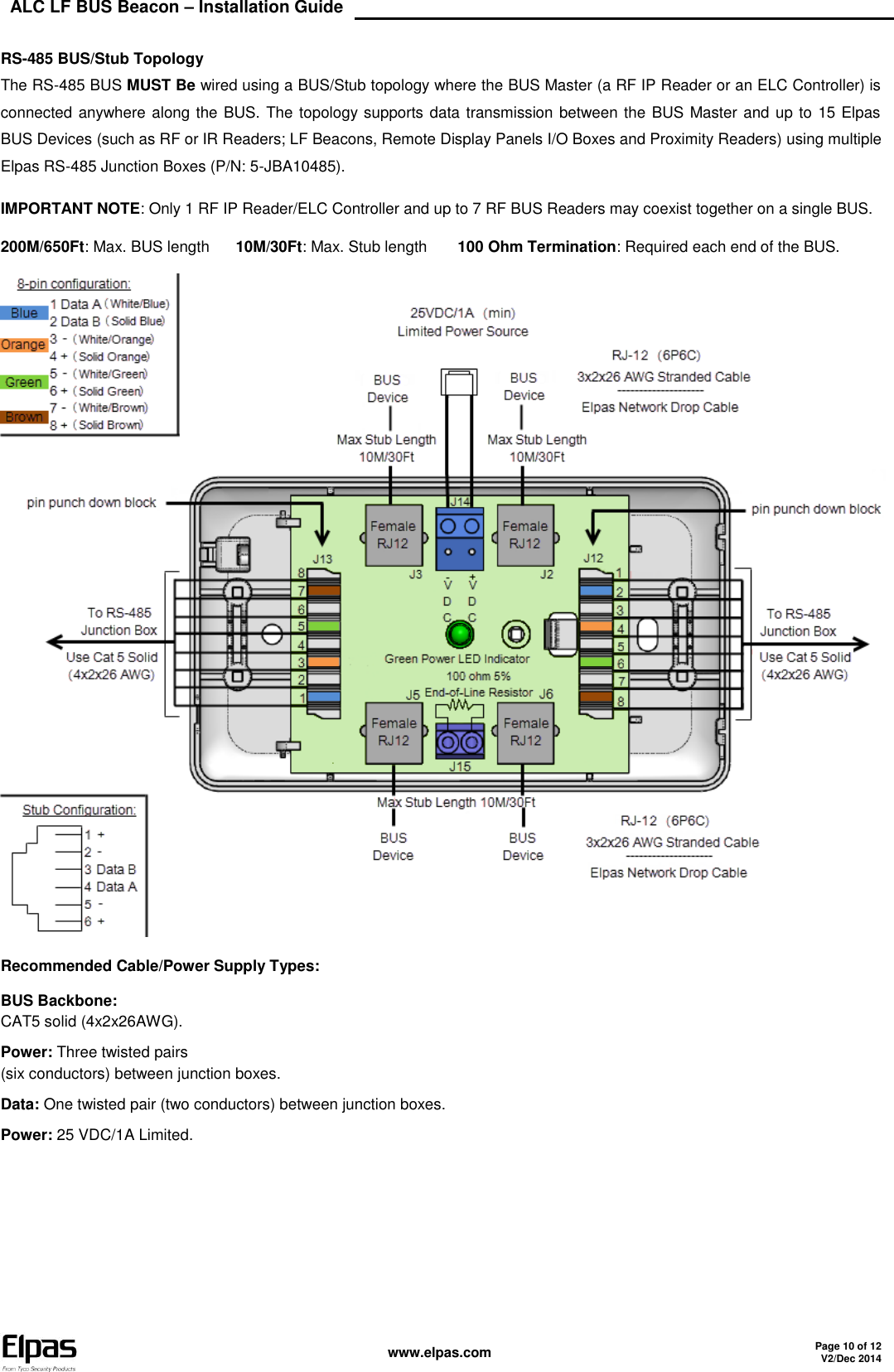
User Manual