Elpas Solutions 5-ALC01121-0 ALC LF BUS Beacon, indoor/outdoor 125 kHz + 433 MHz User Manual Handheld LF Exciter User Guide
Elpas Solutions Ltd. ALC LF BUS Beacon, indoor/outdoor 125 kHz + 433 MHz Handheld LF Exciter User Guide
Contents
- 1. User Manual
- 2. User Manual 2
User Manual
www.elpas.com
Page 1 of 12
V2/Dec 2014
ALC Indoor LF BUS Beacon
For P/N: 5-ALC01021-0 (no RF), 5-ALC01121-0 (RF)
Installation Guide
Introduction
This installation guide provides basic instructions for common ALC LF BUS Beacon installation scenarios.
CAUTION! It is important that you read and follow the instructions in this document. If you have questions, call your local Elpas support representative.
Reasonable effort was made to ensure that the specifications and other information in this guide are accurate and complete at the time of its publication. Nonetheless,
all information contained in this document is subject to change at any time without prior notice.
Any modifications to this equipment without prior written consent of Elpas Solutions Ltd. will void all warranties including the pertinent regulatory certifications and as
such revoke your authority to operate this product. Furthermore unauthorized modifications may also result in damage to this device and may cause a safety hazard to
the users.
Product Description
The Elpas ALC LF BUS Beacon is a 125KHz emitter that adds
instantaneous location, choke-point (a door or any other opening that
controls ingress and egress from a protected area), awareness to RTLS
security, and safety applications. 5-ALC01121-0 is also fully supervised.
The ALC LF BUS Beacon generates a user-adjustable, elliptically shaped
field up to 4m/13ft (perpendicular to the device) and 3.5m/11.5ft (parallel to
the device) in radius that can be used to cover a single interior doorway.
Optionally, up to three ALC LF BUS Beacons can be deployed in
‘Primary–Secondary’ (up to two secondary devices) topologies to cover
large double-doors or architectural complex indoor entrance/exit areas.
The DIP Switch setting determines which is primary and which is
secondary.
The ALC LF BUS Beacon contains two general purpose analog inputs
(IN1 and IN2) and two open collector outputs (OC1 and OC2). The device
forces a choice between IN2 and OC2. The device also provides the
choice of either two digital inputs or two 26-bit Wiegand device outputs.
The DIP Switches setting determines these selections.
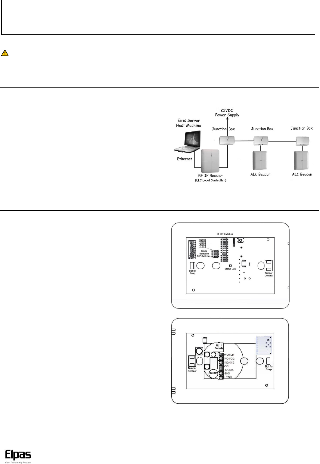
Note: An Elpas RS-485 BUS may contain up to fifteen Elpas BUS devices (such as RF or IR
Readers, Elpas Display Panels, LF Beacons or other Primary BUS Beacons) which are wired
together with Elpas RS-485 Junction Boxes (P/N:5-JBA10485).
LF BUS Beacon (Primary) - Sample Network Topology
ALC LF BUS Beacons – Front View
Front Cover Tamper Contact: ALC BUS Beacons contain a tamper contact
which indicates non-authorized attempts to remove the device front cover tray
when in operation.
DIP Switches: ID DIP switches (see page 3 for details) and Mode Selection
DIP switches (see page 4 for details).
Range Selection Button: Next to the LED indicators. Used to control the
range of the LF field (see page 4 for details).
Status LED: All BUS beacons contain a Red, Green and Amber LED array
that detail the status of the devices:
Green LED
o Unregistered: Flashes once/second
Red LED
o Invalid ID: Flashes once/second - See page 4 for additional details
o Device Back Tamper: Flashes once/second
o Output Activated: Flashes once
o Synch Cable Disconnect (in secondary): Flashes continuously.
Orange LED
o Continuous indicates normal state
o Flashes to indicate the front cover is not properly closed
ALC LF BUS Beacons – Rear View
PCB Tray Tamper Contact: ALC BUS Beacons contain a tamper contact
which indicates non-authorized attempts to remove the device PCB tray when
in operation.
RS-485 Interface: ALC BUS beacons contain a female RJ-11 connector to
link to the RS-485 Junction Box. This connector transfers both power & data.
(See page 2 for details)
Buzzer: The beacon has a buzzer that sounds when an improper ID Address
is assigned. (See page 4 for details.)
General Purpose Inputs: ALC BUS Beacons include one fixed and one
selectable general purpose inputs. (See page 6 for details.). The beacons also
provide the choice of either two digital outputs or one 26-bit Wiegand device
output. (See page 6 for details.)
Output (User Selectable): The beacons provide the choice of either two
digital outputs or one 26-bit Wiegand device output. (See page 6 for details.).
The beacons also include one set and one selectable open-collector outputs.
Important: An electric current runs through the LF coil. The current is
especially strong at the vias. Do not touch.
ALC LF BUS Beacon (Front View-Cover Removed)
ALC LF BUS Beacon (Rear View)
IMPORTANT: BUS Beacons MUST BE powered-down while you wire the
unit’s I/Os and when you connect to the RS-485 BUS. This prevents
accidental damage to the devices caused by shorts/spikes.
ALC LF BUS Beacon – Installation Guide
www.elpas.com
Page 2 of 12
V2/Dec 2014
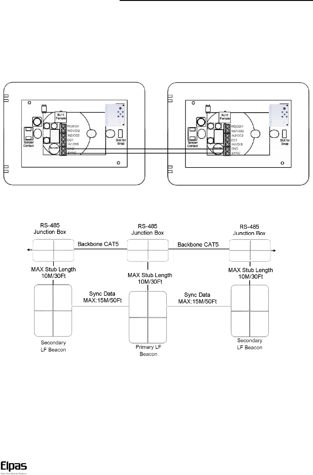
Primary/Secondary Synchronization
Up to three LF BUS Beacons can be deployed in ‘Primary–Secondary’ topology to cover large double-doors or architectural complex indoor
entrance/exit areas.
Note: When you connect two secondary LF BUS Beacons, you must install them on either side of the primary LF BUS Beacon. For example,
install one to the right of the primary, and install the second to the left of the primary.
When deploying this topology, the LF fields generated by the secondary beacons MUST BE synchronized to pulse at precisely the same
moment in time as the LF field generated by the primary unit in order to avoid mutual interference between any of the LF fields.
To implement Primary/Secondary Synchronization, users must physically connect a Sync Data Link (typically using a 2x2x26 Category 5 cable)
between the GND and SYNC terminals of the Primary Beacon and all of the Secondary devices.
Primary Secondary
Primary/Secondary Synch Data Connection Diagram
Note: It is not necessary to connect each beacon to a different Junction Box as in the diagram. One Junction Box can power two or three as
well.
ALC LF BUS Beacon – Installation Guide
www.elpas.com
Page 3 of 12
V2/Dec 2014
Supervision Messages (RF version only)
ALC transmits supervision messages which alert ELC (Elpas Local Controller) in case the ALC antenna or synch cable is disconnected, the
tamper is triggered or restored, ALC is lost or online, or if the voltage is low. ALC Outdoor LF BUS Beacon with Loop provides two options for
supervision messages transmission, RF and BUS. When RF is in use, ALC does not require connection to additional devices. ALC transmits
supervision messages to ELC through RF. In BUS, ALC is wired to ELC through RS-485 BUS which transmits the supervision messages.
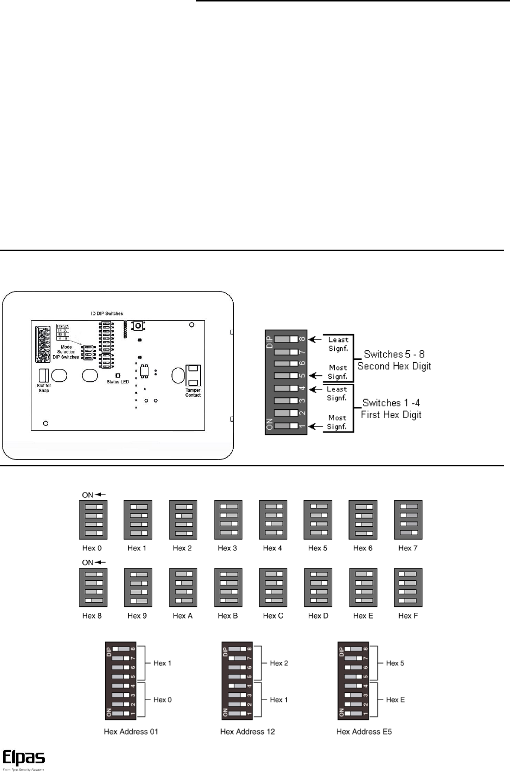
ID Address Setup
Before initial power-up, the Primary ALC LF BUS Beacon must be assigned a unique ID Address (Neuron ID) in order for the Eiris Software
Platform or an Elpas Local Controller to be able to identify the device. Convert the Neuron ID (typically using a scientific calculator) into the
two-digit hexadecimal number that correctly corresponds to the DIP switch found on the LF Beacon. This hexadecimal number is used to
register the beacon ID address into the Eiris or the ELC database.
Note: It is vital that a newly assigned ID Address does not conflict with any other ID Address that is already assigned to any other beacon.
These Neuron ID Addresses SHOULD NOT BE ASSIGNED to the Primary ALC LF BUS Beacon: 0x00 (00000000), 0x13 (00010011),
0x35 (00110101), 0x4B (01001011), 0x4D (01001101), 0x5C (01011100), 0xB8 (10111000), 0xD5 (11010101), 0xDC (11011100), 0xFF (11111111),
0xFE (11111110) and 0x7F (01111111).
If any of the above ID addresses is assigned by mistake, the beacon does not function properly. Additionally, the beacon Red Status LED flashes
continually; and the device buzzer is sound repetitively.
Secondary ALCs IDs:
When connected to ELC, ALCs set as secondary do not require an ID. If an ID is set, Eiris ignores it.
When used as standalone, transmitting to Eiris, use the extra four DIP switches to set a secondary identifying number for secondary ALCs. Make sure the
extra four DIP switches in the primary ALCs are set to 0. Otherwise, Eiris events recognize them as secondary ALCs.
Use the beacon 8-poisition DIP Switch (added 4, only for secondary ALCs) to set the ID address (in binary format) of the beacon as illustrated
below.
The ID address is assigned using a binary coded hexadecimal number.
Switches 1-4 (high nibble) are used to set the first hexadecimal digit while
switches 5-8 (low nibble) are used to set the second hexadecimal digit.
Together, the two hexadecimal digits provide a total of 256 possible
Neuron ID addresses.
The figure below shows how to set the hex digitals ‘0’ to ‘F’
Below are three examples of addresses set in hexadecimal:
ALC LF BUS Beacon – Installation Guide
www.elpas.com
Page 4 of 12
V2/Dec 2014
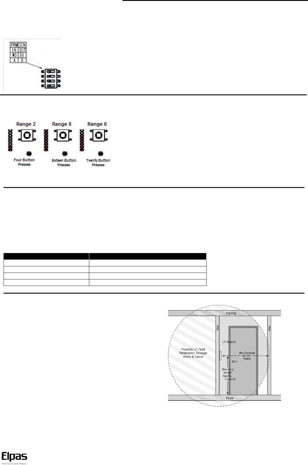
Mode Selection
Mode selection DIP switches on the front of the PCB allow users to select whether a certain device is a primary or a secondary one, whether
the device uses Wiegand outputs or digital outputs, and whether the device uses a second input or a second open-collector output.
To set according to your requirements, see the table next to the set DIP switches:
Top Switch – Push left to set device as Primary. Push right to set device as Secondary.
Second Switch – Push left to set a second Input. Push right to set a second open-collector output.
Third Switch – Push left to set Wiegand outputs. Push right to set digital inputs.
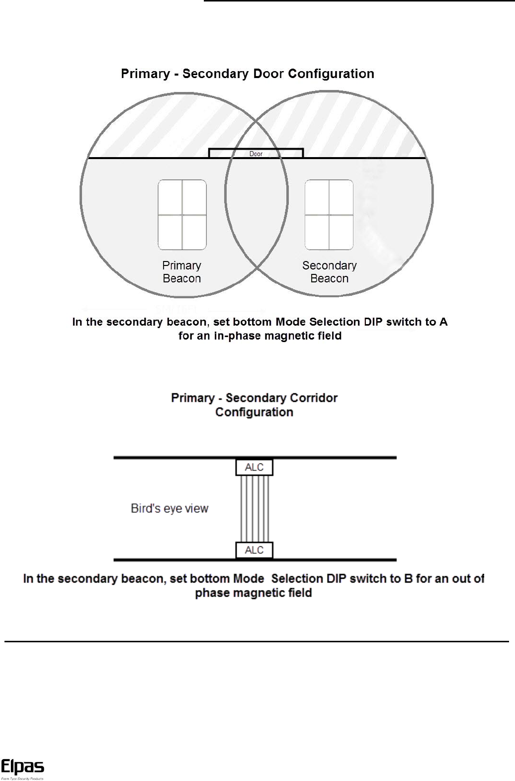
Bottom Switch – In a secondary beacon, set to A for an in-phase magnetic field or B for an out of
phase magnetic field, according to configuration with primary.
LF Field Adjustment
The size of the LF field generated by any of the BUS Beacons can be adjusted using the button to control the actual coverage of the LF field
and to reduce the unwanted signal penetration.
ALC LF BUS Beacons support eight ranges from 50cm/20inches to 4m/13ft in
radius. The LED indicators on the front of the PCB (next to the DIP Switches) show
the range. To set the range, press the button next to the LED indicators. Each
double button press sets to a higher range. After you get to the eighth, every double
button press sets to a lower range. From 1 to 8 and from 8 to 1.
Note: You must open the front cover to access the button and see the LEDs.
Note: In practice the coverage area (for each range mode) regardless of beacon type may vary +/- 20% by specific Active RFID Tag as well as
the active RFID Tag’s physical orientation in relation to the LF field.
Key Mounting Considerations
1. LF BUS Beacons MUST NOT BE MOUNTED directly onto any metallic surfaces.
2. LF BUS Beacons MUST NOT BEMOUNTED closer than 30cm/12in from metal barriers (such as signs/pillars/beams) in any direction.
3. LF BUS Beacons MUST BE MOUNTED as far away as possible from all other pieces of equipment (such as large electrical motors,
HVAC and refrigeration compressors) that may emit magnetic fields.
CAUTION! To ensure the safety of all individuals who need to be in the general area of the beacon’s LF field for extended periods of time the
installer MUST ENSURE that the beacon is installed at a location such that personnel remain at a sufficient distance as advised by the
guidelines below:
Distance
Time
0-30 cm (0 -12 inches)
Up to 30 minutes per day
30-60 cm (12 -24 inches)
Up to 180 minutes per day
60-90 cm (24-35 inches)
Up to 9 hours per day
Plus 90 cm (more than 35 inches)
No time limit
Single Door Placement
Mount the primary beacon on the wall adjacent to the opening
side of the door, at a height of 1.2m/4Ft. above the floor.
ALC LF BUS Beacon – Installation Guide
www.elpas.com
Page 5 of 12
V2/Dec 2014
Door Primary – Secondary Placement
A primary/secondary configuration may be installed by mounting the primary and secondary beacons on opposite sides of the door, at
a height of 1.2m/4Ft above the floor. The resulting LF fields are automatically synchronized in real time to avoid problems associated
with coverage area overlap.
Corridor Primary – Secondary Placement
A primary/secondary configuration may be installed by mounting the primary and secondary beacons on opposite sides of the
corridor, at a height of 1.2m/4Ft above the floor. The result is a uniform LF field between them that provides full coverage.
Note: In the primary beacon, there is no need to set the bottom Mode Selection DIP switch.
Note: For a primary with two secondary beacons configuration, contact Elpas Support.
ALC LF BUS Beacon – Installation Guide
www.elpas.com
Page 6 of 12
V2/Dec 2014
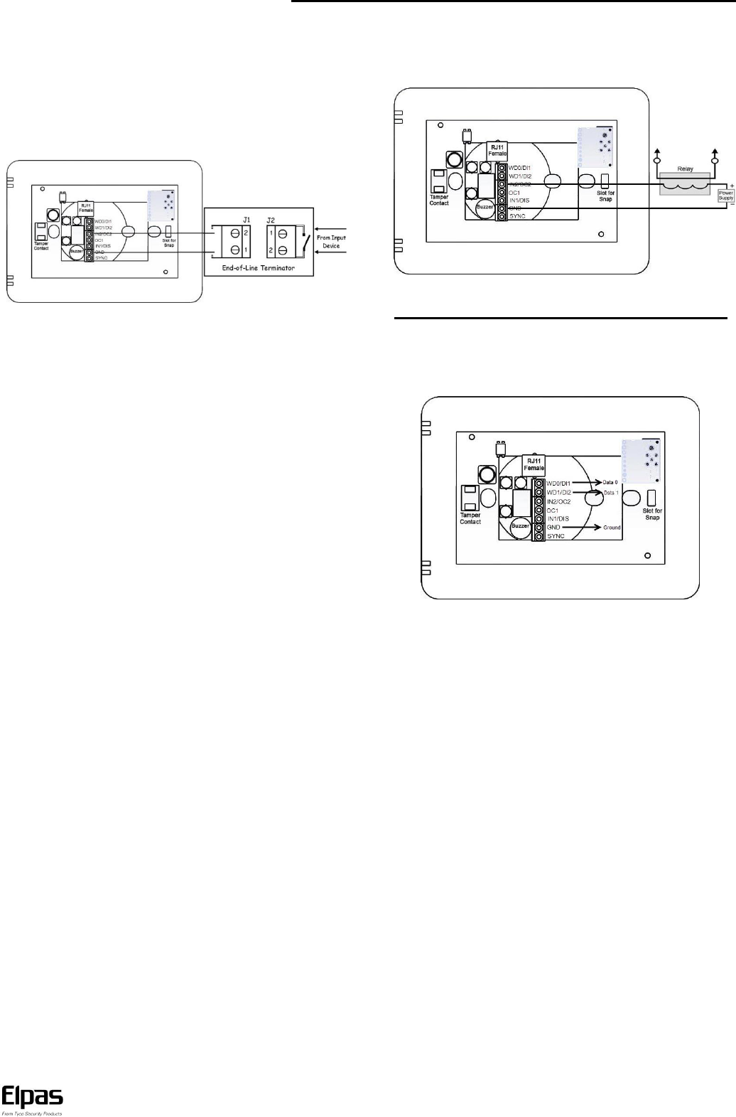
General Purpose Inputs
The beacons have two digital inputs (can be selected as a
Wiegand output). The beacons also include two general purpose
dry contact analog inputs (N.O.) for monitoring alert sensors or
emergency call buttons. They are designated as IN1 and IN2
(can be set as open-collector- output2).
EOL supervision may be added to either of these inputs to detect:
Open, Close, Line Cut, and Line Short circuit conditions using
optional Elpas End-of-Line Terminators (P/N: 5-IOX00001).
Recommended Cable: 22 AWG, unshielded/twisted pair.
Transmission Suppression Option
Input1 on all BUS Beacons may be used to disable the LF field by
shorting IN1 with GND. This allows the user to temporarily
override the beacon with a security detector, such as a door
position reed switch, which can disable the LF field as long as the
door is shut.
However IN1 can be used as a normal general purpose input
when an Elpas End-of-Line Terminator, (P/N: 5-IOX00001) is
connected to the input as illustrated in the above section.
Open-Collector Output
Both the primary beacon and the secondary beacon have two
open-collector outputs (up to 100mA, 28VDC) for actuating alert
response devices.
Note: The output is resistive loading only, there is no power factor.
Recommended Cable: 22 AWG, unshielded/twisted pair
Wiegand Output
ALC beacons provide a 26-bit Wiegand output, consisting of two
ports WD0 and WD1 (it may be enabled instead of the digital
inputs using the DIP switch) for sending Elpas tag IDs to third-
party access control panels.
Recommended Cable: 22 AWG, unshielded/twisted pair
ALC LF BUS Beacon – Installation Guide
www.elpas.com
Page 7 of 12
V2/Dec 2014
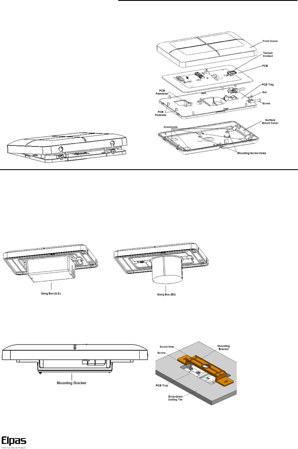
ALC LF BUS Beacon Enclosure
The ALC LF BUS Beacon enclosure is comprised of three parts: a front cover, a PCB tray, and a rear cover.
To Assemble the Enclosure:
1. Fit the PCB into the PCB tray using the pedestal (the side with
the respective white markings fits into the pedestal).
2. Make sure the nuts are in their appropriate slots.
3. Cut open trunking knockouts and thread wiring to the PCB
terminals.
4. Fit the PCB tray into the rear cover and close with the front
cover.
Note: To remove PCB, push the PCB fastener and remove
PCB.
5. Insert screws to lock.
Note: To open the enclosure, do not remove the screws. Rotate until
the head of each screw is not aligned with the cover, and slide the
front cover over the screws.
Mounting Options
ALC LF BUS Beacon allows three types of mounting: a surface mount, a flush mount, and a drop-down ceiling mount.
Surface Mount
1. Before you place the front cover, insert two screws through the PCB tray and rear cover.
2. Insert screws to the wall.
3. When properly mounted, place the front cover.
Flush Mount
1. Before you place the front cover, insert two screws through the PCB tray. Do not assemble the rear cover.
2. When properly mounted, place the front cover.
Drop-down Ceiling Mount
1. Cut a rectangle hole in the drop-down ceiling tile to accommodate the part that protrudes from the PCB tray.
2. Before you place the front cover, insert two screws through the PCB tray. Do not assemble the rear cover.
3. Align a mounting bracket and the ALC LF BUS Beacon, one on each side of the panel, and insert screws through the panel and the
mounting bracket.
4. When properly mounted, place the front cover.
ALC LF BUS Beacon – Installation Guide
www.elpas.com
Page 8 of 12
V2/Dec 2014
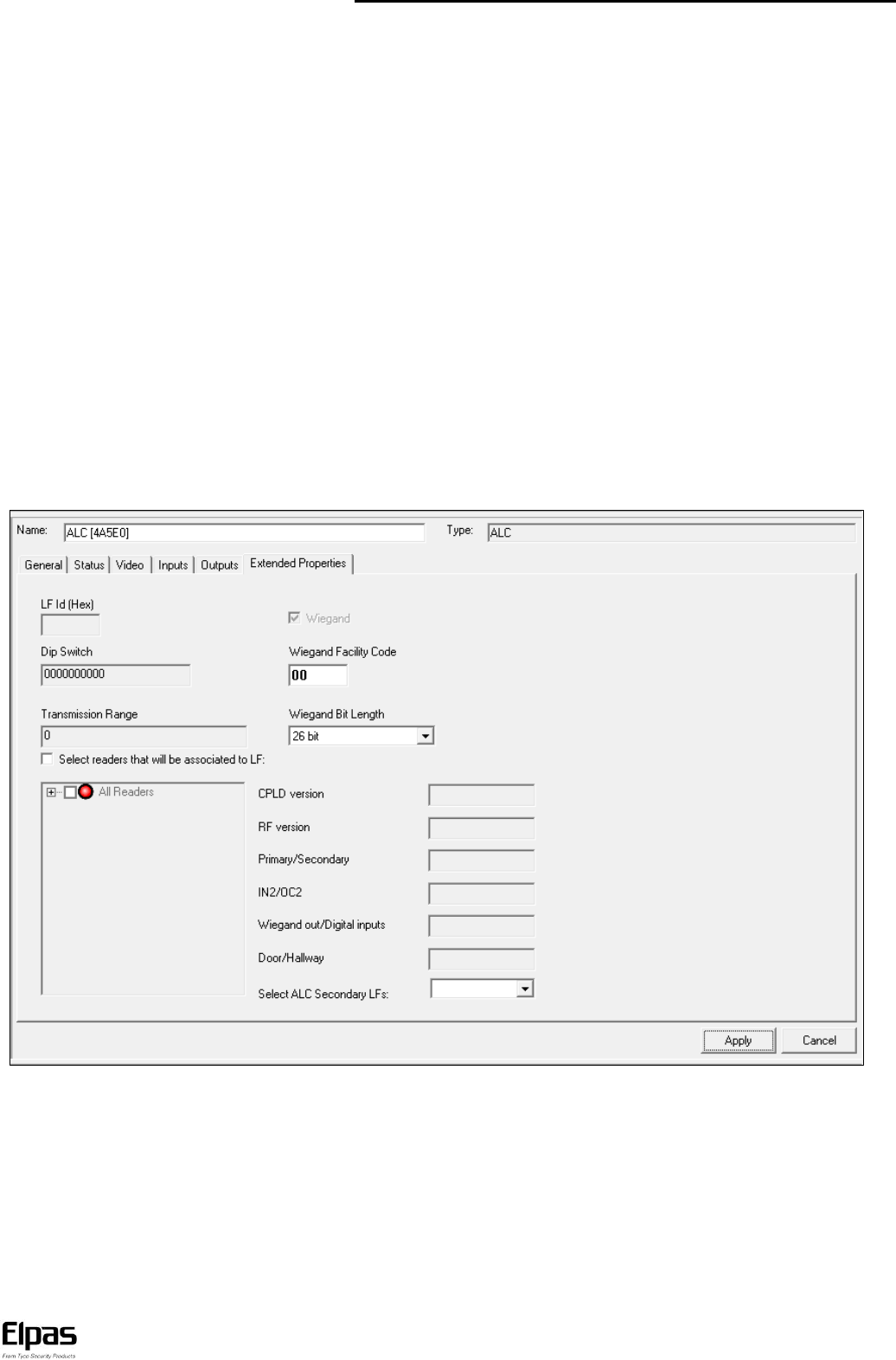
Extended Properties in ALC Eiris Object
The ALC Extended Properties tab allows users to see how the optional settings of the device are set. The Extended
Properties tab also allows users to select readers to be associated with ALC.
LF Id (Hex) field: Displays the hexadecimal representation of the set LF ID.
Dip Switch field: Displays the binary representation of the set LF ID. 1 represents a DIP switch set as ON, o represents a DIP switch set
as off.
Wiegand check-box: Selected when the top two input terminal are set as Wiegand.
Wiegand Facility Code field: Enter the Facility Code programmed into the Wiegand device.
Transmission Range field: Displays the set LF range level.
Wiegand Bit Length drop-down list: Select the Wiegand bit length.
Select readers that will be associated to LF: Select to enable reader selection. The readers list opens and allows you to select readers
to be associated with the ALC represented by this object.
CPLD version field: Displays the current CPLD firmware file.
RF version field: Displays the current RF firmware file.
Note: When you update the firmware in the General tab, notice there are two bin files. One for the CPLD, and one for the RF. The file
name indicates for which component it is. Update both files.
Primary/Secondary field: Displays whether the ALC is set as Primary or Secondary.
IN2/OC2 field: Displays whether the ALC third terminal is set as input 2 or O.C. output 2.
Wiegand out/Digital inputs field: displays whether the top two terminal blocks are set as two digital inputs or as one Wiegand output.
Door/Hallway field: Displays whether the ALC is set to be in Primary-Secondary door or hallway configuration (on the PCB, marked as A
or B, respectively).
Note: Select ALC Secondary LFs is not relevant for ALC with no RF (5-ALC010210).
ALC LF BUS Beacon – Installation Guide
www.elpas.com
Page 9 of 12
V2/Dec 2014
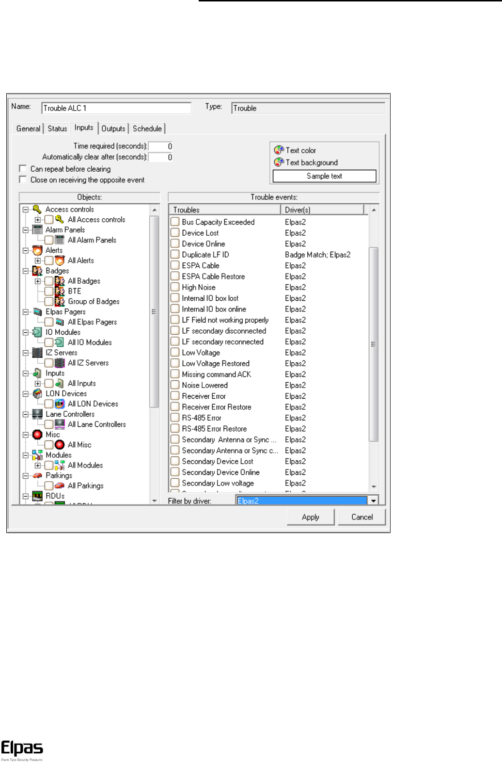
ALC Trouble Alert in Eiris – Inputs Tab
The Eiris alert type relevant for ALC devices is the Elpas2 Trouble alert.
To select relevant device events, in the Filter by driver drop-down list, select Elpas 2.
Note: LF Secondary events are relevant only in Standalone configuration. In Standalone configuration, secondary ALCs have no Eiris
objects. The Primary to which they are connected reports events related to them.
Note: Supervision trouble events are not relevant to 5-ALC01021-0 since they require RF supervision messages.
Note: For further details about alerts, see the Eiris Configuration Guide, section 5.
ALC LF BUS Beacon – Installation Guide
www.elpas.com
Page 10 of 12
V2/Dec 2014
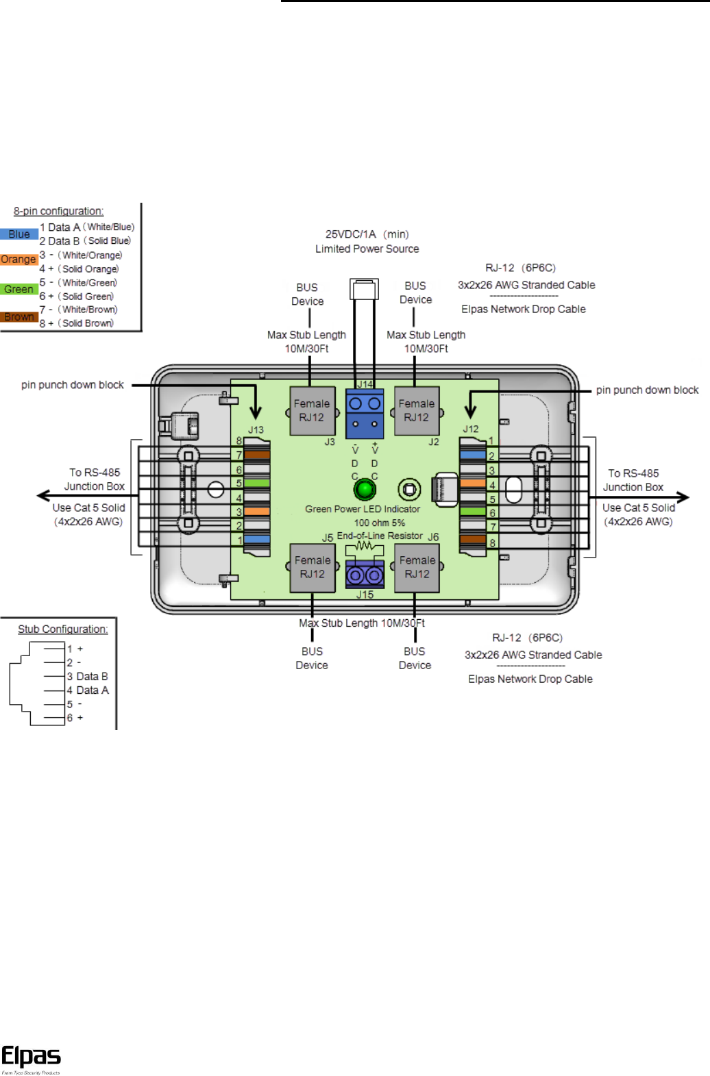
RS-485 BUS/Stub Topology
The RS-485 BUS MUST Be wired using a BUS/Stub topology where the BUS Master (a RF IP Reader or an ELC Controller) is
connected anywhere along the BUS. The topology supports data transmission between the BUS Master and up to 15 Elpas
BUS Devices (such as RF or IR Readers; LF Beacons, Remote Display Panels I/O Boxes and Proximity Readers) using multiple
Elpas RS-485 Junction Boxes (P/N: 5-JBA10485).
IMPORTANT NOTE: Only 1 RF IP Reader/ELC Controller and up to 7 RF BUS Readers may coexist together on a single BUS.
200M/650Ft: Max. BUS length 10M/30Ft: Max. Stub length 100 Ohm Termination: Required each end of the BUS.
Recommended Cable/Power Supply Types:
BUS Backbone:
CAT5 solid (4x2x26AWG).
Power: Three twisted pairs
(six conductors) between junction boxes.
Data: One twisted pair (two conductors) between junction boxes.
Power: 25 VDC/1A Limited.

ALC LF BUS Beacon – Installation Guide
www.elpas.com
Page 11 of 12
V2/Dec 2014
Product Specifications
Technology
Low frequency electromagnetic spherical shaped field (125 KHz)
Radio frequency (RF) (433 MHz) - 5-ALC01121-0 only
*Output Ranges
Eight user selectable ranges: 50cm/20 inches to 4m/13ft radius
LF Transmission Rate
Continuous bursts of LF transmissions (each about 12ms in duration)
RF Transmission Rate
Supervision messages of every 60secs - 5-ALC01121-0 only
Supervision Event Messages
3 RF transmissions (each transmission
@4ms in duration), 312.5ms apart - 5-ALC01121-0 only
Output and Format
3-byte messages (preamble, beacon ID and CRC)
Output Power
Up to 0.25mG at 1.5m/5ft
Output Bit Rate
2,000 bit per second
Electrical
Message Length
4-31 byte messages (encapsulated for messages > 4 bytes)
RS-485 BUS
230Kbit/sec
Device Supervision
Lost Away, Low Voltage, Communication Problems, Enclosure Tamper
Buzzer
Tamper: 1 second beep
Software/Controller driven
Range Indicator LEDs
The number of lit LEDs indicate the LF field range
Orange LED
Device connected and registered in Eiris or ELC: Continuous
When front cover is not properly closed: Flashes.
Can be driven remotely
Green LED
Firmware download: Flashes
Can be driven remotely
RED LED
Invalid ID Code: Flashes
Unregistered in Eiris Software: Flashes
Power up/Communication Loss: Flashes
Sync Cable Disconnect (in Secondary): Flashes
When back cover is not properly closed: Flashes
Can be driven remotely
ID Code
Set by an onboard, 8 -position DIP switch
Input/Outputs
Two N.O. dry contact analog inputs, one optional: Transmission suppression through input and the other optional output
Two optional digital inputs (rated 100mA/12VDC)…..Two optional Outputs: One 26-bit Wiegand device
Two dry contact open-collector outputs, one fixed and the other optional
Input Supervision
4 Levels (Open, Closed, Line Short, Line Cut) using optional Elpas End-of-Line Terminator
Power Requirements
12–28Vdc, 55mA @ 24VDC, 500mA max Approved limited power supply
General
Construction
White ABS plastic
Dimensions (H x W x D)
130.2 X 175.1 X 28.75 mm (5.1 X 6.9 X 1.1 inches)
Weight
306.44 grams (10.36 oz)
Tamper Protection
Two contacts, between the PCB and the front cover and the PCB tray
Device Interfaces
RS-485 Bus & Power: One Female RJ-11 (6P6C) connector
Supervised Input: Two–Position terminal block…….Digital Output: Two–Position terminal block
Primary/Secondary Output Field Synch: Two–Position terminal block
Optional 26 bit Wiegand Outputs: Two–Position terminal block
Operating Environment
Temp: -30°C to 60°C (-22°F to 140°F); Humidity: 20% to 80% non-condensing
Management Software
Eiris 4.9.1 (or higher) Software
Regulatory
CE, FCC, IC compliant
Warranty
1 year limited
* The output range (for each range mode) may vary +/- 20% by specific Active RFID Tag as well as the tag’s physical orientation in relation to the LF field and
various environmental factors including structural interference. Specifications are subject to change without notice.
Ordering Information
Part Number
Description
5-ALC010210
ALC LF BUS Beacon
5-ALC01121-0
ALC LF BUS Beacon - RF
5-IOX00001
End-of-Line Terminator for Elpas & AXS Inputs (5 units)
5-JBA10485
RS-485 Junction Box, 4 RJ11 Ports
5-LFM00125
LF Field Meter
Accessories
Part Number
Description
5-ERS02721
Network Drop Cable, 2.5 Meters/8.0 Feet
5-ERS02721-1
Network Drop Cable, 5.0 Meters/16.0 Feet
5-ERS02800
P60 Power Supply, 24VDC/2.2A
5-ALC90001
LF Mounting Bracket (set of 5)

ALC LF BUS Beacon – Installation Guide
Page 12 of 12
V2/Dec 2014
W.E.E.E. Product Recycling Declaration
For information regarding the recycling of this product you must contact the company from which you orignially purchased it.
If you are discarding this product and not returning it for repair then you must ensure that it is returned as identified by your supplier.
This product is not to be thrown away with everyday waste - Directive 2002/96/EC Waste Electrical and Electronic Equipment.
Compliance with Standards
This dev ice compli e s wit h FCC Rul es Par t 15 a n d with I ndust ry C a na da li cense exe m pt
RSS standard( s). O pe r ati o n i s subj ect t o t wo c onditio n s:
(1) T hi s dev ice may not cause harmf u l interf erence
(2) T his dev i c e m ust ac cept any inter f erence that m ay be receiv e d or that may cause
undesi red op erati o n.
Le présent a p p a r ei l e st c o n f orme aux C NR d'I ndust rie C an ada applica bl e s a ux appareil s
rad i o exempt s de li c e n c e. L'expl oi t at i o n est aut ori sée aux deux con di t i ons suiv a nte s :
(1) l 'appareil n e doit pa s pr od uire de bro ui l l age, et
(2) l' utilisateur d e l'appareil doit acc e pt er tout brouill ag e r adi oélectri q ue su bi , mêm e si
le brouilla ge e st susc ept i ble d' en c ompromettre l e f onct ionnement.
NOTE: T h i s equipme nt ha s been t e st e d an d f ound t o c omply wi th t he li mits f or a Clas s
B digital dev ice, pur suant t o P a rt 15 of the FCC R ul es. The se l i mi t s are de si g n e d t o
pro v i de rea sona bl e pr ot ection a gainst har m f ul interf ere nce i n a re sid e ntial i nst al lati o n.
This equipment generat e s, u s e s and c an radiate ra di o f r equency energy and, if not
installed and u sed i n acc or d anc e wi t h th e i n str ucti o ns, m ay ca u s e harm f ul i nterf er ence
to ra di o c om m uni cations. Howev er, there is n o gu ar a nt ee t h at i nt erf erenc e will not
occ ur in a particular install ati o n . If thi s equi pment does c a use harm f ul int erf erence to
rad i o or t e l e v i sion r eception, whi ch can be d etermi ne d by turning t he equipment of f and
on, the user i s encourage d to try to c or r ect the int e rference by one or m ore of th e
foll owing measure s:
Reorient or relocate the receiving antenna.
Increase the separation between the equipment and receiver.
Connect the equipment into an outlet on a circuit different from that to which the receiver is connected.
Consult the dealer or an experienced radio/TV technician for help.
Cet é q u i p e m e n t a é t é te st é e t j u g é c o n f orm e a ux l i m i t es s ’ a p p l i q u ant à
un appareil n um éri q u e d e cl a s se B, c onf ormément à l a P a rt i e 15 des
rég l ementations d e la F C C . Ce s l i mi t es on t été él aborées p o u r o f f r i r une
pro t ection r aisonnable c ontre l e s i nter f erenc es n ui sibl e s dans u ne
installation r é sid enti l l e.
Cet équipem ent gé n è r e , ut i l i z e e t p e u t é m e t t r e d e l ’ é n e r g i e d e f r éq ue nc e
r ad i o e t , s ’ i l n ’ e st p a s i n st a l l é e t u t i l i z e c o n f o r m é m e n t a u x i n str u c t i o n s d u
fabricant, peut pr o v oquer de s interf ére nc e s dang ere u s e s pour les
c om m u n i c a t i o n s r a d i o . T o u t e f o i s, r i e n n e g ar a n t i t l ’ a b s e n c e d ’ i n t e rf é r e n c e s
dans une i nst all ati o n parti c ulié r e. Si cet é q ui p e m ent prov oque de s
interférences n ui si bles a u niv eau de l a réception r a dio ou tel evi sion, c e qui
peut étre dete rm ine par la m i se h o r s , p ui s s o u s t e n s i on d e l ’ é q u i p m e nt , v o u s
étes inv ite à ess a y er d e cor r i ge r le s int e rf erenc es e n pr egnant l es m e sur e s
sui v a nte s:
Réo ri ent e z o u d é p l a c e s l ’ a nt e n n e r é c e p t r i c e.
A ug m e n t e z l a d i s t a n c e qu i s é p a r e l ’ é q u i p e m e n t et l e r é c e p t e u r .
B ra nc h ez l ’ é q u i pe m ent à u n e p r i se d ’ u n c i r c u i t d i f f e r e nt d e c e l u i
auquel est bra nch é l e r éc epteur.
Consultez le re v endeur ou un technici an radi o/telev isi on expérim ent é
po ur o bt e n i r d e l ’ a i de.
Wa rning!
Change s or modifi c ati on s to thi s eq u i p m ent not expressly ap pr o v ed b y
the party r e s p on si ble f or compli ance (El pa s Sol uti on s Ltd. ) c oul d v oid th e
u se r ’ s a u t h o r i t y t o o p e r at e t h e e q u i p m e nt.
Europe
This equipme nt com pl i es wi t h t he RT T E r eq ui r ements - Di r e c t i v e
1999/ 5/EC of the Europ ean P a r l iament and of t he c o un c i l of 9 March
1999.
EN 300220, EN 30 14 8 9, E N 50 130- 4, E N 61000-6-3, E N 6 0 950-1.
Product Warranty
Elpas S ol uti ons, Lt d . (El pa s or t h e Com pa ny), and i t s af fili ates, w ar r a n t s it s pr od uct s (h er ei n af ter r ef er r ed t o as "t he Pr o d u c t ” ) t o b e f ree o f d ef e c t s i n m a t e r i al s a n d wor km an shi p
un de r n orm a l o p er a t i n g c o n d i t i o n s a n d u s e f or a p e r i o d o f o n e y e a r f r o m t h e d a t e o f s h i p m e n t b y E l p a s . T h e C o m p a n y ’ s obl i g a t i on s shall b e l i m ited wi t hin t he warranty period, at
its opti o n, t o r e pai r or to re pl ac e the d ef ectiv e P r o du ct o r any d e fectiv e component or pa r t th er e of . To exerci s e t hi s warranty, the p roduct m u st be ret ur n e d to the m a n ufacturer
freight prepai d a nd i nsured.
This wa r r a n t y do e s not apply t o r epairs o r replacement c a used by improper i n st allation, Pr o duct m i suse, f ailure to f oll o w i nstal l at ion or operati ng in st r u c t i ons, alte r ati on, ab u se,
acc i dent, t ampering, rep ai r by an y o n e ot her t han El pas, ex t ern al ca u s e s, and f ailure t o perform r equired prev ent iv e m aintenan ce. T hi s wa rranty al so do e s not a pply t o any
pro ducts, acc e ssor i es, or att ac hm ents u s e d in c o njunction wi th t he Pr o duc t , in cludi n g b at teri e s, which s hall be cov ered solely b y their o wn warran ties, if any. Elp a s shall not be
liable for any damage or lo s s w hat s o e v er, whether directly, i nd i r ectly, incid ent a l l y, consequentia lly or other wi s e, r e s ul t i ng from a malf unctio n of th e P r o d u c t du e t o p r od uct s ,
acc essories, or att ach m ents of o t he r s, i ncluding batt e ri e s, used in c onj u ncti on wi th t h e P r o du ct.
ELP A S MAKES NO EXPRESS W ARRAN T I E S EXCEPT T HOSE STATED I N T HI S STATEMENT. ELPAS DISCLAIM S A L L O T H E R W ARRANTIES, E XPRESS OR I M PLI E D, I NCLUDING
W I T H O U T LI MI T A T I O N I M P L I E D W A R R A N T I E S O F M E R C H A N T A B I L I T Y A N D F I T N E S S FO R A P A R T I C U L A R P U R P O S E. E LPAS ’ S S O L E R E S P O N S I B I LI T Y F O R W ARR A NTY
CLA I M S IS LIMITED TO R E PAIR O R T O REPLACE AS SET FORTH I N T HIS ST ATEMENT.
Elpas shall hav e n o l iability f o r a ny de at h, p e r so nal injury, pro pert y d am ag e, or othe r l o s s wh et he r di rect, in di re c t , i nc i de ntal, conseque nti al , o r ot herwise, based on a claim t ha t
the Product f ailed t o functi on. H owev er, i f Elpas i s held l iabl e, w h e t h e r directly o r i n di rect ly, f or any l oss or damage ari sin g under t hi s l i mited warranty or ot he r wi se, reg ardl e ss o f
cau se o r ori gi n, t he c om pany's m axim um l ia bi l i ty sha l l be l imited to t h e pur c h a se pri ce of the P ro d uc t , wh i c h shall be f ix e d as l i qu i d at ed d am a ge s and not as a penalt y, and shall
be t he complet e a n d ex clusiv e liabilit y of El p a s.
Elpas s hall not , u n d e r any circ um st a nce s wh at soev er, be l iabl e f o r any i nac cur ac y , error of j udgment, de f aul t, or negligenc e o f Elpas, i t s em p l o yees, of f ice r s, a gent s, o r any ot h e r
par t y, o r of t he purc h a se r or u s er, ari sin g f rom any a ssi st ance or c om munication o f any ki n d r egarding t he c onf i gu r ation, d e s i gn, i nst allati on, o r c reation of security sy st em
inv olv i ng t he P r o du ct, that bein g t he resp o n si b i l ity of t h e pu r c h a s e r o r u ser . I f E l p a s i s u n a bl e t o m a k e s u c h r e p a i r o r r e p l a c e m e n t , t h e c o m p a n y ’ s e n t i r e l i a b i l i t y sh al l b e l i m i t e d t o
the c ost of a r e a son able substit ute p r oduct . El pa s sh al l not be resp on si bl e f or any di s m ant l ing, installati o n , r einstallati on , purcha sin g, shi ppi ng, insu r a nc e, or any sim i lar char ges.
Elpas shall h a v e no liabilit y f or any dam ag e s, i n cludi ng with out l i m itati on, an y di r ect, i ndir ect, i nc i dent al , spec i al, or c o n sequen t i al dam ages, exp en s e s, c o sts, profi t s, l ost sav i ngs
or ear n i n g s , or oth er d amages arisi ng o ut of the u se of the Product or t h e remov a l , installati o n, r einstallati o n , repair o r replac em ent of t he P r oduct or an y relate d ev ents. In t he
event that there i s any liabili t y a gai nst Elpa s, s uc h l iabi lity sh a l l be lim i ted t o t he p u r chase pric e of t he Product whic h am o u n t shal l be f i xed as liquidated dama ge s .
The purchaser a n d user under stand t ha t t hi s P ro du c t m ay be compr om i se d or circumvented by i nt entional act s; t hat th e P r o du ct wi l l not i n al l case s pr ev ent death, pe r so n al injur y,
pro perty d a m age, or ot he r lo ss r esul ting f rom burgl ary, r o bbery , f ire or oth er c a uses; an d t h at t he Pr od uct will n ot in al l c a ses p r ov ide adeq uat e w ar ni n g or p rot e ct ion. The
pur chaser and u s er al s o und er st an d th at a properly install ed and maintai ned ala rm m a y reduce the r i sk of e v ents suc h a s burgl a ry, ro b ber y , an d fi re wi th out war ni ng, but it is n o t
insur ance or a g u a r ant ee that su ch e v ents wi ll n ot o c cu r o r that there wil l be no death , p er s o n al i nj ury, pr o p e rt y damage, or other l o s s a s a result of su c h ev ents.
By pu r ch a si ng t h e Pr oduct, t he p ur c haser and user sh al l de f end, i ndemnif y and hol d El p as, its of f i cer s, director s, af f iliates , sub si diari e s, ag e n t s, serv ant s, em p l oy ee s, and
aut horized r e p r esent ativ es harml ess f r om and a g ai nst any a nd al l claim s, suit s, cost s, damages, an d judgm ent s i ncurred, c l a i m ed, or sustained wh e t her f o r death, p e r sonal i njury ,
pro perty dam a g e , or ot her wise, be c a use of or in any way related to the conf i gu ration, de si gn, in st al l a t i on, or creati on of a securi ty sy stem inv olvi ng the Pr od uct, and the use,
s al e, d i s t r i b u t i o n, a n d i n s t a l l a t i on o f t h e P r o d u c t , i n cl udi n g p a y m e n t of a n y a n d a l l a t t o r n e y ’ s f e e s , c o s t s, a n d ex p e n s e s i n curred a s a result of any such ev e nt s.
The purc ha s er or u ser shoul d f ollow t he P roduct i n st allation a nd o peratio n in s t r uctions and te st t he Pro d u ct and the entir e s y stem at least once each week. F or v arious reason s,
includi ng b ut not l i m ited to ch anges i n environmental c on dition s, e l ect ric, el ectr onic, or el ect rom agnetic d i s r u p t i ons, a nd t amper i ng, t he Pr od uc t m ay n ot perform a s e x pected. T h e
pur chaser and use r ar e adv i sed to t ak e al l necessary p r ec a ut ions f or th e p r ot ec t i on and saf ety of p ersons and propert y .
This statement pr ov ides certain l e ga l rights. Ot he r r i g hts m ay v ary by stat e o r c ountry. Under c ert a i n circum st a n c es, some st at es or co untri e s m ay not all o w ex c l usi on or limi t a t i o n
of incidental o r c on sequent i al dam a ge s or impli ed warrantie s, s o t he abov e ex c l usi ons m ay not a pply u n d e r t h ose circum st an ce s and in t ho s e st ates or cou ntri e s.
Elpas reserv es t he ri g h t t o modif y t h i s statem ent a t any tim e , i n its sole di sc r etion wi t ho ut not i ce t o a n y purchaser o r user. How ev er, this st atem ent s hall n ot be m odif ied or v ar i ed
except b y El pas i n writin g, a nd Elpa s does n ot a ut ho rize a ny si ngle i ndi v i dual t o act on its be half t o m odif y or v a ry this stat ement. A ny q uest i ons
about t hi s st at em e nt should be di r ect e d to Elpas.