Elpas Solutions 5-RLE00125 Elpas Low Frequency Exciter User Manual LF Installation Guide 15
Elpas Solutions Ltd. Elpas Low Frequency Exciter LF Installation Guide 15
Users Manual
Low Frequency Exciters
Installation Guide
Part Numbers: 5-RLE00125, 5-RLE00125-1, 5-RLE00125-2
Elpas
ElpasElpas
Elpas
Active RFID Solutions
Page 1 of 8
DTA03N01_V13
General Overview
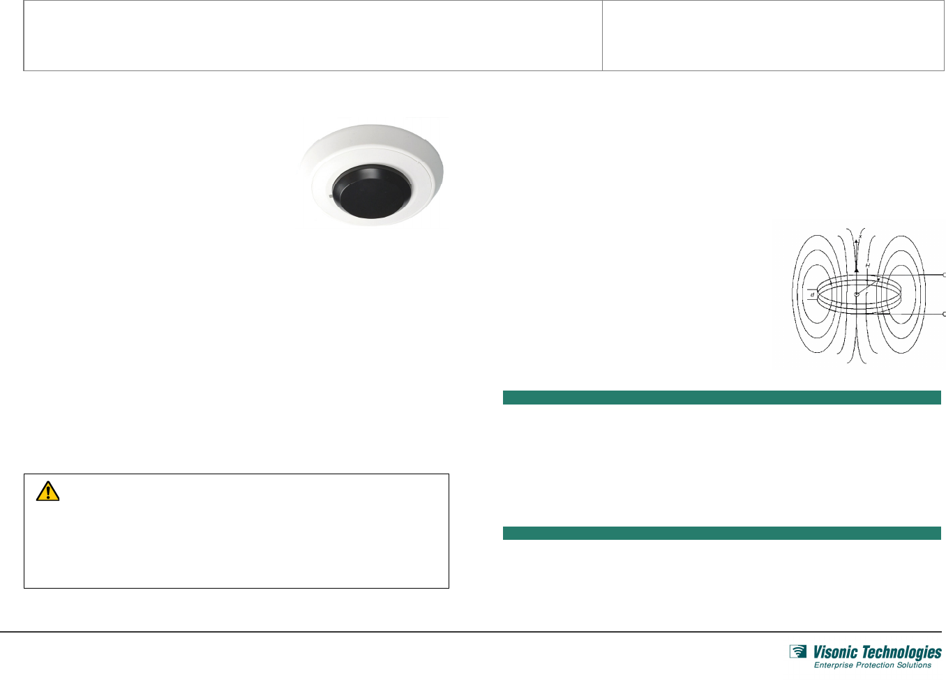
Elpas Low Frequency (LF) Exciters from Visonic
Technologies are supervised*, short-range, wireless
emitters that add pin point detection functionality to
EIRISTM based RFID installations.
Elpas Low Frequency (LF) Exciters can be installed
surface mounted on walls or on fixed or in dropped
(false) ceilings. Elpas LF Exciters are deployable in
either a basic stand-a-lone configuration designed to cover normal size single doorways or in
a master–slave configuration (1 master and 1 slave unit) for accurate, synchronized coverage
of large indoor, open complex-shaped areas.
Elpas LF Exciters emit harmless, adjustable low power, low frequency; sphere shaped
magnetic (125 KHz) fields up to 3m (10ft) in radius. The emitted fields are user tunable so
that they can precisely cover any indoor doorway or restricted entrance/exit area. As a result,
whenever an active Elpas RFID tag or badge (i.e. ETC, WTA, Baby Tag, Personnel Badge)
enters the magnet field; the corresponding LF Exciter automatically triggers the moving RFID
device to transmit special data messages (including the Exciter ID code). The messages are
immediately received and relayed by strategically located Elpas RF readers for monitoring,
alert notification and subsequent event logging.
* LF Exciters (from hardware Version C) transmit operational RF status messages plus output
power trouble alert messages configurable and supervised via EIRIS software.
CAUTION: It is important that you read, understand, and follow the
instructions in this document. If you have questions, call your local Visonic
Technologies support representative.
This document is intended for trained system integrators, field service or
maintenance engineers that need to troubleshoot problems in the EIRIS
system, or configurations and processes.
LF Transmissions
Transmission Rate: Continuous bursts of LF transmissions (each about 12ms in duration).
Supervision RF Transmissions
Transmission Rate: 1 RF transmission (about 2ms in duration), 10 seconds apart.
Transmitted Message Type: 433.9 MHz Elpas Tag (badge) protocol including ID LF Exciter
code (ID code = OOODXX where XX is ID number of the LF exciter
Installation Guidelines
LF Exciters generate an omni directional magnetic
radiation pattern that is almost spherical in area. As
a consequence ceiling mounted Exciters may result
in the LF penetration of adjacent floors and rooms.
Each stand alone or master LF Exciter has a
detection range up to a 10ft/ 3m radius. For wider
area coverage, enhanced detection capability or
direction determination a master/slave configuration
should be used.
Optimizing Performance
• General Placement: Position LF Exciters at least 30cm (12 inches) from any
metal barriers (such as signs/pillars/beams) in any direction.
• Single Doors: To thoroughly cover an exit without penetrating excess areas, the
LF Exciter should be mounted on a wall, at waist height, next to the door.
Additionally, the LF field should be adjusted to cover only the width of the door.
• Double Doors: A master/slave configuration may be used by mounting the master
exciter to the right of the double doors and the slave to the left of the doors.
Placement Warning
• LF Exciters may not be mounted on metallic surfaces.
• LF Exciters must be mounted as far away as possible from all other pieces of
equipment that may emit magnetic fields (such as large electrical motors, HVAC
and refrigeration compressors, etc.).
Main Circuit Board Components
Low Frequency Exciters - Installation Guide _________________________________________________________________________________________
Page 2 of 8
DTA03N01_V13
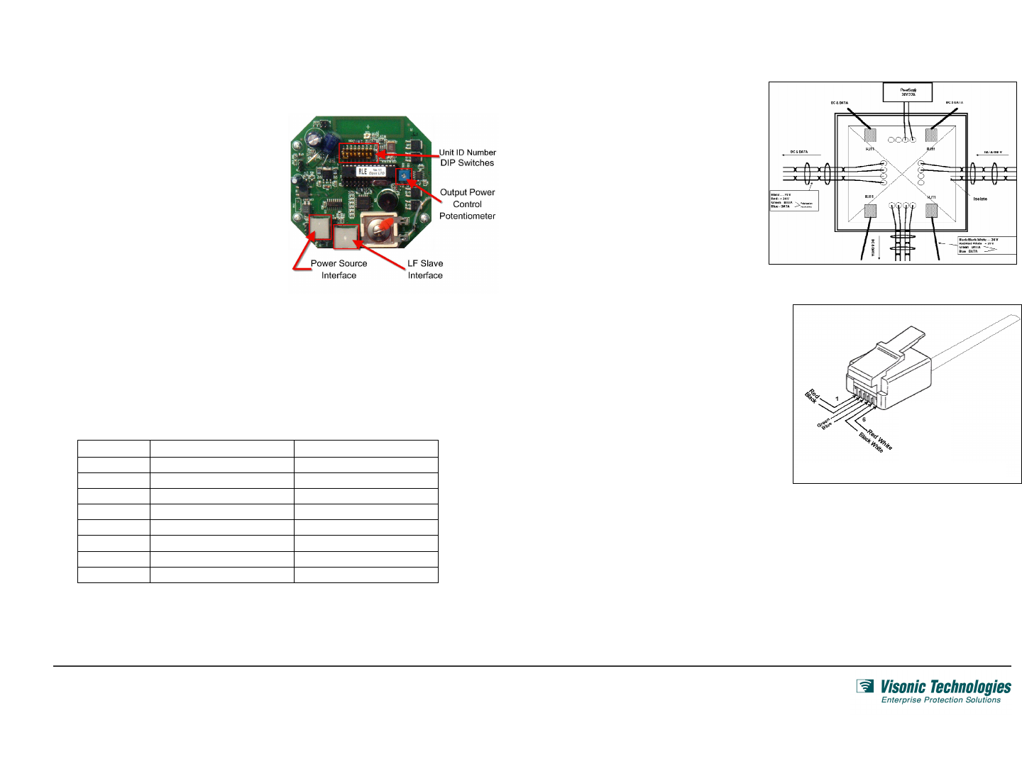
The key setup and configuration circuitry components used by the standalone or master
RF Exciter are detailed below
Unit ID Number
DIP Switches
Used for manually setting the
unit ID number of a master
or standalone LF Exciter.
Output Power
Control
Potentiometer
Used for manually tuning the
size of generated output
detection field
Power Source
Interface
Female RJ11 connector to
external 24 VDC nominal
power source via the EJB
junction box
LF Master/Slave
Interface
Female RJ45 connector to
LF Exciter slave unit
(master/slave configuration)
Setting the ID Number of the LF Exciter
Each Stand-alone or Master LF Exciter must be assigned a unique ID number
to make it possible for EIRIS to recognize the device. Locate the DIP switches
on the circuit board of the exciter and set the switch
settings as required. Use a scientific calculator or in EIRIS, the General tab of
the reader configuration for to determination the correct switch settings.
Refer to the table below for unit numbers to avoid using:
NO INVALID LF EXCITER ID (HEX) INVALID LF EXCITER ID (BIN)
1 13 00010011
2 35 00110101
3 4B 01001011
4 4D 01001101
5 5C 01011100
6 B8 10111000
7 D5 11010101
8 DC 11011100
CAUTION: Set the DIP switch before powering up the LF Exciter.
Never change the DIP switch settings once the LF Exciter is powered up.
Wiring the LF Exciter
Power from an external source
(24 VDC nominal ± 30%; 200mA)
is supplied to a standalone or
master LF Exciter via the EJB
junction box.
A bus topology network may be
branched for LF Exciters by
connecting only the power
connectors as shown here.
For connecting a standalone or
master LF Exciter to a EJB junction
box, use an unshielded 6 conductor
26 AWG solid cable crimped at both
ends with a RJ11 (6P6C) connector.
Ensure that the correct order of the
wires is maintained as shown here.
1 +V
2 - V
3 DATA
4 DATA
5 -V
6 +V
Low Frequency Exciters - Installation Guide _________________________________________________________________________________________
Page 3 of 8
DTA03N01_V13
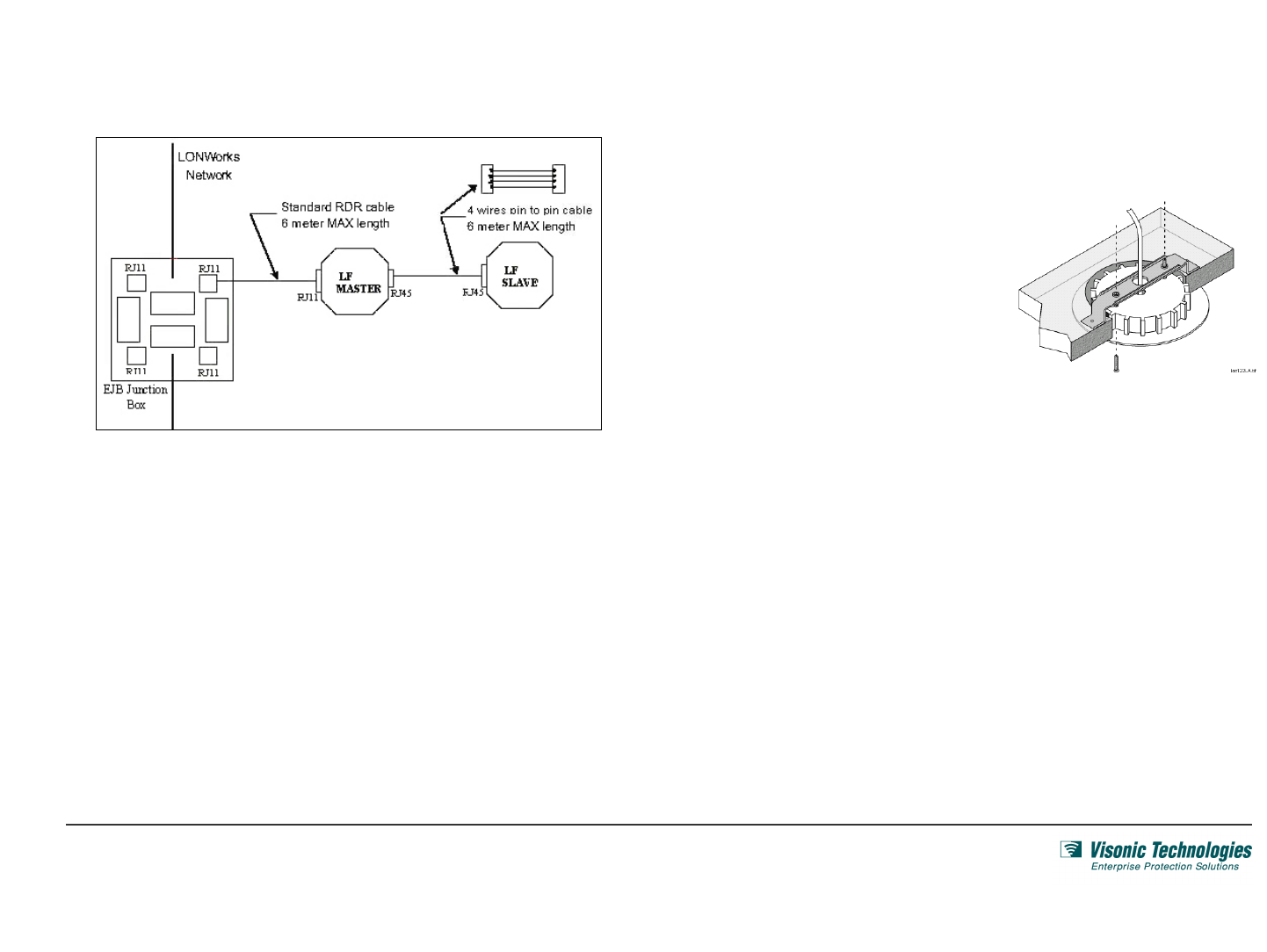
To wire a Master/Slave configuration, use an unshielded 4 conductor 26 AWG solid
cable crimped at both ends with a RJ45 (8P8C) connector as illustrated below:
When the Master LF Exciter (from hardware Version C, Revision A-1) senses that the Slave
has been disconnected, the B1 bit on the RF supervision transmission is set to Down.
Flush Mounting to Drop Ceilings or Interior Hollow Walls
1. Separate the LF Exciter from its base by pressing one of the snaps (identified by a
square hole) using a small screwdriver.
2. Then cut a 5 inch (12.7 cm) diameter mounting hole in the drop ceiling or the hollow
wall where the LF Exciter is to be flush mounted.
3. Pull the 6P6C power cable (for master
slave configurations the additional 8P8C
interface cable as well) trough the cable
entry hole of the RDR1 mounting bracket
and the LF exciter base.
4. Insert the RDR1 mounting bracket
through the mounting hole and position
it carefully so it is firmly supported.
5. Insert the base of the exciter into the mounting hole. Next, screw the base to the RDR1
mounting bracket place using the 2 supplied screws. Ensure that the screw heads are
recessed inside the screw holes. If not the LF Exciter will not close properly and damage
may occur.
6. Connect the power and interface cables to the LF Exciter; set the DIP switch and adjust
the units' output power. Then, insert the LF Exciter back into its base.
7. Finally walk test the LF Exciter using either an Elpas LF Meter or an active Elpas
Tag/Badge to verify that the placement and output power of the device is correct.
Surfacing Mounting to Solid Ceilings or Walls
1. Separate the LF Exciter from its base by pressing one of the snaps (identified by a
square hole) using a small screwdriver.
2. Using the base of the exciter as a template mark the locations of the two mounting
holes and the cable pass through.
3. Drill holes at the marked areas to accommodate the required mounting hardware and
the diameter of the power and interface cables.
Low Frequency Exciters - Installation Guide _________________________________________________________________________________________
Page 4 of 8
DTA03N01_V13
4. Insert base of the exciter into
the surface mounting ring.
Orient the mounting ring so it is
facing the ceiling or the wall.
5. Pull the 6P6C power cable (for
master slave configurations the
additional 8P8C interface cable
as well) trough the cable entry
hole of the LF exciter base.
6. Screw the base to the wall or ceiling using the 2 supplied screws. Ensure that the screw
heads are recessed inside the screw holes. If not the LF Exciter will not close properly and
damage may occur.
7. Connect the power and interface cables to the LF Exciter; set the DIP switch and adjust the
units' output power. Then, insert the LF Exciter back into its base.
8. Finally walk test the LF Exciter using either an Elpas LF Meter or an active Elpas Tag/Badge
to verify that the placement and output power of the device is correct.
Remote Supervision Management
Elpas LF exciters (from hardware Version C) transmit RF messages (as if the devices were
badges) for the purpose of supervision.
Supervision alerts include: Operational RF Status & Output Power Trouble
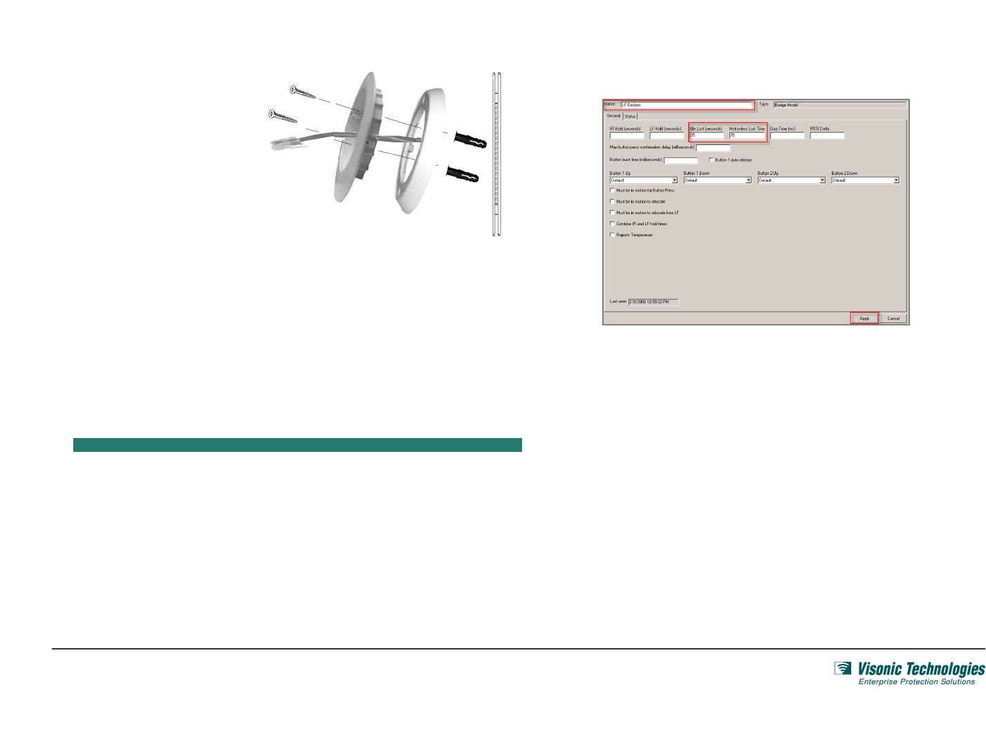
Configuring an Operational RF Status Alert
EIRIS can be configured to generate an Operational RF Status alert whenever a LF Exciter has
not been seen by EIRIS for a specified period of time.
1. Ensure that the LF Exciter to be supervised is correctly defined and configured.
2. Define a new Badge Model as detailed in the following steps:
Right-click on the All Badge Models branch of the Component tree.
Select Add Badge Model.
The General tab of the corresponding Badge Model Configuration (with default name)
form also appears in the EV2 setup pane.
Update the Badge Model Name so that it denotes that it is defined for a LF exciter.
Update the Idle Lost and the Motionless Lost interval values to 35 seconds,
respectively.
Press Apply; the badge model parameters are saved.
3. Define a new Badge that will represent the LF Exciter to be supervised as detailed in
the following steps:
Right-click on the All Badges branch of the Component tree. Select Add By Type;
the Add Object box appears.
Select the Badge icon by clicking on it. Then press Add; a new Badge sub-branch
(with default name) appears in the Components tree.

Low Frequency Exciters - Installation Guide _________________________________________________________________________________________
Page 5 of 8
DTA03N01_V13
The General tab of the corresponding Badge Configuration form appears in the
EV2 setup pane
Update the Badge Name so that it will denote a particular LF exciter.
Enter an ID Number of 000D##, where ## is the LF Exciter ID as set on the
DIP switch on the main circuit board of the device during installation.
Select the Badge Model that was created in the previous step) from the badge model
pull-down menu.
Press Apply; the badge parameters are saved. Then Repeat Step 2 (in is entirety) for
each additional LF Exciter that is to be associated with the new alert.
4. Define a new Operational RF Status alert (using the Lost Away alert) that is to supervise
the operational RF status of the LF exciters as detailed in the following steps:
Right-click on the All Alerts branch of the component tree. Select Add By Type; the
Add Object box appears.
Select the Lost Away icon by clicking on it. Then press Add; a new Lost Away alert
sub-branch (with default name) appears in the components tree.
The General tab of the corresponding Alert Configuration form also appears in the
EV2 setup pane.
Update the Name of the Device Away alert so that the new name will denote the
intended usage.
Enter a Message that is to be sent to the designated client machines when the alert
is trigged. Then press Apply; the general parameters are saved.
Access the Inputs tab. Next expand the Badges tree in the Badges Tree pane to
show all the of the defined badges including the LF Exciters.
Select the LF Exciter(s) that are to be supervised.
Enable the All Status Types option in the Status Tree pane.
(Optional) Increase/Decrease the Time Interval (seconds) after the device has
been declared 'Lost/Away' that is to transpire before alert is triggered in the 'Time
Required' value field.
(Optional) Increase/Decrease the Time Interval (seconds) that is to transpire
before the alert is cleared in the 'Automatically clear after' value field.
Press Apply; the input parameters are saved. Complete the Outputs and Schedule
tabs of the Alerts Configuration form as required.
Low Frequency Exciters - Installation Guide _________________________________________________________________________________________
Page 6 of 8
DTA03N01_V13
Specifications
ELECTRICAL
Power Requirements 24 VDC nominal ± 30%; 200mA. (500mA at start-up)
Power Consumption Approx 2W (power consumption is a function of address
(per DIP switch settings, where FF=max and 00=min)
Status Indications Power On: Red LED pulses 5 times upon power on; then remains constant.
Invalid ID Code: Red LED pulses continuously; Buzzer beeps repetitively
Frequency Output & Format LF: 125KHz; 3 byte messages (Preamble, Exciter ID and CRC)
RF (supervision): 433.9MHz; Elpas Tag Format (see tag documentation)
Output Bit Rate 2,000 bits per second
Output Power Adjustable, using on-board trim control potentiometer
Magnetic Field - Effective Range Up to up to 3m (10ft) radius
Device Interfaces RJ11 (6P6C) connector to power source via EJB box;
RJ45 (8P8C) to slave (master-slave configuration)
LF Power Transmission Output Less than 60 dbµv at 30 meters (100 feet)
Supervisory RF Transmission
Rate
433.92 MHz RF transmission 2ms duration , 10 second intervals
LF Transmission Rate Continuous bursts of LF transmissions (each about 12ms in duration)
Supervision Management Using EIRIS software
Exciter ID code Set by on-board 8 position DIP-switch
GENERAL
Construction Polymer plastic
Dimensions 17cm x 4 cm (6.6 inches x 1.6 inches)
Weight 200 grams (0.45 lbs) approximate
Temperature & Humidity -10°to 70°C (14°to 159°F); 20% to 80% non-condensing
Fire Resistance Using optional fire proof cover (5-RDT09101)
Warranty One year limited warranty
FCC Compliance FCC Part 15.209 and 15.231e
FCC ID O4X5-RLE00125
Ordering Details
PART INFORMATION
5-RLE00125 LF Exciter
5-RLE00125-1 LF Exciter, Master
5-RLE00125-2 LF Exciter, Slave
5-RLE00125-W LF Exciter, WHT
5-RLE00125-1W LF Exciter, Master WHT
5-RLE00125-2W LF Exciter, Slave WHT
OPERATIONAL ACCESSORIES
5-RDT09103 RDR surface mount ring (5 units)
5-RDT09100 RDR1 mounting bracket (5units)
5-RDT09101 RDR1 fire proof cover (5units)
Standards Compliance
This device complies with Part 15 of the FCC Rules; and its operation is subject to
the following two conditions:
• This device may not cause harmful interference
• This device must accept any interference received, including interference
that may cause undesired operation.
For a Class B digital device or peripheral, the instructions furnished the user shall
include the following or similar statement, placed in a prominent location in the
text of the manual:
NOTE: This equipment has been tested and found to comply with the limits for a
Class B digital device, pursuant to Part 15 of the FCC Rules. These limits are
designed to provide reasonable protection against harmful interference in a
residential installation. This equipment generates uses and can radiate radio
frequency energy and, if not installed and used in accordance with the instructions,
may cause harmful interference to radio communications. However, there is no
guarantee that interference will not occur in a particular installation.
If this equipment does cause harmful interference to radio or television reception,
which can be determined by turning the equipment off and on, the user is
encouraged to try to correct the interference by one or more of the following
measures:
• Reorient or relocate the receiving antenna.
• Increase the separation between the equipment and receiver.
Connect the equipment into an outlet on a circuit different from that to
which the receiver is connected.
• Consult the dealer or an experienced radio/TV technician for help.
Warning!
Changes or modifications to this equipment not expressly approved by the party
responsible for compliance (Visonic Technologies Ltd.) could void the user’s
authority to operate the equipment.

Low Frequency Exciters - Installation Notes ________________________________________________________________________________________
Page 7 of 8
WTA03N01_V11
W.E.E.E. Product Recycling Declaration
For information regarding the recycling of this product you must contact the company from which you orignially purchased it. If you are
discarding this product and not returning it for repair then you must ensure that it is returned as identified by your supplier. This product is not
to be thrown away with everyday waste.
Directive 2002/96/EC Waste Electrical and Electronic Equipment
Low Frequency Exciters - Installation Notes_V11 Modifications Reserved Printed June 2006
Product Warranty
Visonic Technologies Ltd., and its affiliates, (hereinafter collectively referred to as "the Manufacturer")
warrants its products (hereinafter referred to as "the Product”) to be free of defects in materials and
workmanship under normal operating conditions and use for a period of one year from the date of
shipment by the Manufacturer. The Manufacturer's obligations shall be limited within the warranty period,
at its option, to repair or to replace the defective Product or any defective component or part thereof. To
exercise this warranty, the product must be returned to the manufacturer freight prepaid and insured.
This warranty does not apply to repairs or replacement caused by improper installation, Product misuse,
failure to follow installation or operating instructions, alteration, abuse, accident, tampering, repair by
anyone other than the Manufacturer, external causes, and failure to perform required preventive
maintenance. This warranty also does not apply to any products, accessories, or attachments used in
conjunction with the Product, including batteries, which shall be covered solely by their own warranties, if
any. The Manufacturer shall not be liable for any damage or loss whatsoever, whether directly, indirectly,
incidentally, consequentially or otherwise, resulting from a malfunction of the Product due to products,
accessories, or attachments of others, including batteries, used in conjunction with the Product.
THE MANUFACTURER MAKES NO EXPRESS WARRANTIES EXCEPT THOSE STATED IN THIS STATEMENT.
THE MANUFACTURER DISCLAIMS ALL OTHER WARRANTIES, EXPRESS OR IMPLIED, INCLUDING
WITHOUT LIMITATION IMPLIED WARRANTIES OF MERCHANTABILITY AND FITNESS FOR A PARTICULAR
PURPOSE. THE MANUFACTURER’S SOLE RESPONSIBILITY FOR WARRANTY CLAIMS IS LIMITED TO
REPAIR OR TO REPLACE AS SET FORTH IN THIS STATEMENT.
The Manufacturer shall have no liability for any death, personal injury, property damage, or other loss
whether direct, indirect, incidental, consequential, or otherwise, based on a claim that the Product failed to
function. However, if the Manufacturer is held liable, whether directly or indirectly, for any loss or damage
arising under this limited warranty or otherwise, regardless of cause or origin, the Manufacturer's
maximum liability shall be limited to the purchase price of the Product, which shall be fixed as liquidated
damages and not as a penalty, and shall be the complete and exclusive liability of the Manufacturer.
The Manufacturer shall not, under any circumstances whatsoever, be liable for any inaccuracy, error of
judgment, default, or negligence of the Manufacturer, its employees, officers, agents, or any other party,
or of the purchaser or user, arising from any assistance or communication of any kind regarding the
configuration, design, installation, or creation of security system involving the Product, that being the
responsibility of the purchaser or user.
If the Manufacturer is unable to make such repair or replacement, the Manufacturer’s entire liability shall
be limited to the cost of a reasonable substitute product. The Manufacturer shall not be responsible for
any dismantling, installation, reinstallation, purchasing, shipping, insurance, or any similar charges.
The Manufacturer shall have no liability for any damages, including without limitation, any direct, indirect,
incidental, special, or consequential damages, expenses, costs, profits, lost savings or earnings, or other
damages arising out of the use of the Product or the removal, installation, reinstallation, repair or
replacement of the Product or any related events. In the event that there is any liability against the
Manufacturer, such liability shall be limited to the purchase price of the Product which amount shall be
fixed as liquidated damages.
The purchaser and user understand that this Product may be compromised or circumvented by intentional
acts; that the Product will not in all cases prevent death, personal injury, property damage, or other loss
resulting from burglary, robbery, fire or other causes; and that the Product will not in all cases provide
adequate warning or protection. The purchaser and user also understand that a properly installed and
maintained alarm may reduce the risk of events such as burglary, robbery, and fire without warning, but it
is not insurance or a guarantee that such events will not occur or that there will be no death, personal
injury, property damage, or other loss as a result of such events.
By purchasing the Product, the purchaser and user shall defend, indemnify and hold the Manufacturer, its
officers, directors, affiliates, subsidiaries, agents, servants, employees, and authorized representatives
harmless from and against any and all claims, suits, costs, damages, and judgments incurred, claimed, or
sustained whether for death, personal injury, property damage, or otherwise, because of or in any way
related to the configuration, design, installation, or creation of a security system involving the Product, and
the use, sale, distribution, and installation of the Product, including payment of any and all attorney’s fees,
costs, and expenses incurred as a result of any such events.
The purchaser or user should follow the Product installation and operation instructions and test the
Product and the entire system at least once each week. For various reasons, including but not limited to
changes in environmental conditions, electric, electronic, or electromagnetic disruptions, and tampering,
the Product may not perform as expected. The purchaser and user are advised to take all necessary
precautions for the protection and safety of persons and property.
This statement provides certain legal rights. Other rights may vary by state or country. Under certain
circumstances, some states or countries may not allow exclusion or limitation of incidental or
consequential damages or implied warranties, so the above exclusions may not apply under those
circumstances and in those states or countries. The Manufacturer reserves the right to modify this
statement at any time, in its sole discretion without notice to any purchaser or user. However, this
statement shall not be modified or varied except by the Manufacturer in writing, and the Manufacturer does not
authorize any single individual to act on its behalf to modify or vary this statement
.

Low Frequency Exciters - Installation Guide _________________________________________________________________________________________
Page 8 of 8
DTA03N01_V13
Manufactured In Israel
VT World Headquarters
Tel Aviv Israel
Tel: +972 3 7681400 *
marketing@visonictech.com
VT Americas
Bloomfield, CT (USA)
Tel: 860-242-0191
vta_marketing@visonictech.com
Visonic UK
Beckenham Kent, BR3 9BF, United Kingdom
Tel: +44-870-730-0840 *
vtuk_marketing@visonictech.com
Visonic D-A-CH
D-40215 D'sseldorf Germany
Tel: +49-(0)-221-600-696-0 *
support@visonictech.de