Elster Solutions EA2G-I Gas Meter Spread Spectrum Transmitter User Manual Final version
Elster Solutions, LLC Gas Meter Spread Spectrum Transmitter Final version
UserManual.wiki
>
Elster Solutions
>
EA2G-I User Manual
>
Final version - User Manual
Contents
1.
Final version - User Manual
2.
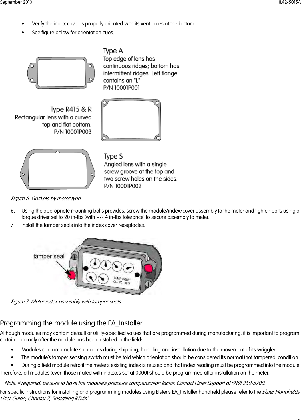
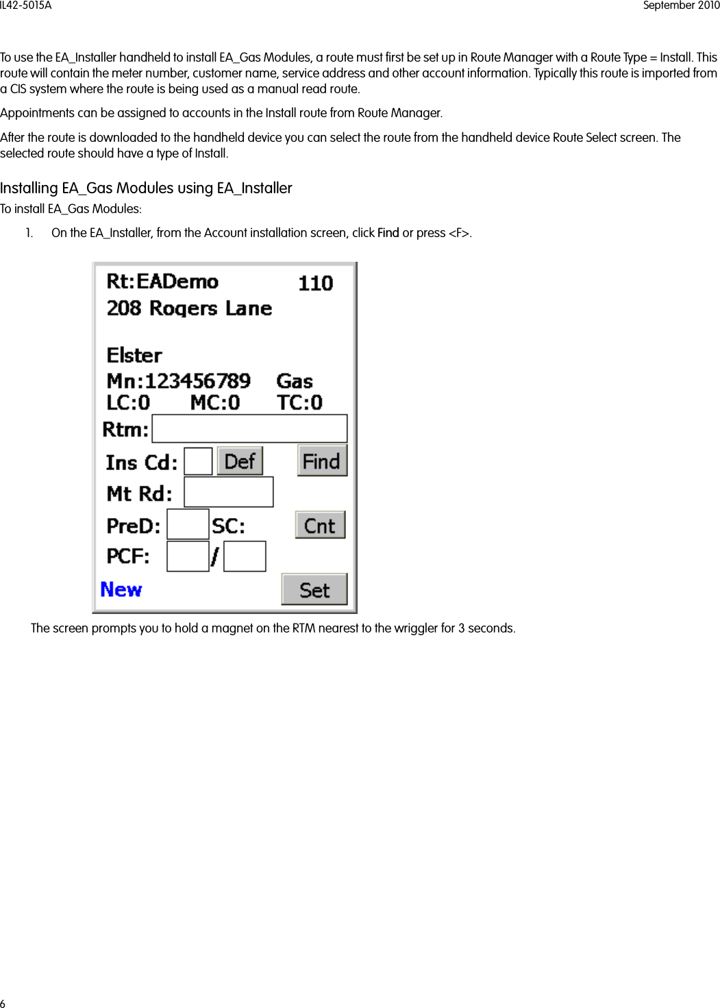
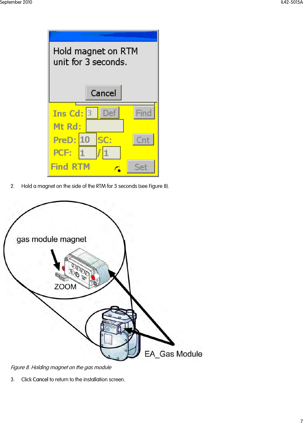
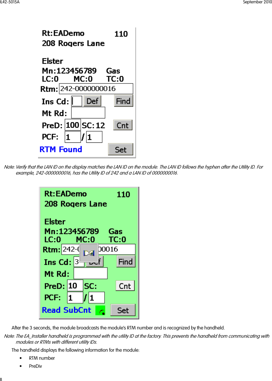
User Manual
Final version - User Manual
Navigation menu
Upload a User Manual
Namespaces
Wiki Guide
HTML
PDF
Info
Views
User Manual
Discussion / Help
Navigation