Elster Solutions ILC2I ILC2I User Manual USERS MANUAL
Elster Solutions, LLC ILC2I USERS MANUAL
UserManual.wiki
>
Elster Solutions
>
ILC2I User Manual
USERS MANUAL
Navigation menu
Upload a User Manual
Namespaces
Wiki Guide
HTML
PDF
Info
Views
User Manual
Discussion / Help
Navigation
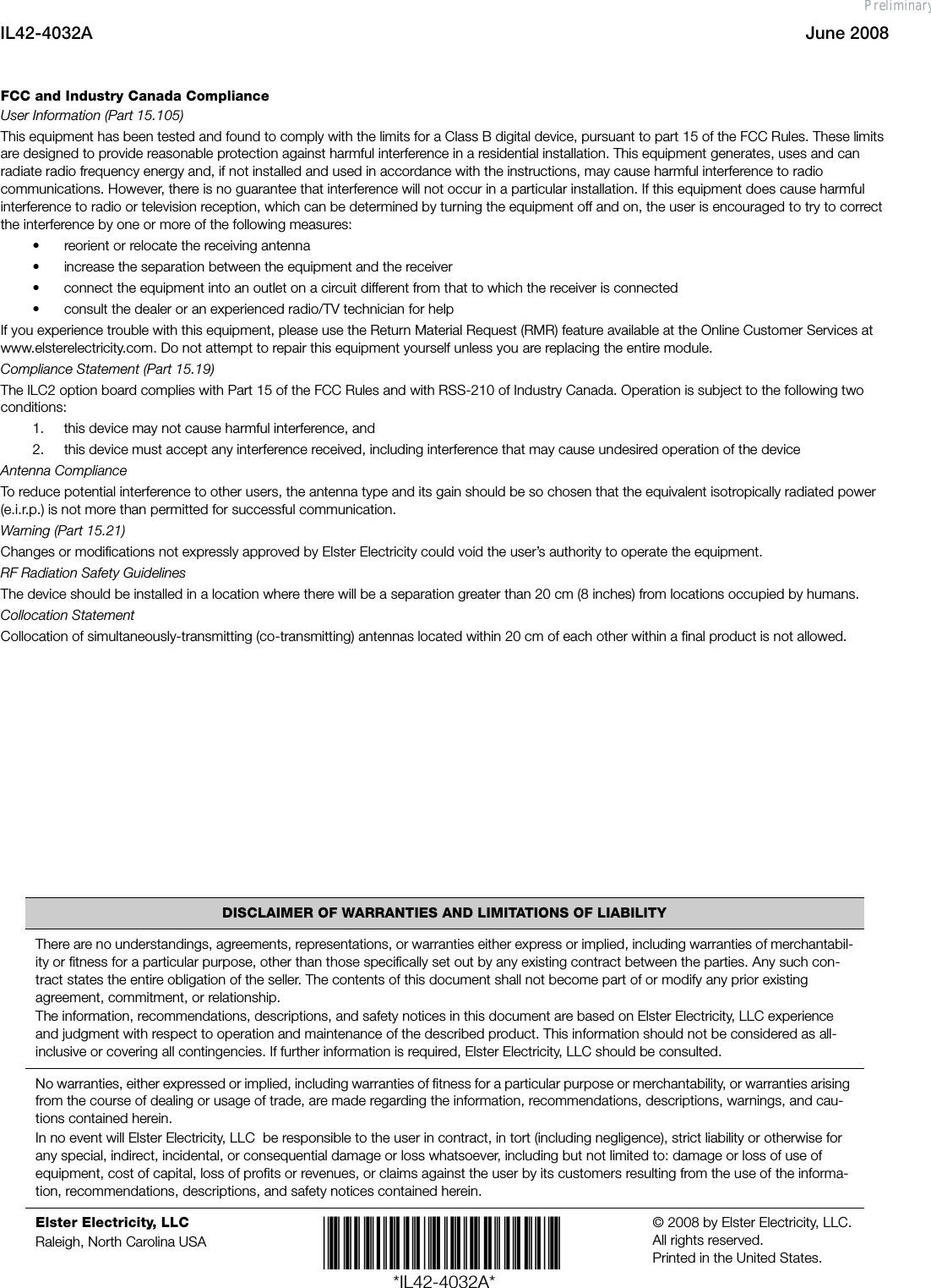
![IL42-4032A June 20082Figure 1. Retaining clip and connector leadLocal External AntennaIf the A3 ALPHA meter is used in a metal service cabinet, using a local external antenna may be necessary. To obtain better coverage, the local external antenna can be mounted on the top of the metal service cabinet or the meter socket enclosure (see [1] in Figure 2).Elster recommends Antenex Inc.’s 902-928 MHz Permanent Mount antenna (TRAB9023P).1 To mount the antenna on the service cabinet or meter socket enclosure, drill a 5/8-inch hole into the cabinet wall with a step drill. Insert the antenna through the hole. After the antenna is mounted, the antenna’s Type N female connector can be mated with the meter’s Type N male connector.For installations where the mounting for the local antenna does not provide a conductive metallic ground plane, the Antenex TRAB9023NP (no ground plane required) may be employed. The gain and pattern are virtually identical with the TRAB9023P version and the TRAB9023NP may also be employed on metallic ground planes with good results.Remote External AntennaIf the A3 ALPHA meter is used in a metal building, or the meter is installed in a location where the site requires an antenna at a greater height to overcome blocked signals, a remote antenna may be required. If a remote external antenna is used, a lightning/surge arrestor should be installed at the bottom of the socket enclosure (see [2] in Figure 2). Elster recommends a PolyPhaser DSXL IN-LINE EMP surge filter (Tessco P/N 491574).2NOTICEDo not use a standard RG-8/U cable with solid polyethylene dielectric. The losses in solid dielectric RG-8/U cables in short distances make solid dielectric RG-8/U cables unacceptable.The most economical connection to the remote external antenna is the RG-8/U “foam” or “LMR-400” type cable. This type of cable should be suitable for distances of up to 100 feet. The foam dielectric cable will incur a loss of approximately 3.9 dB in 100 feet (or approximately 2 dB in 50 feet). The coaxial cable should be mounted at the bottom of the meter socket in “drip loop” fashion. A “drip loop” is formed by bringing the coaxial cable to a point below the meter socket and then bending it back up to the connector. This forms a U-shape, which allows water to run down the cable exterior. Antenna cables should be ordered with N-type male connectors on each end.1Antenex, 2000-205 Bloomingdale Road, Glendale Heights IL 60131. Telephone: 630-351-9007. Website: antenex.com2PolyPhaser Corporation, 2225 Park Place, Minden, NV 89423. Telephone: 800-325-7170.Website: polyphaser.com.N-type connector to external antennaConnector leadExternal antenna connection leadWire tieRetaining clipPreliminary](https://usermanual.wiki/Elster-Solutions/ILC2I/User-Guide-961377-Page-2.png)
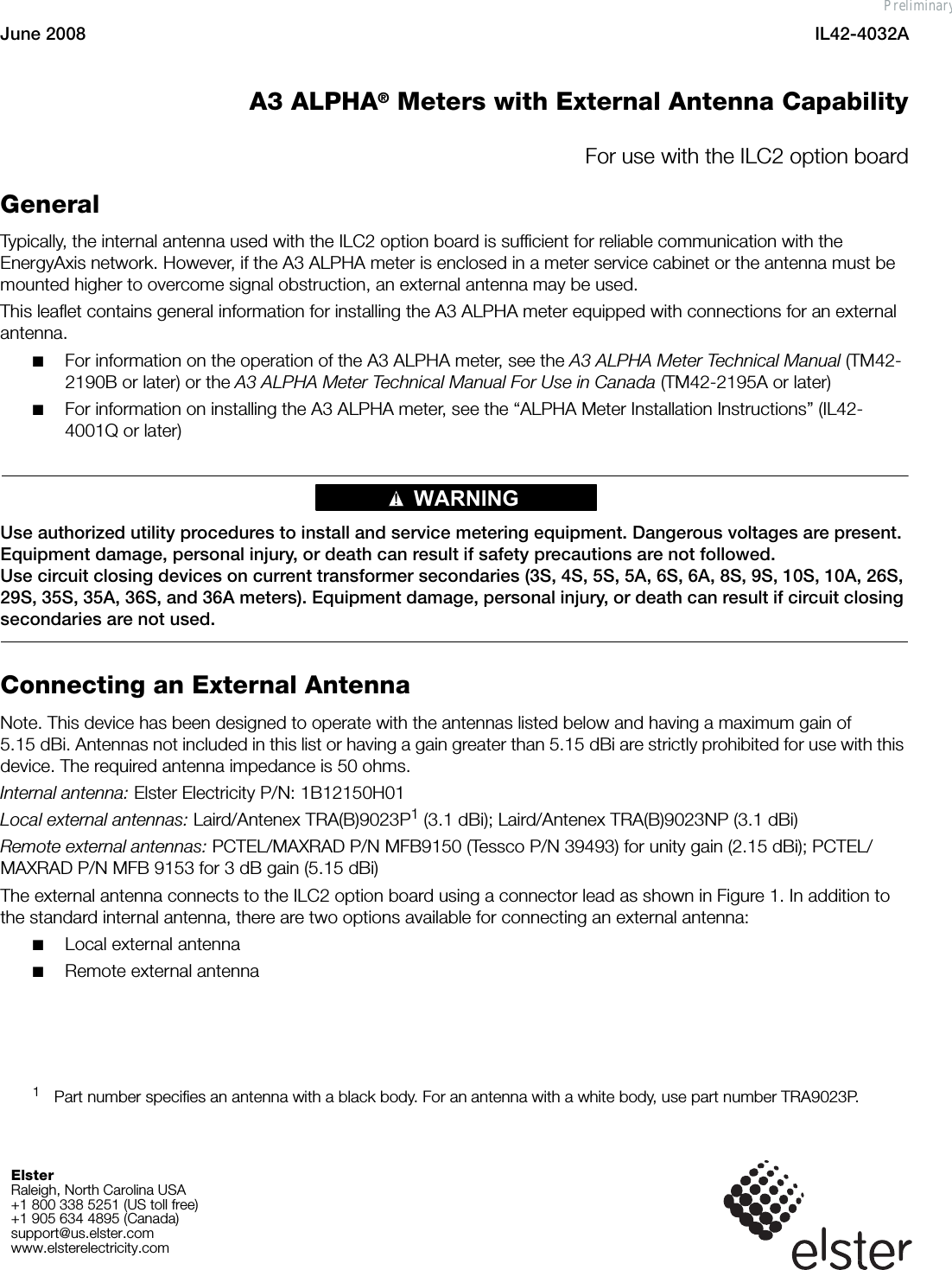
![June 2008 IL42-4032A3The collectors and nodes in the EnergyAxis System operate under Part 15.247 of the FCC Rules. Suitable antennas are omni-directional antennas of unity gain or 3 dB gain (2.15 and 5.15 dBi, respectively). Elster recommends the following, which are rated to withstand 100 mph winds and are fitted with Type N female connectors:■PCTEL/MAXRAD MFB9150 Series (Tessco P/N 39493) for unity gain (2.15 dBi)■PCTEL/MAXRAD MFB9153 Series (Tessco P/N 74330) for 3 dB gain (5.15 dBi)Regardless of the antenna selected, the antenna should be mounted with at least two MMK1 pipe clamps (Tessco SKU 68869). The antenna should be mounted in the clear, as free from the conductive or metallic obstructions as possible. The connectors should be sealed for waterproofing.Figure 2. External antenna optionsRemote antenna materials described in this IL can be obtained from the following:Tessco Technologies, Inc.11126 McCormick RoadHunt Valley, MD 21031-1494+1 800 508 5444tessco.comLaird/Antenex antennas can be obtained from the following:OEM Sales M6Laird Technologies1751 Wilkening CourtSchaumburg, IL 60173+1 847 839 6916 (telephone) or +1 847 839 6063 (fax)www.lairdtech.com[2] Lightning/surge arrestorN-type female connector for cable to remote external antenna[1] External antennaLocal external antenna installation Remote external antenna installationPreliminary](https://usermanual.wiki/Elster-Solutions/ILC2I/User-Guide-961377-Page-3.png)