Elster Solutions MMI01 Mini-Mobile Interrogator User Manual
Elster Solutions, LLC Mini-Mobile Interrogator
user manual

Table of Contents
1. Overview ____________________________________________________________ 0
1.1 System Components ______________________________________________________ 1
2. Setup _______________________________________________________________ 2
3. Controls & Indicators__________________________________________________ 3
3.1 Power Supply____________________________________________________________ 3
3.2 Power/Status Panel _______________________________________________________ 4
3.3 Transmitter/Receiver _____________________________________________________ 5
4. Operation ___________________________________________________________ 6
4.1 Reading Mode ___________________________________________________________ 6
4.1.1 GPS Operation &Alarms________________________________________________________ 9
4.2 Performance Enhancement Features _______________________________________ 10
4.2.1 GEO Mode _________________________________________________________________ 10
4.2.2 Dynamic Window ____________________________________________________________ 11
4.2.3 Frequency Scan______________________________________________________________ 11
4.3 Command Mode ________________________________________________________ 12
4.3.1 Summary Command __________________________________________________________ 12
4.3.2 Tools Command _____________________________________________________________ 17
4.3.3 Quit Command ______________________________________________________________ 27
4.3.4. Help Command _____________________________________________________________ 29
5. Troubleshooting _____________________________________________________ 32
Appendix A: File Formats _______________________________________________ 33
A.1 GUIDE File ____________________________________________________________ 33
A.2 READING.RTE File ____________________________________________________ 34
A.3 .VAN File______________________________________________________________ 36
Appendix B: Specifications ______________________________________________ 37

List of Figures
Figure 1. Mini-MI ______________________________________________________ 1
Figure 2. MMI Status Indicators __________________________________________ 3
Figure 3. Transmitter/Receiver Status Indicators _____________________________ 5
Figure 4. Reading Mode Display___________________________________________ 8
Figure 5. Summary Command Menus _____________________________________ 12
Figure 6. Summayr Display Data Format __________________________________ 13
Figure 7. Tools Command Menus_________________________________________ 17
Figure 8. Trouble Shoot Display __________________________________________ 18
Figure 9. System Setup Menu ____________________________________________ 20
Figure 10. Route Scan Menu_____________________________________________ 22
Figure 11. Backup Memory Menus________________________________________ 23
Figure 12. Frequency Control Menu ______________________________________ 24
Figure 13. Set Perm Menu_______________________________________________ 26
Figure 14. Quit Command Menus_________________________________________ 27
Figure 15. Help Command Menus ________________________________________ 29
Figure 16. Location & Time Menu ________________________________________ 30
Figure 17. Set Time & Date Menu ________________________________________ 31
Figure 18. READING.RTE Header Format_________________________________ 34
Figure 19. READING.RTE Record Format_________________________________ 34
Figure 20. READING.RTE Example File __________________________________ 35
Figure 21. VAN File Header Format______________________________________ 36
Figure 22. VAN File Record Format ______________________________________ 36
Figure 23. VAN File Example____________________________________________ 36

Chapter 1 Overview
Chapter 1: Trace MMI Overview
The Trace ® Mini-Mobile Interrogator (MMI) is a portable data retrieval and storage
system designed to provide remote meter reading in conjunction with the Trace meter
transponders. The Trace system is designed to convert the mechanical index reading of a
utility meter to a duplicate electronic register reading. This electronic register reading is
transmitted via radio frequency (RF) signals to the MMI. The Trace MMI reads each
transponder by use of an RF interrogation that consists of a unique serial number along
with a command requesting the contents of the electronic register. Each transponder is
selected for reading on either a first-in-first-out (FIFO) basis, a latitude/longitude (L/L)
basis, or a combination of the two GEO mode. The MMI obtains route data from a
customer supplied floppy disk containing the street address, latitude/longitude , and serial
number of each transponder that is to be read.
The MMI uses a GPS-based navigation system that tracks the vehicle position. If the
Lat/Lon mode of interrogation has been selected, whenever the MMI comes into the
range of a particular transponder it begins to send an interrogation for that unit. When
the transponder receives a signal with the correct serial number it transmits its electronic
register reading, tamper status, and an error detection code.
The MMI listens for each transponder reply using an 8-channel receiver. Reply data
integrity is confirmed by monitoring receiver data tracking signals and by an error
detection code known as a BCH code. A transponder reply is only accepted if the BCH
code analysis is valid. This ensures that the data was received without error. The meter
reading along with transponder status, receiver channel activity, time of the read, and
vehicle position at the time of the read is stored in an output file contained on a floppy
disk. Once the MMI has been initialized with the appropriate route data, the system will
collect readings automatically, allowing the operator to drive the route in a safe and
efficient manner.
Chapter 1 Overview
MMI System Components
Figure 1. Mini-MI
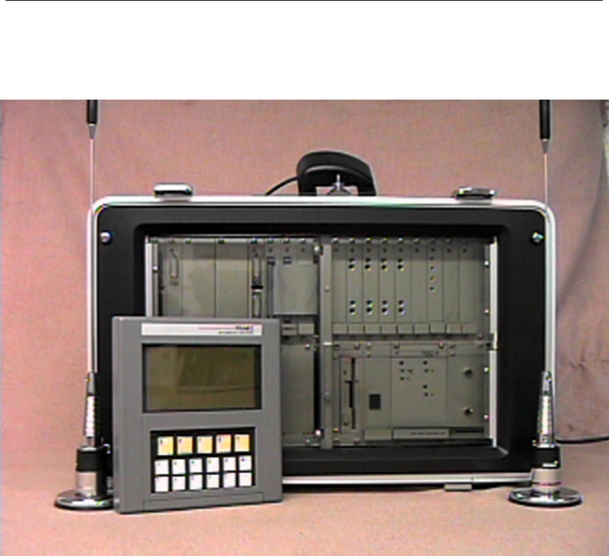
The MMI system consists of several main components, as displayed in figure 1. All
components are stored in the end covers during transportation. The entire system
consists of a handheld terminal, GPS receiver, transmitter antenna, receiver antenna,
power cord, and a main computer. The connection and usage of these components is
covered in chapter 2.

Chapter 2 Setup
Chapter 2: MMI Setup
The MMI is transported with all components contained in the carrying case. Before use,
these components must be unpacked and connected. Setup is simple and fast, and the
entire setup operation should take no more than five minutes. Use the following
instructions for a fast and trouble free setup:
• Unlatch the two latches on the rear cover door. Open the door slightly and then slide
the door off the two hinge pins. Now remove the GPS receiver, power cable, and
both antennas from their storage pouches. Store this door in a safe place.
• Next, unlatch the two latches on the front cover door. As above, remove the door,
then remove the handheld terminal and connecting cable, and the desired route disk
from their storage pouches. Store this door in a safe place.
• Now connect the transmit antenna to the appropriate connector and finger tighten
until snug. Next connect the receive antenna by pushing in on the connector and
twisting ¼ turn until it locks. Both antennas use unique connectors which are keyed,
so they cannot be connected backwards.
• Place both antennas on the top of the vehicle, and make sure that they are separated by
approximately 3 feet. A separation distance of two arms length apart is sufficient.
Typically the transmit antenna is placed at the front of the vehicle, and the receive
antenna at the rear. The coaxial cable may be routed over the top of the door on some
vehicles, or it may be necessary to route the cable through a slightly opened window.
Caution: If routing the cable over the top of the door, be certain to inspect the
distance between the top of the door and the vehicle frame to ensure there is adequate
clearance for the cable to avoid crushing it.
• Next connect the GPS receiver to the appropriate connector and finger tighten until
snug. Next moisten the suction cups on the GPS mount, and attach the unit to the
outside top of the vehicle windshield. As with the transmit and receive antennas, the
signal cable may routed over the top of the door, or through a window.
• The handheld terminal may now be connected using the supplied cable. Either end of
the cable may be connected to the terminal.
• Finally, connect the power cable to the appropriate MMI rear connector and finger
tighten until snug. Continue by inserting the opposite connector into the vehicle
cigarette lighter port.
Now the MMI is properly setup and ready to receive a route disk. Please take time to
read the following section to become familiar with the various controls and indicators
found on the MMI.
Chapter 3 Controls & Indicators
Controls & Indicators
The MMI uses a combination of LED’s (light emitting diodes), audible alarms, and the
handheld terminal to provide both status and a means of control to the operator. These
indicators are used to convey the status of the power supply unit, external voltages,
temperature, and transmitter/receiver operation. This section should be well understood
before operating the MMI. Failure to become familiar with the various status and control
features built into the MMI could lead to poor performance, or even system damage.
Power Supply Indicators:
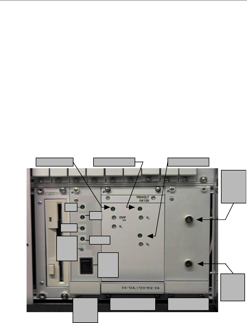
The power supply unit is equipped with 3 status LED’s. Each of these are illuminated
when the MMI is powered, and each respective supply voltage is operation normally. As
shown in figure 2, the LED’s denote whether the +5, +12, and -12 volt power supplies are
working properly. Also, the RF amplifier is equipped with an LED to indicate the
condition of the +12 volts used to power it. Under normal circumstances, all four of
these LED’s should be illuminated at all times while the MMI is powered.
Figure 2. MMI Status Indicators
+5 volts O
K
+12 volts O
K
-12 volts O
K
RF
AMP
Power
O
K
RF AmplifierPower SupplyPower /
Status
Pane
l
+12
Batt
Tem
p
AlarmAlarm
Silence
Switch Main
Power
Switch
RF
AMP
Enabled

Chapter 3 Controls & Indicators
Power/Status Panel Indicators & Control:
The power/status panel shown in Figure 2 contains 2 switches and 4 LED’s used to
monitor and control the main power provided to the MMI as well as to monitor the
internal temperature. All four of the status LED’s should be off under normal conditions.
The bottom switch is the main power switch and is used to power the MMI on and off.
The alarm silence switch is a push-button used to silence the audible alarm which is
activated any time a new alarm condition is detected. Once an alarm condition is
detected, an audible alarm will beginning sounding on and off at about 2 beeps per
second. Also, the alarm LED will begin flashing at the same rate as the audible alarm.
The audible alarm is used to alert the operator that a major status problem has been
detected, and requires immediate attention. If the alarm is chosen to be ignored, then the
alarm silence push-button may be pressed, which will shut off the audible alarm. The
alarm LED will continue to flash, however, until the actual alarm condition ceases. The
audible alarm will not sound again until all alarm conditions are eliminated and then one
or more conditions recur, or until the MMI is powered off then back on again. The
following three items are monitored by the power/status module for proper operation:
•+12 LED: This will be illuminated any time the external 12 volt supply
connected to the cigarette lighter drops to an unusable voltage.
This alarm may occur due to the power cable becoming
disconnected, or if the vehicle alternator is unable to produce
adequate operating current.
•Batt LED: This will be illuminated any time the internal battery voltage drops
to an unusable voltage. Once this alarm occurs, the MMI should
be immediately shut down. Ignoring this alarm could cause
unpredictable behavior. The MMI is able to operate approximately
10 minutes from the internal battery before the voltage becomes
unusable.
•Temp LED: This will be illuminated any time the internal MMI temperature
exceeds approximately 160° F. This condition may be caused
by several factors, including cooling fan failure, blocked fan
intakes, or excessive ambient temperature.
•Alarm LED: This will flash on and off approximately 2 times per second
whenever any or all of the +12, Batt, and Temp LED’s are
illuminated. This LED will continue to flash until all of the
+12, Batt, and Temp alarms are discontinued.
Chapter 3 Controls & Indicators
Transmitter/Receiver Status Indicators:
The MMI is equipped with eight receivers and one transmitter. All of these devices use
phase-locked-loops (PLL’s) to control each frequency with a high degree of accuracy.
The PLL’s also allow both transmitter and receiver frequencies to be easily changed with
software in real time. Many of the status LED’s to be described below display PLL
programming status. Since each PLL is software programmable, it is important to be able
to instantly verify if a particular one has been programmed correctly. It is possible to
improperly, either intentionally or accidentally, program a PLL to a frequency where the
transmitter or receiver is not able to operate correctly. In this case, the PLL OK LED
would be turned off.
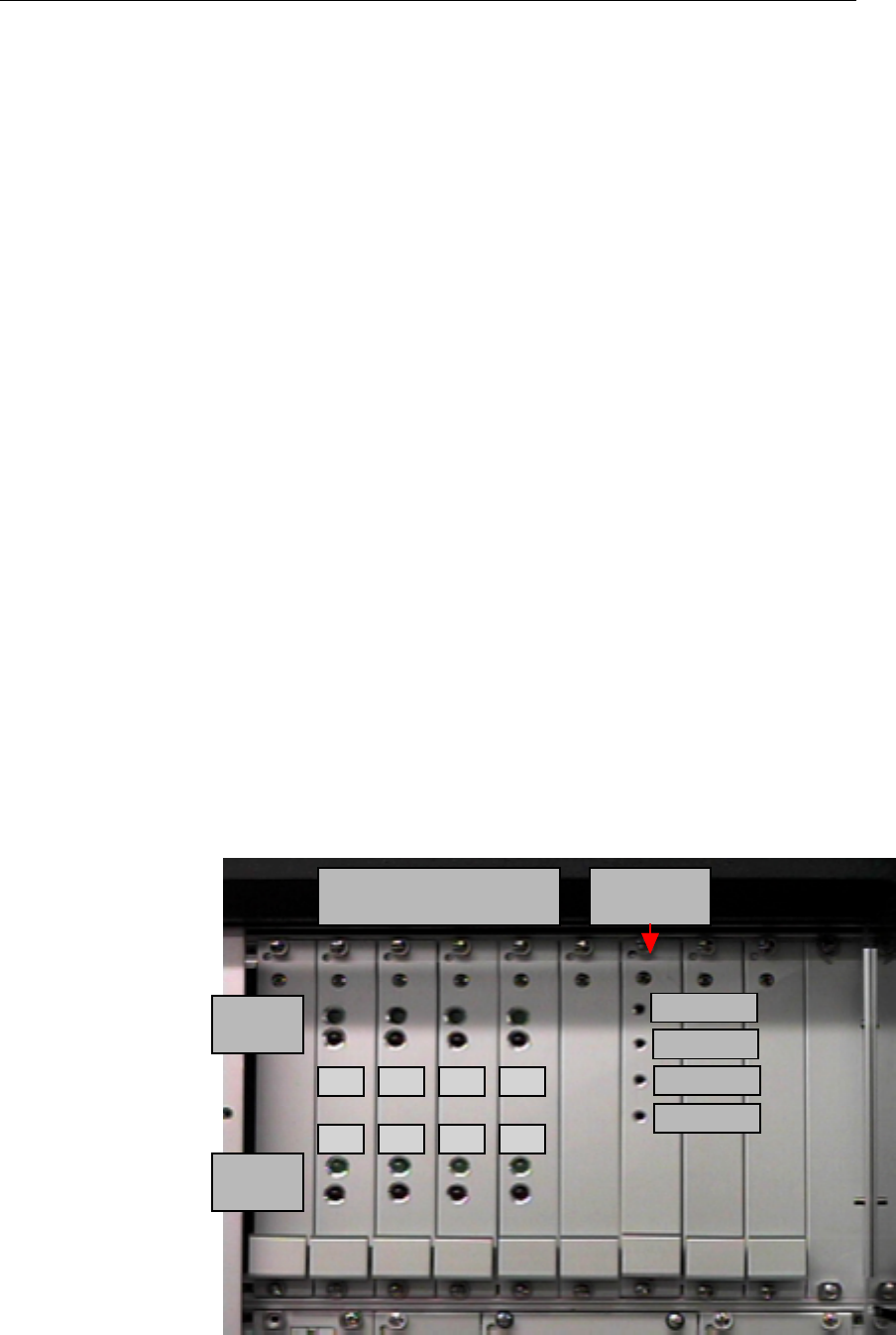
There are four receiver boards with two receivers on each board. These cards and their
locations are displayed in figure 3. Each receiver channel has two LED’s to display
programming and data status. Each green LED on the receiver boards is used to verify
that particular channel has been programmed to a valid frequency. The green LED’s
should be illuminated at all times during operation except for approximately 7 seconds
after MMI power is initially applied. During this time, the LED’s may be either on or off
randomly. During normal operation, all green LED’s should be illuminated. The red
LED’s will flash any time a particular channel is receiving valid data, visually verifying
that the receiver is working properly.
There is one transmitter board in the MMI and its location is shown in figure 3. The
transmitter has three LED’s used to display its status. The Power OK LED should be
illuminated any time the MMI is powered. As with the receiver PLL OK LED, the
transmitter PLL OK LED should be illuminated at all times. The TX On LED displays
whether the transmitter has been enabled by the software. Referring to figure 2, anytime
the TX On LED is illuminated, the RF Amp Enabled LED should be illuminated as well.
This verifies that the RF amplifier is operating.
Figure 3.
Transmitter/
Receiver Status
Indicators
Receiver Cards
#1&2 #3&4 #5&6 #7&8 Transmitter
Card
PLL OK
Data
PLL OK
Data
Power OK
PLL OK
N
ot used
TX On
CH1 CH3 CH5 CH7
CH2 CH4 CH6 CH8

Chapter 4 Operation
Chapter 4 Operation
Once the MMI is unpacked and the external components are properly connected, the route
disk may be inserted. Once the MMI is powered on, it performs several internal self-
checks. The indication and results of these tests are displayed on the hand-held terminal.
Some self-check problems will require the operator to press a key to acknowledge the
error before continuing. Please consult the trouble-shooting section of this manual if
errors occur during testing which prevent normal usage of the MMI. Once the self-check
has been completed, the MMI will read in a new route from the floppy disk (if the MMI is
not resuming a interrupted route). From here, the reading mode is automatically entered,
and meter reading may begin. Initially, MMI operating parameters are determined by the
settings contained in the Guide file. Many of these parameters may be overridden using
the system setup menu contained within the tools menu, discussed in the command mode
operating section.
All MMI operations fall into one of two basic modes, the Reading mode, and the
Command mode. The Reading mode is entered as soon as the MMI has been initialized.
The Command mode is used to analyze system data and parameters, alter operational
parameters, and perform miscellaneous tasks. The Command mode exists as a group of
five main commands. Each main command has various sub-menus that are supported.
The Reading mode does not require any operator input, and therefore has no menu
structure. There are two operations available in the Reading mode, the mode of reading
may be changed with the back space key, or the Reading mode may be exited by pressing
any other key. Pressing any of the yellow keys on the handheld terminal will invoke the
particular menu associated with that key.
Reading Mode
During normal operation of the MMI, the Latitude/Longitude (Lat/Lon or L/L) or GEO
mode of interrogation is used, and only transponders in the interrogation window are
interrogated. The interrogation window is an imaginary area surrounding the MMI that is
used to determine which transponders should be interrogated. This is simply a means in
which only certain transponders are selected for interrogation. Correspondingly, the
route may be driven in any order, since the MMI is constantly computing which
transponders are available for interrogation. A transponder will typically respond within
distances less than 2000 feet. The window size typically never needs to be changed, but it
may be necessary to reduce it, for example, when there are many transponders in a small
area. The smaller window size will allow for a smaller group of transponders to be
placed in the interrogation window, allowing them to be polled more quickly. The
window size may also be increased if there is some inaccuracies in the stored position of
a transponder, and you want to be sure that it is interrogated. If the window size is too
small, the MMI may never interrogate a particular transponder, which if interrogated,
would probably respond. Likewise, if the window size is set too large, then too many
transponders may be located in the window, which will slow down the interrogation for
each one.

Chapter 4 Operation
If the transponder Lat/Lon database is known to be good, then the performance
enhancement feature known as Dynamic Windowing may be enabled. This feature
examines the route transponder density in real time, and adjusts the interrogation window
automatically to allow only the optimum number of transponders into the window at a
given time.
The MMI should typically be used in the GEO mode of interrogation, although there may
be some instances where the FIFO mode may be necessary. In the FIFO mode, the MMI
scans the entire list of transponders in memory, and will attempt to read each unread
transponder one-by-one. If there is a large number of unread transponders in the database,
then this method can become very slow, even becoming ineffective. The FIFO mode
should only be used with a small number of transponders, and with the MMI either
stationary, or moving slowly. The FIFO mode may be used in the unlikely event that
there are problems with the navigation system. In FIFO mode, the vehicle location is not
used, therefore the data from the GPS system is not needed.
While in the Reading mode, various display items are used to provide feedback to the
operator. Using the parameters in the Guide file, or through the System Setup sub-menu,
the option may be selected to display information for each transponder with a good status
as it is processed by the MMI. Along with this option, the MMI can be directed to beep
with each good read. If desired, all display options may be turned off, or any combination
of options may be turned on.
The MMI may be placed in the Command mode at any time during operation. While in
the Command mode, the polling of transponders in the route is suspended. During the
execution of a particular route, the operator may change any of the System Setup
parameters as needed. The altering of the various parameters will not affect any of the
data in the route, but improper settings may adversely affect the performance of the MMI.
In the event that the System Setup parameters have been altered, and the original settings
are unknown, the operator may use the Break option, to halt the MMI. The MMI may
then be re-powered, and the default Guide file settings will be restored, and the prior
progress of the route will resume from the point where the Break option was used.
If the MMI is inadvertently turned off before a proper exit is accomplished, the current
route data will still be saved in backup memory. When the MMI is turned on again, the
route will continue from the point where it was at before it was turned off. The MMI may
be anywhere along the route when power is restored.
The vehicle position is constantly calculated and updated by the GPS navigation system.
The current vehicle position is used with the Lat/Lon or GEO mode of interrogation to
determine which transponders are within range of the vehicle, and may therefore be
interrogated. The current vehicle position is also used with either interrogation mode to
mark the Lat/Lon coordinates at the moment a good read takes place. The resulting
position data is stored with the other data for the transponder that responded. The mode
of interrogation may be changed at any time during the reading mode by pressing the

Chapter 4 Operation
backspace key. This will change the current interrogation mode from FIFO to GEO to
L/L. The mode of interrogation may also be changed using the System Setup command
within the Tools sub-menu.
As shown in figure 4, several pieces of information are displayed for a good transponder
reply during the reading mode (if the option to do so has been enabled). The first item
displayed is the serial number. Next, the meter reading is displayed. The next item is the
tamper status. A '.' is displayed for a non-tampered transponder. A 'T' is displayed for a
tampered transponder, ‘R’ for a tamper reset, and a 'F' is displayed if the tamper reset
command failed. The last field displayed is the street address of the meter.
Figure 4. Typical Reading Mode Display
A status line, shown above, is displayed at the top of the screen during the reading mode.
The time, mode of reading, number of good reads, GPS status, and number of
transponders inside the interrogation window are displayed. The GPS status area may be
at one of three statuses; ‘A’ indicates the GPS receiver is communicating with the MMI
and is producing valid position data, ‘S’ indicates that the GPS receiver is
communicating, but is not producing valid position data, and the self-navigation option is
active and functioning. The status ‘N’ indicates the GPS receiver is communicating, but
is not currently producing valid position data, and finally ‘-‘ indicates that the GPS
receiver is not communicating with the MMI properly.
2539216 1235 T 123 South Main St.
2558131 10144 . 96 Valley View Drive
0078067 9411 T 5995 Hagley Drive
0078067 . . . . . . . . R 5995 Hagley Drive
2121411 104551 T 4545 W. Brown Deer Rd.
2121411 . . . . . . . . F 4545 W. Brown Deer Rd.
10:22 | MODE : FIFO | Good : 200 | GPS : A | IW : ALL

Chapter 4 Operation
GPS Self Navigation & Lost Coverage Alarms
While in the Reading mode using either L/L or GEO modes, the MMI depends on the
continual position updates provided by the GPS receiver. Since the GPS receiver is
listening to satellites at various positions in the sky, objects such as tall buildings, trees
and high-growing foliage may block the view of some of the necessary satellites. When
such a blockage occurs, the GPS receiver is temporarily unable to provide Lat/Lon
coordinates. This naturally presents a serious problem while in L/L or GEO modes.
An option known as self-navigation is available that can continue producing Lat/Lon
position updates during brief GPS blockages. While in self-navigation mode, each time
the MMI receives a reply from a transponder, it takes the stored Lat/Lon coordinate for
that transponder and updates the vehicle position. While in self-navigation mode, the
Dynamic Window (see the performance enhancement section for a description) feature is
disabled, since the vehicle position may have a greater amount of error than normal. As
long as the MMI is continually receiving transponder replies, and the time between
successive reads is brief, then the self-navigation mode will continue. If however, a
period of no read activity occurs, then the self-navigation mode will be terminated, and
the FIFO mode will become active. Once self-navigation mode is terminated, it will not
resume again until the GPS status transitions from active to inactive. At the time valid
GPS position data becomes available again, the previous reading mode will become
active, and features such as Dynamic Window will be resumed, if enabled.
The MMI will alert the operator whenever the GPS becomes unable to produce position
data for any reason while in either L/L or GEO modes. Any time the GPS data becomes
unavailable, both an audible and message alert will be presented on the handheld
terminal. When the GPS position becomes unavailable, and self-navigation mode has not
been enabled, then a message will be displayed indicating that the GPS is blocked, and
FIFO mode is being initiated. If self-navigation mode was enabled at the time of GPS
blockage, then another message will be displayed indicating that GPS data is unavailable,
and the self-navigation mode is now active. If self-navigation mode is unable to continue
to produce position data, and GPS data is still unavailable, then an alert will be given
indicating that no position data is available, and FIFO mode is being initiated. Finally,
when GPS position data is restored, then another alert will be issued indicating this status.
Upon the resumption of GPS data, the reading mode which was active prior to the loss of
position data, as well as any performance enhancement features will be restored.

Chapter 4 Operation
Reading Mode Performance Enhancement Features
This section describes three MMI performance enhancement features that are often
employed to achieve a greater read success in certain situations. These features are the
GEO mode of interrogation, Dynamic Interrogation Window, and Frequency Scan. The
interrogation mode and the Dynamic Interrogation option may be enabled or disabled at
any time through the System Setup menu contained within the Tools command. The
interrogation mode may also be changed by pressing the backspace key while in Reading
mode. The Frequency Scan option is controlled from the Frequency Control menu within
the Tools command.
GEO Mode
As described in the Reading mode section, the GEO mode is similar to L/L mode in that
it uses the Lat/Lon locations of transponders to determine whether or not they should be
interrogated. However, it differs by also including in the interrogation window any
transponder that does not have a Lat/Lon coordinate. This most often occurs as new
transponders are added to an existing route. Most utilities do not have a means of
assigning a Lat/Lon coordinate at the time the transponder data is added to the route. As
a result, any new and uninitialized transponder would never be read while in L/L mode,
which is the primary mode of interrogation. Ordinarily, such transponders would have to
be read using FIFO mode, which would require the operator to be aware of where each
uninitialized transponder was located, and then switch interrogation modes until the
desired uninitialized transponder reading was obtained. On all but the smallest routes,
this need to constantly change interrogation modes would prove too unproductive to be
practical.
It is when a small number of uninitialized transponders are mixed into the route, that
GEO mode is used. GEO gets its name since transponders without coordinates are
geocoded as they are read. Geocoding is simply an action that assigns a Lat/Lon
coordinate to an object. Since the MMI records Lat/Lon information for each transponder
as it is read, once a read occurs there now exists an approximate Lat/Lon coordinate for
that transponder that may be used the next time that transponder is uploaded to the MMI.
Because the recorded Lat/Lon coordinate is the position where the MMI obtained the
reading, and not where the transponder is actually located, an additional restriction is
placed on the transponder before its reading is accepted. Each time a transponder reply is
received, a measure of its signal strength is recorded. The signal strength is proportional
to the distance to the transponder. As the MMI moves closer to the transponder, the
received signal strength increases. Therefore, the goal is to ensure that an uninitialized
transponder is read in GEO mode at a shorter range than normal. This ensures that the
recorded Lat/Lon coordinate will be effective the next time the transponder is read using
its new coordinates. To force this range restriction, a minimum signal strength
requirement is set in the System Setup menu that will be applied only to uninitialized
transponders being read in GEO mode. Other transponders with Lat/Lon coordinates, as
well as any transponder in FIFO mode will not face this restriction. Any transponder
reply

Chapter 4 Operation
that does not meet the signal strength requirement will result in a NO_RD status. This is
the same status which occurs any time the MMI does not receive a reply from a
transponder. The default minimum signal strength setting will most not likely never need
to be altered.
Dynamic Interrogation Window
Another performance enhancement feature implemented in the MMI is the Dynamic
Interrogation Window. Ordinarily, the interrogation window is set to a particular fixed
radius, and is not altered. This is normally acceptable for routes that have a consistent
installation density. However, on routes where there are widely varying installation
densities, a fixed interrogation window size can actually cause performance degradation.
If an excessive non-adjustable window size is used on a dense route, then the MMI will
not have as much time to re-interrogate transponders that are close, but have not yet been
read. This would result in either missed transponder readings, or would require the
operator to slow the vehicle to an unacceptable speed. Likewise, if the non-adjustable
window size becomes too small, then some transponders may never be interrogated at all
due to the vehicle speed and errors in the Lat/Lon coordinate information. To overcome
these limitations, the dynamic interrogation feature may be enabled by the System Setup
menu within the Tools command. When enabled, this feature will automatically adjust
the interrogation window size once per second to try to maintain a fixed number of
transponders in the window. This ensures that in situations where there are a large
number of transponders in a small area, the interrogation window size will be kept
smaller, so time is not wasted on interrogating transponders that are farther away. Also, it
ensures that in situations where there is a small number of transponders in a large area,
the interrogation window size will be allowed to grow, which prevents transponders from
never being interrogated at all.
Frequency Scan
To accommodate older transponders whose reply frequency has drifted down beyond
normal limits, the frequency scan feature may be enabled. This feature is enabled in the
Frequency Control menu contained in the Tools command. This feature will tune
receiver channel 1 between two frequency limits defined in the Frequency Control menu.
This allows transponder replies at abnormally low frequencies to be received, without any
special or additional effort. However, one caution should be noted when using this
feature. Since a receiver channel 1 is changing frequencies quite often, a transponder
reply may not be received since the receiver was at one frequency, while the transponder
was at another. This results in a potentially increased read time for transponders that
have abnormally low reply frequencies. The amount of speed degradation is related to
how wide the frequency scan is. The wider the frequency scan range, the potentially
slower the response time will be for low frequency transponders. By default the upper
frequency limit for the scan is one channel below the lowest channel currently
programmed in channels 2-8. Both limits may be arbitrarily changed within the
Frequency Control menu.

Chapter 4 Operation
Command Mode
The operator may stop reading at any time by pressing any key other than the backspace
key on the hand-held terminal. Doing so will place the MMI in the Command mode,
where various operations are available. Stopping the reading process in this manner will
not affect any previously read transponders, and the Reading mode may be entered or
exited as often as necessary. All transponder data is stored in non-volatile memory which
protects valuable data from being lost in the event of main power loss. This also allows
the operator to quickly and easily pause the MMI while in the process of reading a route,
and resume reading the remainder of the route at a later time. While in command mode,
transponder interrogation is suspended.
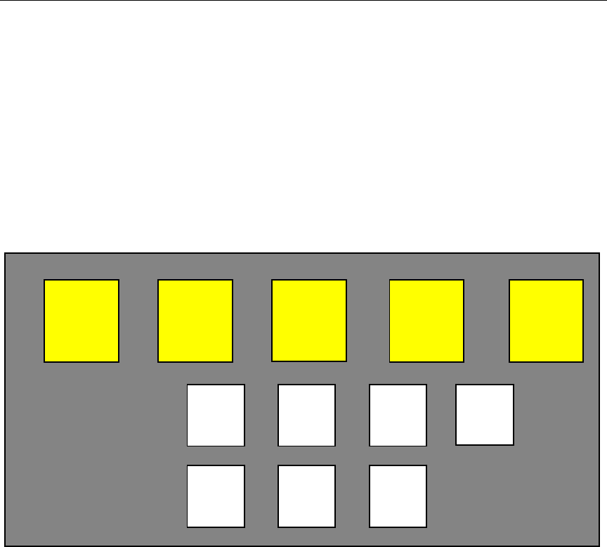
The Command mode consists of the following main commands: Summary, Reading,
Tools, Quit, and Help. Each of these main commands have various sub-menus from
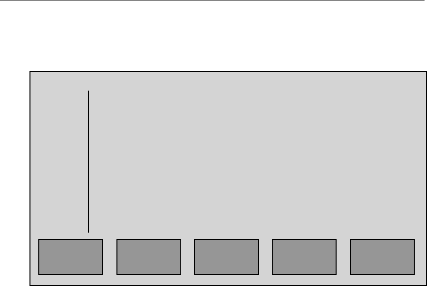
which to choose. On all Command mode menus the location of the menu squares on the
display roughly match their respective location on the keypad. Using the Summary menu
display in figure 5 as an example, the ALL menu selection would be chosen by pressing
the ‘0’ key on the handheld terminal. Each command is discussed in more detail in the
remainder of this section.
Summary Command
The Summary command menu is the invoked by pressing the ‘S’ key while in Reading
mode, or while the main Command mode menu is displayed. The six Summary command
menu selections display the total number of transponders having a particular status. As
an example, this information can be used to identify how many transponders have been
tampered with, then display each address so that a visual inspection of the transponder
may be performed.
Figure 5. Summary Command Sub-menus
SUMMARY READING TOOLS QUIT HELP
ALL
100
GOOD
90
UNRD
1UNINT
4
TMPD
5InWIN
3
Chapter 4 Operation
The Summary command menus display information in the format shown in Figure 6.
When the operator selects a particular Summary command menu, the MMI searches the
route for only those transponders that have responded accordingly.
Figure 6. Summary Display Data Format
The six menus of the Summary command detail the various possible states for the
transponders in the route. This serves to give a quick, detailed look at the progress being
made in the reading of the route. The definition of each Summary command menu and
associated transponder states are discussed below:
All All transponders in the route will be displayed.
Unrd Any unread transponders in the route will be displayed.
Unint Any transponders that have never been polled will be displayed.
Reminder: The MMI will not poll a transponder until it is in the
interrogation window while in the Lat/Lon or GEO mode of reading,
or unless it has not Lat/Lon coordinate, and GEO mode is active.
Good Those transponders that have been successfully read, including tampered units,
will be displayed. Refer to Table 1 for a summary of transponder status
definitions.
Tmpr Any transponders which have returned a tamper status will be displayed.
Inwin In the Lat/Lon mode of reading, all transponders which are in range of the MMI
read window and are displayed. In the FIFO mode of reading, all unread
transponders will be displayed as being in the window.
Summary Entry # Address SN # Status Reading
1 2804 Weber St. 2789321 G_NT 3749
2 12806 Weber St. 2930587 G_NT 9712
3 1474 Main St. 2002189 G_NT 7834
4 1795 North Main St. 2501987 G_NT 0328
4UP DOWN QUIT HELP

Chapter 4 Operation
Particular entries may be searched for in any of the summary displays by using the S
(search) key. This will allow the operator to input a street number, street name, serial
number, or just a part of an entry that corresponds to a transponder of interest. The
summary display will then display only those transponders that match the search string
and are in the main summary category initially selected.
The operator may also jump to a particular entry in the summary display, by typing in the
desired entry number and pressing the Enter key. The display will then start at that entry
a scroll down from there. The number displayed in the box above the S key is the total
number of entries contained in this summary. This number will change if the operator
inputs a search string and narrows the summary, and will then display only the number of
entries that match the search string. Help is available at any time in the summary screen
by pressing the H key.
Within some of the Summary sub-menus there are various status labels placed on each
transponder entry. These statuses reflect the success of a transponder read or show why a
read failure was detected. The Code field shown in Table 1 corresponds to the code field
in the MMI output data file.
Status Description Code Tamper Good Read Good Status
UNINT Uninterrogated 10 N/A No No
G_NT Good;Not Tampered 01 No Yes Yes
G_NR Good;Not Reset 03 Yes Yes Yes
G_TR Good;Tamper Reset 07 Yes Yes Yes
G_T_RF Good;Tamper Reset Failed 0B Yes Yes Yes
G_T_RP Good;Tamper Reset Pending 0F Yes Yes No
NO_RD No Read 20 N/A No No
BAD_RD Bad Read 40 N/A No No
* BAD_MR Bad Meter Reading Checksum 41 N/A No No
* BAD_ID Bad Serial Number Checksum 42 N/A No No
* BAD_B2 Both Checksums Bad 43 N/A No No
N_T_RP No Read; Tamper Reset Pending 2F Yes Yes No
B_T_RP Bad Read;Tamper Reset Pending 4F Yes Yes No
PENDNG Pending;Was UNINT prior 90 N/A No No
PENDNG Pending;Was G_T_RP prior 8F Yes Yes No
PENDNG Pending;Was NO_RD prior A0 N/A No No
PENDNG Pending;Was BAD_RD prior C0 N/A No No
* Status Pertains To 3rd Generation Transponders Only
Table 1. Transponder Status Definitions
The transponder status definitions shown in Table 1 are described below:
UNINT The transponder has never been polled because it has never been within
the interrogation window. The Tamper field in Table 1 does not apply with
this status since the transponder has never been read.

Chapter 4 Operation
G_NT The transponder has replied with a good read, no tamper condition.
G_NR The transponder has replied with a good reading and is showing a tamper
status, but the MMI is not going to reset the tamper condition as controlled
by the system configuration. The system configuration may be changed in
the System Setup menu, or by changing the values in the Guide file.
G_TR The transponder has replied with a good reading and was showing a
tamper status, and the MMI successfully reset the prior tamper condition.
G_T_RF The transponder has replied with a good reading and is showing a tamper
status, but the MMI cannot reset the tamper condition, possibly because
the transponder is still in a position that is causing the tamper status.
G_T_RP The transponder has replied with a good reading and is showing a tamper
status, but the MMI was not able to verify if the tampered condition was
reset. This may occur if the MMI goes out of range of the transponder
while still trying to interrogate it to verify the tamper status. The reading
for the transponder is good, but the tamper condition may or may not still
exist.
NO_RD The transponder has been polled, but the minimum number of receiver
channels did not received enough good data to pass the channel matching.
This usually occurs when a transponder is still too far away from the MMI.
BAD_RD The transponder has been polled and the receiver was able to lock on to
the incoming data, but the BCH error detection has failed. This may occur if
the MMI is in an area of strong interference, and is usually corrected when
the MMI gets closer to a transponder.
BAD_MR The 3rd generation transponder has replied with an indication that the
meter reading checksum has failed. This could be due to a new battery
being inserted in the transponder, or due to a malfunction. The transponder
should be checked and reprogrammed. The meter reading should not be
trusted.
BAD_ID The 3rd generation transponder has replied with an indication that the
serial number checksum has failed. This could be due to a new battery being
inserted in the transponder, or due to a malfunction. The transponder
should be checked and reprogrammed. The meter reading should not be
trusted.

Chapter 4 Operation
BAD_B2 The 3rd generation transponder has replied with an indication that both the
meter reading and serial number checksums have failed. This could be due
to a new battery being inserted in the transponder, or due to a malfunction.
The transponder should be checked and reprogrammed. The meter reading
should not be trusted.
N_T_RP The transponder has replied with a good reading and is showing a tamper
status, but during the tamper reset verification, the transponder reply
resulted in a NO_RD status. The reading for the transponder is good, but
the tamper condition may or may not still exist.
B_T_RP The transponder has replied with a good reading and is showing a tamper
status, but during the tamper reset verification, the transponder reply
resulted in a BAD_RD status. The reading for the transponder is good,
but the tamper condition may or may not still exist.
PENDNG The transponder has replied with a particular non-good status, and is now
in a transition between the prior status, and a new status.
Chapter 4 Operation
Tools Command
The Tools command consists of seven sub-menu options. These options are used for
trouble shooting a problem with one of the Trace system components, changing the
system configuration, turning the transmitter on and off, searching and displaying
expanded data for a particular transponder, accessing stored data in the non-volatile
backup memory, or changing the default frequency control values. The Tools collection
of menus is by far the most involved and user-driven set of commands. Figure 7 shows
the location of the Tools command menu choices. Additionally, the ENTER key will
toggle the backlight on and off while in the Tools command.
Figure 7. Tools Command Sub-menus
SUMMARY READING TOOLS QUIT HELP
ROUTE
SCAN
SYSTM
SETUP XMIT
<ON>
BKUP
MEMORY FREQ
CTRL
TRBLE
SHOOT SET
PERM

Chapter 4 Operation
Trouble Shoot Menu (key 4)
The Trouble Shoot menu is used to interrogate 4 user-definable transponders, and display
useful statistics for each one. The display used for this menu may be broken down into
two parts; the bottom half is used for user entry of transponder serial numbers and basic
commands, while the top half is used for transponder response information. An example
of the troubleshoot menu is shown in figure 8.
Figure 8. Trouble Shoot Display Format
Troubleshoot User Entry
The keys 1-4 are used to enter a new transponder serial number. After choosing an entry
between 1-4, the new transponder serial number is entered most significant digit (MSD)
first, and will begin to be interrogated. As each active transponder entry is interrogated,
the appropriate top-half display fields update accordingly. To reset the current display
data, the ‘0’ key is used. The Troubleshooting sub-menu may be exited at any time by
pressing the ‘Q’ key.
Rx Chans Reading Tries % Good Status
- - - - - - - - 0 41 0.00 -
- - - + + * * 1234 41 95.97 *
- - * + - - - - 999 41 85.22 T
- - * * * - - - 38 41 88.65 M
#1 - 0000000
#2 - 2120045
#3 - 0078067
#4 - 2581191
0 : Reset Counts
1-4 : Change Serial Number
‘Q’ : Exit Trouble Shoot

Chapter 4 Operation
The top half of the display contains five columns. The channel activity displays which of
the 8 receiver channels are receiving valid data using a + or * symbol. Channel 1 appears
at the left of the channel display, and channel 8 appears at the right. The next field is the
meter reading. This data is not checked for any errors, and will be displayed with or
without errors. Next is the interrogation count field. This is the number of times an
interrogation has been sent for a particular transponder. This field starts at 0 upon
entering a new id, whenever the count rolls over from 99 , or whenever the ‘0’ key is
pressed.
The percentage of successful replies field is a running percentage of good replies which
the MMI has received. As in the count field, this percentage is set to 0 by entering a new
id or pressing the 0 key. The final field is the BCH/Tamper indication. A ‘*’ symbol
indicates that a reply with a good BCH code and no tamper indication is being received.
A ‘T’ symbol indicates that a good BCH code and a tamper indication is being received.
The ‘+‘ symbol indicates that the received data does not pass BCH error code detection,
but the receiver channel is locked on to the incoming data. This most often occurs if the
receiver delay is invalid, and does not match the transponders delay. An ‘M’ symbol
indicates that a good BCH code and a meter reading checksum error is being received,
most likely indicating that a transponder has undergone a software reset. The ‘M’ status
can only be reset in the transponder by reprogramming it.

Chapter 4 Operation
System Setup Menu (key 6)
The System Setup sub-menu allows the operator to display and modify various system
operation parameters. The default system parameters that the MMI uses after turn-on is
stored in the floppy disk file Guide. A 6-digit password (which is also stored in the
Guide file) must be entered correctly before access to the System Setup screen is allowed.
The password digits are not echoed as they are entered, and no Enter key is required. If
the user fails to enter the correct password after the fourth attempt, all access to the
System Setup menu is barred until the MMI is restarted. Figure 9 shows the layout of
the System Setup screen.
Figure 9. System Setup Menu Display
Any of the System Setup options may be changed as many times as desired during
operation. The following is a summary of each option:
Option 0: This option is used to toggle the reading method between the Lat/Lon,
GEO, and FIFO mode.
Option 1: This selects whether the MMI will display the total number of good
readings, the transponder serial number, meter reading, and street address
of a transponder after a good read. The options are YES and NO.
S Y S T E M S E T U P
0) Read Mode? (L/L, FIFO, GEO).………….…L/L
1) Display good reads?………………………….Yes
2) Beep with good reads?……………………….Yes
3) Reset tampers?…………………………….…Yes
4) Window size (x100 feet)..……………………..8
5) Sort unread summary display?…………….….Yes
6) Dynamic window on?…………………………Yes
7) Reject reads with checksum errors?…………..Yes
8) Self-navigation on?……………………………Yes
9) Minimum GEO mode signal strength……….…215
Press ENTER to accept, Q to abandon.

Chapter 4 Operation
Option 2: This selects whether the MMI will beep after each good reading. The
options are YES and NO.
Option 3: This selects whether the MMI will attempt to reset a tamper indication
after it performs a reading. The options are YES and NO.
Option 4: This option allows the user to set the interrogation window size. When
selected, the user must key in a new value, followed by the Enter key. The
value entered must be the desired window size divided by 100. Valid
ranges are 1-99.
Example: If a window size of 1500 feet is desired, enter 1 5.
Option 5: Enabling this option allows the user to sort the unread display
in order of increasing distance from the MMI.
Option 6: This option allows the Dynamic Window to be turned on and off. The
options are YES and NO.
Option 7: This option determines whether or not transponder replies containing
a meter reading checksum error will be allowed. Caution! Any meter
reading information from a transponder with such a status should not
be trusted! The options are YES and NO.
Option 8: This option allows the Self-navigation mode to be turned on and off.
The options are YES and NO.
Option 9: This option is used to set the minimum signal level that is required
to accept a reply from an uninitialized transponder in GEO mode.
Valid ranges are 0-255.
Enter: Press this key to exit, and use any new settings.
‘Q’ key: Press this key to exit, and abandon all changes.

Chapter 4 Operation
Route Scan Sub-menu (key 5)
To view detailed transponder information not available with other menus, the Route Scan
menu may be used. Information such as read status, meter reading, street address, and
location are displayed. If the transponder has not yet been read, then the Lat/Lon
coordinates that are displayed are those which were read from the floppy disk. If the
transponder has a good read status, then the location of the MMI where the read was
obtained will be displayed as that transponders Lat/Lon. Upon entering the Route Scan
menu, the user is prompted for an ID number. At this point, the user must enter the serial
number of the desired transponder followed by the Enter key. Leading zeros in the entry
are not required. Once the current display is complete, the user may either choose a new
transponder to search for, or return to the main menu. Figure 10 shows a sample Route
Scan menu display.
Figure 10. Route Scan Sub-menu Display
Backup Memory Menu (key 7)
The Backup Memory menu allows the user to view and retrieve all the data stored in the
battery backed-up memory. This data may either be the data for the current route, or the
data for previously used routes. Figure 11 shows the menus available within the Backup
Memory menu. The backup memory can store a maximum of 30,000 transponders or 30
routes, and each route may contain up to 10,000 transponders. A discussion of each
Backup Memory menu is described below:
Id .................... 2789324
Status .............. ( 10 ) Unint
Reading ........... 0
Address ........... 1305 Philmont Ave.
Latitude ........... 72.49987
Longitude ........ 38.20110
The distance to the MMI is : 407.23 feet
BACK
MAIN
SEARCH
ANOTHR

Chapter 4 Operation
Figure 11. Backup Memory Sub-menus
Brief Total
The Brief Total sub-menu displays a description of all routes stored in memory. This
display shows the internal route number used by the MMI, the route name and date, and
the number of transponders (records) in the route. The route number is used by the MMI
in other Backup Memory menus to select a particular route.
Detail One
For detailed route information, the route number should first be obtained using the Brief
Total option. Once the desired route has been identified, and the route number for that
route has been obtained, the Detail One option may be used. At the Enter the route
number prompt, the range of stored routes is displayed within the parenthesis. The user
should now enter the desired route number followed by the Enter key. Once the display
has finished scrolling, pressing any key will return the user to the Backup Memory menu.
LD_TO Disk
The LD_TO Disk option is used to save a selected route to floppy disk. This is useful if a
previously executed route was lost, or a copy of the route needs to be made. Upon
selection of this option, the user is prompted for the number of the route to be saved.
When the route is located, the disk is checked for available space, and the save operation
proceeds, and a bargraph shows the completion status.
Quit
As in other menus, the ‘Q’ key returns the user to the previous menu level, which in this
case is the Tools command main menu.
BRIEF
TOTAL DETAIL
ONE QUITLD_TO
DISK
Chapter 4 Operation
Frequency Control Menu (key 9)
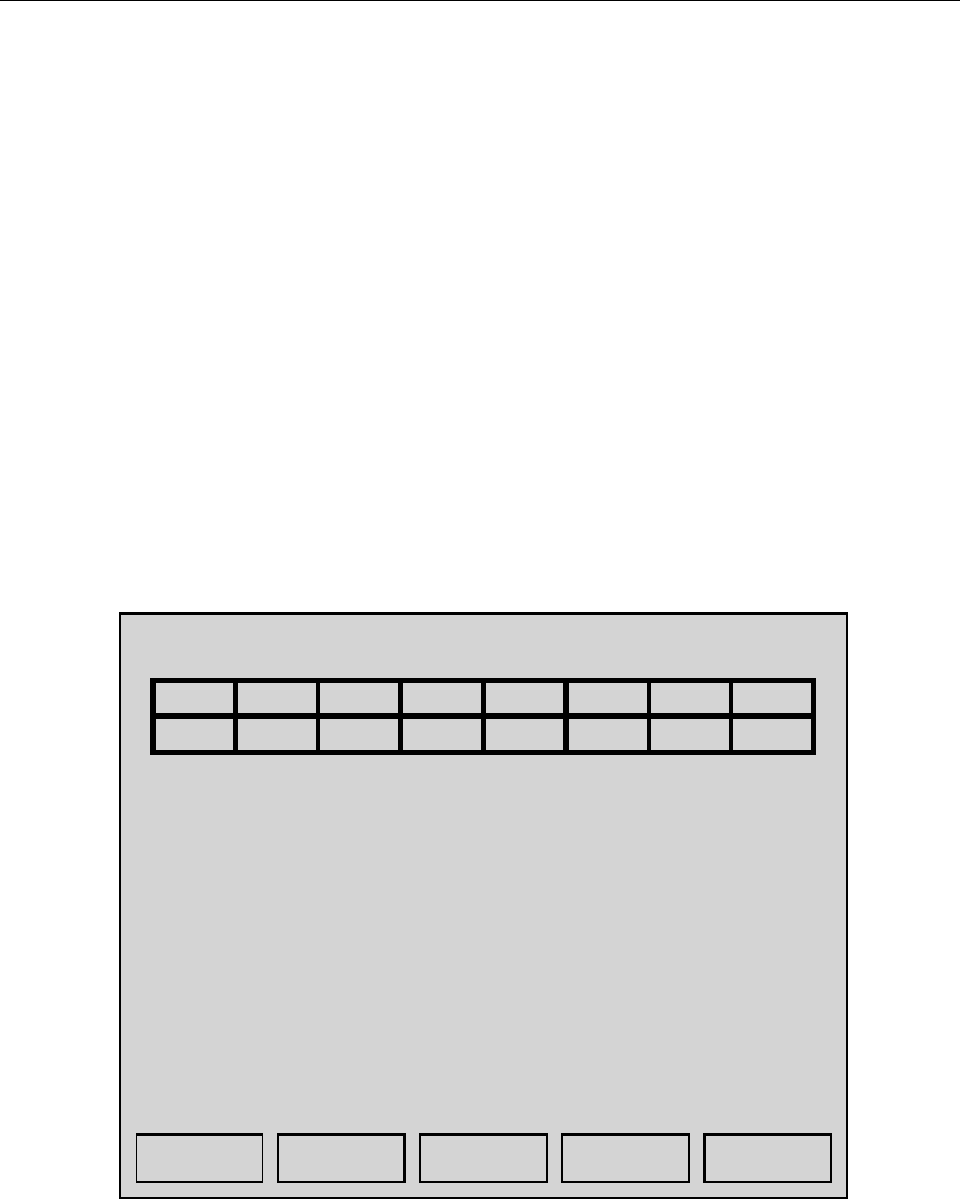
The Frequency Control menu, shown in figure 12 below, enables complete control of
each receiver channel frequency. It also allows control of the transmitter frequency with
the use of a factory password which is obtained by a special request to American Meter
Company. This menu is also used to setup and enable/disable the frequency scan option
on channel 1. The frequency for each channel is displayed in the frequency grid at the top
of the display. The top line of the grid box displays the receiver channel number, and the
bottom line of the grid box displays the frequency applied to that channel. The frequency
display is in the format ?.? which is an abbreviation of 41?.?. For example, if the
frequency display for channel 1 is displaying 3.1, then the frequency programmed into
channel 1 is 413.1. If the frequency display is flashing for any channel, then that
indicates that the channel has not accepted the programmed frequency. The
corresponding green LED on the receiver channel will also be turned off (for additional
information on receiver status indicators, refer to the Transmitter/Receiver Status
Indicator section of the manual). The flashing display is usually a result of an out of
range frequency being programmed into the channel, or because the channel is defective.
The functions available through the frequency control menu are described below:
Figure 12. Sample Frequency Control Menu Screen
FULL (key S): This option allows all receiver frequencies to be setup at
one time by entering a base frequency for channel 1, and then
entering an offset frequency that will be applied to each successive
channel. Once the ‘S’ key is pressed, a flashing cursor block will
appear over the digit to be changed. Simply press a key 0-9 or
press the ‘Q’ key to abandon any changes.
Receiver / Transmitter Frequency Setup
12345678
3.0 3.3 3.6 3.9 4.2 4.5 4.8 5.1
Chan 1 Scan: On
Enter Lower Scan Limit: 41?.? MHz
Enter Upper Scan Limit: 41?.? MHz
Enter Base Frequency: 41?.? MHz
Enter Chan Spacing: ?.? MHz
FULL REDO XMIT QUIT SCAN

Chapter 4 Operation
REDO (key R): This option simply re-initializes each receiver channel with
the frequencies displayed in the frequency grid.
XMIT (key T): This allows the factory-set transmitter frequency to be adjusted.
This command requires a special password acquired from
American Meter Company to enable operation.
QUIT (key Q): As with most menus, this exits out of the current menu.
SCAN (key H): This option is used to enable or disable the frequency scan
option for channel #1, and allows the range of the frequency
scan to be set. Upon pressing the ‘H’ key, The ON/OFF field of
the scan control line contains a flashing cursor. Pressing the ‘0’
key disables the scan feature, and pressing the ‘1’ key enables it.
If the scan control is enabled, then two additional lines will appear
below the scan control status line. Pressing the ENTER key will
move the cursor to the lower scan limit line. Enter the frequency
here as with other frequency control entries. Pressing ENTER
again will move the cursor to the upper scan limit line, which by
default is set to the first channel below the lowest frequency
enabled on channels 2-8. Pressing the ENTER key a final time
will finish the scan control data entry. Any time the frequency scan
option is enabled, a flashing ‘S.S’ will appear in the frequency
grid for channel 1 to indicate that the frequency for channel 1
is constantly changing.
Keys 1-8: Pressing any of these keys will invoke the individual frequency
control entry. This allows for a single receiver channel to be
programmed to an arbitrary frequency, without disturbing the
frequencies of any other channel.
Chapter 4 Operation
Set Perm Menu (backspace key)
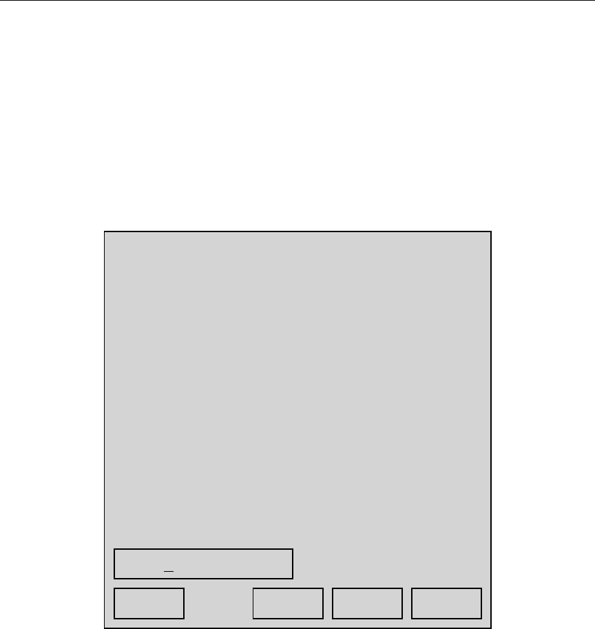
This menu displays and allows control of all permanent settings stored in special non-
volatile memory. Settings found in this menu never need to be loaded from the floppy
disk, and typically never need changed. Special items such as the MMI electronic serial
number, usage statistics, receiver delay parameters, licensed transmitter frequency, and
service history are shown in this menu, an example of which is shown in Figure 13.
Non-authorized users may display this page, but may not modify any of the parameters.
To change any of the settings, the menu must be unlocked by pressing the ‘T’ key and
entering the factory unlock password.
Figure 13. Set Perm Menu Display
Permanent Settings *LOCKED*
1) S/N: 000000122
2) Usage: 000006041
3) Update: 100197:142358
4) Last svc: 000000
5) 2ndG_dly: 9230
6) 3rdG_dly: 9530
7) 4thG_dly: D000
8) Transmit: 4??.???
9) Encrypt: F23A99C6
0) S_PWD: 12345678
P:001
UNLC
K
QUIT
0123456789ABCDEF
<-- -->
Chapter 4 Operation
Quit Command
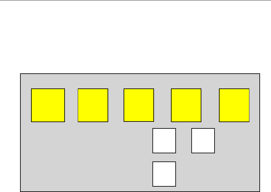
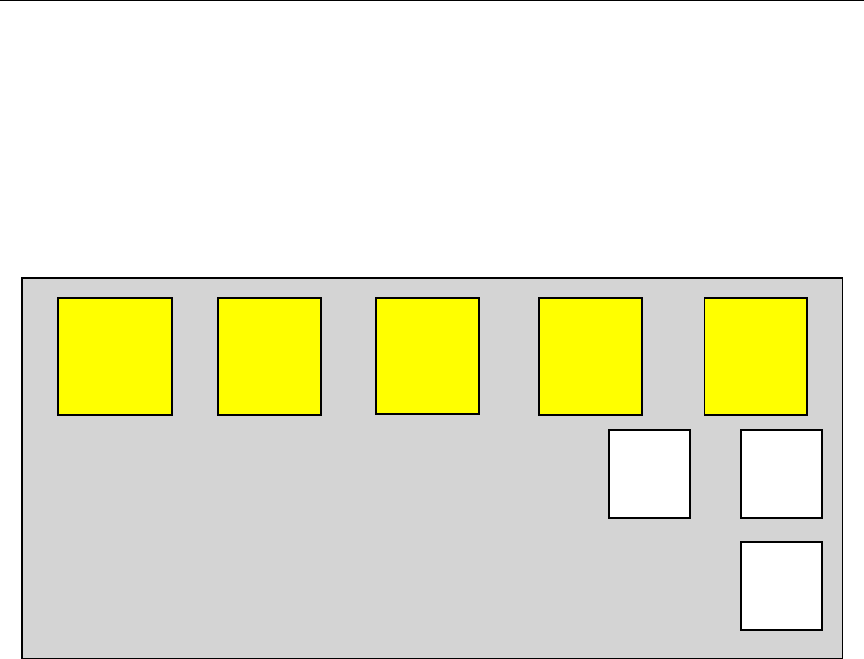
The Quit command consists of three menus which are used to conclude or pause the
execution of a route. Figure 14 is an example of the Quit command. An explanation of
each sub-menu is given in the remainder of this section.
Figure 14. Quit Command Sub-menus
Save & Exit
The Save & Exit option is used to save the results of the current route to floppy disk, and
then exit the menu system. Before the route is saved, the floppy is checked for available
disk space, and then either the route is saved, or the user is prompted to insert a disk with
adequate storage space. Once the save is complete, the next time the MMI is used, it will
attempt to load in a new route from disk. This option may be used at any time during a
route, even if no or few readings have been collected.
Note: After saving a given route, the route data is still stored in backup memory until it
is overwritten by subsequent route data.
Break
The Break option is used to pause the execution of the current route. This allows the user
to completely shut down the MMI, then restart it at a later time, continuing the active
route. The route information that was initially loaded from floppy disk is stored in the
backup memory, and this is the data that the MMI uses while executing a route. Even if a
different floppy disk is inserted into the MMI during the break, the current route will still
be resumed. If the user wishes to abort the reading of a route after returning from a break,
the MMI must be powered on and then an Exit or Save&Exit command may be issued.
SUMMARY READING TOOLS QUIT HELP
EXIT
BREA
K
SAVE
& EXIT

Chapter 4 Operation
Exit
The Exit option is used to exit out of the current route without saving it to floppy disk.
After this option is used, the MMI will load a new route from disk the next time it is
powered up. This option may be used at any time during a route, even if no or few
readings have been collected.
Note: Even though the Exited route was not saved to disk, the entire route is still saved
in the backup memory, and will remain there until it is overwritten by subsequent route
data.
Chapter 4 Operation
Help Command
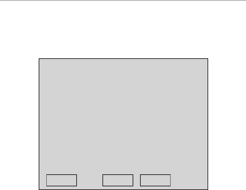
The Help command is used to display a brief on-line operation guide (Quick Manual),
current vehicle position, to view or set the time/date (Loc & Time), and to execute and
view self-check results, as well as display the firmware revision currently executing
(About MMI). Figure 15 shows the Help sub-menus. Both sub-menus are described in
more detail below:
Figure 15. Help Command Sub-menus
Quick Manual
The Quick Manual option will display several pages of brief descriptions of various MMI
commands and transponder statuses. The user may scroll up or down through the
manual, and exit from any page. The quick manual menu is intended to be used as a
quick reference, not a complete guide. For detailed operating instructions and
explanations, please consult the appropriate section of this manual.
SUMMARY READING TOOLS QUIT HELP
ABOUT
MI QUICK
Manual
LOC &
TIME
Chapter 4 Operation
Location & Time
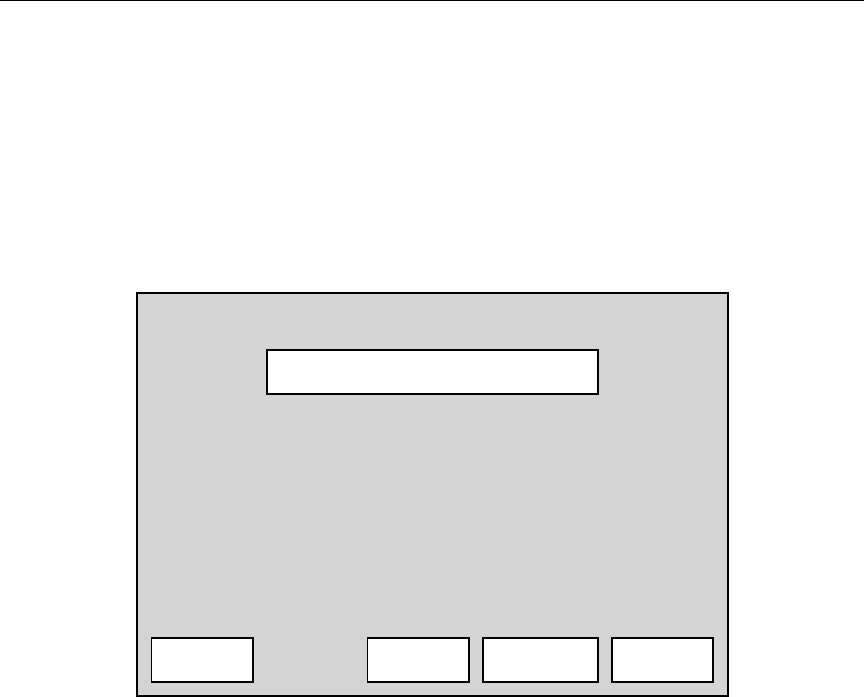
The Location & Time menu displays GPS navigation information as well as the current
system time and date. This menu also allows the GPS, time, and date information to be
changed. An example of the Location & Time menu is displayed in figure 16.
Figure 16. Location & Time Menu Display
As shown in figure 16, Both GPS and system time are displayed. The top of the display
details current GPS navigation system status. The GPS status indicator may one of three
statuses:
No Response: This indicates that there is no data being received from the GPS
receiver by the MMI.
No Position: This indicates that the MMI is receiving data from the GPS receiver,
but there are not enough satellites in view to navigate with.
Active: This is the normal status indication that the MMI is receiving data from
the GPS receiver, and the receiver is producing good Lat/Lon position
data.
The next lines on the display show the current system date as well as both system and
GPS time. The GPS UTC time is in a format known as universal time coordinated (UTC)
which is a world-wide time. Depending on the location in the U.S., UTC time is a few
hours ahead of local time. UTC time is extremely accurate, as it is derived from atomic
clocks abord the GPS satellites.
Location & Time
GPS: No Response
GPS Sats: 0
GPS DOP: 0.0
System Time: 08:24:47
System Date: 10-29-97
GPS UTC Time: 13:25:16
GPS Latitude: 38.1345
GPS Longitude: 81.5516
Time GPS QUIT
Chapter 4 Operation
The current system date and time may also be adjusted from with the Loc & Time display
using the Time option by pressing the ‘S’ key. This will invoke the display shown in
figure 17. New time or date digits are simply pressed on the handheld terminal, and the
two arrow keys moves the flashing cursor over top of the digit to be changed. Also, the
system time and date may be synchronized to the GPS UTC time and date by using the
UTC option (key ‘T’). It should be noted, that in the U.S., UTC time will not match local
time. Pressing the ‘Q’ key exits back to the Loc & Time menu.
Figure 17. Set Time & Date Menu Screen
Set System Time & Date
Use the S & H keys to select the digit
you wish to change. Press the ENTER key
to set the time, or press the Q key to
abandon changes.
08:24:47 10-29-1997
<-- QUIT -->UTC

Chapter 5 Troubleshooting
Troubleshooting
This section offers brief suggestions to try in the event that the MMI is not functioning
properly. The only items covered in this section are those which are user serviceable, or
those which the operator is responsible for properly setting up or checking during
operation.
•
••
•
Handheld terminal does not turn on, or does not respond.
First verify that there are no illuminated and non-flashing red LED’s on any of the
main computer boards at the upper left of the MMI. If nothing seen, then
inspect that the main power cable is correctly connected. If there no obvious
cabling problems, then the two internal fuses should be checked.
These may be found just inside the rear cover door of the MMI which is opened
by removing three small screws. There is a separate fuse holder for the external
power connection as well as for the internal battery. These fuses are standard
automotive types. Replace with a 20-amp fuse.
•
••
•
Poor reading performance or range.
This should be verified by using the Troubleshoot menu contained within the
Tools command. Using a known good transponder, if it is verified that the transponder
is difficult to communicate with, then check both antennas. The whip section of
each antenna should be screwed down tightly to the base, and the transmit antenna
must be screwed on the MMI connector until tight. Also verify that all the
green PLL OK LED’s are illuminated on the transmitter and receiver boards.
Also verify that both RF amplifier LED’s are illuminated.
•
••
•
Uninitialized transponders are not read in GEO mode.
Using the System Setup menu contained within the Tools command, verify that
the minimum GEO mode signal strength requirement is not set too high. As a
check, this value may be set to 0 to disable the requirement.
•
••
•
Transponders are able to be read in FIFO mode, but not in L/L mode.
Verify that the GPS has an active status. If so, then turn off the dynamic window
feature, then check the interrogation window size using the System Setup menu in
the Tools command. As a check, this value may be set to 20 to use a 2000-foot
window radius. If this still fails to produce readings in L/L mode, then verify that
the MMI considers the transpoders in question to be within range by using the
UNRD summary menu. This will display the distance between each unread
transponder and the MMI. If the displayed distance is not what is expected, then
the Lat/Lon coordinates for the transponders in question may be unitialized, or
invalid.

Appendix A File Formats
File Formats
The MI requires three important disk files for operation. These files consist of operating
parameters and transponder data which is usually generated with a PC, but may be
created with any system capable of accessing a 1.44Meg PC-formatted floppy disk.
Normally the first two files, the Start and Guide files are not altered or re-created. They
may be simply copied from a master source each time they are needed. The Reading.rte
file contains the transponder information, which is usually created from a larger database
of transponder data, and only the transponders for a particular route are extracted and
placed in the file. The MMI also creates an output file ending with the extension .VAN
which contains transponder output data. This data in this file is typically read back into
the master database, and then erased off the floppy.
The Start File
The start. file is used by the operating system, and contains directions used only during
power-up.
The GUIDE File
The GUIDE file contains system operation parameters that control how the MMI
operates. Each of these parameters may be displayed and changed while the MMI is
operating by using the System Setup option from the Tools command. A typical GUIDE
file configuration might look like this :
0 1 1 1 15 0 000 123456 1 1 1 1 2.0 3.0
where:
1st entry: The mode of interrogation. 0 = Lat/Lon, 1 = FIFO, 2 = GEO.
2nd entry: The option to display good reads. 0 = No, 1 = Yes.
3rd entry: The option to send a beep with each good read. 0 = No, 1 = Yes.
4th entry: The option to reset any tamper indications. 0 = No, 1 = Yes.
5th entry: The interrogation window size in hundreds of feet (15 = 1500 feet).
Range: 1-99
6th entry: This entry is not used in the MMI but remains as a place holder.
7th entry: This entry is not used in the MMI but remains as a place holder.
8th entry: The 6-digit password used to access the System Setup and the Set Time
options.
9th entry: The option to sort summary unread display. 0 = No, 1 = Yes.
10th entry: The dynamic window option enable. 0 = No, 1 = Yes.
11th entry: Option to reject reads with checksum errors. 0 = No, 1 = Yes.
12th entry: Frequency scan option enable. 0 = No, 1 = Yes.
13th entry: Lower scan limit frequency in the format 41?.?.
14th entry: Upper scan limit frequency in the format 41?.?.

Appendix A File Formats
The READING.RTE File
The data in the Reading.rte file specifies what transponders are to be read. This data
contains the transponder serial number, latitude, longitude, and street address. The
latitude and longitude are used when the MI is in the Lat/Lon or GEO modes of
interrogation. The list of transponders loaded from disk may be examined at any time by
using the options under the Summary command. This file is usually created from a
larger, more centralized database using TICS, however it may be created using any means
available. The Reading.rte file consists of an input header, followed by up to 10000
transponder entries. The format of the input file must be strictly adhered to, as even a
single character out of place will corrupt the file. The file format is shown below, and
Figure 20 is a sample Reading.rte file listing.
route name latitude longitude file creation
date total record
count
columns 1-3 5-10 12-17 19-24 26-30
width 3 6 6 6 5
type characters hexadecimal hexadecimal decimal decimal
Figure 18. READING.RTE input file header format
serial
number latitude longitude street
address place
identifier
columns 1-7 9-14 16-21 23-41 43-45
width 7 6 6 19 3
type decimal hexadecima
lhexadecima
lcharacters characters
Figure 19. READING.RTE input file record format:
Notes: 1. The latitude and longitude in the file header may be the Lat/Lon of the
place where the file was created. This is for reference only.
2. The latitude and longitude are stored as 24-bit binary quantities known
as BAMS which stands for Binary Angular Measurements. This is a
format which allows a number consisting of degrees, minutes, and seconds to be
stored as a binary equivalent number. The binary format is faster and
easier for the MI to work with. A BAMS number is created as follows:
BAMS = ( Total degrees ÷ 360 ) × 16777216
Total degrees = Degrees + ( Minutes ÷ 60 ) + ( Seconds ÷ 3600 )

Appendix A File Formats
Example: Degrees/Minutes/Seconds value: 38° 27' 06"
Total degrees = 38 + ( 27 ÷ 60 ) + ( 06 ÷ 3600 )
Total degrees = 38.4517 (round result to 4 places right of the decimal)
BAMS = ( 38.4517 ÷ 360 ) × 16777216
BAMS = 1791979 decimal -or- 1B57EB hexadecimal
Figure 20. READING.RTE Example File Format
AMR,1C5852,358B16,100292,00006
0011758,1B57EB,3A42A0,84 ERSKINE LANE ,WVA
0011486,1B57EB,3A42A0,86 ERSKINE LANE ,WVA
0012061,1B57EF,3A42A2,101 E. MAIN STREET,WVA
0010783.1B57F0,3A42A2,123 E. MAIN STREET,WVA
0011578,1B5921,3A43B3,96 VALLEY VIEW DR,WVA
0011499,1B5A04,3A43C1,140 CASCADE DR ,WVA

Appendix A File Formats
The .VAN Output File
Each time the MMI Save & Exit command is used, an output file is created on the floppy
disk. This file contains transponder information such as the meter reading, the receiver
channel activity, and the status code. This file, like the Reading.rte file, has a header
followed by a variable number of transponder records. The actual filename used for this
file is built from a combination of the route name stored in the Reading.rte file, the
system month and day, and if needed, a single letter suffix. This method of filename
creation allows for the same route to be read multiple times using the same disk, without
overwriting data from the previous route file. If the floppy disk is full when a .van file is
to be written, the MMI will prompt for a disk change. The format of the .van file is
shown below, and Figure 23 is a sample .van output file listing.
route name record
count file date load date load time quit date quit time
columns 1-3 5-9 11-16 18-23 25-30 32-37 39-44
width3 5 66666
type characters decimal decimal decimal decimal decimal decimal
Figure 21. VAN Output File Header Format
serial number status code reading latitude longitude channel activity time
columns 1-7 9-10 12-19 21-26 28-33 35-40 42-48
width 7 2 8 6 6 6 6
type decimal hex decimal hex hex hex decimal
Figure 22. VAN Output File Record Format
Notes: 1. See Table 1 for the definition of the status codes.
2. The Channel activity has a bit for each receiver channel that passed the BCH
check.
Figure 23. VAN Output File Sample Listing
AMR,00006,100292,100392,133504,100392,150143
0011758,01,00000127,1B57EB,3A42A0,03FC0C,134003
0011486,01,00000035,1B57EB,3A42A0,0FFF0C,134514
0012061,07,00000089,1B57EF,3A42A2,01B80C,135055
0010783.01,00000039,1B57F0,3A42A2,00FF0C,135632
0011578,0B,00000008,1B5921,3A4300,01FFCC,140224
0011499,01,00000104,1B5A04,3A43C1,03EB0C,144312

Appendix B Specifications
Specifications
Power Source: 12 VDC Vehicle Power / Sealed Internal Gel-Cell Battery
Power Consumption: 120 Watts (10 Amps maximum current) fully loaded
RF Transmitter: 5 Watts Nominal Power, Software Tunable
RF Receiver: 8 Independent Channels, Software Tunable,
-106 dBm sensitivity
FCC Compliance: Part 90:63 / FCC ID: G8JVAN01
Operating Temperature: -5ºF to +160ºF Package Temperature
-4ºF to +140ºF Handheld Terminal
Storage Temperature: -40ºF to +185ºF Package Temperature
-4ºF to +140ºF Handheld Terminal
Humidity: 5% to 95% Non condensing
Size: ???????????????
Weight: (Approximate) 60 lbs.