Elster Solutions MNIC Mini Network Interface Card User Manual 72124703 Manual MNIC
Elster Solutions, LLC Mini Network Interface Card 72124703 Manual MNIC
Manual

2320 Presidential Drive, Suite 101, Durham, NC 27703 USA Voice: 919-381-4235
Certification Exhibit
FCC ID: QZC-MNIC
IC: 4557A-MNIC
FCC Rule Part: 15.247
ISED Canada’s Radio Standards Specification: RSS-247
TÜV SÜD Project Number: 72124703
Manufacturer: Elster Solutions
Model: MNIC
Manual
A3 ALPHA® with SynergyNet® communications
For use with the SynergyNet NIC option board
IL42-4047A
GENERAL
This leaflet provides general information for the SynergyNet network interface card communication (NIC) option for the
A3 ALPHA meter. For information on installing the A3 ALPHA meter, see the ALPHA meter installation instructions (IL42-4001S
or later).
The A3 ALPHA meter may be ordered with the SynyergyNet NIC option board, which provides 900 MHz ISM band
communications. Additional hardware configurations may include either a relay option board or an interrupter control board for
standard ALPHA meters.
Typically, the internal antenna used with the SynyergyNet NIC option board is sufficient for reliable communication with the
SynergyNet network. However, if the A3 ALPHA meter is enclosed in a metal service cabinet or the antenna needs to be mounted
higher to increase communication distances, an external antenna may be used.
This leaflet contains general information for installing the A3 ALPHA meter equipped with connections for an external antenna.
For information on the operation of the A3 ALPHA meter, see the A3 ALPHA meter technical manual (TM42-2190C or later) or
the A3 ALPHA meter technical manual for use in Canada (TM42-2195C or later).
WARNING
!
Use authorized utility procedures to install and service metering equipment. Dangerous voltages are present. Equipment
damage, personal injury, or death can result if safety precautions are not followed.
Use circuit closing devices on current transformer secondaries (3S, 4S, 5S, 5A, 6S, 6A, 8S, 9S, 10S, 10A, 26S, 29S, 35S, 36S,
and 36A meters). Equipment damage, personal injury, or death can result if circuit closing secondaries are not used.
LOCATION OF ANTENNAS
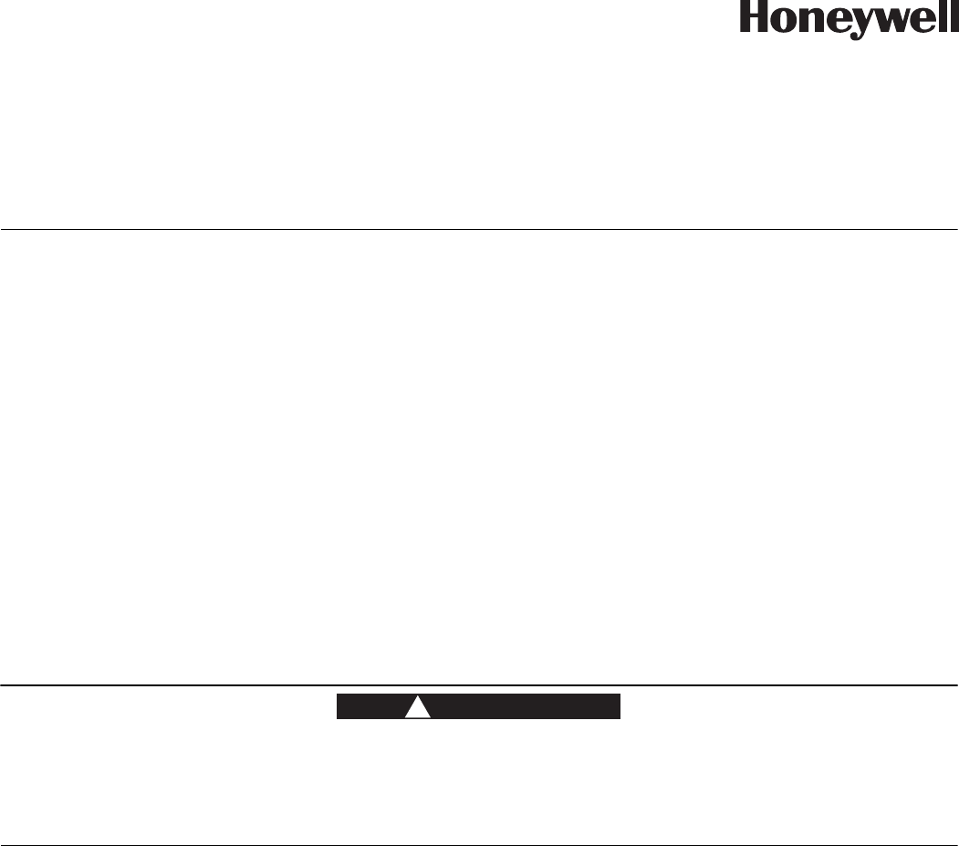
See Figure 1 for the location of the SynergyNet NIC internal antenna.
The SynergyNet NIC internal antenna is fix-mounted to the periphery of the A3 ALPHA meter’s electronic housing. The
SynergyNet NIC antenna is not adjustable or removable.
Alternatively, A3 ALPHA meters may be ordered with an external SynergyNet NIC antenna. With this option, the meter is shipped
with an RF “pigtail” output cable which allows connection to an antenna external to the meter. This is advantageous in locations
with lower signal strength.
A3 ALPHA® with SynergyNet® communications 2
Figure 1. Location of internal antenna
CONNECTING AN EXTERNAL ANTENNA
NOTICE
Installation of an external antenna must be performed by a utility company professional meter installer or contract personnel
hired by the utility company to perform electricity meter installation.
WARNING
!
Use approved utility safety procedures while installing the external antenna and meter RF output cable in the meter socket
box. Dangerous voltages may be present. Assure that there is sufficient clearance between any line-energized socket part
and the exposed metal of the antenna connectors. Also assure that the external antenna is electrically bonded to the meter
socket box. Failing to follow approved utility safety procedures, failing to allow sufficient clearance, or failing to electrically
bond the external antenna to the meter socket box may result in equipment damage, personal injury, or death.
The A3 ALPHA meter with the SynergyNet NIC option board has been certified for operation with the following antennas.
Antennas not included in this list are strictly prohibited for use with this device.
• Internal antenna: Honeywell Smart Energy electricity metering P/N: 1B12150H01
• Local external antennas: Laird/Antenex TRA9023P (3.1 dBi) for use only with metal service cabinets and meter sockets;
Laird/Antenex TRA9023NP (3.1 dBi) for use only with non-metal service cabinets
• Remote external antennas: PCTEL/MAXRAD P/N MFB9150 (2.15 dBi); PCTEL/MAXRAD P/N MFB 9153 (5.15 dBi)
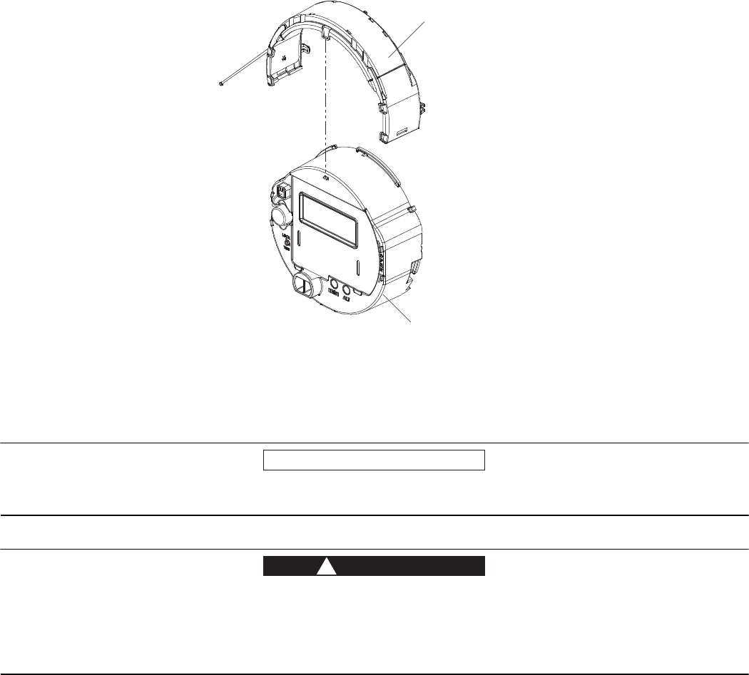
The external antenna connects to the SynergyNet NIC option board using a connector lead as shown in Figure 2. There are two
options available for connecting an external antenna:
• Local external antenna
• Remote external antenna
SynergyNet NIC
internal antenna
A3 ALPHA meter
electronic assembly
A3 ALPHA® with SynergyNet® communications 3
Figure 2. Retaining clip and connector lead
LOCAL EXTERNAL ANTENNA
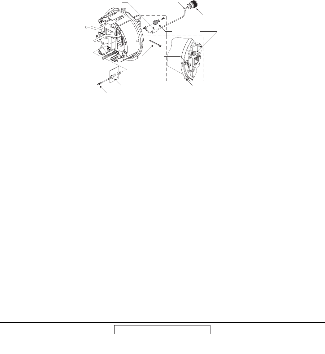
If the A3 ALPHA meter is used in a metal service cabinet, using a local external antenna may be necessary. To obtain better
coverage, the local external antenna can be mounted on the top of the metal service cabinet or the meter socket enclosure (see
[1] in Figure 3).
Honeywell Smart Energy recommends the Laird/Antenex 902-928 MHz permanent mount antenna (TRA9023P).
See Figure 3 for the recommended location of the SynergyNet NIC external antenna. Honeywell Smart Energy recommends
mounting the external SynergyNet NIC antenna on the top of the meter socket box as shown, centered in the available space on
the meter box’s top surface.
• Drill a 5/8-inch hole into the cabinet wall with a step drill and/or punch the specified antenna mounting hole in the top of
the meter socket box and install the antenna using the antenna manufacturer’s instructions.
• Connect the meter's RF “pigtail” output cable directly to the antenna via its integral N-type connector. The SynergyNet NIC
antenna output cable may be ordered in two lengths: 19 or 36 inches. Choose the length based on the distance from the
meter to the SynergyNet NIC external antenna, which is in turn determined by the size of the meter socket box.
For installations where the mounting of the local antenna does not provide a conductive metallic ground plane, the Antenex
TRA9023NP (no ground plane required) may be employed. The gain and pattern are virtually identical with the TRA9023P
version. The TRA9023NP antenna may also be employed on metallic ground planes with good results.
REMOTE EXTERNAL ANTENNA
If the A3 ALPHA meter is used in a metal building, or the meter is installed in a location where the site requires an antenna at a
greater height, a remote antenna may be used. If a remote external antenna is used, a lightning/surge arrestor should be
installed at the bottom of the socket enclosure (see [2] in Figure 3). Honeywell Smart Energy recommends a PolyPhaser DSXL
IN-LINE EMP surge filter (Tessco P/N 491574).
NOTICE
Do not use a standard RG-8/U cable with solid polyethylene dielectric. The losses in solid dielectric RG-8/U cables in short
distances make solid dielectric RG-8/U cables unacceptable.
The most economical connection to the remote external antenna is the RG-8/U “foam” or “LMR-400” type cable. This type of
cable is suitable for distances of up to 100 feet. The foam dielectric cable will incur a loss of approximately 3.9 dB in 100 feet (or
approximately 2 dB in 50 feet). The coaxial cable should be mounted at the bottom of the meter socket in “drip loop” fashion. A
“drip loop” is formed by bringing the coaxial cable to a point below the meter socket and then bending it back up to the
connector. This forms a U-shape, which allows water to run down the cable exterior. Antenna cables should be ordered with N-
type male connectors on each end.
External antenna
connection lead
N-type connector
to external antenna
Antenna cable
Retaining clip
Ferrite bead
Connector lead
Antenna isolation board
Wire tie
A3 ALPHA® with SynergyNet® communications 4
The A3 ALPHA meter with the SynergyNet NIC option board has been certified for operation with the following remote external
antennas. Both antennas are rated to withstand 100 mph winds and are fitted with Type N female connectors:
• PCTEL/MAXRAD MFB9150 Series (Tessco P/N 39493) for unity gain (2.15 dBi)
• PCTEL/MAXRAD MFB9153 Series (Tessco P/N 74330) for 3 dB gain (5.15 dBi)
Regardless of the antenna selected, the antenna should be mounted with at least two MMK1 pipe clamps (Tessco SKU 68869).
The antenna should be mounted in the clear, as free from conductive or metallic obstructions as possible. The connectors
should be sealed for waterproofing.
Please note that external antennas must be purchased separately, either from Honeywell Smart Energy or a third party, from a
list of approved antennas. Please ask your Honeywell electricity metering sales representative for the current list of approved
external antennas.
Figure 3. Location of SynergyNet NIC external antennas
Remote antenna materials described in this IL can be obtained from the following:
Tessco Technologies, Inc.
11126 McCormick Road
Hunt Valley, MD 21031-1494
+1 800 508 5444
tessco.com
Laird/Antenex antennas can be obtained from the following:
OEM Sales M6
Laird Technologies
1751 Wilkening Court
Schaumburg, IL 60173
+1 847 839 6916 (telephone) or +1 847 839 6063 (fax)
www.lairdtech.com
Local external antenna installation Remote external antenna installation
[1] External antenna
[2] Lightning/surge
arrestor
N-type female connector for
cable to remote external antenna
A3 ALPHA® with SynergyNet® communications 5
FCC AND ISED CANADA COMPLIANCE
WARNING (PART 15.21)
The A3 ALPHA meter equipped with the MNIC option complies with Part 15 of the FCC Rules and with Innovation, Science, and
Economic Development (ISED) Canada RSS-210. Warning: Changes or modifications not expressly approved by Honeywell
could void the user's authority to operate the equipment.
USER INFORMATION (PART 15.105)
This equipment has been tested and found to comply with the limits for a Class B digital device, pursuant to part 15 of the FCC
Rules. These limits are designed to provide reasonable protection against harmful interference in a residential installation. This
equipment generates, uses and can radiate radio frequency energy and, if not installed and used in accordance with the
instructions, may cause harmful interference to radio communications. However, there is no guarantee that interference will not
occur in a particular installation. If this equipment does cause harmful interference to radio or television reception, which can
be determined by turning the equipment off and on, the user is encouraged to try to correct the interference by one or more of
the following measures:
• reorient or relocate the receiving antenna
• increase the separation between the equipment and the receiver
• connect the equipment into an outlet on a circuit different from that to which the receiver is connected
• consult the dealer or an experienced radio/TV technician for help
If you experience trouble with this equipment, please use the Return Material Request (RMR) feature available at the Online
Customer Services at www.elsterelectricity.com. Do not attempt to repair this equipment yourself unless you are replacing the
entire module.
COMPLIANCE STATEMENT (PART 15.19)
This device complies with Part 15 of the FCC Rules and Class B digital apparatus requirements for ICES-003. Operation is
subject to the following two conditions: (1) This device may not cause harmful interference, and (2) this device must accept any
interference received, including interference that may cause undesired operation of the device.
ÉNONCÉ DE CONFORMITÉ
Cet appareil est conforme à la Partie 15 des règles de la FCC et aux CNR d'Industrie Canada applicables aux appareils radio
exempts de licence. L'utilisation de cet appareil est soumise aux deux conditions suivantes : (1) Cet appareil ne doit pas
provoquer d'interférences nocives et (2) cet appareil doit accepter toutes les interférences reçues notamment celles pouvant
provoquer un fonctionnement intempestif de l'appareil.
ANTENNA COMPLIANCE
Under Industry Canada regulations, this radio transmitter may only operate using an antenna of a type and maximum (or lesser)
gain approved for the transmitter by Industry Canada. To reduce potential radio interference to other users, the antenna type
and its gain should be so chosen that the Equivalent Isotropic Radiated Power (EIRP) is not more than that necessary for
successful communication.
Conformément à la réglementation d'Industrie Canada, le présent émetteur radio peut fonctionner avec une antenne d'un type
et d'un gain maximal (ou inférieur) approuvé pour l'émetteur par Industrie Canada. Dans le but de réduire les risques de
brouillage radioélectrique à l'intention des autres utilisateurs, il faut choisir le type d'antenne et son gain de sorte que la
puissance isotrope rayonnée équivalente (p.i.r.e.) ne dépasse pas l'intensité nécessaire à l'établissement d'une communication
satisfaisante.
SynergyNet NIC: This radio transmitter has been approved by Industry Canada to operate with the antenna types listed below
with the maximum permissible gain indicated. Antenna types not included in this list, having a gain greater than the maximum
gain indicated for that type, are strictly prohibited for use with this device.
A3 ALPHA® with SynergyNet® communications 6
DISCLAIMER OF WARRANTIES AND LIMITATIONS OF LIABILITY
There are no understandings, agreements, representations, or warranties either express or implied, including warranties of merchantability or fitness for a particular
purpose, other than those specifically set out by any existing contract between the parties. Any such contract states the entire obligation of the seller. The contents of
this document shall not become part of or modify any prior existing agreement, commitment, or relationship.
The information, recommendations, descriptions, and safety notices in this document are based on Elster Solutions, LLC experience and judgment with respect to
operation and maintenance of the described product. This information should not be considered as all-inclusive or covering all contingencies. If further information is
required, Elster Solutions, LLC should be consulted.
No warranties, either expressed or implied, including warranties of fitness for a particular purpose or merchantability, or warranties arising from the course of dealing or
usage of trade, are made regarding the information, recommendations, descriptions, warnings, and cautions contained herein.
In no event will Elster Solutions, LLC be responsible to the user in contract, in tort (including negligence), strict liability or otherwise for any special, indirect, incidental, or
consequential damage or loss whatsoever, including but not limited to: damage or loss of use of equipment, cost of capital, loss of profits or revenues, or claims against
the user by its customers resulting from the use of the information, recommendations, descriptions, and safety notices contained herein.
© 2017 by Honeywell International Inc. All rights reserved.
Honeywell Smart Energy Americas
Raleigh, North Carolina
Technical support: 800 338 5251
SynergyNet NIC: Le présent émetteur radio a été approuvé par Industrie Canada pour fonctionner avec les types d'antenne
énumérés ci-dessous et ayant un gain admissible maximal et l'impédance requise pour chaque type d'antenne. Les types
d'antenne non inclus dans cette liste, ou dont le gain est supérieur au gain maximal indiqué, sont strictement interdits pour
l'exploitation de l'émetteur.
• Honeywell (1B12150H01): 3.49 dBi
• Laird/Antenex TRA9023P(NP) (white body) or TRAB9023P(NP) (black body): 3 dBi
• PCTEL/MAXRAD MFB9150 unity gain Fiberglass omnidirectional: 2.15 dBi
• PCTEL/MAXRAD MFB9153 3 dB Fiberglass omnidirectional: 5.15 dBi
This device complies with Industry Canada’s licence-exempt RSSs. Operation is subject to the following two conditions:
(1) This device may not cause interference; and
(2) This device must accept any interference, including interference that may cause undesired operation of the device.
Le present appareil est conforme aux CNR d’Industrie Canada applicables aux appareils radio exempts de licence. L’explotation
est autorisée aux deux conditions suivantes: (1) l’appareil ne doit pas produire de brouillage, et (2) l’utilisateur de l’appareil doit
accepter tout brouillage radioélectrique subi, même si le brouillage est susceptible d’en compromettre le fonctionnement.
RF RADIATION SAFETY GUIDELINES
This equipment complies with radiation exposure limits set forth for an uncontrolled environment. This equipment should be
installed and operated with minimum distance 31 cm between the radiator and your body. This transmitter must not be co-
located or operating in conjunction with any other antenna or transmitter.
DIRECTIVES DE SÉCURITÉ DE RADIOFRÉQUENCE
Cet équipement est conforme aux limites d'exposition aux radiations dans un environnement non contrôlé. Cet équipement
doit être installé et utilisé à distance minimum de 31 cm entre le radiateur et votre corps. Cet émetteur ne doit pas être co-
localisées ou operant en conjunction avec tout autre antenne ou transmetteur.
COLLOCATION STATEMENT
Collocation of simultaneously-transmitting (co-transmitting) antennas located within 20 cm of each other within a final
product is not allowed, except as documented in the FCC application. Users and installers must be provided with antenna
installation instructions and transmitter operating conditions for satisfying RF exposure compliance.