Elster Solutions REXILC 900 MHz Automated Meter Reading System Transmitter User Manual PG42 1005 p65
Elster Solutions, LLC 900 MHz Automated Meter Reading System Transmitter PG42 1005 p65
User Manual

A3 ALPHA® Meter/Collector
Product Guide PG42-1005A

A3 ALPHA Meter/Collector PG42-1005A
2July 2003
The A3 ALPHA meter/collector is the communications point between the
EnergyAxis System and the local network of REX meters that are registered to
the meter/collector. The EnergyAxis System communicates with the A3 ALPHA
meter/collector using a standard telephone line. The A3 ALPHA meter/collector
then communicates with its registered REX meters using a 2–way, 900 MHz radio
frequency network. The A3 ALPHA meter/collector is responsible for various
activities within the network of REX meters, including the following:
■reading and storing the billing data from each REX meter on a periodic basis
■reading and storing the load profiling data from a configurable number of
REX meters on a periodic basis
■notifying the REX meters to perform demand resets based on a schedule
from the EnergyAxis System
■reading and storing the previous billing period data from REX meters after a
demand reset has occurred
■notifying the REX meters to perform season changes based on a schedule
from the EnergyAxis System
■reading and storing the previous season data from REX meters after season
changes have occurred
■synchronizing the REX meters to the system time and TOU day type
■distributing TOU rate schedules to the REX meters
■reading or sending commands to an individual REX meter on command from
the EnergyAxis System
■performing other network maintenance tasks
■reporting the billing and load profiling data back to the EnergyAxis System
General Description
The A3 ALPHA meter builds upon the strengths of the existing ALPHA meter
designs. Like its predecessors, the A3 ALPHA meter uses Elster Electricity's
patented digital measurement techniques that offer high accuracy, repeatability,
and low ownership costs. In support of open architecture standards, the
A3 ALPHA meter is the first Elster Electricity meter with full ANSI C12.18,
C12.19, and C12.21 communication protocol support.
To function as an A3 ALPHA meter/collector, an A3 ALPHA meter requires the
following two option boards:
■internal telephone modem (ITM3) with optional outage reporting capabilities
■internal LAN controller (ILC1) option board
The ITM3 option board connects to the A3 ALPHA meter using the 20-pin
header (J4) on the meter circuit board as shown in Figure 1. The ILC1 option
board connects to the ITM3 option board using the 20-pin header (J5) as shown
in Figure 1.
An A3 ALPHA meter/collector has a 4-conductor telephone cable exiting the
meter with an RJ-11 connector at the end as shown in Figure 2. There is a wire
marker approximately 6 inches from the RJ-11 end with “INT MOD ITM3” printed
on it for identifying that the ITM3 option board is installed.
A3 ALPHA Meter
Circuit Board
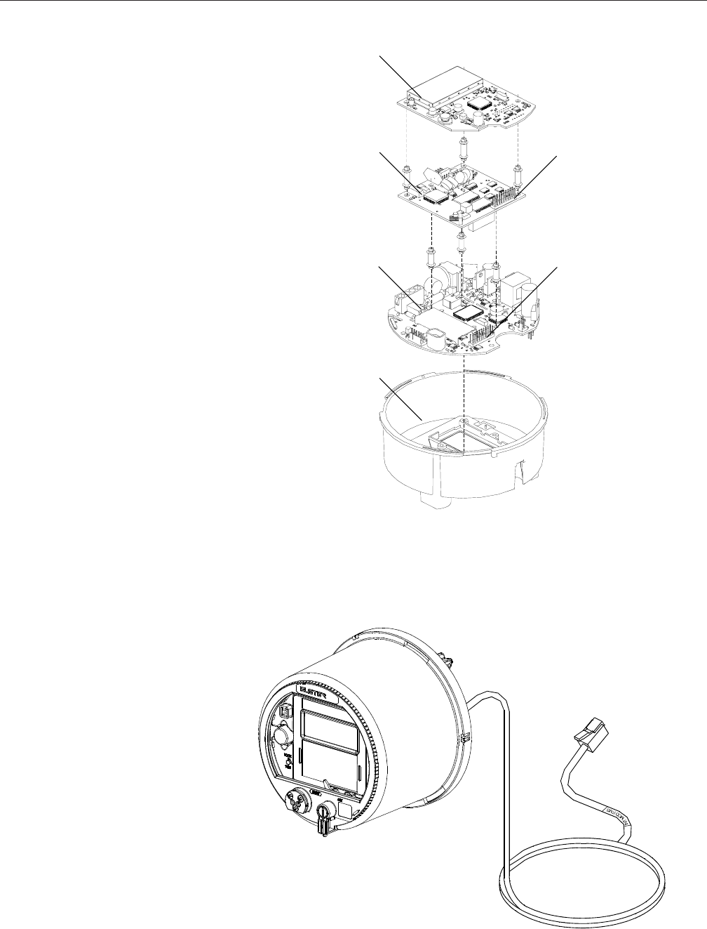
PG421005A A3 ALPHA Meter/Collector
July 2003 3
Meter electronic
housing
Meter circuit
board
ITM3 option
board
ILC1 option
board
J4
J5
Figure 1. A3 ALPHA meter electronic assembly
Figure 2. A3 ALPHA meter with ITM3 RJ-11 cable

A3 ALPHA Meter/Collector PG42-1005A
4July 2003
Metercat Programming Note
To have the A3 ALPHA meter function properly as a data collector in the
EnergyAxis System, it is important that the meter be programmed correctly using
Metercat. In the Remote component tab in Metercat, be sure that the following
options are set:
■Port 1 usage is set to internal modem.
■Port 2 usage is set to direct connect.
■On the Port 1 Modem tab, enable line sharing (the Enable Line Sharing box is
checked).
■On the Port 2 Direct Connect tab, the bit rate is set to 9600.
The other options can be set as desired. For more information on using Metercat,
see the Metercat documentation.
Metercat
The A3 ALPHA meter/collector requires Elster Electricity Metercat support
software release 1.4 or later to program the meter for collecting REX meter data
and read the LAN status and information from the meter. Metercat offers the
following features:
■program development to create user-defined configuration data
■meter programming to send user-defined configuration data or commands to
the meter
■meter reading to receive data that has been stored by the meter
EnergyAxis Metering Automation Server
The EnergyAxis Metering Automation Server (MAS) reads meters over telephone
or wireless networks. Using MAS, meter readings can be scheduled on a periodic
basis or performed on-demand from the browser-based user interface. MAS
allows all billing data to be read from the meter; this includes data from the A3
ALPHA meter/collector and from each REX meter. Billing data includes multi-
channel interval data, consumption, demand, time-of-use registers as well as
meter status flags. REX meter data can be read from the stored data in the A3
ALPHA meter/collector or it can be read directly from the REX meter. MAS
provides several reports to help manage and operate the system.
Data exchange with MAS is performed using an open XML schema, AMR Data
Exchange Format (AMRDEF), so that interfaces with billing systems and other
enterprise systems can be easily implemented. MAS also comes with the
JSlinger module, a powerful driver for file transfer protocol (FTP) that can trans-
form, compress and encrypt data files prior to sending them to trusted IP ad-
dresses across the Internet.
Elster Electricity Meter
Support Software

PG421005A A3 ALPHA Meter/Collector
July 2003 5
The A3 ALPHA meter and the ILC1 option board typically operate independently
of each other. The primary task of the ILC1 option board is to maintain the local
area network (LAN) and read and store billing data from REX meters. The ILC1
option board communicates with the A3 ALPHA meter/collector to read time and
day type information. This information is then propagated through the LAN to the
REX meters. The time base in the A3 ALPHA meter/collector is used as the
system time for the LAN, and the ILC1 option board periodically reads this time
and distributes the time to the LAN.
Billing Date
The billing date (or, the demand reset date) for the A3 ALPHA meter/collector can
be controlled by either of the following:
■internally by the calendar in the A3 ALPHA meter
■externally by MAS when the MAS calls the A3 ALPHA meter/collector on the
billing date and issues a demand reset command
Billing dates for REX meters in the LAN are handled by the ILC1 option board.
The ILC1 option board can assign each REX meter to one of thirty billing dates.
Using the billing date information, the ILC1 option board will make certain that the
associated REX meters reset demand on the correct billing date. Before resetting
demand, a REX meter will record a copy of the billing data. This billing data copy
will then be read and stored by the ILC1 option board.
TOU Schedules
If the A3 ALPHA meter/collector is a TOU meter, TOU switch points are controlled
by the A3 ALPHA meter. The ILC1 option board controls TOU switch points for
REX meters in the LAN. Each REX meter can be assigned to one of seven TOU
schedules, where each schedule consists of weekday, weekend, and two special
(that is, holiday) day types. The ILC1 option board broadcasts the TOU schedules
to the REX meters, where they are stored and used to record kWh data in the
correct TOU register. The ILC1 option board reads and stores TOU data from
each REX meter as part of the normal billing read.
Season Changes
Season changes for the A3 ALPHA meter/collector are controlled by the calendar
in the A3 ALPHA meter. Season changes for the REX meters are controlled by
calendars in the ILC1 option board. The ILC1 option board has season change
dates for each of the seven TOU schedules. Using the season change informa-
tion, the ILC1 option board makes certain that the associated REX meter perform
a season change on the correct date. After a season change, the ILC1 option
board will read and store a season change copy of the billing data from associ-
ated REX meters.
Operation of the
A3 ALPHA Meter with
ILC1 Option Board

A3 ALPHA Meter/Collector PG42-1005A
6July 2003
Call Initiation
The A3 ALPHA meter/collector can initiate billing, alarm, and outage/restoration
calls based on the customer program configured in the meter. The ILC1 option
board can initiate alarm to report the following conditions:
■An additional REX meter has been registered to this A3 ALPHA meter/
collector
■A REX meter's demand threshold has been exceeded (the REX meter must
be enabled to report this condition to the A3 ALPHA collector)
■Power has been restored to a REX meter (the REX meter must be enabled to
report this condition to the A3 ALPHA collector)
■Warning conditions related to REX meters with an internal service disconnect
switch (the REX meter must be enabled to report this condition to the A3
ALPHA collector)
For each of these exceptions, the ILC1 option board can be configured to initiate
a call at the following times:
■never
■immediately
■after a configurable delay of 1 to 255 minutes
■daily
Telephone calls initiated by the ILC1 option board use the A3 ALPHA meter's
alarm telephone number.
Power Fail
When there is a power failure, the A3 ALPHA meter initiates a shutdown and
stores the A3 ALPHA meter billing data and status information in EEPROM. All
billing data information stored in the ILC1 option board is stored in battery-
backed RAM. The A3 ALPHA meter's real-time clock and the data stored in the
ILC1 option board is maintained by the super capacitor and battery during a
power failure.
If the super capacitor and battery fail, all RAM in the meter and in the ILC1 will be
lost. Upon power restoration, the LCD will display a carryover error for both the
A3 ALPHA meter data (see the A3 ALPHA Meter Technical Manual TM42-2190)
and the ILC1 option board data (see ILC1 Option Board Error Codes).
Loss of Real Time
Within the network, the REX meters obtain real time from time signals sent by the
A3 ALPHA meter/collector. The ILC1 option board does not have its own real
time clock; instead, it obtains the time directly from the A3 ALPHA meter. There
are two ways the ILC1 option board can lose time from the A3 ALPHA meter:
■A3 ALPHA meter has lost its timekeeping capability
■the ILC1 option board cannot communicate with the A3 ALPHA meter
When real time is lost, all REX meters in the network revert to relative timekeeping
and store all energy data in the default rate. Additionally, the A3 ALPHA meter
LCD will indicate the ILC1 option board's loss of real time by displaying an error
code (see ILC1 Option Board Error Codes for more information).
PG421005A A3 ALPHA Meter/Collector
July 2003 7
The A3 ALPHA meter/collector can be read in the following ways:
■visually using the LCD
■remotely using the ITM3 option board and Elster Electricity meter support
software
For more details on the information that can be read on the LCD, see "Display
List Items."
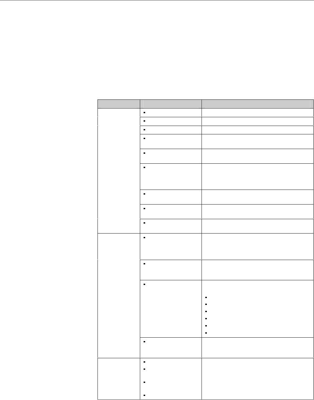
Using the telephone modem, Table 1 shows the information that can be obtained
from the A3 ALPHA meter/collector.
Reading the A3 ALPHA
Meter/Collector
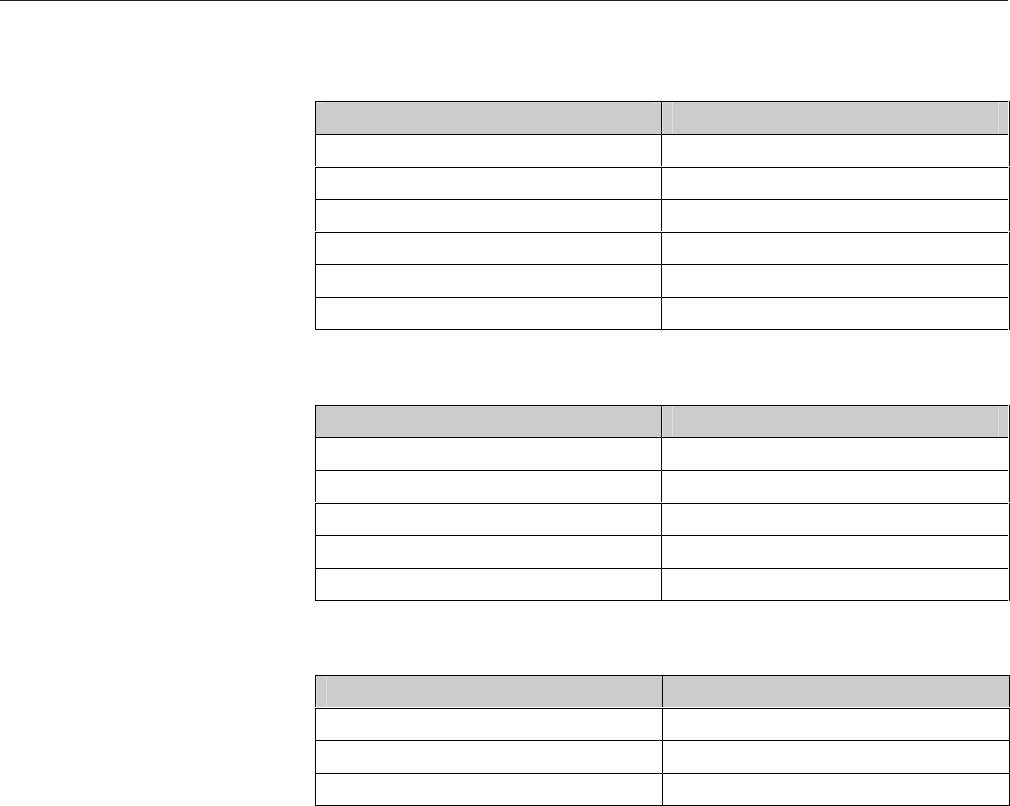
Category Items Indicates
Hardware version Hardware version of the ILC1 option board
LAN ID Complete A3 ALPHA meter/collector LAN ID
Firmware version ILC1 option board firmware version number
Utility ID A utility’s unique ID for all meters within its
network
Firmware S-Spec Manufacturer identifier of the ILC1 option board
firmware
User shared memory The amount of memory used in the ILC1 option
board for storage (including such things as load
profiling records and billing data for each REX
meter)
LAN node types Whether the A3 ALPHA meter is operating as a
node or a collector in the network
Available shared
memory
The amount of storage available on the ILC1
option board
LAN controller
status
Errors A condition that affects the operation of the ILC1
option board
Registered nodes The number of REX meters that are registered to
the A3 ALPHA meter/collector and the unique
identification number (LAN Id) of the registered
nodes.
Repeaters The number of REX meters that are registered to
the A3 ALPHA meter/collector that are operating
as a repeater
LAN status
Event list The date and time of the most recent of the
following events:
REX meter read (start and stop)
REX meter load profiling read (start and stop)
node scan (start and stop)
partial load profiling read (start and stop)
A3 ALPHA meter/collector time broadcast
Clear REX meter registration
Communication
statistics
For each REX meter, the number of read/write
as compared to the number of successful
reads/writes.
Billing data Current billing data
Previous billing period
data
Previous season
billing data
Load profile data
Billing data is available for each REX meter
registered to the data collector. For a list of the
specific data that can be read from a REX meter,
refer to the REX meter technical manual (TM42-
2210A).
Table 1. Information available remotely
For more details about the items available through the ITM3 option board, see the
Elster Electricity meter support software documentation.
A3 ALPHA Meter/Collector PG42-1005A
8July 2003
If the A3 ALPHA meter/collector must be taken out of service (because of an
error condition, the telephone modem fails, etc.), the A3 ALPHA meter/collector
can be replaced with another A3 ALPHA meter/collector.
Since the REX meters within the network register with a meter/collector, a
change out procedure needs to be performed to make certain that the REX
meters will communicate with the new A3 ALPHA meter/collector. Follow these
steps to change out an old meter/collector with a new meter/collector:
1 Before beginning the change out procedure, verify that the new A3 ALPHA
meter/collector is properly configured (see Metercat Program Development
Guide for specific details).
2 Using Metercat software, perform a billing or diagnostic read on the old A3
ALPHA meter/collector. Be certain to include storage mode (either append or
replace) and all of the internal LAN controller data in the read.
3 Make a note of the old A3 ALPHA meter/collector LAN ID obtained from the
billing or diagnostic read performed in step 2.
4 Remove the old A3 ALPHA meter/collector from service. (See A3 ALPHA
Meter Technical Manual for specific details).
5 Install the new A3 ALPHA meter/collector. Be sure to follow the installation
instructions that are provided with the A3 ALPHA meter/collector to correctly
install the meter/collector.
6 Using Metercat software, perform the "Change Out LAN Collector" function.
(See Metercat user Guide for specific details). The old A3 ALPHA meter/
collector LAN ID obtained in step 3 will be needed to complete the change
out function.
After the change out command is performed, the REX meters will re-register with
the new A3 ALPHA meter/collector.
Changing an A3 ALPHA
Meter with ILC1 Option
Board Use authorized utility procedures to remove metering equipment. Dangerous
voltages are present. Equipment damage, personal injury, or death can result if
safety procedures are not followed.
WARNING
!
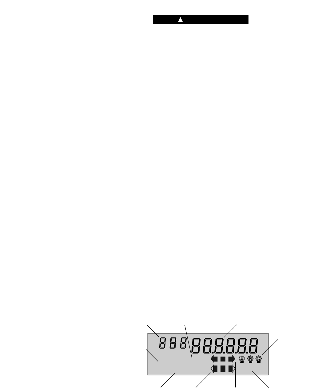
The A3 ALPHA meter display can be divided into different regions as shown in
Figure 3. See Chapter 3, "Operating Instructions," in the A3 ALPHA meter
technical manual (TM42-2190) for more detailed descriptions of the LCD and its
display regions.
Display List Items
ARh
CUM
KW
RATE
TOTAL
RESETS
CONT
MAX
ABCD
PREV SEAS
TEST
ALT EOI
Quantity identifier
Operating mode
indicator Display
quantity
Potential
indicators
End of interval
indicator
Real energy
indicators
Alternate
energy
indicators
Power/energy
units identifier
Display identifiers
Figure 3. A3 ALPHA meter LCD
PG421005A A3 ALPHA Meter/Collector
July 2003 9
The display format for all displayable items, including the items relating to the
ILC1 option board, can be programmed using Elster Electricity meter support
software.
ILC1 Option Board Error Codes
Unlike A3 ALPHA meter error codes, ILC1 option board error codes must be
programmed as displayable items in the A3 ALPHA meter display list; otherwise,
the meter LCD will not display any indication that a condition exists that affects
the ILC1 option board's operation. Table 2 identifies the ILC1 option board error
conditions and the associated display quantity value. The quantity identifier is the
same for all ILC1 option board error codes and can be any numeric character
(represented by i in Table 2).
Condition Quantity identifier Display quantity value
No error iii 000000
Clock error iii 000001
Carryover error iii 000010
Table CRC error iii 000100
Configuration error iii 001000
Shared memory error iii 010000
Power fail data save error iii 100000
Table 2. Error conditions and codes
Error codes may be displayed in combination (for example, iii-100001) indicating
that more than one error condition has been detected.
No error. This code is displayed when no error condition exists in the ILC1 option
board. Since ILC1 option board error codes must be programmed as display
items, the no error code is used when no error condition is present in the ILC1
option board.
Clock error. This code indicates an error with the timekeeping ability of the ILC1
option board. The ILC1 option board can lose its real time clock if the A3 ALPHA
meter has lost its timekeeping capability or if the ILC1 option board cannot
communicate with the A3 ALPHA meter. When this condition is present, all REX
meters in the network revert to relative timekeeping and store all energy data in
the default rate.
Replace the meter battery. The ILC1 option board periodically attempts to read
time from the A3 ALPHA meter (the ILC1 option board reads the time every 15
minutes by default). The ILC1 error will clear after the ILC1 successfully communi-
cates to the A3 ALPHA meter and reads a valid time. The error code should be
cleared within 15 minutes of the time the battery is replaced. If the error code
continues to be displayed, return the A3 ALPHA meter with ILC1 option board to
Elster Electricity for repair or replacement.
Carryover error. This code indicates that the ILC1 option board's battery-backed
RAM was not maintained during a power failure. When there is a power failure,
battery-backed RAM on the ILC1 option board is maintained by the A3 ALPHA
meter's super capacitor or battery. If both of these fail, the data stored in RAM is
lost. The meter battery may need to be replaced. The ILC1 option board error will
be cleared remotely by the MAS.
Table CRC error. This code indicates a possible error in the ILC1 option board's

A3 ALPHA Meter/Collector PG42-1005A
10 July 2003
programming. This error may be corrected remotely by the MAS. If the error code
is displayed after reprogramming, return the A3 ALPHA meter with ILC1 option
board to Elster Electricity for repair or replacement.
General configuration error. This code indicates a problem with the ILC1 option
board's configuration or program. The error may be corrected remotely by the
MAS. Contact Elster Electricity if this error code continues to be displayed on the
LCD.
Shared memory error. This code indicates that one of the following conditions
has occurred:
■The amount of memory requested by the ILC1 program exceeds the amount
of physical memory present.
■The shared memory configuration has been changed and a clear data
command has not been performed.
Shared memory on the ILC1 option board is used to allow the number of regis-
tered meters and the number of meters for which the ILC1 option board stores
profile data to be varied to meet specific applications. The ILC1 option board will
support a maximum of 1024 registered nodes. The amount of memory required
to store current billing data, previous period billing data, and previous season
data limits the amount of data available for storage of load profile data. There are
two variables that control the amount of shared memory required to store load
profile data:
■The number of REX meters for which load profile data is to be stored.
■The number of days of data to store for each REX meter.
As these two load profile variables are increased, the maximum number of
registered nodes must be decreased to allow all of the data to fit within the
available shared memory on the ILC1 option board.
If a shared memory error exists, it can be corrected remotely by the MAS.
Contact Elster Electricity if this error code continues to be displayed on the LCD.
Power fail data save error. This code indicates that the data saved in the ILC1
option board's nonvolatile memory during a power fail may be invalid. This error
will be displayed when power is restored to the meter if a self check has discov-
ered an error with the ILC1 option board's memory. This error can be corrected
remotely by the MAS.
ILC1 Option Board Status Codes
For ILC1 status codes to appear on the A3 ALPHA LCD they must be pro-
grammed as displayable items. Status codes indicate the operational status of
the ILC1 option board. Unlike error codes, the status codes do not indicate a
problem with the ILC1 option board. Table 3 identifies the status condition and its
associated display quantity value. The quantity identifier is represented by i in
Table 3.
Condition Quantity identifier Display quantity value
Collector operation iii 000001
Table 3. Status condition and code

PG421005A A3 ALPHA Meter/Collector
July 2003 11
Collector operation. This code indicates that the A3 ALPHA meter is operating as
a collector. While operating as a collector, the A3 ALPHA meter is collecting and
storing REX meter data.
ILC1 Option Board Information
ILC1 option board information can be displayed on the A3 ALPHA meter LCD.
ILC1 option board information are items that are not associated with any particu-
lar error condition. Table 4 identifies all the items that are available for display. The
quantity identifier must be a numeric character (represented by i in Table 4) and
should be unique for each item that you want to display. Use Elster Electricity
meter support software to select the display items and their associated quantity
identifier.
Display item Quantity identifier Display quantity value
REX LAN ID 2 iii xxxxxx
REX LAN ID 1 iii xxxx
REX utility ID iii xxxxxx
ILC number of nodes iii xxxxxx
ILC number of repeaters iii xxxxxx
Table 4. Information items and display format
REX LAN ID 2. This item displays the last 6 digits of the ILC1 option board LAN
ID.
REX LAN ID 1. This item displays the first 4 digits of the ILC1 option board LAN
ID.
REX utility ID. This item displays the utility ID for the A3 ALPHA meter/collector.
The utility ID is the same for all meters that are part of a network.
ILC number of nodes. This item displays the number of REX meters that are
registered to the A3 ALPHA meter/collector.
ILC number of repeaters. This item displays the number of REX meters that are
registered to the A3 ALPHA meter/collector and that are operating as a repeater.
The ILC1 option board has configuration parameters that determine how much
data can be stored. Table 5 through Table 7 show the estimated number of days
of load profiling intervals available, depending on the following factors:
■length of the REX meter's load profiling interval
■number of REX meters the A3 ALPHA meter/collector has registered
Table 5 through Table 7 assume that the A3 ALPHA meter/collector reads and
stores load profiling data for all registered nodes.
Memory Capacity
A3 ALPHA Meter/Collector PG42-1005A
12 July 2003
REX meters allowed to register Days of LP storage
35 40
70 20
100 14
250 5
500 2
1024 1
Table 5. Maximum number of days of load profiling storage available based on
15-minute load profiling intervals
REX meters allowed to register Days of LP storage
70 40
100 28
250 11
500 5
1024 2
Table 6. Maximum number of days of load profiling storage available based on
30-minute load profiling data intervals
REX meters allowed to register Days of LP storage
140 40
250 22
500 11
Table 7. Maximum number of days of load profiling storage available based on
60-minute load profiling data intervals

PG421005A A3 ALPHA Meter/Collector
July 2003 13
Compliance Statement (Part 15.19)
The A3 ALPHA meter/collector complies with Part 15 of the FCC Rules and with
RSS-210 of Industry Canada. Operation is subject to the following two condi-
tions: 1) This device may not cause harmful interference, and 2) This device must
accept any interference received, including interference that may cause undesired
operation.
Warning (Part 15.21)
Changes or modifications not expressly approved by Elster Electricity, LLC could
void the user's authority to operate the equipment.
RF Radiation Safety Guidelines per Part 2 of FCC Rules
and Regulations
The meter should be installed in a location where there will be a separation
greater than 20 cm from locations occupied by humans.
User Information (Part 15.105)
The A3 ALPHA meter/collector has been tested and found to comply with the
limits for a Class B digital device, pursuant to part 15 of the FCC Rules. These
limits are designed to provide reasonable protection against harmful interference
in a residential installation. This equipment generates, uses and can radiate radio
frequency energy and, if not installed and used in accordance with the instruc-
tions, may cause harmful interference to radio communications. However, there is
no guarantee that interference will not occur in a particular installation. If this
equipment does cause harmful interference to radio or television reception, the
user is encouraged to try to correct the interference by one or more of the
following measures:
■Reorient or relocate the receiving antenna.
■Move the receiving equipment farther away from the A3 ALPHA meter/
collector.
■Consult the dealer or an experienced radio/TV technician for help.
Industry Canada Statement
The term "IC" before the certification/registration number only signifies that the
Industry Canada technical specifications were met.
FCC and Industry
Canada Compliance

A3 ALPHA Meter/Collector PG42-1005A
14 July 2003
Absolute Maximums
Voltage Continuous 528 VAC
Surge voltage withstand Test performed Results
ANSI C37.90.1 Oscillatory 2.5 kV, 2500 strikes
Fast Transient 5 kV, 2500 strikes
ANSI C62.41 6 kV @ 1.2/50 µs, 10 strikes
IEC 61000-4-4 4 kV, 2.5 kHz repetitive burst for 1 minute
ANSI C12.1 Insulation 2.5 kV, 60Hz for 1 minute
Current Continuous at Class Amperes
Temporary (1 second) at 200 % of meter maximum current
Operating Ranges
Voltage Nameplate nominal range Operating range
120 V to 480 V (May have to be form dependent due to emissions
issues. We should know the answer to this early next week)
96 V to 528 V
Current 0 to Class amperes
Frequency Nominal 50 Hz or 60 Hz ± 5 %
Temperature range -40 °C to +85 °C inside meter cover
Humidity range 0 % to 100 % noncondensing
Operating Characteristics
Power supply burden (Phase A) Less than 4 W
Per phase current burden 0.1 milliohms typical at 25 °C
Per phase voltage burden 0.008 W @ 120 V 0.03 W @ 240 V 0.04 W @ 480 V
Accuracy Meets ANSI 12.20 accuracy for accuracy class 0.2 %
General Performance Characteristics
Starting current
Form 1S and Form 3S 10 mA for Class 20 100 mA for Class 200 160 mA for Class 320
All other forms 5 mA for Class 20 50 mA for Class 200 80 mA for Class 320
Startup delay Less than 3 seconds from power application to pulse accumulation
Creep 0.000 A (no current) No more than one pulse measured per quantity, conforming to ANSI C12.1 requirements
Primary time base Power line frequency (50 Hz or 60Hz), with selectable crystal oscillator
Secondary time base Meets the ANSI limit of 0.02 % using the 32.768 kHz crystal. Initial performance is expected to be equal to or better than ± 55 seconds per
month at room temperature
Outage carryover capacity 6 hours at 25 °C. Supercapacitor rated at 0.1 Farads, 5.5 V
Battery (optional) LiSOCl
2
battery rated 800 mAhr, 3.6 V and shelf life of 20+ years. Five years continuous duty at 25 °C
Communications rate Optical port 9600 baud (nominal)
ITM3 option board 1200 bps or 2400 bps
ILC1 900 MHz radio 17600 bps
Applicable Standards
ANSI C12.1 C12.10 C12.20 C12.18 C12.19 C12.21
Technical
Specifications

PG421005A A3 ALPHA Meter/Collector
July 2003 15
DISCLAIMER OF WARRANTIES AND LIMITATIONS OF LIABILITY
There are no understandings, agreements, representations, or warranties either express or implied, including warranties of merchantability or
fitness for a particular purpose, other than those specifically set out by any existing contract between the parties. Any such contract states
the entire obligation of the seller. The contents of this document shall not become part of or modify any prior existing agreement,
commitment, or relationship.
The information, recommendations, descriptions, and safety notices in this document are based on Elster Electricity, LLC experience and
judgment with respect to operation and maintenance of the described product. This information should not be considered as all-inclusive or
covering all contingencies. If further information is required, Elster Electricity, LLC should be consulted.
No warranties, either expressed or implied, including warranties of fitness for a particular purpose or merchantability, or warranties arising
from the course of dealing or usage of trade, are made regarding the information, recommendations, descriptions, warnings, and cautions
contained herein.
In no event will Elster Electricity, LLC be responsible to the user in contract, in tort (including negligence), strict liability or otherwise for any
special, indirect, incidental, or consequential damage or loss whatsoever, including but not limited to: damage or loss of use of equipment,
cost of capital, loss of profits or revenues, or claims against the user by its customers resulting from the use of the information,
recommendations, descriptions, and safety notices contained herein.

Elster Electricity, LLC
Raleigh, North Carolina, USA
+1 800 338 5251 (US toll free)
+1 919 212 4800
support@us.elster.com
www.elsterelectricity.com
Information herein is subject to change without notice. Product
specifications cited are those in effect at the time of publication.
© 2003 by Elster Electricity, LLC. All rights reserved.
Printed in the United States.