Elster Solutions REXILCA LAN Option Board User Manual A3 ALPHA Meter Collector Product Guide
Elster Solutions, LLC LAN Option Board A3 ALPHA Meter Collector Product Guide
Contents
- 1. Users Manual I
- 2. Users Manual II
Users Manual II

A3 ALPHA® Meter/Collector
Product Guide
PG42-1005B

© 2004 by Elster Electricity, LLC. All rights are reserved.
No part of this software or documentation may be reproduced, transmitted, processed or recorded by any means or
form, electronic, mechanical, photographic or otherwise, translated to another language, or be released to any third
party without the express written consent of Elster Electricity, LLC.
Printed in the United States of America.
ALPHA, ALPHA Plus, and EnergyAxis are registered trademarks; and Metercat, AlphaPlus, and REX are trademarks of
Elster Electricity, LLC.
Other product and company names mentioned herein may be the trademarks and/or registered trademarks of their
respective owners.
DISCLAIMER OF WARRANTIES AND LIMITATIONS OF LIABILITY
There are no understandings, agreements, representations, or warranties either expressed or implied, including warranties of
merchantability or fitness for a particular purpose, other than those specifically set out by any existing contract between the par-
ties. Any such contract states the entire obligation of the seller. The contents of this document shall not become part of or mod-
ify any prior existing agreement, commitment, or relationship.
The information, recommendations, descriptions, and safety notices in this document are based on Elster Electricity, LLC expe-
rience and judgment with respect to operation and maintenance of the described product. This information should not be con-
sidered as all-inclusive or covering all contingencies. If further information is required, Elster Electricity, LLC should be consulted.
No warranties, either expressed or implied, including warranties of fitness for a particular purpose or merchantability, or warran-
ties arising from the course of dealing or usage of trade, are made regarding the information, recommendations, descriptions,
warnings, and cautions contained herein.
In no event will Elster Electricity, LLC be responsible to the user in contract, in tort (including negligence), strict liability or other-
wise for any special, indirect, incidental, or consequential damage or loss whatsoever, including but not limited to: damage or
loss of use of equipment, cost of capital, loss of profits or revenues, or claims against the user by its customers resulting from
the use of the information, recommendations, descriptions, and safety notices contained herein.
A3 ALPHA Meter/Collector
July 2004 Product Guide
i
Contents General Description . . . . . . . . . . . . . . . . . . . . . . . . . . . . . . . . . . . . 1
A3 ALPHA Meter Circuit Board . . . . . . . . . . . . . . . . . . . . . . . . . . . . 1
Metercat Programming Note . . . . . . . . . . . . . . . . . . . . . . . . . . . . . . . . . . . . . . . . . . . .3
Metering Software and System . . . . . . . . . . . . . . . . . . . . . . . . . . . . 3
Metercat . . . . . . . . . . . . . . . . . . . . . . . . . . . . . . . . . . . . . . . . . . . . . . . . . . . . . . . . . . . .3
EnergyAxis Metering Automation Server. . . . . . . . . . . . . . . . . . . . . . . . . . . . . . . . . . .3
Operation of the A3 ALPHA Meter with ILC1 Option Board . . . . . . 4
Billing Date . . . . . . . . . . . . . . . . . . . . . . . . . . . . . . . . . . . . . . . . . . . . . . . . . . . . . . . . . .4
TOU Schedules . . . . . . . . . . . . . . . . . . . . . . . . . . . . . . . . . . . . . . . . . . . . . . . . . . . . . . .4
Calendar . . . . . . . . . . . . . . . . . . . . . . . . . . . . . . . . . . . . . . . . . . . . . . . . . . . . .5
Season Changes . . . . . . . . . . . . . . . . . . . . . . . . . . . . . . . . . . . . . . . . . . . . . . . . . . . . . .5
Call Initiation . . . . . . . . . . . . . . . . . . . . . . . . . . . . . . . . . . . . . . . . . . . . . . . . . . . . . . . . .5
Power Failure . . . . . . . . . . . . . . . . . . . . . . . . . . . . . . . . . . . . . . . . . . . . . . . . . . . . . . . .6
Loss of Real Time . . . . . . . . . . . . . . . . . . . . . . . . . . . . . . . . . . . . . . . . . . . . . . . . . . . . .6
Reading the A3 ALPHA Meter/Collector . . . . . . . . . . . . . . . . . . . . . 6
Changing an A3 ALPHA Meter with ILC1 Option Board . . . . . . . . . 7
Display List Items . . . . . . . . . . . . . . . . . . . . . . . . . . . . . . . . . . . . . . 7
ILC1 Option Board Error Codes . . . . . . . . . . . . . . . . . . . . . . . . . . . . . . . . . . . . . . . . . .8
No error . . . . . . . . . . . . . . . . . . . . . . . . . . . . . . . . . . . . . . . . . . . . . . . . . . . . .8
Clock error . . . . . . . . . . . . . . . . . . . . . . . . . . . . . . . . . . . . . . . . . . . . . . . . . . .8
Carryover error . . . . . . . . . . . . . . . . . . . . . . . . . . . . . . . . . . . . . . . . . . . . . . . .9
Table CRC error . . . . . . . . . . . . . . . . . . . . . . . . . . . . . . . . . . . . . . . . . . . . . . .9
General configuration error . . . . . . . . . . . . . . . . . . . . . . . . . . . . . . . . . . . . . . .9
Shared memory error . . . . . . . . . . . . . . . . . . . . . . . . . . . . . . . . . . . . . . . . . . .9
Power fail data save error . . . . . . . . . . . . . . . . . . . . . . . . . . . . . . . . . . . . . . . .9
ILC1 Option Board Status Codes. . . . . . . . . . . . . . . . . . . . . . . . . . . . . . . . . . . . . . . . .9
Collector operation . . . . . . . . . . . . . . . . . . . . . . . . . . . . . . . . . . . . . . . . . . . . .9
ILC1 Option Board Information . . . . . . . . . . . . . . . . . . . . . . . . . . . . . . . . . . . . . . . . .10
REX LAN ID 1 . . . . . . . . . . . . . . . . . . . . . . . . . . . . . . . . . . . . . . . . . . . . . . . .10
REX LAN ID 2 . . . . . . . . . . . . . . . . . . . . . . . . . . . . . . . . . . . . . . . . . . . . . . . .10
REX utility ID . . . . . . . . . . . . . . . . . . . . . . . . . . . . . . . . . . . . . . . . . . . . . . . . .10
ILC number of nodes . . . . . . . . . . . . . . . . . . . . . . . . . . . . . . . . . . . . . . . . . .10
ILC number of repeaters . . . . . . . . . . . . . . . . . . . . . . . . . . . . . . . . . . . . . . . .10
Memory Capacity . . . . . . . . . . . . . . . . . . . . . . . . . . . . . . . . . . . . . 10
FCC and Industry Canada Compliance . . . . . . . . . . . . . . . . . . . . . 11
Compliance Statement (Part 15.19) . . . . . . . . . . . . . . . . . . . . . . . . . . . . . . . . . . . . . .11
Warning (Part 15.21) . . . . . . . . . . . . . . . . . . . . . . . . . . . . . . . . . . . . . . . . . . . . . . . . . .11
RF Radiation Safety Guidelines per Part 2 of FCC Rules and Regulations . . . . . . .11
User Information (Part 15.105) . . . . . . . . . . . . . . . . . . . . . . . . . . . . . . . . . . . . . . . . . .11
Industry Canada Statement . . . . . . . . . . . . . . . . . . . . . . . . . . . . . . . . . . . . . . . . . . . .12
Technical Specifications . . . . . . . . . . . . . . . . . . . . . . . . . . . . . . . . 12
Operating Ranges . . . . . . . . . . . . . . . . . . . . . . . . . . . . . . . . . . . . . . . . . . . . . . . . . . . .12
Product
Guide
A3
ALPHA
Meter/Collector
A3 ALPHA Meter/Collector
Product Guide July 2004
ii
A3 ALPHA Meter/Collector
July 2004 Product Guide
1
General Description The A3 ALPHA meter/collector is the component of the EnergyAxis®System
that provides the interface between the Metering Automation Server (MAS) and
the local network of REX™ meters that are registered to the meter/collector. MAS
communicates with the A3 ALPHA meter/collector using a standard telephone
line. The A3 ALPHA meter/collector then communicates with its registered REX
meters using a 2-way 900 MHz radio frequency network. The primary task of
the internal LAN controller (ILC1) option board is to maintain the local area net-
work (LAN) and read and store billing data from REX meters. The A3 ALPHA
meter/collector is responsible for various activities within the network of REX
meters, including the following:
■reading and storing the billing data from each REX meter on a periodic
basis
■reading and storing the load profiling data from a configurable number
of REX meters on a periodic basis
■notifying the REX meters to perform demand resets based on a sched-
ule from MAS
■reading and storing the previous billing period data from REX meters
after a demand reset has occurred
■notifying the REX meters to perform season changes based on a
schedule from MAS
■reading and storing the previous season data from REX meters after
season changes have occurred
■synchronizing the REX meters to the system time and TOU day type
■distributing TOU rate schedules and associated display lists to the REX
meters
■reading or sending commands to an individual REX meter on request
from MAS
■performing other network maintenance tasks
■reporting the billing and load profiling data back to MAS
A3 ALPHA Meter Circuit
Board
The A3 ALPHA meter builds upon the strengths of the existing ALPHA meter
designs. Like its predecessors, the A3 ALPHA meter uses Elster Electricity's
patented digital measurement techniques that offer high accuracy, repeatability,
and low ownership costs. In support of open architecture standards, the
A3 ALPHA meter is the first Elster Electricity meter to fully support ANSI C12.18,
C12.19, and C12.21 standards.
To function as a collector, an A3 ALPHA meter requires the following two option
boards:
■internal telephone modem (ITM3) with optional outage reporting capa-
bilities
■internal LAN controller (ILC1)
The ITM3 option board connects to the A3 ALPHA meter using the 20-pin
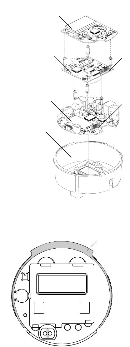
header (J4) on the meter circuit board as shown in Figure 1. The ILC1 option
board connects to the ITM3 option board using the 20-pin header (J5) as shown
in Figure 1.
The antenna for the ILC1 option board mounts directly onto the electronic hous-
ing (see Figure 2) and fits completely under the cover of the A3 ALPHA meter.
Product
Guide
A3 ALPHA
Meter/Collector
A3 ALPHA Meter/Collector
Product Guide July 2004
2
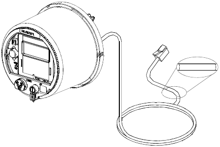
An A3 ALPHA meter/collector has a 4-conductor telephone cable exiting the
meter with an RJ-11 connector at the end as shown in Figure 3. There is a wire
marker approximately 6 inches from the RJ-11 end with “INT MOD ITM3”
printed on it for identifying that the ITM3 option board is installed.
Figure 1. A3 ALPHA meter electronic assembly
Figure 2. A3 ALPHA electronic housing with antenna
Meter electronic
housing
J4
J5
ILC1 option
board
ITM3 option
board
Meter circuit
board
Antenna
A3 ALPHA Meter/Collector
July 2004 Product Guide
3
Figure 3. A3 ALPHA meter with ITM3 RJ-11 cable
Metercat Programming Note
To have the A3 ALPHA meter function properly as a data collector in the
EnergyAxis System, it is important that the meter be programmed correctly
using Metercat™. In the Remote component tab in Metercat, be sure that the fol-
lowing options are set:
■Port 1 usage is set to internal modem.
■Port 2 usage is set to direct connect.
■On the Port 1 Modem tab, enable line sharing (the Enable Line Sharing
box is checked).
■On the Port 2 Direct Connect tab, the bit rate is set to 9600.
The other options can be set as desired. For more information on using Meter-
cat, see the Metercat documentation.
Metering Software and
System
Metercat
The A3 ALPHA meter/collector requires Elster Electricity Metercat support soft-
ware release 1.4 or later. Metercat offers the following features:
■program development to create user-defined configuration data
■meter programming to send user-defined configuration data or com-
mands to the meter
■meter reading to receive data that has been stored by the meter
■diagnostic read including ILC1 option board and LAN status
■ability to perform tasks related to replacing a collector
EnergyAxis Metering Automation Server
The EnergyAxis Metering Automation Server (MAS) reads meters over telephone
or wireless networks. Using MAS, meter readings can be scheduled or per-
formed on-request from the browser-based user interface. MAS allows all billing
data to be read from the meter; this includes data from the A3 ALPHA meter
and from each REX meter registered with the ILC1 option board. Billing data
from the A3 ALPHA meter includes multi-channel interval data, consumption,
demand, time-of-use registers as well as meter status flags. REX meter data can
be read from the stored data in the collector or on-request by using MAS to
communicate through the collector to the individual REX meter.
INT MOD ITM3
A3 ALPHA Meter/Collector
Product Guide July 2004
4
Data exchange with MAS is performed using an open XML schema, AMR Data
Exchange Format (AMRDEF), so that interfaces with billing systems and other
enterprise systems can be easily implemented. MAS also comes with the
JSlinger module, a powerful driver for file transfer protocol (FTP) that can trans-
form, compress and encrypt data files prior to sending them to trusted IP
addresses across the Internet.
Operation of the
A3 ALPHA Meter with
ILC1 Option Board
The A3 ALPHA meter and the ILC1 option board typically operate independently
of each other. The primary task of the ILC1 option board is to maintain the LAN
and read and store billing data from REX meters. The ILC1 option board com-
municates with the A3 ALPHA meter to read time and day type information. This
information is then propagated through the LAN to the REX meters. The time
base in the A3 ALPHA meter is used as the system time for the LAN, and the
ILC1 option board periodically reads this time and distributes the time to the
LAN.
Billing Date
The ILC1 option board handles the billing dates for the REX meters it has regis-
tered. Configuration options in the ILC1 option board permit each REX meter to
be assigned to one of thirty billing date cycles. The ILC1 option board makes
certain that the REX meters perform demand resets on the correct dates using
the billing date cycles.
The REX meter stores a copy of the billing data before the demand is reset. This
billing data copy can then be read and stored by the ILC1 option board. REX
meter billing dates can be controlled by MAS.
For A3 ALPHA meters, the billing date (or, the demand reset date) can be con-
trolled by either of the following:
■by the calendar programmed into the A3 ALPHA meter using Metercat
support software
■by MAS when MAS calls the A3 ALPHA meter on the billing date and
issues a demand reset command
TOU Schedules
The ILC1 option board stores up to 8 separate meter programs. Each program
can support a TOU schedule and has its own associated display list. MAS
assigns each registered REX meter to one of the programs and associated dis-
play list.
Each TOU schedule for the REX meter consists of weekday, weekend, and two
special day types (that is, holidays). The ILC1 option board broadcasts the TOU
schedule to the REX meters where the schedules are stored and used to record
kWh data in the correct TOU register. The ILC1 option board reads and stores
TOU data from each REX meter as part of the normal billing read.
The display list controls the values that are shown on the REX meter LCD. See
Appendix B, “Display,” of the REX Meter Technical Manual (TM42-2210) for
information on the values that can be displayed on the REX meter LCD.
Using MAS Release 5.0 and later, users can remotely change the TOU sched-
ules and associated display lists stored in the ILC1 option board. The ILC1
option board verifies the delivery of the TOU schedule and associated display list
to each REX meter.
A3 ALPHA Meter/Collector
July 2004 Product Guide
5
The A3 ALPHA meter uses its own, separate TOU switch points (programmed
into the A3 ALPHA meter using Metercat support software) that are independent
from the ILC1 option board switch points.
Calendar. The ILC1 option board reads the A3 ALPHA meter calendar to
determine the day type for the next 32 days and relays this to the REX meters
registered to the collector.
Season Changes
Season changes for the A3 ALPHA meter/collector are controlled by the calen-
dar in the A3 ALPHA meter. Season changes for the REX meters are controlled
by calendars in the ILC1 option board. The ILC1 option board has season
change dates for each of eight possible TOU schedules. Using the season
change information, the ILC1 option board makes certain that the associated
REX meter performs a season change on the correct date. After a season
change, the ILC1 option board will read and store a season change copy of the
billing data from associated REX meters.
Call Initiation
The A3 ALPHA meter/collector can initiate billing, alarm, and outage/restoration
calls based on the customer program configured in the meter (see Metercat
documentation or the ITM3 product guide PG42-1006 for more information on
call initiation). Additionally, the ILC1 option board can independently initiate
alarm calls to report the following conditions:
■an additional REX meter has been registered to this collector
■a REX meter's demand threshold has been exceeded (the REX meter
itself must also be enabled to report this condition to the collector)
■power has been restored to a REX meter (the REX meter itself must also
be enabled to report this condition to the collector)
■warning conditions related to REX meters with an internal service dis-
connect switch (the REX meter itself must also be enabled to report this
condition to the collector)
For each of these exceptions, the ILC1 option board can be configured to ini-
tiate a call at the following times:
■never
■immediately
■after a configurable delay of 1 to 255 minutes
■daily
Telephone calls initiated by the ILC1 option board use the A3 ALPHA meter's
settings for alarm calls.
A3 ALPHA Meter/Collector
Product Guide July 2004
6
Power Failure
When there is a power failure, the A3 ALPHA meter initiates a shutdown and
stores the A3 ALPHA meter billing data and status information in EEPROM. All
billing data information stored in the ILC1 option board is stored in battery-
backed RAM. The A3 ALPHA meter's real-time clock and the data stored in the
ILC1 option board are maintained by the super capacitor and battery during a
power failure.
If both the super capacitor and battery fail, all RAM in the meter and in the ILC1
will be lost. Upon subsequent power restoration, an error code is generated for
both the A3 ALPHA meter and the ILC1 option board.
■For information on A3 ALPHA meter error codes, see the A3 ALPHA
Meter Technical Manual (TM42-2190).
■For information on ILC1 option board error codes, see “ILC1 Option
Board Error Codes” on page 8.
Loss of Real Time
Within the network, the REX meters obtain real time from time signals sent by
the collector. The ILC1 option board does not have its own real time clock;
instead, it obtains the time directly from the A3 ALPHA meter. There are two
ways the ILC1 option board can lose time from the A3 ALPHA meter:
■A3 ALPHA meter has lost its timekeeping capability
■the ILC1 option board cannot communicate with the A3 ALPHA meter
If the ILC1 option board loses time, the REX meters in the network will continue
to keep real time and date for up to 32 days or until the REX meter has a power
outage. The REX meters will then revert to relative timekeeping and store all
TOU energy data in the default rate.
The A3 ALPHA meter LCD will indicate the ILC1 option board’s loss of real time
by displaying an error code (see “ILC1 Option Board Error Codes” on page 8 for
more information).
Reading the A3 ALPHA
Meter/Collector
The A3 ALPHA meter/collector can be read in the following ways:
■visually using the LCD
■optically or remotely using Metercat support software
■remotely via the ITM3 option board using MAS
For more details on the information that can be viewed on the LCD, see “Display
List Items” on page 7.
For more details on reading the A3 ALPHA meter/collector optically, see the
Metercat documentation and online Help.
For more details on reading the A3 ALPHA meter/collector remotely, see the
MAS documentation and online Help.

A3 ALPHA Meter/Collector
July 2004 Product Guide
7
Changing an A3 ALPHA
Meter with ILC1 Option
Board
Use authorized utility procedures to remove metering equipment. Dangerous
voltages are present. Equipment damage, personal injury, or death can result if
safety procedures are not followed.
If the A3 ALPHA meter/collector must be taken out of service (because of an
error condition, the telephone modem fails, etc.), the A3 ALPHA meter/collector
can be replaced with another A3 ALPHA meter/collector.
Since the REX meters within the network register with a collector, a change out
procedure needs to be performed to make certain that the REX meters will com-
municate with the new A3 ALPHA meter/collector. Follow these steps to change
out an old meter/collector with a new meter/collector:
1. Before beginning the change out procedure, verify that the new
A3 ALPHA meter/collector is properly configured. See Metercat Pro-
gram Development Guide (TM42-2204) for specific details.
2. Using Metercat software, perform a billing or diagnostic read on the old
A3 ALPHA meter/collector. Be certain that Metercat is configured to
perform the following:
■store the reading
■read all of the internal LAN controller data
3. Make a note of the old A3 ALPHA meter/collector LAN ID obtained from
the billing or diagnostic read performed in step 2. The LAN ID is found
on the Internal LAN Controller tab of the Status view.
Note. The LAN ID is also available on the nameplate. See Appendix C,
“Nameplate Information,” in the REX Meter Technical Manual
(TM42-2210) for more details.
4. Remove the old A3 ALPHA meter/collector from service. See
A3 ALPHA Meter Technical Manual (TM42-2190) for specific details.
5. Install the new A3 ALPHA meter/collector. Be sure to follow the instruc-
tions that are provided with the A3 ALPHA meter/collector to correctly
install the meter/collector.
6. Using Metercat software, perform the “Change Out LAN Collector”
task. See Metercat User Guide (TM42-2204) for specific details. The old
A3 ALPHA meter/collector LAN ID obtained in step 3 will be needed to
complete the change out function.
After the change out command is performed, the REX meters previously regis-
tered with the old meter/collector will re-register with the new A3 ALPHA meter/
collector.
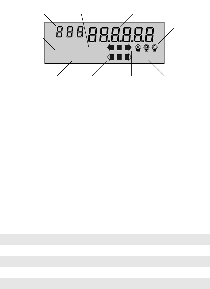
Display List Items The A3 ALPHA meter display is divided into different regions as shown in
Figure 4. See Chapter 3, “Operating Instructions,” in the A3 ALPHA Meter Tech-
nical Manual (TM42-2190) for more detailed descriptions of the LCD and its dis-
play regions.
A3 ALPHA Meter/Collector
Product Guide July 2004
8
Figure 4. A3 ALPHA meter LCD
The display list for all displayable items, including the items relating to the ILC1
option board, can be programmed using Metercat meter support software.
ILC1 Option Board Error Codes
Unlike A3 ALPHA meter error codes, ILC1 option board error codes must be
programmed as a displayable item in the A3 ALPHA meter display list using
Metercat support software; otherwise, the meter LCD will not display any indica-
tion that a condition exists that affects the ILC1 option board’s operation.
Tab l e 1 identifies the ILC1 option board error conditions and the associated dis-
play quantity value. The quantity identifier is the same for all ILC1 option board
error codes and can be programmed to be any numeric character (represented
by i in Table 1).
Table 1. Error conditions and codes
Error codes may be displayed in combination (for example, iii 100001), indicat-
ing that more than one error condition has been detected.
No error. This code is displayed when no error condition exists in the ILC1
option board. Since ILC1 option board error codes must be programmed as dis-
play items, the no error code is used when no error condition is present in the
ILC1 option board.
Clock error. This code indicates an error with the timekeeping ability of the
ILC1 option board. The ILC1 option board can lose its real time clock if the
A3 ALPHA meter has lost its timekeeping capability or if the ILC1 option board
cannot communicate with the A3 ALPHA meter. When this condition is present,
ARh
CUM
KW
RATE
TOTAL
RESETS
CONT
MAX
ABCD
PREV SEAS
TEST
ALT EOI
Quantity identifier
Operating mode
indicator Display
quantity
Potential
indicators
End of interval
indicator
Real energy
indicators
Alternate
energy
indicators
Power/energy
units identifier
Display identifiers
Condition Quantity identifier Display quantity value
No error iii 000000
Clock error iii 000001
Carryover error iii 000010
Table CRC error iii 000100
Configuration error iii 001000
Shared memory error iii 010000
Power fail data save error iii 100000

A3 ALPHA Meter/Collector
July 2004 Product Guide
9
the ILC1 option board ceases LAN communications (modem communication,
however, is still possible) and sets an ILC1 option board clock error.
Replace the meter battery. Using Metercat support software, reprogram the
A3 ALPHA meter/collector. The ILC1 option board clock error will clear within 15
minutes. Once the ILC1 option board clock error clears, the ILC1 will resume
LAN communications. Contact Elster Electricity if this error code continues to
display on the LCD.
Carryover error. This code indicates that the ILC1 option board’s battery-
backed RAM was not maintained during a power failure. When there is a power
failure, battery-backed RAM on the ILC1 option board is maintained by the
A3 ALPHA meter’s super capacitor or battery. If both of these fail, the data
stored in RAM is lost. Upon a subsequent power restoration, the ILC1 option
board will rebuild the current billing data for all REX meters in the network. All
previous billing data will be lost.
Replace the meter battery. Using Metercat support software, reprogram the A3
ALPHA meter/collector. The ILC1 option board clock error will clear within 15
minutes. Once the ILC1 option board clock error clears, the ILC1 will resume
LAN communications. Contact Elster Electricity if this error code continues to
display on the LCD.
Table CRC error. This code indicates an error in the ILC1 option board’s pro-
gramming. Contact Elster Electricity if this error code is displayed on the LCD.
General configuration error. This code indicates a problem with the ILC1
option board’s configuration or program. Contact Elster Electricity if this error
code is displayed on the LCD.
Shared memory error. This code indicates a problem exists in the shared
memory area. See “Memory Capacity” on page 10 for more information on
shared memory. Contact Elster Electricity if this error code is displayed on the
LCD.
Power fail data save error. This code indicates that the data saved in the
ILC1 option board’s nonvolatile memory during a power failure may be invalid.
This error will be displayed when power is restored to the meter if a self check
has discovered an error with the ILC1 option board's memory. Contact Elster
Electricity if this error code continues to be displayed on the LCD.
ILC1 Option Board Status Codes
ILC1 status code must be programmed as a displayable item to appear on the
A3 ALPHA meter LCD using Metercat support software. The status code indi-
cates the presence of an ILC1 option board and that it is performing the collec-
tor function. Unlike error codes, the status codes do not indicate a problem with
the ILC1 option board. Table 2 identifies the status condition and its associated
display quantity value. The quantity identifier is the same for all ILC1 option
board status codes and can be programmed to be any numeric character (rep-
resented by i in Table 2).
Table 2. Status condition and code
Collector operation. This code indicates that the A3 ALPHA meter is operat-
ing as a collector. While operating as a collector, the A3 ALPHA meter is collect-
ing and storing REX meter data using the ILC1 option board.
Condition Quantity identifier Display quantity value
Collector operation iii 000001

A3 ALPHA Meter/Collector
Product Guide July 2004
10
ILC1 Option Board Information
ILC1 option board information can be displayed on the A3 ALPHA meter LCD.
Tab l e 3 identifies all the items that are available for display. The quantity identifier
must be a numeric character (represented by i in Table 3) and should be unique
for each item that you want to display. Use Metercat meter support software to
select the display items and their associated quantity identifier.
Table 3. Information item and display format
REX LAN ID 1. This item displays the first 4 digits of the ILC1 option board
LAN ID.
REX LAN ID 2. This item displays the last 6 digits of the ILC1 option board
LAN ID.
REX utility ID. This item displays the utility ID for the A3 ALPHA meter/collec-
tor. The utility ID is the same for all meters that are part of the same network.
ILC number of nodes. This item displays the number of REX meters that are
registered to the collector.
ILC number of repeaters. This item displays the number of REX meters that
are registered to the collector and that are operating as a repeater.
Memory Capacity The ILC1 option board will support a maximum of 1024 registered nodes. The
amount of memory required to store current billing data, previous period billing
data, previous season data, and configuration change data limits the amount of
data available for storage of load profile data. There are two variables that con-
trol the amount of shared memory required to store load profile data:
■The number of REX meters for which load profile data is to be stored.
■The number of days of data to store for each REX meter.
As these two load profile variables are increased, the maximum number of regis-
tered nodes must be decreased to allow all of the data to fit within the available
shared memory on the ILC1 option board.
Tab l e 4 shows the estimated maximum number of days of load profiling data
that can be stored for various configurations. Table 4 assumes the A3 ALPHA
meter/collector does the following:
■reads load profiling data from each registered REX meter based on the
following schedule:
■for 15-minute intervals, the collection time is every 4 hours
■for 30-minute intervals, the collection time is every 6 hours
■for 60-minute intervals, the collection time is every 12 hours
■reads and stores load profiling data for all registered nodes
The ILC1 option board memory configuration is set at the factory and cannot be
changed.
Display item Quantity identifier Display quantity value
REX LAN ID 1 iii xxxx
REX LAN ID 2 iii xxxxxx
REX utility ID iii xxxxxx
ILC number of nodes iii xxxxxx
ILC number of repeaters iii xxxxxx

A3 ALPHA Meter/Collector
July 2004 Product Guide
11
Table 4. Max. number of days of storage available per interval
FCC and Industry
Canada Compliance
Compliance Statement (Part 15.19)
The A3 ALPHA meter/collector complies with Part 15 of the FCC Rules and with
RSS-210 of Industry Canada. Operation is subject to the following two condi-
tions:
1. This device may not cause harmful interference, and
2. This device must accept any interference received, including interfer-
ence that may cause undesired operation.
Warning (Part 15.21)
Changes or modifications not expressly approved by Elster Electricity, LLC could
void the user’s authority to operate the equipment.
RF Radiation Safety Guidelines per Part 2 of FCC Rules
and Regulations
The meter should be installed in a location where there will be a separation
greater than 20 cm (8 inches) from locations occupied by humans.
User Information (Part 15.105)
The A3 ALPHA meter/collector has been tested and found to comply with the
limits for a Class B digital device, pursuant to part 15 of the FCC Rules. These
REX meters allowed to register Days of LP storage
Load profiling interval: 15 minutes Collection time: every 4 hours
35 54
70 27
100 18
250 7
500 3
1024 1
Load profiling interval: 30 minutes Collection time: every 6 hours
70 50
100 35
250 13
500 5
1024 1
Load profiling interval: 60 minutes Collection time: every 12 hours
70 101
140 49
250 26
500 11
1024 3

A3 ALPHA Meter/Collector
Product Guide July 2004
12
limits are designed to provide reasonable protection against harmful interference
in a residential installation. This equipment generates, uses and can radiate
radio frequency energy and, if not installed and used in accordance with the
instructions, may cause harmful interference to radio communications. However,
there is no guarantee that interference will not occur in a particular installation. If
this equipment does cause harmful interference to radio or television reception,
the user is encouraged to try to correct the interference by one or more of the
following measures:
■Reorient or relocate the receiving antenna.
■Move the receiving equipment farther away from the A3 ALPHA meter/
collector.
■Consult the dealer or an experienced radio/TV technician for help.
Industry Canada Statement
The term “IC” before the certification/registration number only signifies that the
Industry Canada technical specifications were met.
Technical
Specifications
Appendix E, “Technical Specifications,” of the A3 ALPHA Meter Technical Man-
ual (TM42-2190) lists the meter specifications for an A3 ALPHA meter. When the
A3 ALPHA meter is operating as a collector, the operating range for a Form 35S
meter is different than the specifications listed in TM42-2190.
Operating Ranges
Chapter 1, “Internal Telephone Modem,” of the Elster Electricity Modems prod-
uct guide (PG42-1006B or later) lists the specifications for the ITM3 option
board.
Voltage Nameplate nominal range Operating range
Form 35S 120 V to 240 V 96 V to 288 V
All other forms 120 V to 480 V 96 V to 528 V
This page is intentionally left blank.

Elster Electricity, LLC
Raleigh, North Carolina USA
+ 1800 338 5251 (US Technical Support)
+ 1800 257 9754 (US Sales Support)
+ 1 919 212 4800 (US Main)
+ 1 905 634 4895 (Canada)
support@us.elster.com
www.elsterelectricity.com
This page is intentionally left blank.