Elster Solutions RX2EAI Energy Axis Rex2 electricity meter User Manual
Elster Solutions, LLC Energy Axis Rex2 electricity meter Users Manual
Users Manual
December 2007 IL42-4026E
Elster
Raleigh, North Carolina USA
+1 800 338 5251 (US Technical Support)
+1 905 634 4895 (Canada Main)
support@us.elster.com
www.elsterelectricity.com
REX®/REX2™ Meter Installation Instructions
General
This leaflet contains installation instructions for the REX and REX2-EA solid-state, residential
electricity meters (referred to as “REX” within this IL) with the following form factors:
■self-contained: Forms 1S, 2S, and 12S
■transformer-rated: Forms 3S and 4S
All meters are calibrated and sealed before shipment. For proper installation, accuracy, and
maximum life of the meters, use the following procedures.
WARNING
!
Use authorized utility procedures to install and service metering equipment. Dangerous
voltages are present. Equipment damage, personal injury, or death can result if safety
procedures are not followed.
WARNING
!
When using the REX meter with the internal service control switch, follow authorized utility
procedures to reconnect electrical service. Property damage, personal injury, or death can
result if proper safety precautions are not followed.
Installing the REX Meter
1. Make sure the meter to be installed matches the service type (that is, form), current,
capacity, voltage, and service socket.
2. Check the socket and verify that the wiring is correct. See “Internal Wiring Diagrams” on
page 2 and “Installation Wiring Diagrams” on page 3 for wiring diagrams.
3. Make sure that the voltage disconnect or test link on the back of the meter is closed, if
installed.
4. Line up the meter blades to the socket jaws and rock the meter into place. Make sure
that the meter is in the upright position.
5. Make sure the LCD turns on and the energy use indicator flashes if load is present.
The LCD has two pulse arrows. The arrow pointing to the left indicates energy received; the arrow
pointing to the right indicates energy delivered. For more information, see the technical manual for
your meter.
6. Apply all seals and record any necessary information.
IL42-4026E December 2007
2
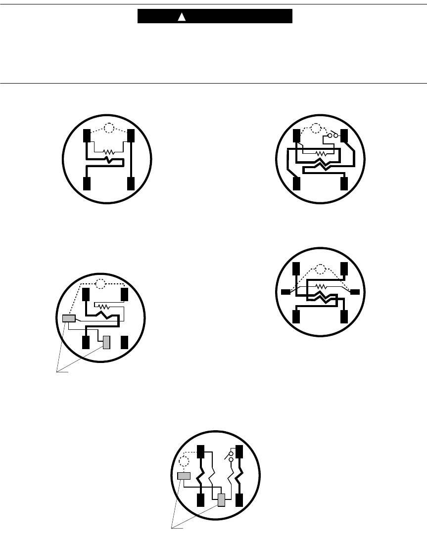
Internal Wiring Diagrams
WARNING
!
Circuit closing devices must be used on current transformer secondaries. This applies to
Form 3S and 4S meters. Dangerous voltages may be present if current transformer
secondaries are open-circuited while the transformer is energized. Equipment damage,
personal injury, or death can result if circuit-closing devices are not used.
Form 1S
PS
PS
Form 2S
Alternate positions of movable
potential terminal
PS
Form 3S
PS
Form 4S
31H05
PS
Form 12S
Alternate positions of movable
potential terminal
December 2007 IL42-4026E
3
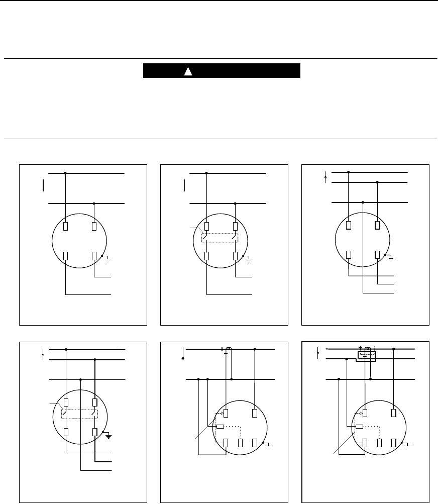
Installation Wiring Diagrams
WARNING
!
Circuit closing devices must be used on current transformer secondaries. This applies to
Form 3S and 4S meters. Dangerous voltages may be present if current transformer
secondaries are open-circuited while the transformer is energized. Equipment damage,
personal injury, or death can result if circuit-closing devices are not used.
N
1
L
O
A
D
1
N
1
N
Form 1S
1 phase, 2 wire
self–contained
20E01
1
2
N
L
O
A
D
2
N
1
N
2
1
Form 2S
1 phase, 3 wire
self–contained
20E01
N
1
L
O
A
D
1
N
1
N
Form 1S (service control switch)
1 phase, 2 wire
self–contained
13L07
Service
control
switch
Form 3S
1 phase, 3 wire
1 CT, no VTs
11G03
1
2
N
N
2
1
CIRCUIT
CLOSING
DEVICE
Form 3S
1 phase, 2 wire
1 CT, no VTs
11G03
1
N
N
1
CIRCUIT
CLOSING
DEVICE
1
2
N
L
O
A
D
2
N
1
N
2
1
Form 2S (service control switch)
1 phase, 3 wire
self–contained
13L07
Service
control
switch
IL42-4026E December 2007
DISCLAIMER OF WARRANTIES AND LIMITATIONS OF LIABILITY
There are no understandings, agreements, representations, or warranties either express or implied, including warranties of
merchantability or fitness for a particular purpose, other than those specifically set out by any existing contract between the parties. Any
such contract states the entire obligation of the seller. The contents of this document shall not become part of or modify any prior
existing agreement, commitment, or relationship.
The information, recommendations, descriptions, and safety notices in this document are based on Elster experience and judgment with
respect to operation and maintenance of the described product. This information should not be considered as all-inclusive or covering all
contingencies. If further information is required, Elster should be consulted.
No warranties, either expressed or implied, including warranties of fitness for a particular purpose or merchantability, or warranties arising
from the course of dealing or usage of trade, are made regarding the information, recommendations, descriptions, warnings, and
cautions contained herein.
In no event will Elster be responsible to the user in contract, in tort (including negligence), strict liability or otherwise for any special,
indirect, incidental, or consequential damage or loss whatsoever, including but not limited to: damage or loss of use of equipment, cost
of capital, loss of profits or revenues, or claims against the user by its customers resulting from the use of the information,
recommendations, descriptions, and safety notices contained herein.
Elster
Raleigh, North Carolina USA
*IL42-4026E*
© 2007 by Elster.
All rights reserved.
Printed in the United States.
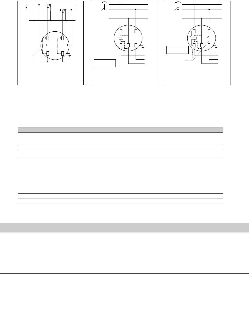
Form 4S
1 Phase, 3 Wire
2 CTs, no VTs
11G03
1
2
N
N
2
1
CIRCUIT
CLOSING
DEVICE
L
O
A
D
2
N
1
1
2
N
N
2
1
Form 12S
2 phase, 3 wire wye
self–contained
20E01
L
O
A
D
2
N
1
1
2
N
N
2
1
Form 12S (service control switch)
2 phase, 3 wire wye
self–contained
13L07
Service
control switch
120/208 service
voltage only
120/208 service
voltage only
FCC and Industry Canada Compliance
Compliance Statement (Part 15.19): This equipment complies with Part 15 of the FCC Rules and with RSS-210 of Industry Canada. Operation is subject to the
following two conditions: 1) This device may not cause harmful interference, and 2) This device must accept any interference received, including interference that
may cause undesired operation.
Warning (Part 15.21): Changes or modifications not expressly approved by Elster could void the user’s authority to operate the equipment.
RF Radiation Safety Guidelines per Part 2 of FCC Rules and Regulations: The meter should be installed in a location where there will be a separation greater
than 20 cm from locations occupied by humans.
User Information (Part 15.105): This equipment has been tested and found to comply with the limits for a Class B digital device, pursuant to part 15 of the FCC
Rules. These limits are designed to provide reasonable protection against harmful interference in a residential installation. This equipment generates, uses and
can radiate radio frequency energy and, if not installed and used in accordance with the instructions, may cause harmful interference to radio communications.
However, there is no guarantee that interference will not occur in a particular installation. If this equipment does cause harmful interference to radio or television
reception, the user is encouraged to try to correct the interference by one or more of the following measures:
■
Reorient or relocate the receiving antenna.
■
Move the receiving equipment farther away from the meter.
■
Consult the dealer or an experienced radio/TV technician for help.
Industry Canada Statement: The term “IC” before the certification/registration number only signifies that the Industry Canada technical specifications were met.
Collocation Statement: Collocation of simultaneously-transmitting (co-transmitting) antennas within 20 cm of each other in a final product is not allowed.