Elster Solutions SRP03 A low power short range programmer interrogator User Manual CERTIFICATE OF COMPLIANCE
Elster Solutions, LLC A low power short range programmer interrogator CERTIFICATE OF COMPLIANCE
Users Manual

Rhein Tech Laboratories AMCO Automated Systems
360 Herndon Parkway
Suite 1400
TRACE Short Range Programmer
FCC ID: G8JSRP03
Herndon, VA 20170 FCC Part 15.231
http://www.rheintech.com RTL WO# 2003077
Page 25 of 39
APPENDIX H: MANUAL
Please see the following pages.

f
TRACE®
S
Sh
ho
or
rt
t
R
Ra
an
ng
ge
e
P
Pr
ro
og
gr
ra
am
mm
me
er
r
V
VR
RT
T
U
U
US
S
SE
E
ER
R
R
G
G
GU
U
UI
I
ID
D
DE
E
E
This page intentionally left blank.
Copyright Acknowledgements
The contents of this document are the property of AMCO Automated
Systems and are copyrighted. All rights reserved. Any reproduction, in
whole or in part, is strictly prohibited. For additional copies of this
document, please contact:
AMCO Automated Systems
107 Erskine Lane
Scott Depot, WV 25560
Phone 304-757-3300 Fax 304-757-3388
The information contained herein has been carefully checked and is
believed to be accurate; however, no responsibility is assumed for
inaccuracies. AMCO Automated Systems reserves the right to make
changes without prior notice. This document is not covered by any
warranty either expressed or implied. Any correction, comments or
additions to the contents of this document should be directed to AMCO
Automated Systems at the above address.
Copyright 2002 AMCO Automated Systems. Printed in USA.
TRACE, Universal RF Interface, URFI, Mini Mobile Interrogator, ReadIt
and TICS are trademarks of AMCO Automated Systems. All rights
reserved.
MS-DOS, IBM and MicroPalm are registered trademarks of their
respective owners.
FCC Compliance
The TRACE Short Range Programmer has been type accepted by the Federal
Communications Commission under Part 15C, low power communication device
transmitter. FCC ID: G8JSRP02
This device complies with Part 15 rules. Operation is subject to the following
conditions:
• This device may not cause harmful interference, and
• This device must accept any interference received, including interference
that may cause undesired operation.
This equipment has been tested and found to comply with the limits for a Class B
digital device, pursuant to part 15 of the FCC Rules. These limits are designed to
provide reasonable protection against harmful interference in a residential
installation. This equipment generates, uses and can radiate radio frequency
energy, and if not installed and used in accordance with the instructions, may
cause harmful interference to radio communications. However, there is no
guarantee that interference will not occur in a particular installation. If this
equipment does cause harmful interference to radio or television reception, which
can be determined by turning the equipment off and on, the user is encouraged
to try to correct the interference by one or more of the following measures:
• Reorient or relocate the receiving antenna.
• Increase the separation distance between the equipment and receiver.
• Connect the equipment into an outlet on a circuit different from that to which
the receiver is connected.
• Consult the dealer or an experience radio/TV technician for help.
Changes or modifications not expressly approved by AMCO Automated Systems
could void the user’s authority to operate the equipment.
This page intentionally left blank.

TABLE OF CONTENTS
Short Range Programmer VRT—User Guide Page 1
P/N 52806T100 Rev 1 April 2003
•
AMCO Automated Systems
Short Range Programmer-VRT
USER GUIDE
Table of Contents
Chapter One—Introduction................................................................................. 2
About this Document ....................................................................................... 2
Audience ................................................................................................... 2
Conventions .............................................................................................. 2
Chapter Two—Short Range Programmer–VRT Overview ............................... 3
SRP and Components..................................................................................... 3
How the SRP Works........................................................................................ 4
Specifications .................................................................................................. 4
Chapter Three—SRP-VRT Operation ................................................................. 5
Keypad Buttons and Functions ....................................................................... 5
SRP Modes ..................................................................................................... 6
Power On/Off................................................................................................... 7
Setting the Time and Date and Broadcast Mode ............................................ 8
How to Interrogate and Program Transponders.............................................. 9
Using Find Mode ....................................................................................... 9
Using Read Meter Index Mode ............................................................... 11
Using Read Pre-divider (and CF) Mode ................................................. 12
Using Program Index (and CF) Mode ..................................................... 13
Using Read History and TOU Mode ....................................................... 15
Using Set Meter Parameters Mode ........................................................ 15
Using Transponder TX Test Mode.......................................................... 15
Charging Batteries......................................................................................... 16
Chapter Four—Troubleshooting ...................................................................... 17

INTRODUCTION CHAPTER 1
Page 2 Short Range Programmer VRT—User Guide
P/N 52806T100 Rev 1 April 2003
•
AMCO Automated Systems
Chapter One
Chapter OneChapter One
Chapter One
Introduction
The TRACE® Short Range Programmer (SRP) is an important part of
AMCO Automated Systems’ portfolio of products for automated meter
reading (AMR) enabling quick and easy initial programming of TRACE
transponders in the field.
About this Document
This Short Range Programmer User Guide provides instructions for
operating the SRP.
Audience
This document is designed for utility industry installers and supervisory
staff. In order to establish appropriate levels of detail for the material, this
document assumes the following:
The user is proficient in reading meters of the type currently
compatible with TRACE transponders and possesses all the skills
necessary to conduct meter reading by conventional means.
The user has little or no prior expertise in the TRACE AMR
technology.
The user is familiar with common data entry devices and techniques.
Conventions
In the interest of brevity and simplicity, this document uses the following
conventions:
Additional information relevant to a given instruction step may be
shown in one of three ways:
1. A bulleted item covers “how-to” and verification information.
2. An italicized NOTE contains relevant background information.
3. An italicized and bolded CAUTION contains information
important to the safety of either the user or the equipment.
• Much of the information in this guide applies to all transponder
firmware (software programs located inside the transponder). Where
the information is unique to Version 9 or VRT firmware, the symbols
(V9) and/or (VRT) will appear in the text.
Where reference to other parties is made, the generic masculine
pronouns (he, his, him) are used. This in no way reflects bias or
gender discrimination in any manner related to the users, publishers
or authors of this document.
CHAPTER 2 SRP-VRT OVERVIEW
Short Range Programmer VRT—User Guide Page 3
P/N 52806T100 Rev 1 April 2003
•
AMCO Automated Systems
Chapter Two
Chapter TwoChapter Two
Chapter Two
Short Range Programmer-VRT Overview
The TRACE Short Range Programmer-VRT (SRP-VRT) is a low power,
short range programmer/interrogator activated by a single button for
ease of use in the field. Designed for initial transponder programming,
the SRP’s maximum range is limited so that it can only communicate
with the nearest transponder.
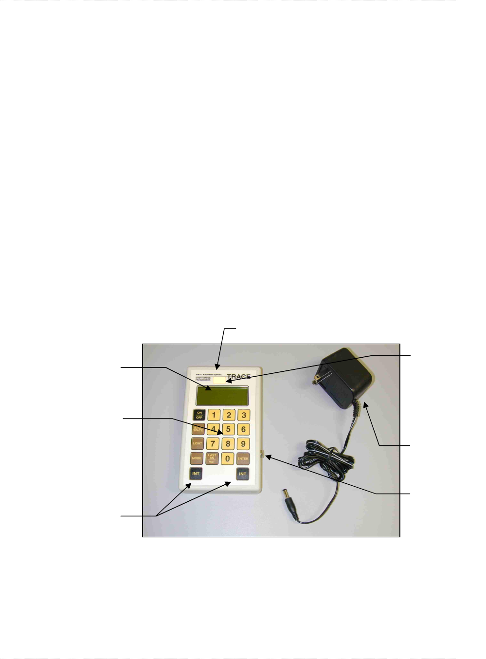
SRP and Components
The SRP is a one-piece handheld unit containing rechargeable batteries.
An internal antenna located near the top of the unit provides both
transmit and receive communications. An external power supply allows
the user to recharge the internal batteries.
The SRP is shipped with the following components:
• SRP handheld unit
• External power supply with cable and connector
SRP Handheld Unit. The handheld SRP unit has a four-line by 20-
character LCD display and an 18-button keypad, which includes five
function keys and two Interrogate (INT) keys. The charging jack is
located on the right-hand side of the unit.
4 line by 20 character
LCD display
17 button keypad
Charging jack
6 volt charging
power supply
Internal antenna for transmit and receive
2 INTERROGATE
buttons
VRT
Label indicating
SRP is VRT-
compatible

SRP-VRT OVERVIEW CHAPTER 2
Page 4 Short Range Programmer VRT—User Guide
P/N 52806T100 Rev 1 April 2003
•
AMCO Automated Systems
Range. The SRP’s range extends outward to approximately twelve (12)
inches from the top of the handheld unit. Actual communication range
may vary dependent upon environmental conditions.
Battery Life. The internal battery allows approximately 24 hours of
normal operation on a single charge. Recharging takes about 2 hours.
How the SRP Works
The SRP is both an interrogator (can talk to and receive information from
transponders) and a programmer (can program transponders). It sends
out a radio frequency (RF) signal embedded with special authorization
codes that the transponder recognizes, and thus establishes
communications with the transponder for performing various functions.
It is designed to operate at short range (within about 12 inches of the
transponder) for programming transponders with the current meter index
value (and other parameters) at the time of installation. This range
limitation helps ensure the SRP programs only the intended transponder
and reads back that same transponder’s status to verify its programming.
The SRP has functions built into its internal programming (firmware) that
allow the user to determine precisely which transponder is being read
and/or programmed. It also allows the user to search for a specific
transponder by serial number if there are a number of transponders in
the area.
With the SRP, the user can also determine and reset the tamper status
of transponders, read meter index data and synchronize transponder
time with SRP time.
Specifications
The following table shows the SRP specifications:
Power UL approved, rechargeable batteries
RF Transmitter Frequency: 451.35 MHz
RF Receiver Frequency: 415 MHz
FCC Compliance The SRP has been type accepted by the FCC for use under Part 15C
FCC ID G8JSRP02
Weight 10 oz (approx.), charger 10 oz. (approx.)
Dimensions 3.75 in. x 6.25 in. x 1.375 in.
Operating Temperature 20°F to +140°F
CHAPTER 3 SRP OPERATION
Short Range Programmer VRT—User Guide Page 5
P/N 52806T100 Rev 1 April 2003
•
AMCO Automated Systems
Chapter Three
Chapter ThreeChapter Three
Chapter Three
SRP Operation
The SRP makes programming transponders quick, easy and reliable. Its
limited range (about 12 inches)—along with its ability to locate individual
transponders by serial number—ensure the SRP programs only the
intended transponder. Verification of the new data is a snap with one
touch of a button.
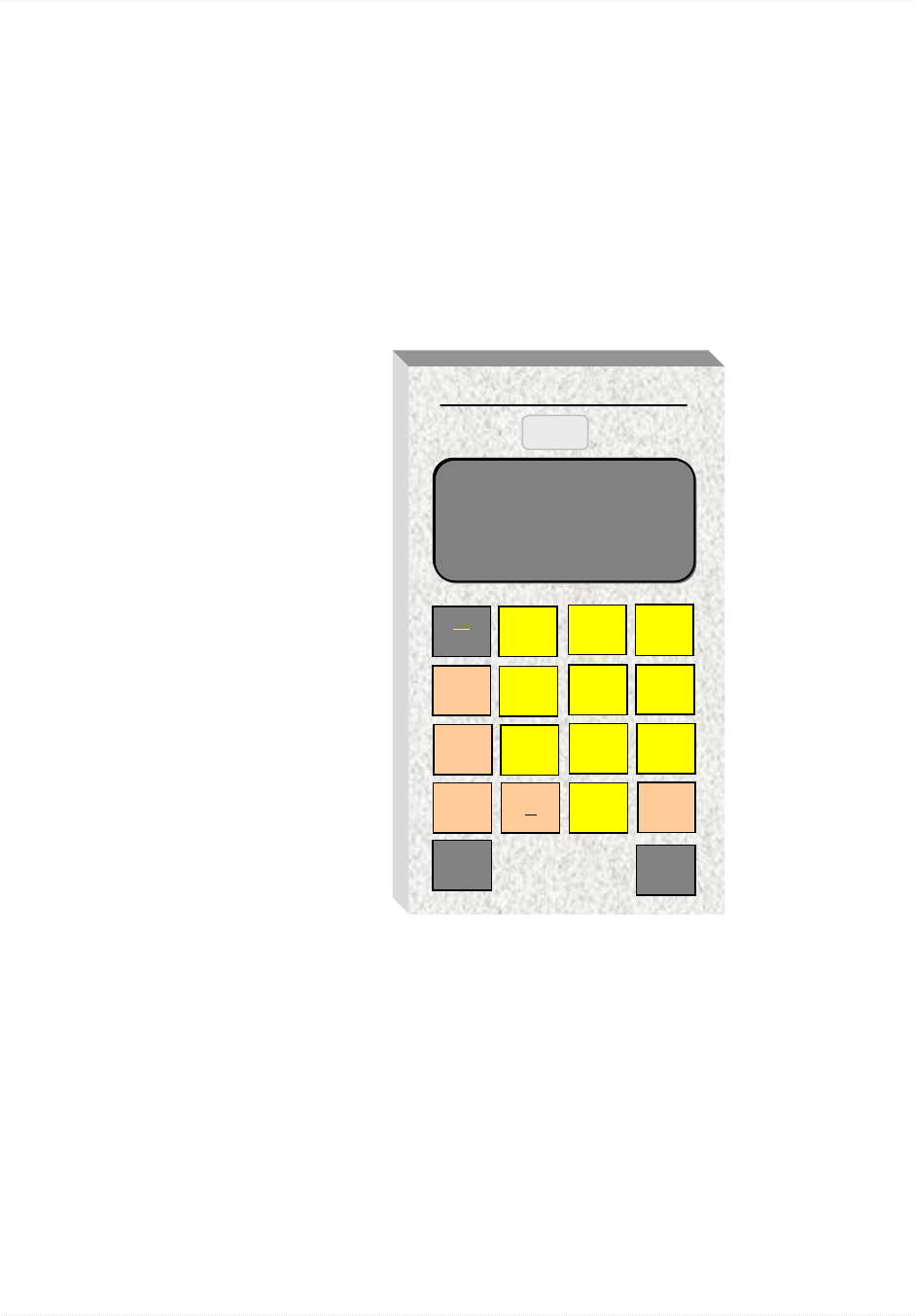
Keypad Buttons and Functions
The SRP keypad has 16 small buttons and two identical “INT”
(interrogate) buttons at the bottom. The five tan buttons represent user-
accessible SRP functions. The yellow number buttons allow you to enter
numerical data manually.
ON/OFF. Alternately turns the SRP on and off. The SRP automatically
shuts off after 2 minutes of non-use to conserve battery power.
TRACE
A
merican Meter
SHORT RANGE
PROGRAMMER
ON
OFF
BACK
SPACE
LIGHT
MODE
12
4
3
56
789
LAS
T
SN
WC 0ENT ER
INT
VRT
INT

SRP OPERATION CHAPTER 3
Page 6 Short Range Programmer VRT—User Guide
P/N 52806T100 Rev 1 April 2003
•
AMCO Automated Systems
BACK SPACE. Moves the cursor (dark flashing box) back one position
to allow the user to change the character displayed in the cursor’s
position.
LIGHT. Alternately turns the display backlight on and off. Backlight uses
battery power and should be turned off when not needed.
MODE. Cycles through all SRP functional modes, advancing one mode
per press of the button.
LAST SN/WC. Toggles between the last successfully interrogated serial
number (LAST SN) and wild card (WC).
ENTER. Moves the cursor from one input field to the next on the
displayed screen.
INTERROGATE. Searches for and initiates communication with the
selected transponder (if a serial number was entered) or the nearest
transponder (if Wild Card is used). This button is also used to program
the baseline meter reading, correction factor (V9 and VRT) and a variety
of other features (VRT) into transponders.
SRP Modes
The SRP has eight functional modes for a variety of operations.
1. Clock – 24 Hour Format Mode. Allows the user to set the current
time and date into the SRP.
• When interrogating any transponder the SRP may also
broadcast its current time. If the SRP is in Broadcast Mode, all
VRT transponders within range of the interrogation will reset their
internal clocks to match the SRP time.
2. FIND SN/VERS/TYPE Mode. Allows you to read and display the
transponder’s serial number, type and firmware version.
• You can interrogate transponders either by using the Wild Card
option (to search for any nearby transponders) or by entering a
specific transponder serial number.
• Once the SRP has read the desired transponder, you are ready
to perform other functions and switch to other modes as
required.
• NOTE: Find is the only mode in which interrogation acquires
transponder firmware version and type information needed for
other operations.

CHAPTER 3 SRP OPERATION
Short Range Programmer VRT—User Guide Page 7
P/N 52806T100 Rev 1 April 2003
•
AMCO Automated Systems
3. READ METER INDEX Mode. Reads the transponder’s electronic
index (e-index).
• From this mode, you can also press “INT” (interrogate) to read
the transponder’s serial number and any tamper flags set during
or since installation.
4. READ PRE-DIVIDER and CF Mode. Reads the sub-count, pre-
divider and compensation factor (V9 and VRT) recorded in the
transponder.
5. Read History / TOU Mode (VRT). Reserved for factory use only.
Reads and programs the transponder time-of-use accumulators and
history. Also reads the transponder current date and time.
6. Set Meter Parameters Mode (VRT). Reserved for factory use only.
Programs the transponder’s date, time and pre-divider.
7. PROGRAM METER INDEX Mode. Programs the meter index value
into the transponder. This mode can also be used to program the
compensation factor into the transponder (V9 and VRT).
8. Transponder TX Test Mode. Reserved for factory use only. This
diagnostic mode is used by the manufacturer to gauge the
performance of a transponder’s transmitter.
Power On/Off
The SRP is powered by rechargeable batteries providing about 24 hours
of normal operation between recharges.
Turning the SRP ON
Press the ON/OFF button once to turn the SRP on.
• Power-on Screen. Each time it is turned on, the SRP conducts a
self-test. The screen displays the SRP firmware version, current
battery voltage, and one of two messages, either “Battery Voltage:
X.XX” (where X.XX is voltage) or “RECHARGE BATTERY.”
• If “RECHARGE BATTERY” appears, you need to recharge the
batteries (indicating a voltage of 1.99 or less). If this message
appears with known fully charged batteries, contact AMCO
Automated Systems.
AMCo, Automated
Systems, SRP
V01.04.00 10-22-02
Battery Voltage: 2.55

SRP OPERATION CHAPTER 3
Page 8 Short Range Programmer VRT—User Guide
P/N 52806T100 Rev 1 April 2003
•
AMCO Automated Systems
Turning the SRP OFF
Manual Power-off. Pressing the ON/OFF button at any time during
operation will power off the SRP. The last transponder serial number
successfully interrogated will be saved.
Automatic Power-off. After 2 minutes of non-use, the SRP will
automatically power off to conserve the battery.
Setting Time and Date and Broadcast Mode
The user can set the current time and date in the SRP and also in the
VRT Transponders by using the optional “Broadcast Time” feature.
In this mode the SRP will broadcast its current time during each
interrogation and VRT transponders will reset their time according to the
broadcast. For these reasons, it is important that the SRP time be
accurate when VRT transponders will be within range of any SRP
interrogation.
The Broadcast Time feature is always reset to “Off” when the SRP is
turned off, but may be turned on as described in the following steps.
Accessing Time and Date Set Mode
1. Press the MODE button until the SRP Time and Date Set mode
(“Clock-24 Hour Format”) displays.
2. Verify the date and time are correct.
To Change Date or Time
1. Press the LAST SN/WC button.
2. Press the ENTER button to skip correct values and move to value(s)
you wish to change.
3. (Date) Enter the correct date using the SRP keypad and press
ENTER.
4. (Time) Enter the correct time using the SRP keypad and press
ENTER
Clock-24 Hour Format
Date: 10-04-02
Time: 08:30:24
Broadcast Time OFF

CHAPTER 3 SRP OPERATION
Short Range Programmer VRT—User Guide Page 9
P/N 52806T100 Rev 1 April 2003
•
AMCO Automated Systems
To Turn Broadcast Time ON and OFF
1. To Turn Broadcast Time ON: Press ENTER while in the Clock-24
Hour Format screen.
• If the time and date settings are already correct, you can simply
press ENTER to turn Broadcast Time ON.
• If you wish to change time or date settings, do so, then press
ENTER to record the changes and switch Broadcast Time to ON.
• The SRP will now transmit its current time at each transponder
interrogation.
• NOTE: Broadcast Time will default to the “Off” setting when you
turn off the SRP. However, your latest time and date settings will
be preserved in SRP memory.
2. To turn Broadcast Time OFF: Switch the SRP off and back on again.
• Broadcast Time is always reset to OFF when the SRP is
powered off.
• Your latest time and date settings are preserved, even when the
SRP is turned off.
How to Interrogate and Program Transponders
In order to program a transponder you must first locate it and interrogate
(read) it to verify that it is the one you want and to determine its
characteristics. This is referred to as “finding” the transponder.
The Find mode identifies the transponder’s firmware version, which, in
turn, tells the SRP which modes can be used with that transponder.
Using Find Mode
To Find a Transponder
1. Press the MODE button repeatedly until the display shows the “Find
Serial Number” screen:
If no serial number is currently displayed and you want to find a
specific transponder:
2. Enter the serial number of the transponder you want...
or...
FIND SN/VERS/TYPE
Serial No.. ????????
? = W.C.

SRP OPERATION CHAPTER 3
Page 10 Short Range Programmer VRT—User Guide
P/N 52806T100 Rev 1 April 2003
•
AMCO Automated Systems
Press the LAST SN/WC button to display the serial number of the
last transponder successfully “found.”
If a serial number is currently displayed and you want to find all
transponders within range:
3. Press the LAST SN/WC button to change the display to ‘Wild Card’
(all question marks).
• This will list all transponders within range of the SRP.
To Interrogate a Transponder
1. Hold the SRP close to the transponder and press either of the two
INT (interrogate) buttons.
• If the interrogation is successful, the screen will display the
transponder serial number, meter type and transponder firmware
version:
• If the interrogation is NOT successful, the screen will display the
“CARRIER NOT DETECTED” message (indicating no signal
from transponder) or “RECEIVE DATA ERROR” (indicating radio
signal interference). This message displays for 2 seconds
(during which time the SRP will not interrogate), then returns to
the initial mode screen.
2. If the interrogation is NOT successful, move the SRP to a slightly
different position relative to the transponder (closer, farther away or
to one side) and interrogate again.
• Radio waves can bounce off of, or be absorbed or deflected by,
various materials (especially metals) which can create
differences in signal strength from one spot to another.
FIND SN/VERS/TYPE
Serial No.. 03571641
TYPE=GAS VERS=09
FIND SN/VERS/TYPE
Serial No.. ????????
INTERROGATING

CHAPTER 3 SRP OPERATION
Short Range Programmer VRT—User Guide Page 11
P/N 52806T100 Rev 1 April 2003
•
AMCO Automated Systems
Using Read Meter Index Mode
This mode reads the meter index (meter count). It will display whole units
only. (For pre-divider/sub-count values use Read Pre-divider mode.)
1. Press the MODE button repeatedly until the display shows the “Enter
Read Meter Index” screen.
2. Acquire the transponder serial number.
• Acquire serial number either: (a) by using the Find mode first or
(b) by manually entering the serial number in this mode.
3. Press one of the two INT (interrogate) buttons.
• If the interrogation is successful, the SRP will display the
transponder serial number, the current meter index value and the
tamper indicator, if applicable (as shown below):
• Any TAMPER indication that appears will not appear again on
the next interrogation. (Tampers are automatically “cleared” after
interrogation.)
• If the interrogation is NOT successful, the screen will display the
“CARRIER NOT DETECTED” message (indicating no signal
from transponder) or “RECEIVE DATA ERROR” (indicating radio
signal interference). These messages display for 2 seconds,
during which time the SRP will not interrogate..
4. If the interrogation is NOT successful, move the SRP to a slightly
different position relative to the transponder (closer, farther away, or
to one side) and interrogate again.
• Radio waves can bounce off of, or be absorbed or deflected by,
various materials (especially metals) which can create slight
differences in signal strength from one spot to another.
READ METER INDEX
Serial No.. ???????
READ METER INDEX
Serial No.. ???????
INDEX NO.. 00001234
TAMPER

SRP OPERATION CHAPTER 3
Page 12 Short Range Programmer VRT—User Guide
P/N 52806T100 Rev 1 April 2003
•
AMCO Automated Systems
Using Read Pre-divider (and CF) Mode
This mode reads the current sub-counts and pre-divider along with the
current compensation factor (V9 and VRT).
NOTE: The CF displays with the pre-divider only if the transponder
firmware supports CF and this can only be determined if the transponder
is interrogated first in the Find mode.
1. Press the MODE button repeatedly until the display shows either of
the two “Read Pre-divider” screens below:
• For transponders accessed directly through Pre-divider mode:
• For V9 and VRT transponders interrogated in Find mode:
2. If the serial number represents the target transponder, go to step 4.
3. If Find mode was not used, or the displayed serial number is not the
serial number of the target transponder, enter the serial number of
the desired transponder.
4. Press either of the two INT (interrogate) buttons to read the pre-
divider (and CF if applicable).
• If interrogation is successful, the screen will display the serial
number and pre-divider (and CF if applicable) as shown in the
examples below:
• The pre-divider is displayed in the form SSS/PPP where SSS is
the current sub-count and PPP is the actual pre-divider.
READ PRE-DIVIDER
Serial No.. 03571641
PRE-DIV... = 001/100
READ PRE-DIVIDER
Serial No.. 03571641
READ PRE-DIV and CF
Serial No.. 03571641

CHAPTER 3 SRP OPERATION
Short Range Programmer VRT—User Guide Page 13
P/N 52806T100 Rev 1 April 2003
•
AMCO Automated Systems
• For V9 and VRT transponders which were interrogated in Find
mode, the compensation factor also displays on the lower line:
• If the interrogation is NOT successful, the screen will display the
“CARRIER NOT DETECTED” message (indicating no signal
from transponder) or “RECEIVE DATA ERROR” (indicating radio
signal interference). This message displays for 2 seconds, during
which time the SRP will not interrogate.
5. If the interrogation is NOT successful, move the SRP to a slightly
different position relative to the transponder (closer, farther away, or
to one side) and interrogate again.
• Radio waves can bounce off of, or be absorbed or deflected by,
various materials (especially metals) which can create slight
differences in signal strength from one spot to another.
Using Program Index (and CF) Mode
This mode programs the current meter index value and compensation
factor (V9 and VRT).
NOTE: The compensation factor may be programmed only if the
transponder firmware supports CF and this can only be determined if the
transponder was interrogated first in the Find mode.
1. Press the MODE button repeatedly until the display shows either of
the following two Program Index (and CF) screens:
• For transponders accessed directly in Program Index (and CF)
mode:
READ PRE-DIV and CF
Serial No.. 03571641
PRE-DIV... 001/100
COMP FACT.= 200/250
PROGRAM METER INDEX
Serial No.. 03571641
Index No... 00001348

SRP OPERATION CHAPTER 3
Page 14 Short Range Programmer VRT—User Guide
P/N 52806T100 Rev 1 April 2003
•
AMCO Automated Systems
• For V9 and VRT transponders which were interrogated in
Find mode the compensation factor ratio also displays on the
lower line:
2. If the serial number represents the target transponder, go to step 4.
3. If Find mode was not used or the serial number displayed is not the
serial number of the target transponder, enter the desired serial
number.
• To enter serial number, press the ENTER button until the cursor
(flashing dark box) appears over the first digit of the Serial No.
input field. Enter the serial number. Press the ENTER button
when completed.
4. Read the meter conventionally (visually, from the mechanical index).
• The SRP display will also show the CF Ratio (where applicable).
5. Enter the meter index value using the SRP keypad.
• This field requires 7 digits. Read and enter index value from left
to right, just as you would normally read and write any numerical
value. Include as many leading zeroes as are needed to fill
positions to the left of the meaningful digits.
6. Enter the compensation factor using SRP keypad. (V9 and VRT
transponders)
• CF Ratio obtained in step 4 (where applicable).
• To enter the CF value, press the ENTER button until the cursor
(flashing dark box) appears over the CF Ratio numerator (top
number) and/or denominator (bottom number). Enter the correct
value. Press the ENTER button when completed.
7. Press either of the two INT (interrogate) buttons.
• This programs the baseline meter index value and compensation
factor (v9 and VRT) into the transponder memory.
• If programming is successful, the SRP will display the
“PROGRAM VERIFIED” message.
• If programming is NOT successful, the screen will display the
“PRGRM COMPARE ERROR” message.
PROGRAM METER INDEX
Serial No.. 03571641
Index No... 00001348
CF Ratio... 001/001

CHAPTER 3 SRP OPERATION
Short Range Programmer VRT—User Guide Page 15
P/N 52806T100 Rev 1 April 2003
•
AMCO Automated Systems
8. If the interrogation is NOT successful, move the SRP to a slightly
different position relative to the transponder (closer, farther away, or
to one side) and interrogate again.
• Radio waves can bounce off of, or be absorbed or deflected by,
various materials (especially metals) which can create slight
differences in signal strength from one spot to another.
Using Read History and TOU Mode (VRT)
Reserved for factory use only.
This mode reads the transponder time-of-use (TOU) accumulators and
history.
NOTE: Should you need to read transponder TOU, Daily History and
other factory-installed defaults using the SRP, contact Customer Service
at AMCO Automated Systems.
Using Set Meter Parameters Mode (VRT)
Reserved for factory use only.
This mode programs the transponder’s date, time and pre-divider.
NOTE: Should you need to reprogram transponder TOU, Daily History
and other factory-installed defaults using the SRP, contact Customer
Service at AMCO Automated Systems.
Using Transponder TX Test Mode
Reserved for factory use only.
NOTE: This is an in-shop transponder transmitter diagnostic tool used by
the manufacturer.
SRP OPERATION CHAPTER 3
Page 16 Short Range Programmer VRT—User Guide
P/N 52806T100 Rev 1 April 2003
•
AMCO Automated Systems
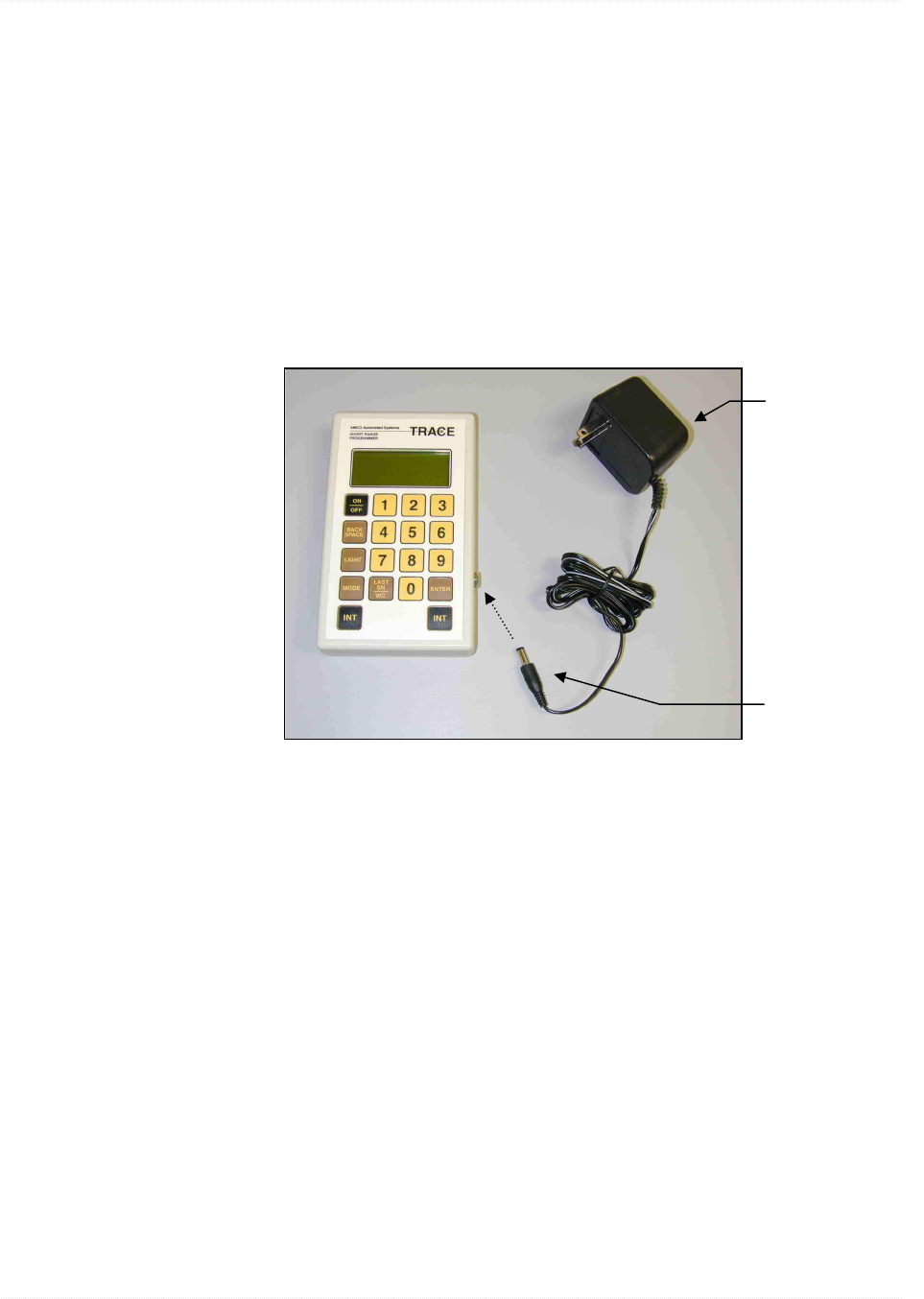
Charging Batteries
The SRP batteries typically deliver between 2.0 volts and (when fully
charged) 2.6 volts If the voltage drops near 2.0 (as shown on the power-
on screen), you should recharge the batteries.
Battery charger. A 6 volt external power supply allows you to recharge
the internal batteries by connecting the SRP to the charger and plugging
the charger into a standard 120 VAC outlet. The SRP can be operated
while it is charging if needed to troubleshoot transponders in the shop.
CAUTION: When the battery is completely dead, it may take up to 15
minutes on charge before the unit will resume operation.
Battery charger.
Plug into 120 VAC
wall outlet
Connect charger jack
to
po
r
t
o
n
S
RP

CHAPTER 4 TROUBLESHOOTING
Short Range Programmer VRT—User Guide Page 17
P/N 52806T100 Rev 1 April 2003
•
AMCO Automated Systems
Chapter Four
Chapter FourChapter Four
Chapter Four
Troubleshooting
The following table offers troubleshooting tips for some common SRP
conditions. For all other matters, contact AMCO Automated Systems.
Symptom Possible Cause Solution
Upon start-up, SRP displays
“RECHARGE BATTERY”
message.
Battery voltage too low. Recharge batteries.
Upon interrogation, SRP displays
the “CARRIER NOT DETECTED”
message and does not display
transponder data.
The SRP is out of range of the
transponder.
Move the SRP (and particularly the top, where
antenna resides) closer to the transponder.
The SRP is receiving outside
interference.
Move the SRP (and particularly the top, where
antenna resides) closer to the transponder. If
other TRACE readers or programmers are
operating nearby, wait until they have moved
away and try again.
Manually entered transponder serial
number is not valid.
Wait 2 seconds, re-enter the desired serial
number and interrogate again. If interrogation fails
again, check source of serial number and
verify/correct number.
Transponder is not responding to
interrogation signal.
Move the SRP (and particularly the top, where
antenna resides) closer to the transponder. If
other TRACE readers or programmers are
operating nearby, wait until they have moved
away and try again.
First History/TOU or Set Meter
Parameters program command
interrogation (VRT).
Interrogate for the second time.
Second or subsequent History/TOU or
Set Meter Parameters program
command interrogation attempted
beyond 1 minute timeout (VRT).
Restart command sequence by re-entering
transponder serial number in SN-ADR/CMD field
and interrogating. Repeat command
interrogation.
Upon interrogation, SRP displays
“READ DATA ERROR.”
The SRP is receiving outside
interference.
Move the SRP (and particularly the top, where
antenna resides) closer to the transponder. If
other TRACE readers or programmers are
operating nearby, wait until they have moved
away and try again.
Two or more transponders are within in
range of the SRP simultaneously.
Set the SRP (and particularly the top, where
antenna resides) directly on the desired
transponder.

TROUBLESHOOTING CHAPTER 4
Page 18 Short Range Programmer VRT—User Guide
P/N 52806T100 Rev 1 April 2003
•
AMCO Automated Systems
Symptom Possible Cause Solution
Upon attempting to read or
program index or pre-divider, SRP
displays “Wild Card Not Valid”
message.
These operations do not allow the Wild
Card option.
Enter serial number manually or obtain serial
number via Find mode.
Upon interrogation, SRP displays
“CS/LOAD ERR” and “TAMPER”
messages.
This occurs normally at first interrogation
after a transponder has been powered
up (either new or reset).
Interrogate again to clear messages.
Upon interrogation, SRP displays
“CKSUM ER” message.
This occurs normally after the second
interrogation of a new or reset
transponder and will remain until
transponder is programmed.
Program transponder.