Elster Solutions UFTR1 Unified Field Tool User Manual 17 3005 Manual
Elster Solutions, LLC Unified Field Tool 17 3005 Manual
Manual

2320 Presidential Drive, Suite 101, Durham, NC 27703 USA Voice: 919-381-4235
Certification Exhibit
FCC ID: QZC-UFTR1
IC: 4557A-UFTR1
FCC Rule Parts: 15.247, Part 90
ISED Canada’s Radio Standards Specifications: RSS-247, RSS-119
ACS Project Number: 17-3005
Manufacturer: Elster Solutions
Model: UFTR1
Manual

Model UFT PCBA manual
General
The Model UFT printed circuit board assembly (PCBA) contains a frequency hopping spread spectrum radio
operating in the 902.4-927.6 MHz ISM frequency band and a 451.35 MHz FCC Part 90 licensed radio. It also
contains a pre-certified Bluetooth module used for communication with user’s Bluetooth enabled portable
device. When the UFT module is installed in its plastic housing it forms a pass-through device used to
interrogate Elster Solutions metering devices that are currently installed. Installations of multiple metering
devices comprise part of an Advanced Metering Infrastructure (AMI) system that utilizes a proprietary network
architecture and protocol devised by Elster Solutions. The UFT is used by the user to allow communication with
devices within this network architecture.
Device specifications
Table 1: 900 MHz Radio Specifications for 25-Channel 250 mW EA Operation
Classification
Frequency Hopping Spread Spectrum
Maximum Output Power
250 mW
Operating Frequency Band
902.4
–
927.6 MHz
Number of Channels
25
Channel Spacing
400 KHz
Mode
EA LAN1
EA LAN2
Data Rate
35.56 kbps
142.22 kbps
Occupied Bandwidth – 20dB
250 KHz < BW < 400 KHz
250 KHz < BW < 400 KHz
Occupied Bandwidth – 99%
250 KHz
< BW < 400 KHz
250 KHz < BW < 400 KHz
Channel Dwell Time
< 0.4 seconds within a 10 second period
Table 2: 900 MHz Radio Specifications for 64-Channel 250 MW NGC Operation
Classification
Frequency Hopping Spread Spectrum
Maximum Output Power
250 mW
Operating Frequency Band
902.4
–
927.6 MHz
Number of Channels
64
Channel Spacing
400 KHz
Mode
NGC
Data Rate
50, 150, 200 kbps
FSK Occupied Bandwidth – 20dB
100 KHz < BW < 400 KHz for 50/150/200 kbps data rates
FSK Occupied Bandwidth – 99%
100 KHz < BW < 400 KHz for 50/150/200 kbps data rates
GFSK Occupied Bandwidth – 20dB
100 KHz < BW < 400 KHz for 50/150/200 kbps data rates
Channel Dwell Time
< 0.4 seconds within a 20 second period

Table 3: 451.35 MHz Radio Specifications
Classification
Single Channel GFSK
Maximum Output Power
500 mW
Operating Frequency Band
451.35 MHz
Number of Channels
1
Data Rate
3.125 kHz
Channel Bandwidth
12.5 kHz
Occupied Bandwidth – 99%
10.5 kHz
FCC and Industry Canada Compliance
The 900 and 451.35MHz radio module is manufactured directly onto the main circuit board, and the module is
inserted into the plastic housing that attaches to the user’s belt using the included beltclip. The Bluetooth
module is a pre-certified module (FCC: PI4411B, IC: 1931B-BTM411). The UFT has no user-serviceable parts.
USER INFORMATION (PART 15.105)
This equipment has been tested and found to comply with the limits for a Class B digital device, pursuant to
part 15 of the FCC Rules. These limits are designed to provide reasonable protection against harmful
interference in a residential installation. This equipment generates, uses and can radiate radio frequency
energy and, if not used in accordance with the instructions, may cause harmful interference to radio
communications. However, there is no guarantee that interference will not occur in a particular installation.
If you experience trouble with this equipment, please use the Return Material Authorization (RMA) feature
available at the Online Customer Services at www.elstersolutions.com. Do not attempt to repair this equipment
yourself unless you are replacing the entire module.
COMPLIANCE STATEMENT (FCC PART 15.19 AND INDUSTRY CANADA)
This device complies with part 15 of the FCC Rules and with Industry Canada licence-exempt RSS standard(s).
Operation is subject to the following two conditions: (1) This device may not cause harmful interference, and
(2) this device must accept any interference received, including interference that may cause undesired
operation of the device.
ÉNONCÉ DE CONFORMITÉ
Cet appareil est conforme à la Partie 15 des règles de la FCC et aux CNR d'Industrie Canada applicables aux
appareils radio exempts de licence. L'utilisation de cet appareil est soumise aux deux conditions suivantes : (1)
Cet appareil ne doit pas provoquer d'interférences nocives et (2) cet appareil doit accepter toutes les
interférences reçues notamment celles pouvant provoquer un fonctionnement intempestif de l'appareil.
ANTENNA COMPLIANCE
Under Industry Canada regulations, this radio transmitter may only operate using an antenna of a type and
maximum (or lesser) gain approved for the transmitter by Industry Canada. To reduce potential radio
interference to other users, the antenna type and its gain should be so chosen that the equivalent isotropically
radiated power (e.i.r.p.) is not more than that necessary for successful communication.
Conformément à la réglementation d'Industrie Canada, le présent émetteur radio peut fonctionner avec une
antenne d'un type et d'un gain maximal (ou inférieur) approuvé pour l'émetteur par Industrie Canada. Dans le
but de réduire les risques de brouillage radioélectrique à l'intention des autres utilisateurs, il faut choisir le
type d'antenne et son gain de sorte que la puissance isotrope rayonnée équivalente (p.i.r.e.) ne dépasse pas
l'intensité nécessaire à l'établissement d'une communication satisfaisante.
UFT: This radio transmitter has been approved by Industry Canada to operate with the antenna types listed
below with the maximum permissible gain and required antenna impedance for each antenna type indicated.
Antenna types not included in this list, having a gain greater than the maximum gain indicated for that type, are
strictly prohibited for use with this device.
UFT: Le présent émetteur radio a été approuvé par Industrie Canada pour fonctionner avec les types d'antenne
énumérés ci-dessous et ayant un gain admissible maximal et l'impédance requise pour chaque type d'antenne.
Les types d'antenne non inclus dans cette liste, ou dont le gain est supérieur au gain maximal indiqué, sont
strictement interdits pour l'exploitation de l'émetteur.
•On Board 900MHz Chip Antenna: 2.56 dBi
•External 450 MHz Dipole Antenna: 4 dBi
WARNING (PART 15.21)
Changes or modifications not expressly approved by Elster could void the user's authority to operate the
equipment.
RF RADIATION SAFETY GUIDELINES
This equipment complies with FCC radiation exposure limits set forth for an uncontrolled environment. This
equipment is in direct contact with the body of the user under normal operating conditions. This device should
only be operated in the manner outlined in the training documents provided.
DIRECTIVES DE SÉCURITÉ DE RADIOFRÉQUENCE
Cet équipement est conforme aux limites d'exposition aux rayonnements de la FCC établies pour un
environnement non contrôlé. Cet équipement est en contact direct avec le corps de l'utilisateur dans des
conditions normales d'utilisation. Cet appareil ne doit être utilisé que de la manière indiquée dans les
documents de formation fournis.
COLLOCATION STATEMENT
This transmitter must not be co-located or operating in conjunction with any other antenna or transmitter.
DÉCLARATION DE CO-LOCALISATION
Cet émetteur ne doit pas être co-localisé ou opérant en conjonction avec aucune autre antenne ou
transmetteur.

Unified Field Tool
Product guide
PG42-1064A
Preliminary
Preliminary

UNIFIED FIELD TOOL
The unified field tool (UFT) is a device used for communicating with electric
meters and gas and water modules. It is typically used for installation, but
also used for meter reading and troubleshooting.
The UFT can be used with both EA_Installer and EA_Inspector running on
the Radix FW950 handheld.
This product guide contains the following information:
•FCC and Industry Canada Compliance
•Safety information
-Wearing the UFT with the beltclip
•Before using the UFT with beltclip
-Parts
-Assembly
>Beltclip to UFT device
-Charging the UFT device
•Pairing the UFT with the handheld
Preliminary

Unified Field Tool 2
FCC AND INDUSTRY CANADA COMPLIANCE
The 900 and 451.35MHz radio module is manufactured directly onto the
main circuit board, and the module is inserted into the plastic housing that
attaches to the user’s belt using the included beltclip. The Bluetooth
module is a pre-certified module (FCC: PI4411B, IC: 1931B-BTM411). The
UFT has no user-serviceable parts.
User Information (Part 15.105)
This equipment has been tested and found to comply with the limits for a
Class B digital device, pursuant to part 15 of the FCC Rules. These limits
are designed to provide reasonable protection against harmful interference
in a residential installation. This equipment generates, uses and can
radiate radio frequency energy and, if not used in accordance with the
instructions, may cause harmful interference to radio communications.
However, there is no guarantee that interference will not occur in a
particular installation.
If you experience trouble with this equipment, please use the Return
Material Authorization (RMA) feature available at the Online Customer
Services at www.elstersolutions.com. Do not attempt to repair this
equipment yourself unless you are replacing the entire module.
Compliance Statement (FCC Part 15.19 and Industry Canada)
This device complies with part 15 of the FCC Rules and with Industry
Canada license-exempt RSS standard(s). Operation is subject to the
following two conditions: (1) This device may not cause harmful
interference, and (2) this device must accept any interference received,
including interference that may cause undesired operation of the device.
Énoncé de conformité
Cet appareil est conforme à la Partie 15 des règles de la FCC et aux CNR
d'Industrie Canada applicables aux appareils radio exempts de licence.
L'utilisation de cet appareil est soumise aux deux conditions suivantes : (1)
Cet appareil ne doit pas provoquer d'interférences nocives et (2) cet
appareil doit accepter toutes les interférences reçues notamment celles
pouvant provoquer un fonctionnement intempestif de l'appareil.
Antenna Compliance
Under Industry Canada regulations, this radio transmitter may only operate
using an antenna of a type and maximum (or lesser) gain approved for the
transmitter by Industry Canada. To reduce potential radio interference to
other users, the antenna type and its gain should be so chosen that the
equivalent isotropically radiated power (e.i.r.p.) is not more than that
necessary for successful communication.
Conformément à la réglementation d'Industrie Canada, le présent
émetteur radio peut fonctionner avec une antenne d'un type et d'un gain
maximal (ou inférieur) approuvé pour l'émetteur par Industrie Canada.
Dans le but de réduire les risques de brouillage radioélectrique à l'intention
des autres utilisateurs, il faut choisir le type d'antenne et son gain de sorte
que la puissance isotrope rayonnée équivalente (p.i.r.e.) ne dépasse pas
l'intensité nécessaire à l'établissement d'une communication satisfaisante.
Preliminary
Unified Field Tool 3
UFT: This radio transmitter has been approved by Industry Canada to
operate with the antenna types listed below with the maximum permissible
gain and required antenna impedance for each antenna type indicated.
Antenna types not included in this list, having a gain greater than the
maximum gain indicated for that type, are strictly prohibited for use with
this device.
UFT: Le présent émetteur radio a été approuvé par Industrie Canada pour
fonctionner avec les types d'antenne énumérés ci-dessous et ayant un gain
admissible maximal et l'impédance requise pour chaque type d'antenne.
Les types d'antenne non inclus dans cette liste, ou dont le gain est
supérieur au gain maximal indiqué, sont strictement interdits pour
l'exploitation de l'émetteur.
•On Board 900MHz Chip Antenna: 2.56 dBi
•External 450 MHz Dipole Antenna: 4 dBi
Warning (Part 15.21)
Changes or modifications not expressly approved by Elster could void the
user's authority to operate the equipment.
RF Radiation Safety Guidelines
This equipment complies with FCC radiation exposure limits set forth for an
uncontrolled environment. This equipment is in direct contact with the
body of the user under normal operating conditions. This device should
only be operated in the manner outlined in the training documents
provided.
Directives de sécurité de radio fréquence
Cet équipement est conforme aux limites d'exposition aux rayonnements
de la FCC établies pour un environnement non contrôlé. Cet équipement
est en contact direct avec le corps de l'utilisateur dans des conditions
normales d'utilisation. Cet appareil ne doit être utilisé que de la manière
indiquée dans les documents de formation fournis
Collocation Statement
This transmitter must not be co-located or operating in conjunction with
any other antenna or transmitter.
Déclaration de co-localisation
Cet émetteur ne doit pas être co-localisé ou opérant en conjonction avec
aucune autre antenne ou transmetteur.
Preliminary
Unified Field Tool 4
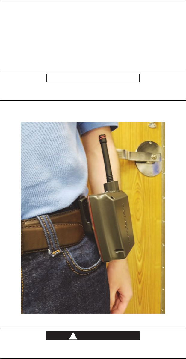
SAFETY INFORMATION
WEARING THE UFT WITH THE BELTCLIP
The device comes with a separate beltclip that attaches to the device and
then to your belt making it easy to carry. You can choose, however, to attach
the beltclip to your belt first and then attach the UFT. The device with
beltclip can be worn anywhere on your belt.
NOTICE
When wearing the UFT with beltclip, be sure that the antenna points
upward and the company name, Honeywell, faces outward.
Figure 1. Correct position for wearing UFT with beltclip
WARNING
!
Misuse of this product outside of the safety wearing guidelines listed
above can result in an increased level of RF exposure.
Preliminary
Unified Field Tool 5
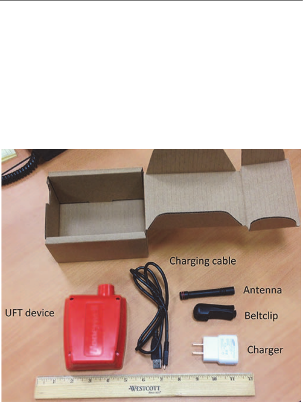
BEFORE USING THE UFT WITH BELTCLIP
PARTS
The parts included in the box are:
•UFT device with antenna attached
•Charging cable and charger
•Beltclip
Figure 2. UFT with parts
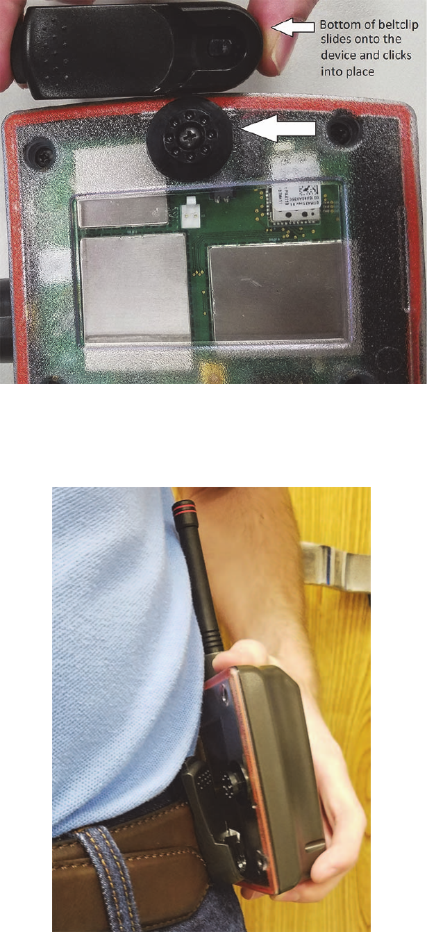
ASSEMBLY
Attaching the UFT to the beltclip
1Place the underside of the beltclip onto the device’s round knob and
push upward on the beltclip to click and lock it into place.
2Attach the clip with the device anywhere on your belt with the antenna
up and the company name, Honeywell, facing out.
Preliminary

Unified Field Tool 7
CHARGING THE DEVICE
Before using the UFT, it must be charged using the enclosed charging
cable. Charge time can take up to 7 hours.
•Insert the USB end of the charging cable into the charger and the small
end into the device’s micro USB port.
•Plug the male end of the charger into an electrical outlet.
Charging should begin immediately, indicated by a solid green light.
PAIRING THE UFT WITH THE FW950 BLUETOOTH HANDHELD
If the device is shipped with the handheld, the two devices have been
paired at the factory.
If the UFT is a replacement device, it must be paired with the FW950
Bluetooth handheld before EA_Inspector or EA_Installer can use it to
communicate with LAN devices. Each time the device is fully discharged, it
must be paired again with the handheld.
Pairing is done using the elsterRegKeyEdit application. This application
is located on the handheld by selecting the options DiskOnChip, Windows,
and ElsterRegKeyEdit. Press Enter after selecting each option to move to
the next window.
Complete these steps to pair the UFT with the handheld.
1Make sure the FW950 handheld is not in the cradle.
2Make sure the Bluetooth Beltclip is charged and on.
3On the handheld main window, select My Device.
4Select these options DiskOnChip, Windows, ElsterRegKeyEdit,
pressing Enter after each one to move to the next window.
5Select RegKeyEdit to run it.
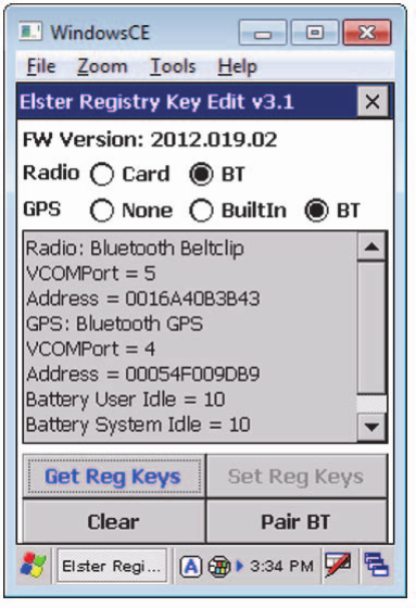
The Elster Registry Key Edit window is displayed.
Table 1. LED indicators
LED color Description
Green solid Comes on immediately when charging cable is
plugged into the device’s USB port and charger, and
the charger is plugged into an electrical outlet. Does
this light stay on with the amber solid light until
charging is completed?
Amber solid Indicates the device is charging; goes off when fully
charged
Green blinking Indicates a good charge
Yellow blinking Indicates that charge is less than 50%
Red blinking Indicates that charge is less than 10%
Preliminary
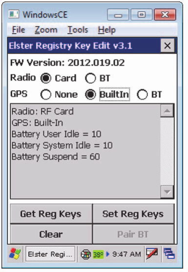
Unified Field Tool 8
Figure 5. Elster Registry Key Edit window
6Select BT as the Radio option.
If Set Reg Keys is enabled, continue now with Step 7.
If Pair BT is enabled, continue now with Step 8.
7Click Set Reg Keys.
A message is displayed asking if you want to enable the handheld
Bluetooth.
8To enable the handheld Bluetooth, click Yes. The handheld reboots.
Continue now with Step 9.
Note: If you click No, the Bluetooth Beltclip setup ends.
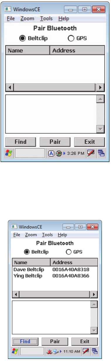
9Click Pair BT to display the Pair Bluetooth screen.
Preliminary
Unified Field Tool 9
Figure 6. Pair Bluetooth screen
10 Select Beltclip and click Find.
The handheld screen displays all Bluetooth Beltclip devices found
around the handheld.
Figure 7. Bluetooth Beltclip devices found
11 Select the device to be paired and click Pair.
When the Bluetooth Beltclip is paired with the FW950 Bluetooth
handheld, the following message is displayed:
Preliminary
Unified Field Tool 10
Pair Bluetooth Beltclip Succeeded
12 Click OK and then click Exit to exit the Pair Bluetooth screen.
The Elster Registry Key Edit screen is displayed.
Figure 8. Elster Registry Key Edit window
13 To confirm the pairing, click Get Reg Keys.
Preliminary
Preliminary

Honeywell Smart Energy
208 S Rogers Lane
Raleigh, NC 27610
+1 800 257 9754 (US toll free)
+1 905 634 4895 (Canada)
© 2017 by Honeywell International Inc. All rights reserved.
Information herein is subject to change without notice.
Product specifications may change. Contact your
Honeywell electricity metering representative for the most
current product information.
Produced in the United States.
www.HoneywellSmartEnergy.com
Preliminary