Elster Solutions URF01 URFI User Manual Part 90
Elster Solutions, LLC URFI Part 90
UserManual.wiki
>
Elster Solutions
>
URF01 User Manual
>
Manual
Contents
1.
User Manual
2.
Manual
Manual
Navigation menu
Upload a User Manual
Namespaces
Wiki Guide
HTML
PDF
Info
Views
User Manual
Discussion / Help
Navigation
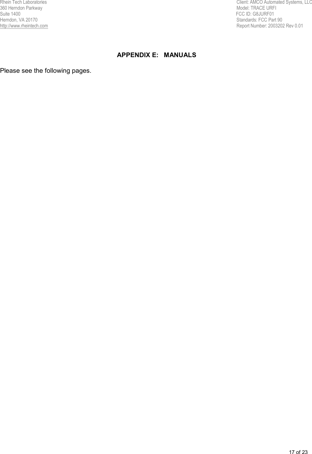

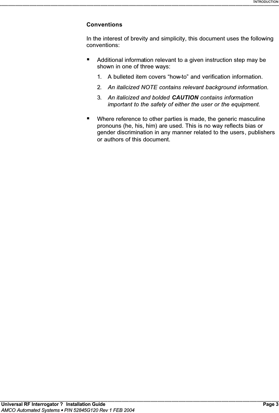

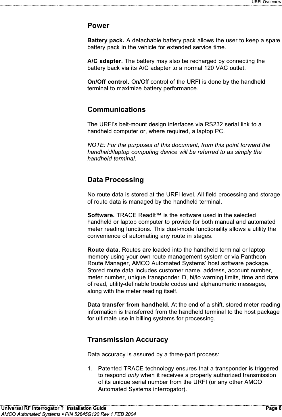


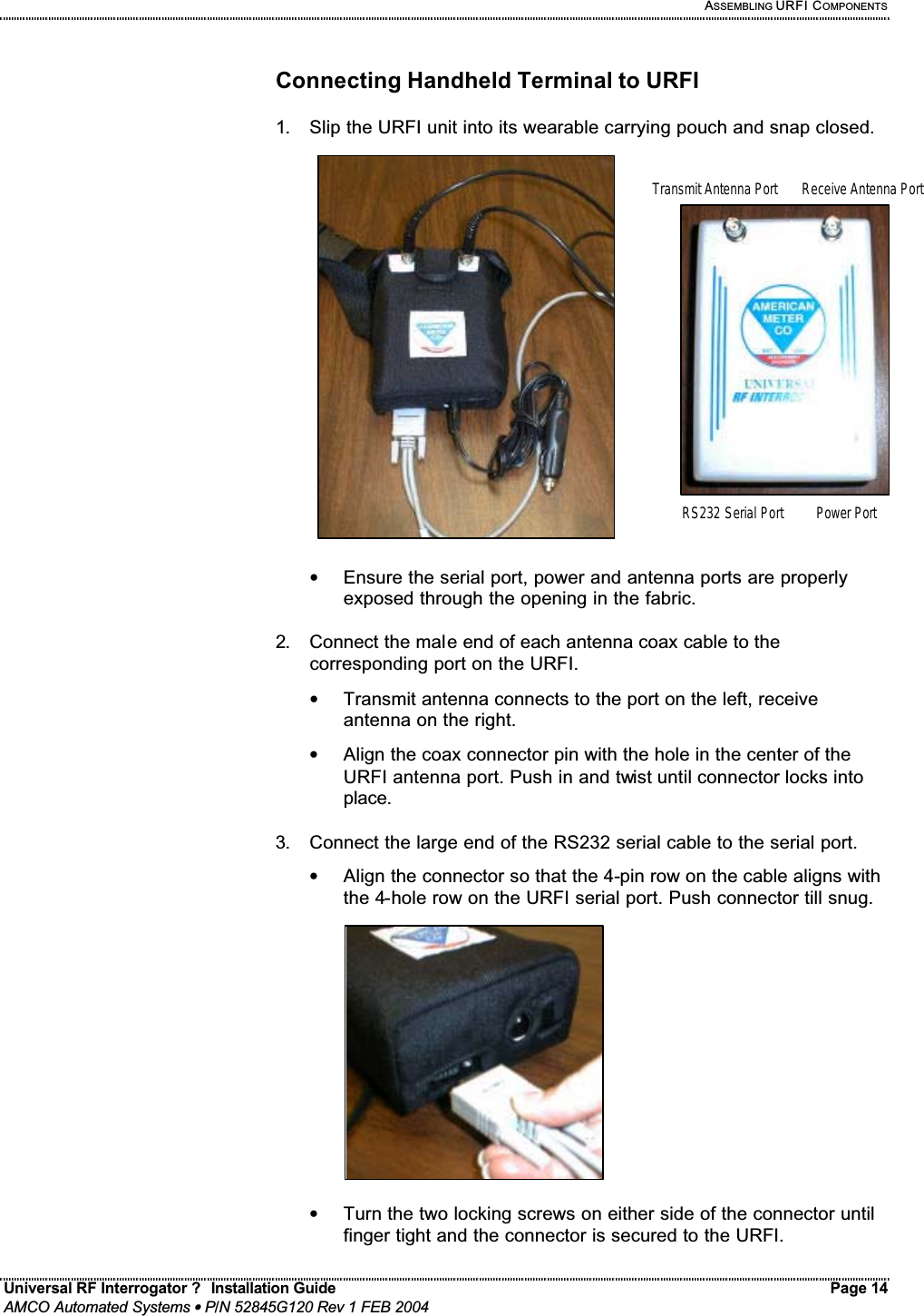
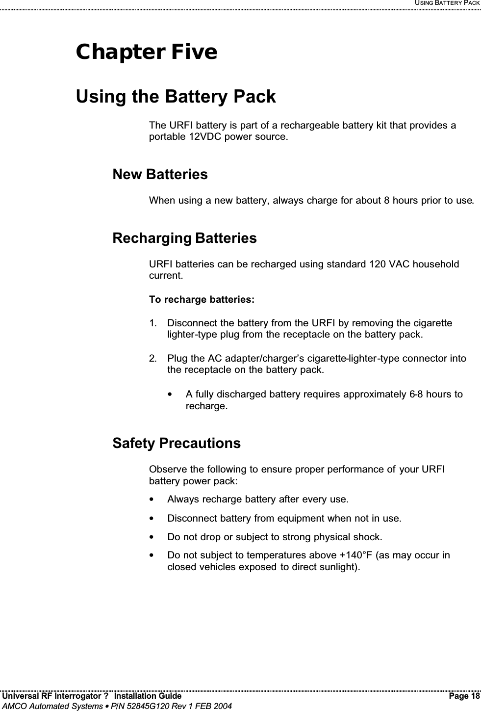

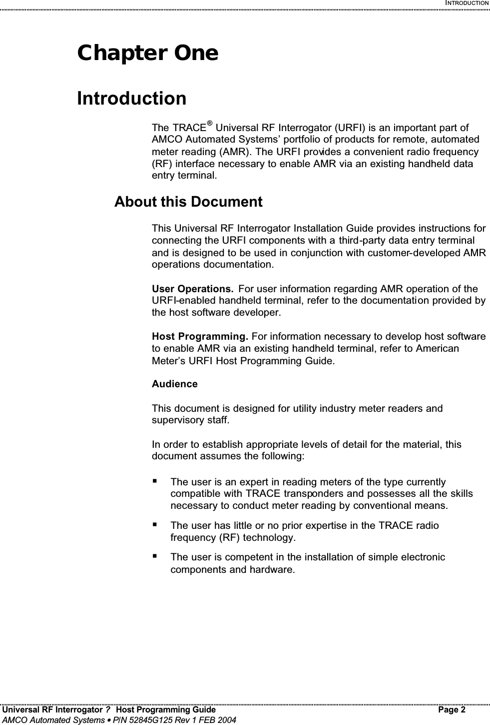

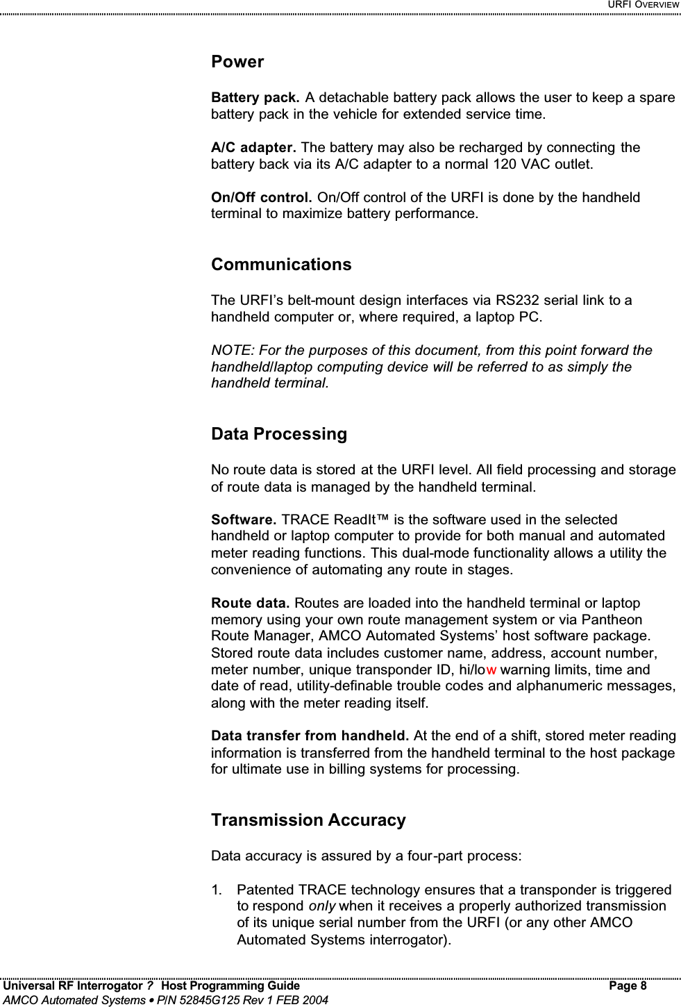
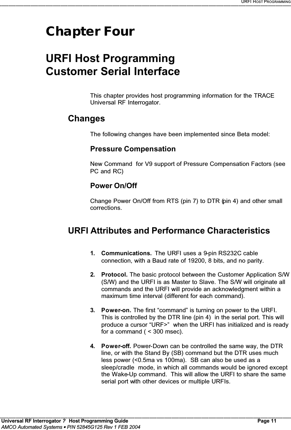
![URFI HOST PROGRAMMING Universal RF Interrogator ? Host Programming Guide Page 13 AMCO Automated Systems • P/N 52845G125 Rev 1 FEB 2004 URFI Command Conventions 1. Command termination. All commands end with a Carriage Return and Line Feed (not shown below). 2. Checkum On. When Check-Summing is on (CS+), commands and replies will be followed by a 2 digit ASCII-Hex sum as the last two characters, except for CheckSumOff (“CS -”) and Help (“?”). 3. Valid serial number characters. <sn> = a 1 to 8 digit Serial Number, with wild card digits as “?”. (H, E, L, and P are also valid). NOTE: SN digits not supplied will be assumed to be leading 0s. 4. Comments. Text in { } are comments, not data. 5. Text in Brackets. Text in [ ] will only appear as needed. (exceptions) 6. Option lists. Option lists are shown as: < x | y > = x or y.](https://usermanual.wiki/Elster-Solutions/URF01.Manual/User-Guide-400681-Page-37.png)
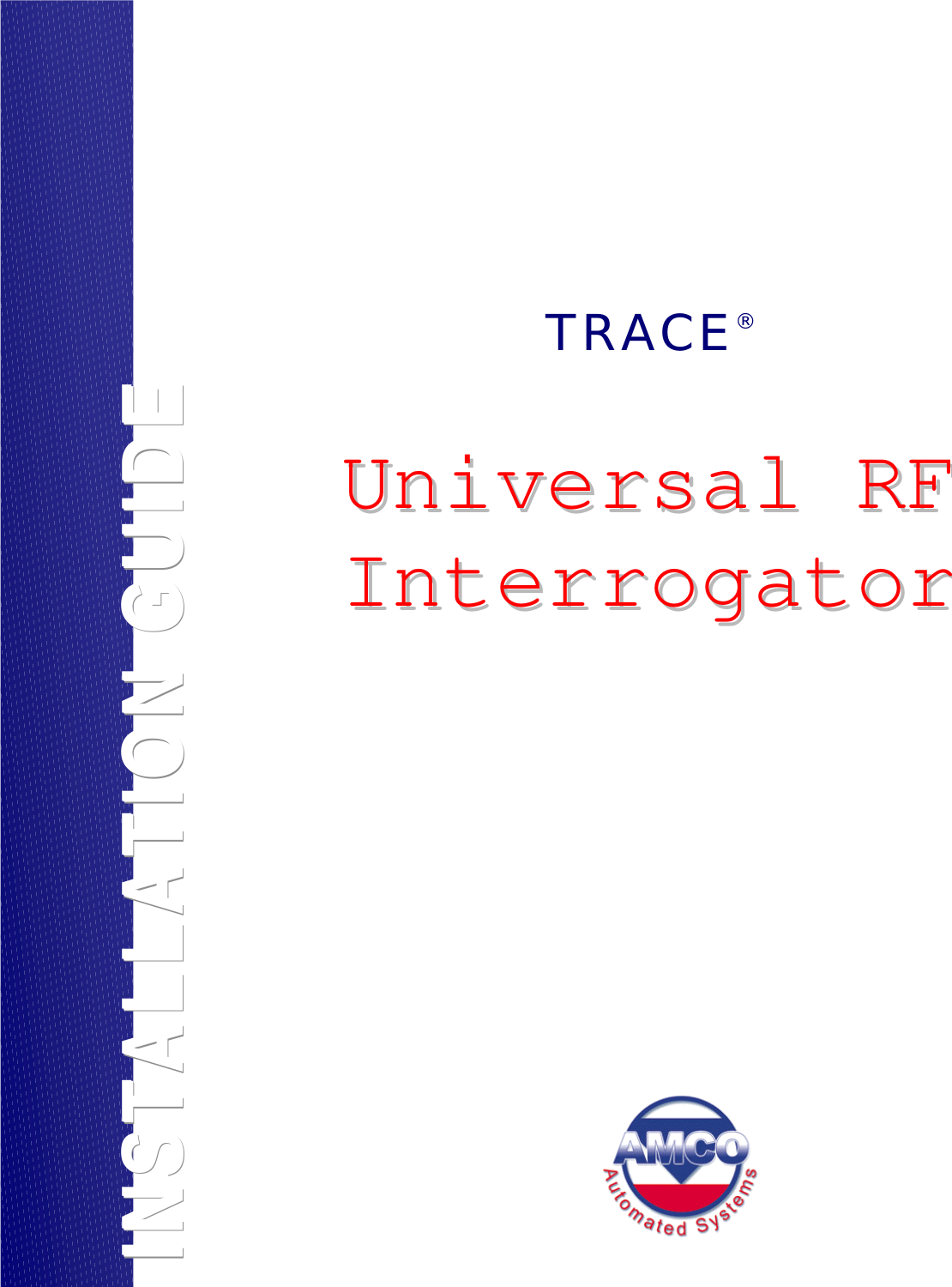
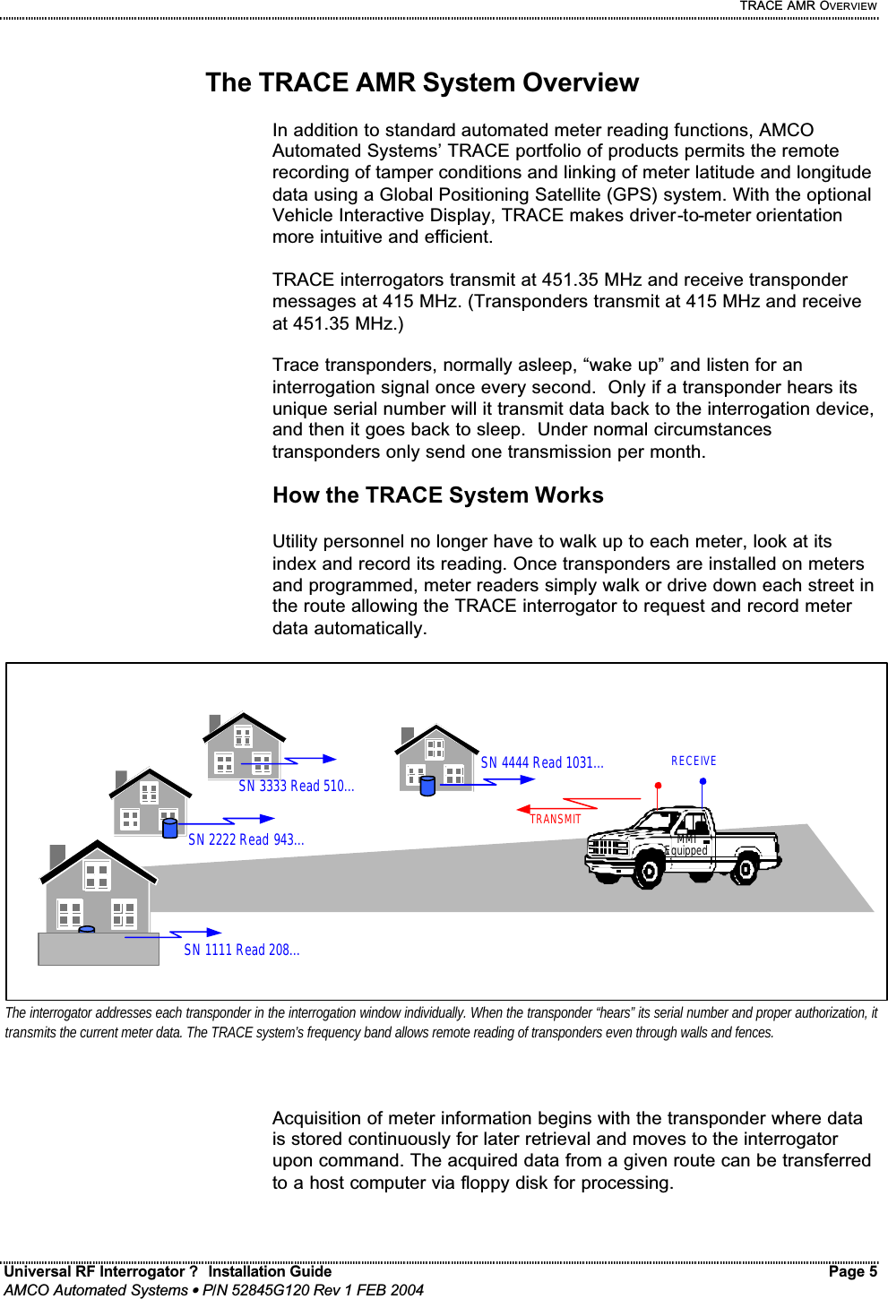
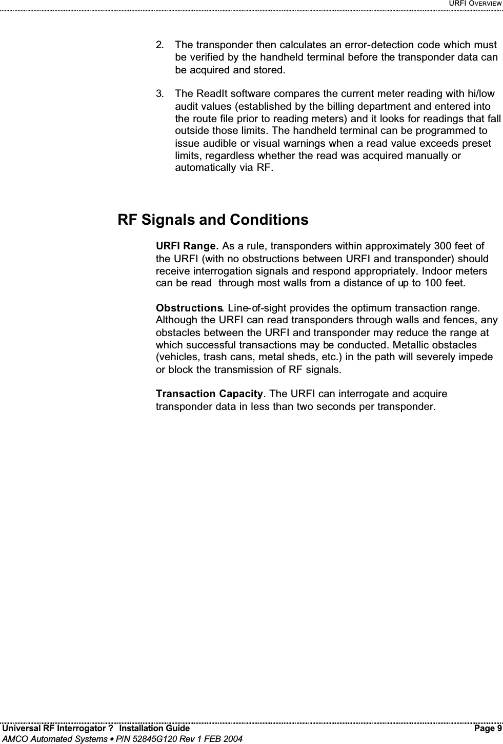
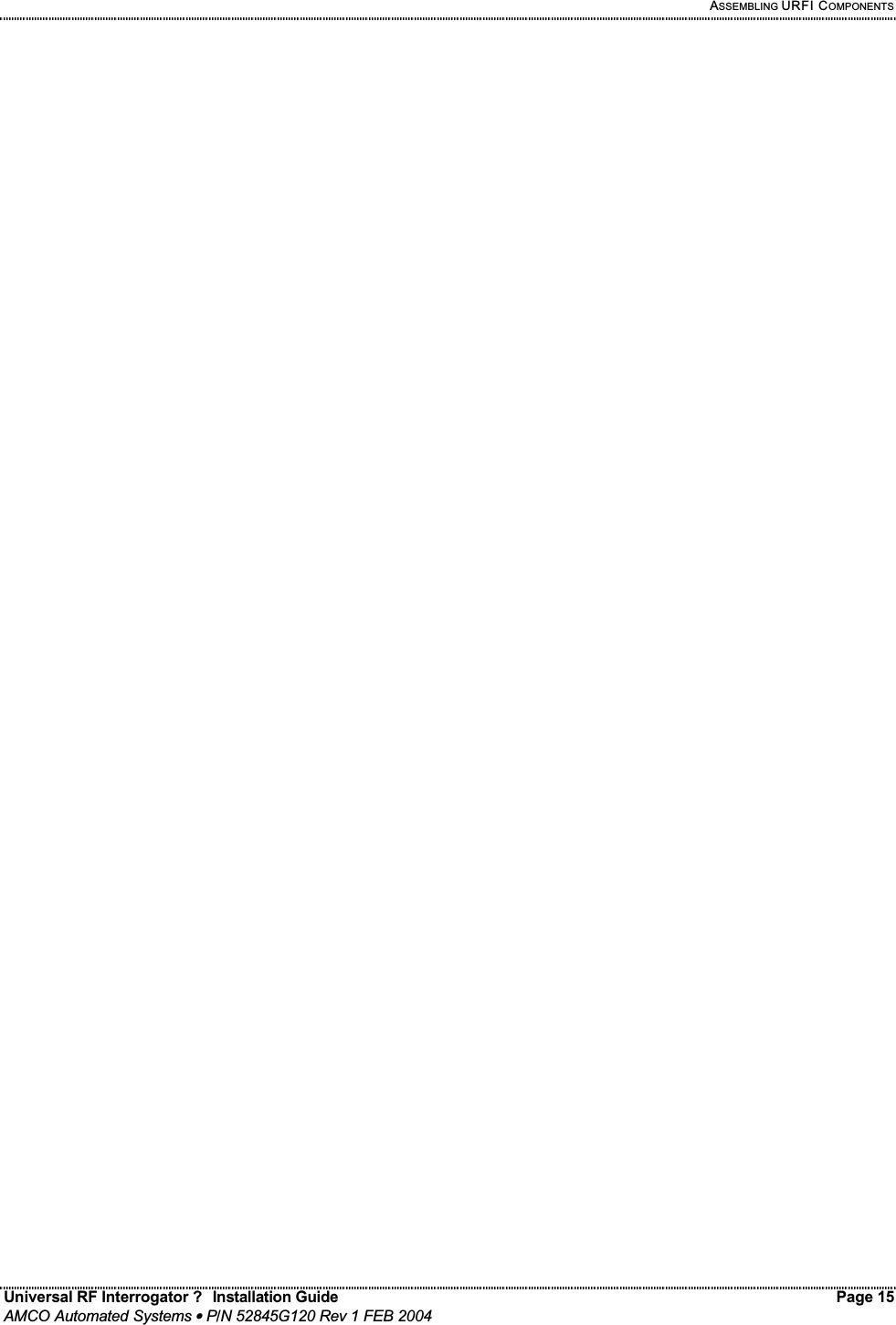
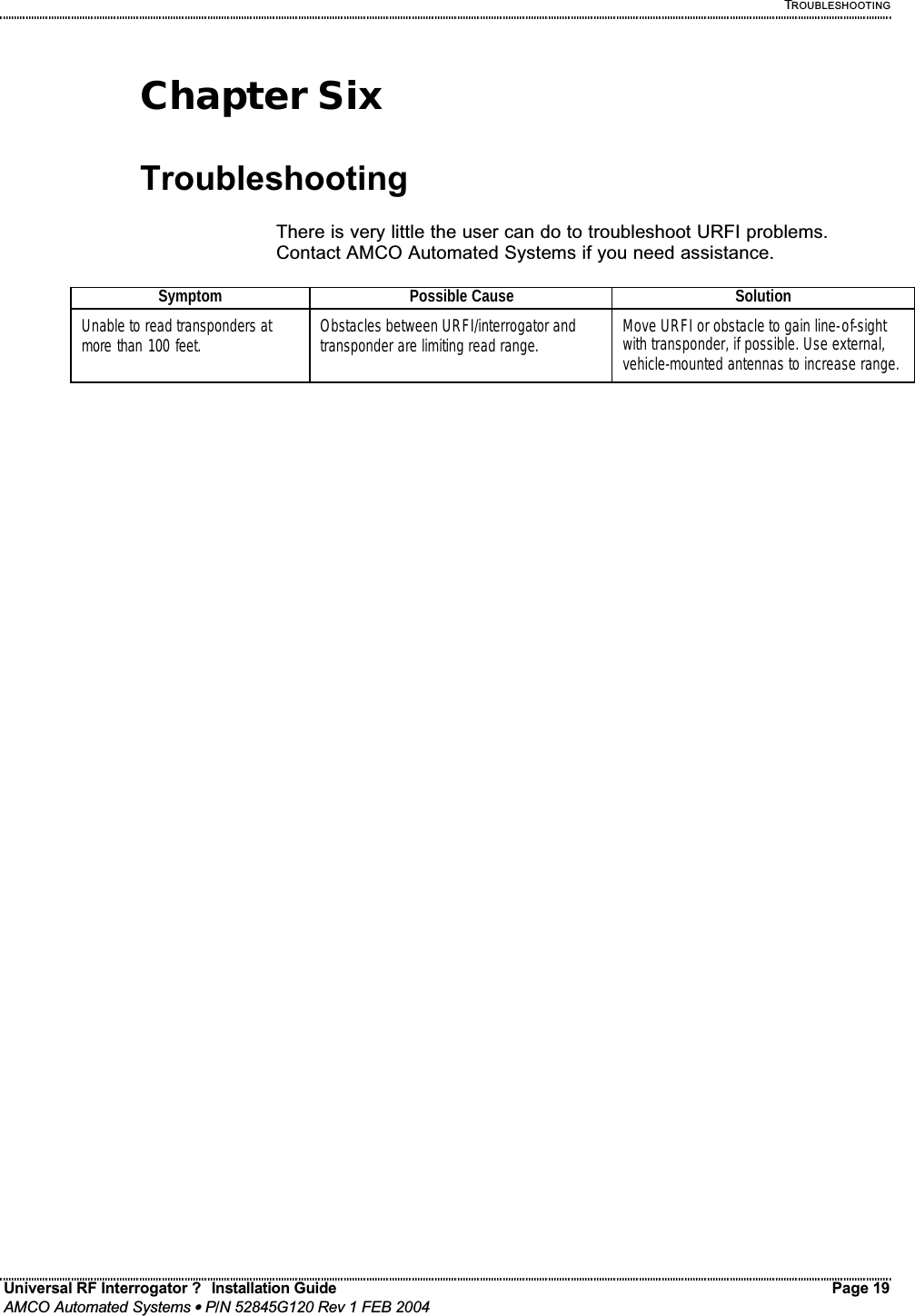
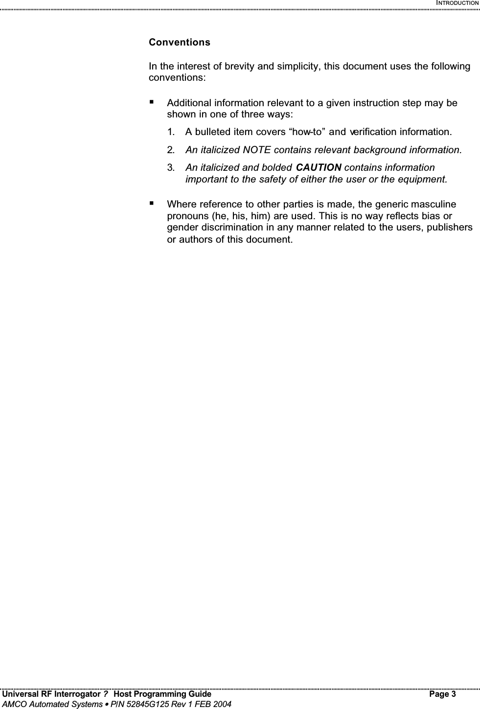
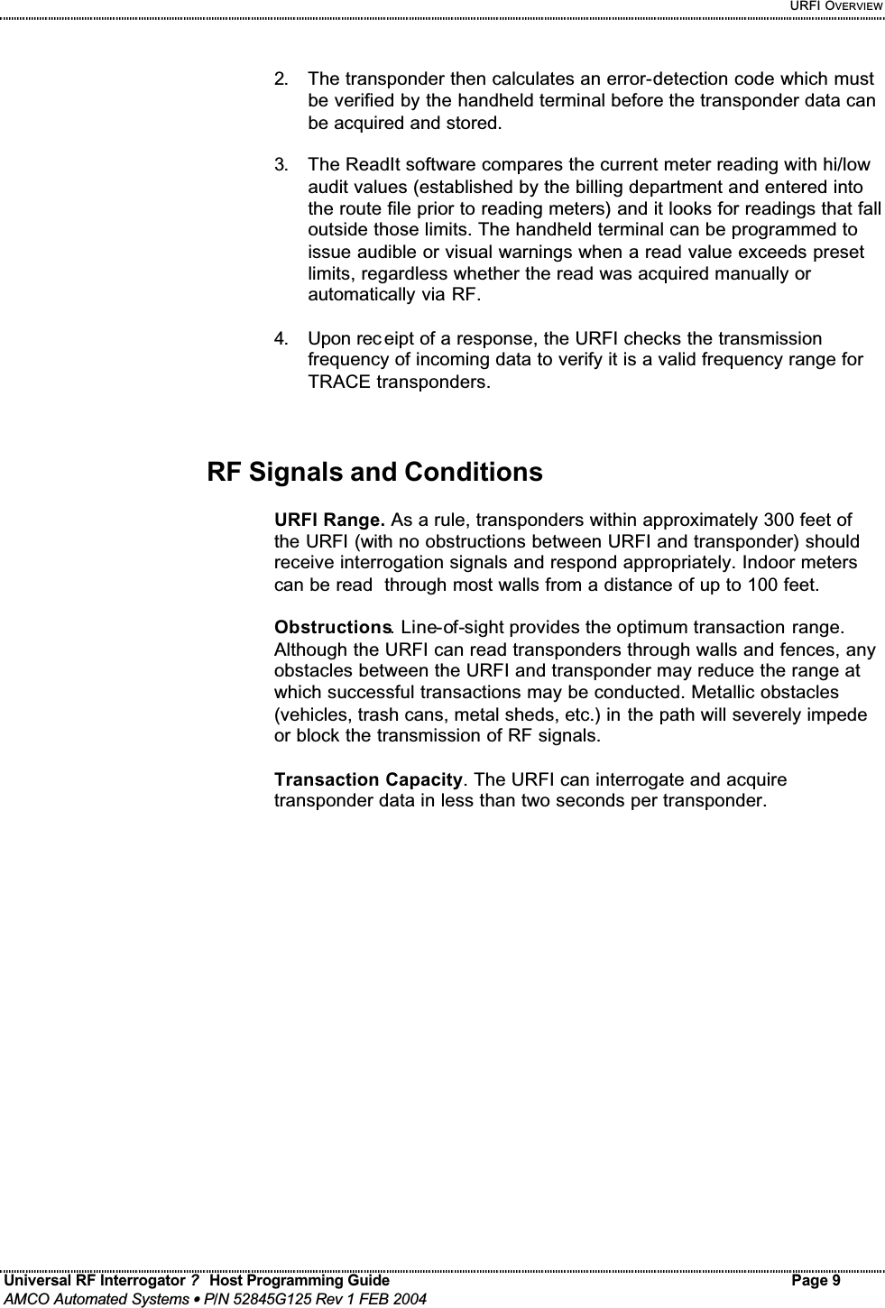
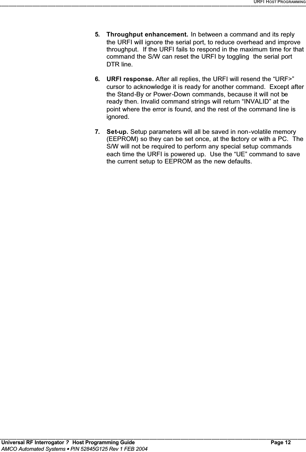
![URFI HOST PROGRAMMING Universal RF Interrogator ? Host Programming Guide Page 14 AMCO Automated Systems • P/N 52845G125 Rev 1 FEB 2004 URFI Commands The following tables detail the URFI commands and responses. Purpose Command Response Power-Up {DTR (Pin 4)=logic1} {CTS (Pin 8)=logic1} URF> (~ 0.25 sec) Power-Down {DTR line=logic0} {CTS=logic0} Stand-By SB {ignore all commands except WU[<id>]<cr>} Wake-Up WU[<id>] <id><cr><lf>URF> Where: <id> is the 5 digit Serial Number of the URFI. If none is supplied any unit will respond. Check-Summing CS<+|-> {no reply, enable or disable checksums} Update EEPROM UE {no reply, save current options as defaults} The nn last used in SPnn, SOnn, and G+,nn and F1 and F2become the power-up defaults. Read Meter RM[<sn>][,T][,F<1|2>] <Reading>[,T<S|O|B>][,C<S|R|B>],<ss>,<bat> or R<N|B|C<ch>|A|J> Where: T = Send Clear Tamper with command. (if no <sn> use previous <sn>) F1 or F2 = use Frequency 1 or 2 (if no F use F1 at power on then last one sent) T = Tamper followed by either S = Short, O = Open or B = Both. C = Corrupted followed by S = Serial Number, R = Reading, or B = Both. <ss> = The received Signal Strength (>1.0v is usually good but 2.5 is a glitch) <bat> = Battery voltage during the Interrogation. ( 9 Volts =to low to transmitt) Or if no valid reading could be found, one of the following error messages will be sent: R = Reply: N = None (no data lock), B = Bad (bad BCH), A = Aborted (batt<9V or Tx>4W) RC<ch> =Data lock found on Channel <ch> (but not on the current channel), where: <ch> =-25 to +15 (0=415 MHz in 100KHz steps) (see LC command) (NOTE: only time to scan the current RcvCh+/-10 Channels) RJ = Receiver Jammed, data lock found before interrogation started, read aborted. Read SN RS[<sn>][,T][,F<1|2>] <8 SN digits>,V<ver>,<type>,<ss>,<bat> or R<N|B|C<ch>|A|J> Where: If no <sn> uses the last SN or “?” is assumed. The other items are the same as in RM. <ver> = one digit F/W version. <type> = G for Gas, W for Water or E for Electric meter <ss> = Signal Strength <bat> =Battery voltage during transmit. R = Reply: N = None, B = Bad, C<ch> = try Channel <ch>, A = Aborted, J = Jammed.](https://usermanual.wiki/Elster-Solutions/URF01.Manual/User-Guide-400681-Page-38.png)
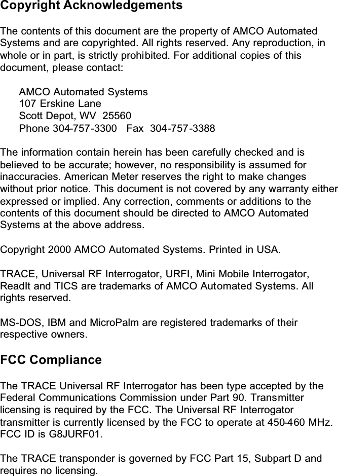
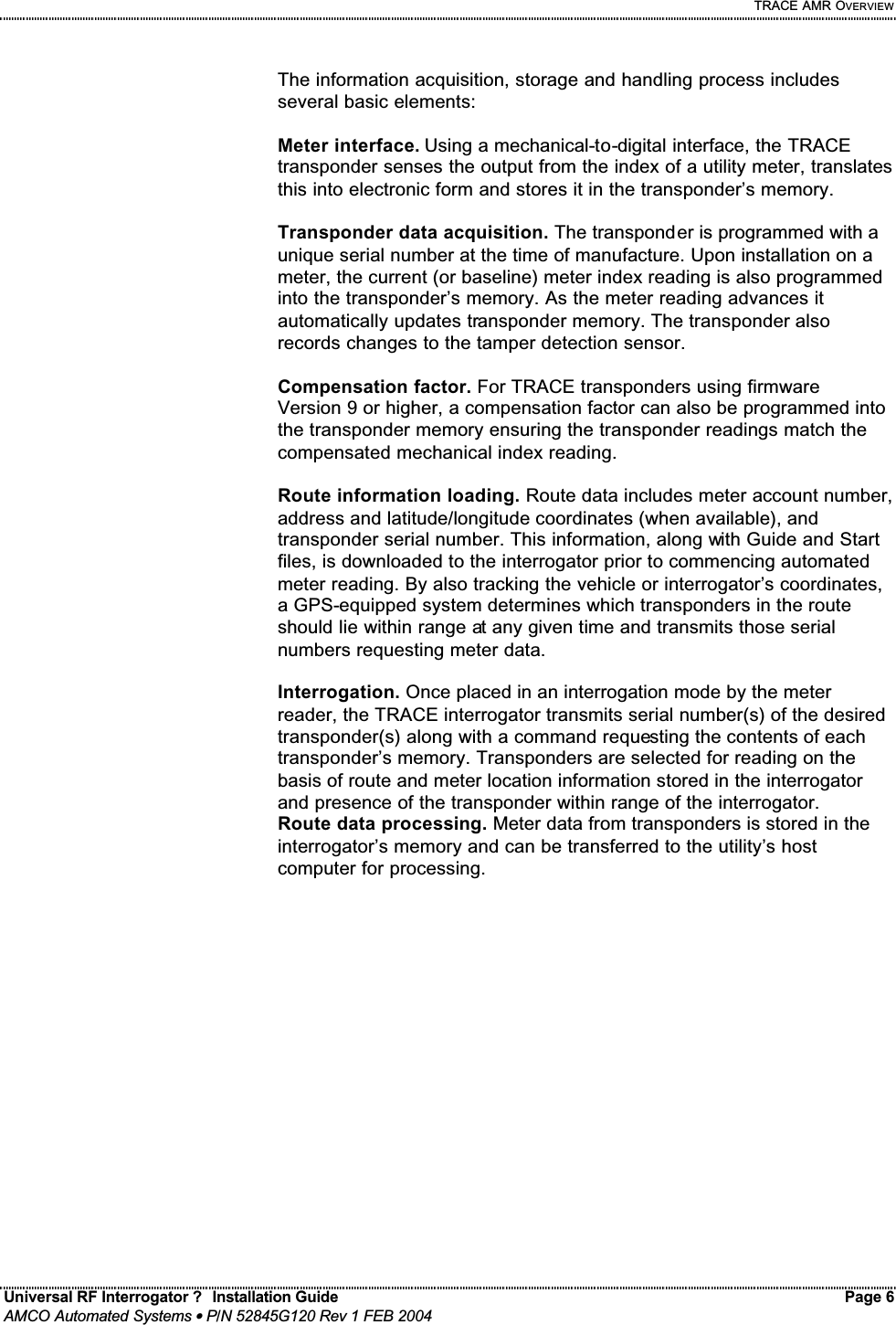
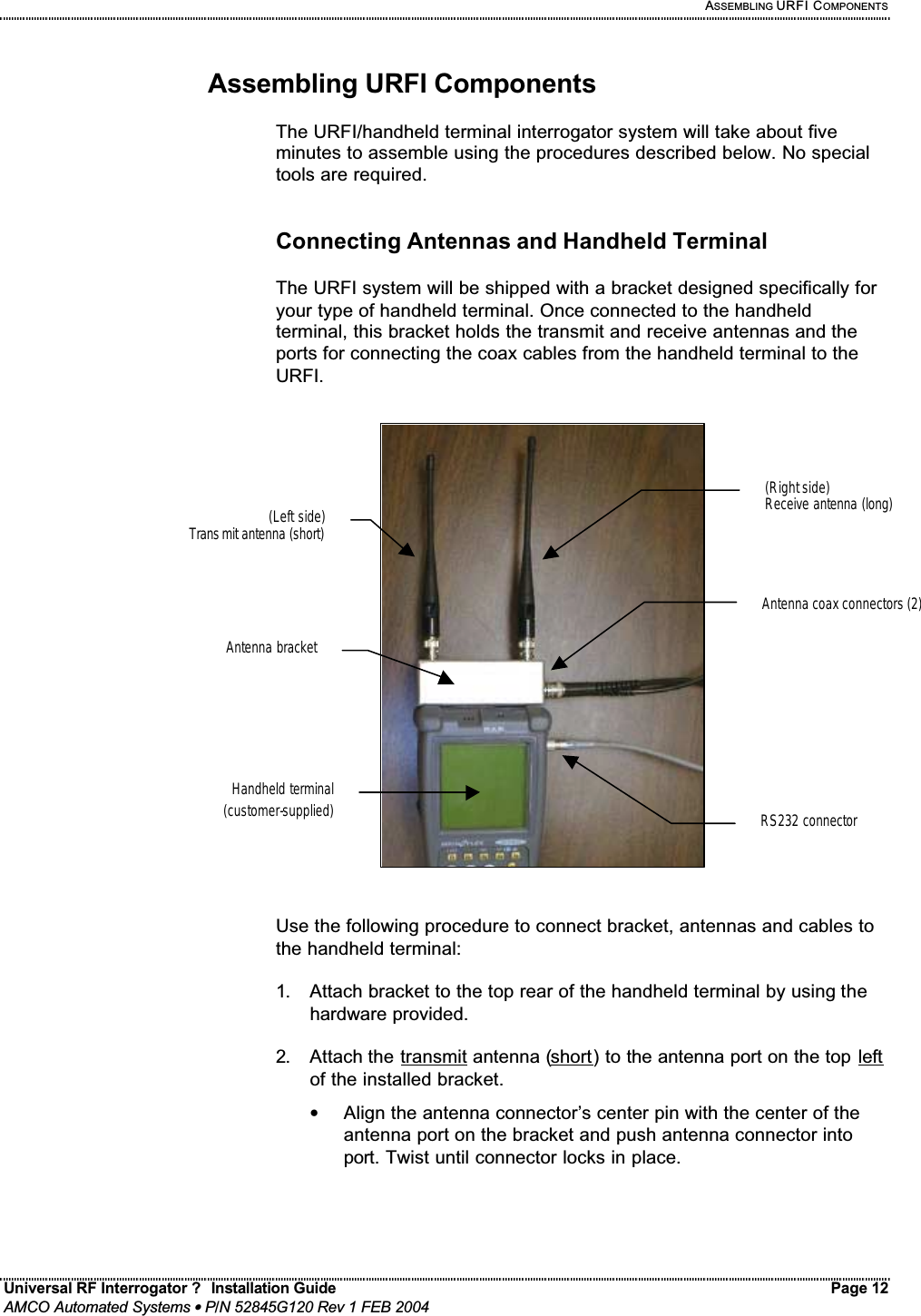
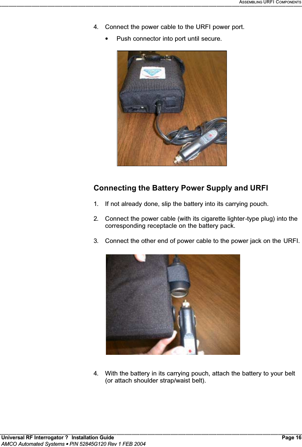
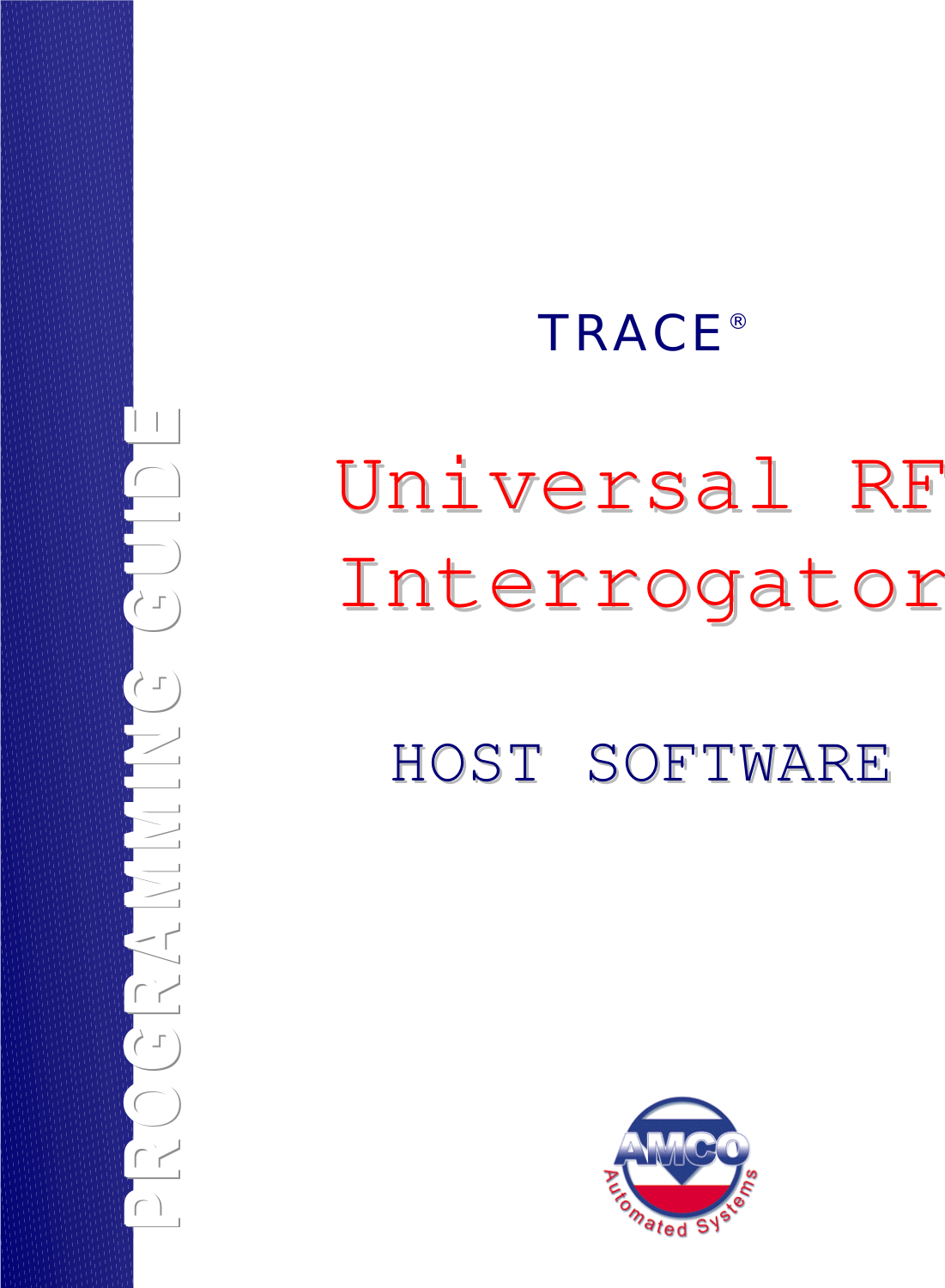
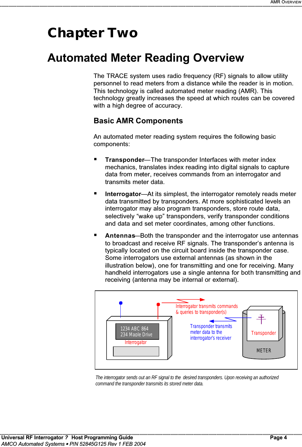
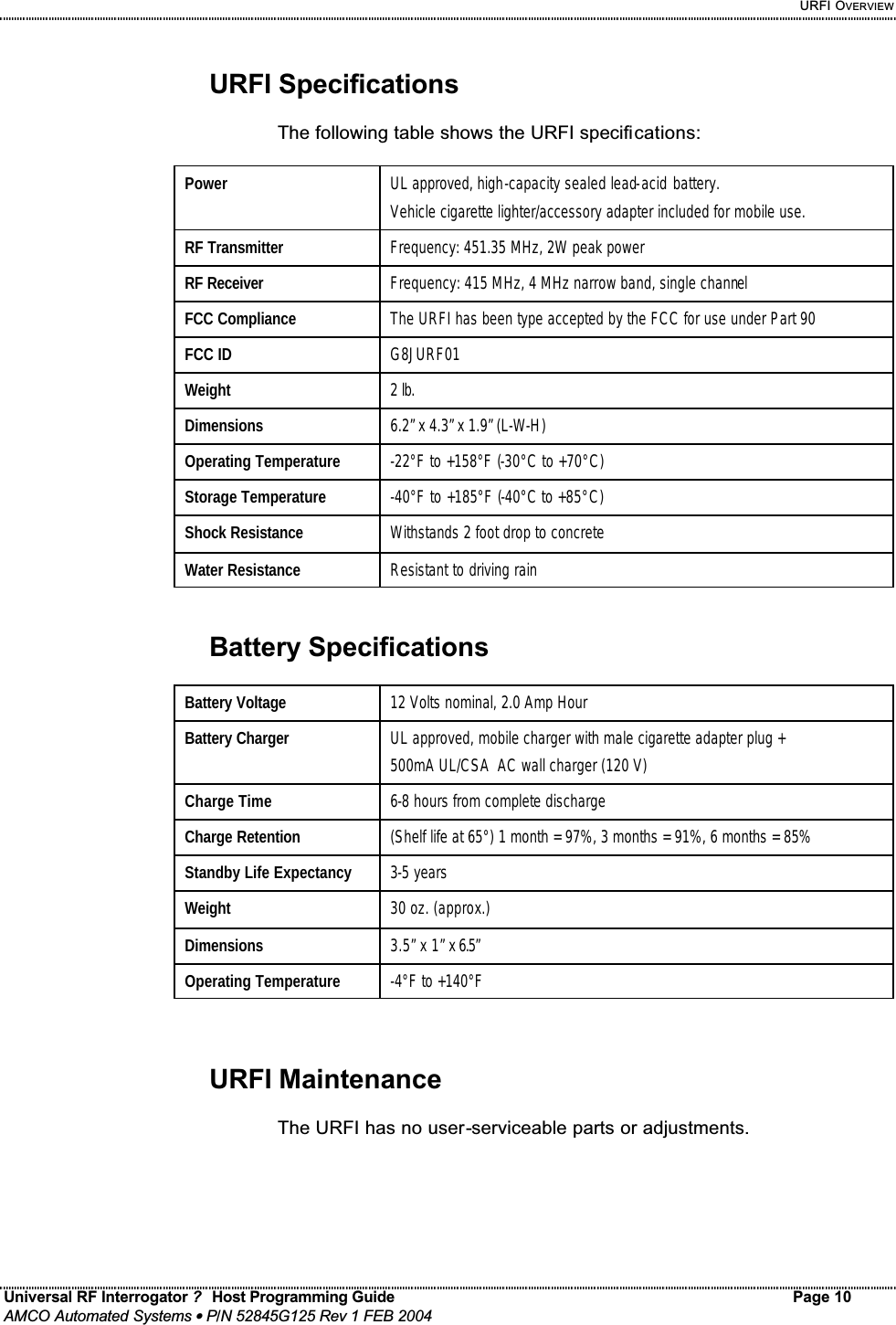
![URFI HOST PROGRAMMING Universal RF Interrogator ? Host Programming Guide Page 15 AMCO Automated Systems • P/N 52845G125 Rev 1 FEB 2004 Purpose Command Response Read Sub-Counts & P.C.F. RC[<sn>][,T][,F<1|2>] <count>/<divisor>,[<Num>/<Denom>,]<ss>,<bat> or R<N|B|C<ch>|A|J> Where: Count and divisor are 3 digit numbers, representing the fractional reading not counted yet. On Transponders with V9 code or later the Num/Denom is the Pressure Compensation Factor (P.C.F.) (default: 1/1, see PC). R = Reply: N= None, B = Bad, C<ch>= Try Channel <ch>, A= Aborted, J= Jammed. Note: This command is not valid for Gen2 (<sn> < 2,500,000). Program Compensation Factor PC[<sn>][,F<1|2>],<Num>[,|/]<Denom> [RA] {use RC command to verify} Where: RA = Programming Aborted. NOTE: Valid only for units with V9 code or later. Use RC or RS command to verify type and programming. PC can be any fraction where Num and Denom are integers from 1 to 255. By default it is 1/1 and on units before V9 the RC command will not show any factors. Program Reading PR[<sn>][,F<1|2>][, <count>] [RA] {use RM command to verify} Where: RA = Programming Aborted. Note1: If <sn> is Gen2 the S/W must prompt the user to use and remove the Programming Stick, before verifying the reading with an RM command. (RM won’t work if the Stick is still on) Note2: wild cards are not allowed when programming. If no <count>, 00000000 is assumed. Load Channel LC<ch> {none, URF>} Where <ch>=-25 to +15 (+ and leading 0 optional) Sets the Rcv frequency to that Channel Channel 0 = 415MHz and the channel spacing is 100KHz. At Power-on the default is Channel -5 (414.5MHz). When an RM, RS or RC command replies with “RC<ch>” send “LC<ch>” if you want to use this channel on the next interrogation (or to set it back to the default afterward) or record this channel in a data base for use on this SN next month. System Status SS V:<ver>,S:<csum>,B:<Volts>,I:<Volts|0.0>,C:<Rcv Ch>, T:<Xmit F1 >,<Xmit F2> Where: <ver>=URFI F/W version, <Xmit F1> and <Xmit F2> are the two licensed Transmit frequencies for this URF (defaults = 451. and 457.575 MHz). <Rcv Ch>= the last channel used, (default=-5) B<volts> is the batteries current voltage and I<volts> is the voltage during the previous Interrogation (or 0.0 if the URFI has not transmitted yet). Note: More information is displayed when the Expanded mode, “X+”, is active. (see COM2 spec.)](https://usermanual.wiki/Elster-Solutions/URF01.Manual/User-Guide-400681-Page-39.png)
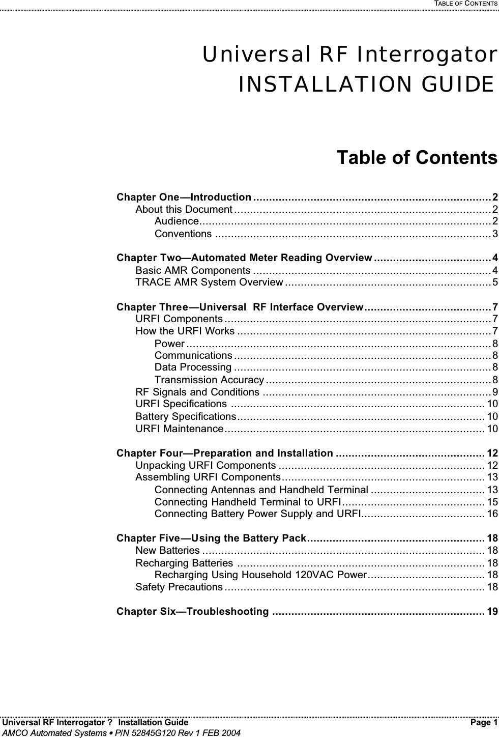
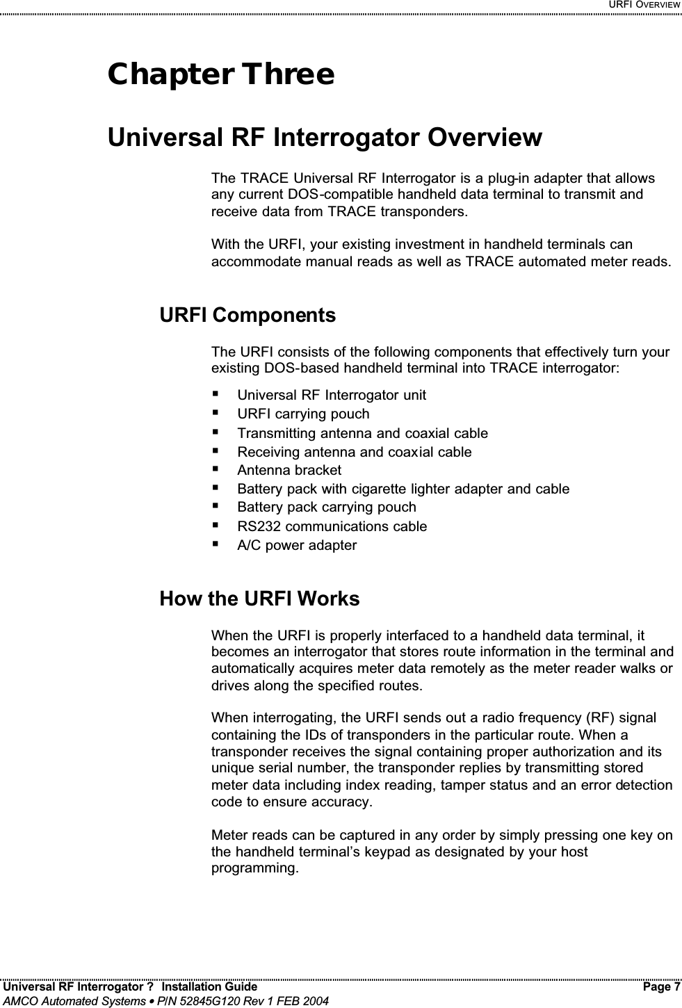
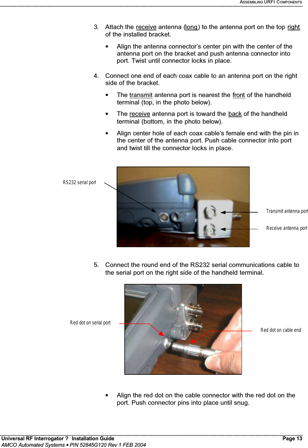
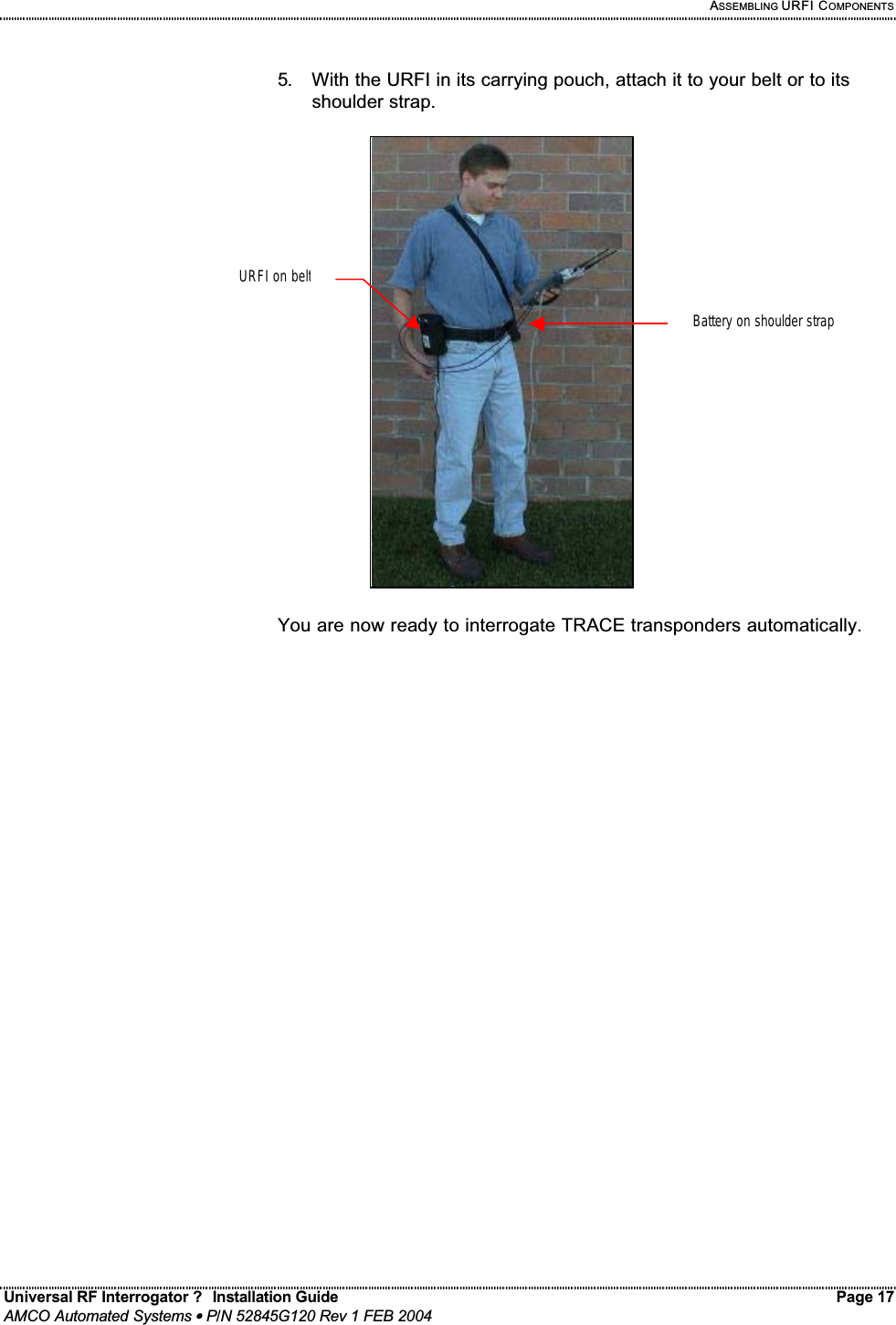
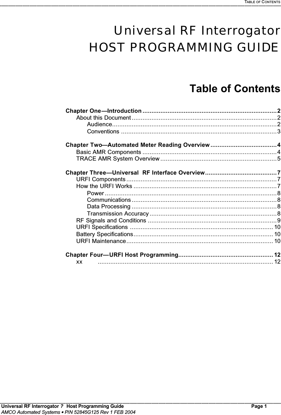
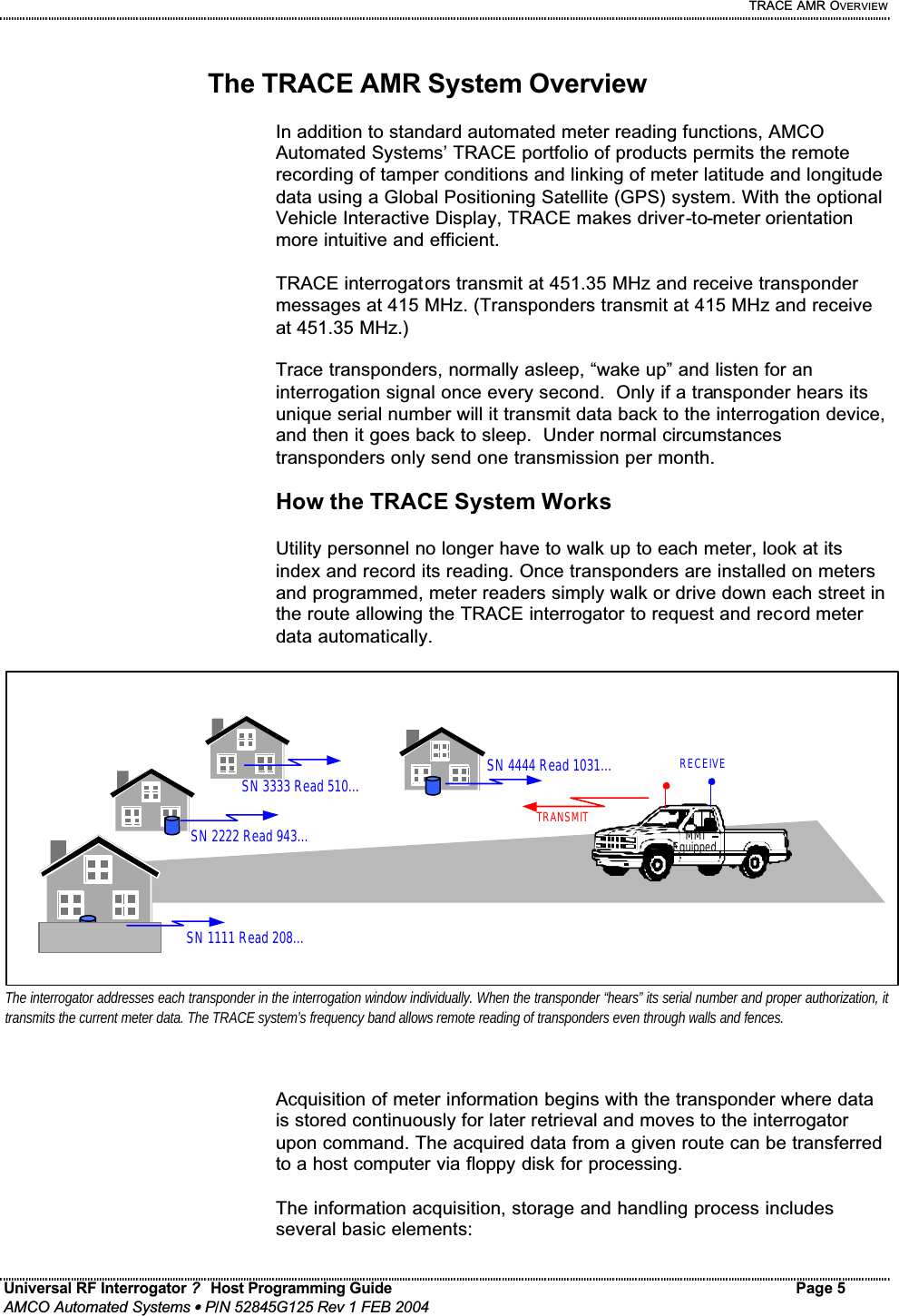
![URFI HOST PROGRAMMING Universal RF Interrogator ? Host Programming Guide Page 16 AMCO Automated Systems • P/N 52845G125 Rev 1 FEB 2004 Purpose Command Response Group Mode G<+|->[,nn] [GA] Where: G- = Normal Interrogation mode, 1.5 seconds of Dummies before each command. G+ = run the transmitter continuously , sending Dummy Ints. between commands. About 15 times faster, when conditions permit. (60 dummies before first Int. only) nn = G+ mode Time-out (in seconds), reverts back to G- mode (default=30 sec.) GA= Group mode Aborted, if Vbat<9V or Vcc<5V or TxPwr>~3W, and stops the Tx. The G+ command will wait for 5 Dummies before returning. During this time it monitors the battery, Vcc and TxPwr and returns GA if they are out of range. These items are also tested once a second when G+ is active, but no message is sent if the Tx is aborted, but the next G+ will repeat these tests and will return GA if the condition still exits. WARNING: “G+,00” will leave the transmitter on forever, but can overheat the URFI if it is not well ventilated, and will drain a battery in about 30 minutes, so use with care. The G+ command would be sent before the first SN in a group of meters known to be close together (such as in an apartment building or a new shipment of meters on the loading dock). Then the transmitter will be left on between commands, to keep all of the transponders awake, until the G- command is sent after the last SN in the group. This will allow the whole group to be read in a fraction of the normal time. In applications where battery life is not a concern the Group interrogate mode could be used all the time, to achieve near Van-like reading rates, but a G+ should still be sent again periodically to verify proper operation. Group mode is only possible when the URF is using antennas more than 3 feet apart or all transponders in the group are within 10 feet, with the supplied antennas. Antenna-switch A<E|I> Set the Antenna switch to External or Internal. (old MURFI only)](https://usermanual.wiki/Elster-Solutions/URF01.Manual/User-Guide-400681-Page-40.png)