Elster Solutions VRT03 Pit Water Meter Transponder User Manual CERTIFICATE OF COMPLIANCE
Elster Solutions, LLC Pit Water Meter Transponder CERTIFICATE OF COMPLIANCE
UserManual.wiki
>
Elster Solutions
>
VRT03 User Manual
Users Manual
Navigation menu
Upload a User Manual
Namespaces
Wiki Guide
HTML
PDF
Info
Views
User Manual
Discussion / Help
Navigation
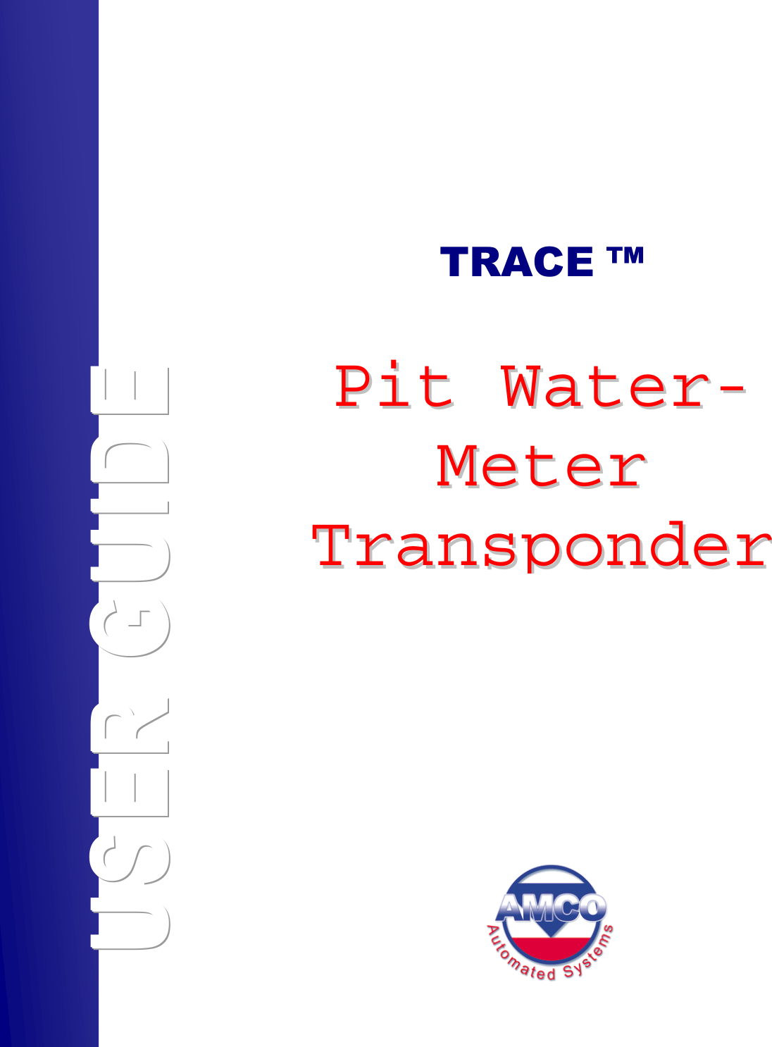
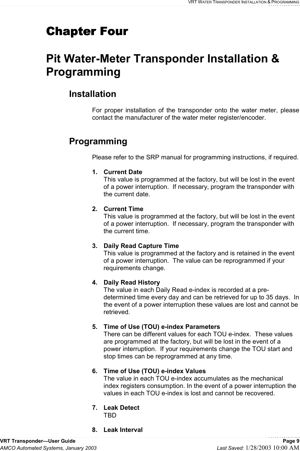
![VRT WATER TRANSPONDER INSTALLATION & PROGRAMMING VRT Transponder—User Guide Page 10 AMCO Automated Systems, January 2003 Last Saved: 1/28/2003 10:00 AM TBD 9. Leak Consumption TBD 10. Meter Type TBD 11. Next Daylight Saving Time Day Number The transponder’s internal clock will automatically switch to daylight saving time on the date represented by the value entered into this field. The value must represent a future date. Please refer to table [TABLE 01] for a list of valid entries. This value is programmed at the factory for the next valid date after it is shipped, but must be updated by the utility for subsequent periods. In the event of a power interruption the value is retained. 12. Next Standard Time Number The transponder’s internal clock will automatically switch to standard time on the date represented by the value entered into this field. The value must represent a future date. Please refer to table [TABLE 01] for a list of valid entries. This value is programmed at the factory for the next valid date after it is shipped, but must be updated by the utility for subsequent periods. In the event of a power interruption the value is retained.](https://usermanual.wiki/Elster-Solutions/VRT03/User-Guide-308388-Page-14.png)