Elster Solutions WWIC-G01 EA_Gatekeeper with Wireless WIC User Manual IL42 4036
Elster Solutions, LLC EA_Gatekeeper with Wireless WIC IL42 4036
User Guide
May 2011 IL42-4036B
Elster
Raleigh, North Carolina USA
+1 800 338 5251 (US toll free)
+1 905 634 4895 (Canada)
support@us.elster.com
A3 ALPHA® meter with
wireless cellular communication option
General
This leaflet provides general information for the Wireless WIC communication option for the A3 ALPHA meter. For
information on installing the A3 ALPHA meter, see the “ALPHA Meter Installation Instructions” (IL42-4001Q or later).
The A3 ALPHA meter may be ordered with a wireless cellular communication option: the Wireless WAN Interface Card
(Wireless WIC). The Wireless WIC is available in CDMA 1xRTT and GSM GPRS versions, providing a high speed cellular
communication channel for the meter. Additional hardware configurations may include either a relay option board or an
interrupter control board for standard ALPHA meters, or an EA_Gatekeeper module to communicate with the EnergyAxis
LAN
The A3 ALPHA meter with Wireless WIC communication may be ordered in the following configurations:
WARNING
!
Use authorized utility procedures to install and service metering equipment. Dangerous voltages are present. Equipment
damage, personal injury, or death can result if safety precautions are not followed.
Use circuit closing devices on current transformer secondaries (3S, 4S, 5S, 5A, 6S, 6A, 8S, 9S, 10S, 10A, 26S, 29S, 35S, 36S,
and 36A meters). Equipment damage, personal injury, or death can result if circuit closing secondaries are not used.
Description Model number
A3 ALPHA meter, CDMA 1xRTT, internal WAN antenna
Additional options: relay option board or interrupter control
board
A3WWIC_C
A3 ALPHA meter, CDMA 1xRTT, external WAN antenna
Additional options: relay option board or interrupter control
board
A3WWIC_CX
A3 ALPHA meter, GSM GPRS, external WAN antenna
Additional options: relay option board or interrupter control
board
A3WWIC_GX
A3 ALPHA meter with gatekeeper module, CDMA 1xRTT,
internal WAN antenna, internal LAN antenna
EA_GKWWIC_C
A3 ALPHA meter with gatekeeper module, CDMA 1xRTT,
external WAN antenna, internal LAN antenna
EA_GKWWIC_CX
A3 meter with Gatekeeper module, GSM GPRS, external WAN
antenna, internal LAN antenna
EA_GKWWIC_GX
IL42-4036B

IL42-4036B May 2011
2
Location of antennas
See Figure 1 for the location of the Wireless WIC internal antenna. If the A3 ALPHA meter is serving as an EA_Gatekeeper,
then the A3 ALPHA meter has two antennas: the Wireless WIC internal antenna is in the upper position and the EA_LAN
internal antenna is in the lower position.
The Wireless WIC internal antenna and the EA_LAN antenna (if present) are fix-mounted to the periphery of the A3 ALPHA
meter’s electronic housing. The Wireless WIC antenna and the EA_LAN antenna (if present) are not adjustable or
removable.
Alternatively, A3 ALPHA meters may be ordered with an external WIC antenna. With this option, the meter is shipped with
an RF “pigtail” output cable which allows connection to a dual-band cellular antenna external to the meter. This is
advantageous in locations with lower cellular signal strength. Also, certain Wireless WIC configurations (for example, GSM
GPRS) are presently only available with an external WIC antenna.
See Figure 2 for the recommended location of the Wireless WIC external antenna. Elster recommends mounting the
external Wireless WIC cellular antenna on the top of the meter socket box as shown, centered in the available space on the
meter box’s top surface.
■Drill and/or punch the specified antenna mounting hole in the top of the meter socket box and install the antenna
using the antenna manufacturer’s instructions.
■Connect the meter's RF “pigtail” output cable directly to the antenna via its integral N-type connector. The Wireless
WIC antenna output cable may be ordered in two lengths: 19 or 36 inches. Choose the length based on the
distance from the meter to the Wireless WIC external antenna, which is in turn determined by the size of the meter
socket box.
NOTICE
Please note that external cellular antennas must be purchased separately, either from Elster or a third party, from a list of
approved antennas. Please ask your Elster Sales Representative for the current list of approved external cellular antennas.
WARNING
!
Use approved utility safety procedures while installing the external antenna and meter RF output cable in the meter socket
box. Dangerous voltages may be present. Assure that there is sufficient clearance between any line-energized socket part
and the exposed metal of the antenna connectors. Also assure that the external antenna is electrically bonded to the
meter socket box. Failing to follow approved utility safety procedures, failing to allow sufficient clearance, or failing to
electrically bond the external antenna to the meter socket box may result in equipment damage, personal injury, or death.
May 2011 IL42-4036B
3
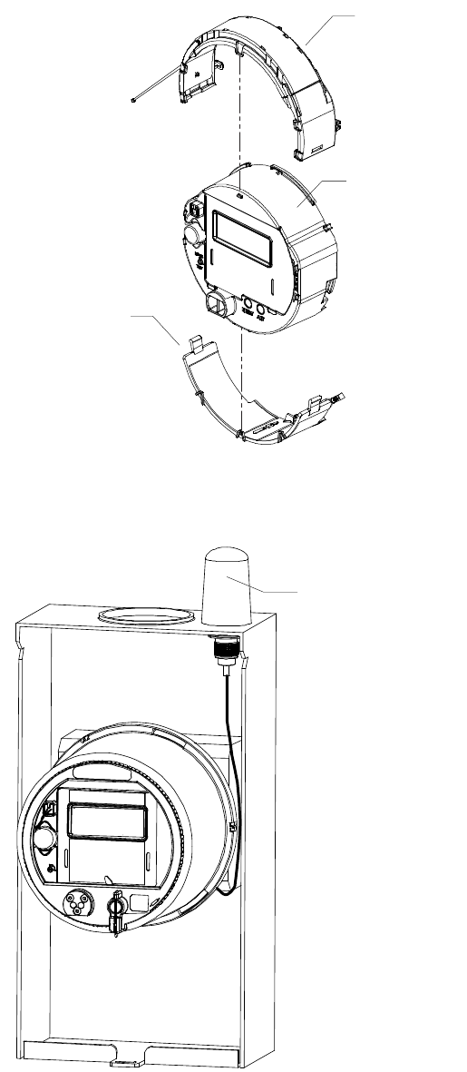
Figure 1. Location of internal antennas
Figure 2. Location of the Wireless WIC external antenna
Wireless WIC internal
antenna
Internal antenna for
connection to the EA_LAN
Electronic housing of
the A3 ALPHA meter
(Present only when serving
as an EA_Gatekeeper)
Wireless WIC external antenna
IL42-4036B May 2011
4
Placing the A3 ALPHA meter with Wireless WIC into service
WARNING
!
Use authorized utility procedures when placing the standard A3 ALPHA meter or the A3 ALPHA meter with EA_Gatekeeper
module into service. Equipment damage, personal injury, or death can result if authorized utility procedures are not
followed.
See IL42-4001Q or later for the A3 ALPHA meter installation instructions. When planning the meter installation, consider the
following additional guidelines:
■Since the Wireless WIC and EA_LAN (if present) are high frequency communication devices, site the meter so that
the front of the meter has the best possible view of the surrounding terrain.
■Do not place metal structures (other than the meter socket and related cabling) within 20 cm of the meter.
After the Wireless WIC external antenna is installed (if supplied) and the A3 ALPHA meter is installed and powered as
instructed in IL42-4001Q or later, the installation is complete. To verify operation of the Wireless WIC on-site, the following
steps may be taken:
1. After installing and powering the A3 ALPHA meter, wait approximately 5 minutes for the Wireless WIC to connect to
the cellular network and initialize.
2. Using Metercat and an optical probe connection, perform a diagnostic read. For information on using Metercat
and performing diagnostic reads, see the Metercat software documentation or online Help.
3. Once the diagnostic read is performed, select the Special Option Board section. Several operational parameters
are provided, including the following:
Item Expected status
WAN Wireless Status
Status "Connected" means the Wireless WIC is registered to the cellular network
Received Signal Strength
Indication (RSSI)
The RSSI may vary between 0 and 31, with 31 indicating the best possible signal
strength. An RSSI value of 99 indicates an unknown or non-detectable signal.
WAN IP address The IP address provided by the cellular network.
May 2011 IL42-4036B
5
FCC Compliance
Important
The A3 ALPHA meter equipped with the Wireless WIC option complies with Part 15 of the FCC Rules. Changes or modifications not expressly approved
by Elster could void the user's authority to operate the equipment.
FCC & IC Information
For CDMA 1xRTT versions of the A3 ALPHA meter with the EA_Gatekeeper module and the Wireless WIC option:
• FCC ID: QZCWWIC-C01
• IC: 4557A-WWICC01
For GSM GPRS version of the A3 ALPHA meter with the EA_Gatekeeper module and Wireless WIC option:
• FCC ID: QZCWWIC-G01
• IC: 4557A-WWICG01
For CDMA 1xRTT versions of the standard A3 ALPHA meter with the Wireless WIC option:
• FCC ID: O9EQ26ELITE
• IC: 3651C-Q26ELITE
For GSM GPRS versions of the standard A3 ALPHA meter with the Wireless WIC option:
• FCC ID: N7NQ2687
• IC: 2417C-Q2687
Compliance Statement
This device complies with Part 15 of the FCC Rules and Class B digital apparatus requirements for ICES-003. Operation is subject to the following two
conditions: (1) This device may not cause harmful interference, and (2) this device must accept any interference received, including interference that may
cause undesired operation of the device.
Énoncé de conformité
Cet appareil est conforme à la Partie 15 des règles de la FCC et aux exigences relatives aux appareils numériques de classe B conformément à l'avis sur la
compatibilité électromagnétique ACEM-3. L'utilisation de cet appareil est soumise aux deux conditions suivantes : (1) Cet appareil ne doit pas provoquer
d'interférences nocives et (2) cet appareil doit accepter toutes les interférences reçues notamment celles pouvant provoquer un fonctionnement intempestif
de l'appareil.
Note
This equipment has been tested and found to comply with the limits for a Class B digital device, pursuant to Part 15 of the FCC Rules and ICES-003.
These limits are designed to provide reasonable protection against harmful interference in a residential installation. This equipment generates, uses and
can radiate radio frequency energy and, if not installed and used in accordance with the instructions, may cause harmful interference to radio
communications. However, there is no guarantee that interference will not occur in a particular installation. If this equipment does cause harmful
interference to radio or television reception, which can be determined by turning the equipment off and on, the user is encouraged to try to correct the
interference by one or more of the following measures:
• reorient or relocate the receiving antenna
• increase the separation between the equipment and the receiver
• connect the equipment into an outlet on a circuit different from that to which the receiver is connected
• consult the dealer or an experienced radio/TV technician for help
If you experience trouble with this equipment, please use the Return Material Authorization (RMA) feature available from the customer support section of
www.elstersolutions.com. Do not attempt to repair this equipment yourself.
Antenna Compliance
The A3 ALPHA meter equipped with the Wireless WIC option has been tested and certified with the internal antenna(s) and external antenna(s) provided
by Elster. The internal antenna(s) must not be modified or replaced.
For all standard A3 ALPHA meter CDMA units, if the user wishes to use a different external antenna, the following constraints must be adhered to:
• 850 MHz band: The antenna system gain must not exceed 7.91 dBi gain.
• 1900 MHz PCS band: The antenna system gain must not exceed 7.01 dBi gain.
For all standard A3 ALPHA meter GSM units, if the user wishes to use a different external antenna, the following constraints must be adhered to:
• 850 MHz band: The antenna system gain must not exceed 7.93 dBi gain.
• 1900 MHz PCS band: The antenna system gain must not exceed 3.5 dBi gain.
Caution
The antennas used for these transmitters must be installed to provide a separation of at least 20 cm from all persons and must not be collocated or
operated in conjunction with any other antenna or transmitter except as documented in the FCC application. These devices have been approved for
simultaneous transmission of the collocated EA_LAN and cellular/PCS transmitters. Users and installers must be provided with antenna installation
instructions and transmitter operating conditions for satisfying RF exposure compliance.
IL42-4036B May 2011
6
Notes:
May 2011 IL42-4036B
7
Notes:

IL42-4036B May 2011
DISCLAIMER OF WARRANTIES AND LIMITATIONS OF LIABILITY
There are no understandings, agreements, representations, or warranties either express or implied, including warranties of merchantability or
fitness for a particular purpose, other than those specifically set out by any existing contract between the parties. Any such contract states the entire
obligation of the seller. The contents of this document shall not become part of or modify any prior existing agreement, commitment, or relationship.
The information, recommendations, descriptions, and safety notices in this document are based on Elster experience and judgment with respect to
operation and maintenance of the described product. This information should not be considered as all-inclusive or covering all contingencies. If
further information is required, Elster should be consulted.
No warranties, either expressed or implied, including warranties of fitness for a particular purpose or merchantability, or warranties arising from the
course of dealing or usage of trade, are made regarding the information, recommendations, descriptions, warnings, and cautions contained
herein.
In no event will Elster be responsible to the user in contract, in tort (including negligence), strict liability or otherwise for any special, indirect, incidental,
or consequential damage or loss whatsoever, including but not limited to: damage or loss of use of equipment, cost of capital, loss of profits or
revenues, or claims against the user by its customers resulting from the use of the information, recommendations, descriptions, and safety notices
contained herein.
Elster
Raleigh, North Carolina USA
*IL42-4036B*
© 2011 by Elster
All rights reserved.
Printed in the United States.
Notes: