Elster Solutions WWIC3EV Electric Meter with Multi-band CDMA and Frequency Hopping Transmitters User Manual 1
Elster Solutions, LLC Electric Meter with Multi-band CDMA and Frequency Hopping Transmitters Users Manual 1
Contents
- 1. Users Manual 1
- 2. Users Manual 2
Users Manual 1
General
This instructional leaflet contains general installation instructions for the following single phase and
polyphase watthour meters:
• socket-connected meters: 1S, 2S, 3S, 4S, 5S, 6S, 8S, 9S, 10S, 12S, 13S, 16S, 26S, 29S, 35S, 36S, 45S, 56S
• bottom-connected meters: 5A, 6A, 10A, 13A, 16A, 35A, 36A, 45A
See the following technical manuals for more information about the ALPHA meter:
•ALPHA
® Meter Technical Manual (TM42-2180A or later)
• ALPHA Meter Options Technical Manual (TM42-2181B or later)
•ALPHA Plus
® Meter Technical Manual (TM42-2182C or later)
• A3 ALPHA Meter Technical Manual (TM42-2190A or later)
All meters are calibrated and tested before shipment. For proper installation, accuracy, and maximum
life of the meters, use the following installation procedures.
Use authorized utility procedures to install and service metering equipment. Dangerous voltages are
present. Equipment damage, personal injury, or death can result if safety precautions are not
followed.
Use circuit closing devices on any current transformer secondaries (3S, 4S, 5S, 5A, 6S, 6A, 8S, 9S, 10S,
10A, 26S, 29S, 35S, 35A, 36S, and 36A meters). Equipment damage, personal injury, or death can
result if circuit closing devices are not used.
Form 45S, Form 45A, and Form 56S meters present additional risks of electrical shock that may result
in severe personal injury or death when the cover is removed from energized meters unless certain
additional safety procedures and precautions are followed. Be sure to follow the safety procedures
and precautions when servicing Form 45S, Form 45A, and Form 56S meters as stated in this manual
(see “Forms 45S, 45A, and 56S safety precautions” on page 3) as well as your authorized utility
procedures.
ALPHA meter
Installation instructions
IL42-4001S

ALPHA meter
IL42-4001S
2
Socket-connected installation
Before you install the meter, check the following:
• Are the socket and meter current class ratings compatible with the meter?
• Is the wiring to the meter socket correct? See the wiring diagrams on the following pages.
• Is a lightning arrestor present? If so, remove the paint from the socket rim where it contacts the
arrestor's ground strap. This will ensure proper grounding.
• Is the TEST button in the unlocked position? If the TEST button is in the locked position, the meter will
enter TEST mode when you install it. For more information, see the technical manual for your meter.
After you install the meter, check the following:
• If load is applied, check that the pulse arrows on the LCD are blinking.
The LCD has 2 sets of pulse arrows, one located above the other. The upper set of arrows indicates
watthours, and the lower set indicates alternate energy (kVARh or kVAh, if available). The arrows
pointing to the left indicate energy received; arrows pointing to the right indicate energy delivered.
For more information, see the technical manual for your meter.
Bottom-connected installation
Before you install a bottom-connected meter, check the following:
• Determine where the meter is to be installed. It should be on a flat wall at the point of electrical
service entrance cables.
• Are the meter class and service connections compatible with the meter?
To install a bottom-connected meter, perform these steps:
1 Mount the bottom-connected meter or the bottom-connected S-to-A adapter.1
Use authorized utility procedures to install ground connection before wiring. Dangerous voltages are
present. Equipment damage, personal injury, or death can result from wiring an ungrounded meter.
2 Wire the meter. See the wiring diagrams beginning on page 3. If the wire diagram is larger than the
wire, use only approved adapters. External meter wiring should be consistent with the meter class
rating.
- For 100 amp meters, use #2 wiring (or in accordance with standard utility operating practices)
- For 150 amp meters, use #1 AWG or 50 mm2 wiring (or in accordance with standard utility
operating practices)
- For transformer rated meters, use #9 wiring (or in accordance with standard utility operating
practices)
1Not supplied by Elster Solutions.

ALPHA meter
IL42-4001S
3
After you install a bottom-connected meter, check the following:
• If load is applied, check that the pulse arrows on the LCD are blinking.
The LCD has 2 sets of pulse arrows, one located above the other. The upper set of arrows indicates
watthours, and the lower set indicates alternate energy (kVARh or kVAh, if available). The arrows
pointing to the left indicate energy received; arrows pointing to the right indicate energy delivered.
For more information, see the technical manual for your meter.
• The TEST annunciator is not blinking. If it is blinking, then remove the meter from service, remove the
cover, and rotate the TEST button so that the meter is placed out of test mode. For more information,
see the technical manual for your meter.
Forms 45S, 45A, and 56S safety precautions
Form 45S, Form 45A, and Form 56S meters present additional risks of electrical shock that may result
in severe personal injury or death when the cover is removed from energized meters unless certain
additional safety procedures and precautions are followed. Be sure to follow the safety procedures
and precautions when servicing Form 45S, Form 45A, and Form 56S meters as stated in this manual
as well as your authorized procedures.
When using Forms 45S, 45A, and 56S meters, be sure to understand and follow the important safety-
related concerns.
• Form 45S meters: safety concerns exist with Form 45S meters in any application in which socket jaw
7 is not grounded.
• Form 45A meters: safety concerns exist with Form 45A meters in any application in which the
equivalent terminal to the Form 45S socket jaw 7 is not grounded (A-base voltage terminal #6, as
numbered from left-to-right).
• Form 56S meters: safety concerns exist with Form 56S meters in any application in which socket jaw
16 is not grounded.
These safety concerns include, but are not necessarily limited to, the following:
• 3-wire delta applications
• dual single phase “star” configurations (may also be referred to as 5-wire, 2-phase)
• 4-wire delta applications in which the high leg is not tied to phase C
The primary safety concerns in these applications are as follows:
1 The meter battery terminals and circuit board electronics will be at line potential.
2 The circuit board electronics of any installed option board will be at line potential.
3 Any internal antenna or other electrical extension of any installed option board will be at line
potential.
It is important to assess the potential hazards after removing the meter cover and disconnect the
electrical power as necessary to perform service.
ALPHA meter
IL42-4001S
4
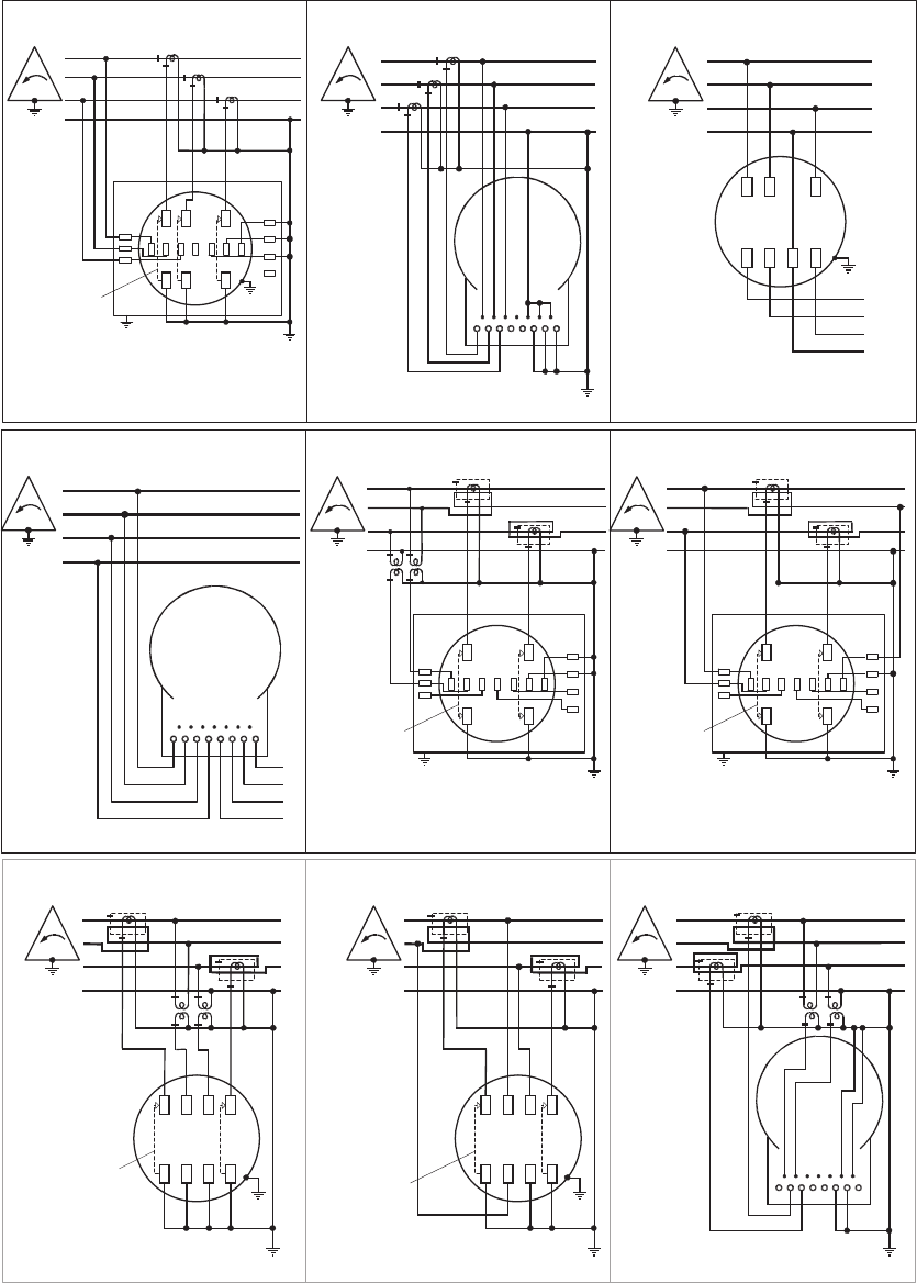
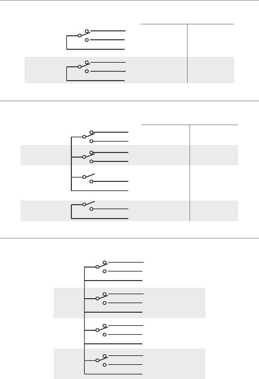
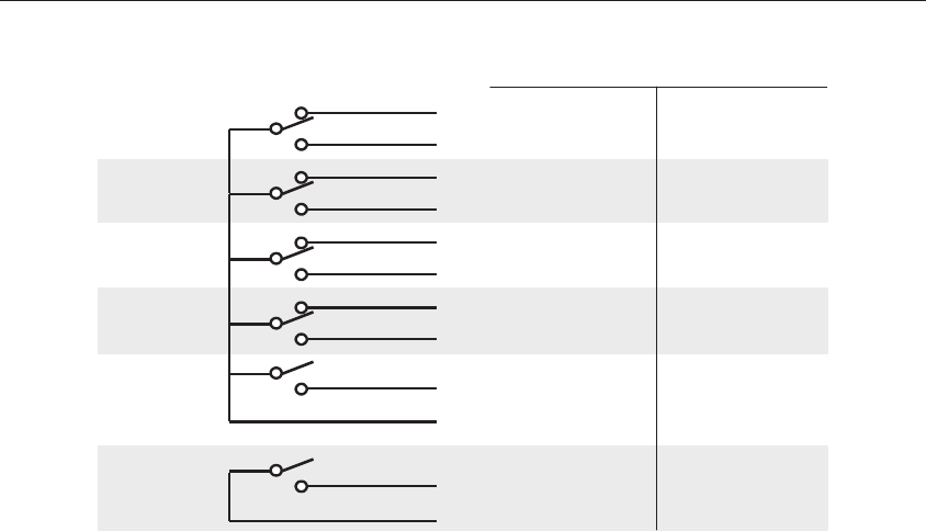
Installation wiring
All available ALPHA meter forms are listed and separated with respect to the type of service being
metered. Use of Form 9S, 10S, and 10A (in 8S and 8A applications), and Form 16S (in Form 15S
application) are also shown. Form 14S and 14A applications are simply 4 wire WYE services and would
be metered by Form 16S and 16A. The more complicated wirings are shown using both PTs and CTs.
The socket ground is shown for safety considerations. The neutral-to-ground connection is shown for
example only. Actual neutral-to-ground connection should be performed within the operating utility's
standard practice.
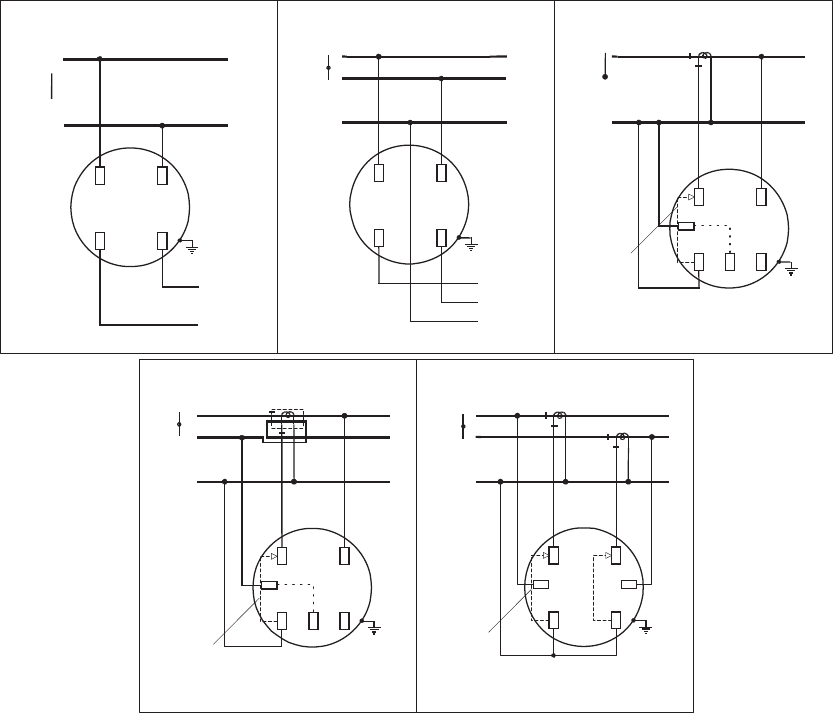
Single phase meters
N
1
L
O
A
D
1
N
1
N
Form 1S
1 phase, 2 wire, self–contained
20E01
1
2
N
L
O
A
D
2
N
1
N
2
1
Form 2S
1 phase, 3 wire, self–contained
20E01
Form 3S
1 phase, 2 wire, 1 CT, no PTs
29A02
1
N
N
1
CIRCUIT
CLOSING
DEVICE
Form 3S
1 phase, 3 wire, 1 CT, no PTs
14I01
1
2
N
N
2
1
CIRCUIT
CLOSING
DEVICE
Form 4S
1 phase, 3 wire, 2 CTs, no PTs
29A02
1
2
N
N
2
1
CIRCUIT
CLOSING
DEVICE
Reduce CT ratio by ½

ALPHA meter
IL42-4001S
5
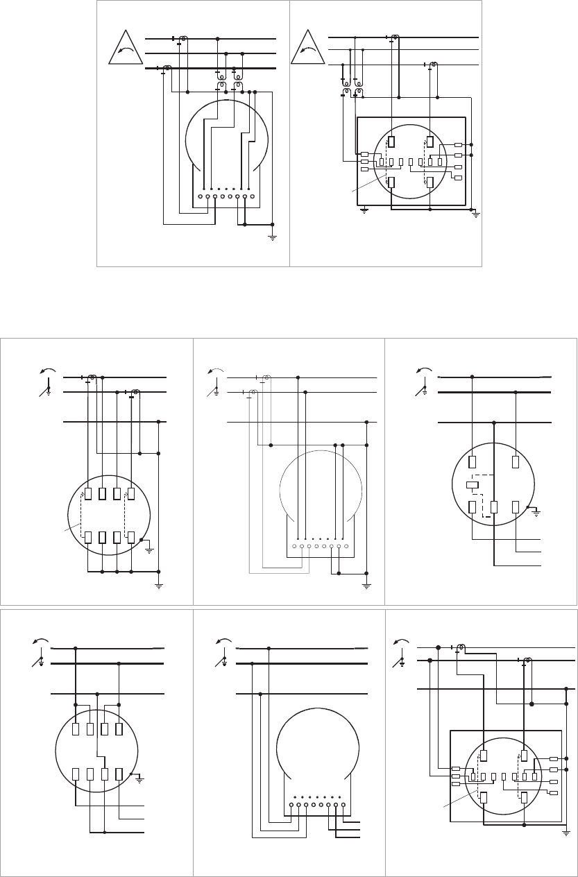
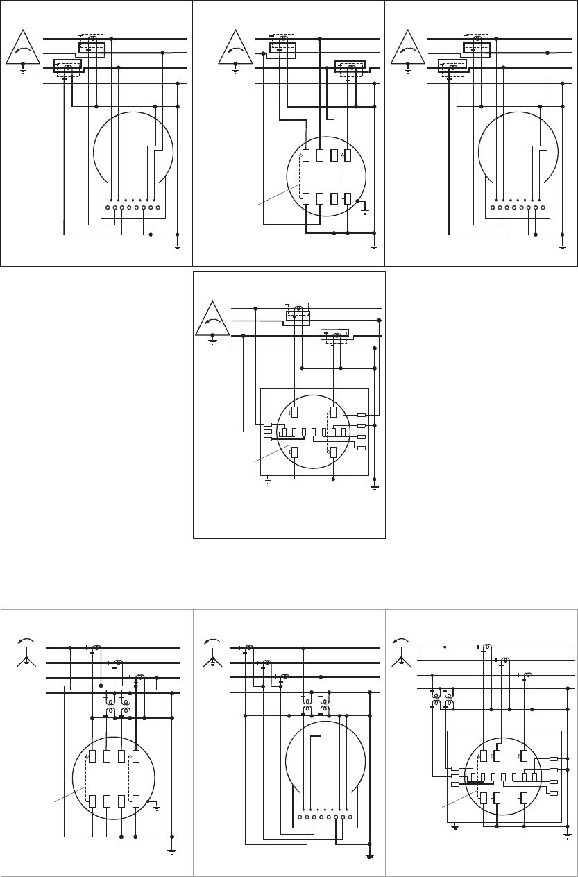
3 wire delta meters
3
21
1
2
3
Form 5A
3 phase, 3 wire delta, 2 CTs, 0 or 2 PTs
20E01
1
2
3
CIRCUIT
CLOSING
DEVICE
3
21
20E01
Form 5S
3 phase, 3 wire delta, 2 CTs, 0 or 2 PTs
1
2
3
L
O
A
D
2
1
3
3
21
Form 12S
3 phase, 3 wire delta, self–contained
20E01
Form 26S
3 phase, 3 wire delta, 2 CTs, 0 or 2 PTs
20E01
3
21
CIRCUIT
CLOSING
DEVICE
KZ
Y
1
2
3
Form 13A
3 phase, 3 wire delta, self-contained
20E01
3
21
1
2
3
L
O
A
D
1
2
3
Form 13S
3 phase, 3 wire delta, self-contained
20E01
1
2
3
L
O
A
D
2
1
3
3
21
23A06
Form 45S
3 phase, 3 wire delta, 2 CTs, 0 or 2 PTs
3
21
1
2
3
CIRCUIT
CLOSING
DEVICE
20E01
Form 35S
3 phase, 3 wire delta, 2 CTs, 0 or 2 PTs
3
21
1
2
3
CIRCUIT
CLOSING
DEVICE
3
21
1
2
3
Form 35A
3 phase, 3 wire delta, 2 CTs, 0 or 2 PTs
20E01
ALPHA meter
IL42-4001S
6
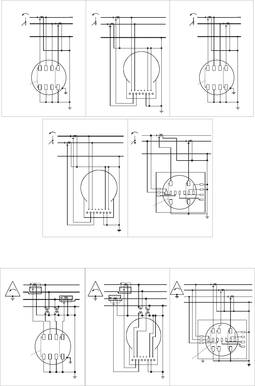
3 wire delta meters
3 wire wye meters
3
21
1
2
3
Form 45A
3 phase, 3 wire delta, 2 CTs, 0 or 2 PTs
23A06
Form 56S
3 phase, 3 wire delta, 2 CTs, 0 or 2 PTs
20E01
3
21
CIRCUIT
CLOSING
DEVICE
KZ
Y
1
2
3
1
2
N
N
2
1
Form 5A
2 phase, 3 wire wye, 2 CTs, no PTs
20E01
N
2
1
CIRCUIT
CLOSING
DEVICE
1
2
N
Form 5S
2 phase, 3 wire wye, 2 CTs, no PTs
20E01
L
O
A
D
2
N
1
1
2
N
N
2
1
Form 12S
2 phase, 3 wire wye, self-contained
20E01
1
2
N
L
O
A
D
1
2
N
N
2
1
Form 13A
2 phase, 3 wire wye, self–contained
20E01
1
2
N
L
O
A
D
2
N
1
N
2
1
Form 13S
2 phase, 3 wire wye, self-contained
20E01
Form 26S
2 phase, 3 wire wye, 2 CTs, 0 PTs
16C06
CIRCUIT
CLOSING
DEVICE
KZY
1
2
N
N
2
1
ALPHA meter
IL42-4001S
7
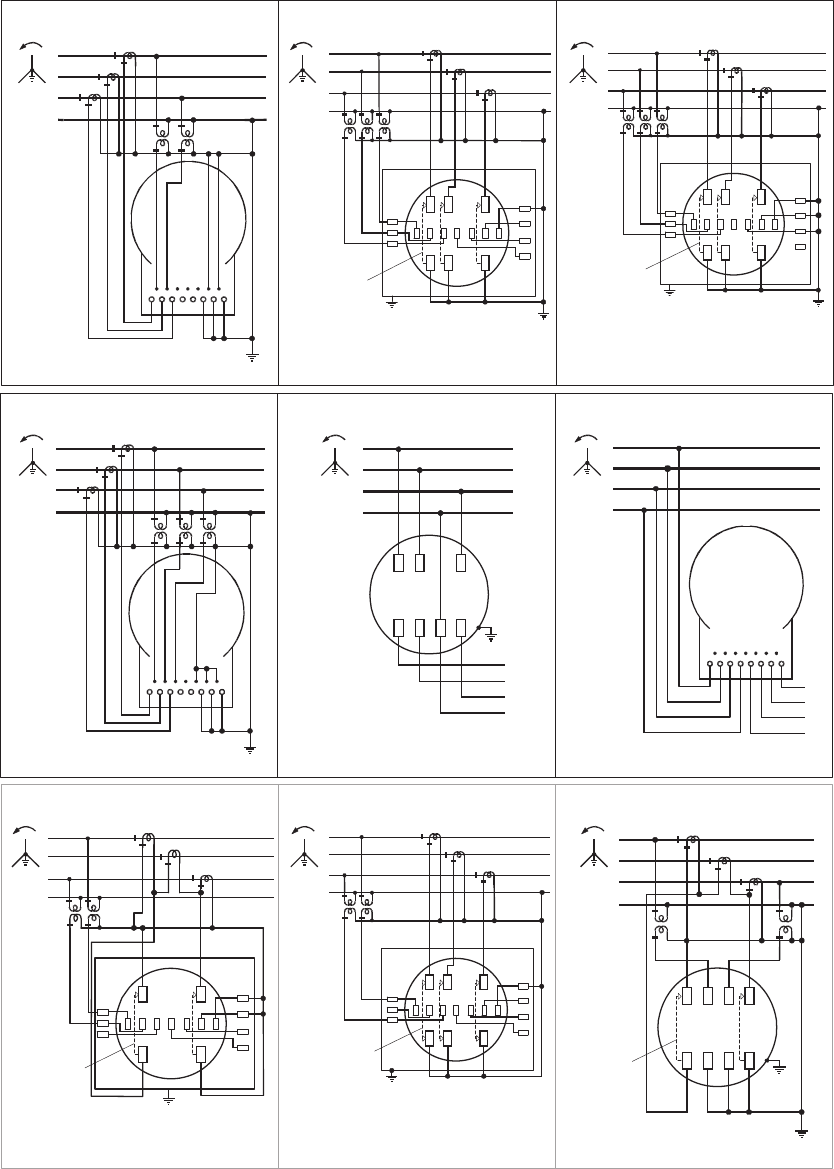
3 wire wye meters
4 wire delta meters
1
2
N
N
2
1
Form 35A
2 phase, 3 wire wye, 2 CTs, no PTs
20E01
20E01
Form 35S
2 phase, 3 wire wye, 2 CTs, no PTs
N
2
1
CIRCUIT
CLOSING
DEVICE
1
2
N
23A06
Form 45S
2 phase, 3 wire wye, 2 CTs, no PTs
N
2
1
CIRCUIT
CLOSING
DEVICE
1
2
N
1
2
N
N
2
1
Form 45A
2 phase, 3 wire wye, 2 CTs, no PTs
23A06
Form 56S
2 phase, 3 wire wye, 2 CTs, 0 PTs
16C06
CIRCUIT
CLOSING
DEVICE
KZY
1
2
N
N
2
1
Form 9S (Form 8S application)
3 phase, 4 wire delta, 3 CTs, no PTs
23E01
3
21
N
KZY
1
2
3
N
CIRCUIT
CLOSING
DEVICE
20E01
3
21
N
CIRCUIT
CLOSING
DEVICE
1
2
3
N
Form 5S
3 phase, 4 wire delta, 2 CTs, 2 PTs
Reduce CT ratio by ½
1
2
3
N
3
21
N
Form 5A
3 phase, 4 wire delta, 2 CTs, 2 PTs
20E01
Reduce CT ratio by ½
ALPHA meter
IL42-4001S
8
4 wire delta meters
CIRCUIT
CLOSING
DEVICE
1
2
3
N
3
21
N
Form 10S (Form 8S application)
3 phase, 4 wire delta, 3 CTs, no PTs
20E01
Wiring is different than a traditional
Form 8 meter
Form 10A (Form 8A application)
3 phase, 4 wire delta, 3 CTs, no PTs
23E01
1
2
3
N
3
21
N
Wiring is different than a traditional
Form 8 meter
1
2
3
L
O
A
D
1
N
3
N
2
3
21
N
Form 16S (Form 15S application)
3 phase, 4 wire delta, self-contained
20E01
1
2
3
N
L
O
A
D
1
2
3
N
3
21
N
Form 16A (Form 15A application)
3 phase, 4 wire delta, self-contained
20E01
Form 26S
3 phase, 4 wire delta, 2 CTs, no PTs
20C06
CIRCUIT
CLOSING
DEVICE
3
21
N
KZ
Y
1
2
3
N
Reduce CT ratio
by ½
CIRCUIT
CLOSING
DEVICE
3
21
N
KZ
Y
1
2
3
N
Form 26S
3 phase, 4 wire delta, 2 CTs, 2 PTs
29A02
Reduce CT ratio by ½
60 Hz only
ALPHA Plus with
autodetection enabled &
A3 ALPHA only
3
21
N
CIRCUIT
CLOSING
DEVICE
1
2
3
N
Form 35S
3 phase, 4 wire delta, 2 CTs, 2 PTs
Reduce CT ratio by ½
21C06
Form 35S
3 phase, 4 wire delta, 2 CTs, no PTs
3
21
N
CIRCUIT
CLOSING
DEVICE
1
2
3
N
Reduce CT ratio by ½
60 Hz only
ALPHA Plus with
autodetection
enabled &
A3 ALPHA only
16C06
1
2
3
N
3
21
N
Form 35A
3 phase, 4 wire delta, 2 CTs, 2 PTs
27A02
Reduce CT ratio by ½
ALPHA meter
IL42-4001S
9
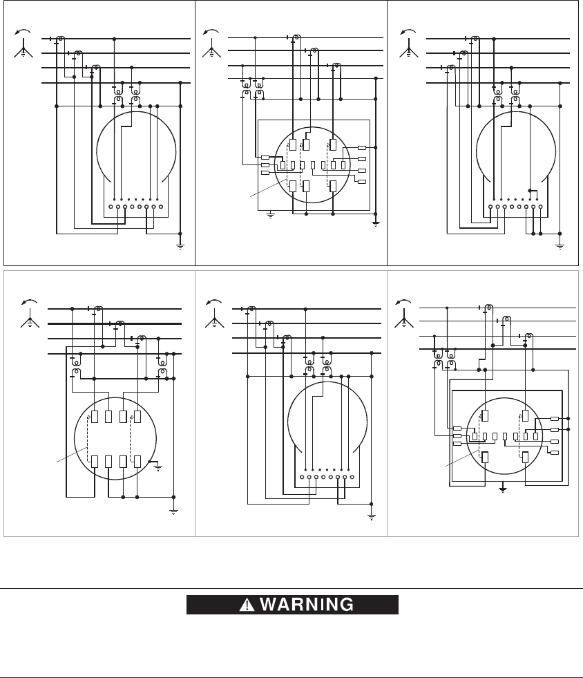
4 wire delta meters
4 wire wye meters
Form 45S
3 phase, 4 wire delta, 2 CTs, no PTs
3
21
N
CIRCUIT
CLOSING
DEVICE
1
2
3
N
Form 35A
3 phase, 4 wire delta, 2 CTs, no PTs
1
2
3
N
3
21
N
Form 45A
3 phase, 4 wire delta, 2 CTs, no PTs
1
2
3
N
3
21
N
Reduce CT ratio by ½ Reduce CT ratio by ½ Reduce CT ratio by ½
60 Hz only
ALPHA Plus
with
autodetection
enabled &
A3 ALPHA only
16C06
20C06
20C06
Form 56S
3 phase, 4 wire delta, 2 CTs, no PTs
CIRCUIT
CLOSING
DEVICE
3
21
N
KZ
Y
1
2
3
N
Reduce CT ratio by ½
16C06
N
2
13
CIRCUIT
CLOSING
DEVICE
1
2
3
N
Form 5S
3 phase, 4 wire wye, 3 CTs, 0 or 2 PTs
20E01
1
2
3
N
N
2
13
Form 5A
3 phase, 4 wire wye, 3 CTs, 0 or 2 PTs
20E01
N
2
13
CIRCUIT
CLOSING
DEVICE
KZY
1
2
3
N
Form 6S
3 phase, 4 wire wye, 3 CTs, 0 or 2 PTs
23E01
ALPHA meter
IL42-4001S
10
4 wire wye meters
1
2
3
N
N
2
13
Form 6A
3 phase, 4 wire wye, 3 CTs, 0 or 2 PTs
20E01
N
2
13
KZY
1
2
3
N
CIRCUIT
CLOSING
DEVICE
Form 9S
3 phase, 4 wire wye, 3 CTs, 0 or 3 PTs
23E01
N
2
13
1
2
3
N
CIRCUIT
CLOSING
DEVICE
23E01
Form 10S (Form 9S application)
3 phase, 4 wire wye, 3 CTs, 0 or 3 PTs
Does not strictly conform to the traditional Form 10S
wiring. It is intended for most 10S applications. One side
of each voltage section is wired common within the meter.
This wiring restricts the use of phase shifting trans-
formers to perform reactive measurement. If attempted,
equipment damage can occur.
1
2
3
N
N
2
13
Form 10A (Form 9A application)
3 phase, 4 wire wye, 3 CTs, 0 or 3 PTs
20E01
1
2
3
L
O
A
D
1
N
3
N
2
N
2
13
Form 16S (Form 14/16S application)
3 phase, 4 wire wye, self–contained
20E01
Form 16A (Form 14/16A application)
3 phase, 4 wire wye, self–contained
1
2
3
N
L
O
A
D
1
2
3
N
N
2
13
20E01
Form 26S
3 phase, 4 wire wye, 3 CTs, 0 or 2 PTs
N
2
13
CIRCUIT
CLOSING
DEVICE
KZY
1
2
3
N
20E01
Form 29S
3 phase, 4 wire wye, 3 CTs, 0 or 2 PTs
CIRCUIT
CLOSING
DEVICE
KZY
1
2
3
N
N
2
13
12B02
CIRCUIT
CLOSING
DEVICE
1
2
3
N
N
2
13
20E01
Form 35S
3 phase, 4 wire wye, 3 CTs, 0 or 2 PTs
ALPHA meter
IL42-4001S
11
4 wire wye meters
Do not disassemble the meter chassis or the electronic module from the meter chassis with power
present. Doing so could expose you to dangerous voltages, resulting in equipment damage, personal
injury, or death.
1
2
3
N
N
2
13
Form 35A
3 phase, 4 wire wye, 3 CTs, 0 or 2 PTs
20E01
CIRCUIT
CLOSING
DEVICE
KZY
1
2
3
N
N
2
13
Form 36S
3 phase, 4 wire wye, 3 CTs, 0 or 2 PTs
23E01
1
2
3
N
N
2
13
Form 36A
3 phase, 4 wire wye, 3 CTs, 0 or 2 PTs
20E01
Form 56S
3 phase, 4 wire wye, 3 CTs, 0 or 2 PTs
N
2
13
CIRCUIT
CLOSING
DEVICE
KZY
1
2
3
N
27A06
CIRCUIT
CLOSING
DEVICE
1
2
3
N
N
2
13
27A06
Form 45S
3 phase, 4 wire wye, 3 CTs, 0 or 2 PTs
1
2
3
N
N
2
13
Form 45A
3 phase, 4 wire wye, 3 CTs, 0 or 2 PTs
27A06

ALPHA meter
IL42-4001S
12
Battery installation and replacement
Time-of-use meters are typically shipped with the battery installed and connected. If the battery is
requested to be shipped disconnected, separately, or as a replacement, see the technical manual for
procedures for battery installation or replacement.
It is important that the battery not be connected unless the meter has been powered for at least 1
minute from the AC line within the last hour. It is important that the meter is not energized while the
battery is being installed or replaced (see the technical manual). After connecting the battery and re-
energizing the meter, the display should be checked to verify proper operation (that is, scrolling from
one display quantity to the next). Failure to follow the correct sequence for battery connection can
result in early battery discharge, the register being inoperative, or both.
Relay output color coding
Multiple relay output configurations are available with high voltage, solid state relays. The relay outputs
can be identified based on the number of output leads and their color coding. The following
configurations are available:
• 1 relay with 6 output leads (see Figure 1)
• 2 relays with 6 output leads (see Figure 1)
• 4 relays with 8 output leads (see Figure 2)
• 4 relays with 9 output leads (see Figure 3)
• 6 relays with 12 output leads (see Figure 4)
In all cases, the output leads exit the meter using approximately 24 inches of cable. Regardless of the
configuration present, the relays are assigned as follows:
• For ALPHA and ALPHA Plus meters:
- KYZ1 is dedicated to kWh delivered.
- KYZ2 is dedicated to kVAh delivered (for A1K or A1K+ meters) or kVARh delivered (for A1R or A1R+
meters)
- When present, KYZ3 is dedicated to kWh received.
- When present, KYZ4 is dedicated to kVAh received (for A1K or A1K+ meters) or kVARh received (for
A1R or A1R+ meters)
• For A3 ALPHA meters:
- All relays are fully programmable. Sources for the relays can be any basic metered quantity, EOI,
load control, PQM test failure, or relay-related alarm condition. See the A3 ALPHA Meter Technical
Manual (TM422190B or later) and the Metercat User Guide (TM42-2204B or later) for specific
information.
ALPHA meter
IL42-4001S
13
Figure 1. Color coding for 1 or 2 relays with 6 output leads
Figure 2. Color coding for 4 relays with 8 output leads
Figure 3. Color coding for 4 relays with 9 output leads
COMMON
NO
NC
Y1
Z1
Y2
Z2
K2
NC
NO
COMMON
Yellow
Black
Red
Wht/Blk
Blue
Orange
K1
RELAY A
RELAY B
ALPHA &
ALPHA Plus A3 ALPHA
Programmable
Programmable as
KYZ2, LC, or EOI
1 relay applications
use only Relay A
KYZ1
kWh delivered
Programmable
COMMON
NO Brown
Green
COMMON
NO
Red
Orange
NO
NC
Blue
Wht/Blk
NO
NC Yellow
Black
LC2
K
LC1
EOI
Z2
Y2
Z1
Y1
EOI
Load control
RELAY A
RELAY B
RELAY E
RELAY F
ALPHA &
ALPHA Plus A3 ALPHA
KYZ1
kWh delivered
Programmable as
KYZ2, LC, or EOI
Programmable
Programmable
Programmable
Programmable
COMMON
Y
Z
NC
NO
Yellow
Black
Red K
A3 ALPHA only
Programmable
RELAY A
COMMON
Y
Z
NC
NO
Wht/Blk
Blue
Red K
RELAY B
COMMON
Y
Z
NC
NO
Violet
White
Red K
RELAY C
COMMON
Y
Z
NC
NO
Gray
Wht/Brn
Red K
RELAY D
Programmable
Programmable
Programmable
ALPHA meter
IL42-4001S
14
Figure 4. Color coding for 6 relays with 12 output leads
COMMON Green
NO Brown
COMMON Red
NO Orange
NO Wht/Brn
NC Gray
NO White
NC Violet
NO Blue
NC Wht/Blk
NO Black
NC Yellow
LC1
LC2
RELAY A
RELAY B
RELAY C
RELAY D
RELAY E
RELAY F
ALPHA &
ALPHA Plus A3 ALPHA
Y1
Z1
Y2
Z2
Y3
Z3
Y4
Z4
EOI
K
KYZ1
kWh delivered
Programmable as
KYZ2, LC, or EOI
KYZ3
kWh received
KYZ4
kVARh/kVAh received
EOI
Load control
Programmable
Programmable
Programmable
Programmable
Programmable
Programmable
ALPHA meter
IL42-4001S
15
FCC compliance (Part 15.105)
Most meters are Class B devices. However, some meters in some applications, when equipped with
certain option boards, are certified as Class A devices. Additional FCC compliance information can be
found in the documentation shipped with each meter, option board, kit, or other meter component.
Class B devices
This equipment has been tested and found to comply with the limits for a Class B digital device,
pursuant to Part 15 of the FCC Rules. These limits are designed to provide reasonable protection
against harmful interference in a residential installation. This equipment generates, uses and can
radiate radio frequency energy and, if not installed and used in accordance with the instructions, may
cause harmful interference to radio communications. However, there is no guarantee that interference
will not occur in a particular installation. If this equipment does cause harmful interference to radio or
television reception, which can be determined by turning the equipment off and on, the user is
encouraged to try to correct the interference by one or more of the following measures:
• reorient or relocate the receiving antenna
• increase the separation between the equipment and the receiver
• connect the equipment into an outlet on a circuit different from that to which the receiver is connected
• consult the dealer or an experienced radio/TV technician for help
Class A devices
This equipment has been tested and found to comply with the limits for a Class A digital device,
pursuant to part 15 of the FCC Rules. These limits are designed to provide reasonable protection
against harmful interference when the equipment is operated in a commercial environment. This
equipment generates, uses, and can radiate radio frequency energy and, if not installed and used in
accordance with the instruction manual, may cause harmful interference to radio communications.
Operation of this equipment in a residential area is likely to cause harmful interference in which case
the user will be required to correct the interference at his own expense.
Compliance Statement (Part 15.19)
This device complies with Part 15 of the FCC Rules. Operation is subject to the following two conditions:
(1) This device may not cause harmful interference, and (2) this device must accept any interference
received, including interference that may cause undesired operation of the device.
Warning (Part 15.21)
Changes or modifications not expressly approved by Elster could void the user's authority to operate
the equipment.
Industry Canada compliance
This Class B digital apparatus complies with Canadian ICES-003. Cet appareil numérique de la classe
B est conforme à la norme NMB-003 du Canada.
ALPHA meter
IL42-4001S
16
DISCLAIMER OF WARRANTIES AND LIMITATIONS OF LIABILITY
There are no understandings, agreements, representations, or warranties either express or implied, including warranties of merchantability or fitness
for a particular purpose, other than those specifically set out by any existing contract between the parties. Any such contract states the entire
obligation of the seller. The contents of this document shall not become part of or modify any prior existing agreement, commitment, or relationship.
The information, recommendations, descriptions, and safety notices in this document are based on Elster Solutions, LLC experience and judgment
with respect to operation and maintenance of the described product. This information should not be considered as all-inclusive or covering all
contingencies. If further information is required, Elster Solutions, LLC should be consulted.
No warranties, either expressed or implied, including warranties of fitness for a particular purpose or merchantability, or warranties arising from the
course of dealing or usage of trade, are made regarding the information, recommendations, descriptions, warnings, and cautions contained herein.
In no event will Elster Solutions, LLC be responsible to the user in contract, in tort (including negligence), strict liability or otherwise for any special,
indirect, incidental, or consequential damage or loss whatsoever, including but not limited to: damage or loss of use of equipment, cost of capital,
loss of profits or revenues, or claims against the user by its customers resulting from the use of the information, recommendations, descriptions, and
safety notices contained herein.
© 2013 by Elster. All rights reserved. Produced in the United States.
Elster Solutions
Raleigh, North Carolina
Technical support: 800 338 5251
DISCLAIMER OF WARRANTIES REGARDING MODULE AND OPERATION
OF COMBINED MODULE/METER
This meter may include a third-party communication module (“Module”), installed at the customer's
request, that was NOT manufactured by Elster and is being installed AS IS. Therefore, without limiting
the generality of the foregoing disclaimer, ELSTER DISCLAIMS ANY AND ALL WARRANTIES, EXPRESS OR
IMPLIED, REGARDING THE MODULE AND OPERATION OF THE COMBINED MODULE/METER WITH THE
ANSI OR FCC REQUIREMENTS. While Elster may act as a broker for the Module manufacturer’s
warranties, any express or implied warranty regarding the Module or operation of the combined
Module/meter, to the extent that such warranty may exist, is provided SOLELY BY THE MODULE’S
MANUFACTURER.