Elster Solutions ZGB1 2.4 GHz Communications Option Board User Manual G8J ZGB1 Installation Guide
Elster Solutions, LLC 2.4 GHz Communications Option Board G8J ZGB1 Installation Guide
users manual

2.4 GHz Communications Option Board
Installation Guide
Elster Integrated Solutions, LLC 12/3/2008
208 South Rogers Lane
Raleigh, NC 27610
(919) 250-5700
Fax (919) 250-5439 1 of 8
2.4 GHz Communications Option Board
Installation Guide

2.4 GHz Communications Option Board
Installation Guide
Elster Integrated Solutions, LLC 12/3/2008
208 South Rogers Lane
Raleigh, NC 27610
(919) 250-5700
Fax (919) 250-5439 2 of 8
TABLE OF CONTENTS
1. OVERVIEW.............................................................................................................. 3
1.1. Document Purpose ........................................................................................................................................3
1.2. FCC Information to the User .......................................................................................................................3
1.2.1. Product Information................................................................................................ 3
1.2.2. General Information................................................................................................ 3
1.2.3. Labeling .................................................................................................................. 4
1.2.4. RF Exposure............................................................................................................ 4
1.2.5. Co-Located Transmitters ........................................................................................ 4
1.2.6. Additional Testing .................................................................................................. 4
2. INSTALLATION....................................................................................................... 5
2.1. Internal Use....................................................................................................................................................5
2.2. External use ...................................................................................................................................................5
2.3. Clearance .......................................................................................................................................................5
3. 2.4 GHZ COMMUNICATIONS OPTION BOARD DESCRIPTION........................... 6
4. ELECTRONIC ASSEMBLY DESCRIPTION ........................................................... 6
4.1. Specifications .................................................................................................................................................6
4.2. Host Connector..............................................................................................................................................7
5. REVISION HISTORY ............................................................................................... 8

2.4 GHz Communications Option Board
Installation Guide
Elster Integrated Solutions, LLC 12/3/2008
208 South Rogers Lane
Raleigh, NC 27610
(919) 250-5700
Fax (919) 250-5439 3 of 8
1. OVERVIEW
1.1. DOCUMENT PURPOSE
This document describes the requirements for installation and use of the 2.4 GHz
Communications Option Board functions as required for FCC Certification.
1.2. FCC INFORMATION TO THE USER
1.2.1. Product Information
Model ZOB FCC ID G8J ZGB1 IC: 4557C ZGB1
This device complies with Part 15 of the FCC rules and with
Industry Canada RSS-GEN. Operation of this device is subject
to the following 2 conditions: (1) This device may not cause harmful
interference, and (2) this device must accept any interference
received including any interference that may cause undesired operation.
1.2.2. General Information
Changes or modifications to the equipment not expressly approved by Elster could void the
user's authority to operate this equipment.
NOTE: This equipment has been tested and found to comply with the limits for a Class B
digital device, pursuant to part 15 of the FCC Rules. These limits are designed to provide
reasonable protection against harmful interference in a residential installation. This
equipment generates, uses and can radiate radio frequency energy and, if not installed and
used in accordance with the instructions, may cause harmful interference to radio
communications. However, there is no guarantee that interference will not occur in a
particular installation. If this equipment does cause harmful interference to radio or television
reception, which can be determined by turning the equipment off and on, the user is
encouraged to try to correct the interference by one or more of the following measures:
—Reorient or relocate the receiving antenna.
—Increase the separation between the equipment and receiver.
—Connect the equipment into an outlet on a circuit different from that to which the receiver is
connected.
—Consult the dealer or an experienced radio/ TV technician for help.
A separation distance of at least 8 inches (20 cm) is to be maintained between the antenna
and the human body and must not be co-located or operated in conjunction with any other
transmitter or antenna.
The Term “IC” before the certification/registration number only signifies that the Industry
Canada technical specifications were met.
2.4 GHz Communications Option Board
Installation Guide
Elster Integrated Solutions, LLC 12/3/2008
208 South Rogers Lane
Raleigh, NC 27610
(919) 250-5700
Fax (919) 250-5439 4 of 8
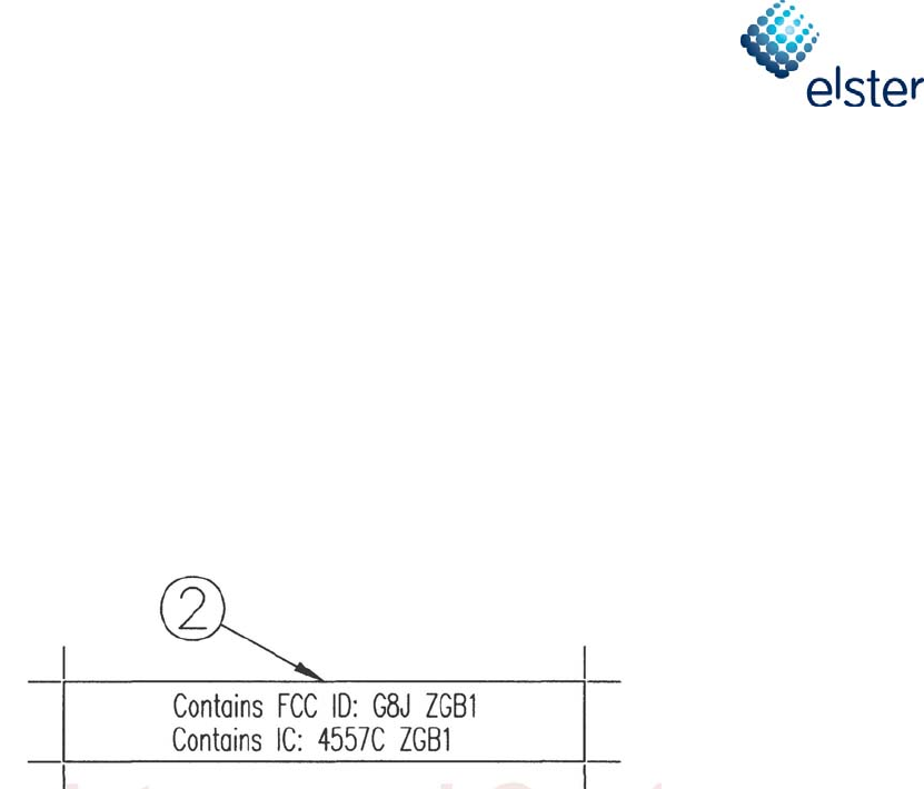
1.2.3. Labeling
If the FCC ID is not visible when the module is installed inside another device, then the
outside of the device into which the module is installed must also display a label referring to
the enclosed module. This exterior label can use wording such as the following: “Contains
Transmitter Module FCC ID: G8J ZGB1” or “Contains FCC ID: G8J ZGB1.” Any similar
wording that expresses the same meaning may be used. The Grantee may either provide
such a label, an example of which must be included in the application for equipment
authorization, or, must provide adequate instructions along with the module which explain this
requirement. In the latter case, a copy of these instructions must be included in the
application for equipment authorization.
1.2.4. RF Exposure
A separation distance of at least 20cm from the end user is required.
1.2.5. Co-Located Transmitters
Provisions have been provided on the Interface Connector such that this device will be
disabled if another co-located transmitter is required to transmit.
This device “may not” be operated as a co-located transmitter with other transmitting devices
unless certification is obtained as a new end product.
1.2.6. Additional Testing
Users incorporating this device into their product must test the complete system, with radio
module installed, against the appropriate standard for the host device.
While the applicant for a device into which an authorized module is installed is not required to
obtain a new authorization for the module, this does not preclude the possibility that some
other form of authorization or testing may be required for the device.

2.4 GHz Communications Option Board
Installation Guide
Elster Integrated Solutions, LLC 12/3/2008
208 South Rogers Lane
Raleigh, NC 27610
(919) 250-5700
Fax (919) 250-5439 5 of 8
2. INSTALLATION
This device is intended to be used as part of an automated utilities meter reading network
and uses proprietary communications and data to communicate with another host device.
2.1. INTERNAL USE
This device was designed to fit into The Elster Electricity LLC REX2 series of utilities electric
meters. Provisions in the case mechanics have been provided to accept the device as an
insert-able option card. The interface connector is designed to mate directly with the main
board in the electric meter. This device is installed when the electric meter is manufactured at
the factory.
All additional required FCC testing and control for proper operation to meet FCC
requirements as a final product have been met.
2.2. EXTERNAL USE
This device is not for sale to the general public.
Sale of this device outside of the company will be strictly controlled to ensure its compliance.
2.3. CLEARANCE
The device should be installed in a manner such that a clearance distance of 8mm will be
maintained from the front and back of the device to prevent adversely affecting the antenna
incorporated onto the Circuit Board.
Antenna testing in the intended host device did not show any significant deterioration in
performance caused by close proximity of wiring or case mechanics. Good engineering
practice dictates that the antenna be kept clear of obstacles to ensure maximum
performance.
2.4 GHz Communications Option Board
Installation Guide
Elster Integrated Solutions, LLC 12/3/2008
208 South Rogers Lane
Raleigh, NC 27610
(919) 250-5700
Fax (919) 250-5439 6 of 8
3. 2.4 GHZ COMMUNICATIONS OPTION BOARD DESCRIPTION
The 2.4 GHz Communications Option Board is part of a demand response system that
communicates with home thermostats and other devices that are part of the utilities industry.
When installed into an electric utilities meter, the 2.4 GHz Communications Option Board is
capable of communicating in an automated meter reading (AMR) system via the interface
connector.
4. ELECTRONIC ASSEMBLY DESCRIPTION
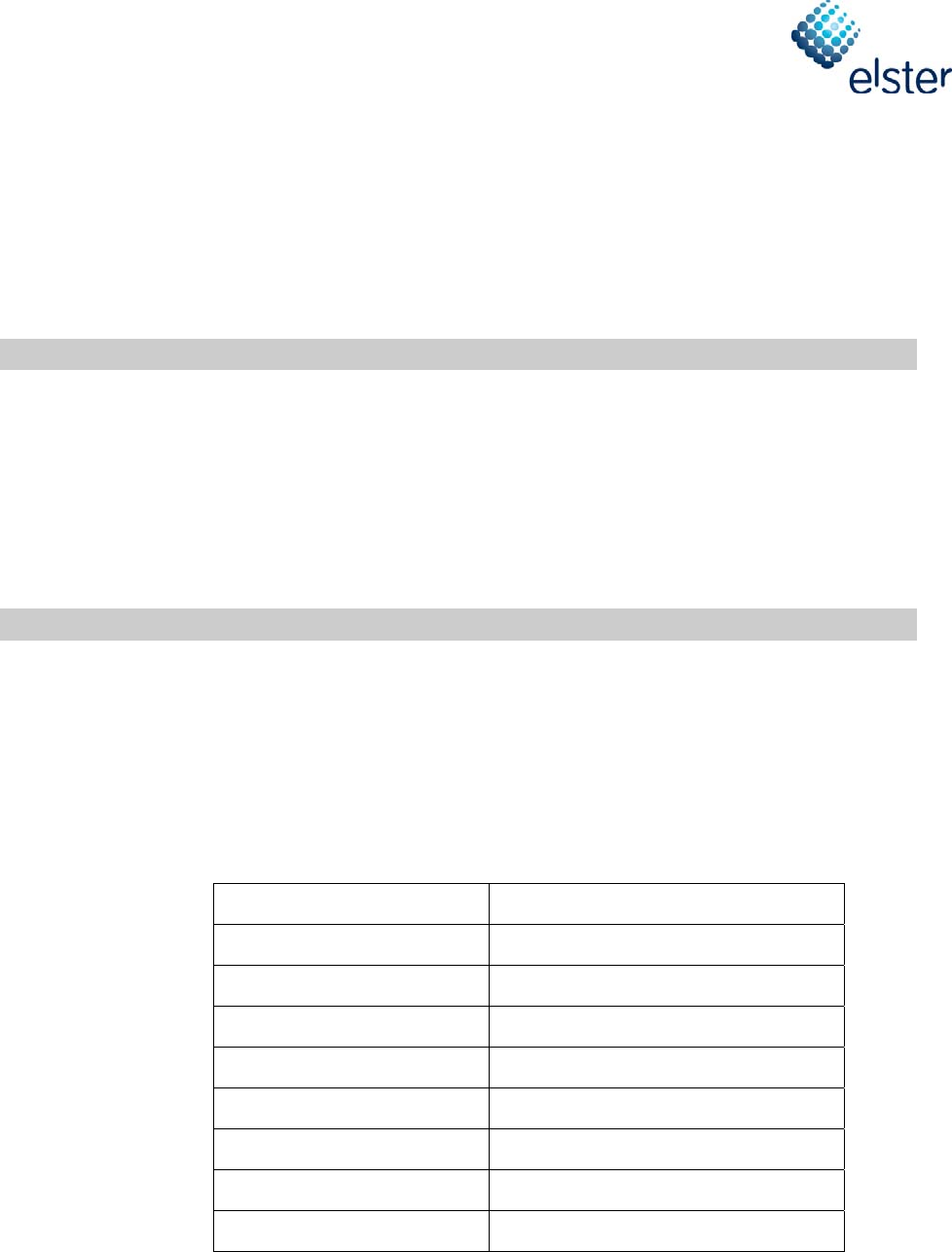
4.1. SPECIFICATIONS
The 2.4 GHz Communications Option Board is an intentional radiator and is classified as a
Part 15.247 device. The critical specifications of the 2.4 GHz Communications Option Board
are listed in the following table:
Frequency Band 2405 – 2465 MHz
Classification DSS
Maximum Output Power 0.080W (+19 dBm)
Channel Spacing 5 MHz
Channel 6 dB Bandwidth 1.5 MHz
Number of Channels 13
Modulation O-QPSK
Power Supply 18VDC Nom.
Current Draw 40mA@18V

2.4 GHz Communications Option Board
Installation Guide
Elster Integrated Solutions, LLC 12/3/2008
208 South Rogers Lane
Raleigh, NC 27610
(919) 250-5700
Fax (919) 250-5439 7 of 8
4.2. HOST CONNECTOR
Host Connector pins
1,2 Unregulated 18VDC Power Source.
4 Enables the 3.3V regulator. Will power down Board fully.
5 Control to indicate that another device wishes to transmit.
Will cause the device to immediately cease all transmission.
Used for co-located transmitter applications.
6 Host can signal an upcoming loss of power to provide time for
storage of critical data.
7 Places the board into a low power mode, so the host can have
access to full power from its power supply.
9 Processor digital data communications.(TX)
9 Processor digital data communications.( TBL Write)
10 Processor digital data communications.(RX)
3,11,12,13,14 NC
15,16 GND
2.4 GHz Communications Option Board
Installation Guide
Elster Integrated Solutions, LLC 12/3/2008
208 South Rogers Lane
Raleigh, NC 27610
(919) 250-5700
Fax (919) 250-5439 8 of 8
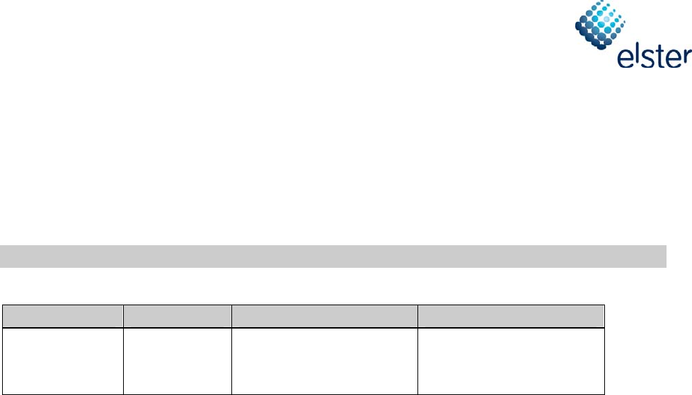
5. REVISION HISTORY
Author Date Modification Telephone Number
John Casaer Nov. 25, 2008 Initial Draft 919-250-5440
COPYRIGHT NOTICE
Copyright © 2003 by Elster Integrated Solutions, LLC. All rights are reserved.
No part of this document may be reproduced, transmitted, processed or recorded by any means or form, electronic, mechanical,
photographic or otherwise, translated to another language, or be released to any third party without the express written consent of
Elster Integrated Solutions, LLC
Printed in the United States of America