Elta Systems 2107 Radar (human detection system) User Manual
Elta Systems Ltd. Radar (human detection system)
manual

Unclassified
HUMAN DETECTION SYSTEM
EL/M - 2107
(HDS)
USER MANUAL

- 2 -
This document contains proprietary information of ELTA Systems Ltd.
TABLE OF CONTENTS
1. SCOPE....................................................................................................................4
1.1.
System Goal.........................................................................................................................5
1.2.
Applicable Documents ........................................................................................................5
2. SYSTEM OVERVIEW.........................................................................................6
3. HDS - DESCRIPTION AND TECHNICAL
SPECIFICATIONS ...............................................................................................7
3.1.
Radar Overview...................................................................................................................7
3.2.
HDS Specifications..............................................................................................................9
3.3.
Probability of Detection.......................................................................................................9
3.4.
Human Detection System - HDS.......................................................................................10
Transceiver 11
3.4.1.
Antenna Array ...................................................................................................................12
3.4.2.
Connecting Cables.............................................................................................................13
3.4.3.
Electro Optical Tracking (optional)...................................................................................16
3.5.
System Operation ..............................................................................................................17
3.5.1.
Control Buttons .................................................................................................................18
3.5.1. 19
3.6.
Environmental Conditions.................................................................................................19
3.7.
EL/M-2107 Operation Procedure ......................................................................................20
3.7.1.
At start up standby command will send to the Radar ........................................................20
3.7.2.
Waiting for legal Ack from the radar, If there isn't Ack or the Ack was
illegal then send again the command until three times, if the command
was fail then going to recovery procedure.........................................................................20
3.7.3.
Waiting for Radar Wakeup command...............................................................................20
3.7.4.
After gets wakeup command, send Operate command, operate
command is dividing to three commands:.........................................................................20
3.7.5.
In search state if there isn’t plots from the radar, then go to recovery
state,...................................................................................................................................20
3.7.6.
Every communication fail or radar fail will be written to LOG file with
the fail Time.......................................................................................................................20

- 3 -
This document contains proprietary information of ELTA Systems Ltd.
4. Installation Instructions for ELM – 2107 system............................................. 22
4.1.
Software installation..........................................................................................................22
4.2.
Hardware installation.........................................................................................................22
5. Notes and warning...............................................................................................24
- 4 -
This document contains proprietary information of ELTA Systems Ltd.
1. SCOPE
This document presents the Human Detection System (HDS)
developed and manufactured by ELTA, a subsidiary of Israel
Aircraft Industry Ltd. Given are a general radar overview,
technical specification and matters related to supply support
provisions and quality assurance.
The purpose of this document is to assist a potential user in the
assessments of the radar proposed, operational constrains,
human and technical resources at his disposal etc. Also, it is in
both; Manufacturer and potential user best interest, that the latter
establish an approach based on the information enclosed and his
requirements as regards the prospect of operating the HDS.

- 5 -
This document contains proprietary information of ELTA Systems Ltd.
HDS and IBM PC compatible
1.1. System Goal
The HDS goal is to detect and automatically alert entering and
outgoing moving persons and vehicles within defined preset
boundaries. As it is a very complicated process, customer should
have an operational watch-keeping concept, in which the HDS
will be one element in the integrated Sensors, Monitors,
Command Communication and Control system.
1.2. Applicable Documents
The following documents of the issue in effect 1999 form a part
of this specification to the extent specified herein. In the event
of conflict between the documents referenced herein and the
contents of this specification or the detailed design which is an
Intellectual Proprietary (IP) of ELTA, the contents of this
specification and IP design shall be considered a superseding
requirement.
a. ISO-9001
b. MIL-HDBK 217F
c. MIL-STD-810C
d. MIL-STD-1472D
e. RS-232
f. RS-422

- 6 -
This document contains proprietary information of ELTA Systems Ltd.
2. SYSTEM OVERVIEW
The system is based on ELTA’s vast experience in
high-resolution technology and innovative radars.
The system automatically detects moving objects and
persons within the covered area.
It allows segregation of persons maneuvering in
permitted zones and those who try to intrude
unauthorized areas.
The system allows continuous monitoring and
detection in all weather conditions.
Programmable automatic alerts according the areas
status. (Restricted zones according to time
frames,
buffer zones, etc’)
Applications
• Installations’ Security
Securing the inside and the outside boundaries such as:
power plants, factories, army bases, air and sea- ports,
jails, embassies and other governmental facilities etc’
• Traffic Control
Tracks authorized and non permitted personnel and
vehicles within selected areas
• Border protecting
Enhancing the border guard capability by monitoring
and detecting maneuvers away from the border
line/fence, thus helping to prevent any intrusion even
before the arrival of the potential trespasser to the border
line/fence.
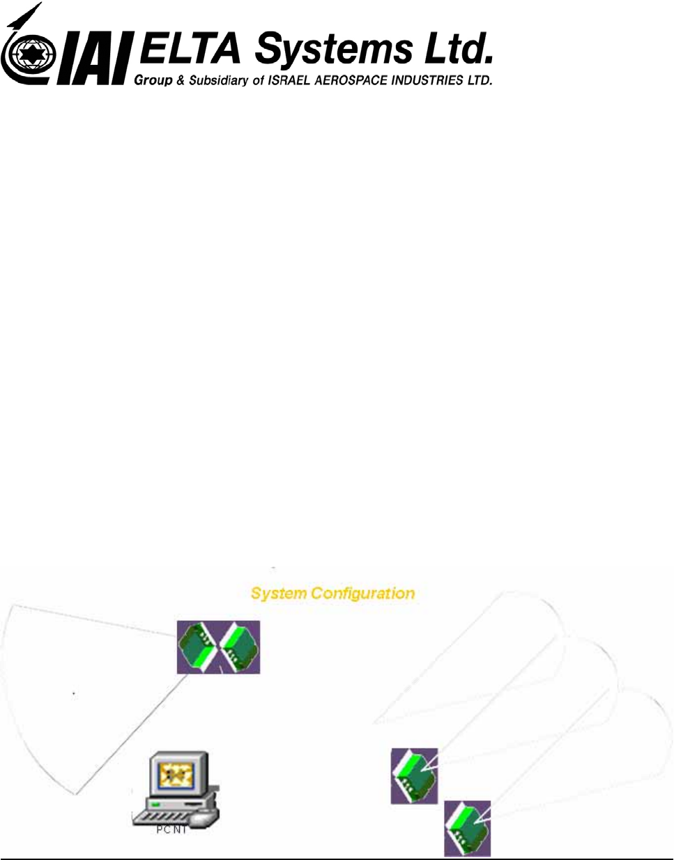
Singular and Neted Configurations
The system provides a very accurate and reliable tactical
situation of selected areas together with exceptionally
low fault alarms rate and a very low operator's workload
all year long in all weather condition.
HDS can be built up gradually by simply adding unites to
the network of the system.

- 7 -
This document contains proprietary information of ELTA Systems Ltd.
Features
• Automatic detection of moving targets
• High range accuracy and resolution.
• Visual and audio alarms for each
detection or when objects are detected
in restricted zone.
• PC NT based control unit with friendly
HMI.
• Simple and easy to operate, very low
workload on operator.
• Display background area on actual
digital map/picture.
• Lightweight and low power
consumption.
• Simple networking of several main units
to one PC.
• Capability to operate via remote control
from a distant command post.
• Interoperability with additional sensors
and security systems.
• Easy installation and concealment and
Modular assembly
• High reliability, low maintenance, no
calibration needed.
• Growth potential
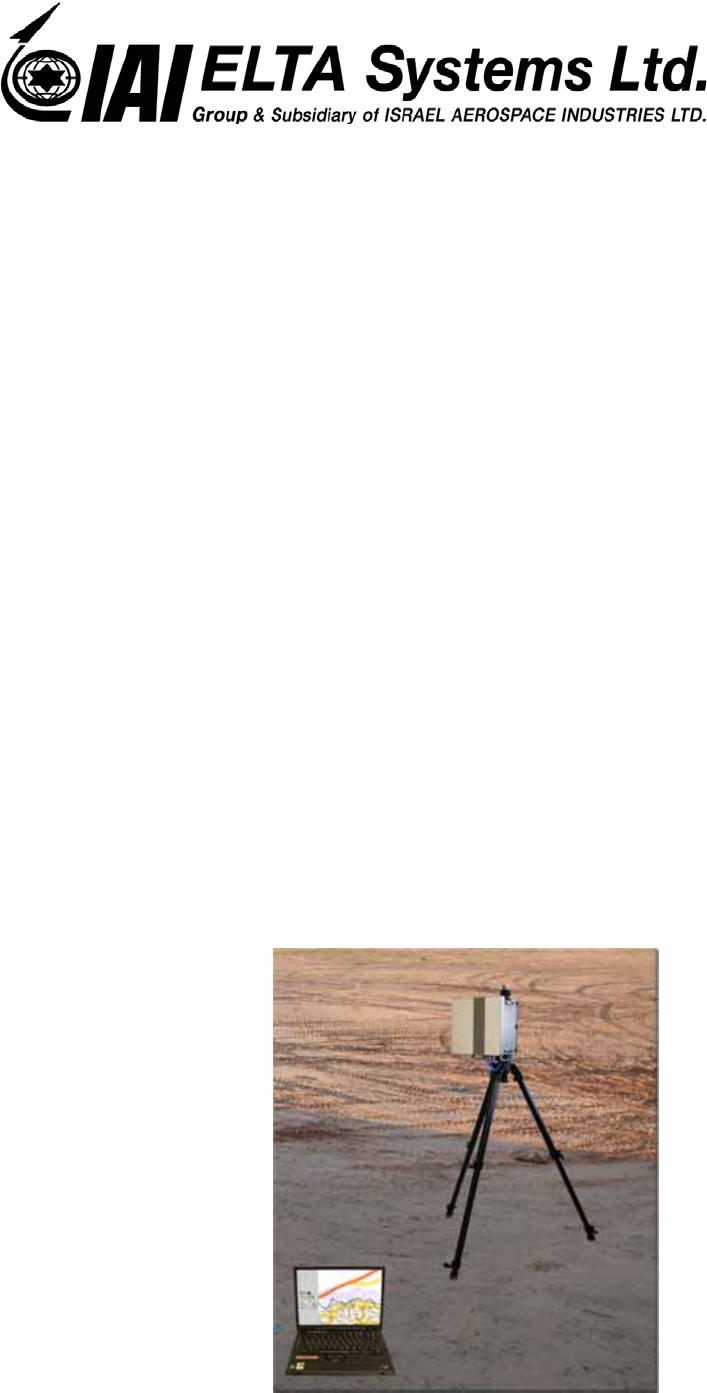
HDS - DESCRIPTION AND TECHNICAL SPECIFICATIONS
3.1. Radar Overview
The HDS is a sensor that detects moving human being, vehicles
and other objects that might move in the physical and electronic
boundaries as defined in this specification. The radar is
comprised of a transceiver LRU connected to an antennae array
module that were design to be mounted on top of a mast,
buildings or any other static component of infrastructure
providing undisturbed line of sight in the sector of interest. The
installation asset, which is an external item, may be chosen by

- 8 -
This document contains proprietary information of ELTA Systems Ltd.
the users to conform to their needs. The HDS detects and
classifies moving objects in real time within a defined false
alarm rate (Detection and false alarm rate are shown in
paragraph 2.3). The location and track of these targets may be
then automatically processed, monitored and displayed as an
alert in real time to attract the operators’ attention to a
immediate and real hazard. The radar has a modular hardware
and software structure and is noted by its high reliability and
fully digital solid-state design.
An IBM PC compatible with a color display, enabling the
automatic detection operation, may perform the control and
display functions of the HDS.
As an option, the radar can send the detection to a central
computer via RS-422 or RS-232.
A Low Light TV camera or other visual sensors may be
controlled for automatic locking and tracking upon alert of
detection. The slaving of the visual sensor is done via the IBM
PC compatible and RS-422 line.

- 9 -
This document contains proprietary information of ELTA Systems Ltd.
3.2. HDS Specifications
Following are the HDS specifications:
a. Working method: high resolution Doppler radar
b. Frequency: C band
c. Max range Detection: 300m for persons
d. Min range Detection: 15m
e. Detection Speed >= 0.1 m/sec
f. Target separation: Azimuth 10º
Range > 7m
g. Range accuracy: ±1m
h. Azimuth accuracy: ±3º
i. Beam with: Horizontal 80º
Vertical 15º
j. Power: 24v
k. Power consumption: 20w
l. Communication: via RS- 422
m. MEU weight: 3.5kg
3.3. Probability of Detection
The HDS was tested in various terrain, roads and vegetation environment as:
gravel, sand, asphalt, agriculture terrain and natural vegetation. The results,
based on statistical basis are 90% detection rate for regular moving targets
(0.5m²).
- 10 -
This document contains proprietary information of ELTA Systems Ltd.
3.4. Human Detection System - HDS
The HDS is based on an Ultra Wide Bandwidth (UWB) waveform and
processing logic, enabling high resolution imaging of moving objects, in the
area of interest. Advanced state-of-the-art digital processing and software
algorithms are used to perform real time detection of moving objects,
measurements, analysis and recognition at a low false alarm level - thus
enabling reliable, automatically alerted, real time watch keeping operation.
The HDS consists of an Antenna array, a Transceiver and connecting cables.
It also may include in an integrated configuration a visualization system to
support identification and recognition.
- 11 -
This document contains proprietary information of ELTA Systems Ltd.
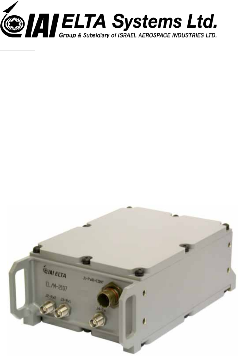
Transceiver
The transceiver is a self-contained unit incorporating a number of
components in a ruggedized case 15x23x9 cm in size and 2 Kg weight. The
transceiver is full solid state and digital, it includes smart waveform
generator, for the HDS transmitter and receiver, signal and data
processing/control and the power supply.
c. Transceiver
- 12 -
This document contains proprietary information of ELTA Systems Ltd.
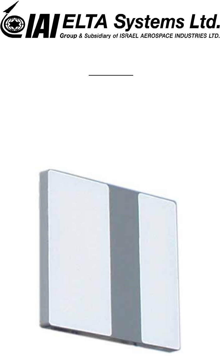
3.4.1. Antenna Array
The Antenna array is comprised of up to two (2) antenna array modules. The
system works with a single transceiver one transmitting antenna module and
two receiving antennas module. The antenna modules are separated, covered
by radome.
Antenna Array (Application demonstrated for example only)

- 13 -
This document contains proprietary information of ELTA Systems Ltd.
3.4.2. Connecting Cables
The HDS also includes all the (HDS internal) connecting cables between the
HDS components: - between the Antenna Array, the Transceiver module
and the External customer’s PC display station (cables will be applied in
accordance with customers’ requirements).

- 14 -
This document contains proprietary information of ELTA Systems Ltd.
3.4.2.1.
ELM-2107 Power and communication Connector for version
1021E500-001
This connector is numbered J1 Type: D38999/26WB35SN
PIN No' FUNCTION
1 24VRTN
2 (spare)
3 (spare)
4 (spare)
5 (spare)
6 +24VDC
7 (spare)
8 Tx+
9 Rx+
10 (spare)
11 GND
12 Tx-
13 Rx-
- 15 -
This document contains proprietary information of ELTA Systems Ltd.
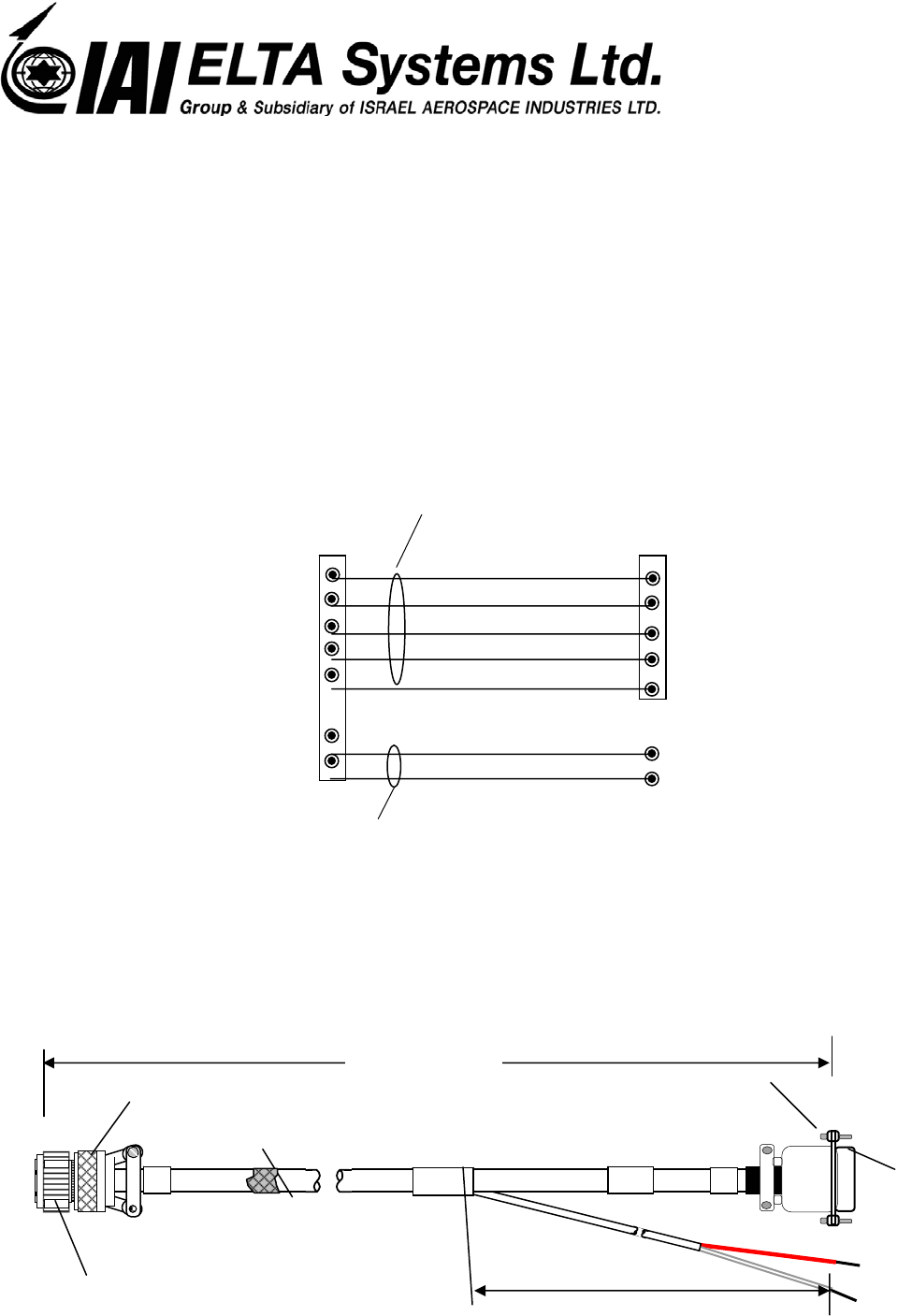
3.4.2.2. Connection and Power Cable W12 1013D712-001
5 mete
r
10 meter
P
WP
1.
RILSAN
GND
D38999/26WB35SN
+
Power Su
pp
l
y
M85049/38-11W M85049/48-1-1F
M
1
9
8
1
1
1
6
8
3
7
2
4
P
P
CONN
D-TYPE-9 PIN
CONN
D38999/26WB35SN
VCC
GND
GND
Tx-
Tx+
Rx+
Rx-
RS422/RS232 Adapter
Twisted per 22 #
2x2x62095 -Comm Cable

- 16 -
This document contains proprietary information of ELTA Systems Ltd.
3.4.3. Electro Optical Tracking (optional)
The detected Targets will be automatically displayed, an audio
alert will be activated and the camera will lock and track the
detected object. The HDS provides for a command from the
HDS through an RS-422 communication link to a controller that
will operate the Electro Optical camera and tracker.

- 17 -
This document contains proprietary information of ELTA Systems Ltd.
3.5. System Operation
The HDS operating control consol is based on an IBM PC (or compatible) with a
color display, which controls all the HDS functions. The Operating Control
Software is written under Window NT in C++. The PC controls the HDS via RS-
232 or RS-422. The control is done throughout windows on the screen, using a
mouse that features the following buttons and displays:
a. Standby-initiates communication between HDS components and the PC and go to
CW mode and processing the signals,.
b. Search Mode- initiates the command for scanning, detecting and data processing.
- 18 -
This document contains proprietary information of ELTA Systems Ltd.
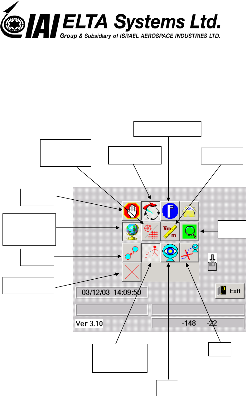
3.5.1. Control Buttons
Enable/Disable
Map
Stand By
Search Mode
Technicians Button
Vector
Cancel Sound
Enable/Disable
Track history
NA
NA
Zoom
Units
Enable/Disable
Grid

- 19 -
This document contains proprietary information of ELTA Systems Ltd.
3.6. Environmental Conditions
The HDS maintains its specified performance when exposed to
the environmental conditions as detailed herein:
a. Operating temperature- -15°C to +55°C
b. Storage- -40°C to +85°C
c. Humidity- Up to 95% relative humidity
d. Salt atmosphere- Exposure to salt sea atmosphere (48 hours,5%
NaCL)
e. Wind- During operation - 50 Knots
f. Sand and dust- Expositor to sand and dust particles as encountered in
operational areas (11grams/M3, wind 50 knots)
g. Solar radiation- Exposure to solar radiation(105 W/ft2)
h. Vibration- Sinusoidal vibration in accordance with MIL-STD-
810C, method 514.2, proc.VIII.
i. Mechanical shock-Shock characteristics: half Sine wave 30 G, 11 msec.

- 20 -
This document contains proprietary information of ELTA Systems Ltd.
3.7. EL/M-2107 Operation Procedure
3.7.1. At start up standby command will send to the Radar
3.7.2. Waiting for legal Ack from the radar, If there isn't Ack or the Ack was
illegal then send again the command until three times, if the command was fail
then going to recovery procedure.
3.7.3. Waiting for Radar Wakeup command
3.7.4. After gets wakeup command, send Operate command,
operate command is dividing to three commands:
3.7.4.1.Send params command
3.7.4.2.Status command
3.7.4.3.Search command
After each send command the control unit should wait for Ack
from the radar and behave like paragraph 3.7.2
3.7.5. In search state if there isn’t plots from the radar, then go to
recovery state,
3.7.6. Every communication fail or radar fail will be written to

- 21 -
This document contains proprietary information of ELTA Systems Ltd.
LOG file with the fail Time.

- 22 -
This document contains proprietary information of ELTA Systems Ltd.
4. INSTALLATION INSTRUCTIONS FOR ELM – 2107
SYSTEM
4.1. Software installation
1. Insert the installation CD.
2. Select the RUN option from the START menu.
3. Click on Browse..
4. Select file: install.bat
5. Click on Open.
6. The install file will create a directory named HDS and copy some files to
it.
7.
Create new shortcut named HDS from c:\hds\Programs\HDS.exe
4.2. Hardware installation
General: The ELM 2107 is fixes device and placed on the roof
or a pole
1. Connect the radar to the holder (see attached pictures); use 4 NF… screws (provided
with the radar).
Make sure that the connectors are facing down and the elevation slot on the holder is
facing up.
2. Install the holder with the radar on a pole (2.5 – 3.5m above ground level), the
elevation should be 0 to –3 deg relative to the ground, make sure that there are no
blocking objects in front of the radar (like: fences, poles, walls, trees…)
3. Connect P1 connector to J1 on the radar panel.
4. Connect the other side of the cable to COM1 of the PC (RS232 9pin Dtype connector
of the RS422/RS232 converter).
5. Connect the white wire (+24volts) to the positive output of the power supply, the
black wire to the negative output of the P.S.
6. The recommended power supply is 24 VDC / 1AMP min. (the min. voltage is
20VDC and the max. voltage is 30VDC). converter Always Make sure that the 232 To avoid damage to the RS!!WARNING
RS232 converter is connected to the PC and the PC is turned on, before turning on
the power supply.
7. Turn on the PC, make sure that the HDS icon is on screen.

- 23 -
This document contains proprietary information of ELTA Systems Ltd.
8. Turn on the power supply.
9. Activate the HDS program, make sure that there is a green light on upper left of the
screen. (Red light indicates no communication) .
10. The Radar is now ready for detection.
11. Detections will be marked in red dots, the blue dots are under the program
threshold.

- 24 -
This document contains proprietary information of ELTA Systems Ltd.
5. NOTES AND WARNING
NOTE: This equipment has been tested and found to comply with the limits for
a Class A digital device, pursuant to part 15 of the FCC Rules. These
limits are designed to provide reasonable protection against harmful
interference when the equipment is operated in a commercial
environment. This equipment generates, uses, and can radiate radio
frequency energy and, if not installed and used in accordance with the
instruction manual, may cause harmful interference to radio
communications. Operation of this equipment in a residential area is
likely to cause harmful interference in which case the user will be
required to correct the interference at his own expense.
WARNING:
Changes or modifications to this equipment not expressly approved by
the party responsible for compliance (ELTA Ltd.) could void the user’s
authority to operate the equipment
.
WARNING:
"To comply with FCC RF exposure requirements, the antenna used for
this transmitter must be installed to provide a separation distance of at
least 2 meters from all persons."