Eltek Technologies A7200 ADSL WIFI Router User Manual
Eltek Technologies Ltd ADSL WIFI Router
UserManual.wiki
>
Eltek Technologies
>
A7200 User Manual
User manual
Navigation menu
Upload a User Manual
Namespaces
Wiki Guide
HTML
PDF
Info
Views
User Manual
Discussion / Help
Navigation
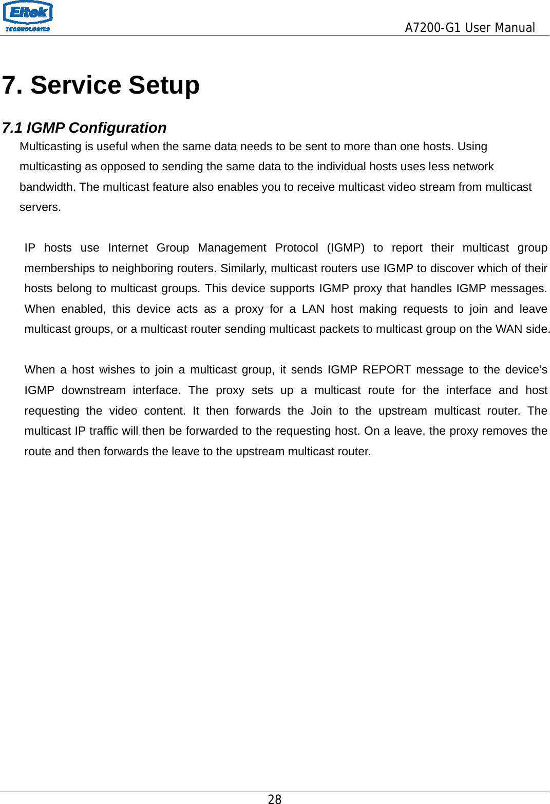
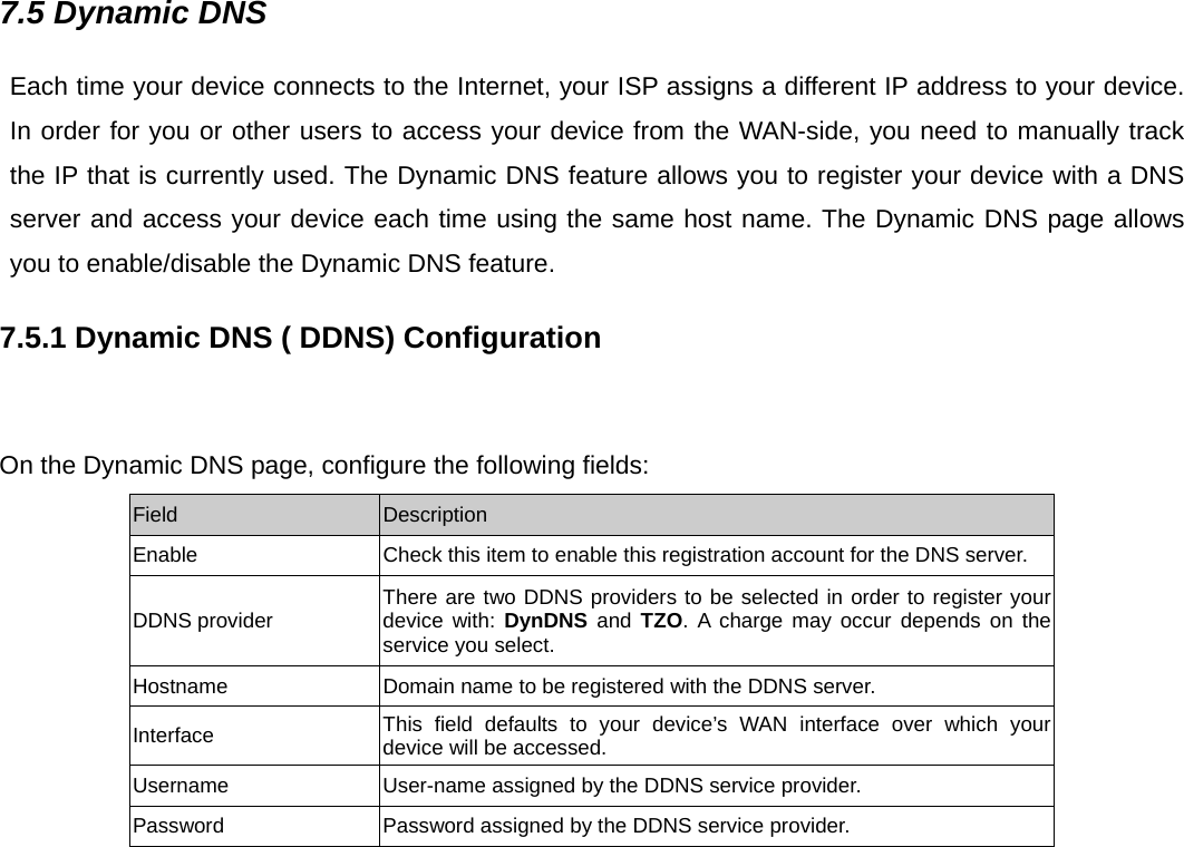
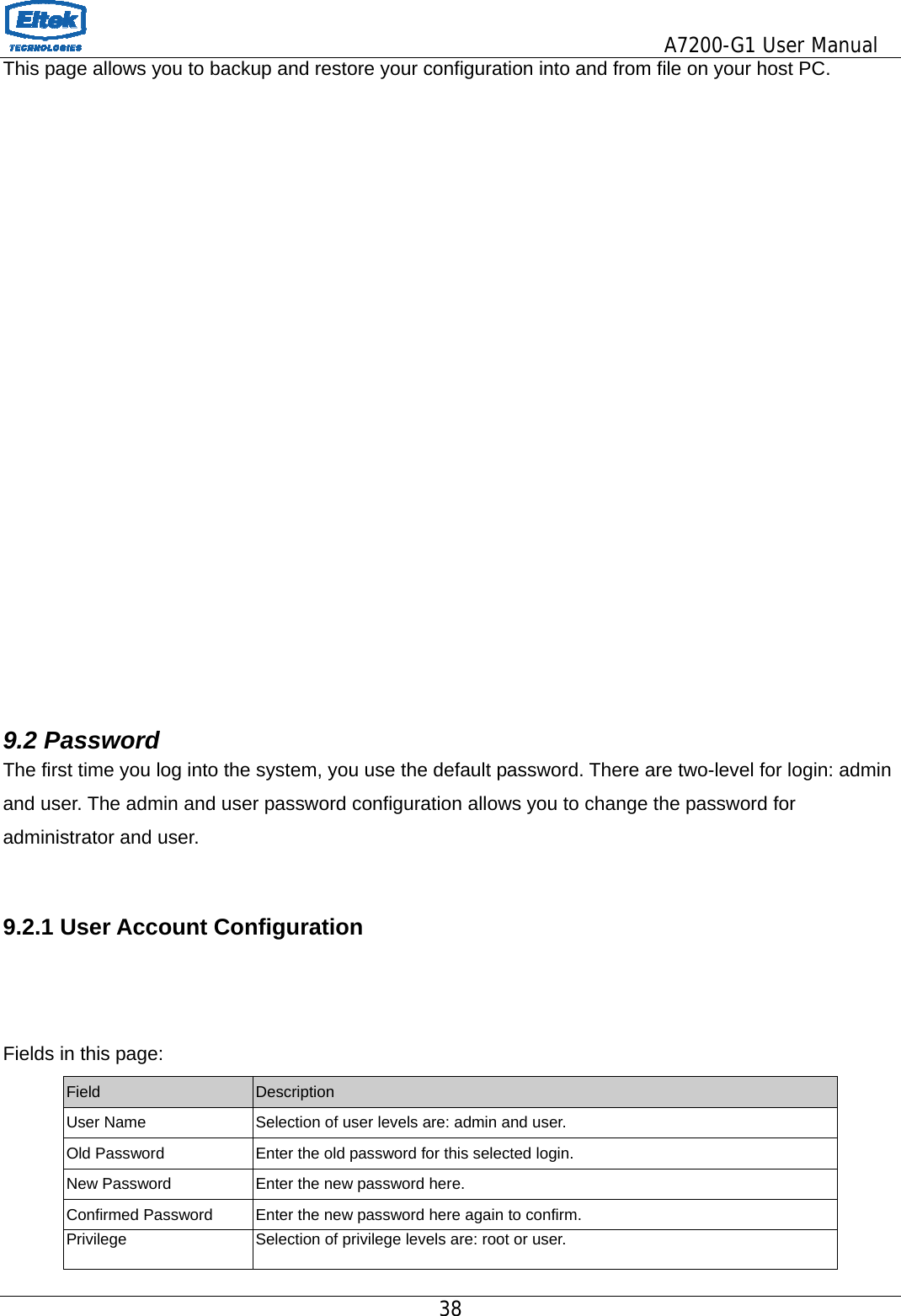
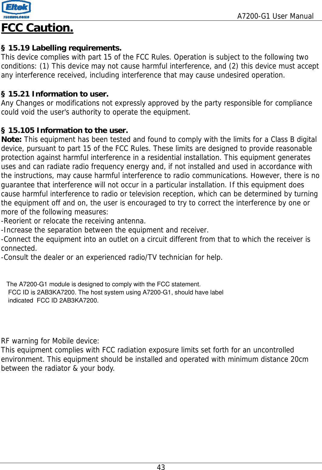
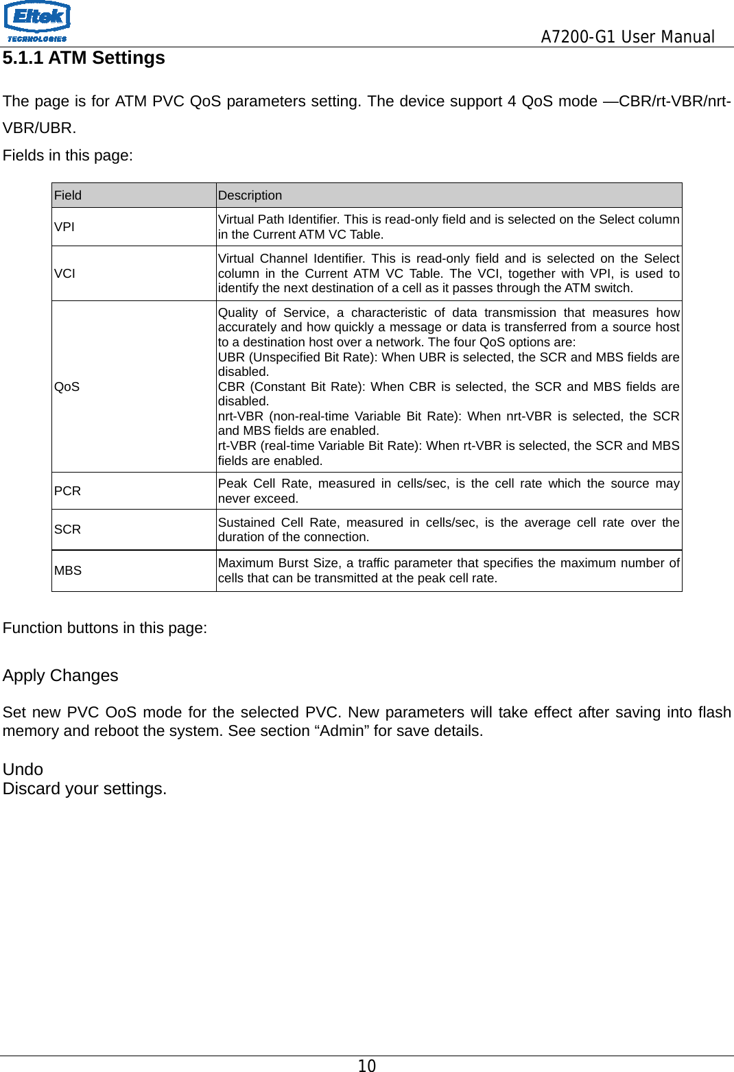
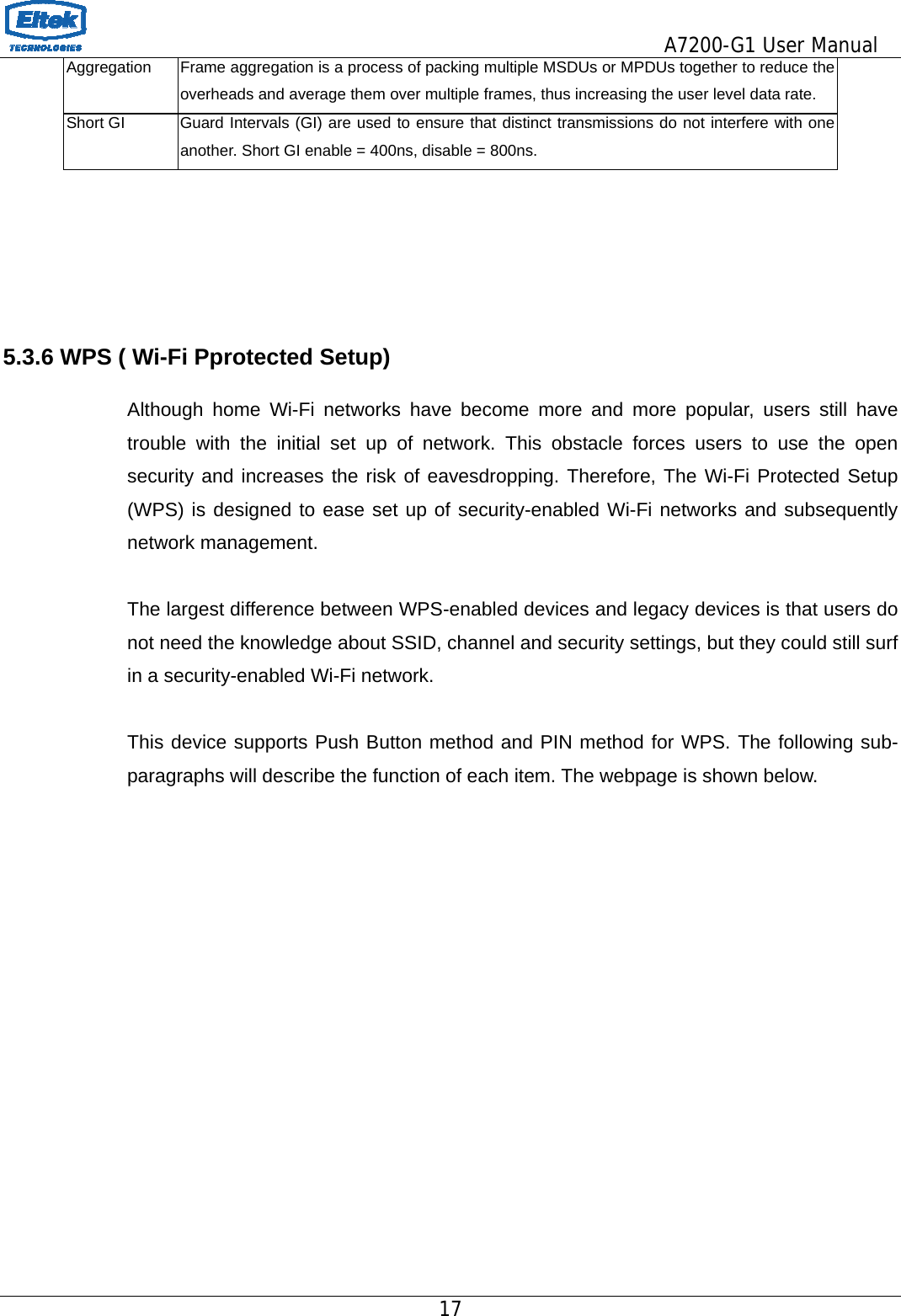
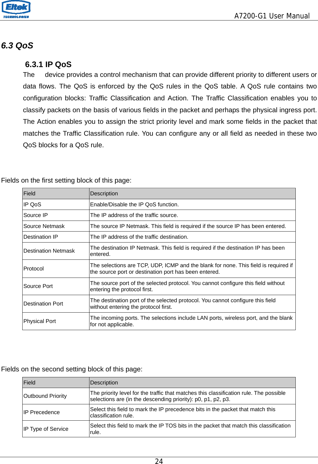
![This page displays the router’s current status and settings. This information is read-only except for the PPPoE/PPPoA channel for which user can connect/disconnect the channel on demand. Click the “Refresh” button to update the status Function buttons in this page: Connect / Disconnect The two buttons take effect only when PVC is configured as PPPoE/PPPoA mode. Click Connect/Disconnect button to connect/disconnect the PPP dial up link. 5. Setup 5.1 WAN Configuration There are three sub-menu for WAN configuration: [Channel Config], [ATM Settings] Channel Config modem/router supports 8 ATM Permanent Virtual Channels (PVCs). There are mainly three operations for each of the PVC channels: add, delete and modify. And there are several channel modes to be selected for each PVC channel. For each of the channel modes, the setting is quite different accordingly. Please refer to the section – Channel Mode Configuration for further details. Function buttons in this page: Add Click Add to complete the channel setup and add PVC channel into configuration. Modify Select an existing PVC channel by clicking the radio button at the Select column of the Current ATM VC Table before we can modify the PVC channel. After selecting PVC channel, we can modify the channel configuration at this page. Click Modify to complete the channel modification and apply to the configuration. Delete Select an existing PVC channel to be deleted by clicking the radio button at the Select column of the Current ATM VC Table. Click Delete to delete this PVC channel from configuration.](https://usermanual.wiki/Eltek-Technologies/A7200/User-Guide-2264581-Page-9.png)
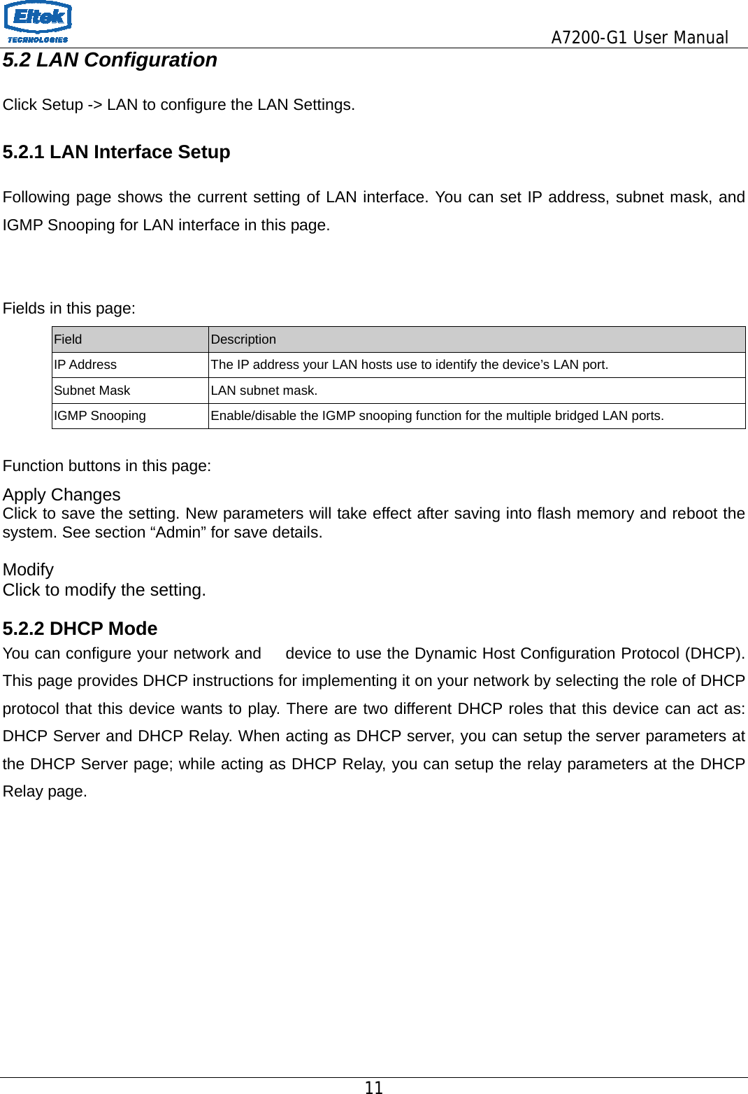
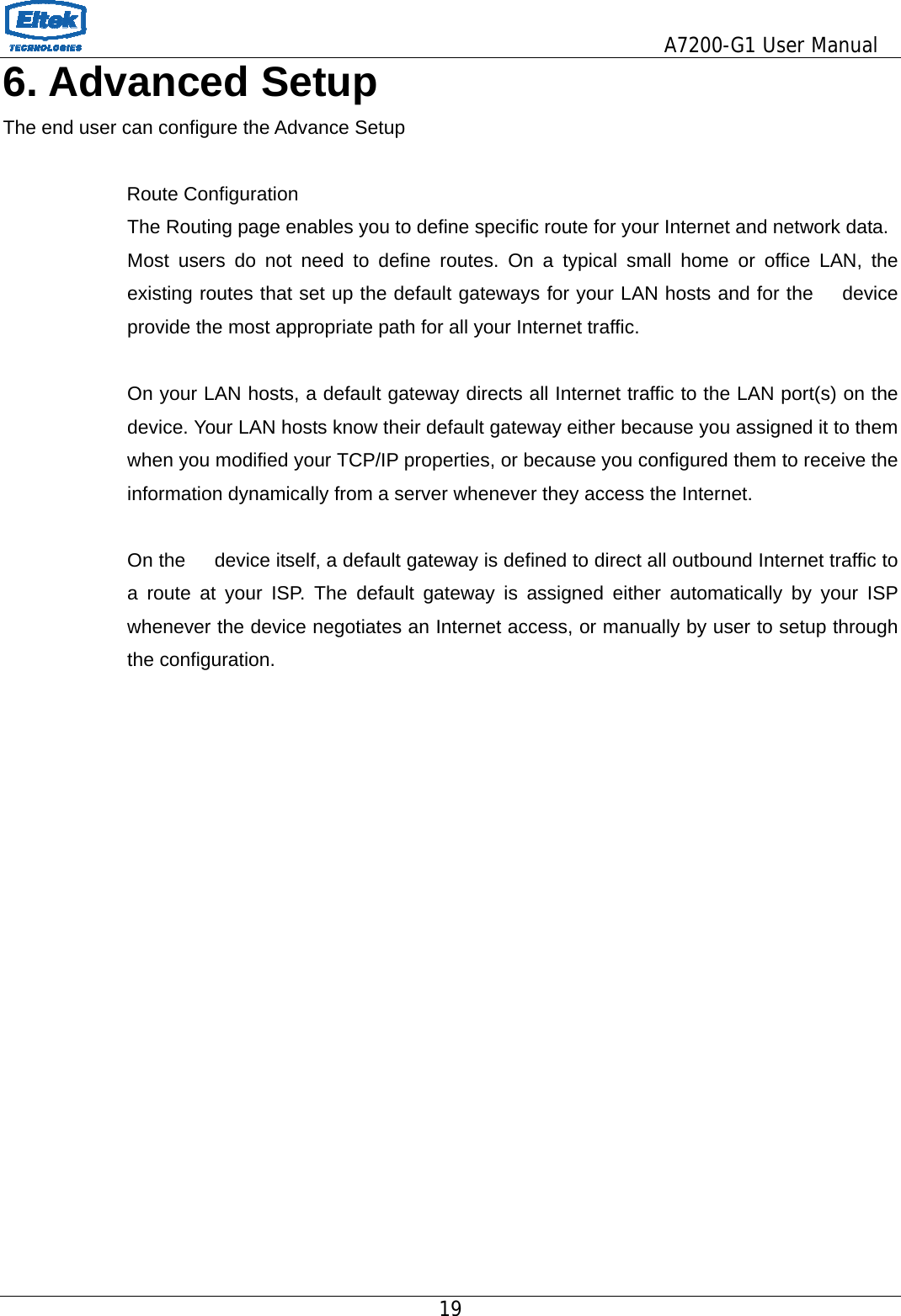
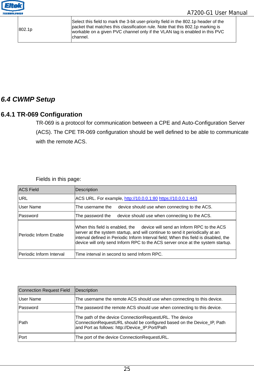
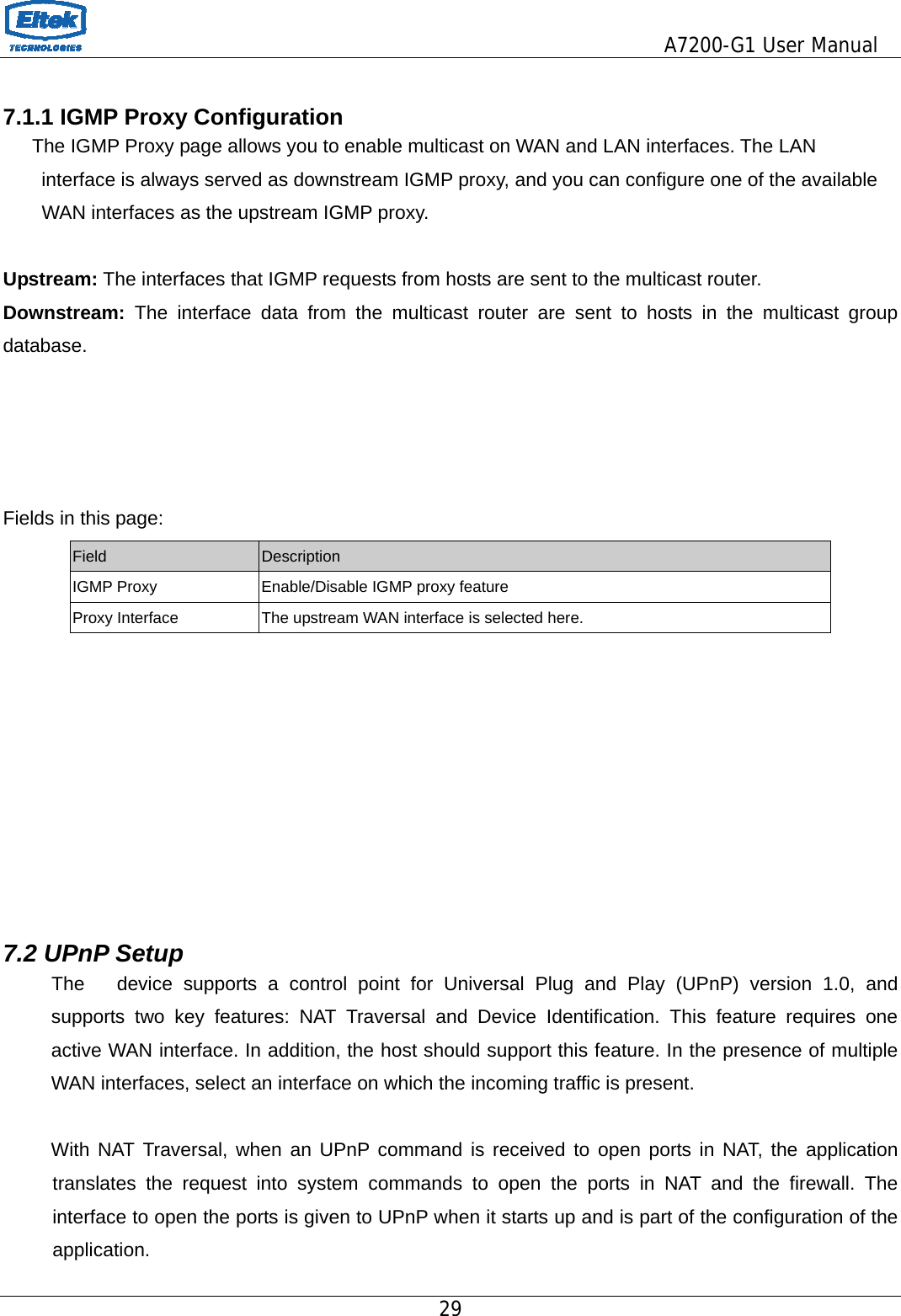
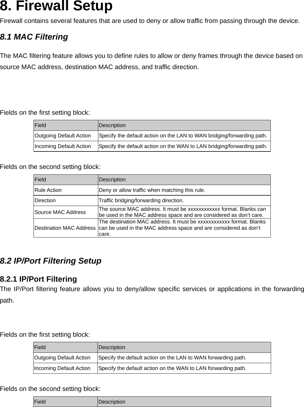
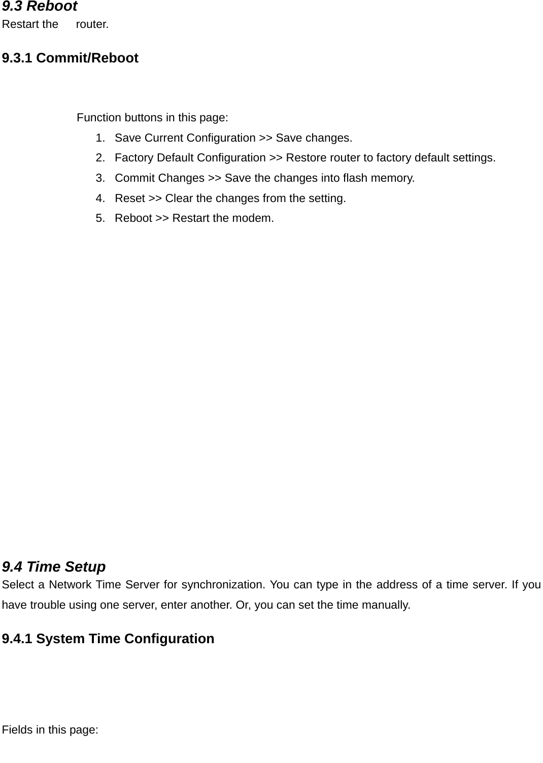
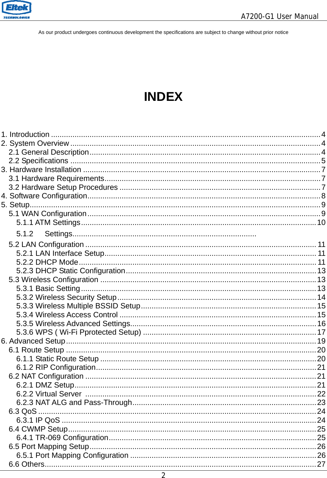
![A7200-G1 User Manual 27 6.6 Others 6.6.1 Bridge Setting You can enable/disable Spanning Tree Protocol and set MAC address aging time in this page. Fields in this page: Field Description Ageing Time Set the Ethernet address ageing time, in seconds. After [Ageing Time] seconds of not having seen a frame coming from a certain address, the bridge will time out (delete) that address from Forwarding DataBase (fdb). 802.1d Spanning Tree Enable/disable the spanning tree protocol 6.6.2 Client Limit Configuration This page is used to configure the capability of force how many devices can access to Internet! 6.6.3 Other Advanced Configuration Here you can set other miscellaneous advanced settings. Half Bridge: When the PPP Half Bridge is enabled the WAN IP address from the ISP is passed straight through the modem to the local client PC. Only one PC is able to access the Internet using half bridge mode as NAT is disabled. Half bridge mode can only be used when a single IP address has been assigned by the ISP, it is not suitable for services that provide multiple IP addresses. Half bridge mode is used when the use of NAT or NAPT is not desired and there is a single computer attached to the modem. When the half-bridged modem is used in conjunction with a router handling DHCP, only then multiple computers can connect to the Internet.](https://usermanual.wiki/Eltek-Technologies/A7200/User-Guide-2264581-Page-27.png)