Eltek Technologies R7121-L1 SIP Gateway User Manual 15 R7121 L1 UserMan
Eltek Technologies Ltd SIP Gateway 15 R7121 L1 UserMan
15_R7121-L1 UserMan
1
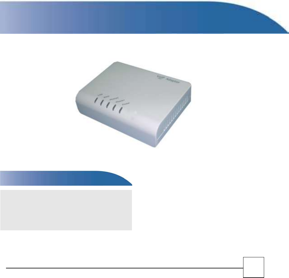
Eltek R7121-L1
Eltek R7141-L1
Eltek R7111-L1
Analogue Telephone Adapter
Note: default value are different based on different firmware version.
WAN IP Address: DHCP
LAN IP Address: http: 192.168.1.1
User Name: admin
Password: admin
User Manual
Default Login Detail

2
Table of Contents
TABLE OF CONTENTS ....................................................................................................................... 2
0.1 ABOUT THIS MANUAL 4
0.2 COPYRIGHT DECLARATIONS 4
0.3 TRADEMARKS 4
0.4 SAFETY INSTRUCTIONS 4
0.5 WARRANTY 4
INTRODUCE ..................................................................................................................................... 6
1.1 OVERVIEW 6
1.2 AUDIENCE 6
1.3 ACRONYMS TABLE 6
1.4 INTRODUCTION 6
1.5 FRONT PANEL LED INDICATORS & REAR PANELS 7
1.6 SPECIFICATION 9
INSTALLATION AND SETUP ........................................................................................................... 11
2.1 PACKAGE CONTENT 11
2.2HARDWARE INSTALLATION 11
2.3 QUICK START 15
2.4 WIZARD SETUP 17
NETWORK SETTING ....................................................................................................................... 21
3.1 WAN INTERFACE 21
3.2 LAN INTERFACE 27
3.3 NAT 28
VOIP SETTING (R7121-L1/R7141-L1/R7111-L1) ........................................................................... 30
4.1 SIP SETTING 32
4.2 PHONE 39
4.3 PHONE BOOK 44
4.4 PSTN LINE (R7141-L1 ONLY) 46
SECURITY ....................................................................................................................................... 47
5.1 FIREWALL 47

3
MAINTENANCE .............................................................................................................................. 50
6.1 SYSTEM 51
6.2 TOOLS 54
6.3 LOG 56
INFORMATION .............................................................................................................................. 58
IVR COMMAND ............................................................................................................................. 59
APPENDIX ...................................................................................................................................... 59
A - FAQ LIST 59
B - SCENARIO APPLICATION SAMPLES 60

4
Prefaces
0.1 About This Manual
This manual is designed to assist users in using Analogue Telephone Adapter R7121-L1/R7141-L1.
Information in this document has been carefully checked for accuracy; however, no guarantee is given as
to the correctness of the contents. The information contained in this document is subject to change
without notice.
0.2 Copyright Declarations
Copyright 2009 Telephony Corporation. All rights reserved. This publication contains information that is
protected by copyright. No part may be reproduced, transmitted, transcribed, stored in a retrieval system,
or translated into any language without written permission from the copyright holders.
0.3 Trademarks
Products and Corporate names appearing in this manual may or not be registered trademarks or
copyrights of their respective companies, and are used only for identification or explanation and to the
owners’ benefit, without to infringe.
0.4 Safety Instructions
The most careful attention has been devoted to quality standards in the manufacture of the Analogue
Telephone Adapter (R7121-L1/R7141-L1). Safety is a major factor in the design of every set. But, safety is
your responsibility too.
Use only the required power voltage. Power Input: AC 110V/220V, 1A, 50-60Hz
To reduce the risk of electric shock, do not disassemble this product. Opening or removing covers may
expose the R7121-L1/R7141-L1 to hazardous voltages. Incorrect reassembly can cause electric shock
when this product is subsequently used.
Never push objects of any kind into the equipment through housing slots since they may touch
hazardous voltage points or short out parts those could result in a risk of electric shock. Never spill
liquid of any kind on the product. If liquid is spilled, please refer to the proper service personnel.
Use only Unshielded Twisted Pair (UTP) Category 5 Ethernet cable to RJ-45 port of the Analogue
Telephone Adapter (R7121-L1/R7141-L1).
0.5 Warranty
We warrant to the original end user (purchaser) that the SA series Analogue Telephone Adapter
(R7121-L1/R7141-L1) will be free from any defects in workmanship or materials for a period of one (1)
years from the date of purchase from the dealer. Please keep your purchase receipt in a safe place as it
serves as proof of date of purchase. During the warranty period, and upon proof of purchase, should the
product have indications of failure due to faulty workmanship and/or materials, we will, at our discretion,
repair or replace the defective products or components, without charge for either parts or labor, to
whatever extent we deem necessary to re-store the product to proper operating condition. Any
replacement will consist of a new or re-manufactured functionally equivalent product of equal value, and
will be offered solely at our discretion. This warranty will not apply if the product is modified, misused,
tampered with, damaged by an act of God, or subjected to abnormal working conditions. The warranty
does not cover the bundled or licensed software of other vendors. Defects which do not significantly affect
the usability of the product will not be covered by the warranty. We reserve the right to revise the manual
and online documentation and to make changes from time to time in the contents hereof without
obligation to notify any person of such revision or changes.

5
Note
Repair or replacement, as provided under this warranty, is the exclusive remedy of the purchaser.
This warranty is in lieu of all other warranties, express or implied, including any implied warranty of
merchantability or fitness for a particular use or purpose. We shall in no event be held liable for
indirect or consequential damages of any kind of character to the purchaser.
To obtain the services of this warranty, contact us for your Return Material Authorization number
(RMA). Products must be returned Postage Prepaid. It is recommended that the unit be insured when
shipped. Any returned products without proof of purchase or those with an out-dated warranty will be
repaired or replaced and the customer will be billed for parts and labor. All repaired or replaced
products will be shipped by us to the corresponding return address, Postage Paid. This warranty gives
you specific legal rights, and you may also have other rights that vary from country to country.
6
1
Introduce
R7121-L1/R7141-L1/R7111-L1 series are the low cost VoIP Solutions. This document describes the
usage of R7121-L1/R7141-L1/R7111-L1 (Analogue Telephone Adapter)
1.1 Overview
An Analogue Telephone Adapter, or R7121-L1/R7141-L1, is a device that allows one to connect a
normal PSTN telephone to the Internet in order to make or place telephone calls.
R7121-L1/R7141-L1 provides a direct analog interface for PSTN, PBX, fax machines, analog telephones,
and other devices that require an analog port.
1.2 Audience
This document is intended for system vendor who are using R7121-L1/R7141-L1 to build an Internet
telephony gateway or server application. It is assumed that the reader has the general knowledge of VoIP
applications and products.
1.3 Acronyms Table
Acronym:
Full Name:
Acronym:
Full Name:
API
Application Interface
CODEC
Coder / Decoder
ADC
Analog to Digital Converter
DC
Direct Current
DAC
Digital to Analog Converter
DHCP
Dynamic Host Configuration Protocol
DDNS
Dynamic Domain Name System
DNS
Domain Name System
DTMF
Dual Tone Multi Frequency
MAC
Media Access Control
FXS
Foreign Exchange Station
NAT
Network Address Translation
WAN
Wide Area Network
PPTP
Point-to-Point Tunneling Protocol
NTP
Network Time Protocol
RTCP
Real-Time Transport Control
Protocol (also known as RTP control
protocol)
RTP
Real-Time Transport Protocol
SLIC
Subscriber Line Interface Circuit
SIP
Session Initiation Protocol
URI
Uniform Resource Identifier
STUN
Simple Traversal of UDP through
NATs
UDP
User DSR-100gram Protocol
TCP
Transmission Control Protocol
VoIP
Voice Over Internet Protocol
1.4 Introduction
This Analogue Telephone Adapter (R7121-L1/R7141-L1/R7111-L1) provides a total solution for
integrating voice-data network and PSTN.
The R7121-L1 Analogue Telephone Adapter (R7121-L1) support SIP VoIP Protocol.The R7121-L1
Analogue Telephone Adapter (R7121-L1) allows 1~2 lines analog voice and fax communication over a
traditional data communications/data networking digital Internet.
7
Model
FXO Port(PSTN)
FXS Port
WAN Port
LAN Port
RJ-11 port
SIP
R7121-L1
0
2
1
1
2
The R7141-L1 Analogue Telephone Adapter (R7141-L1) support SIP VoIP Protocol. The R7141-L1
Analogue Telephone Adapter (R7141-L1) allows 1~2 lines analog voice and fax communication over a
traditional data communications/data networking digital Internet.
Model
FXO Port(PSTN)
FXS Port
WAN Port
LAN Port
RJ-11 port
SIP
R7141-L1
1
1
1
1
2
The R7111-L1 Analogue Telephone Adapter (R7111-L1) support SIP VoIP Protocol.The R7111-L1
Analogue Telephone Adapter (R7111-L1) allows 1~2 lines analog voice and fax communication over a
traditional data communications/data networking digital Internet.
Model
FXO Port(PSTN)
FXS Port
WAN Port
LAN Port
RJ-11 port
SIP
R7121-L1
0
1
1
1
1
1.5 Front Panel LED Indicators & Rear Panels
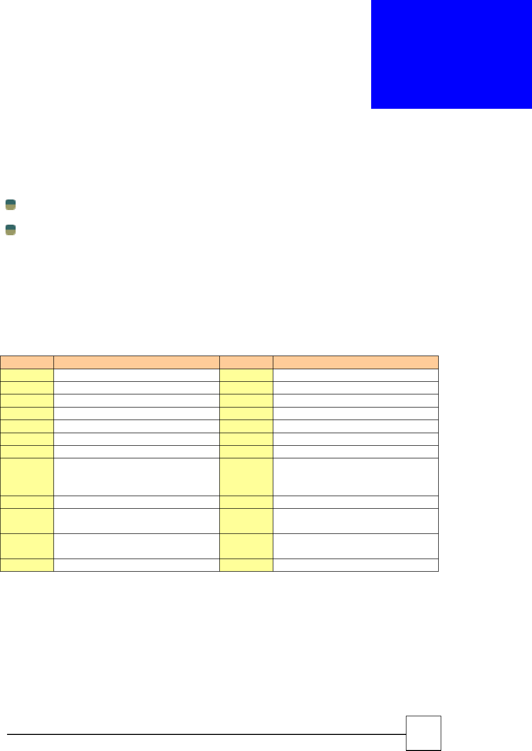
R7121-L1
------------------------------------------------------------------------------------
LED State Description
------------------------------------------------------------------------------------
1. POWER On R7121-L1 is power ON
Off R7121-L1 is power Off
-------------------------------------------------------------------------------------
2. LAN port On LAN is connected successfully
Flashing Data is transmitting
Off Ethernet not connected to PC
-------------------------------------------------------------------------------------
3. WAN port On R7121-L1 network connection established
Flashing Data traffic on cable network
Off Waiting for network connection
-------------------------------------------------------------------------------------
4. FXS (Phone) Off Telephone Set is On-Hook
Flashing Ring Indication
On Telephone Set is Off-Hook
8
-------------------------------------------------------------------------------------
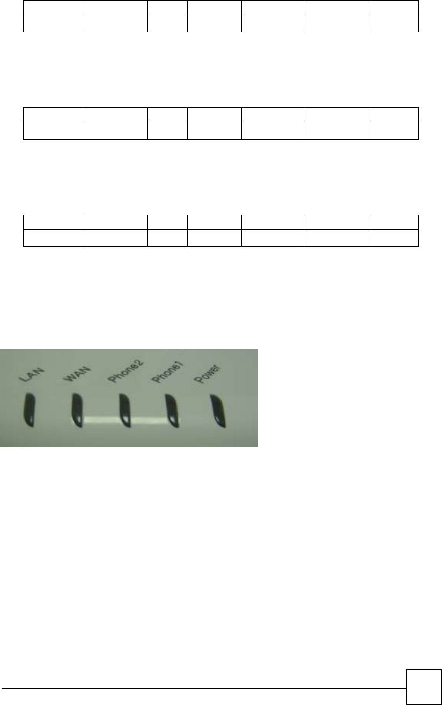
R7141-L1
------------------------------------------------------------------------------------
LED State Description
------------------------------------------------------------------------------------
1. POWER On R7141-L1 is power ON
Off R7141-L1 is power Off
-------------------------------------------------------------------------------------
2. LAN port On LAN is connected successfully
Flashing Data is transmitting
Off Ethernet not connected to PC
-------------------------------------------------------------------------------------
3. WAN port On R7141-L1network connection established
Flashing Data traffic on cable network
Off Waiting for network connection
-------------------------------------------------------------------------------------
4. FXS (Phone) Off Telephone Set is On-Hook
Flashing Ring Indication
On Telephone Set is Off-Hook
-------------------------------------------------------------------------------------
5. FXO (Line) Off Line is On-hook
On Line is In-Use
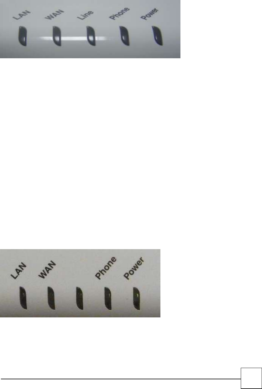
R7111-L1
------------------------------------------------------------------------------------
LED State Description
------------------------------------------------------------------------------------
1. POWER On R7111-L1 is power ON
Off R7111-L1 is power Off
-------------------------------------------------------------------------------------

9
2. LAN port On LAN is connected successfully
Flashing Data is transmitting
Off Ethernet not connected to PC
-------------------------------------------------------------------------------------
3. WAN port On R7111-L1 network connection established
Flashing Data traffic on cable network
Off Waiting for network connection
-------------------------------------------------------------------------------------
4. FXS (Phone) Off Telephone Set is On-Hook
Flashing Ring Indication
On Telephone Set is Off-Hook
1.6 Specification
VoIP Key Features:
Support SIP protocols: SIP Registration and Digest Authentication.
Smart VoIP call Dialing Book: VoIP call Book could provide any application VoIP call to any type
destination (Domain name/IP address, PSTN or PBX) or hunting number setting.
Voice channels status display: This function display each port status like as On-hook, Off-hook, calling
number callee’s number, talk duration, codec.
Telephony Specification:
Voice Codec: G.711(A-law /μ-law), G.729 AB, G.723 (6.3 Kbps / 5.3Kbps), G.726 (16,24,32,40 Kbps).
Call Waiting
Call Forward: Immediate /On Busy Forward / No Answer Forward
Speed Dial
Dial Plan With URL
Multi-Line Appearance
DTMF Relay : PCM/SIP INFO / Out-of-band DTMF Relay (RFC2833)
DND
Hot-Line
Jitter Buffer Control
DNS Server
FAX T.38
Session Timer
MWI (Message Waiting Indicator)
IP Specification:
SIP (RFC 3261) , SDP (RFC 2327), Symmetric RTP,
STUN (RFC3489), ENUM (RFC 2916), RTP Payload for DTMF Digits (RFC2833), Outbound Proxy
Support,
WAN: PPPoE client, DHCP client, Fix IP Address, PPTP/L2TP with WAN (Static、DHCP、PPPoE)
DDNS: DynDNS,TZO
QoS : IP TOS (IP Precedance) / DiffServ / SIP DSCP/RTP DSCP
VLAN
Call Features:
Volume : - 32 db ~ 30 db
VAD (Voice Activity Detection)
Caller ID Generation: DTMF CID / Bellcore CID / ETSI CID / BT CID / NTT CID

10
Peer to Peer Call by Dial Plan
Different Country Tone Table(Region)
G.168 Echo cancelation
Hook-Flash Timing
Call Transfer
Pulse Dial Detection
Auto Dial
Off-Hook Alarm
Configuration & Management:
Web-based Graphical User Interface
Remote management over the IP Network
Web Base firmware upgrade
Backup and Restore Configuration file
Different Account Login
Back to Factory Default
Time setting
Auto Provision(Auto config /Auto FW updrade)
Ping Test
Security (Firewall ):
IP Filter
MAC Filter
URL Filter
Port Filter
General Specification:
AC power : AC100V-240V, DC12V/1A, 50/60 Hz
Temperature: 0°C ~ 40°C (Operation)
Humidity: up to 90% non-condensing
Emission: FCC Part 15 Class B, CE Mark
RoHS Compliant
Dimension : 115 x 85 x 29 mm
Weight: 165 g
11
2
Installation and Setup
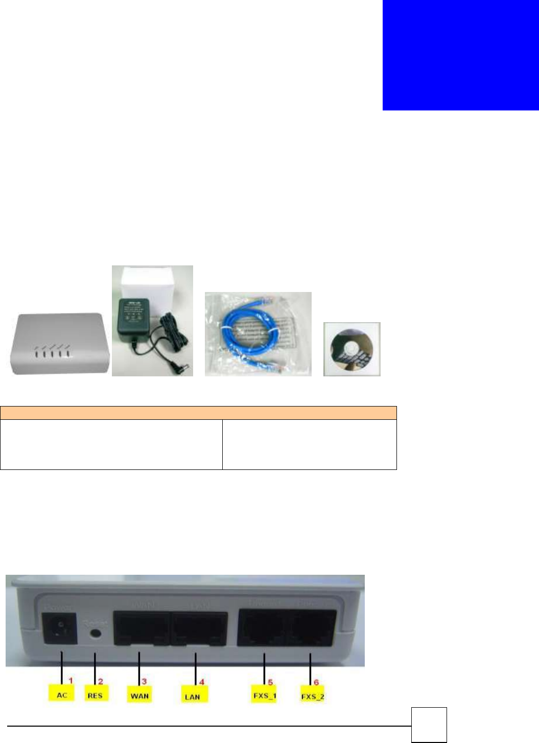
2.1 Package Content
Please check enclosed product and its accessories before installation. (Refer to the item number).
These contents are from pre-released product. The contents for the final product might change a little
bit.
Package
packet contents:
ATA (R7121-L1/ R7141-L1/R7111-L1)
RJ-45
AC Power Adapter (1A)
CD-Rom(User manual)
X1
X1
X1
X1
2.2Hardware Installation
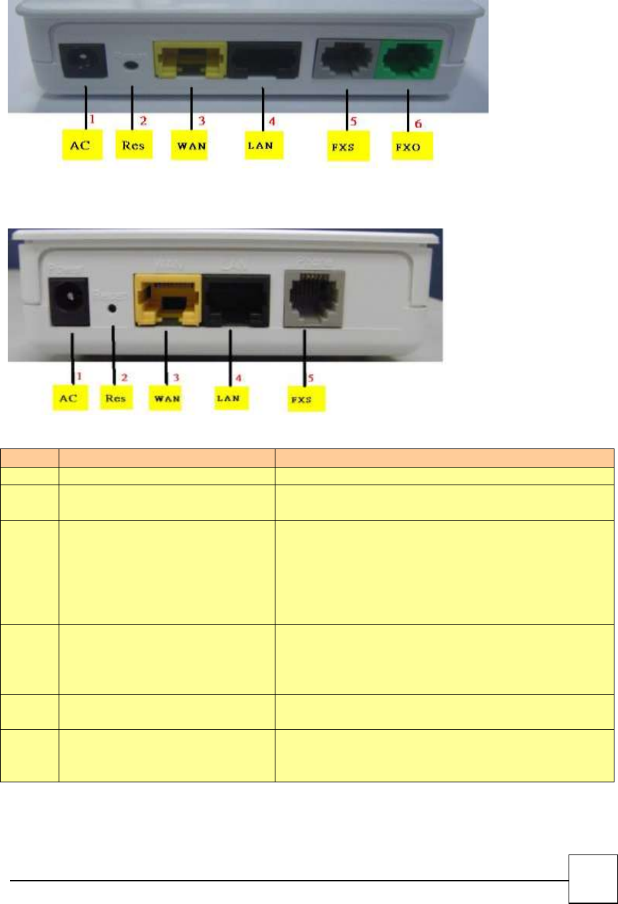
Port Description: DEMO Model R7121-L1
12
Port Description: DEMO Model R7141-L1
Port Description: DEMO Model R7111-L1
Item
Port
Description
1
AC power(DC in 12V)
A power supply cable is inserted
2
RES(Reset button)
Push this button until 3 seconds, and ATA will be set to
factory default configuration.
3
WAN(Wide Area Network)
Connect to the network with an Ethernet cable. This
port allows your ATA to be connected to an Internet
Access device, e.g. router, cable modem, ADSL modem,
through a networking cable with RJ-45 connectors used
on 10BaseT and 100BaseTX networks.
4
LAN(Local Area Network)
Connect to PC with Ethernet cable. 1 port allows your
PC or Switch/Hub to be connected to the ATA through a
networking cable with RJ-45 connectors used on
10BaseT and 100BaseTX networks.
5
FXS(Foreign Exchange Station)
FXS port can be connected to analog telephone sets or
Trunk Line of PBX.
6
PSTN(FXO)
Connect to PBX or CO line with RJ-11(Gray) analog line.
FXO port was connected to the extension port of a PBX
or directly connected to a PSTN line of carrier.
13
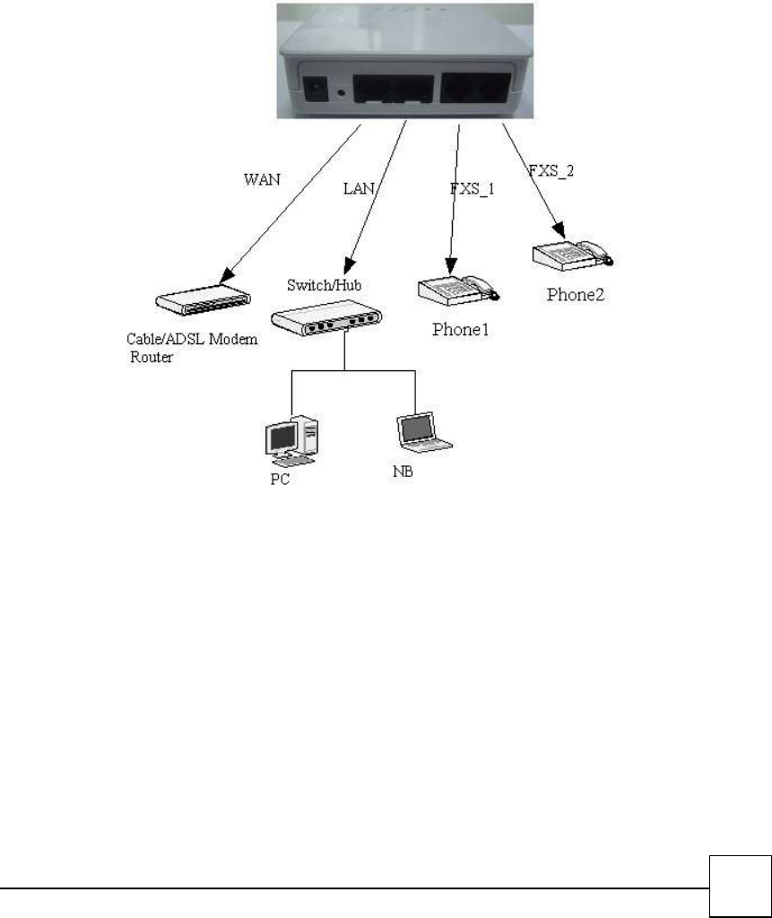
Installation:
1 Connect the 12V DC IN to the power outlet with power adaptor.
2 Connect FXO to PSTN.
3 Connect FXS to a telephone jack with the RJ-11 analog cable.
Connecting to a PC:
1 Connect the Ethernet cable (with RJ-45 connector) to any LAN port.
2 Connect the other end of the Ethernet cable to your PC’s installed network interface card (NIC).
Connecting to an External Ethernet Hub or Switch:
1 Connect the Ethernet cable (with RJ-45 connector) to WAN port.
2. Connect the other end of the Ethernet cable to DSL/Cable modem or the external Ethernet hub or
switch.
R7121-L1:
14
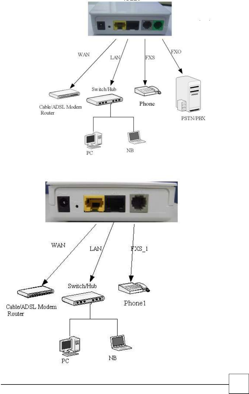
R7141-L1:
R7111-L1:
15
2.3 Quick Start
How to set your network environment?
R7121-L1/R7141-L1 default network environment:
For WAN:
Wan type: DHCP client
For LAN:
IP: 192.168.1.1
Subnet mask: 255.255.255.0
How to configure R7121-L1/R7141-L1/R7111-L1?
1. Configure your PC or NB to the same subnet with R7121-L1/R7141-L1/R7111-L1.
2. Use web browser (IE/Firefox) link to url: http://192.168.1.1 (If you connect to LAN port, link to url:
http://192.168.1.1 )
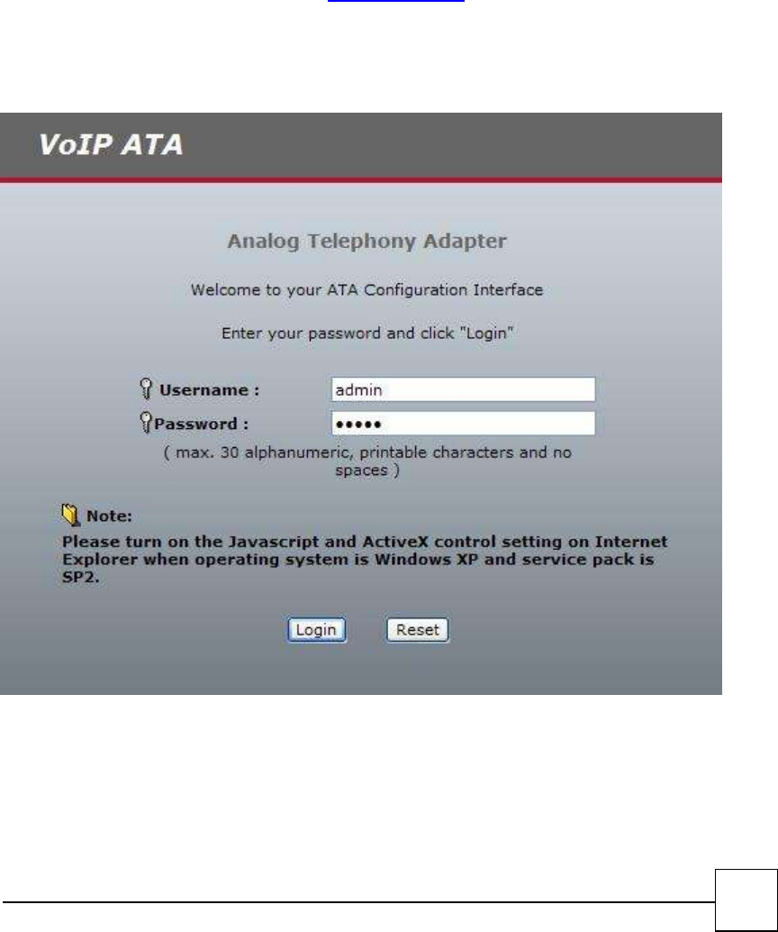
3. Login user name: admin
4. Login password: admin
5. Use this web configuration interface to configure all system functionality; firstly you should change
the WAN network environment to yours.
How to use VoIP?
1. Configure SIP user account to register your SIP proxy, use web configuration:
“SIP Settings” -> “Account Setting”
a. Port Phone Number
b. Port Authentication User Name
c. Port Authentication Password

16
d. Confirmed Password
2. Configure SIP registrar server and proxy server, use web configuration:
“SIP Settings” -> “Server Setting”
a. Registrar Server Address
b. Outbound Proxy Address
3. Make sure R7121-L1/R7141-L1/R7111-L1 has already registered to your proxy, and then you can
make a call
17
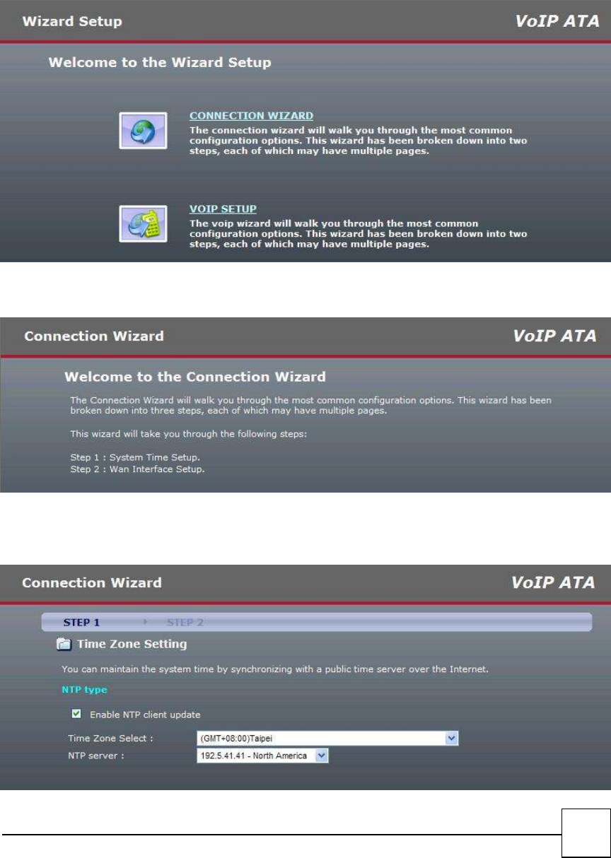
2.4 Wizard Setup
Wizard for Quick Setup ATA after finishing the authentication, the Main menu will display 2 parts of
configuration, please click “Connection wizard” to enter quick start:
Step 1. Connection wizard
Step 2. Welcome to the VOIP ATA Connection Wizard
Step 3. Time Zone Setup
18
Time Zone Select : Choose your time zone
NTP Server : Select NTP server.
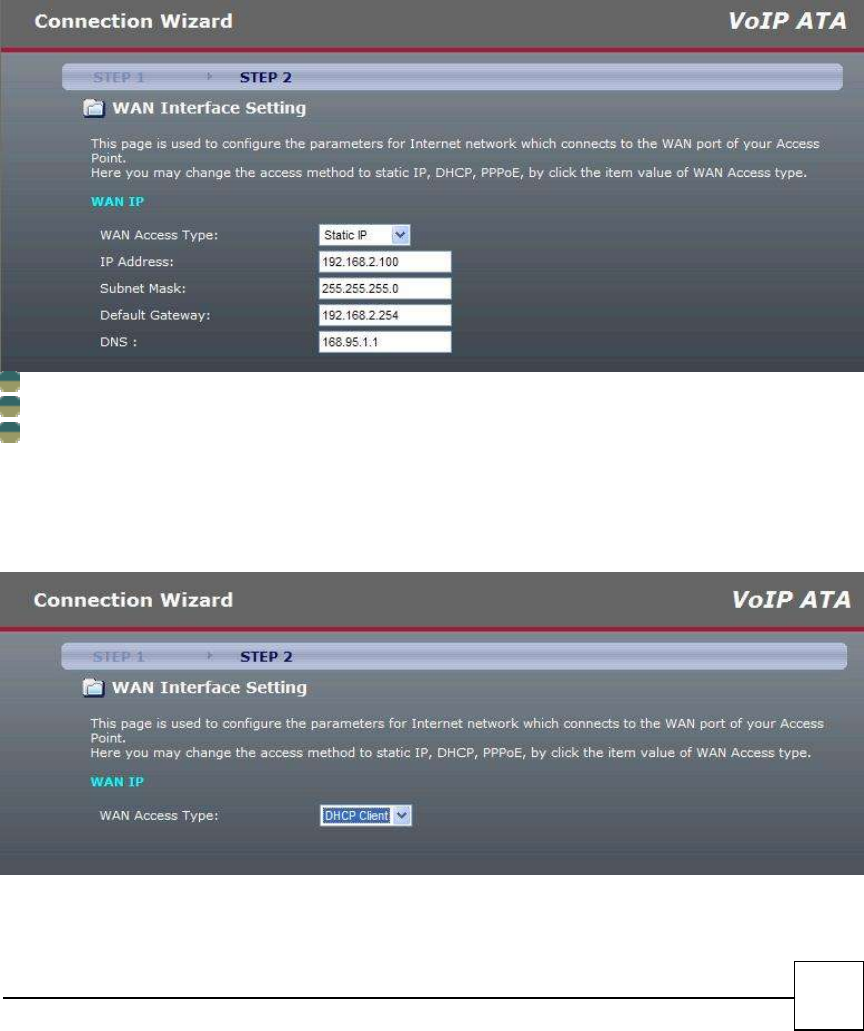
Step 4. WAN Port Type Setup:
For most users, Internet access is the primary application. The ATA support the WAN interface for
Internet access and remote access. The following sections will explain more details of WAN Port Internet
access and broadband access setup. When you click “WAN Port Type Setup” from within the Wizard
Setup, the following setup page will be show.
Three methods are available for Internet Access:
Fixed IP User: If you are a leased line user with a fixed IP address, fill out the following items with
the information provided by your ISP.
WAN IP Address: check with your ISP provider
Subnet mask: check with your ISP provider
Default Gateway: check with your ISP provider
DHCP Client (Dynamic IP):
Get WAN IP Address automatically
ADSL Dial-Up User (PPPoE Enable)
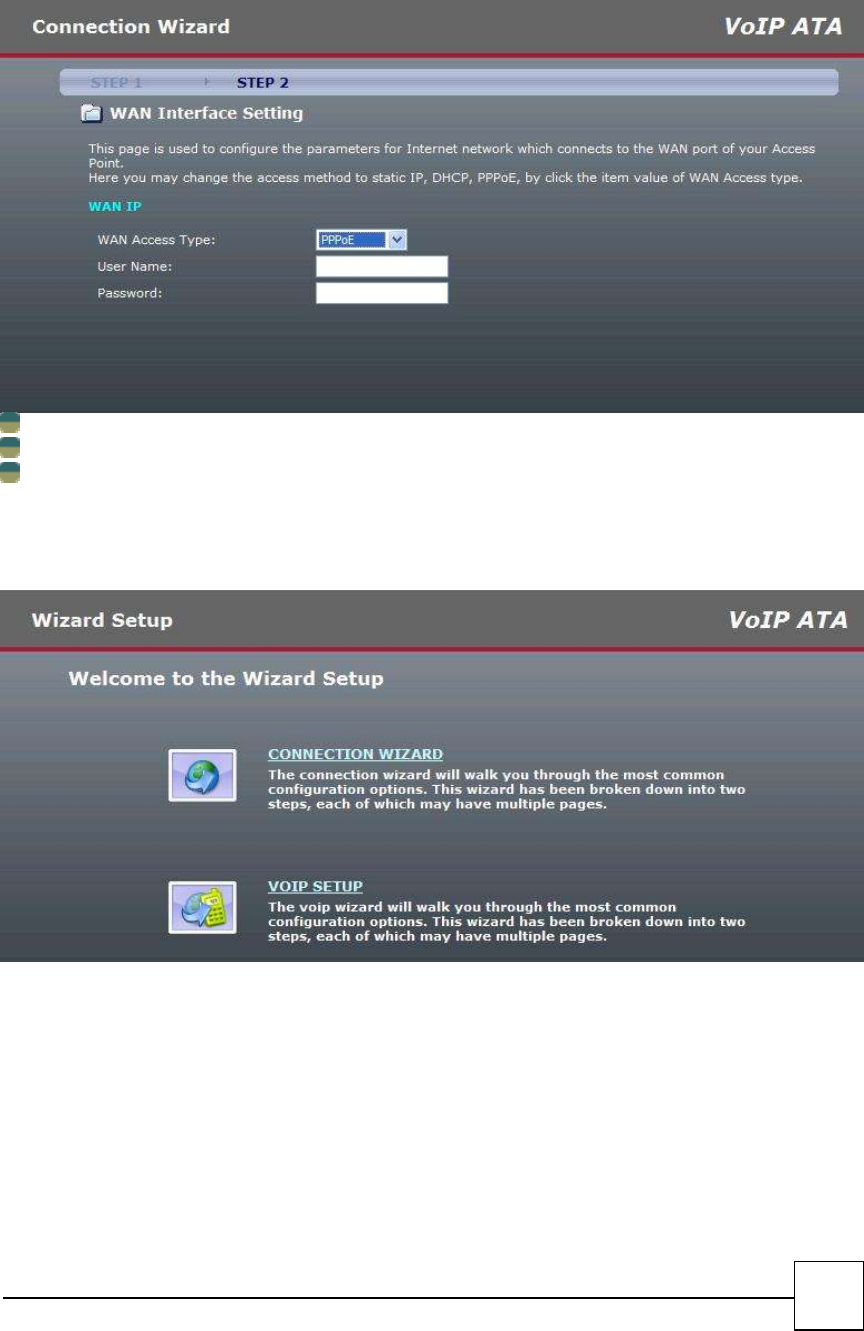
19
Some ISPs provide DSL-based service and use PPPoE to establish communication link with end-users. If
you are connected to the Internet through a DSL line, check with your ISP to see if they use PPPoE. If they
do, you need to select this item.
PPPoE User Name: Enter User Name provided by your ISP
PPPoE Password: Enter Password provided by your ISP.
Confirmation Password: Enter Password to confirm again.
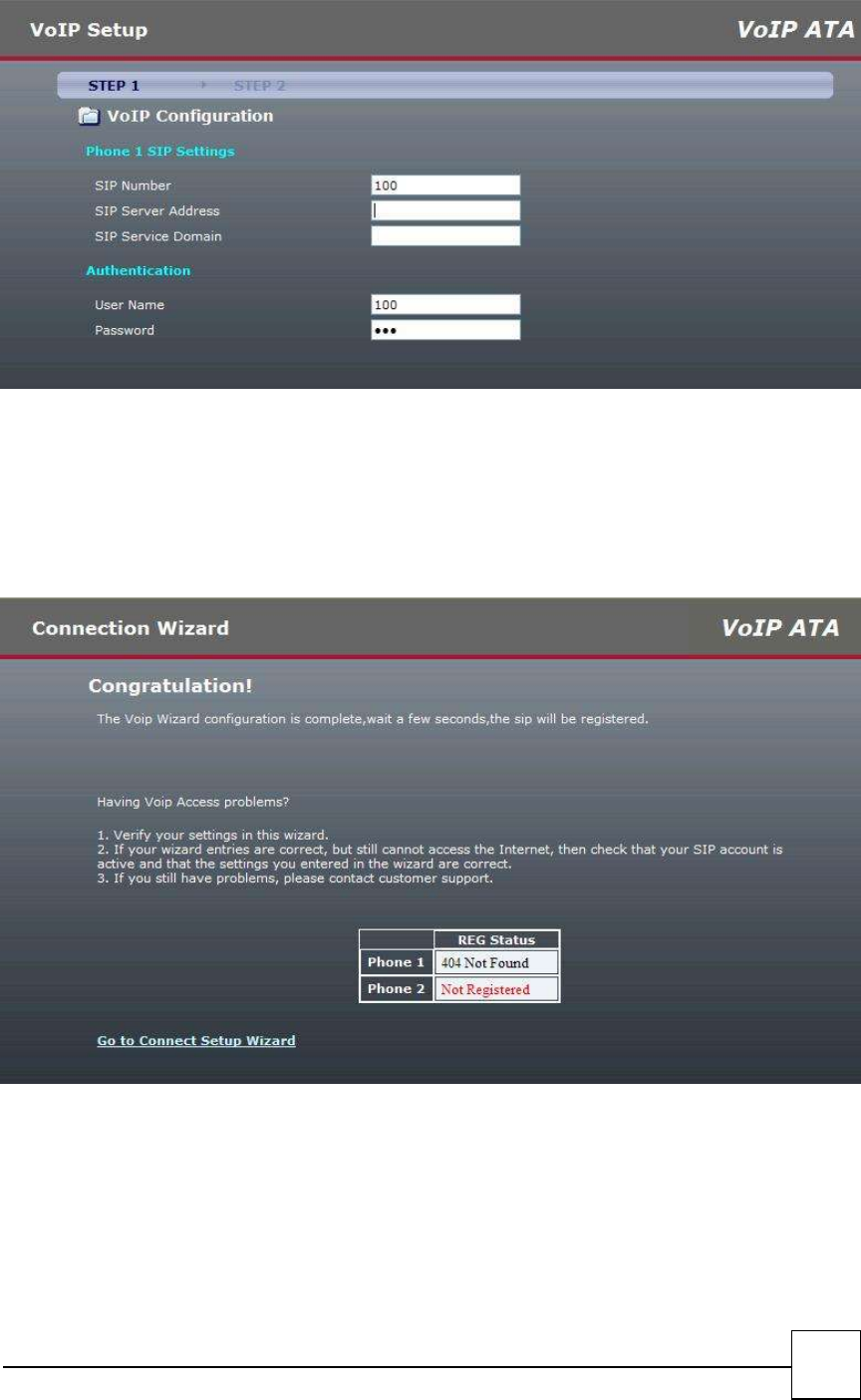
Step 6.Voip Setup
20
□SIP Number: you need to input the User Name get from your ISP.
□SIP Server add: you need to input the Proxy add get from your ISP.
□SIP Server Domain: you need to input the SIP Domain get from your ISP.
□User Name: you need to input the Register User Name get from your ISP.
□Password: you need to input the Register Password get from your ISP.
Step 7. Finishing the Wizard Setup

21
3
Network Setting
WAN Interface
LAN Interface
NAT
3.1 WAN Interface
WAN (Wide Area Network) is a network connection connecting one or more LANs together over some
distance. For example, the means of connecting two office buildings separated by several kilometers
would be referred to as a WAN connection. The size of a WAN and the number of distinct LANs connected
to a WAN is not limited by any definition. Therefore, the Internet may be called a WAN.
WAN Settings are settings that are used to connect to your ISP (Internet Service Provider). The WAN
settings are provided to you by your ISP and often times referred to as "public settings". Please select the
appropriate option for your specific ISP.
For most users, Internet access is the primary application. R7121-L1/R7141-L1/R7111-L1 supports the
WAN interface for internet access and remote access. The following sections will explain more details of
WAN Port Internet access and broadband access setup. When you click “WAN Setting”, the following
setup page will be shown. Three methods are available for Internet Access.
Static IP
DHCP
PPPoE
PPTP with WAN (Static、DHCP、PPPoE)
22
23
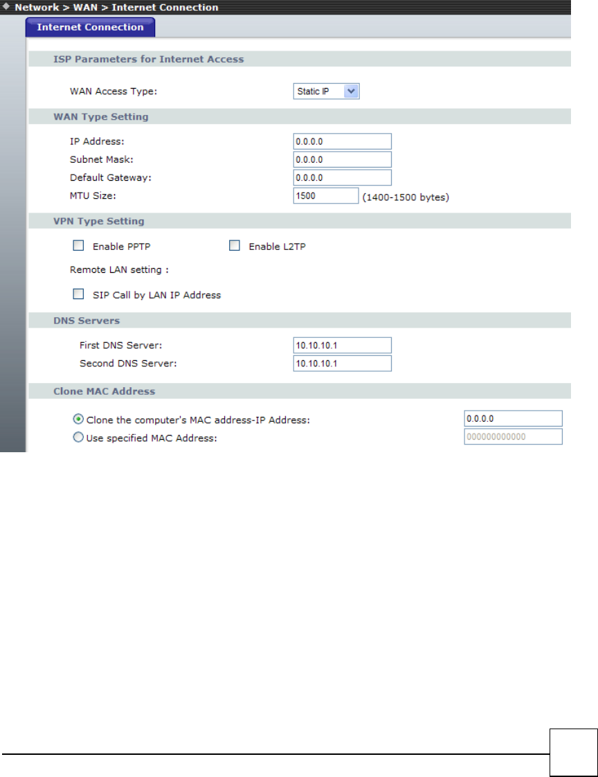
Static IP
If you are a leased line user with a fixed IP address, enter in the IP address, subnet mask, gateway
address, and DNS (domain name server) address(es) provided to you by your ISP. Each IP address entered
in the fields must be in the appropriate IP form, which are four IP octets separated by a dot (x.x.x.x). The
Router will not accept the IP address if it is not in this format.
Example: 168.95.1.1
■IP Address: Check with your ISP provider.
■Subnet Mask: Check with your ISP provider.
■Default Gateway: Check with your ISP provider.
24
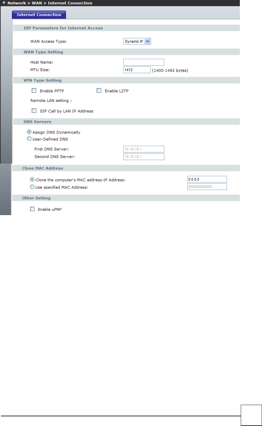
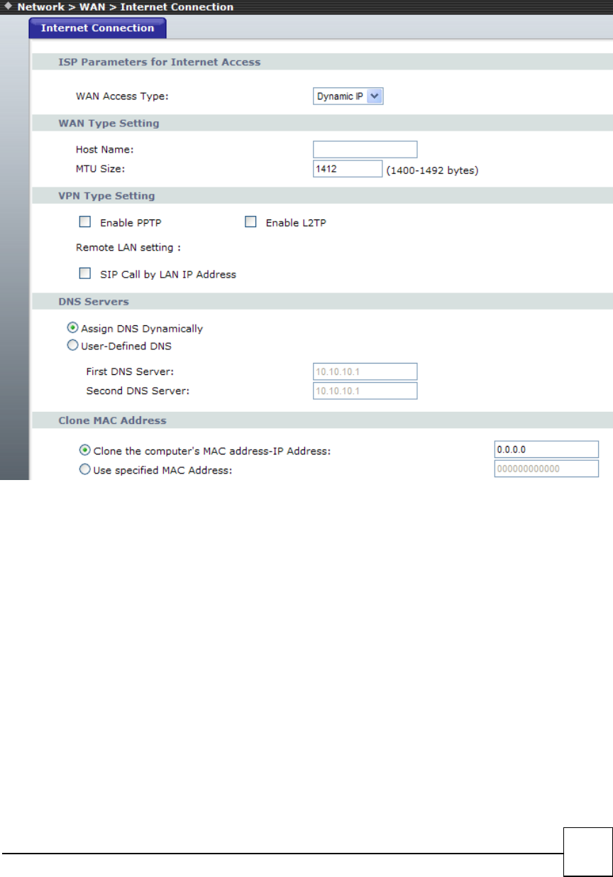
DHCP client
Dynamic Host Configuration Protocol (DHCP), Dynamic IP (Get WAN IP Address automatically). If you
are connected to the Internet through a Cable modem line, then a dynamic IP will be assigned.
Note: WAN port gets the IP Address, Subnet Mask and default gateway IP address automatically, if DHCP
client is successful.
25
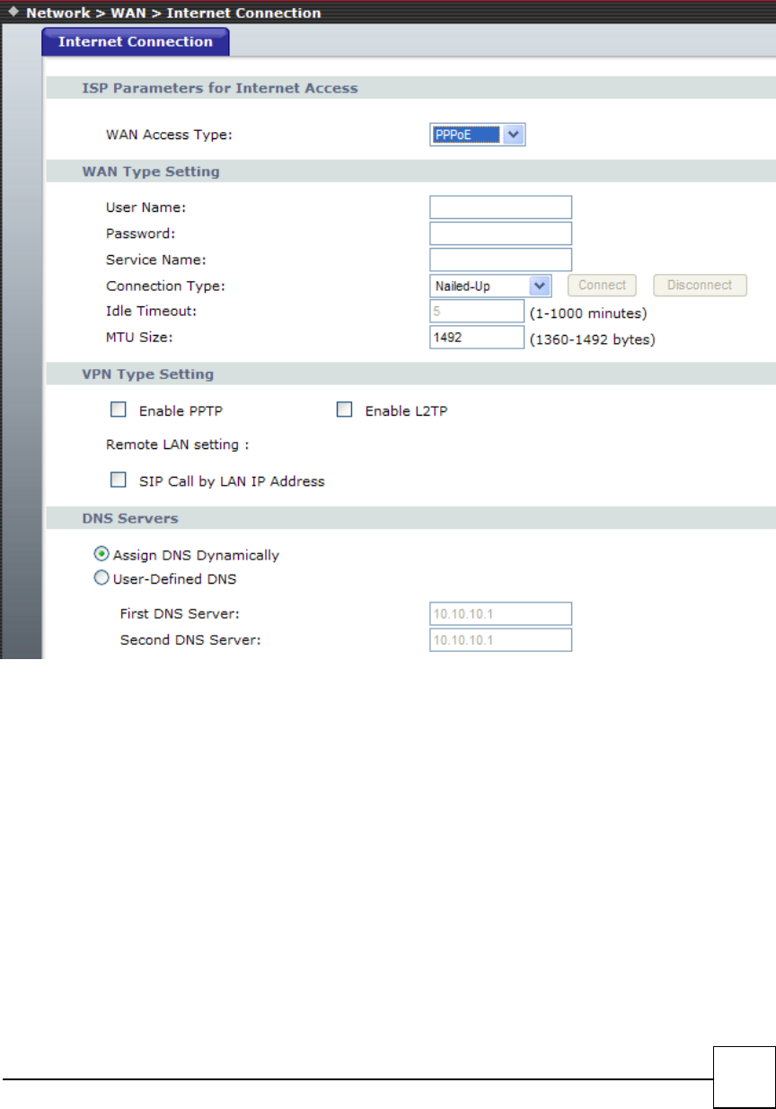
PPPoE
Point-to-Point Protocol over Ethernet (PPPoE). Some ISPs provide DSL-based services and use PPPoE to
establish communication link with end-users. If you are connected to the Internet through a DSL line,
check with your ISP to see if they use PPPoE. If they do, you need to make sure the following items, PPPoE
User name: Enter username provided by your ISP. PPPoE Password: Enter password provided by your ISP.
26
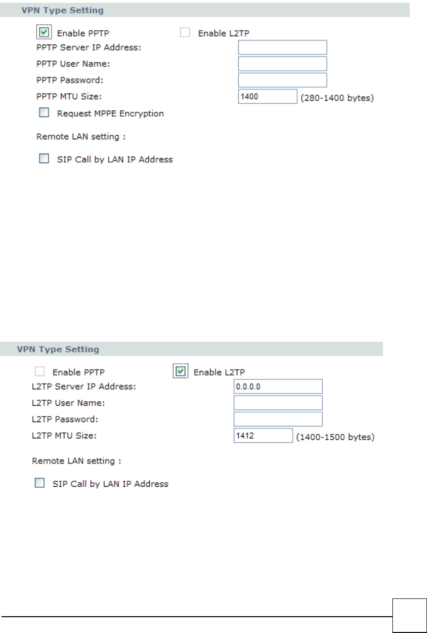
PPTP with WAN (Static、DHCP、PPPoE)
Some ISPs provide DSL-based service and use PPTP with Static, DHCP or PPPoE to establish communication
link with end-users.
■PPTP Server IP Address: check with your VPN /PPTP Server provider
■PPTP User Name: PPTP Dial-in account
■PPTP Password: PPTP Dial-in Password
■PPTP MTU Size
■Request MPPE Encryption
■Remote LAN setting: select SIP Call by LAN IP Address or not
L2TP with WAN (Static、DHCP、PPPoE)
Some ISPs provide DSL-based service and use L2TP with Static, DHCP or PPPoE to establish communication
link with end-users.
■L2TP Server IP Address: check with your VPN /PPTP Server provider
■L2TP User Name: L2TP Dial-in account
■L2TP Password: L2TP Dial-in Password
■L2TP MTU Size
■Request MPPE Encryption
■Remote LAN setting: select SIP Call by LAN IP Address or not
27
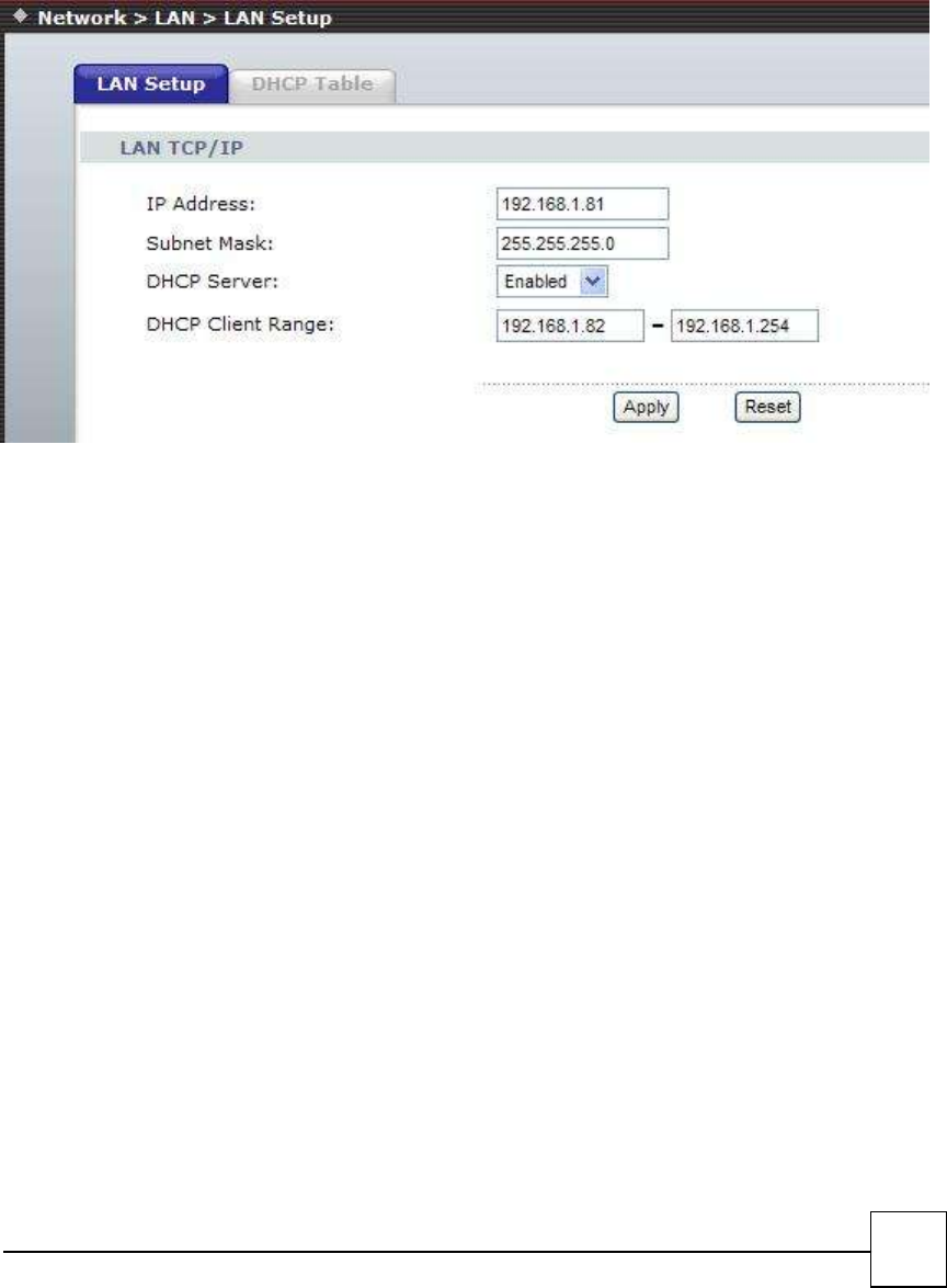
3.2 LAN Interface
These are the IP settings of the LAN (Local Area Network) interface for the device. These settings may
be referred to as "private settings". You may change the LAN IP address if needed. The LAN IP address is
private to your internal network and cannot be seen on the Internet. The default IP address is 192.168.1.1
with a subnet mask of 255.255.255.0.
LAN is a network of computers or other devices that are in relatively close range of each other. For
example, devices in a home or office building would be considered part of a local area network.
□LAN IP Address: Assign the IP address of LAN server, default is 192.168.1.1
□Subnet Mask: Select a subnet mask from the pull-down menu, default is 255.255.255.0.
DHCP Server Setting
DHCP stands for Dynamic Host Control Protocol. The DHCP server gives out IP addresses when a device
is starting up and request an IP address to be logged on to the network. The device must be set as a DHCP
client to "Obtain the IP address automatically". By default, the DHCP Server is enabled in the unit. The
DHCP address pool contains the range of the IP address that will automatically be assigned to the clients
on the network.
DHCP client computers connected to the unit will have their information displayed in the DHCP Client
List table. The table will show the Type, Host Name, IP Address, MAC Address, Description, and Expired
Time of the DHCP lease for each client computer.
DHCP Server is a useful tool that automates the assignment of IP addresses to numbers of computers in
your network. The server maintains a pool of IP addresses that you use to create scopes. (A DHCP scope is
a collection of IP addresses and TCP/IP configuration parameters that are available for DHCP clients to
lease.) Then, the server automatically allocates these IP addresses and related TCP/IP configuration
settings to DHCP-enabled clients in the network. The DHCP Server leases the IP addresses to clients for a
period that you specify when you create a scope. A lease becomes inactive when it expires. Through the
DHCP Server, you can reserve specific IP addresses permanently for hardware devices that must have a
static IP address (e.g., a DNS Server).
An advantage of using DHCP is that the service assigns addresses dynamically. The DHCP Server returns
addresses that are no longer in use to the IP addresses pool so that the server can reallocate them to
other machines in the network. If you disable this DHCP, you would have to manually configure IP for new
computers, keep track of IP addresses so that you could reassign addresses that clients aren't using, and
reconfigure computers that you move from one subnet to another. The DHCP Static MAP table lists all
28
MAC and IP address which are active now.
When you enable the DHCP server,
□Assigned DHCP IP Address: Enter the starting IP address for the DHCP server’s IP assignment and the
ending IP address for the DHCP server’s IP assignment.
□DHCP IP Lease Time - Assign the length of time for the IP lease, default setting is 86400 seconds.
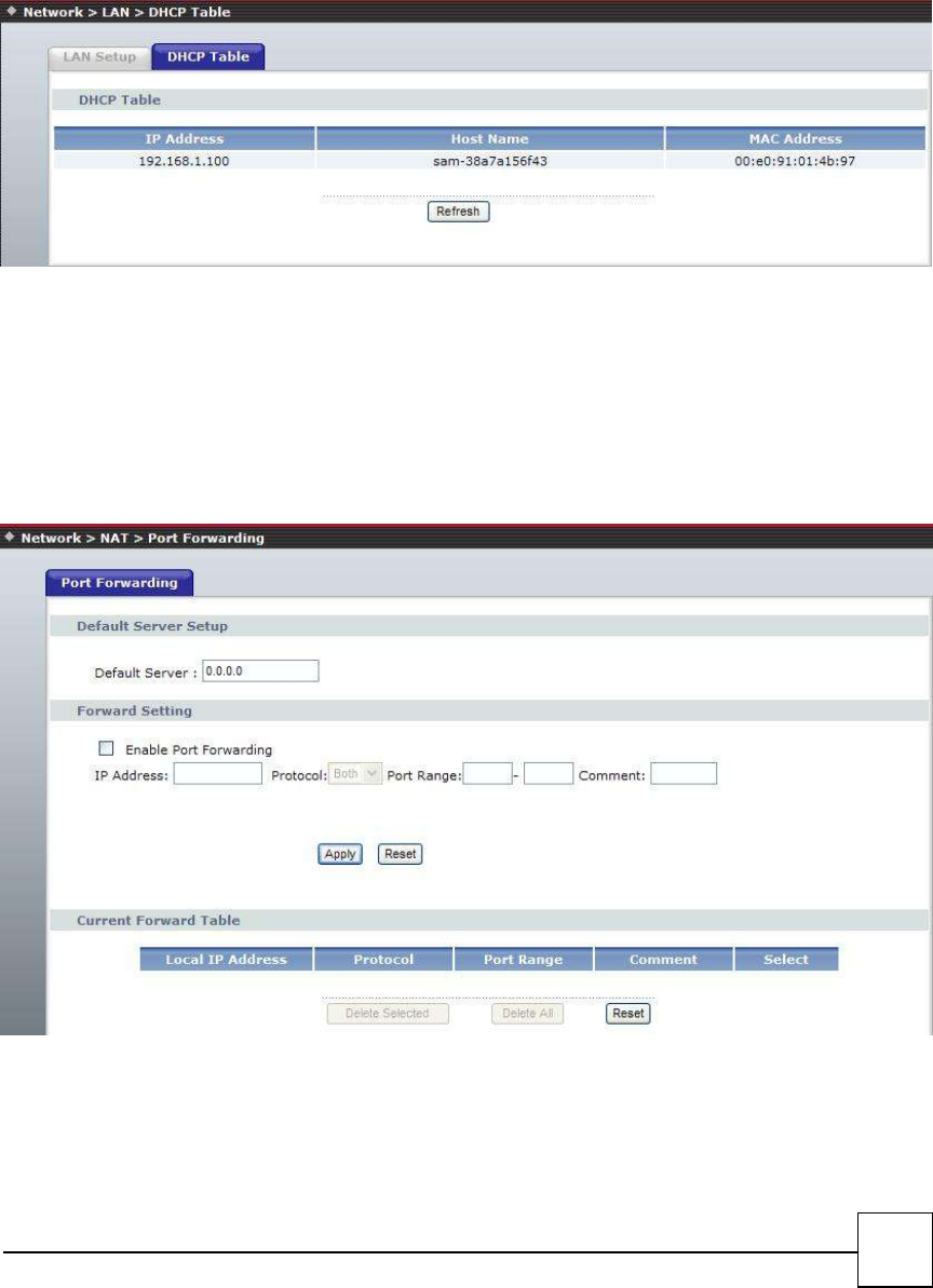
DHCP Table
3.3 NAT
A Demilitarized Zone is used to provide Internet services without sacrificing unauthorized access to its
local private network. Typically, the DMZ host contains devices accessible to Internet traffic, such as Web
(HTTP ) servers, FTP servers, SMTP (e-mail) servers and DNS servers.
DMZ - In computer networks, a DMZ (Demilitarized Zone) is a computer host or small network inserted
as a "neutral zone" between a company's private network and the outside public network. It prevents
outside users from getting direct access to a server that has company data. Think of DMZ as the front yard
of your house. It belongs to you and you may put some things there, but you would put anything valuable
inside the house where it can be properly secured. Setting up a DMZ is very easy. If you have multiple

29
computer s, you can choose to simply place one of the computers between the Internet connection and
the firewall.
If you have a computer that cannot run Internet applications properly from behind the device, then you
can allow the computer to have unrestricted Internet access. Enter the IP address of that computer as a
DMZ host with unrestricted Internet access. Adding a client to the DMZ may expose that computer to a
variety of security risks; so only use this option as a last resort.
Port Forwarding
Entries in this table allow you to automatically redirect common network services to a specific machine
behind the NAT firewall. These settings are only necessary if you wish to host some sort of server like a
web server or mail server on the private local network behind your Gateway's NAT firewall.
30
4
VOIP Setting (R7121-L1/R7141-L1/R7111-L1)
SIP is a request-response protocol, dealing with requests from clients and responses from servers.
Participants are identified by SIP URLs. Requests can be sent through any transport protocol. SIP
determines the end system to be used for the session, the communication media and media parameters,
and the called party's desire to engage in the communication. Once these are assured, SIP establishes call
parameters at either end of the communication, and handles call transfer and termination.
SIP Setting
Phone
Phone book
PSTN Line (R7141-L1 only)
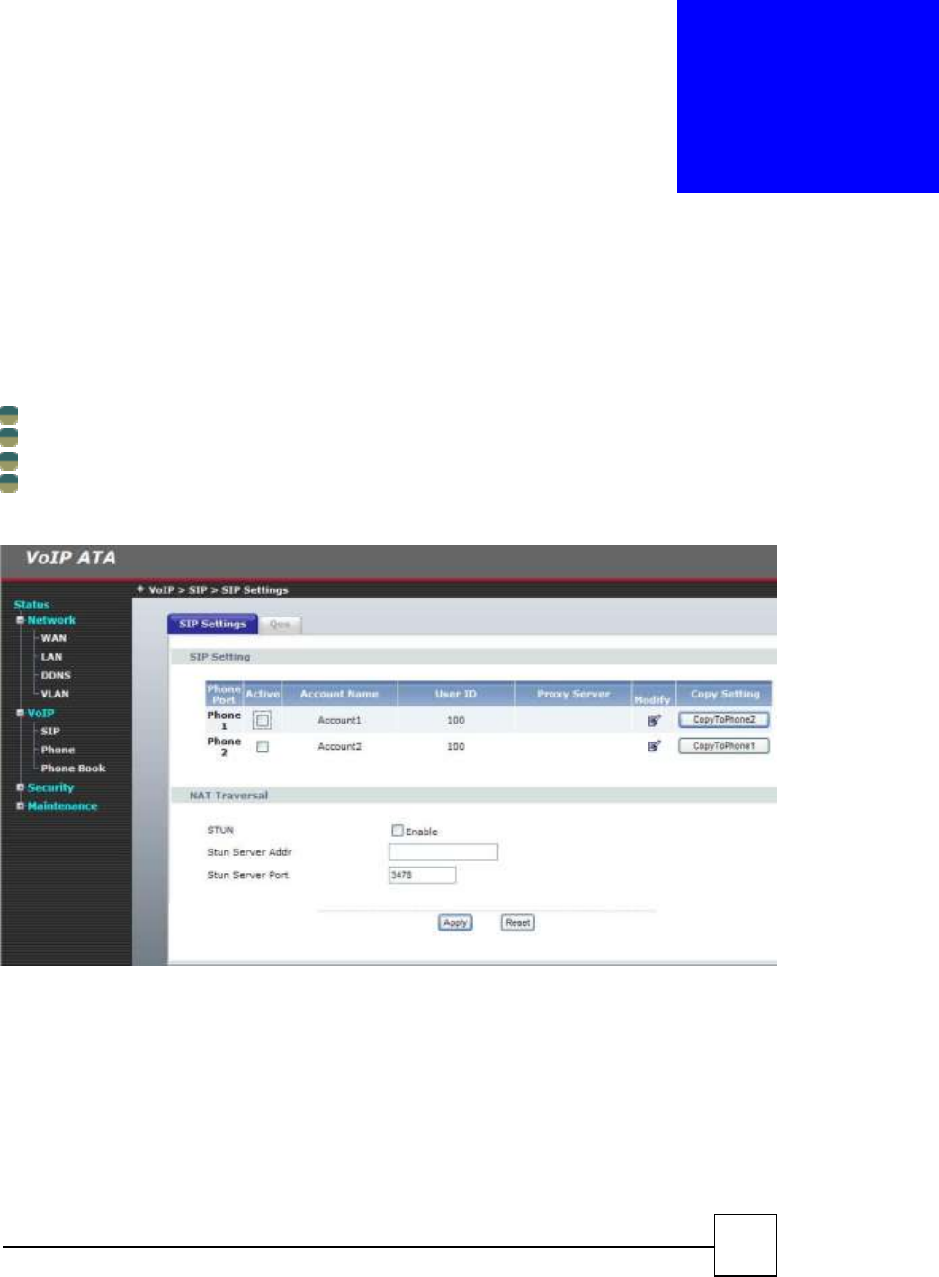
R7121-L1
31
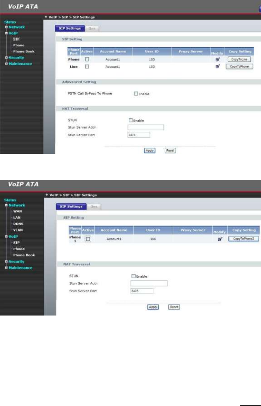
R7141-L1
R7111-L1
32
4.1 SIP Setting
Sip setting
In SIP Settings you can setup the Service Domain, Port Settings, Codec Settings, Codec ID Settings, RTP
Setting, RPort Setting and Other Settings. If the VoIP service is provided by ISP, you need to setup the
related information correctly then you can register to the SIP Proxy Server correctly.
In Service Domain Function you need to input the account and the related information in this page, please
refer to your ISP provider. You can register three SIP account in the VoIP Phone. You can dial the VoIP
phone to your friends via first enable SIP account and receive the phone from these three SIP accounts.
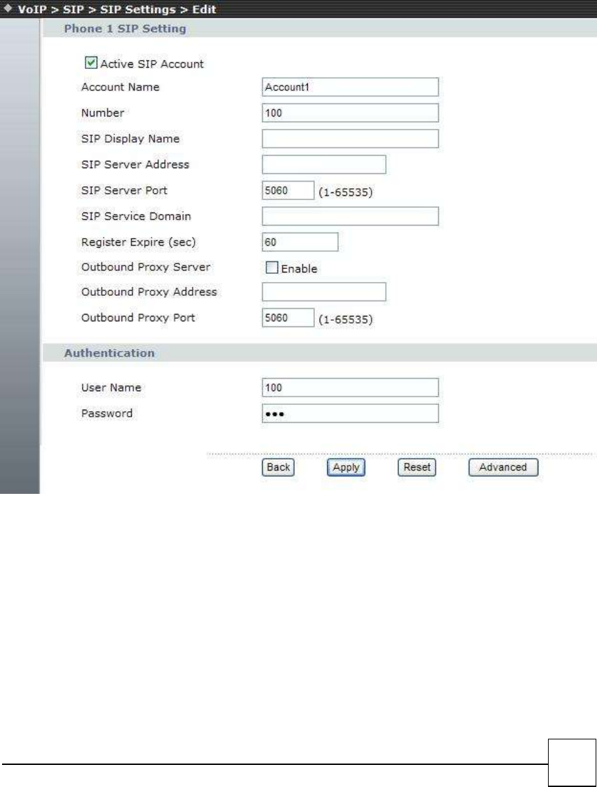
□Account Name: you can input the name you want to display.
□Number: you need to input the User Name get from your ISP.
□SIP Display Name: you can input the name you want to display.
□SIP Server Addr: Enable / Disable Register Proxy server and input the Proxy Addr get from your ISP.
□SIP Server Port: you need to input the Proxy Port get from your ISP.
□SIP Server Domain: you need to input the SIP Domain get from your ISP.
□Reg Expire (sec): SIP registration expired time.
□Outbound Proxy Server: you need to input the Outbound Proxy get from your ISP. If your ISP does not
provide the information, then you can skip this item.
□Outbound Proxy Address: Enable / Disable Register Outbound Proxy server and input the Outbound
Proxy Address get from your ISP.
33
You can see the Register Status in the Status item. If the item shows “Registered”, then your VoIP Phone is
registered to the ISP, you can make a phone call directly.
If you have more than one SIP account, you can following the steps to register to the other ISP.
When you finished the setting, please click the Apply button.
□User Name: you need to input the Register Name get from your ISP.
□Password: you need to input the Register Password get from your ISP.
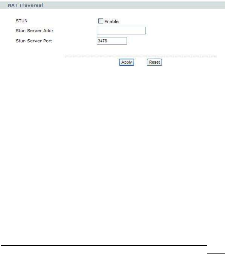
STUN Traversal
STUN {Simple Traversal of UDP through NATs (Network Address Translation)} is a protocol for
assisting devices behind a NAT firewall or router with their packet routing.
STUN enables a device to find out its public IP address and the type of NAT service its sitting
behind.
When you enable the STUN function, you must input the STUN server address.
34
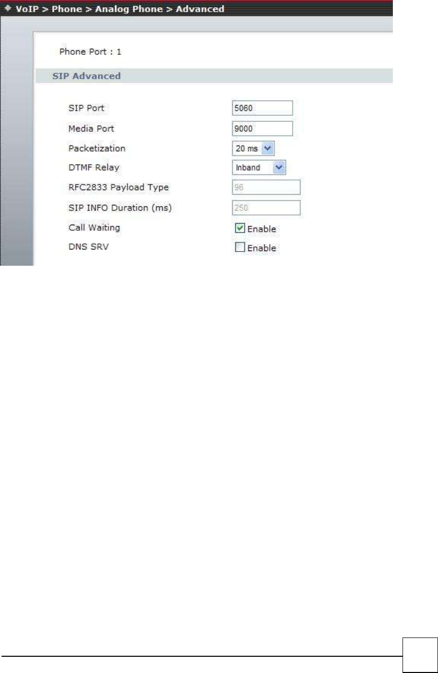
SIP Advance
□SIP Port Number - Assign the SIP port number of R7141-L1/R7121-L1/R7111-L1., default setting is 5060.
□Media Port Start - The starting range of port for RTP . Port number for initial of sending RTP packet.,
default setting is 9000.
□Packetization: Select the voice codec packetization interval in milliseconds. The default is 20 ms. This is
used to minimize loss that happens during transmission of voice data over the network.
□DTMF Setting - you can setup the RFC2833 Out-Band DTMF, Inband DTMF and Send DTMF SIP Info in this
page. To change this setting, please follow your ISP information. When you finished the setting, please
click the Submit button.
□RFC2833 Payload Type - Sending the DTMF tone as a RTP payload signal. The RFC2833 signaling
□SIP INFO Payload Type - Sending the DTMF tone as a RTP payload signal. The SIP INFO signaling
□PCM Type - Sending the DTMF tone as a RTP payload signal. The Inband DTMF signaling
□SIP INFO Duration (ms) - Modify SIPINFO duration time.
□Call Waiting - Call Waiting Setting function: If user doesn’t want to be inform there is a new incoming call,
user can set the function off.
□DNS Server: Select Enable to have the R7141-L1/R7121-L1/R7111-L1 Device query your ISP’s DNS server
for a list of any available SIP servers that it maintains. This is useful if your static SIP server exercise
difficulties, making it hard for you to make SIP calls.
35
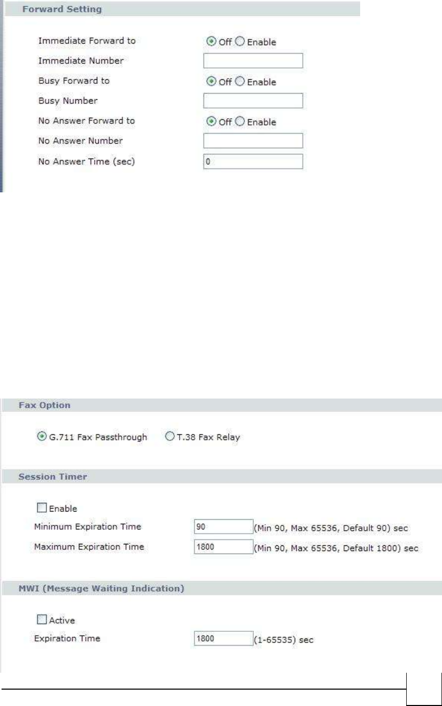
Forwarding Mode
You can setup the phone number you want to forward in this page. There are three type of Forward mode.
You can setup Immediate Forward, Busy Forward, and No Answer Forward by click the icon.
Immediate Forward: All incoming call will forward to the number you entered. You can input the phone
number. If you select this function, then all the incoming call will direct forward to the speed dial number
you entered.
Busy Forward: If you are on the phone, the new incoming call will forward to the number you entered.
No Answer Forward: If no one picks up the phone, the incoming call will forward to the number you
entered.
When you finished the setting, please click the Submit button.
36
FAX Option
G.711 Fax Pass through: Select this if the R7141-L1/R7121-L1/R7111-L1 should use G.711 to send fax messages. The
peer devices must also use G.711.
T.38 Fax Relay: Select this if the R7141-L1/R7121-L1/R7111-L1 should send fax messages as UDP packets through IP
networks. This provides better quality, but it may have inter-operability problems. The peer devices must also use
T.38
Session Timer
Enable: Select Enable if you want to define how long the R7141-L1/R7121-L1/R7111-L1 waits to receive a session-alive
packet for a voice session from the SIP server.
Minimum Expiration Time: Enter the minimum time the R7141-L1/R7121-L1/R7111-L1 waits for a session-alive packet
(90-65536 seconds). If a session-alive packet is not received during this time, the voice session is terminated.
Maximum Expiration Time: Enter the maximum time the R7141-L1/R7121-L1/R7111-L1 waits for a session-alive
packet (90-65536 seconds). If a session-alive packet is not received during this time, the voice session is terminated.
MWI (Message Waiting Indications)
Active: Select this if you want to hear a waiting (beeping) dial tone on your phone when you have at least one voice
message. Your SIP service provider must support this feature.
Expiration Time : Keep the default value, unless your SIP service provider tells you to change it. Enter the number of
seconds the SIP server should provide the message waiting service each time the R7141-L1/R7121-L1/R7111-L1
subscribes to the service. Before this time passes, the R7141-L1/R7121-L1/R7111-L1 automatically subscribes again.
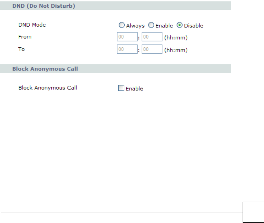
DND Setting
DND Setting: you can setup the DND setting to keep the device silence. You can choose Always or Enable
or Disable.
DND Always: All incoming call will be blocked until disable this feature.
DND Enable: Select Enable and the R7121-L1/R7141-L1/R7111-L1 will be blocked during the time period. If
the “From” time is large than the “To” time, the Block time will from 00:00 to 23:59
When you finished the setting, please click the Submit button.
If there is nothing need to change, please click the Save Change Item in the left side, then click the Save
button. The change you made will save into the system and the system will Reboot automatically.
Block Anonymous Call
Select to enable the option
37
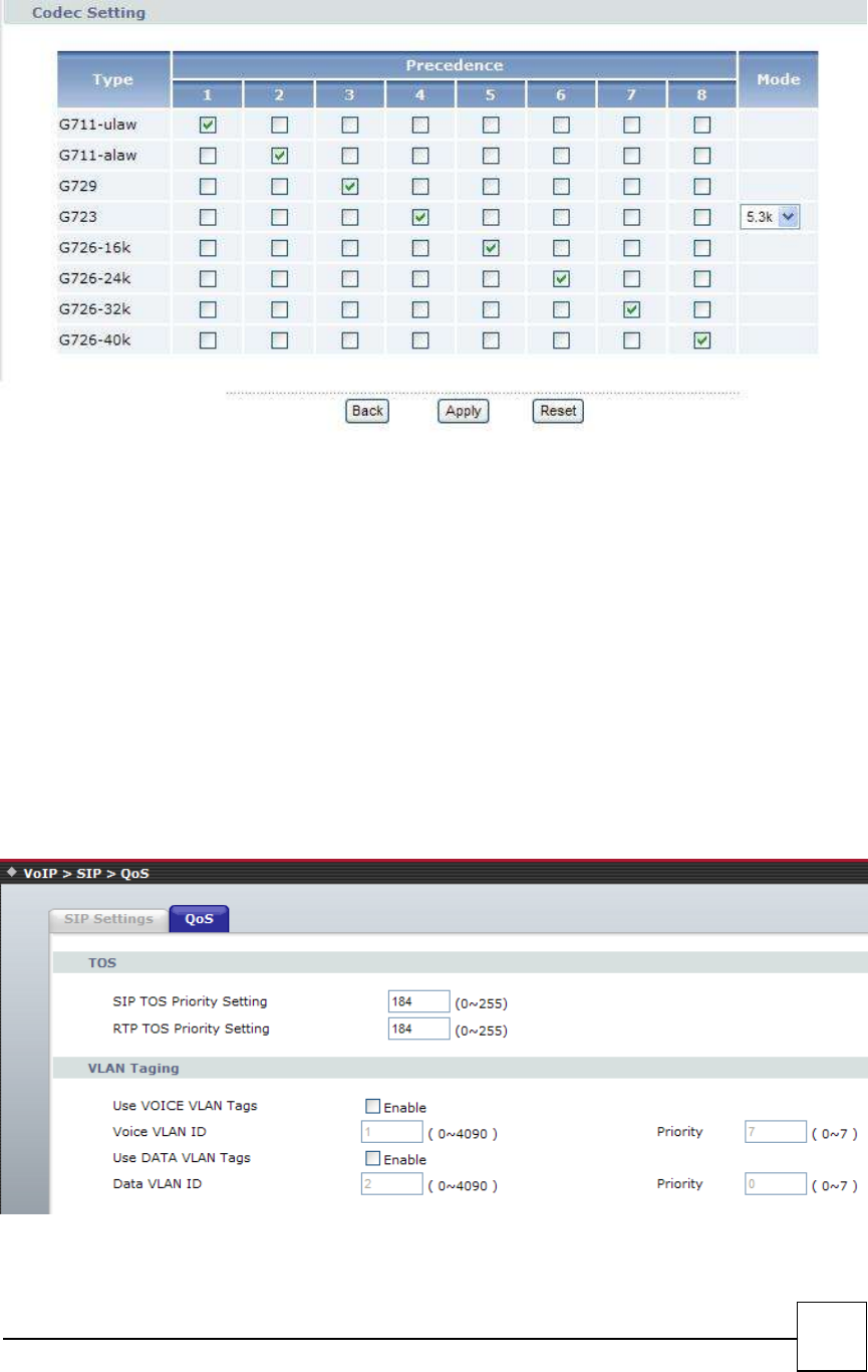
Codec
A CODEC is an algorithm for taking voice or video and compressing the information. This type of codec
combines analog-to-digital conversion and digital-to-analog conversion functions in a single chip. The
Codec is used to compress the voice signal into data packets. Each Codec has different bandwidth
requirement. There are 9 kinds of codec, G.711/Ulaw, G.711/Alaw, G.729, G.723(5.3k / 6.3k bps),
G.726(16K bps), G.726(24K bps), G.726(32K bps), G.726(40K bps)
QoS
The QOS (Quality Of Service) is to guarantee that the SIP and RTP should be transmitting at the same time
and Data couldn’t influence the Voice quality.
The QOS (Quality Of Service) is to guarantee that the Voice and Data should be transmitting at the same
time and Data couldn’t influence the Voice quality. When TOS bits is enabled, it will guarantee the Voice
have the first priority pass through the TOS enable devices.
VLAN Taging

38
VLAN Setting: You can set the VLAN setting in this page. There are two parts in this page. First one is to set
the packets related to the R7141-L1, and the second one is if you use the VLAN setting in the NAT Mode.
There are two kind of destination packets will come from the R7141-L1’s WAN port, one kind of packets
will go to the R7141-L1, the other will go through the LAN port to the PC.
VLAN Packets: if you enable the first VLAN Packets and set the VID, User Priority, then all the incoming
packets will be check with the IP Address and the VID.
Voice Vlan ID: You can follow your service provider to set your Voice Vlan ID.
Data Vlan ID: You can follow your service provider to set your Data Vlan ID.
User Priority: Defines user priority, giving eight (2^3) priority levels. IEEE 802.1P defines the operation for
these 3 user priority bits. Usually this will be defined by your service provider.
When you enable the first VLAN Packets and set the VID, User Priority, then all the incoming packets with
the TA’s IP address and the same VID will be accept by the TA. If the incoming packets with the TA’s IP
address but the different VID then the packets will be discard by the R7141-L1. The Other incoming
packets with different IP address will go through the LAN port to the PC.
39
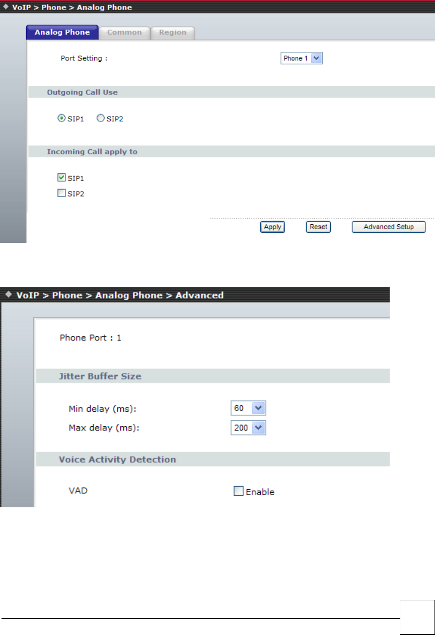
4.2 Phone
Analog Phone
Select Phone 1 or Phone 2 first, then, click the Advance Setup button.
Advanced Setup:
Jitter Buffer Control
In R7141-L1/R7121-L1 VoIP device, The jitter buffer control is a shared data area where voice packets
can be stored , collected , and sent to the voice shared Buffer in evenly spaced intervals. modify in packets
arrival time, called jitter, can occur because of network congestion, timing drift, or route changes.
□Min delay (ms): Select min delay buffer time.( 40ms – 100 ms)
40
□Max delay (ms): Select Max delay Buffer time.( 130ms – 300ms)
□Optimization factor: Controls quickly the length of the Jitter Buffer is increased when Voice RTP on the
network. .Default is 7
□Voice Active Detector - It is used in speech encoding software to determine if the voice being encoded is
human speech or background noise
Voice Activity Detection
If this function is enabled, when silence is occurred for a period of time, no data will be sent across the
network during this period in order to save bandwidth.
(If you use Asterisk, please disable Silence Compression, it maybe make you call disconnect.)
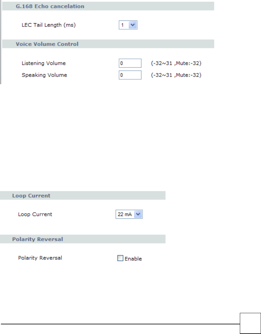
G.168 Echo cancelation
Select the tail lengths of 1ms, 2ms, 4ms, 8ms, 16ms, 32ms
Voice Volume control
□(Phone In)Speaker Voice Gain (db)- Sets a specific sound intensity for receiving sound. Select a level from
-32 to 31,
□(Phone out)MIC Voice Gain (db)- Sets a specific sound intensity for transmitting sound. Select a level
from -32 to 31,
Loop Current
Select the loop current
Polarity Reversal
41
As Callee Answer - Check this box to generate line polarity reversal while the remote user picks up the
phone call. As Callee On-Hook - Check this box to generate line polarity reversal while the remote user
hangs off the phone call.
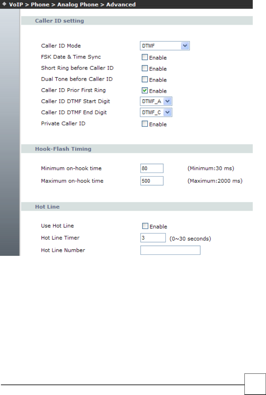
Caller ID Mode:
FSK Date & Time Sync: Send FSK Date & Time to display device.
Reverse Polarity before Caller ID: Send Reverse Polarity before Caller ID
Short Ring before Caller ID: Send short ring before caller ID.
Dual Tone before Caller ID: Send Dual Tone before Caller ID.
Caller ID prior First Ring: Send Caller ID before first ring.
Caller ID DTMF Start Digit: Set Caller ID DTMF start digit.
Caller ID DTMF END Digit: Set Caller ID DTMF start digit.
42
Hook-Flash Timing
Minimum on-hook time default =30 ms
Maximum on-hook time default =2000 ms
Hot Line
This service allows you to make a call to a pre-programmed number by only lifting the handset.
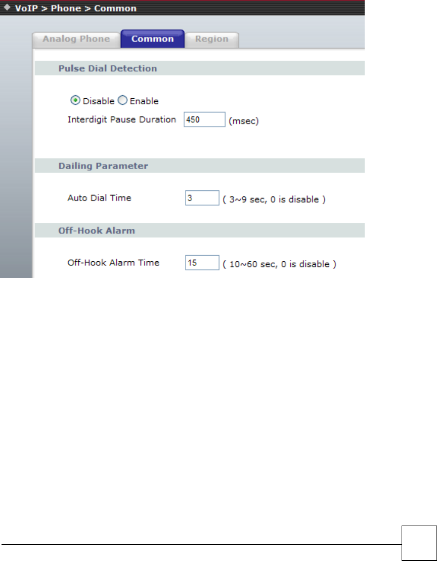
Common
Dialing Parameter
□Auto Dial Time- If no other number is being dialed within this interval, the R7141-L1 will terminate this
call. Assign the time interval from 1 to 9 seconds.
Off-Hook Alarm
□Off-Hook Alarm Time - Set has been off-hook, after this time, user will hear alarm. .
43
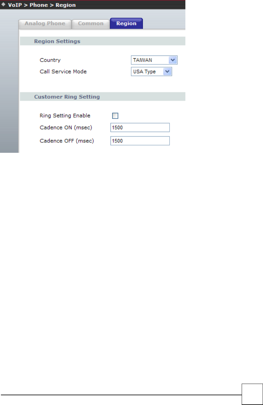
Region
Region Setting - Adjust the tone frequency according to each country. Select a country from the pull-down
menu.
44
4.3 Phone Book
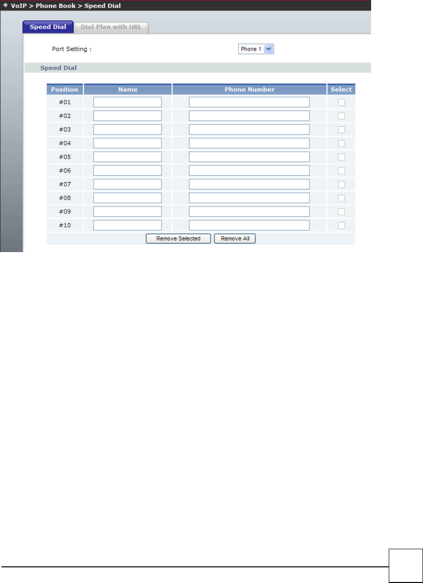
Speed Dial
Speed Dial lets you define a button or a set of buttons to link to a specific number defined in Speed Dial
list.
□Position - Select the speed dial shortcut to use from 0 to 9.
□Name–Phone number note.
□Phone Number - Enter the international number to dial.
45
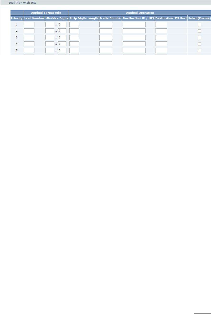
Dial Plan With URL
The “Dialing plan with URL” need to set when the user use the method of Peer-to-Peer SIP VoIP call or SIP
Proxy Server Mode. The SIP Dialing Plan has two kinds of directions: Outgoing (call out).
□“Lead Number” is the leading digits of the call out dialing number.
□“Min-Max Digits” has two text fields need filled: “Min Length” and “Max Length” are the
min/max allowed length you can dial.
□“Strip Digits Length” is the number of digits that will be stripped from beginning of the dialed
number.
□“Prefix Number” is the digits that will be added to the beginning of the dialed number.
□“Destination IP/ URI” is the IP address / Domain Name of the destination
R7121-L1/R7141-L1/R7111-L1 that owns this phone number.
□“Destination SIP Port” is port of the destination R7121-L1/R7141-L1/R7111-L1 use.(Default is
5060)
□Call By PSTN: Priority to dial from PSTN
46
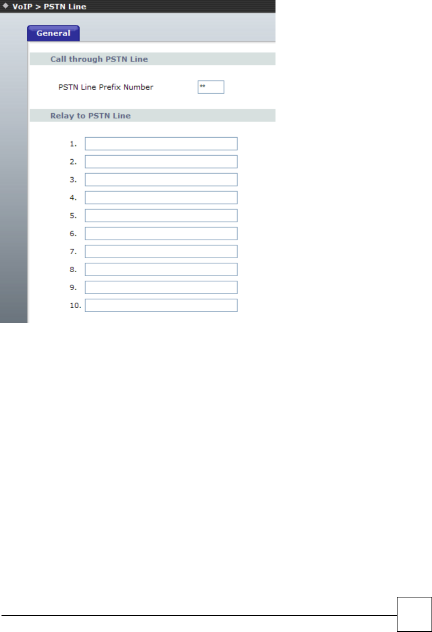
4.4 PSTN Line (R7141-L1 only)
Call out by PSTN line
□call through PSTN line: set up the prefix digit function key.
For example, the PSTN line Prefix Number is **. It means that the analog phone connect to FXS port can
press **, then, get a dial tone of PSTN port to dial destination number via PSTN port.
□Relay to PSTN Line: There are 10 lists you can set the Relay to PSTN line item.
For example, when we setup the item as 999, it means when the analog phone connects to FXS port dial
999, the RG110 will call 999 via PSTN port, (you don’t need to press “PSTN Line Prefix number” before dial
999)
47
5
Security
5.1 Firewall
IP Filtering
Mac Filtering
Port Filtering
Content Filtering
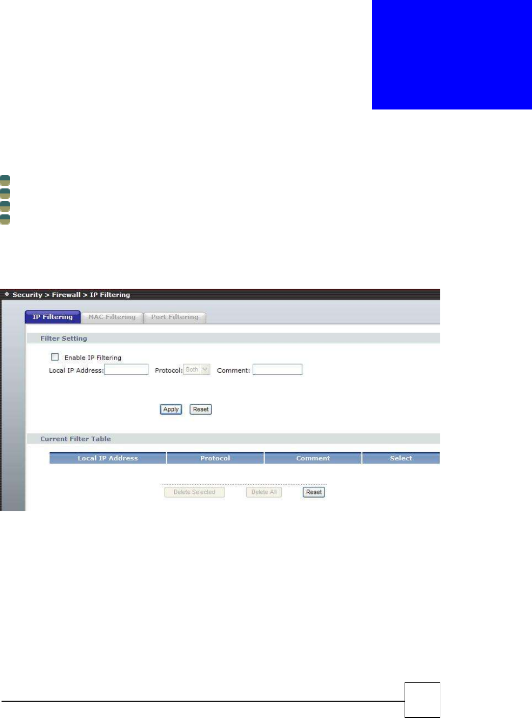
IP Filtering
Entries in this table are used to restrict certain types of data packets from your local network to Internet
through the Gateway. Use of such filters can be helpful in securing or restricting your local network.
□ Enable/Disable IP Filtering - The IP address filter function ,control a network IP address from your local
network to Internet through the Gateway ,default setting is disable.
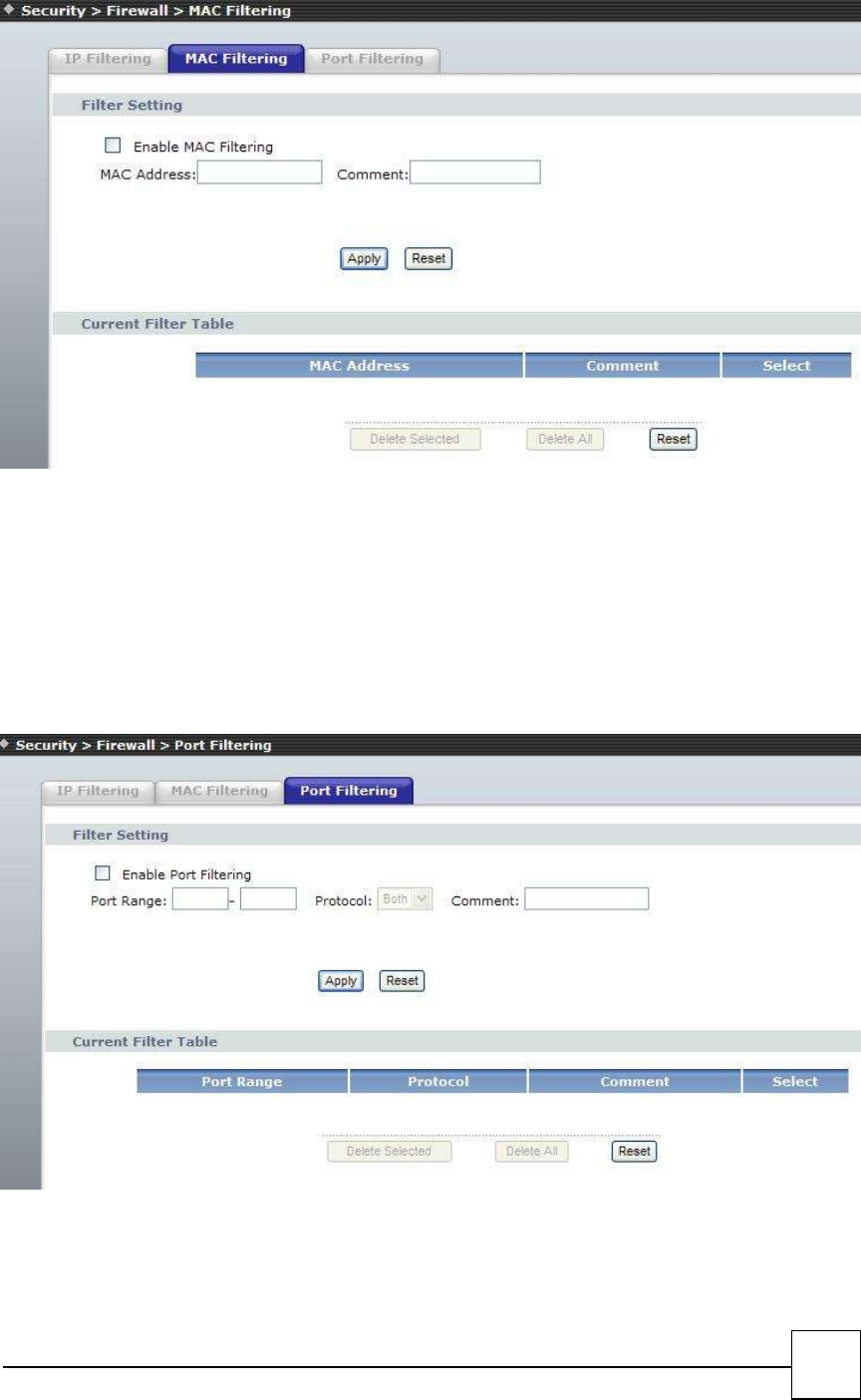
Mac Filtering
Entries in this table are used to restrict certain types of data packets from your local network to Internet
through the Gateway. Use of such filters can be helpful in securing or restricting your local network.
48
□MAC Enable/Disable –from your local network to Internet through the Gateway MAC filter
function,default setting is disable.
Port Filtering
Entries in this table are used to restrict certain types of data packets from your local network to Internet
through the Gateway. Use of such filters can be helpful in securing or restricting your local network
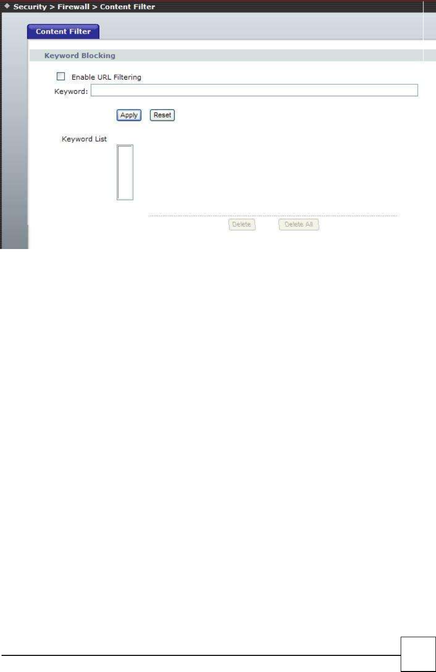
Content Filtering
URL filter is used to deny LAN users from accessing the internet. Block those URLs which contain
keywords listed below.
49
URL filter allows you to block sites based on a black list and white list. Sites matching the black list but
not matching the white list will be automatically blocked and closed.
□Enable - Enable/Disable the URL filter function, default setting is Disable.
□Client IP - This is the Clinet IP is LAN address.
□URL Filter String - This is the filter URL.
Example: “http://www.yahoo.com/”

50
6
Maintenance
System
Account setting
Time Zone
Auto Provision
DDNS
Tool
Configuration
Upgrade Firmware
Ping Test
Restart
Log
System Log
51
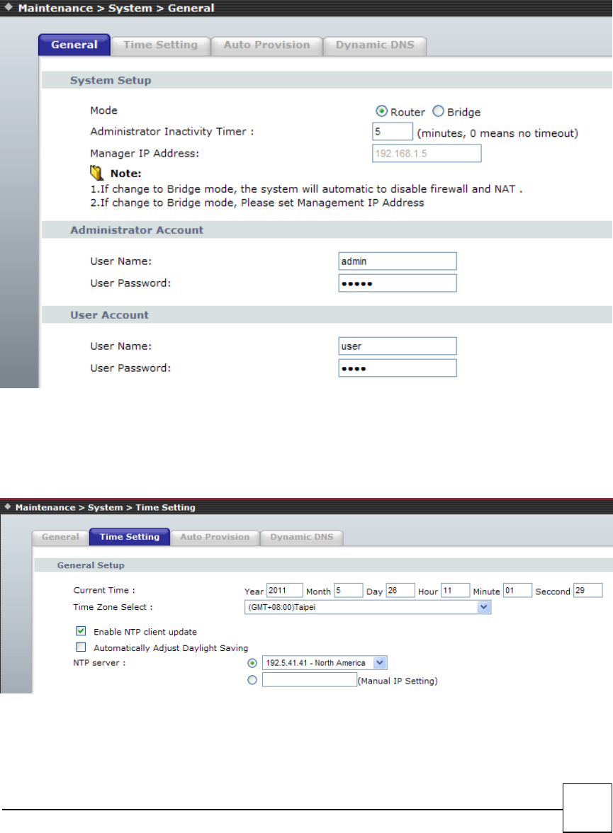
6.1 System
General
This page is used to set the Router or Bridge mode. And the account to access the web server of Access
Point. Empty user name and password will disable the protection.
Note: If select Bridge mode, the system will disable the firewall and NAT automatically.
If select Bridge mode, please set the Management IP Address
Time Setting
You can maintain the system time by synchronizing with a public time server over the Internet.
Auto Provision
Enable or disable the auto-provisioning feature. If enabled, the phone will try to download
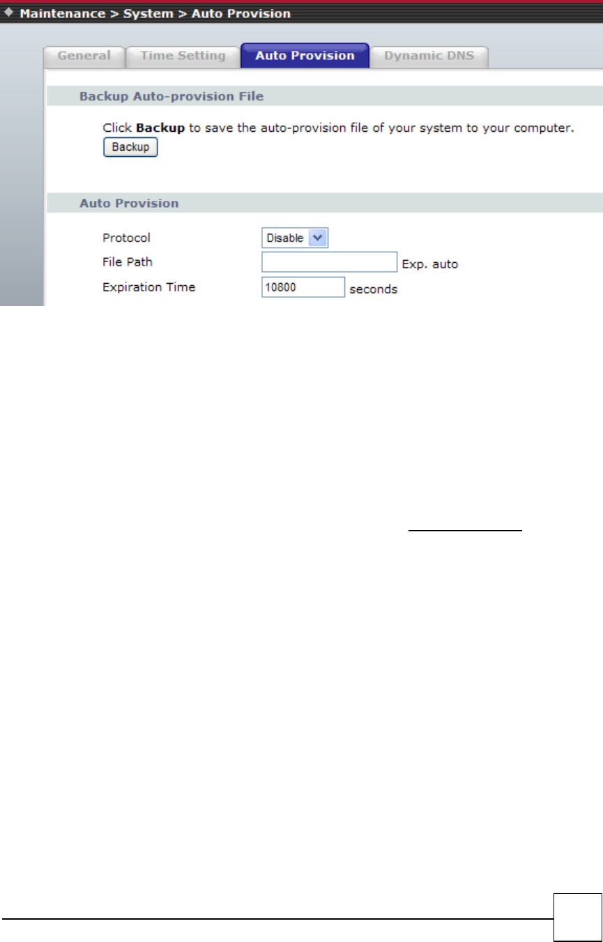
52
the two configuration files from the provisioning server via FTP/TFTP / HTTP on system startup;
Default is disabled.
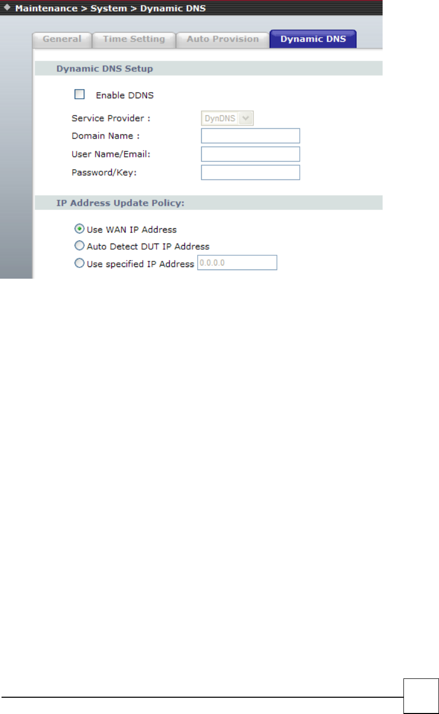
DDNS
Dynamic DNS is a service, that provides you with a valid, unchanging, internet domain name (an URL) to
go with that (possibly ever changing) IP-address.
The DDNS (Dynamic DNS) service allows you to alias a dynamic IP address to a static hostname,
allowing your computer to be more easily accessed from various locations on the Internet.
Without DDNS, the users should use the WAN IP to reach internal server. It is inconvenient for the users
if this IP is dynamic. With DDNS supported, you apply a DNS name (e.g., www.R7121-L1.com) for your
server (e.g., Web server) from a DDNS server. The outside users can always access the web server using
the www.ata.com regardless of the WAN IP.
When you want your internal server to be accessed by using DNS name rather than using the dynamic
IP address, you can use the DDNS service. The DDNS server allows to alias a dynamic IP address to a static
hostname.
Unlike DNS that only works with static IP addresses, DDNS works with dynamic IP addresses, such as
those assigned by an ISP or other DHCP server. DDNS is popular with home networkers, who typically
receive dynamic, frequently-changing IP addresses from their service provider.
DDNS is a method of keeping a domain name linked to a changing (dynamic) IP address. With most
Cable and DSL connections, you are assigned a dynamic IP address and that address is used only for the
duration of that specific connection. With the R7121-L1, you can setup your DDNS service and the ATA
will automatically update your DDNS server every time it receives a different IP address.
53
□Enable - Enable/Disable the DDNS service, default setting is Disable.
□DDNS Server Type - The R7141-L1 support two types of DDNS, DynDns.org or TZO.net
□Domain Name - The hostname which you register in DynDns.org or TZO.net website.
□DDNS Username - The username which you register in DynDns.org or TZO.net website.
□DDNS Password - The password which you register in DynDns.org or TZO.net website.
54
6.2 Tools
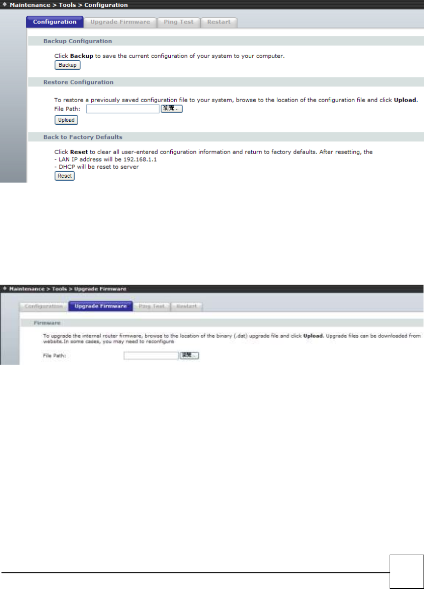
Configuration
This page allows you save current settings to a file or reload the settings from the file which was saved
previously. Besides, you could reset the current configuration to factory default.
Upgrade Firmware
This page allows you upgrade the Access Point firmware to new version. Please note, do not power off the
device during the upload because it may crash the system.
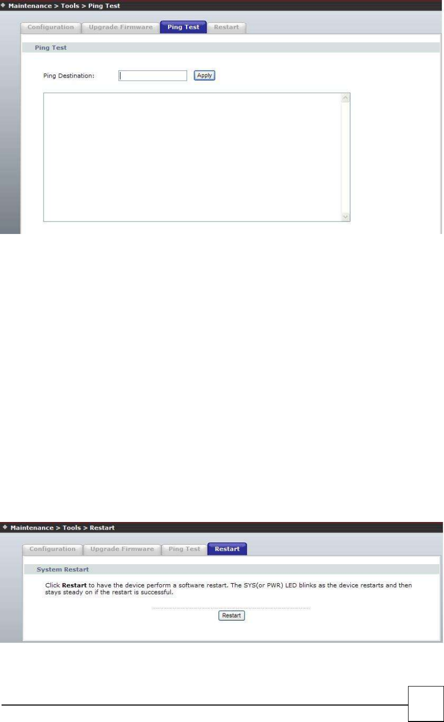
Ping Test
Ping function you can Ping IP or Domain.
55
EX:
Ping 168.95.1.1 and response as follow:
PING 168.95.1.1 (168.95.1.1): 56 data bytes
64 bytes from 168.95.1.1: icmp_seq=0 ttl=247 time=80.0 ms
64 bytes from 168.95.1.1: icmp_seq=1 ttl=247 time=100.0 ms
64 bytes from 168.95.1.1: icmp_seq=2 ttl=247 time=240.0 ms
64 bytes from 168.95.1.1: icmp_seq=3 ttl=247 time=30.0 ms
--- 168.95.1.1 ping statistics ---
5 packets transmitted, 4 packets received, 20% packet loss
round-trip min/avg/max = 30.0/112.5/240.0 ms
Restart
Restart function you can restart theR7121-L1/R7141-L1/R7111-L1 device. If you want to restart the
R7121-L1/R7141-L1, you can just click the Reboot button, than the VoIP Phone will automatically.
If for any reason the device is not responding correctly, you may want to restart the
R7121-L1/R7141-L1/R7111-L1 system
56
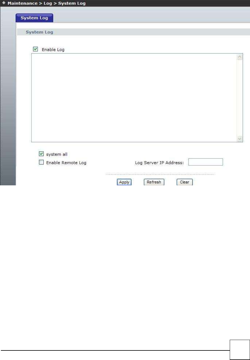
6.3 Log
If you want to Log the R7141-L1/R7121-L1/R7111-L1 system log , you can enable log and enable system
all ,
The system will record system log .
57
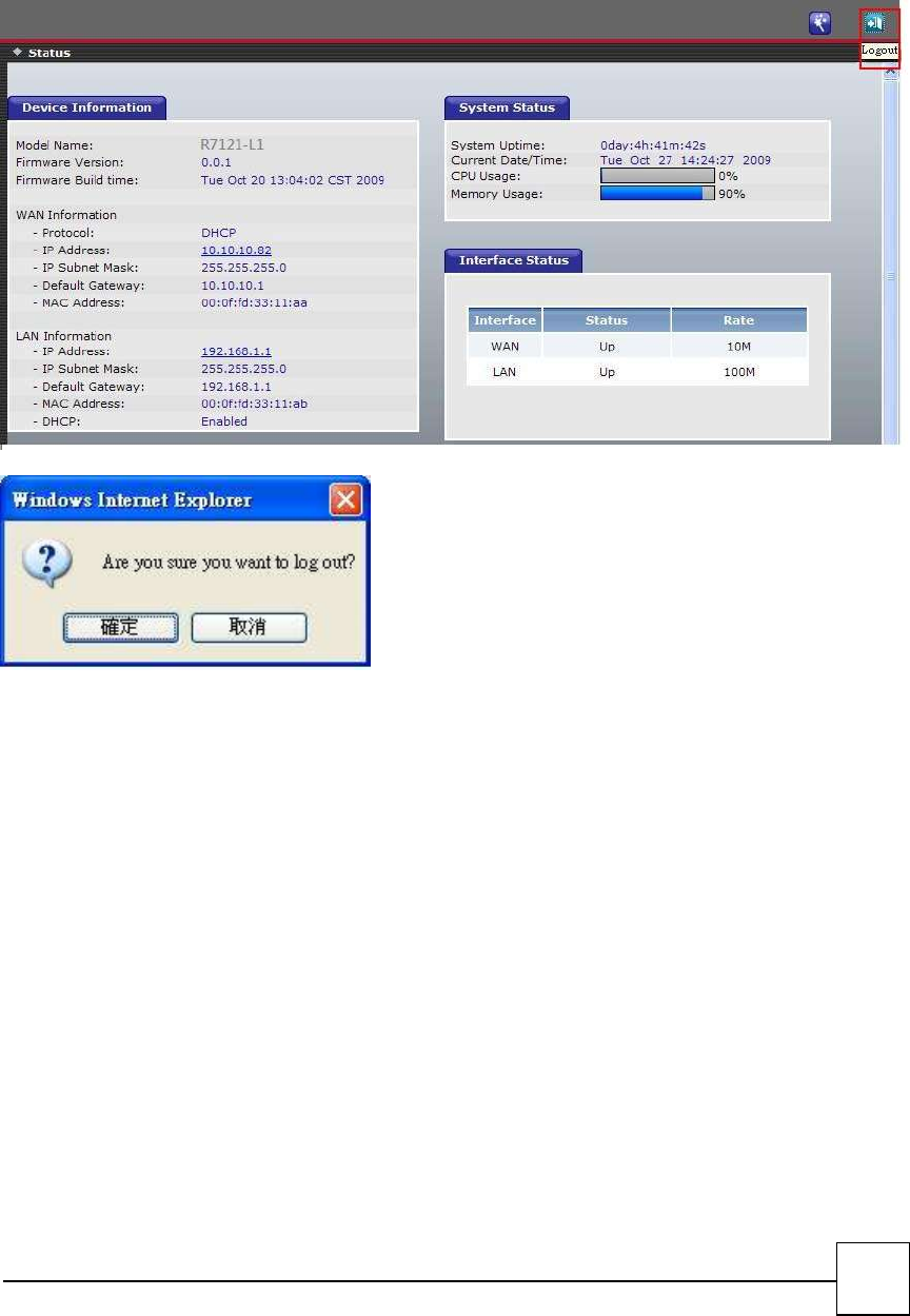
Logout
If you need to logout administrator right for web-access, please click the Logout link. The web system
management interface will auto-logout with 1800 sec default value.
58
Information
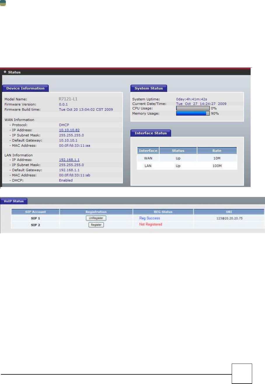
System Information
System Status
This page shows the current status and some basic settings of the device.
Click System Information to display system status, The Device Information has WAN type, and LAN type,
Phone Status, more Status…etc.
This page displays the current information for the device. It will display the LAN、 WAN and system
firmware information. This page will display different information for you, according your WAN setting
(Static IP, DHCP, PPPoE, PPTP).
If your WAN connection is set up for Dynamic IP address, there will be a Release button and Renew
button. Use Release to disconnect from your ISP and use Renew to connect to your ISP.
If your WAN connection is set up for PPPoE, there will be a Connect button and Disconnect button. Use
"Disconnect" to drop the PPPoE connection and use "Connect" to establish the PPPoE connection

59
IVR Command
Can use the fxs port keypad to operator R7121-L1/R7141-L1/R7111-L1, follow the
instruction to listen R7121-L1/R7141-L1 configuration.
Category
Command
Definition
Voice Network Settings
#120
Voice IP address
#121
Voice IP type
#123
Voice netmask
#124
Voice gateway
#125
Voice DNS
#128
Voice firmware Version
Appendix
A - FAQ List
1. What is the default administrator password to login to the R7121-L1/R7141-L1/R7111-L1? How to
Login?
A: By default, default username is “admin”, default password is also “admin” to login to the router. For
security, you should modify the password to protect your gateway against hacker attacks.
Default Wan Port Access type is DHCP Client, LAN Port IP Address is “192.168.1.1”.Loging Web User
Interface, open the Bowser (IE/FireFox) and input IP address.
2. I forgot the administrator password. What should I do?
A: Press the Reset button on the rear panel for over 5 seconds to reset all settings to default factory
values. Then you can use the default Username/Password to Login Web UI.
3. Why is it that I can ping to outside hosts, but not access Internet Web sites?
A: Check the DNS server settings on your PC. You should get the DNS servers settings from your ISP. If
your PC is running a DHCP client, remove any DNS IP address setting. As the router will assign the DNS
settings to the DHCP-client-enabled PC.
4. What is the maximum number of IP addresses that the DHCP server of the gateway can assign to
local PCs?
A: The built-in DHCP server can support 253 IP addresses for local network usage.
5. Why can I call out by R7121-L1/R7141-L1/R7111-L1?
A: Please check your R7121-L1/R7141-L1/R7111-L1 is registered SIP Proxy Server (ITSP), and chink your
Internet works fine. R7121-L1/R7141-L1/R7111-L1 can’t make a call without Internet or SIP Account that
from ITSP supply. You must have a SIP account or know the other ATA/Gateway IP/Domain Name, than
you can make a VoIP call.
6. I can’t use web Interface to setting R7121-L1/R7141-L1/R7111-L1, How can I do?
60
A: Please check your PC connects the R7121-L1/R7141-L1/R7111-L1 Lan port or PC and
R7121-L1/R7141-L1/R7111-L1 with the same Subnet. If you PC aren’t at the same Subnet, you can’t Login
the R7141-L1 Web interface. Else you let your R7121-L1/R7141-L1/R7111-L1 on Public Internet (Public IP
address).
7. Why does the one way talk happen?
A: Generally, one way talk happen when use the different codec between VoIP devices make call. Please
check and setting the same codec, most one way talk will be solved.
8. Why can I call out when the R7121-L1/R7141-L1/R7111-L1 under the NAT?
A: Most VoIP products have problem in NAT Pass through. By SIP, there are many NAT Pass through
Function can solve 80% NAT Problem. You can choose STUN/Outbound Proxy/ Symmetric RTP to Pass
through NAT, you don’t set any other setting (DMZ/Virtual Server) by router side. If you use
STUN/Outbound Proxy, you must have a STUN/Outbound Proxy Server to support. If they can’t pass NAT,
please open the DMZ/Virtual Server by Router/NAT/Firewall.
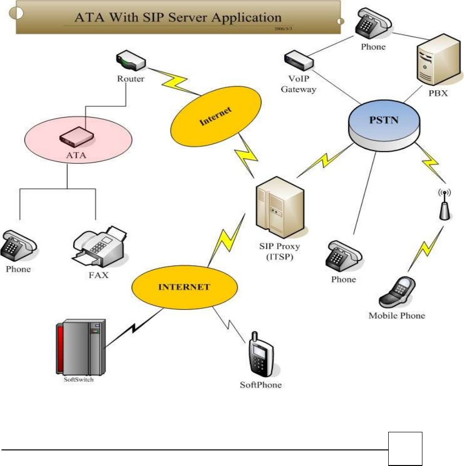
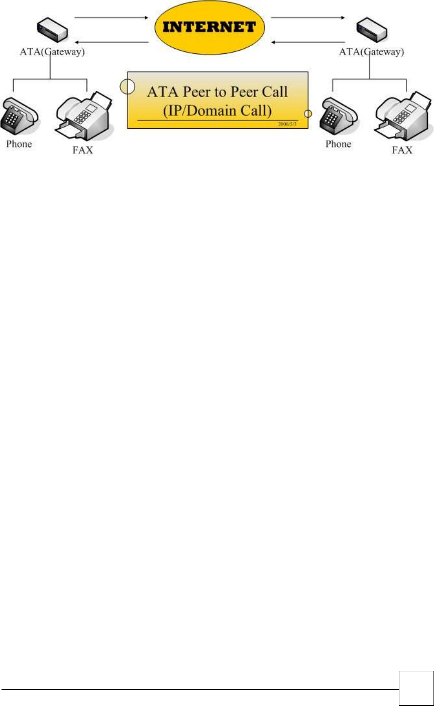
B - Scenario Application Samples
61
FCC ID: 2AB3KR7121-L1
NOTE: This equipment has been tested and found to comply with the limits for a
Class B digital device, pursuant to part 15 of the FCC Rules. These limits are
designed to provide reasonable protection against harmful interference in a
residential installation. This equipment generates uses and can radiate radio
frequency energy and, if not installed and used in accordance with the instructions,
may cause harmful interference to radio communications. However, there is no
guarantee that interference will not occur in a particular installation. If this
equipment does cause harmful interference to radio or television reception, which
can be determined by turning the equipment off and on, the user is encouraged to
try to correct the interference by one or more of the following measures:
- Reorient or relocate the receiving antenna.
- Increase the separation between the equipment and receiver.
-Connect the equipment into an outlet on a circuit different from that to which the
receiver is connected.
-Consult the dealer or an experienced radio/TV technician for help
Changes or modifications not expressly approved by the party responsible for compliance
could void the user's authority to operate the equipment. This device complies with Part
15 of the FCC Rules. Operation is subject to the following two conditions:
(1) this device may not cause harmful interference, and
(2) this device must accept any interference received, including interference that may
cause undesired operation.