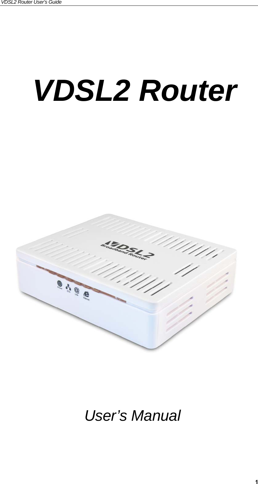
Eltek Technologies V7100 1 Port VDSL2 Router User Manual Manual V7100 Ax
Eltek Technologies Ltd 1 Port VDSL2 Router Manual V7100 Ax
UserManual.wiki
>
Eltek Technologies
>
V7100 User Manual
User Manual
Navigation menu
Upload a User Manual
Namespaces
Wiki Guide
HTML
PDF
Info
Views
User Manual
Discussion / Help
Navigation
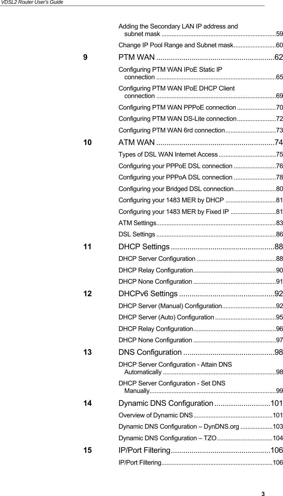
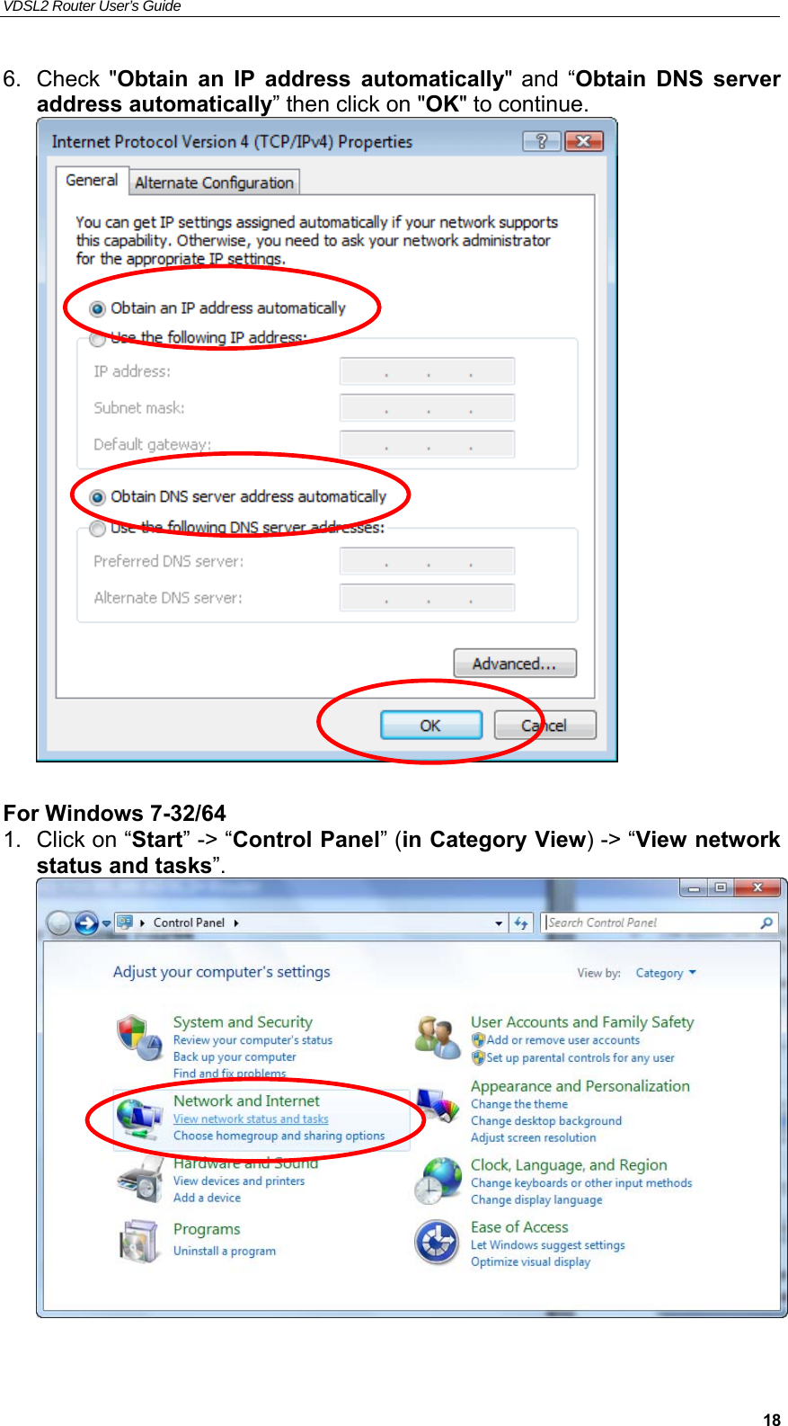
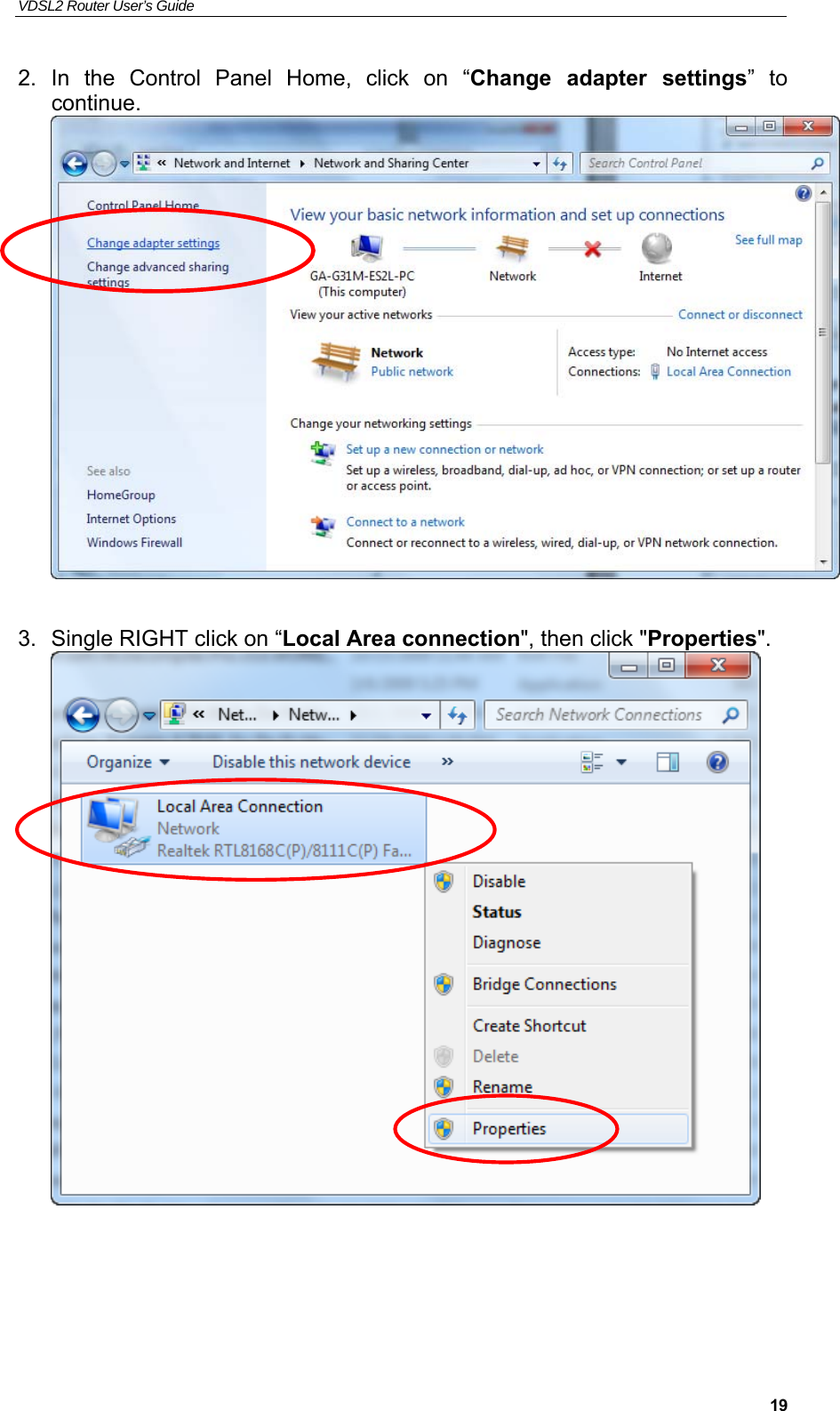
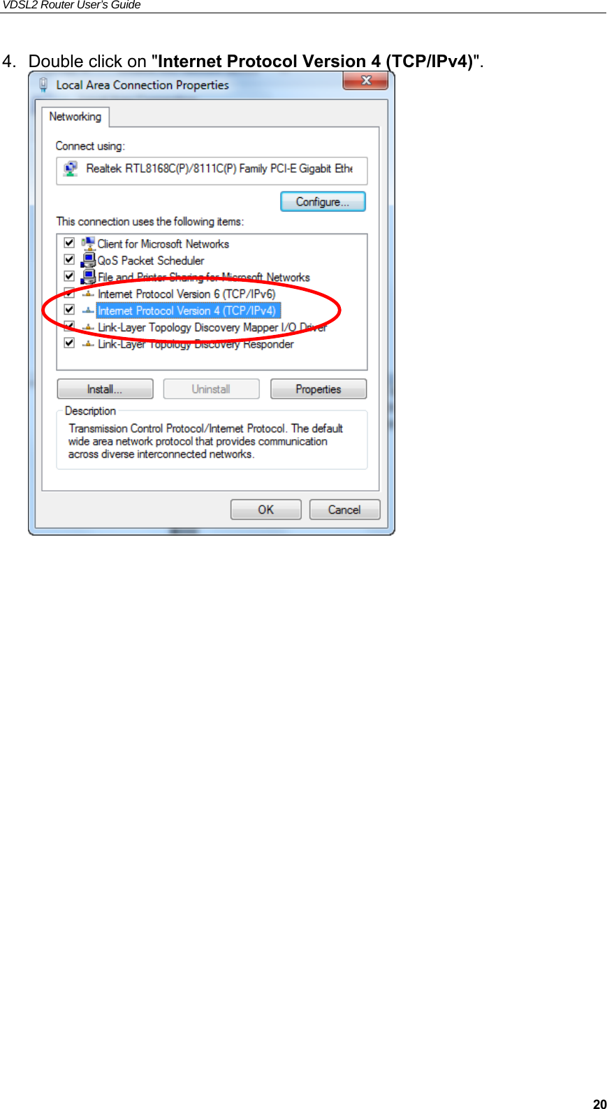
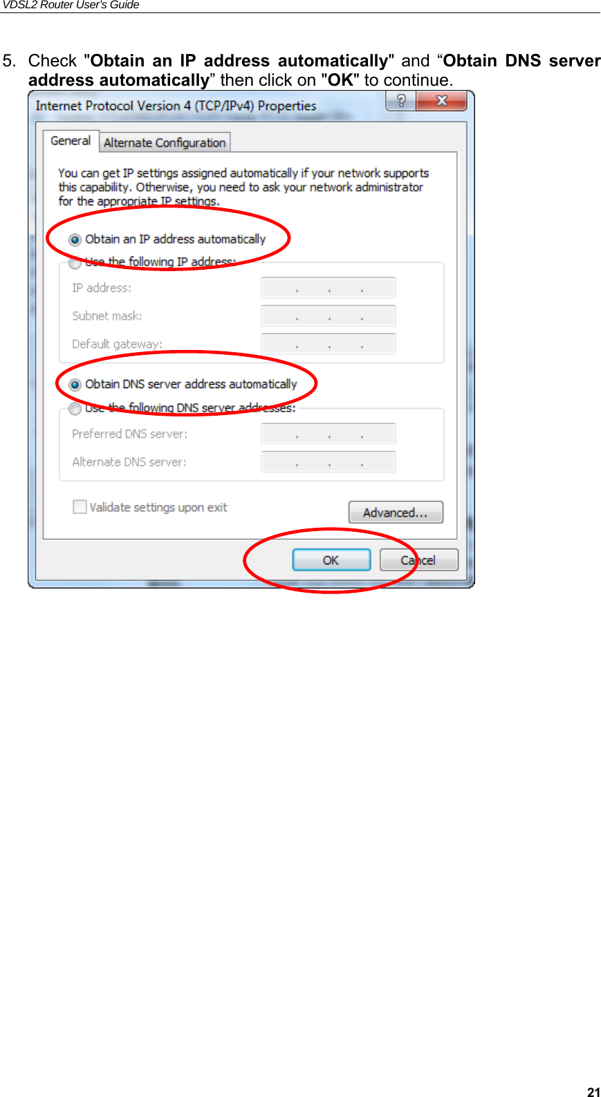
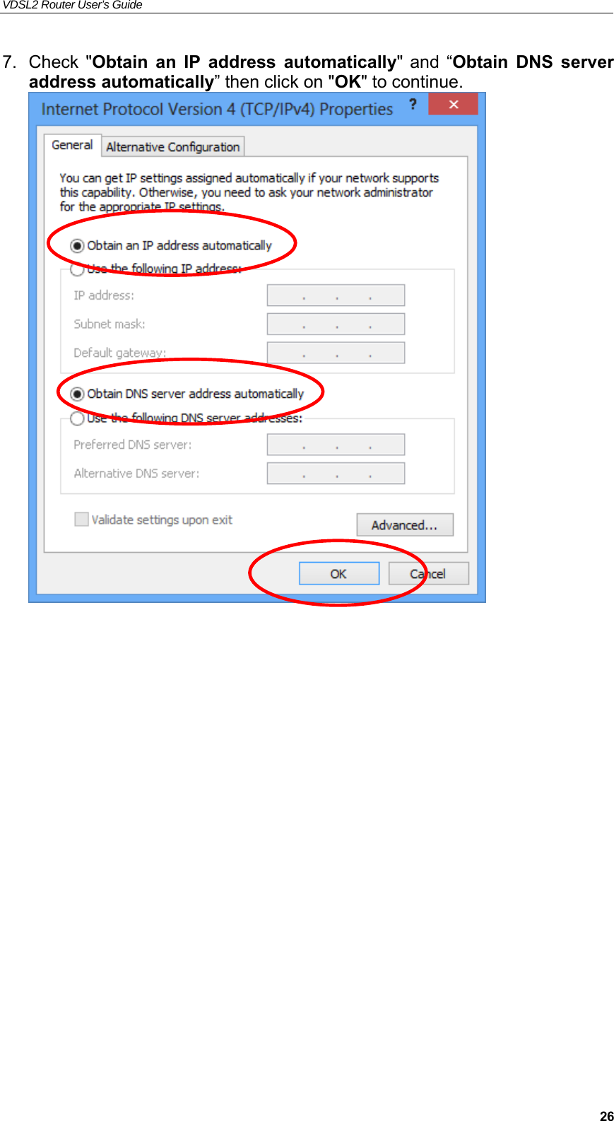


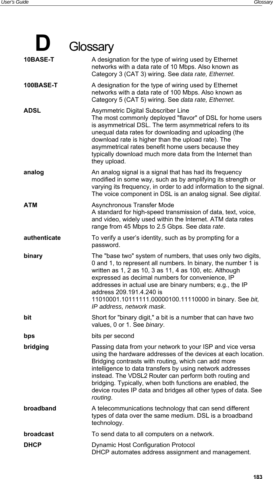
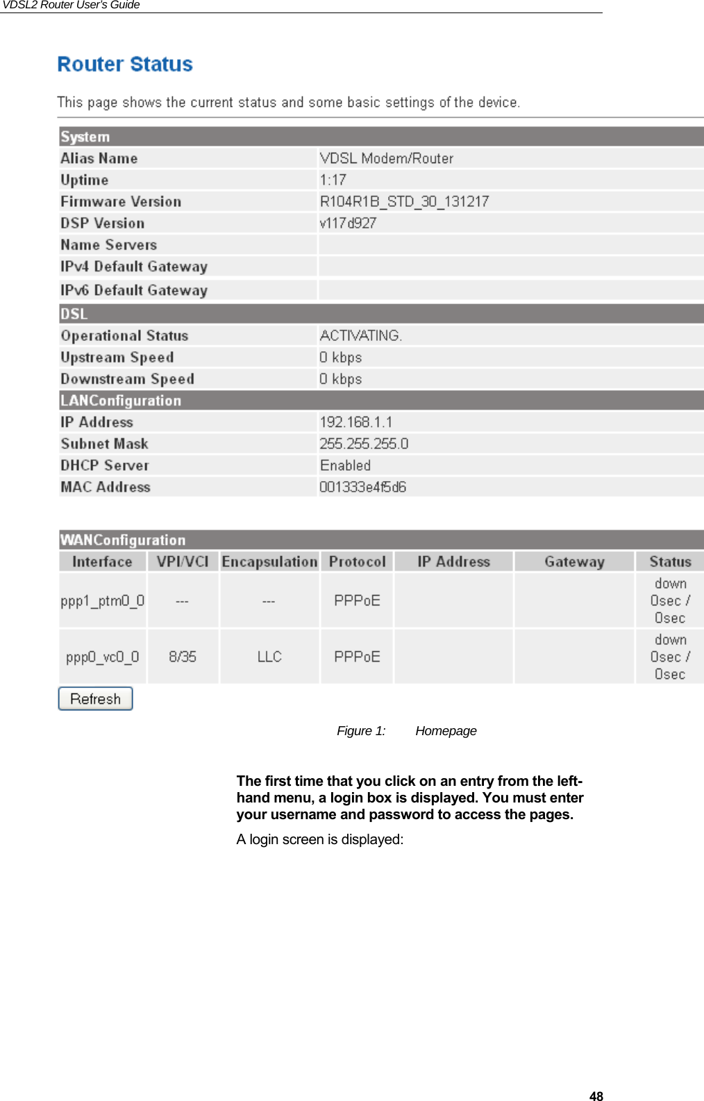
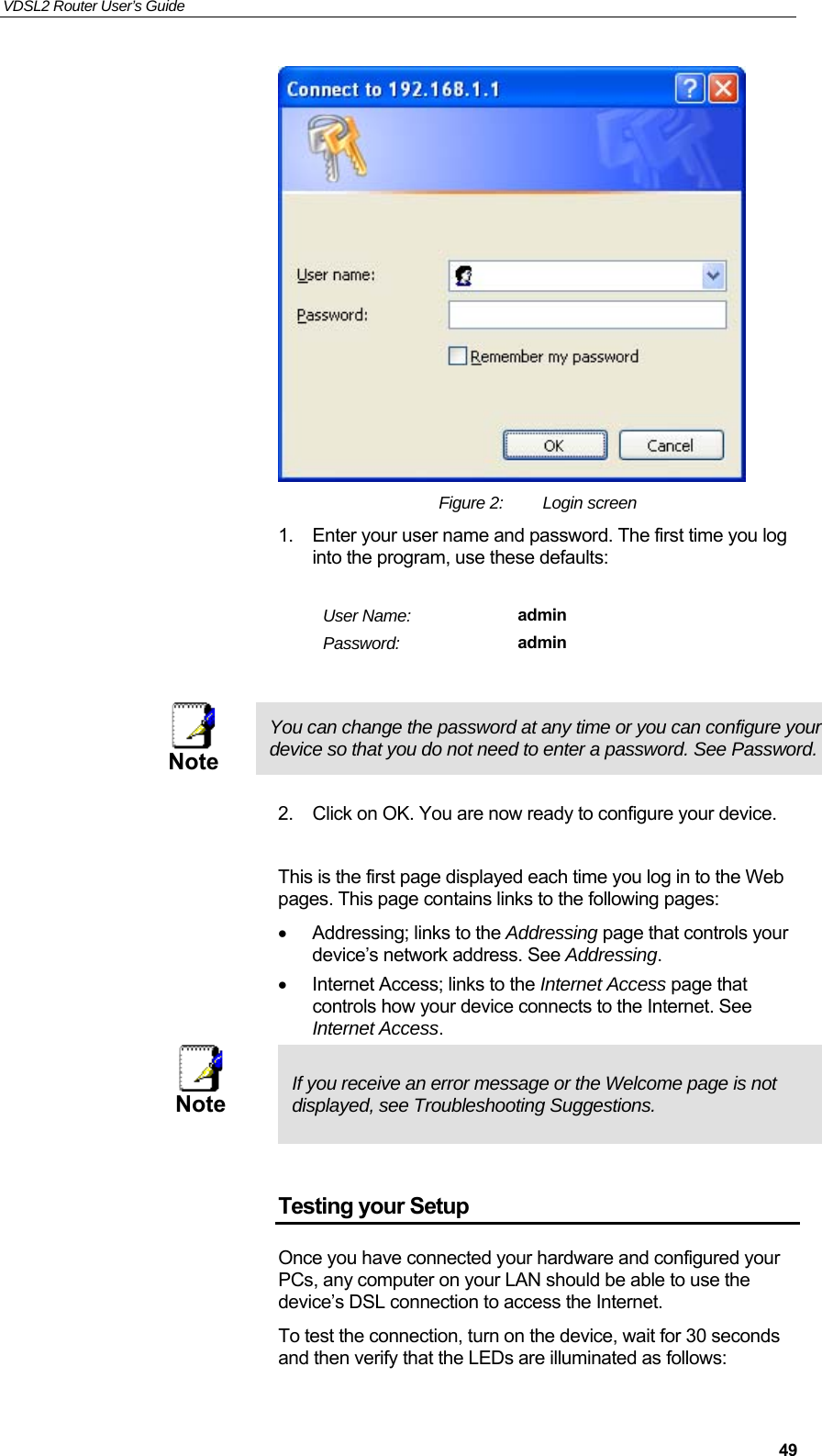
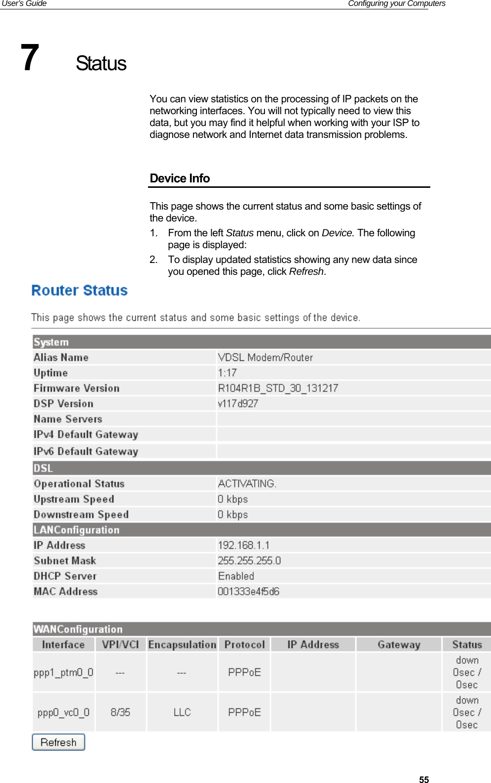
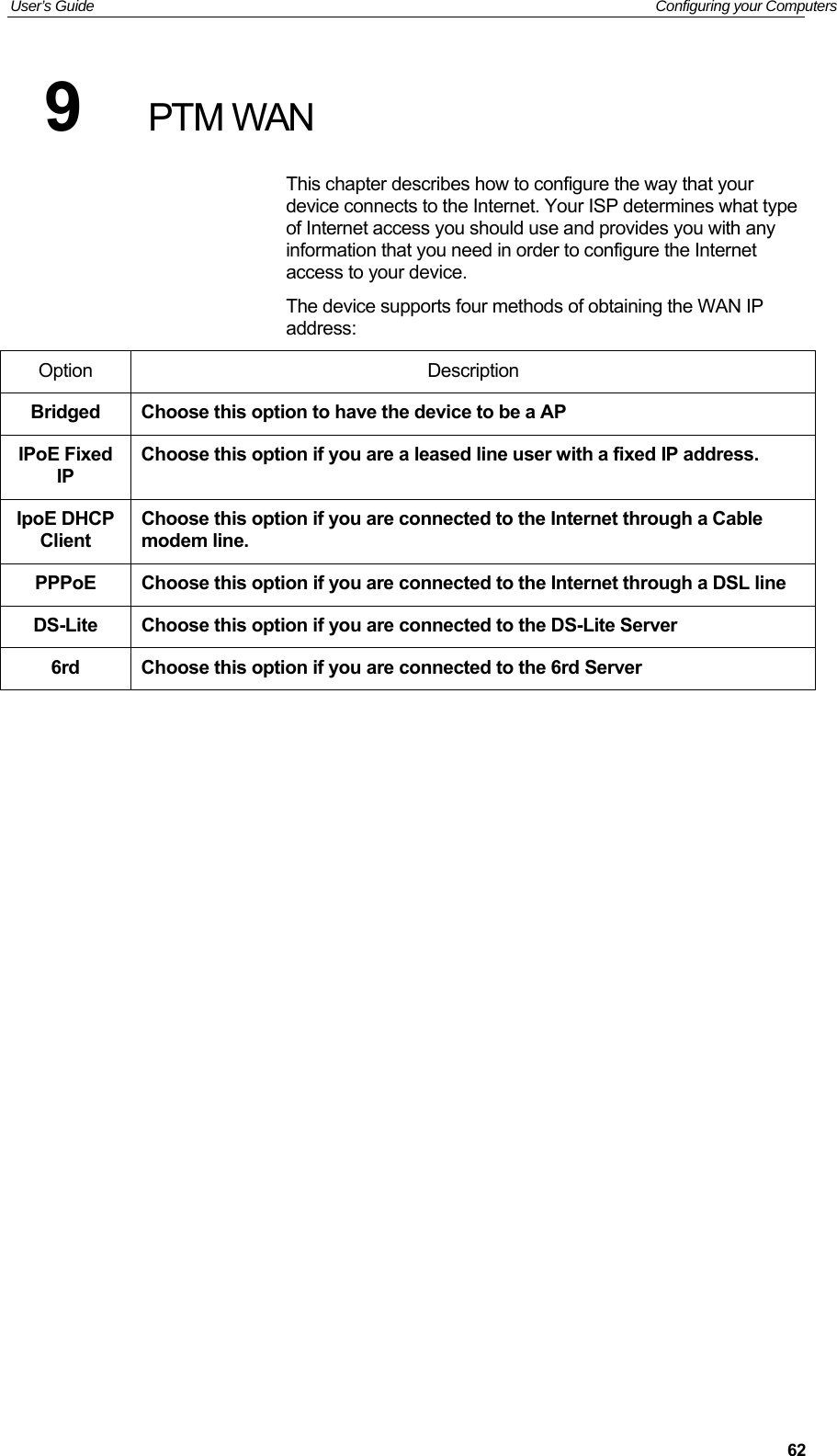
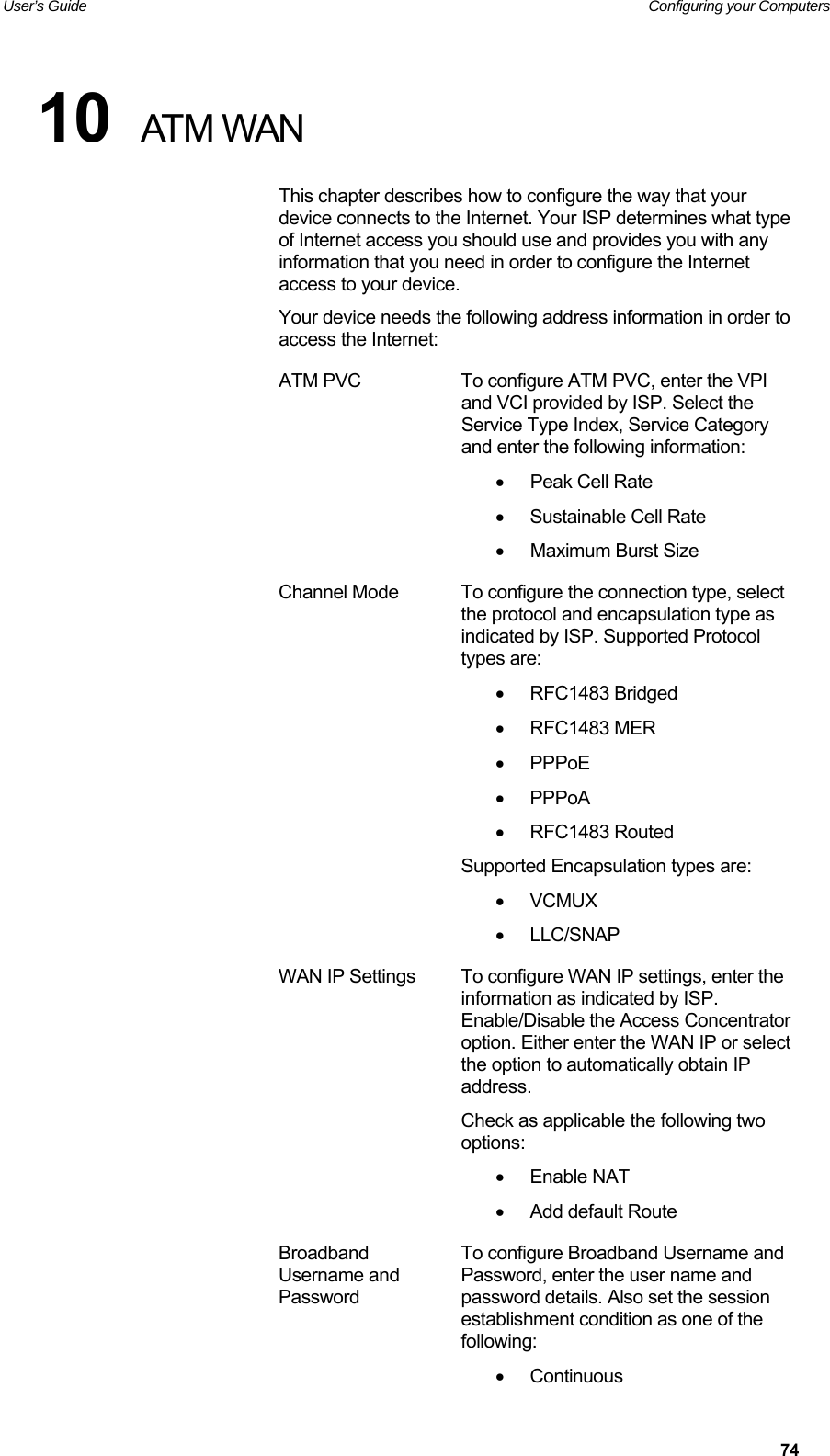
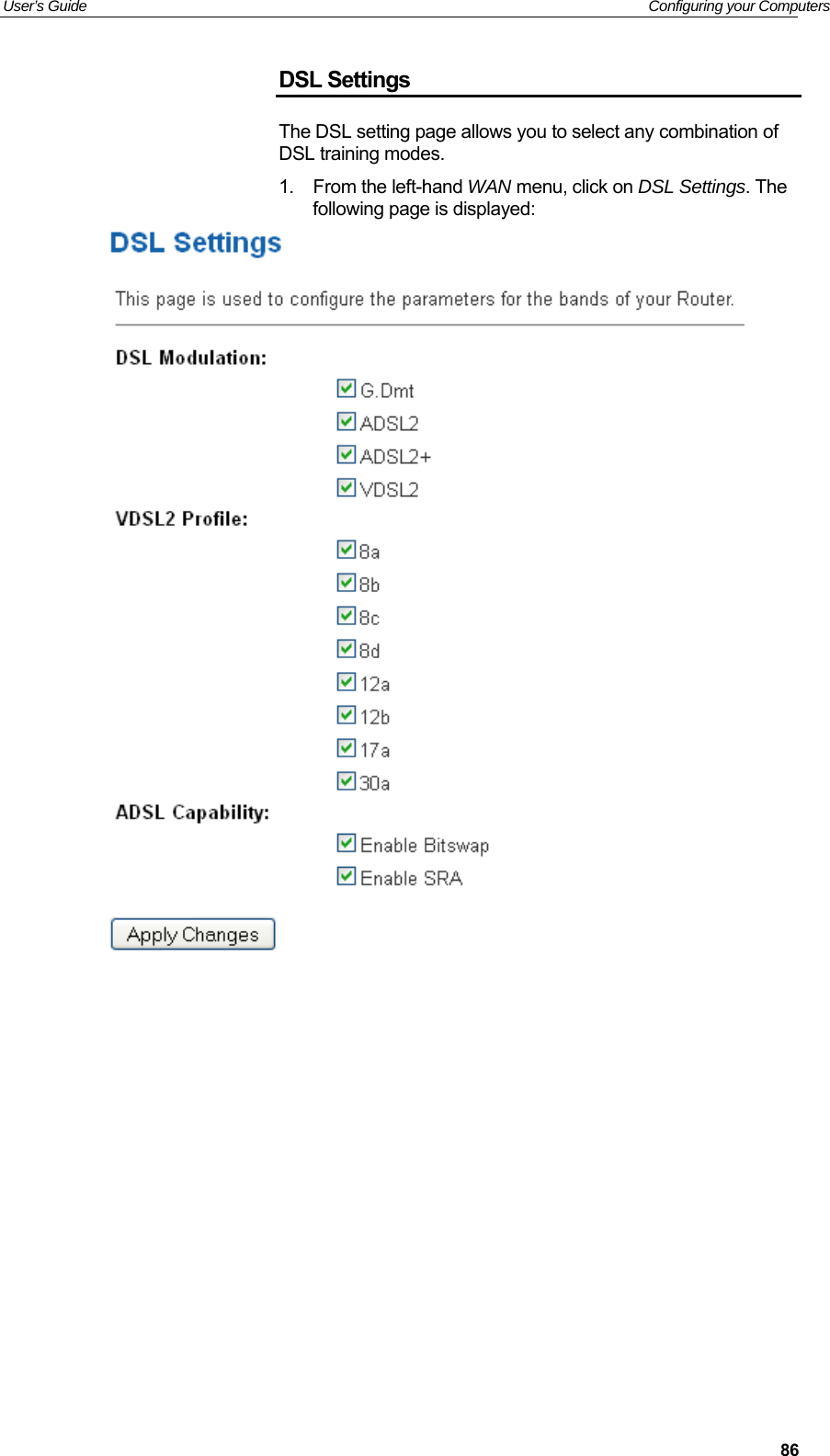
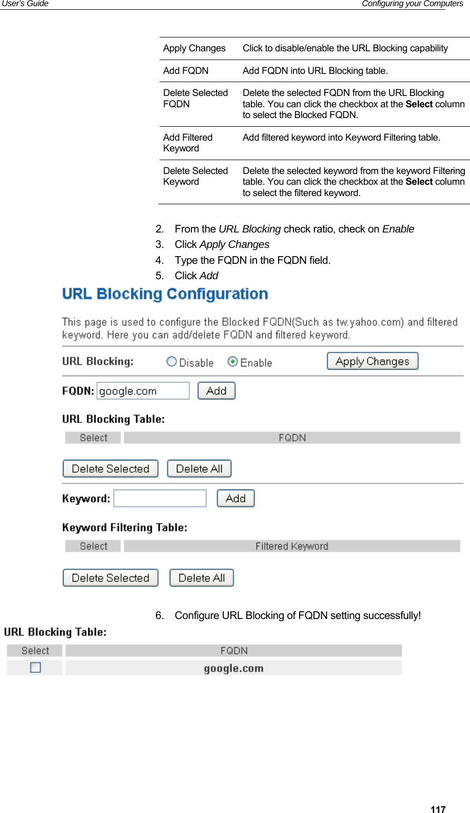
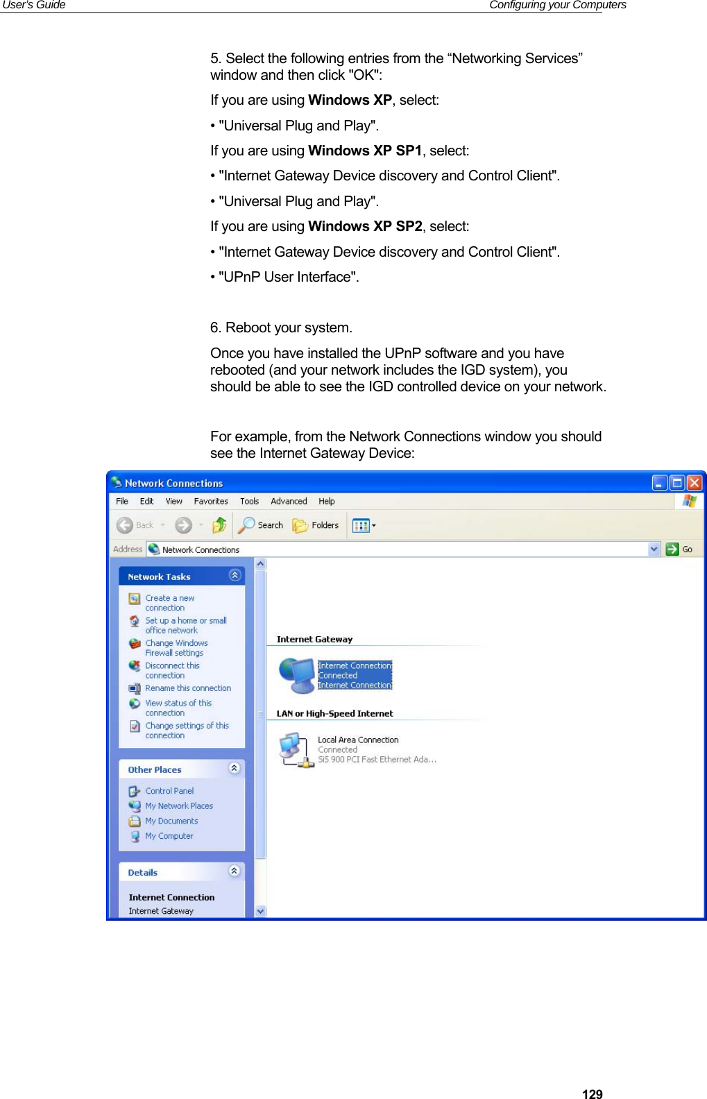
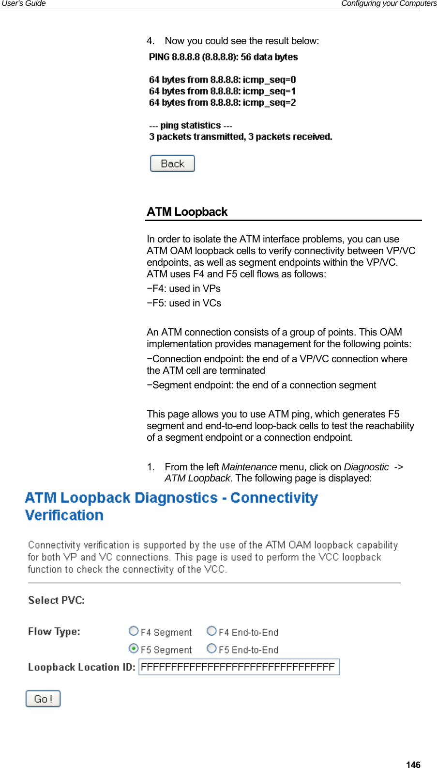
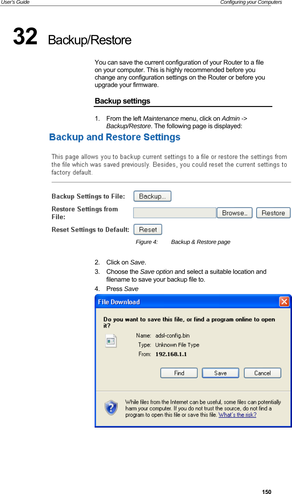
![VDSL2 Router User’s Guide 475 Getting Started with the Web pages The VDSL2 Router includes a series of Web pages that provide an interface to the software installed on the device. It enables you to configure the device settings to meet the needs of your network. You can access it through your web browser from any PC connected to the device via the LAN ports. Accessing the Web pages To access the Web pages, you need the following: A PC or laptop connected to the LAN port on the device. A web browser installed on the PC. The minimum browser version requirement is Internet Explorer v4 or Netscape v4. For the best display quality, use latest version of Internet Explorer, Netscape or Mozilla Firefox.From any of the LAN computers, launch your web browser, type the following URL in the web address (or location) box, and press [Enter] on your keyboard: http://192.168.1.1 The Status homepage for the web pages is displayed:](https://usermanual.wiki/Eltek-Technologies/V7100/User-Guide-3406525-Page-47.png)
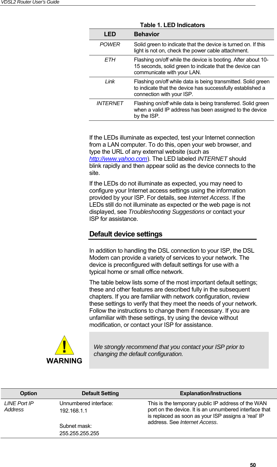
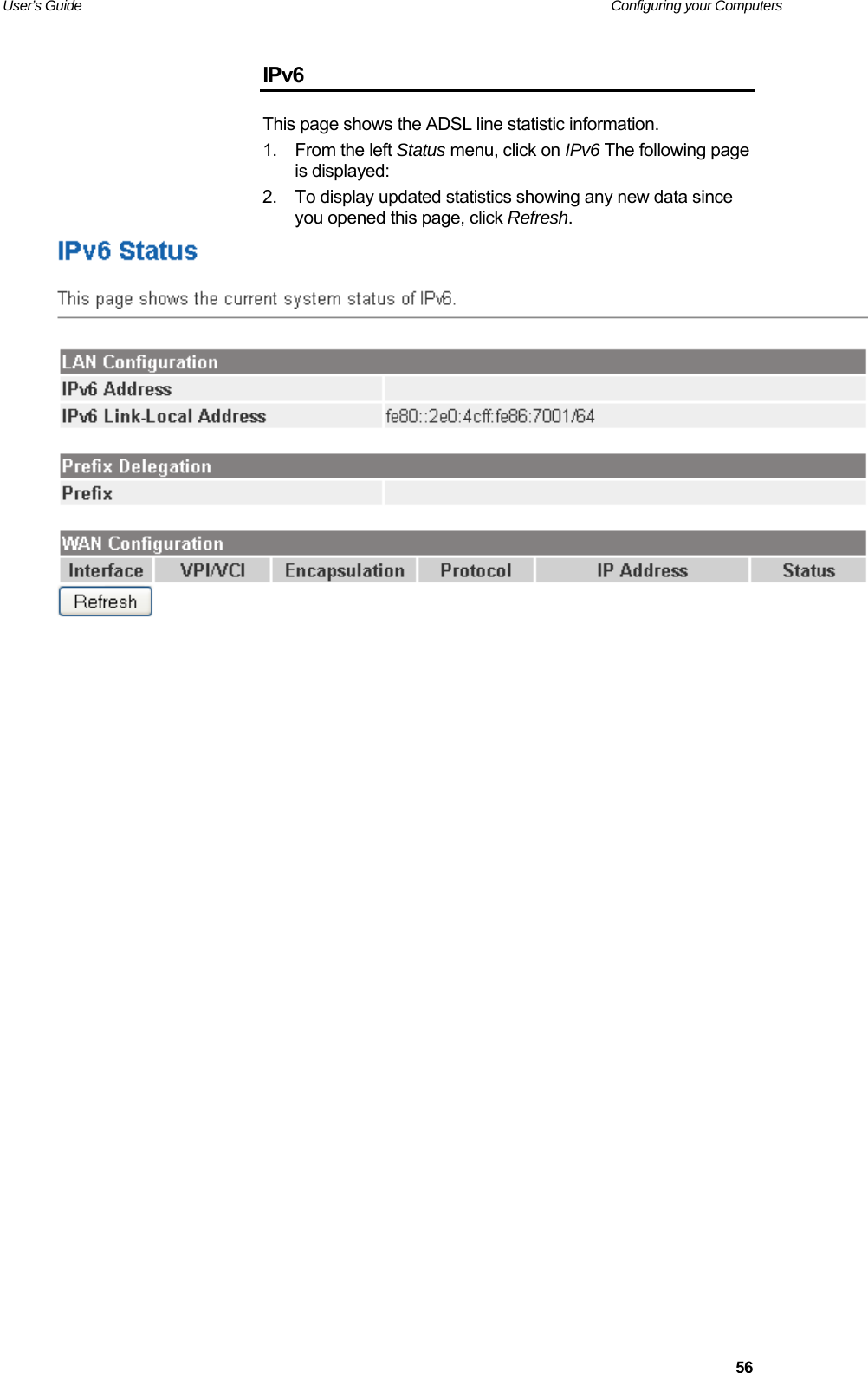
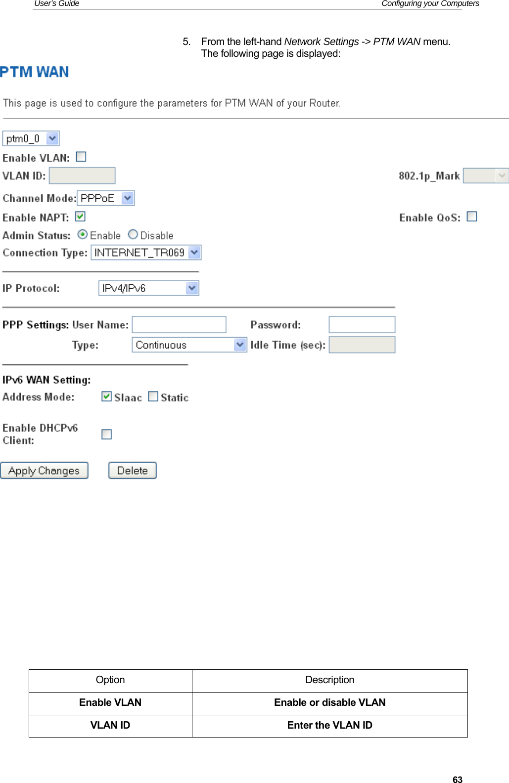
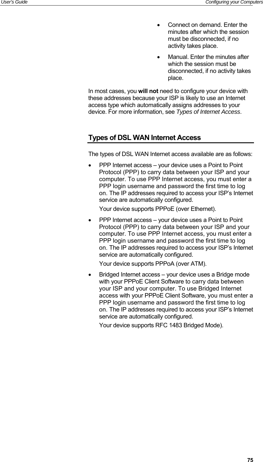
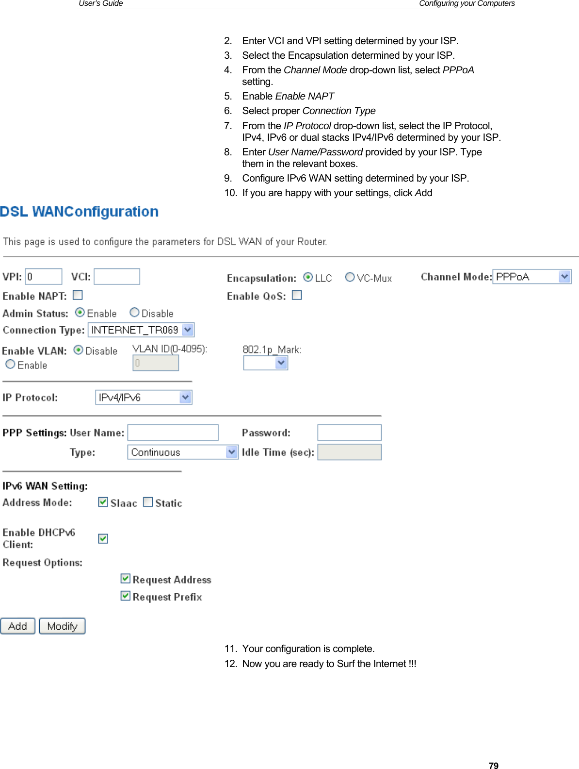
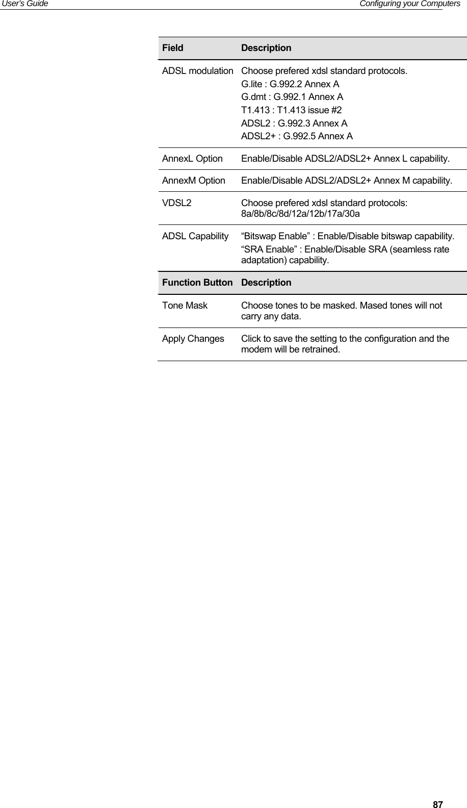
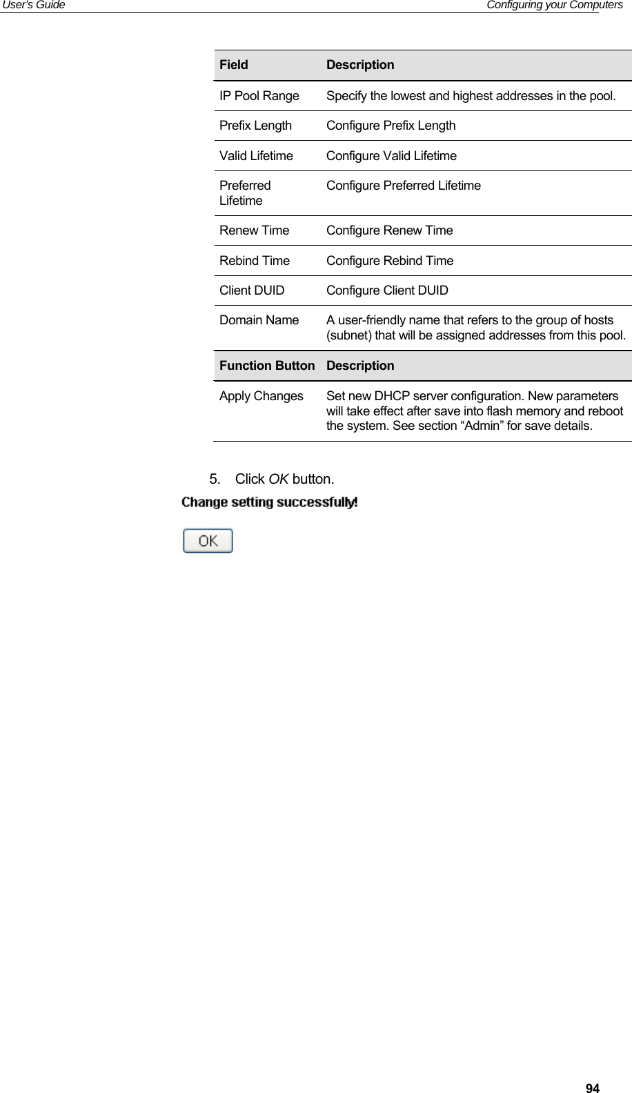
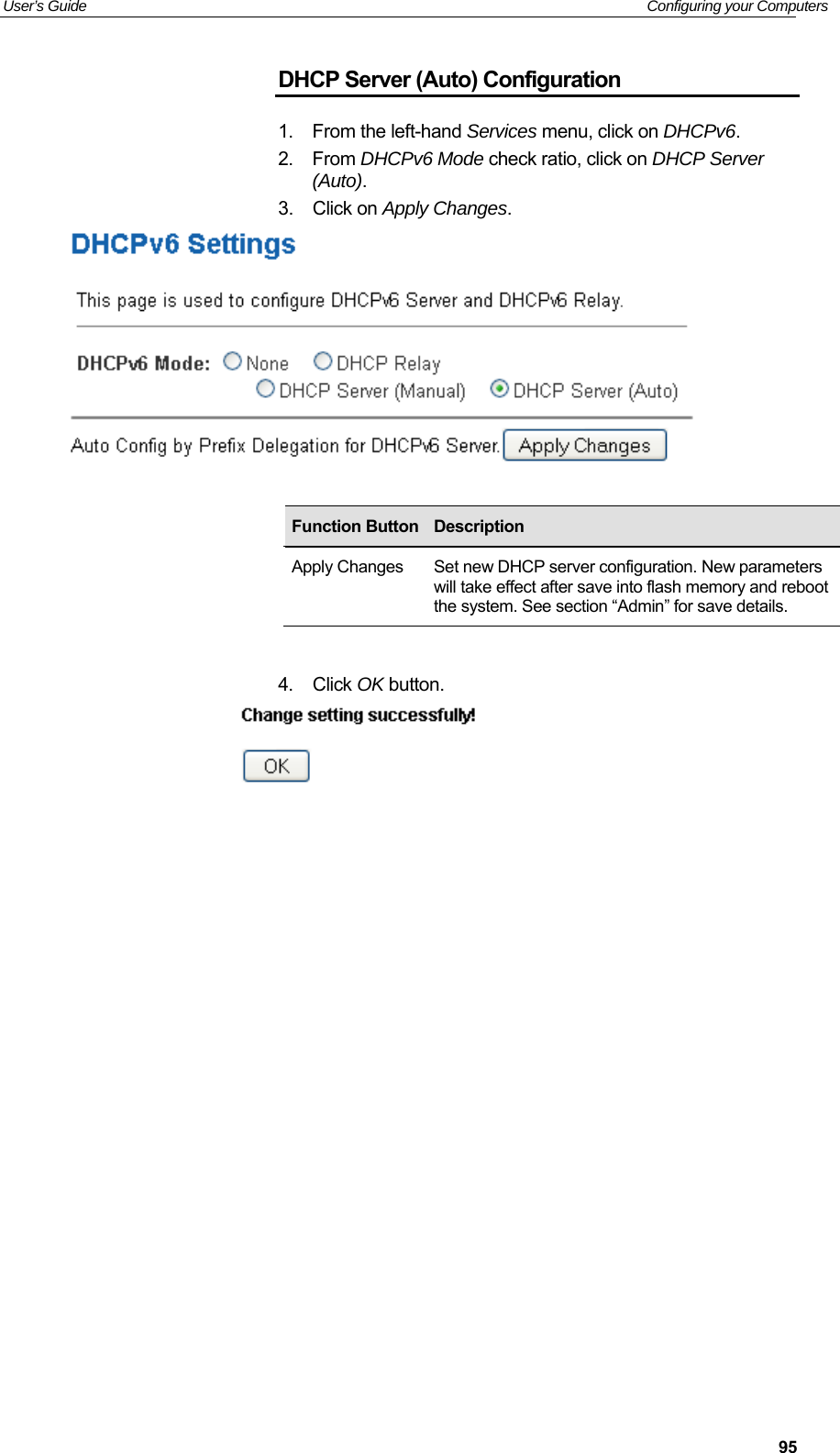
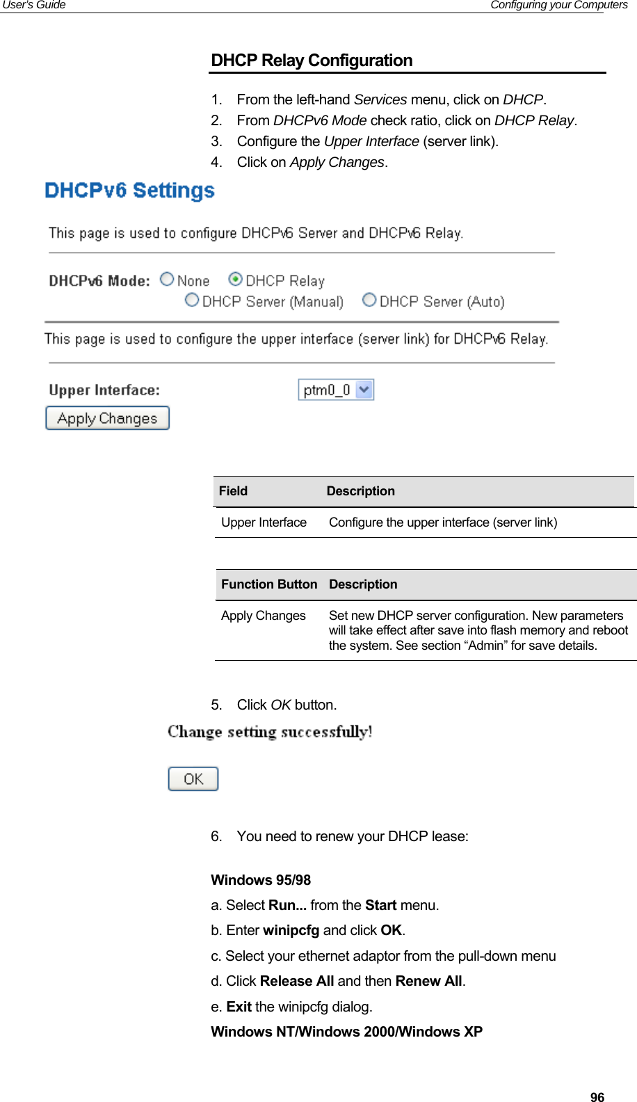
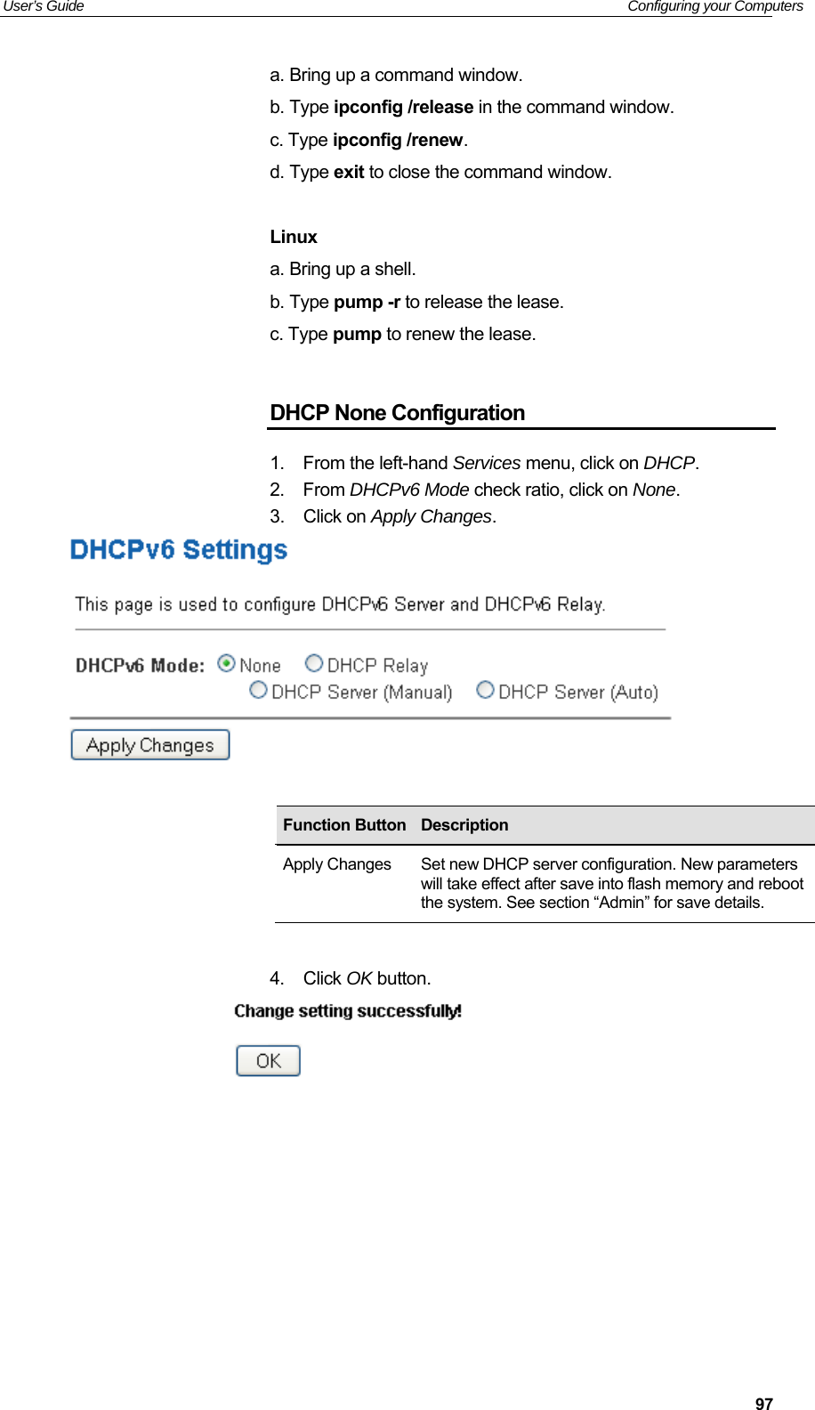


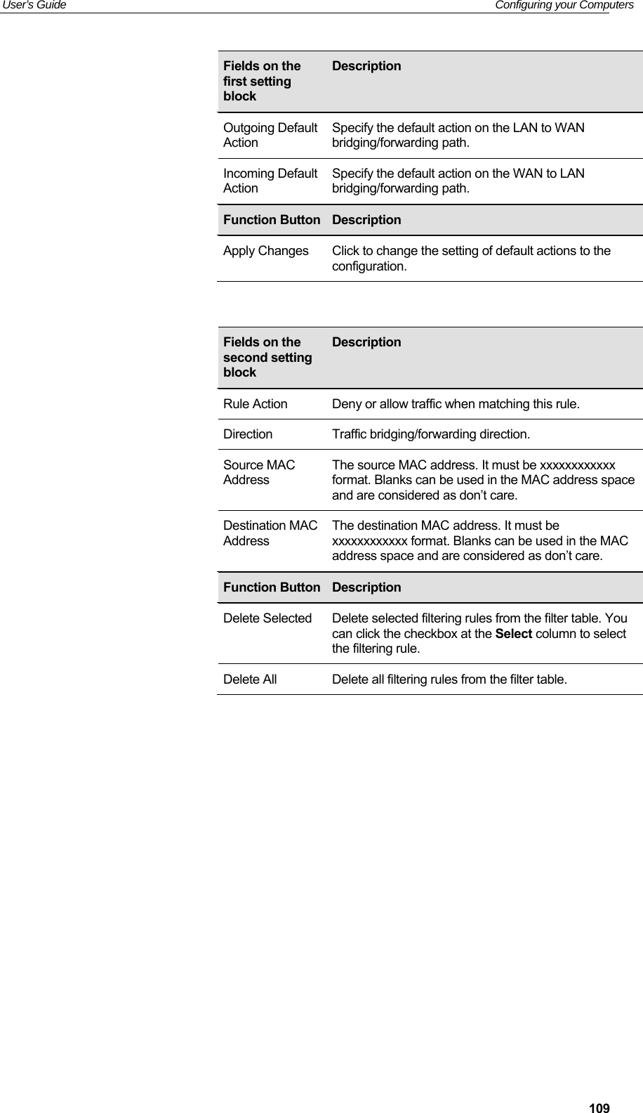
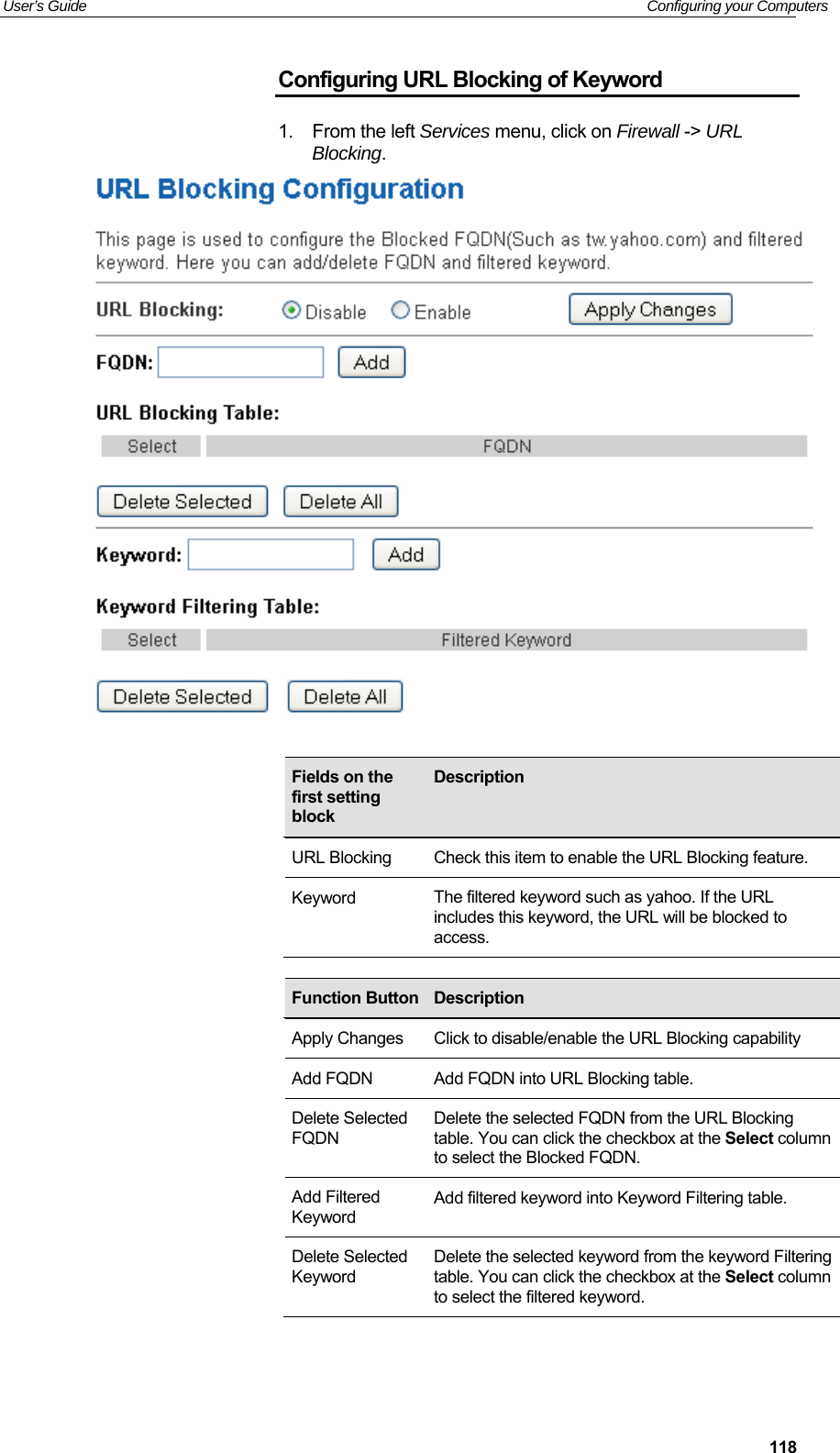
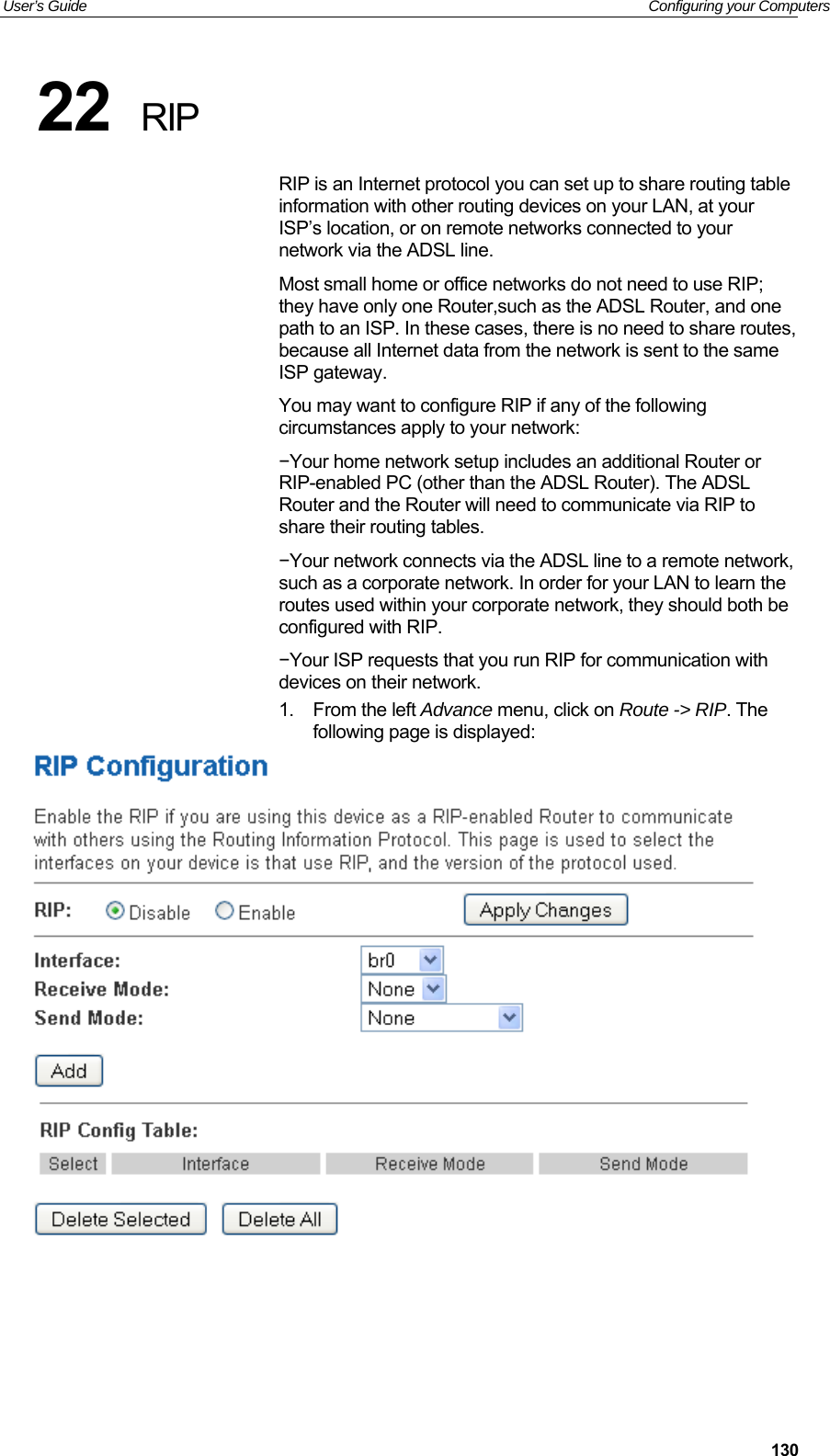
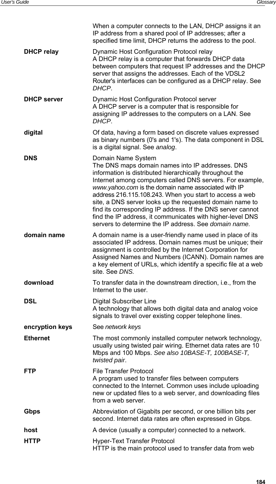
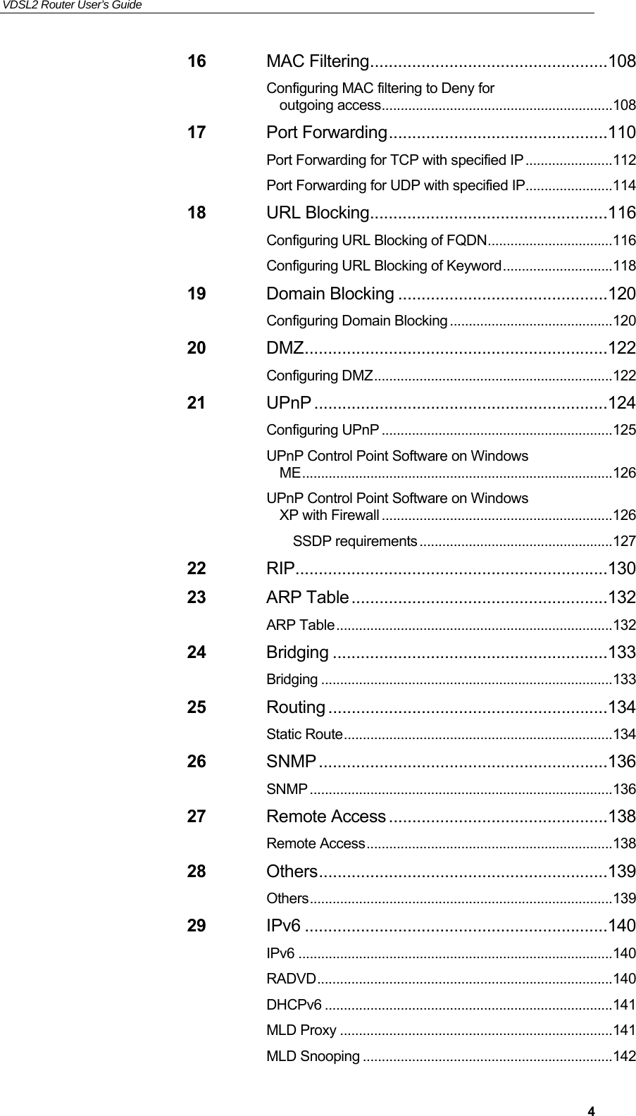
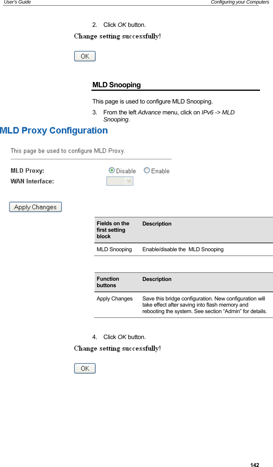
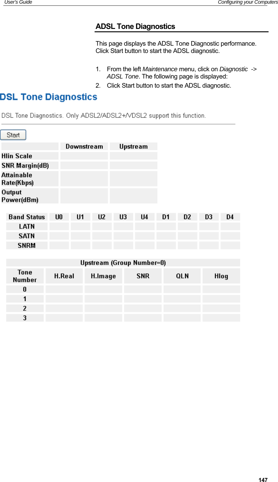
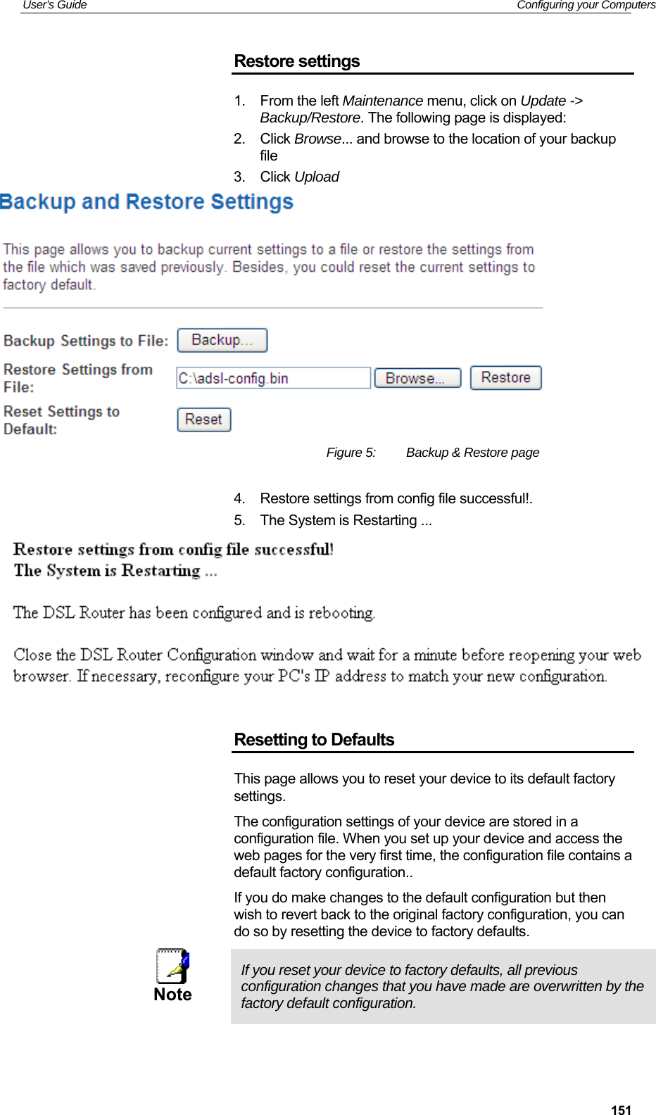
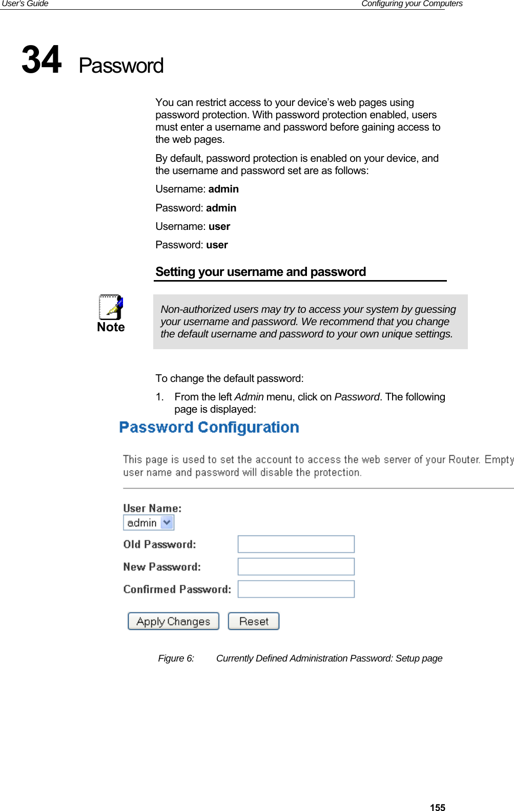
![User’s Guide Configuring your Computers 13324 Bridging You can enable/disable Spanning Tree Protocol and set MAC address aging time in this page. Bridging 1. From the left Advance menu, click on Bridging. Fields on the first setting block Description Ageing Time Set the Ethernet address ageing time, in seconds. After [Ageing Time] seconds of not having seen a frame coming from a certain address, the bridge will time out (delete) that address from Forwarding DataBase (fdb). 802.1d Spanning Tree Enable/disable the spanning tree protocol Function buttons Description Apply Changes Save this bridge configuration. New configuration will take effect after saving into flash memory and rebooting the system. See section “Admin” for details. Show MACs List MAC address in forwarding table.](https://usermanual.wiki/Eltek-Technologies/V7100/User-Guide-3406525-Page-133.png)
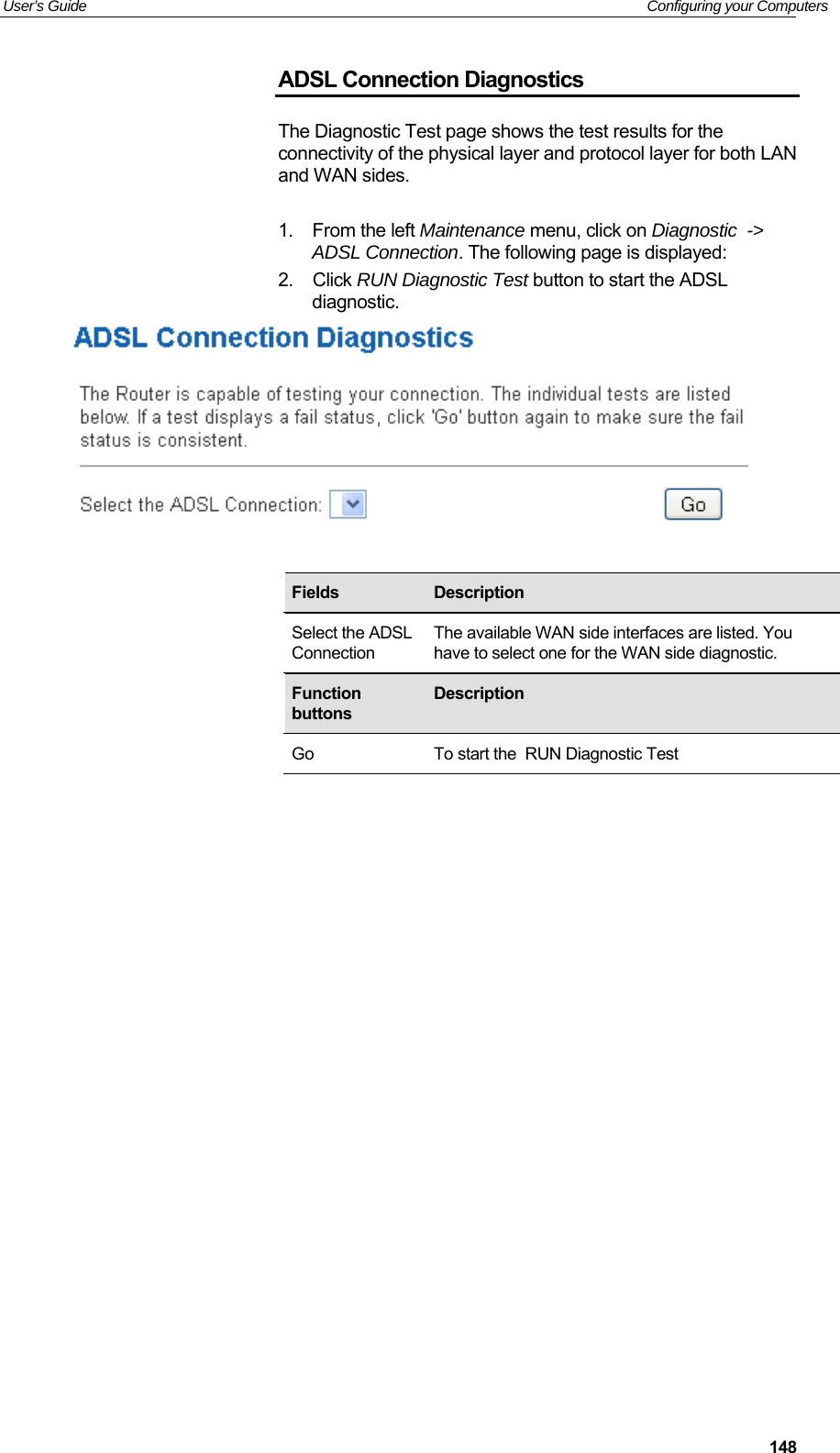
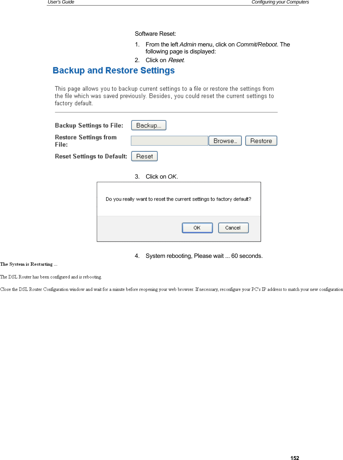
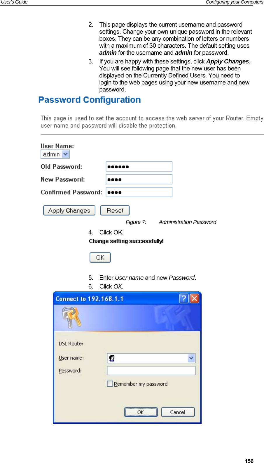

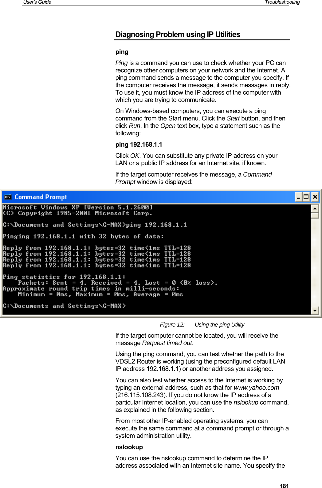
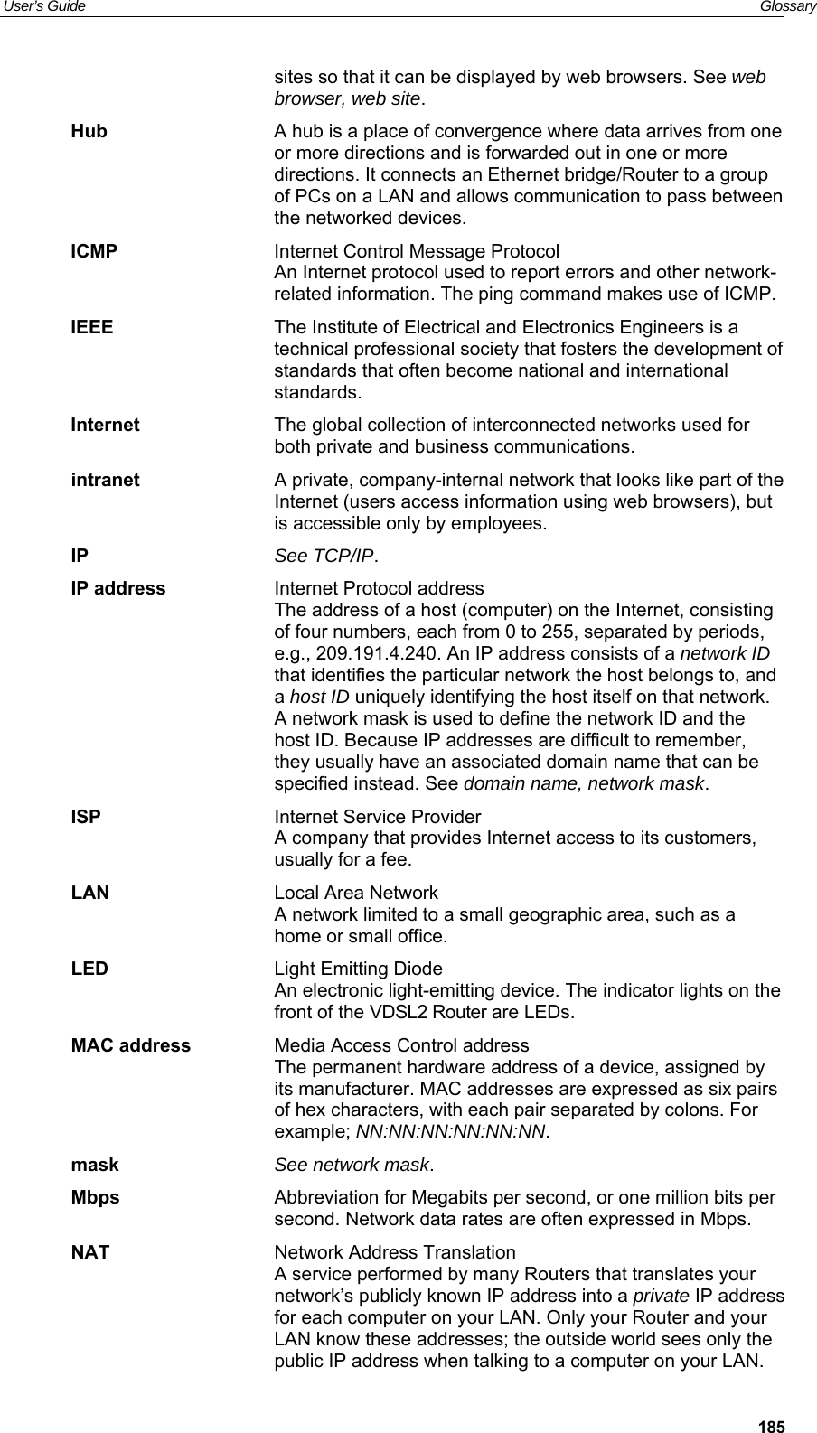
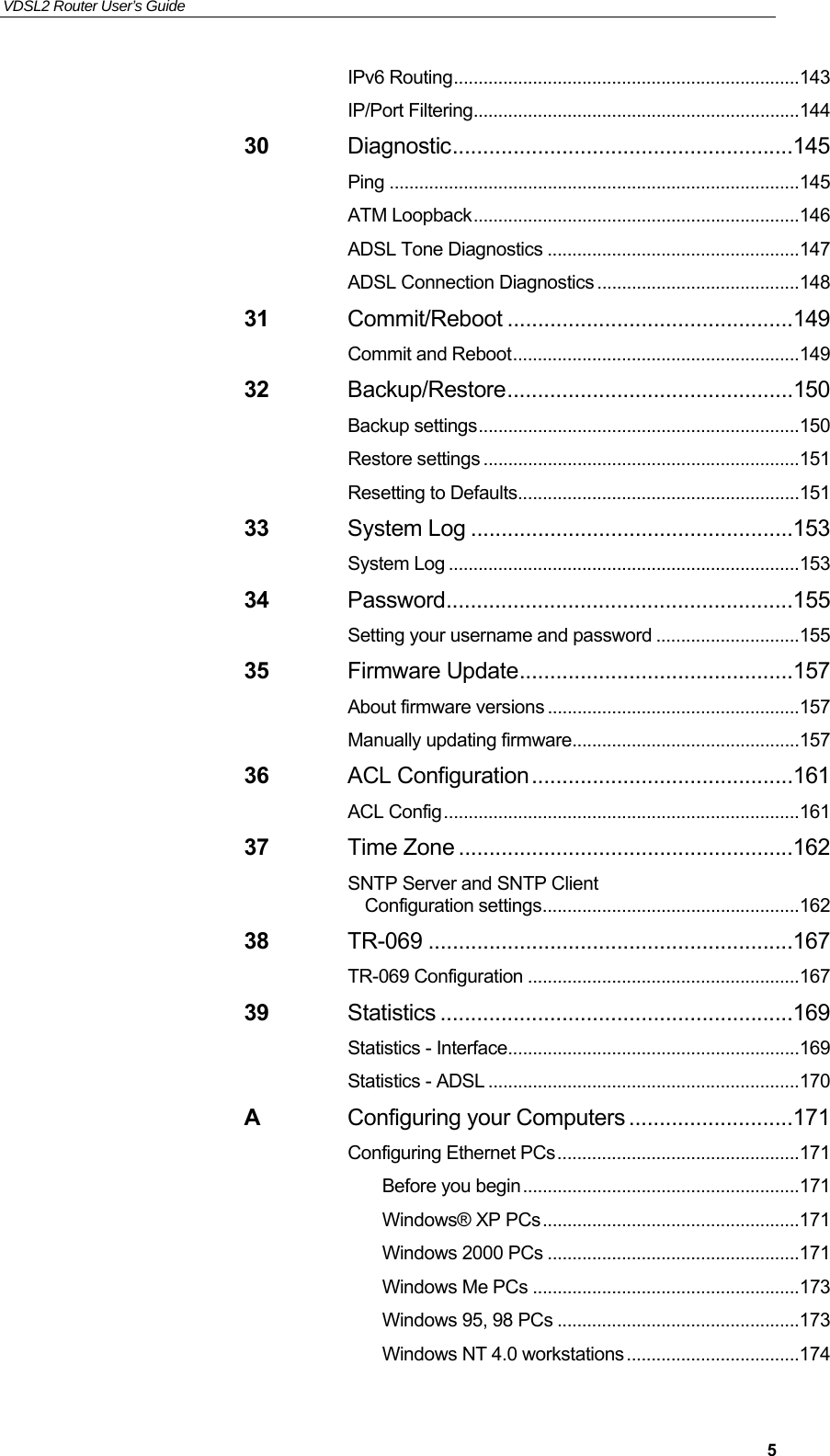
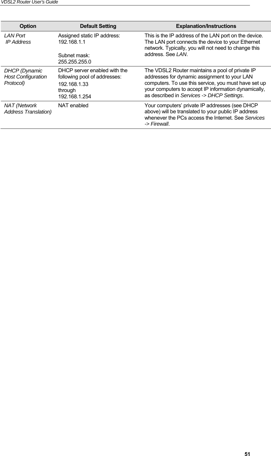
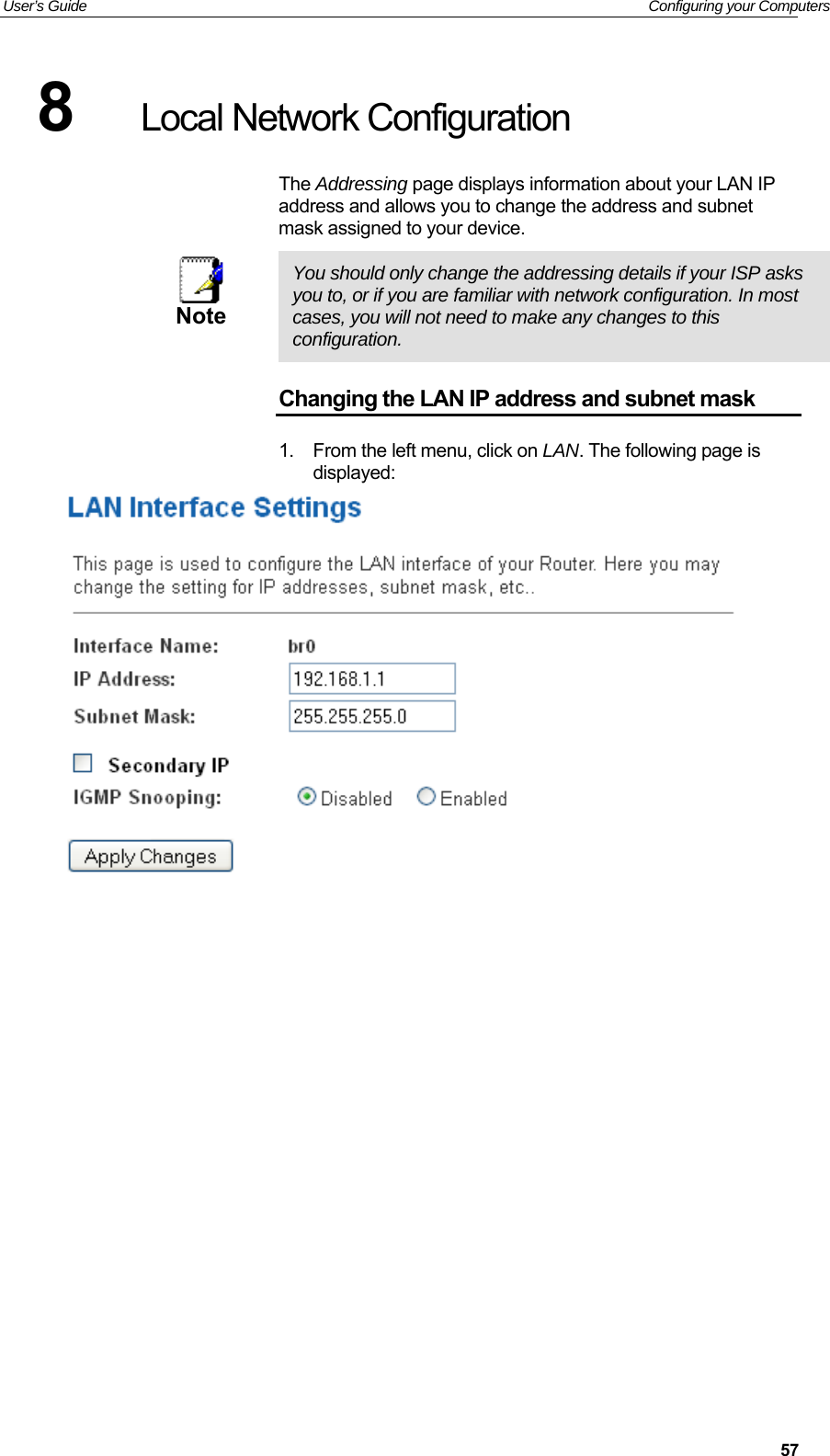
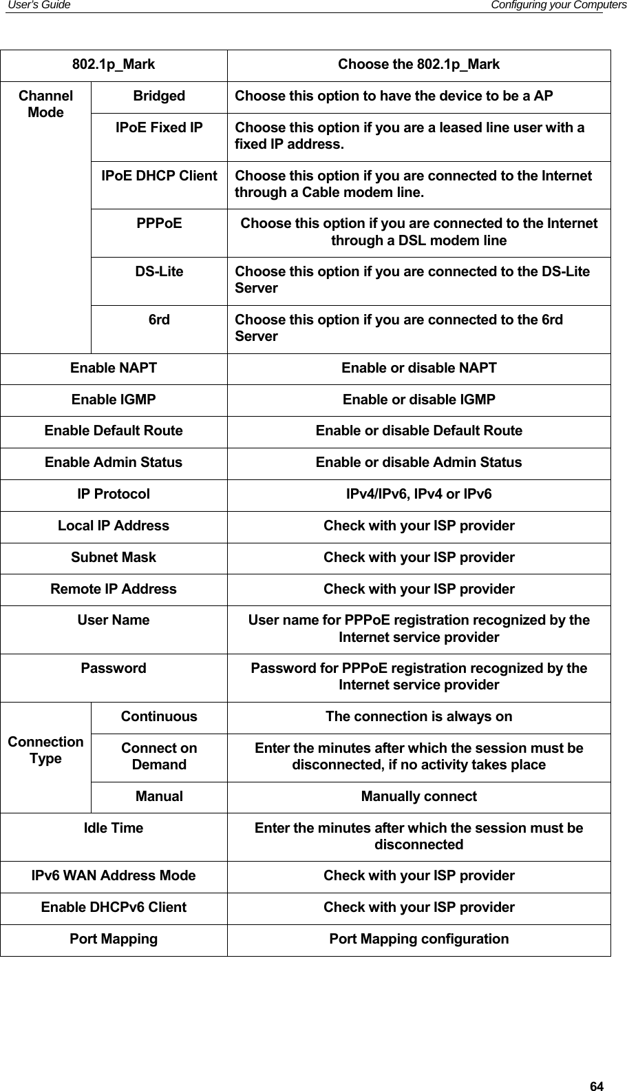
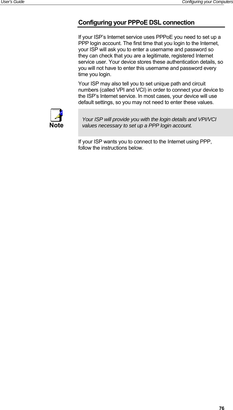
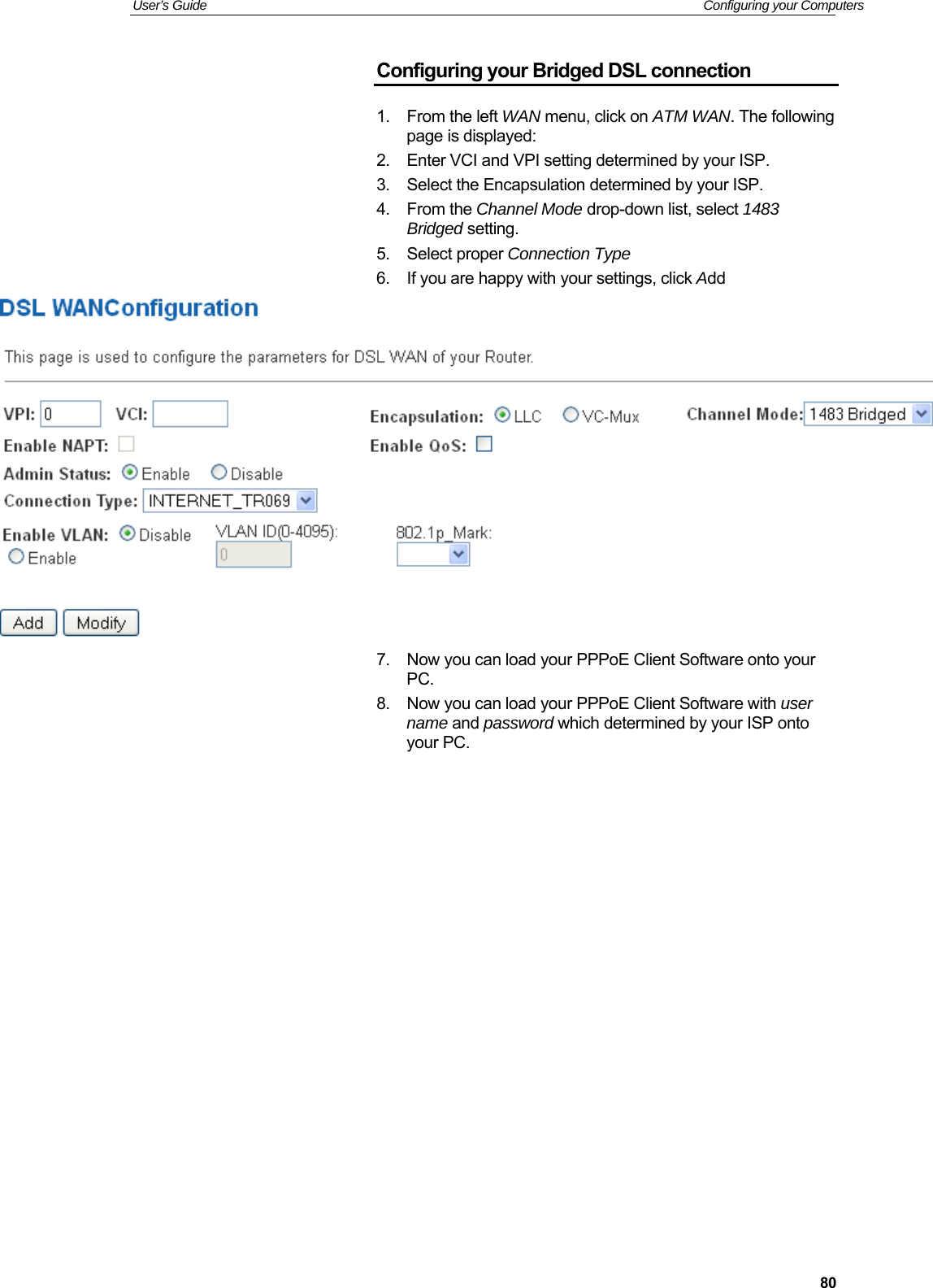
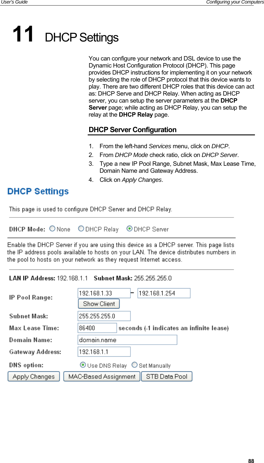
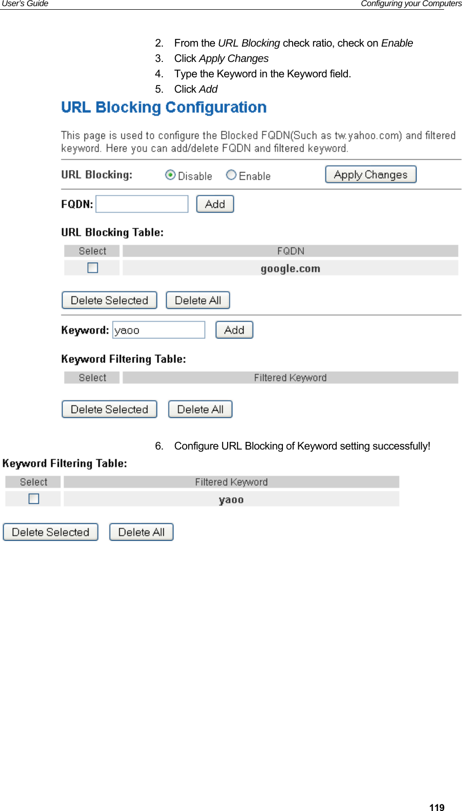
![User’s Guide Troubleshooting 182common name, and the nslookup command looks up the name in on your DNS server (usually located with your ISP). If that name is not an entry in your ISP’s DNS table, the request is then referred to another higher-level server, and so on, until the entry is found. The server then returns the associated IP address. On Windows-based computers, you can execute the nslookup command from the Start menu. Click the Start button, and then click Run. In the Open text box, type the following: Nslookup Click OK. A Command Prompt window displays with a bracket prompt (>). At the prompt, type the name of the Internet address that you are interested in, such as www.microsoft.com. The window will display the associate IP address, if known, as shown below: Figure 13: Using the nslookup Utility There may be several addresses associated with an Internet name. This is common for web sites that receive heavy traffic; they use multiple, redundant servers to carry the same information. To exit from the nslookup utility, type exit and press [Enter] at the command prompt.](https://usermanual.wiki/Eltek-Technologies/V7100/User-Guide-3406525-Page-182.png)