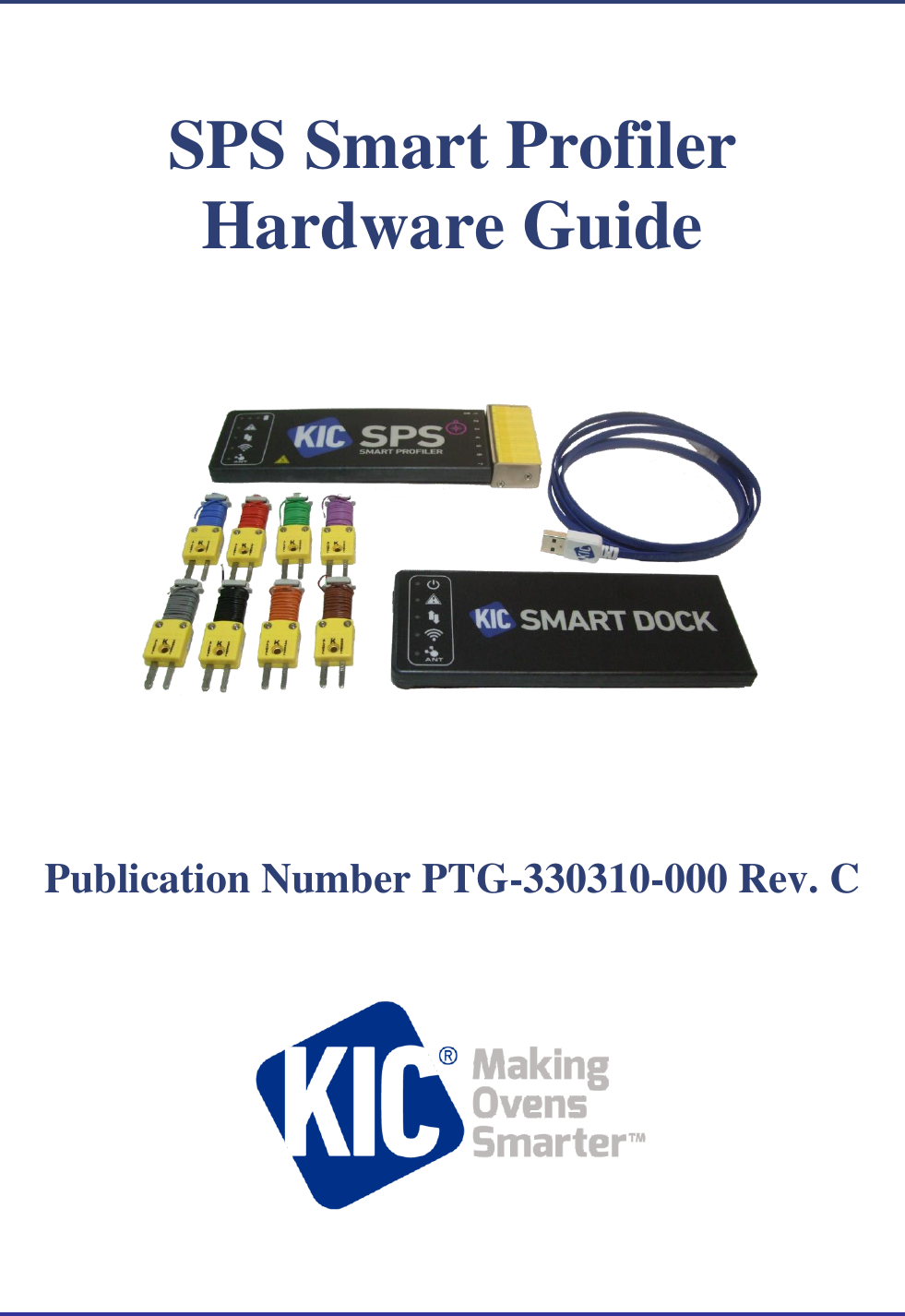
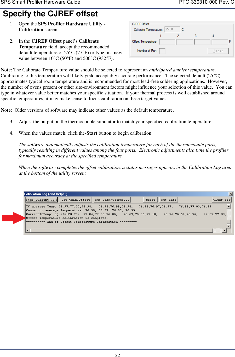
Embedded Designs KIC KIC86 THERMAL PROFILER User Manual SPS Smart Profiler Hardware Guide
Embedded Designs Inc., dba KIC THERMAL PROFILER SPS Smart Profiler Hardware Guide
UserManual.wiki
>
Embedded Designs KIC
>
KIC86 User Manual
user manual
Navigation menu
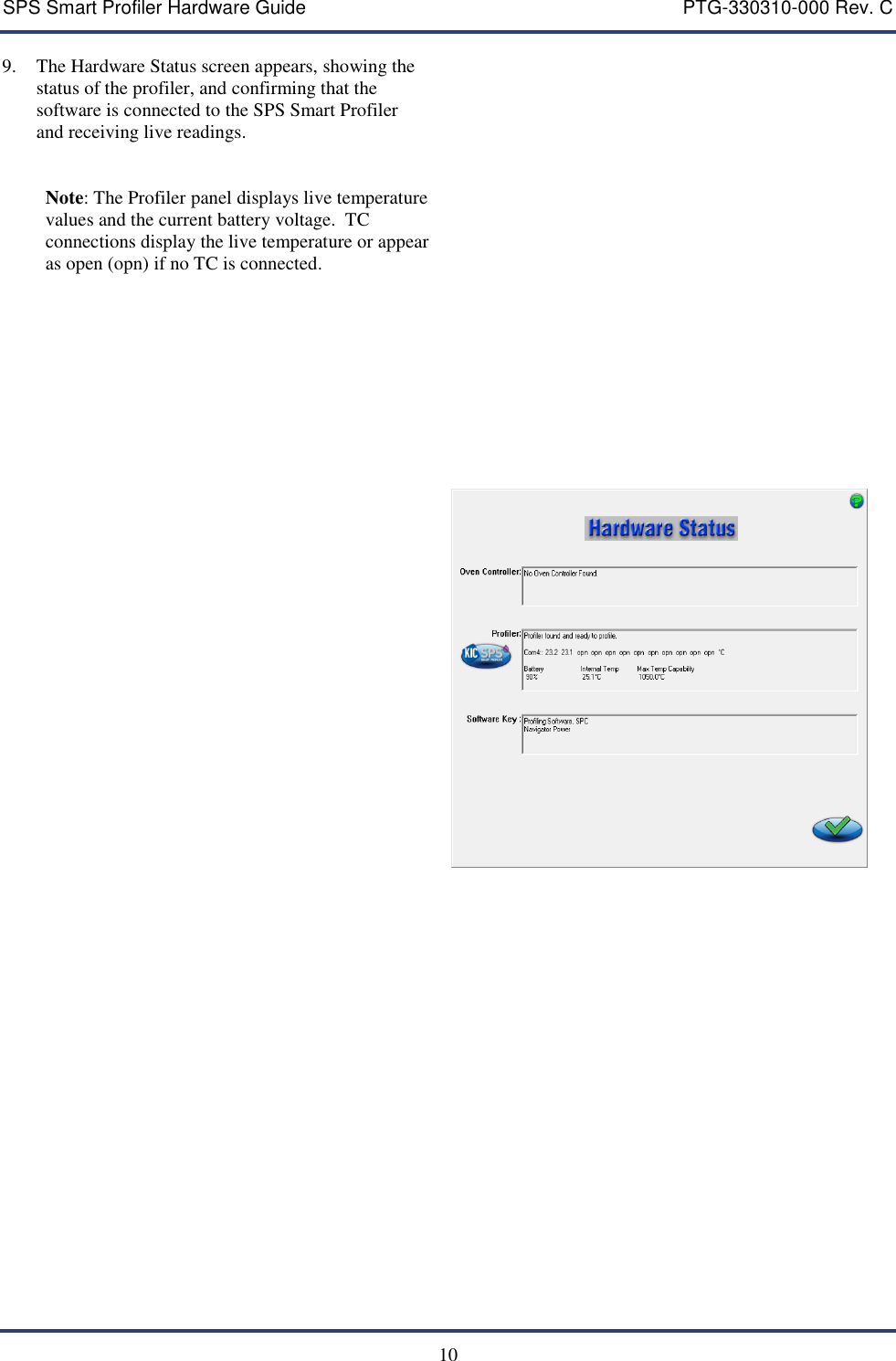
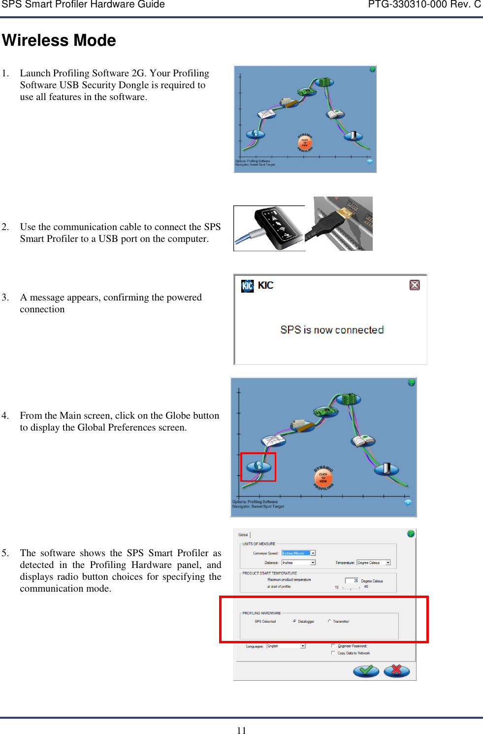
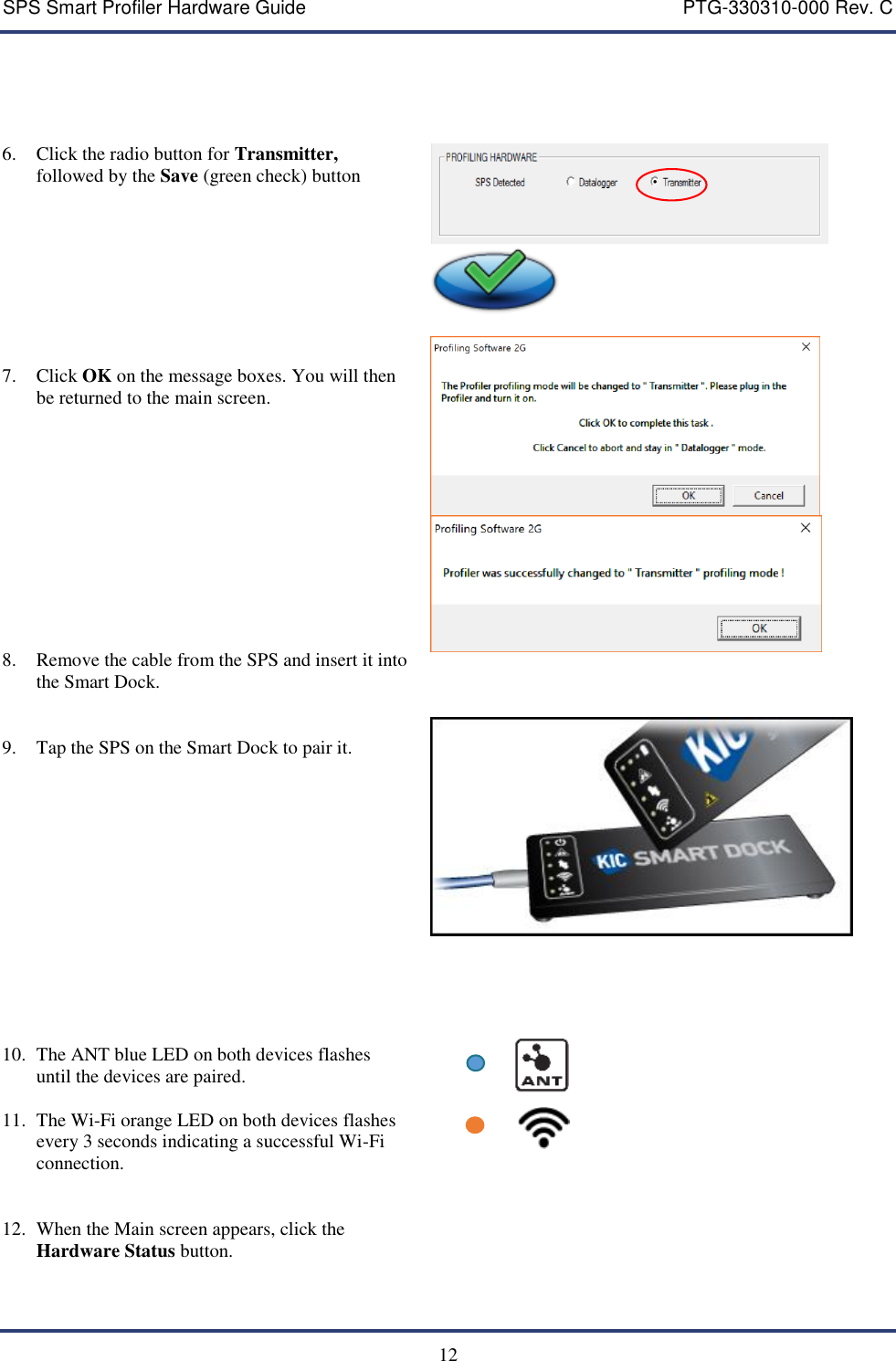
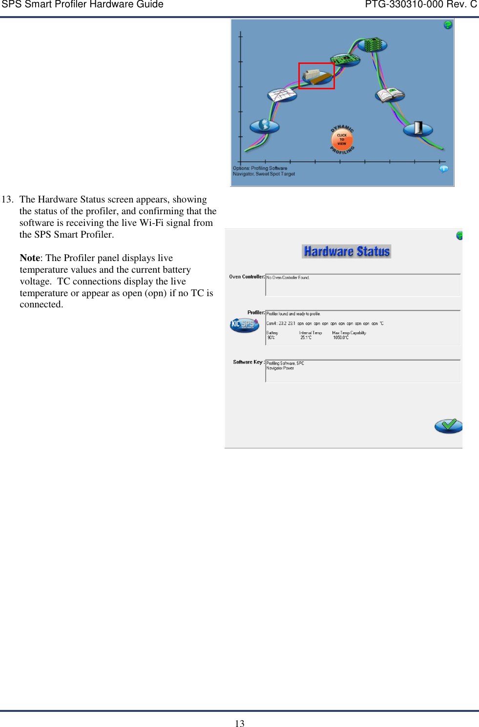
Upload a User Manual
Namespaces
Wiki Guide
HTML
PDF
Info
Views
User Manual
Discussion / Help
Navigation