Embedded Designs KIC SRA001 Thermal Profiler (Smart Reflow Analyzer) User Manual
Embedded Designs Inc., dba KIC Thermal Profiler (Smart Reflow Analyzer)
user manual
SRA Smart Reflow Analyzer
Hardware Guide
Publication Number SRA-330200-000

SRA Smart Reflow Analyzer Hardware Guide SRA-330200-000
i
SRA Smart Reflow Analyzer Hardware Guide
Copyright © 2018 KIC. All rights reserved. Patents pending.
16120 West Bernardo Drive
San Diego, CA 92127
Phone: +1 858 673 6050 Fax: +1 858 673 0085
A Division of Embedded Designs Inc.
This document contains information that is proprietary to KIC. Said information, is copyrighted as is all associated
software and hardware. All rights are reserved. Patents are pending.
This document and the information contained in it may not be sold, duplicated, used, or disclosed, in whole or in
part, except as specifically authorized in writing by KIC. The information contained in this document and
associated software is subject to change without notice.
There are no warranties with respect to the information contained in this document, express or implied, except as
provided by written contract between KIC and the customer.
All KIC product names and logos are trademarks of Embedded Designs, Inc. All other trademarks used herein are
the property of their respective owners.

SRA Smart Reflow Analyzer Hardware Guide SRA-330200-000
ii
Table of Contents
INTRODUCING THE SRA - SMART REFLOW ANALYZER ............................................................................................ 1
REVIEW YOUR SRA KIT .................................................................................................................................................... 2
YOUR SRA SOFTWARE ..................................................................................................................................................... 2
SRA HARDWARE INITIALIZATION ........................................................................................................................... 3
WARRANTY PROTECTION IMPAIRMENT ............................................................................................................................... 3
THE SRA LEDS ......................................................................................................................................................... 4
THE SMART DOCK LEDS.......................................................................................................................................... 5
THE SRA SPEED DETECTION SENSORS .................................................................................................................... 6
POWER THE SRA .................................................................................................................................................... 7
TYPICAL CHARGING TIME ................................................................................................................................................. 7
BATTERY LED BEHAVIOR .................................................................................................................................................. 7
THE POWER BUTTON ...................................................................................................................................................... 7
SET UP THE SRA ..................................................................................................................................................... 8
CHOOSING THE MODE OF PROFILING .................................................................................................................... 9
DATALOG MODE ............................................................................................................................................................ 9
WIRELESS MODE .......................................................................................................................................................... 12
HARDWARE STATUS: LED STATUS WINDOW ..................................................................................................................... 15
THERMAL PROTECTION ........................................................................................................................................ 16
SAFE HANDLING AFTER EXITING THE OVEN ......................................................................................................... 17
SAFELY REMOVE THE SRA FROM THE OVEN ....................................................................................................................... 17
SAFELY OPENING THE SHIELD .......................................................................................................................................... 18
SPECIFICATIONS AND NORMAL ENVIRONMENTAL CONDITIONS ......................................................................... 19
CLEANING PROCEDURE .................................................................................................................................................. 19
REGULATORY COMPLIANCE ................................................................................................................................. 20
CALIBRATING THE SRA ......................................................................................................................................... 21
REMOVE SRA MODULE ................................................................................................................................................. 22
ESTABLISH COMMUNICATION .......................................................................................................................................... 22
SPECIFY THE CJREF OFFSET ............................................................................................................................................ 24
SPECIFY THE GAIN ADJUSTMENT ....................................................................................................................................... 25
REINSTALL SRA MODULE ............................................................................................................................................... 26
CONTACT KIC ....................................................................................................................................................... 27
SRA Smart Reflow Analyzer Hardware Guide SRA-330200-000
1
Introducing the SRA - Smart Reflow Analyzer
Built with the latest data processing and wireless technologies available – a smart device
The SRA (Smart Reflow Analyzer) and Smart Dock are packed with the latest in data processing and wireless
technologies.
Sampling capabilities up to 50 readings per second
Real-time data collection through a secure, private Wi-Fi network with the Smart Dock pairing using ANT
technology
The latest in durable high temperature rated materials.
NiMH rechargeable batteries make for a reliable and safe power source
Advanced sensors for automated conveyor speed measurements
Profile Stacking: Store multiple profile runs in a row before downloading
The SRA Smart Reflow Analyzer stands out as the best and “smartest” temperature data collection system available.
The hardware is the best in temperature tolerance design using an LCP (Liquid Crystal Polymer) enclosure for
better protection and faster cooldown between profiles. The design of the SRA thermal shield allows for easy and
secure opening and closing, durability that meets the most stringent of drop tests, and temperature tolerance
capabilities that exceed all previous KIC profiler and shield models.
Thermal profile data are conveniently transferred to your computer via a USB connection or real-time via Wi-Fi
depending on the model. With complex power management algorithms and state-of-the-art circuitry, the SRA
allows for long use between charges and longer battery life. Recharging and powering can be done via the USB
cable when connected to a computer or to a wall socket.
The SRA Smart Reflow Analyzer raises the bar for Smart Factory systems and is another of the many smart devices
and systems KIC offers to improve your production quality, productivity, and documentation.
Refer to this hardware guide for additional information when you see this warning symbol.
This symbol indicates HOT SURFACE on the SRA shield and pallet. It is used in this guide anywhere
where warnings are indicating safety procedures or warnings concerning hot surfaces.
SRA Smart Reflow Analyzer Hardware Guide SRA-330200-000
2
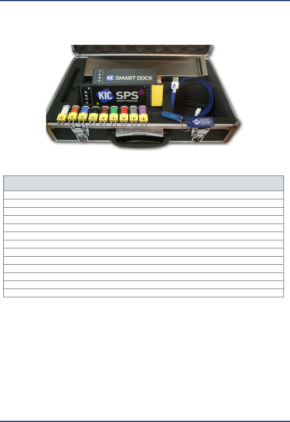
Review Your SRA Kit
Upon receiving your SRA kit, check it to make sure that all the required components are there. The specific contents
of your kit will match the configuration— datalog or wireless—that you ordered. The full catalog of parts appears
below.
NEED NEW IMAGE OF COMPLETE KIT ABOVE
Part Description
SRA Smart Reflow Analyzer - datalog or Wi-Fi model
Smart Dock (Wi-Fi models only)
AC charger/power supply
USB communication cable (A-Male/Micro-B)
Gloves for handling the SRA, hot from the thermal process
SRA Smart Reflow Analyzer Getting Started Guide
SRA Smart Reflow Analyzer CD containing:
Profiling Software 2G
SRA Smart Reflow Analyzer Hardware Guide
Profiling Software 2G User Manual
USB Software Dongle Key (Needed to run the Profiling Software 2G )
Calibration Certificate
Carrying Case
Your SRA Software
Profiling Software 2G provides all the tools you need for thermal profiling with your SRA Smart Reflow
Analyzer. It lets you set operating parameters, monitor your hardware, graphically display analytical data, and manage
multiple profile data sets. This Hardware Guide uses images from the Profiling Software 2G to illustrate procedures.

SRA Smart Reflow Analyzer Hardware Guide SRA-330200-000
3
SRA Hardware Initialization
To begin profiling in either datalog or Wi-Fi mode, you must first set up your SRA for use on your PC. Both modes
communicate to the computer through a standard USB port – datalog mode uses a cable, Transmitter (Wi-Fi) mode
uses the Smart Dock. If the computer has no available USB ports, use a standard 2-8 port hub to add an open port.
Note: Install Profiling Software 2G BEFORE connecting the SRA Smart hardware to the computer.
Connecting the hardware before the software is installed may result in Windows OS selecting the
incorrect driver for the device and it will not connect to the software.
The normal setup routine must follow the sequence shown below:
1. Install the software.
2. Install the USB security dongle.
3. Connect the SRA Smart Reflow Analyzer hardware to the computer.
Note: When connecting the SRA Smart Reflow Analyzer to laptop computers that utilize a floating
ground connection (2-prong power plug) manually ground the laptop before connecting the SRA. This
procedure will prevent unwanted electrical interference that may distort the temperature data collected
by the SRA.
If you have any questions or need assistance connecting your hardware, contact KIC Technical Support
tech@kicmail.com.
Warranty Protection Impairment
Caution: RISK OF VIOLATION OF WARRANTY
Improper handling may limit our liability for damage to equipment and may also violate your
instrument warranty. As well improper handling or use could impair the protection provided by
the equipment.
SRA Smart Reflow Analyzer Hardware Guide SRA-330200-000
4
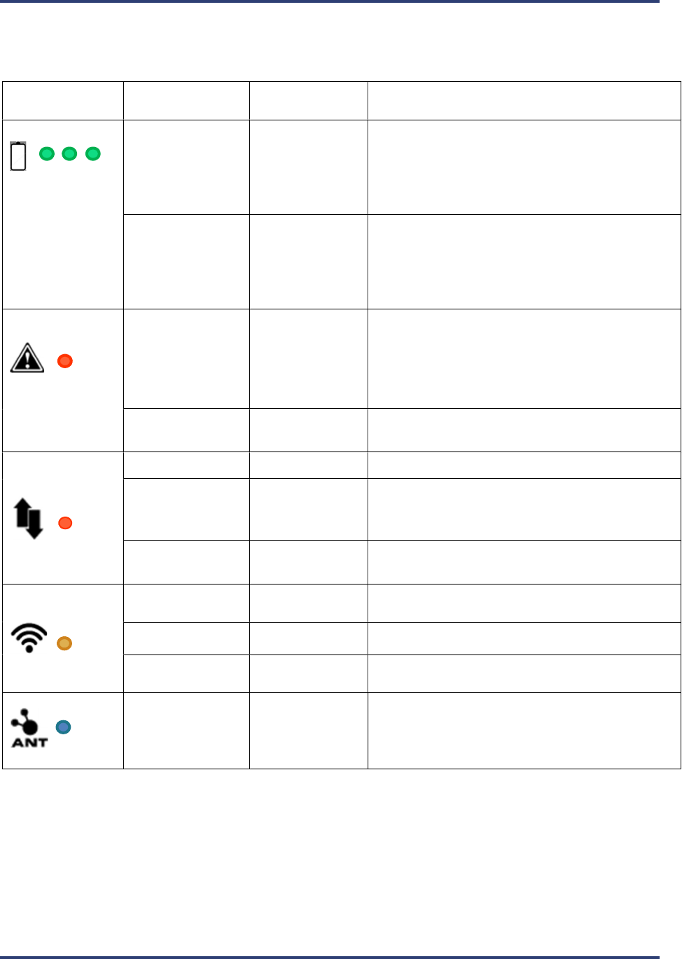
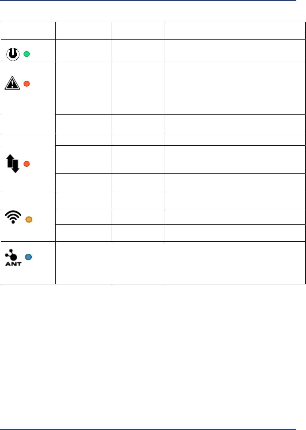
The SRA LEDs
LED Name/
Icon/Color
Mode
LED Behavior
Mode Description
Battery
Charging
Combined solid
and flashing.
See description
Plugged into USB for
charging.
Each LED represents 1/3rd of battery capacity.
Starting from the left the lights go from
flashing to solid as the battery charge fills.
Full charge when all 3 are solid.
Using battery
power
Flashing every 3
seconds
LEDs will flash depending
on amount of charge
left.
Minimum to 1/3rd charge left – LED 1
1/3rd to 2/3rd charge left – LED 1-2
2/3rd to full charge left – LED 1-2-3
Alert
Not Ready Solid On
Cannot profile: TCs too hot, SRA Module too
hot, Battery too low, startup failure, voltage
too low to charge or memory full. Plug into PC
and software to identify alert.
Ready Off Ready to begin profiling.
Data Collection
Profiling Fast Flashing Profiling in progress.
Profile Complete Flashing every 3
seconds
One or more profiles are complete and stored
in memory.
Data Empty Off No profiles stored in memory.
Wi-Fi
No
Communications
Off
Wi
-
Fi not in use or not available.
Wi
-
Fi In Use
Fast flashing
When profiling or downloading.
Wi
-
Fi Ready
Slow flashing
Flashing
every 3 seconds when paired with
Smart Dock
Beacon
Flashing
Beacon mode starts when
one sensor
window
is covered for >5 seconds. LED flashes until
SRA finds a Smart Dock beacon and pairs with it
to make private Wi-Fi connection.
SRA Smart Reflow Analyzer Hardware Guide SRA-330200-000
5
The Smart Dock LEDs
LED Name/
Icon/Color
Mode
LED Behavior
Mode Description
Power
Power
Solid
Power to Smart Dock from USB established
Alert
Not Ready Solid On
Cannot profile: due to TC 1 missing, TCs too
hot, SRA module too hot, Battery too low,
startup failure, voltage too low to charge or
memory full. Plug into PC and software to
identify alert.
Ready Off Ready to begin profiling.
Data Collection
Profiling Fast Flashing Profiling in progress.
Profile Complete Flashing every 3
seconds
One or more profiles are complete and stored
in SRA memory.
Data Empty Off No profiles stored in SRA memory.
Wi-Fi
No
Communications
Off
Wi
-
Fi not in use or not available.
Wi
-
Fi In Use
Fast flashing
When profiling or downloading.
Wi
-
Fi Ready
Slow
flashing
Flashing every 3 seconds when paired with
Smart Dock
Beacon
Flashing
Beacon mode starts when
device is tapped
.
LED flashes for 30 seconds waiting for
compatible device to pair. During this time
Smart Dock will automatically pair with a
compatible device within range.
SRA Smart Reflow Analyzer Hardware Guide SRA-330200-000
6
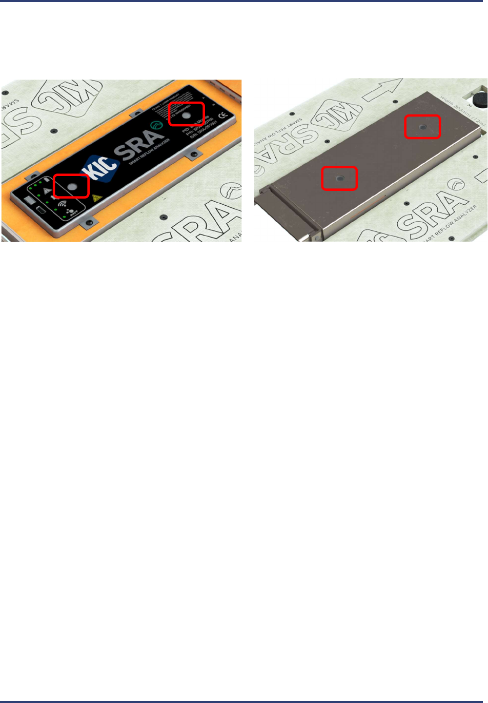
The SRA Speed Detection Sensors
The SRA uses two (2) built-in sensors for automatic calculation of the conveyor speed during a profile. The top of
the thermal shield has two access windows for these two sensors to project through when the shield lid is closed.
These sensors serve two (2) functions:
Primary use - Automatically calculate conveyor speed during profiling
Secondary use – With Wi-Fi versions of the SRA, when the unit is powered on, covering a single sensor
window initiates the pairing function with the Smart Dock.
Note: You can reference the LED tables above and Wireless Mode instructions below for more information
on pairing of the SRA and the Smart Dock.
SRA Smart Reflow Analyzer Hardware Guide SRA-330200-000
7
Power the SRA
The SRA is powered by an internal NiMH battery pack. You charge the battery using the USB cable into your
computer or the USB cable into the plugged-in AC charger.
Typical Charging Time
Normal Charge – 4 hours
NOTE: If the Alert LED is lit and the software indicates the battery is low, but you need to get a profile done, you
can charge it for a minimum of 10 minutes to clear the alert and run one profile.
Battery LED Behavior
LED Name/
Icon/Color
Mode LED
Behavior
Mode Description
Battery
Charging
Combined
solid and
flashing.
See
description
Plugged into USB
(or AC charger)
for charging.
Each LED represents 1/3rd of battery capacity.
Starting from the left the lights go from
flashing to solid as the battery charge fills.
Full charge when all 3 are solid.
Using battery
power
Flashing
every 3
seconds
LEDs will flash depending on amount of charge
left.
Minimum to 1/3rd charge left – LED 1
1/3rd to 2/3rd charge left – LED 1-2
2/3rd to full charge left – LED 1-2-3
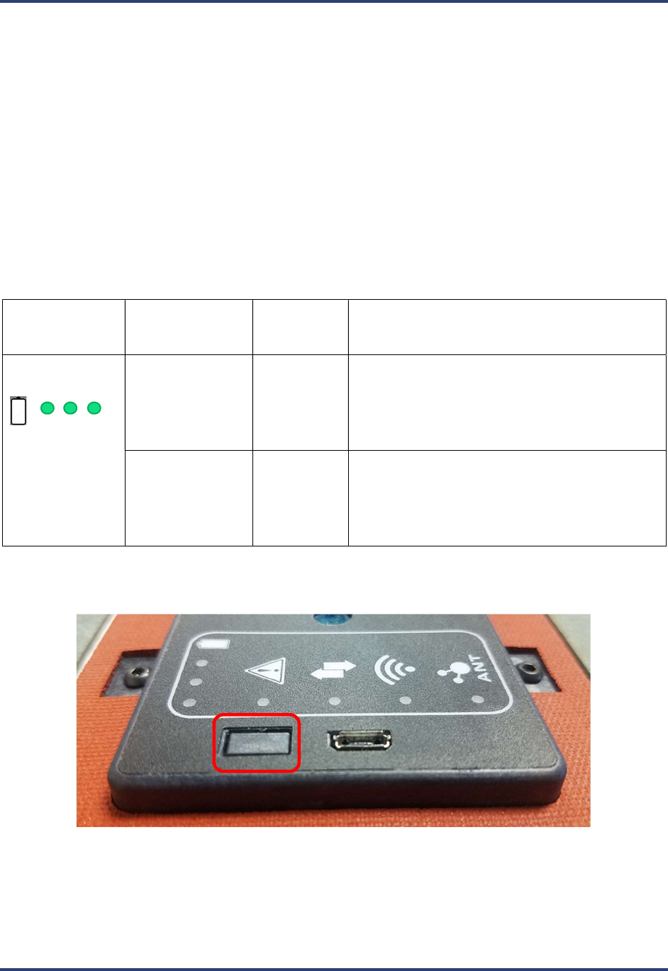
The Power Button
Push power button momentarily to turn on or off
Hold power button for 10 seconds for a hard reset of the hardware
SRA Smart Reflow Analyzer Hardware Guide SRA-330200-000
8
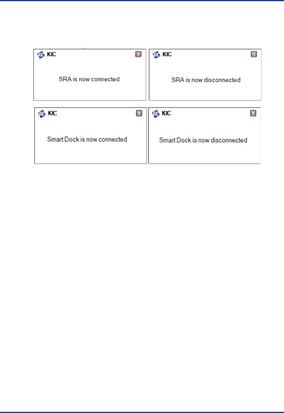
Set Up the SRA
Once the Profiling Software 2G is installed and running, whenever you connect an SRA Smart Reflow Analyzer to a
USB port, a message appears in the lower right of the screen reporting that it is detected. When you unplug the device,
another message appears showing it has been disconnected from the PC. This is true for the Smart Dock as well. It is
a momentary message which disappears automatically after a few seconds:
SRA Smart Reflow Analyzer Hardware Guide SRA-330200-000
9
Choosing the Mode of Profiling
There are two modes – Datalog or Transmitter. In Datalog mode, the device records data as it moves through the
thermal process that it later will transfer to the computer through a USB cable. In Transmitter mode, the device sends
the data live, via Wi-Fi connection with the Smart Dock, and is displayed in the software wirelessly.
Datalog Mode
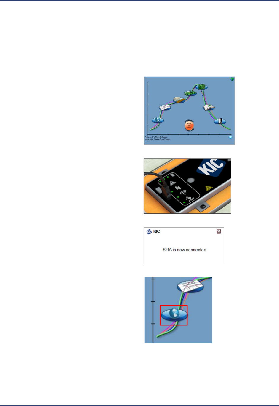
1. Launch Profiling Software 2G. Your Profiling
Software USB Security Dongle is required to use
all features in the software.
2. Use the communication cable to connect the SRA
to a USB port on the computer.
3. A message appears confirming the SRA is
detected.
4. From the Main screen, click on the Globe button
to display the Global Preferences screen.
SRA Smart Reflow Analyzer Hardware Guide SRA-330200-000
10
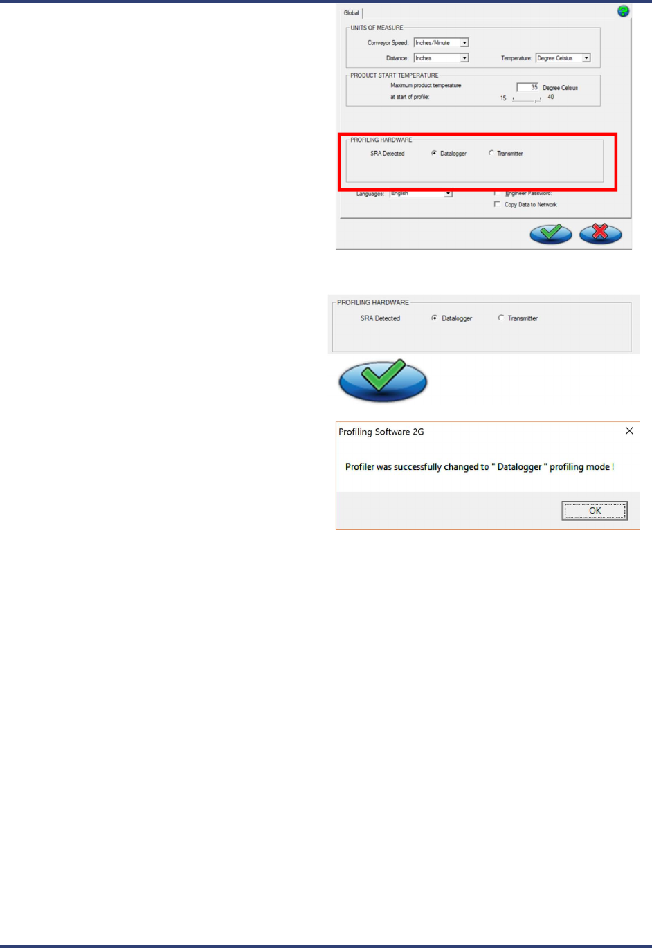
5. The software shows the SRA as detected in the
Profiling Hardware panel and displays radio button
choices for specifying the communication mode.
6. Click the radio button for Datalogger, followed by
the Save (green check) button:
7. Click OK on the message boxes (no messages
appear if the Datalogger radio button was already
selected).
You are returned to the Main screen.
SRA Smart Reflow Analyzer Hardware Guide SRA-330200-000
11
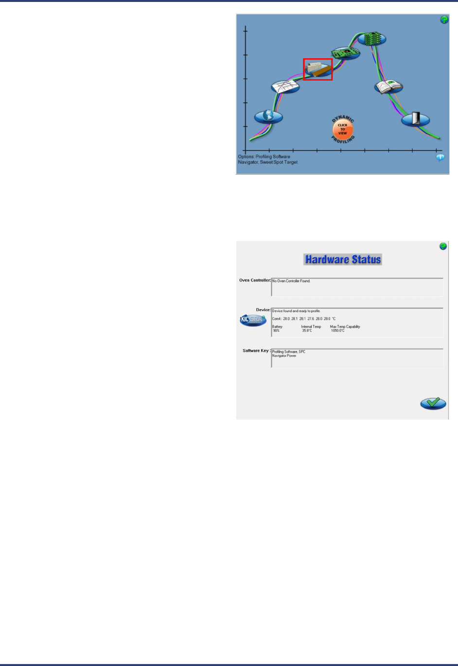
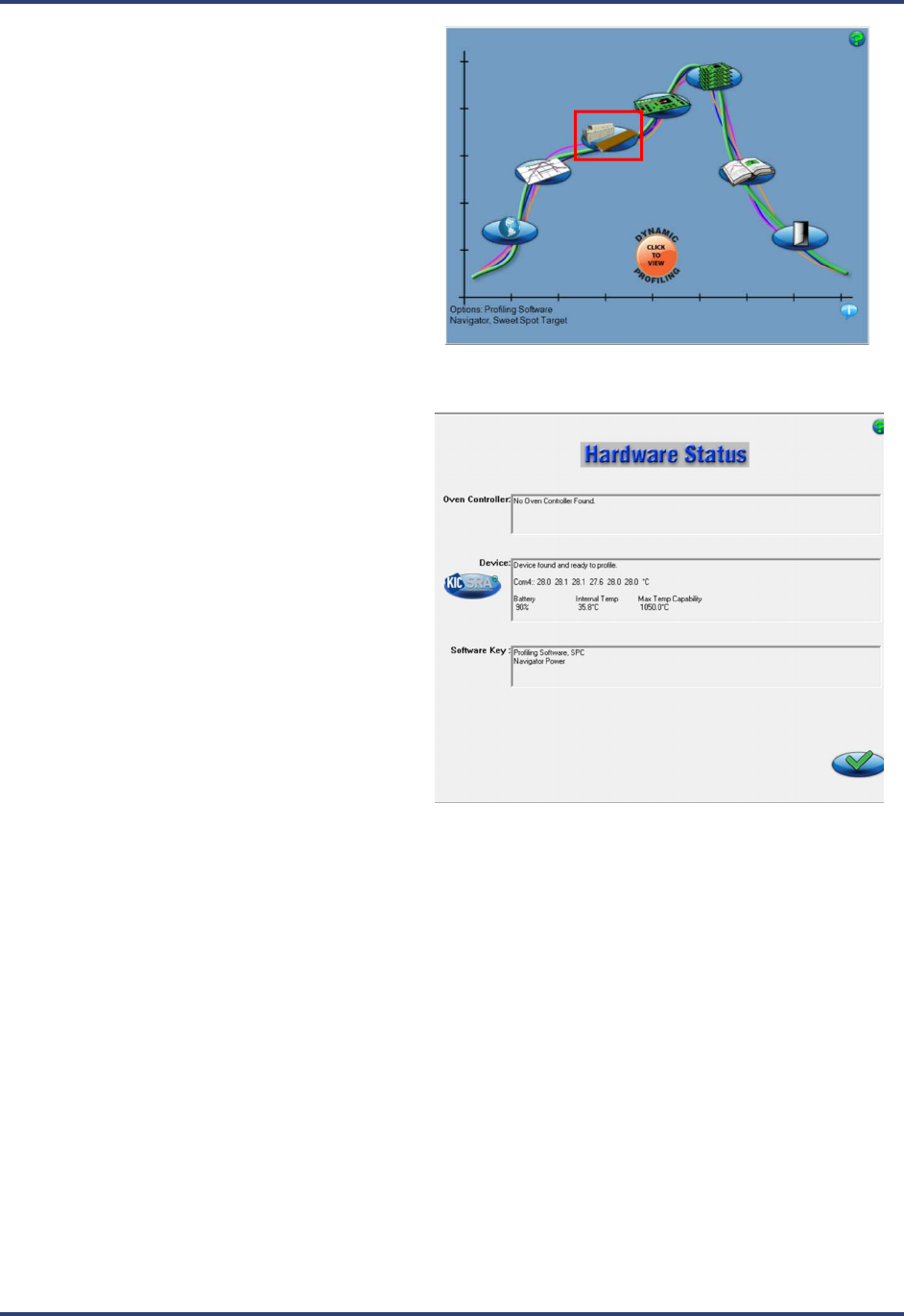
8. When the Main screen appears, click the
Hardware Status button.
9. The Hardware Status screen appears, showing the
status of the device, and confirming that the
software is connected to the SRA and receiving
live readings.
Note: The Device panel displays live temperature
values and the current battery voltage. TC
connections display the live temperature or appear
as open (opn) if there is no reading from that TC.
SRA Smart Reflow Analyzer Hardware Guide SRA-330200-000
12
Wireless Mode
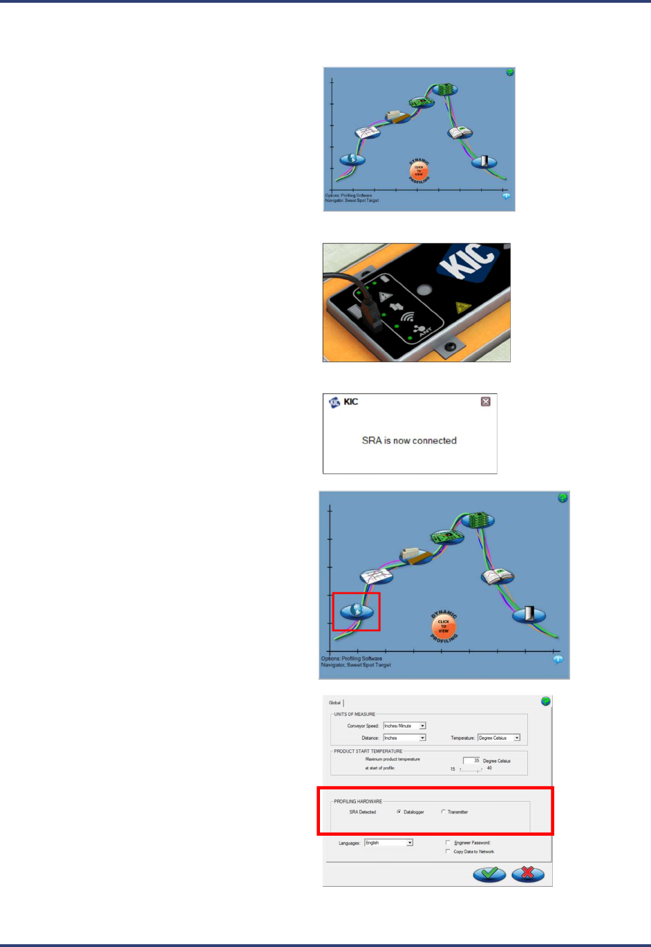
1. Launch Profiling Software 2G. Your Profiling
Software USB Security Dongle is required to
use all features in the software.
2. Use the communication cable to connect the
SRA to a USB port on the computer.
3. A message appears confirming the SRA is
detected.
4. From the Main screen, click on the Globe button
to display the Global Preferences screen.
5. The software shows the SRA as detected in the
Profiling Hardware panel and displays radio
button choices for specifying the communication
mode.
SRA Smart Reflow Analyzer Hardware Guide SRA-330200-000
13
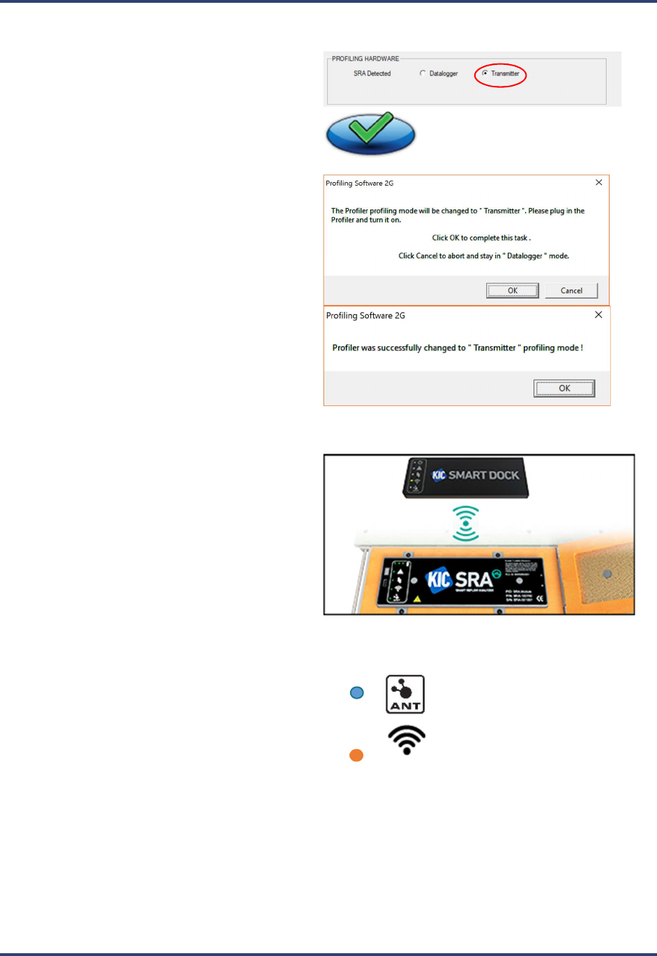
6. Click the radio button for Transmitter,
followed by the Save (green check) button
7. Click OK on the message boxes. You will then
be returned to the main screen.
8. Remove the USB cable from the SRA and insert
it into the Smart Dock.
9. Tap the Smart Dock and then cover either one of
the two (2) SRA speed sensor windows on top
of the SRA for at least 5 seconds to start the
pairing.
10. The ANT blue LED on both devices flashes
until the devices are paired.
11. The Wi-Fi orange LED on both devices flashes
every 3 seconds indicating a successful Wi-Fi
connection.
SRA Smart Reflow Analyzer Hardware Guide SRA-330200-000
14
12. When the Main screen appears, click the
Hardware Status button.
13. The Hardware Status screen appears, showing
the status of the device, and confirming that the
software is receiving the live Wi-Fi signal from
the SRA.
Note: The Device panel displays live
temperature values and the current battery
voltage. TC connections display the live
temperature or appear as open (opn) if there is
no reading from that TC.
SRA Smart Reflow Analyzer Hardware Guide SRA-330200-000
15
Hardware Status: LED Status Window
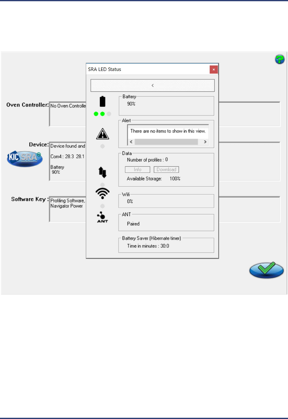
With the SRA connect you can access an LED Status Window from the Hardware Status screen by clicking on the
blue logo to the left of the Device panel. This pop up window will indicate the matching status of the SRA LEDs on
the SRA hardware, along with brief status descriptions. This will allow you to identify the state or mode of the
device based on the LED display.
Battery indicates percent of battery charge.
Alert (if LED is on) will list any and all alerts in the list box.
Data LED status will indicate the number of profiles currently stored in the SRA with access for information on the
stored profiles and the ability to download them. It also displays the amount of available storage (as a percentage).
Wi-Fi indicates the signal strength of the Wi-Fi connection to the Smart Dock (displayed as a percentage).
ANT will list if the SRA is paired with a Smart Dock or not.
Battery Saver indicates the time in minutes the SRA will turn off automatically if left idle.
SRA Smart Reflow Analyzer Hardware Guide SRA-330200-000
16
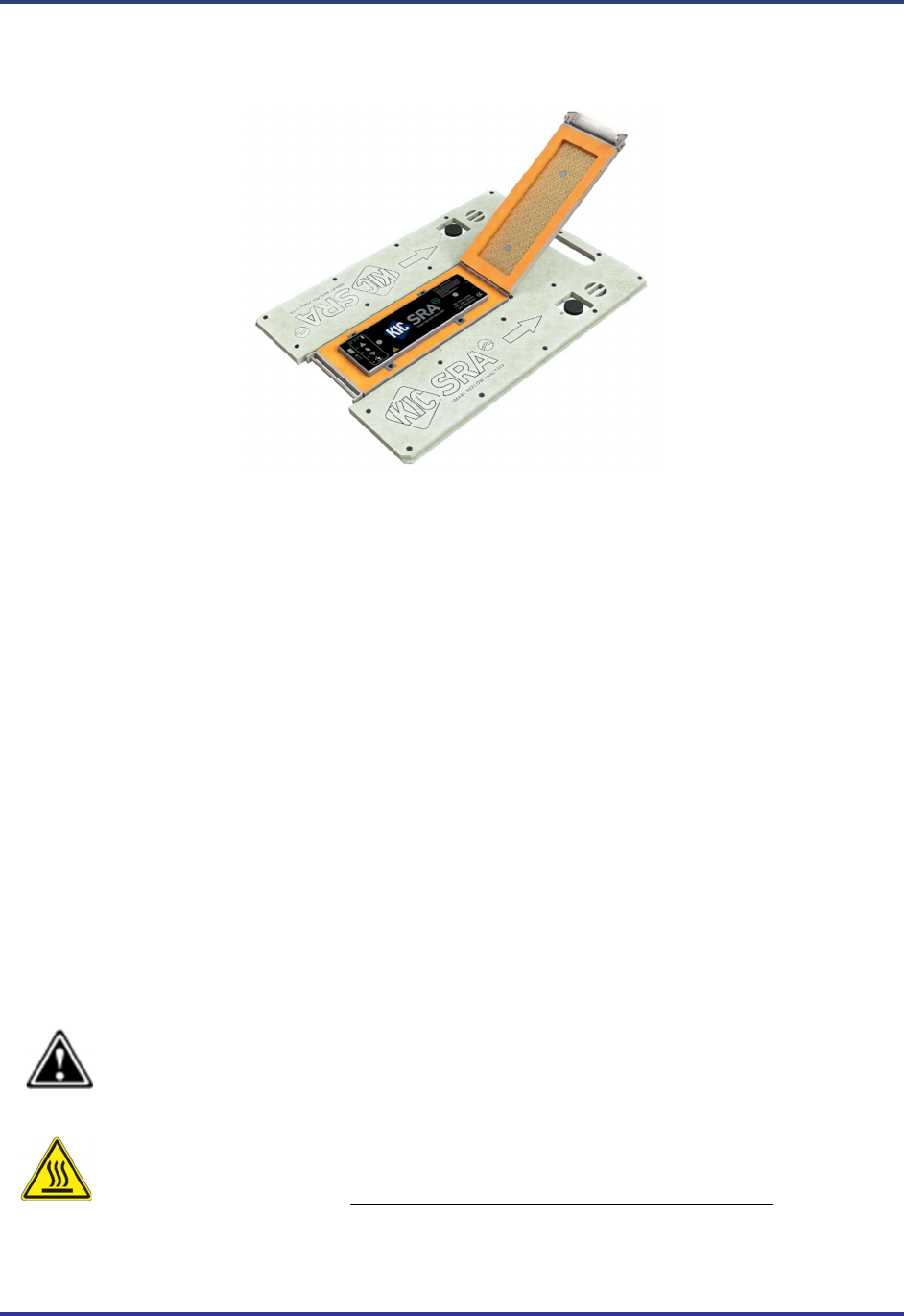
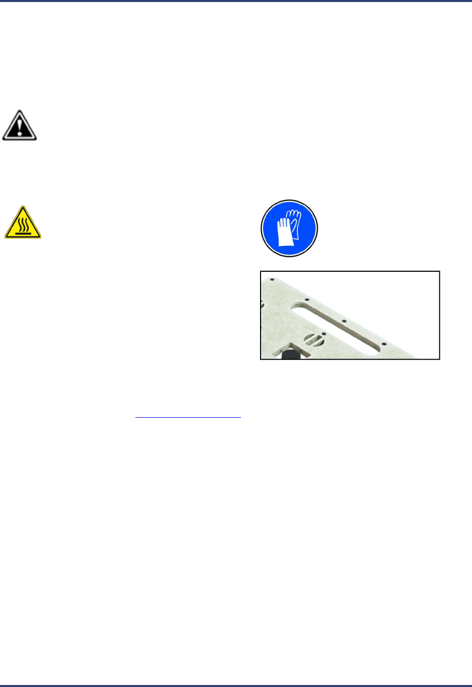
Thermal Protection
The SRA Smart Reflow Analyzer includes a built-in thermal shield—a stainless steel enclosure that protects the
internal electronics (SRA module) against extreme heat during runs through a thermal process.
Caution: The SRA module’s maximum internal temperature is 85
C.
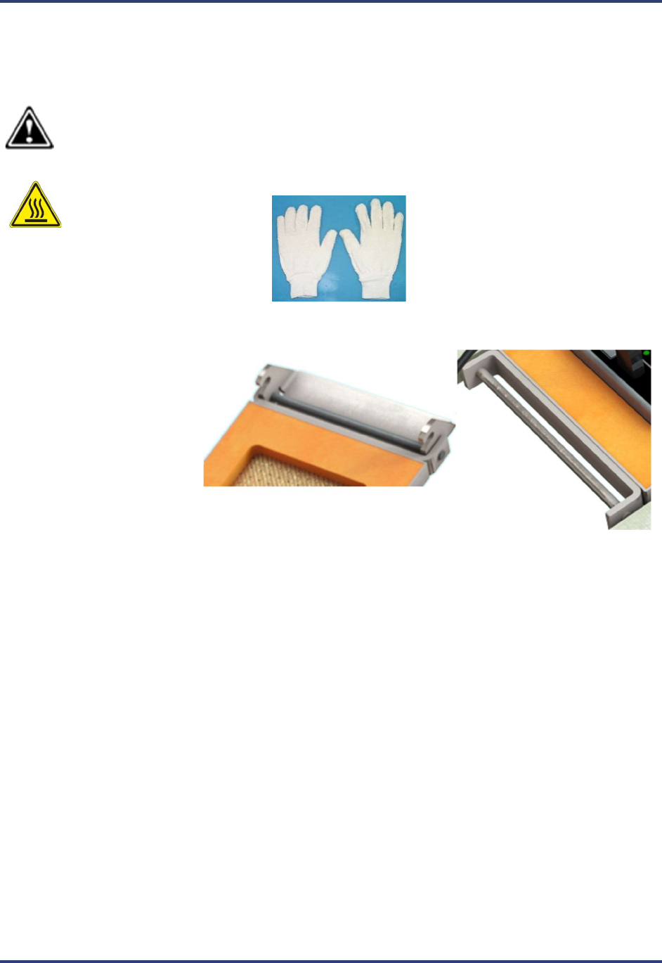
Note: Gloves are required
when the device has just
emerged from the oven. Your
SRA kit includes a pair of specially
selected safety gloves.
1. The top side of the shield
has a latching tab which
hooks on to the bottom
section of the shield.
2. Close the lid of the shield and rotate the latch downward to lock it in place.
SRA Smart Reflow Analyzer Hardware Guide SRA-330200-000
17
Safe Handling after Exiting the Oven
As the SRA emerges from the oven, the pallet and shield will be hot to the touch. Your kit includes a pair of safety
gloves, and it is absolutely required that you use these gloves for handling the unit after an oven run.
The safety gloves provided with your kit feature a fabric construction that is rated to permit holding an object heated
to 120°C (250°F) for up to 30 seconds. Operators should never hold the device longer than 30 seconds and should
only hold it as long as needed to move it safely to a workbench or other appropriate flat surface.
Caution: Never substitute gloves that are not rated for similar temperature and holding cycle specifications.
Contact your device manufacturer for replacement or extra pairs.
Safely Remove the SRA from the Oven
Hot Surface: Wear the safety gloves supplied
with your kit during this procedure.
1. As the SRA reaches the end of the conveyor, the
handle at the front of the device can be used to lift it
from the conveyor.
2. Carry the SRA away from the oven area, and place on a flat, level surface that is unaffected by the unit’s
heat.
3. Follow the procedure titled Safely Opening the Shield.
SRA Smart Reflow Analyzer Hardware Guide SRA-330200-000
18
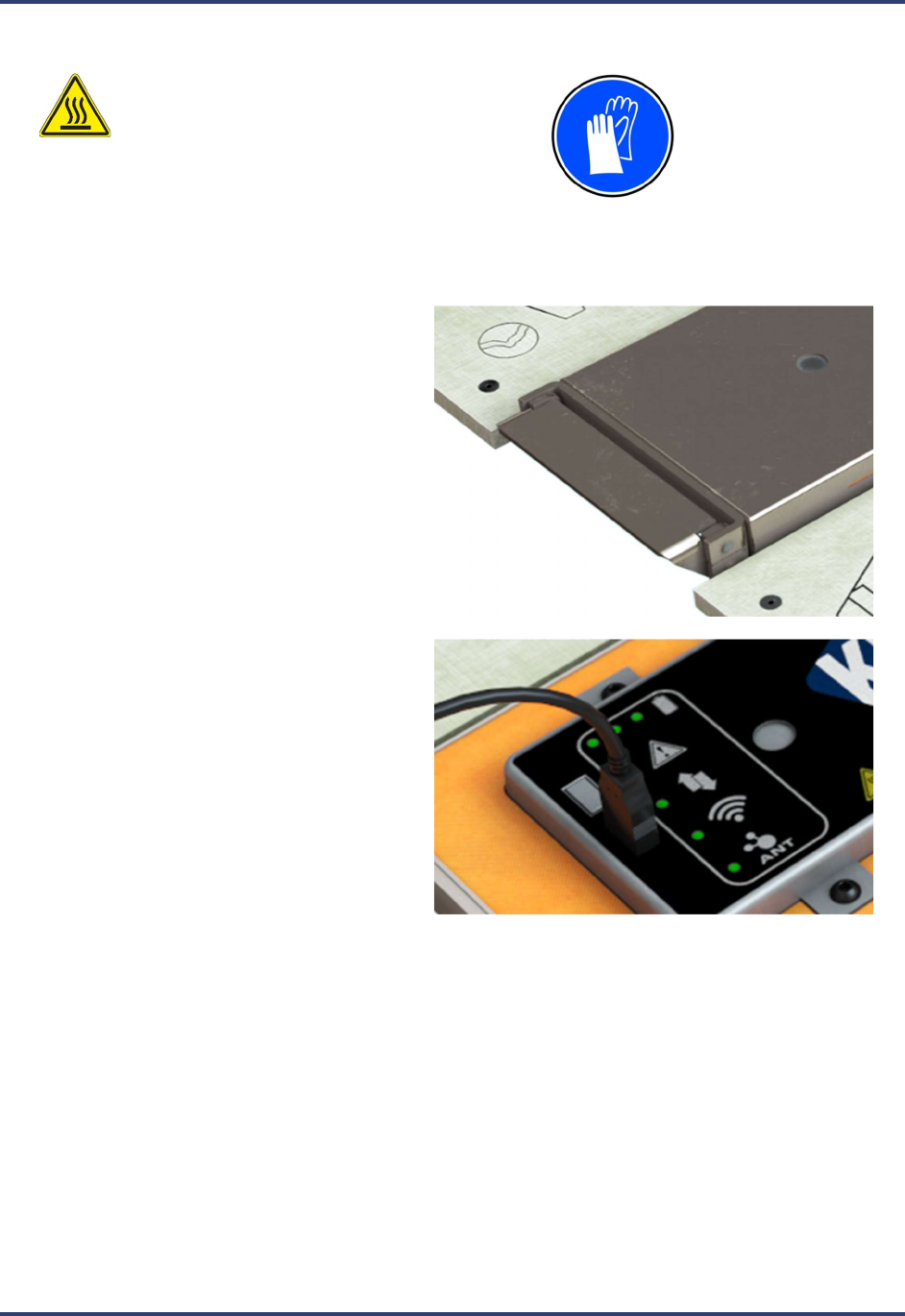
Safely Opening the Shield
Hot Surface: Wear the safety gloves
supplied with your kit during this
procedure.
1. Carefully pull up on the latch to open the
shield.
2. With a datalogger model, connect the USB
download cable to the SRA module to
download the data.
Note: On Wi-Fi enabled versions, it is not
necessary to connect the USB cable to the
SRA module as the data is wirelessly
downloaded via the Smart Dock.
3. It is recommended to place the SRA in front of a fan or other cooling station arrangement to aid in the cooling
process.
SRA Smart Reflow Analyzer Hardware Guide SRA-330200-000
19
Specifications and normal environmental conditions
Accuracy: ±0.5°C
Resolution: ±0.1°C
Internal Operating Temp: 0°C to 85°C
Humidity Range: 20-85% non-condensing
Measurement Range: -150°C to 1050°C
Sample Rate: Up to 50 readings per second
Data Points: 72000 per channel
PC Connection: USB 2.0 (Std-A/Micro-B)
Power:
NiMH battery: 2.4Vdc
USB connection to PC:
5Vdc, 500mA
Wireless Communication: Wi-Fi 2.4 GHz & ANT 2.4 GHz
Embedded Thermocouples: Type K
Dimensions (L x W x H mm): 432.0 x 305.0 x 23.0
For Indoor Use Only
Overvoltage Category 1
Max constant voltage handled: 3.15v
Max transient voltage handled: 60v for less than 1ms
Cleaning Procedure
Clean the exterior surfaces of the chassis with a dry lint-free cloth. If any dirt remains, use a cloth or swab dipped in
a 75% isopropyl alcohol solution. Use a swab to clean narrow spaces around the button and connector. Do not use
abrasive compounds on any part of the chassis, as they may damage it.
Be sure to keep the speed sensor windows on both the SRA module and thermal shield cover clean of dust and debris
to ensure proper operation.
Avoid the use of chemical cleaning agents, which might damage the plastics used in this instrument. Use a 75%
isopropyl alcohol solution as a cleaner and wipe with a clean cloth dampened with deionized water. Before using
any other type of cleaner, consult your KIC representative.

SRA Smart Reflow Analyzer Hardware Guide SRA-330200-000
20
Regulatory Compliance
FCC
This device complies with part 15 of the FCC Rules. Operation is subject to the following two conditions:
(1) This device may not cause harmful interference, and (2) this device must accept any interference
received, including interference that may cause undesired operation.
FCC Caution: Changes or modifications not expressly approved by the party responsible for compliance
could void the user's authority to operate this equipment.
NOTE: This equipment has been tested and found to comply with the limits for a Class A digital device,
pursuant to part 15 of the FCC Rules. These limits are designed to provide reasonable protection against
harmful interference when the equipment is operated in a commercial environment. This equipment
generates, uses, and can radiate radio frequency energy and, if not installed and used in accordance with
the instruction manual, may cause harmful interference to radio communications. Operation of this
equipment in a residential area is likely to cause harmful interference in which case the user will be
required to correct the interference at his own expense
RF Exposure statement: To comply with FCC RF exposure requirements, a separation distance of at least 20cm
must be maintained between the SRA Smart Flow Analyzer and all persons when WiFi data is being transmitted.
SRA Smart Reflow Analyzer Hardware Guide SRA-330200-000
21
Calibrating the SRA
To keep your device operating at proper factory specifications, KIC recommends calibrating the unit every 12
months. The procedure detailed below lets you calibrate the device to within +1.1°C (+1.9°F).
The calibration procedure follows a sequence of multiple steps:
1. Removal of SRA module from main assembly
2. Establishing SRA module hardware/software communication
3. Setting/Adjusting the Cold Junction Reference (CJREF) offset value
4. Setting/Adjusting the Gain value
5. Reinstallation of SRA module into main assembly
The CJREF offset is the amount of temperature to add or subtract from the base profiler readings. KIC recommends
setting this value to the same temperature as the CJREF (Internal) temperature. You can view the CJREF (Internal)
temperature by clicking the Get Current TC button on the Calibration Log screen displayed during the procedure.
The Gain Adjust portion of the calibration procedure affects the accuracy of the profiler across its temperature
capability range. For maximum accuracy, set the Gain Adjust calibration value to the highest temperature you
expect to read for your thermal process.
Note: The maximum temperature setting is the highest temperature that the SRA is set to read. The highest
temperature that the device is capable of reading is 1050C (1922F). This device is factory preset at 1050C
(1922F), but you can change the setting to suit your needs.
Note: Only qualified persons should perform the calibration procedure. If you need assistance, training, or need to
arrange for KIC to calibrate your SRA Smart Reflow Analyzer contact KIC Technical Support tech@kicmail.com,
asia.tech@kicmail.com, europe.tech@kicmail.com.
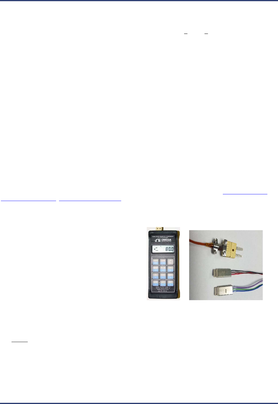
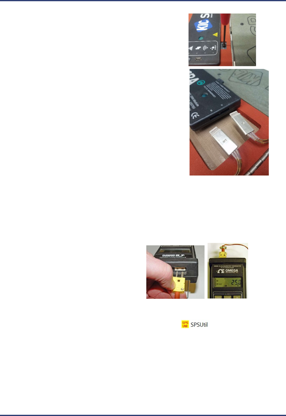
Before starting the procedure
Assemble the following hardware:
o SRA module
o Micro USB communication cable
o Type K thermocouple simulator
o Calibration Adapter* (SRA version)
*Contact KIC to acquire the correct
calibration adapter cable.
sales@kicmail.com
TC Simulator SRA Calibration Adapter
Be prepared to run the Profiling Software 2G application and/or the SRA Hardware Utility.
Do not attempt to calibrate the SRA module with an ungrounded computer as this may produce inaccurate
resuls/
SRA Smart Reflow Analyzer Hardware Guide SRA-330200-000
22
Remove SRA Module
1. Open the thermal shield cover, locate and remove the four (4) M3
mounting screws.
2. Lift the SRA module slightly out of the shield and then unplug the
two (2) connectors at the front edge of the module. This allows
the module to be taken completely out of the main assembly.
Establish communication
3. Connect the SRA module to the computer USB port. (The device should power on automatically when
connected to the PC.)
4. Connect the calibration adapter cables to the SRA module, making sure to note the orientation of the
connector. The side of the connectors stamped with the word ‘Top’ should face up. Either connector can
plug into either slot of the SRA module.
5. Connect the other end of the adapter to the
output port (left side when instrument
viewed upright) of the type K thermocouple
simulator.
6. Turn on the power to the thermocouple simulator, and set the output value to 25°C (77°F).
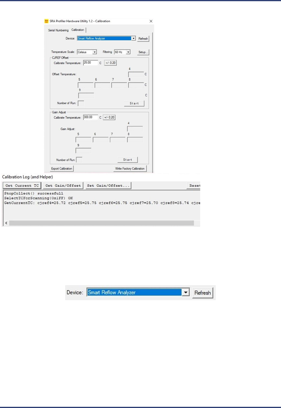
7. Open the SRA Utility folder and double click the SRA Util icon (default folder location =
C:\Profiling Software 2G\SPS Utility).
SRA Smart Reflow Analyzer Hardware Guide SRA-330200-000
23
8. The SRA Hardware Utility - Calibration screen and the Calibration
Log screens appear:
9. Ensure that Smart Reflow Analyzer is displayed in the Device field, the appropriate temperature scale is
selected, and the proper filtering for your location is selected.
Note: When the software utility is open and the hardware connected, if the SRA name does not appear in
the Device field, clicking the Refresh button forces the utility to search for the presence of the hardware
and display the name in the field if found:
10. On the Calibration Log (and Helper) window, click the Set Idle button, and then click the Get Current TC
button to verify communication between the software and the profiler. (If communicating properly the
current live temperature readings from the device appear as shown in example above.)
SRA Smart Reflow Analyzer Hardware Guide SRA-330200-000
24
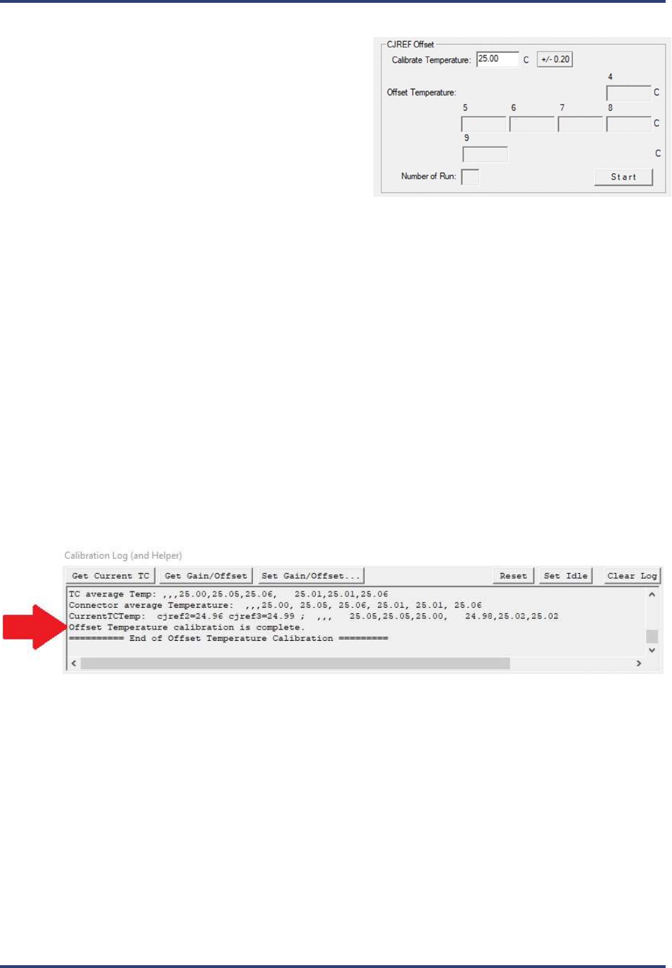
Specify the CJREF offset
1. Open the SRA Hardware Utility - Calibration
screen.
2. In the CJREF Offset panel’s Calibrate
Temperature field, accept the recommended
default temperature of 25°C (77°F) or type in a new
value between 10°C (50°F) and 500°C (932°F).
Note: The Calibrate Temperature value should be selected to represent an anticipated ambient temperature.
Calibrating to this temperature will likely yield acceptably accurate performance. The selected default (25°C)
approximates typical room temperature and is recommended for most lead-free soldering applications. However,
the number of ovens present or other site-environment factors might influence your selection of this value. You can
type in whatever value better matches your specific situation. If your thermal process is well established around
specific temperatures, it may make sense to focus calibration on these target values.
Note: Older versions of software may indicate other values as the default temperature.
3. Adjust the output on the thermocouple simulator to match your specified calibration temperature.
4. When the values match, click the-Start button to begin calibration.
The software automatically adjusts the calibration temperature for each of the device ports, typically
resulting in different values among the four ports. Electronic adjustments also tune the profiler for
maximum accuracy at the specified temperature.
When the software completes the offset calibration, a status messages appears in the Calibration Log area
at the bottom of the utility screen:
SRA Smart Reflow Analyzer Hardware Guide SRA-330200-000
25
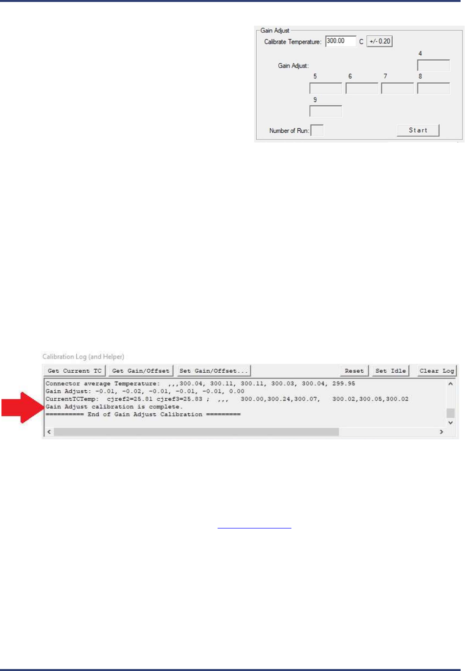
Specify the gain adjustment
1. Open the SRA Hardware Utility - Calibration
screen.
2. In the Gain Adjust panel’s Calibrate
Temperature field, accept the recommended
default temperature of 300°C (572°F) or type in a
new value between 10°C (50°F) and 500°C
(932°F).
Note: The recommended default temperature is selected for its suitability to typical lead-free soldering
applications. The range of values presented offers you the choice of calibrating to a maximum temperature
or to a specific temperature of interest. Calibrating to the maximum temperature will yield acceptably
accurate performance throughout the range. Alternatively, if your thermal process is well established
around specific temperatures, it may make sense to focus calibration on these target values.
Note: Older versions of KIC software may indicate other values as the default temperature.
3. Adjust the output on the thermocouple simulator to match your specified calibration temperature.
4. When the values match, click the-Start button to begin calibration.
The software automatically adjusts the Gain setting while electronic adjustments tune the profiler for
maximum accuracy at the specified temperature.
When the software completes the gain adjustment, a status messages appears in the Calibration Log area
at the bottom of the utility screen:
5. Close and exit the software to end the procedure.
Note: In the Gain Adjust panel, the Number of Run field displays a running count of the number of times
you needed to run the final gain adjustment part of the calibration procedure. The count can go to a
maximum of eight. While it is typical to restart the gain adjustment two or three times before achieving
final calibration, a run count number that exceeds five or six can indicate that the device has a problem that
should be analyzed by KIC technical support. tech@kicmail.com

SRA Smart Reflow Analyzer Hardware Guide SRA-330200-000
26
Reinstall SRA Module
1. Reinsert the two (2) connectors from the main assembly into the front of the SRA module. NOTE: Be sure
to take note of orientation of connectors – A to A, B to B.
2. Position the SRA module in place inside the main assembly
and reinstall the four (4) mounting screws.

SRA Smart Reflow Analyzer Hardware Guide SRA-330200-000
27
Contact KIC
On the Web
You can find the latest KIC product news along with a library of
useful information at our website:
www.kicthermal.com or www.kic.cn
KIC Technical Support
KIC Tech Support is available by email:
USA: tech@kicmail.com
Europe: europe.tech@kicmail.com
Asia: asia.tech@kicmail.com
KIC Service/Repair
All service and repair of the SPS Smart Profiler or Smart Dock, other than the calibration, requires contacting a KIC
Service center and having the service/repair conducted by personnel authorized by KIC.
KIC Product Training
Contact KIC Customer Support by email, training@kicmail.com
KIC Sales
Contact KIC sales:
USA: sales@kicmail.com
Europe: europe.sales@kicmail.com
Asia: asia.sales@kicmail.com
China: asia.sales@kicmail.com
Find the KIC Representative in Your Area
Send an email, or visit our web page to find a local representative.