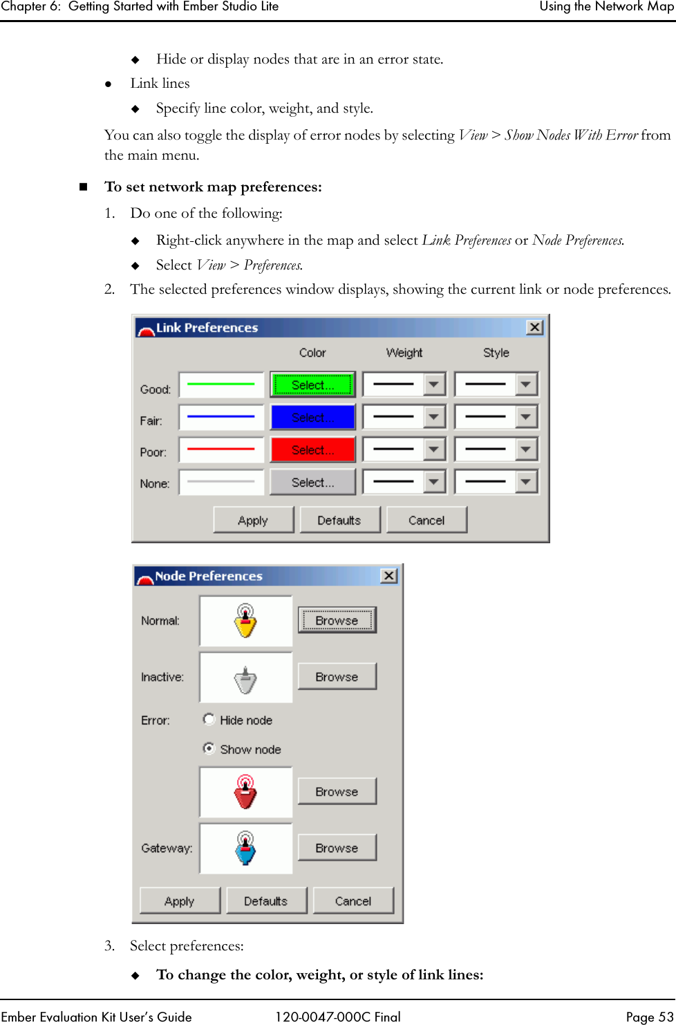
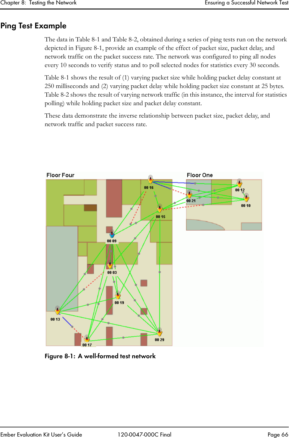
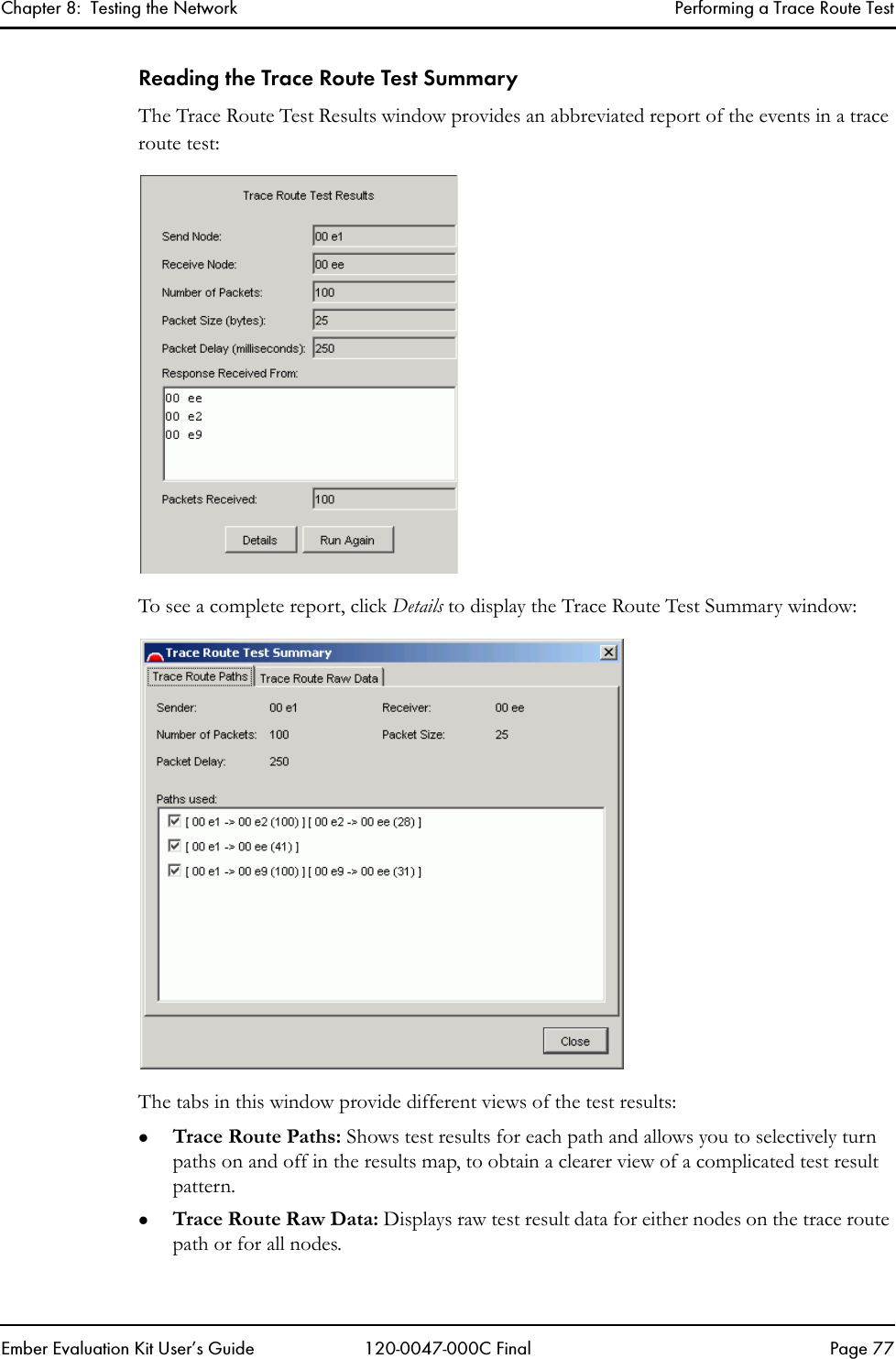
Ember EK1020CON Wireless Network Evaluation Kit User Manual EKUserGuide
Ember Corporation Wireless Network Evaluation Kit EKUserGuide
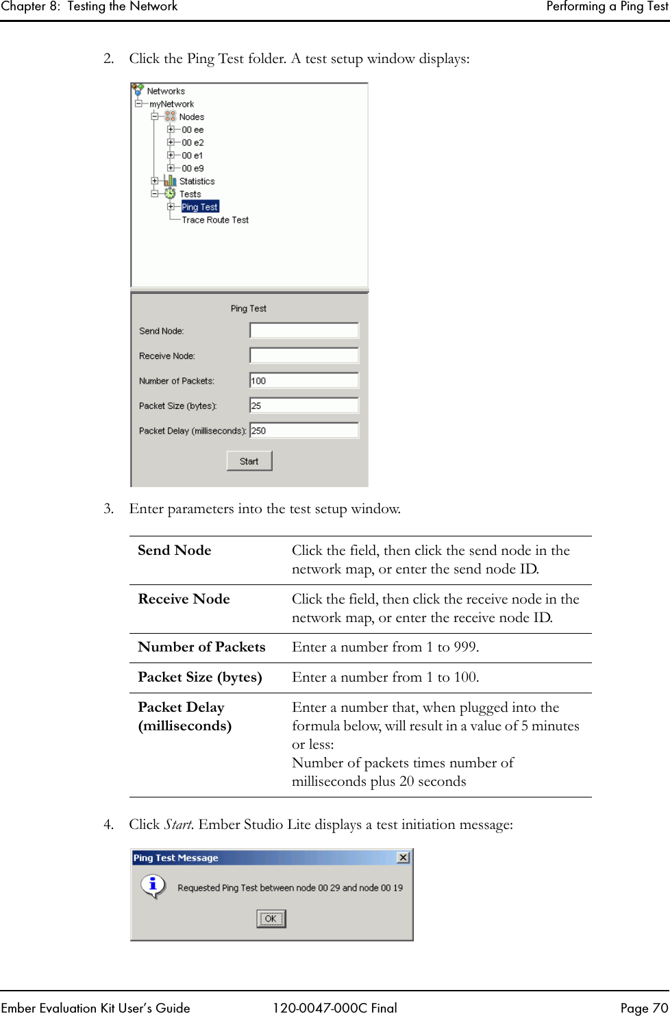
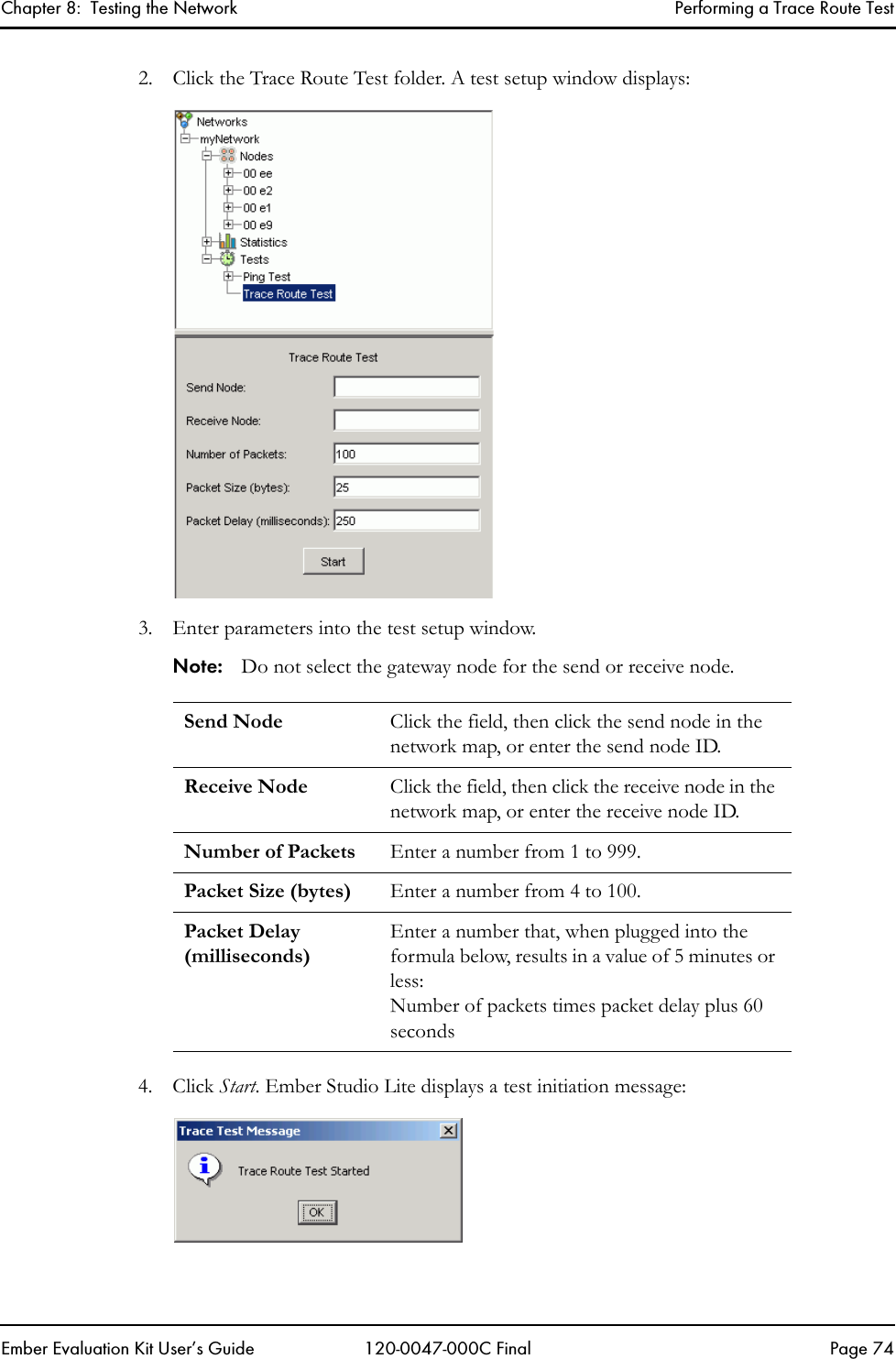
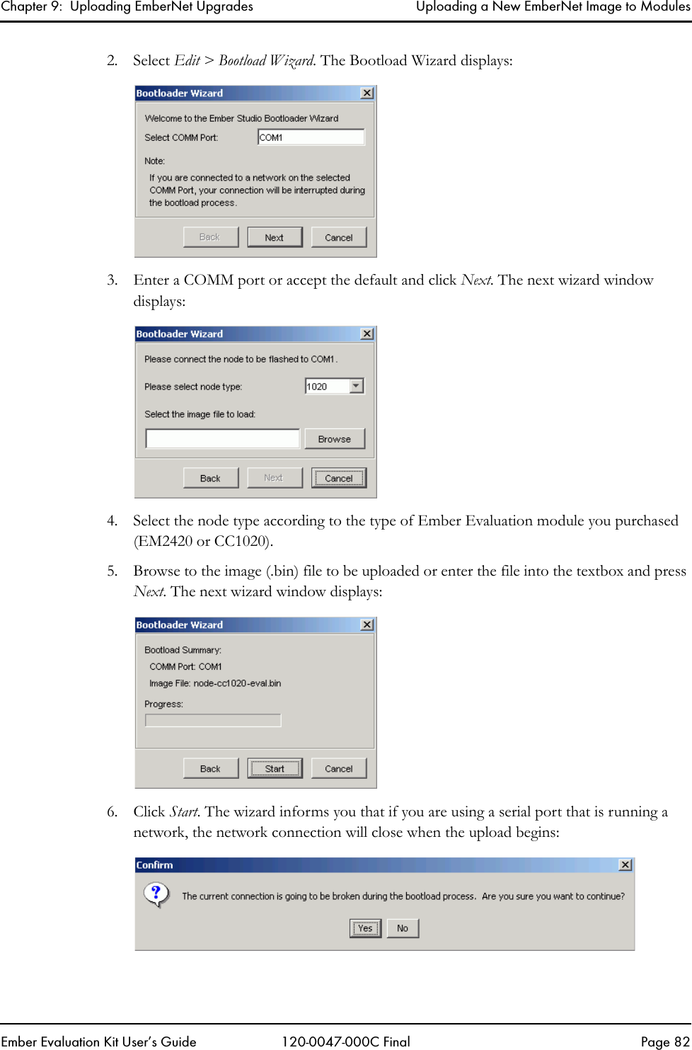
UserManual.wiki
>
Ember
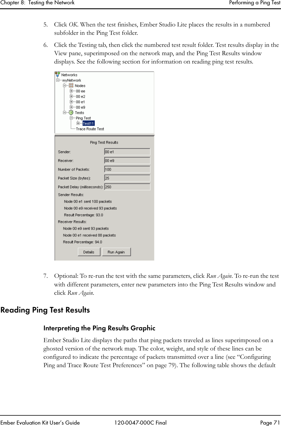
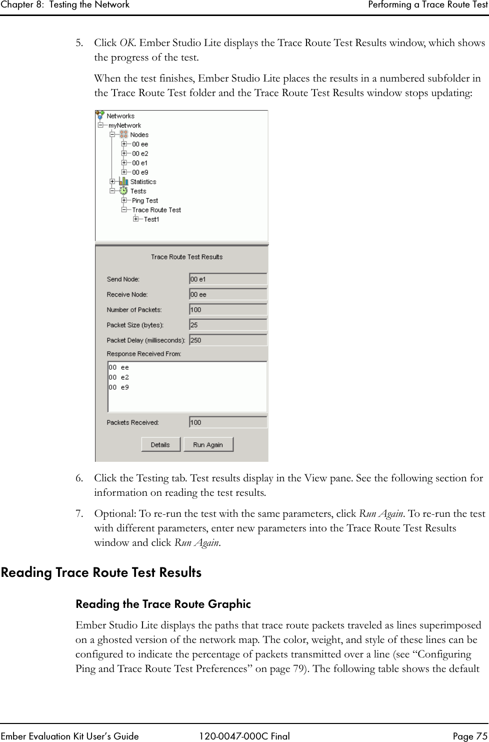
>
EK1020CON User Manual
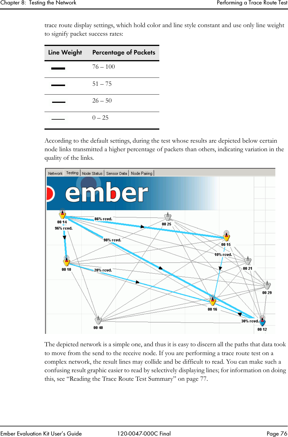
Revised Manual
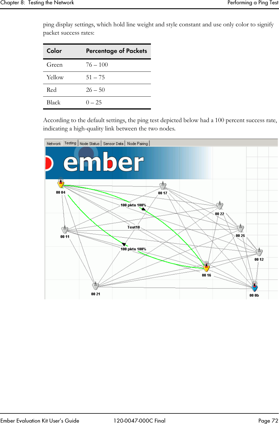
Navigation menu
Upload a User Manual
Namespaces
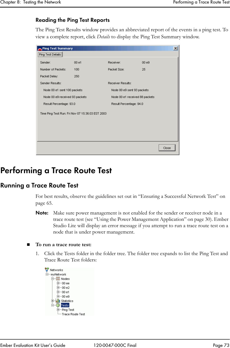
Wiki Guide
HTML
PDF
Info
Views
User Manual
Discussion / Help
Navigation


![Ember Evaluation Kit User’s Guide 120-0047-000C Final Page 8About This DocumentDocument Purpose . . . . . . . . . . . . . . . . . . . . . . . . . . . . . . . . . . . . . . . . . . . . . . . . . . . . 8Audience . . . . . . . . . . . . . . . . . . . . . . . . . . . . . . . . . . . . . . . . . . . . . . . . . . . . . . . . . . . 8Documentation Conventions . . . . . . . . . . . . . . . . . . . . . . . . . . . . . . . . . . . . . . . . . . . . 8Safety Symbols. . . . . . . . . . . . . . . . . . . . . . . . . . . . . . . . . . . . . . . . . . . . . . . . . . . . . . . 9Document PurposeThis document describes the contents and use of the Ember Evaluation Kit, including equipment and software installation, EmberNet™ network setup, use of Ember Studio Lite, and the debugging, building, and uploading of applications.AudienceThe audience for this document is customers who have purchased the Ember Evaluation Kit. Customers are assumed to understand basic networking concepts and to be familiar with networking hardware and software.Documentation ConventionsNotation Meaning ExampleItalics Identifies on-screen software menu options.Refresh ScreenUPPERCASE Identifies a keyboard key. ENTERRight-angle bracket Delimits a series of software program menu options to be clicked. Open > SaveCourier Identifies software code and, in body text, variables.void Main(String[] argv)the buffer variableAngle brackets around a termDelimits a placeholder to be replaced with the data indicated by the term.<ipAddress>](https://usermanual.wiki/Ember/EK1020CON/User-Guide-430060-Page-8.png)

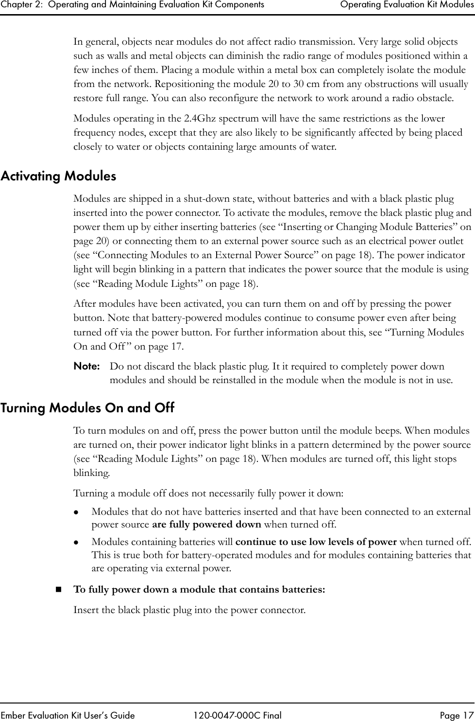

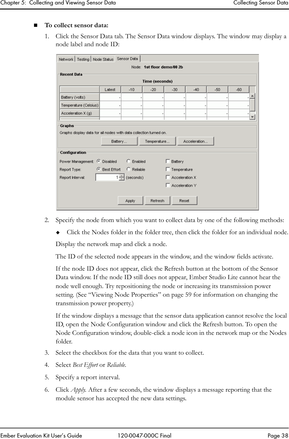
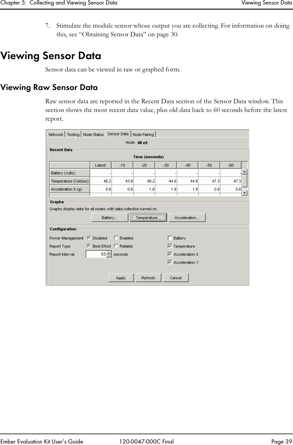
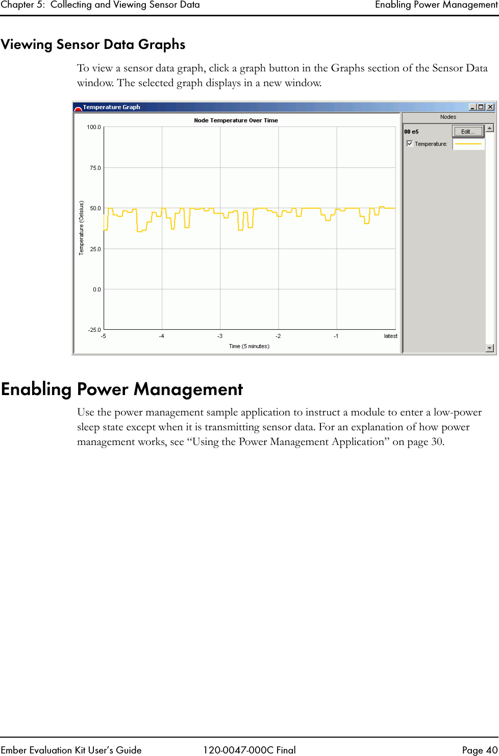
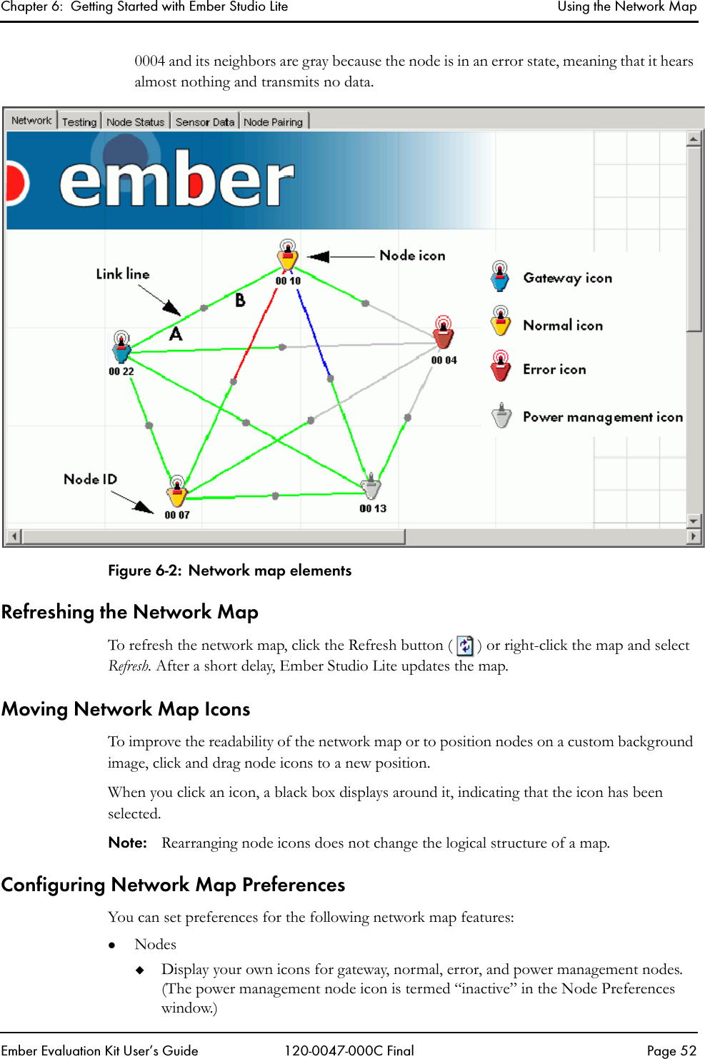
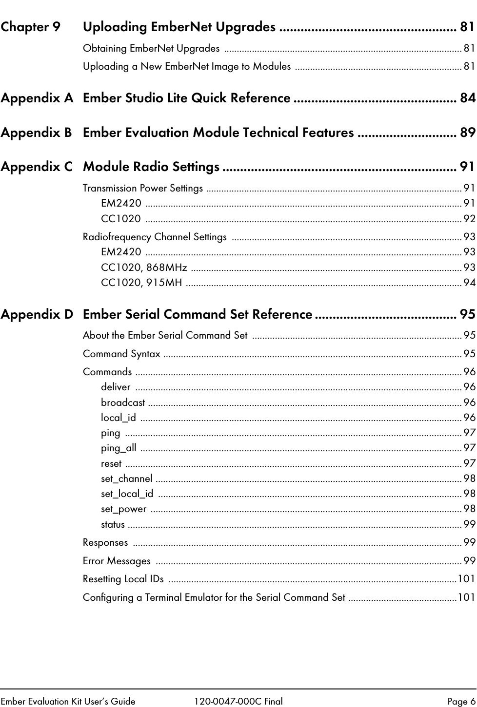
![Chapter 7: Managing Network Nodes Viewing Node PropertiesEmber Evaluation Kit User’s Guide 120-0047-000C Final Page 61ManufacturingString Five-part number assigned by the node manufacturer. The parts are defined below with reference to the following sample number:8473/0331/0060/01/A18473: Board number0331: Lot code (31st week of 2003)0006: Manufacturer’s serial number01: Manufacturing codeA1: Board revisionNodePair3 Either the EvalKitID for a node that has been paired to this node or “No Pair”NodePair2 Either the EvalKitID for a node that has been paired to this node or “No Pair”NodePair1 Either the EvalKitID for a node that has been paired to this node or “No Pair”Routing EnableRelay A flag that determines whether the node relays messagesRadio Transmission Power Transmission power, in dBBand Radio bandFrequencyChannel RF channelNeighborNumber of neighborsNumber of neighboring nodes[list of each neighbor node]Value representing the quality of a node’s link to each neighbor node. The range is 100 for the strongest possible link to 0 for no link.Table 7-1: Node Properties (Continued)CategoryProperty Definition](https://usermanual.wiki/Ember/EK1020CON/User-Guide-430060-Page-61.png)
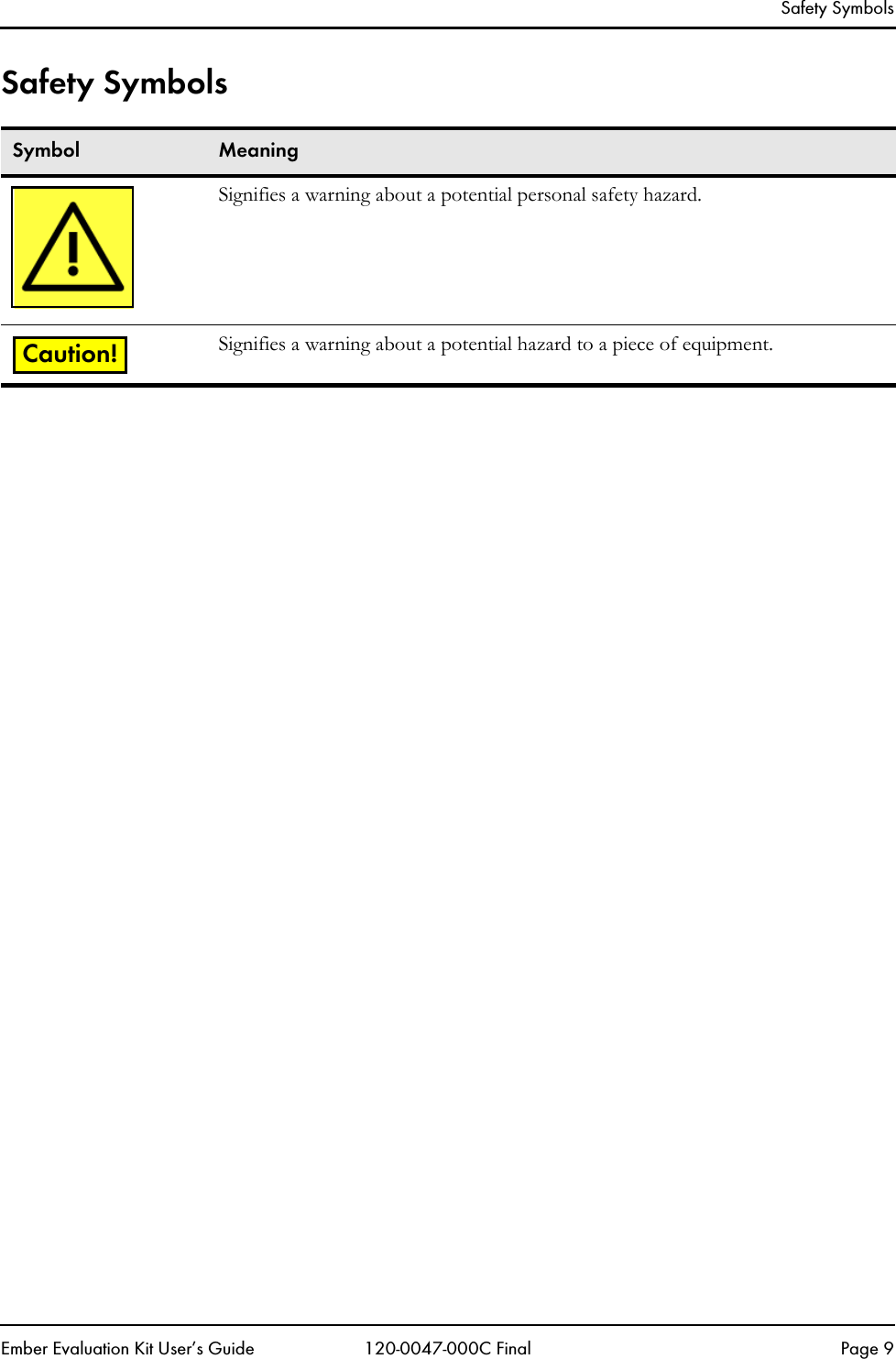
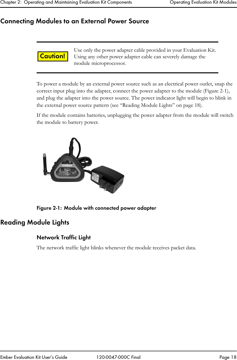
![Appendix D: Ember Serial Command Set Reference Error MessagesEmber Evaluation Kit User’s Guide 120-0047-000C Final Page 100Table D-2: Serial Command Set Error MessagesMessage Meaningerror 01 “serial port error” The serial port detected an error, such as a parity error (if enabled) or a garbled byte. If you receive this message, check cables.error 02 “command processor busy” Commands were sent too fast for the processor.error 03 “no such command” A command contained one or more of the following mistakes:zCommand was mistyped.Example: snedzOut-of-range value was specified.Example: set_power 4error 04 “incorrect command arguments”Illegal parameters were appended to a command.Example: broadcast 3 “hello all”error 05 “integer argument out of range”Out-of-range value was specified for command.Example: send 1000 “hello”, for a 5-node networkerror 06, “argument syntax error” Illegal value was specified for a numeric parameter.Examples: 2.2, Oerror 07, “message too long” String/binary parameter exceeded 80 characters or bytes. Example:send 3 “on and on and ...”error 08 “missing binary message terminator”Binary parameter to a command does not end with a closing square bracket (“]”).error 09, “broken connection” Gateway node could not reach the device specified in command. error 0A, “outgoing message pipeline full” NUM (where NUM is a device ID)Message queue for the specified node is full.](https://usermanual.wiki/Ember/EK1020CON/User-Guide-430060-Page-100.png)