Emc Fc4500 Users Manual Fibre Channel Storage Systems S FC4500, FC5300, And FC5700 CONFIGURATION PLANNING GUIDE
FC4500 to the manual 38366a40-31e9-473b-b269-21dddee98390
2015-02-06
: Emc Emc-Fc4500-Users-Manual-540044 emc-fc4500-users-manual-540044 emc pdf
Open the PDF directly: View PDF ![]() .
.
Page Count: 134 [warning: Documents this large are best viewed by clicking the View PDF Link!]
- EMC Fibre Channel Storage Systems Models FC4500, FC5300, and FC5700 CONFIGURATION PLANNING GUIDE
- Notice
- Contents
- Preface
- Chapter 1 - About Fibre Channel Storage Systems and Networks (SANs)
- Chapter 2 - RAID Types and Tradeoffs
- Chapter 3 - Planning File Systems and LUNs with Shared Switched Storage
- Chapter 4 - Planning LUNs and File Systems with Unshared Direct Storage
- Chapter 5 - Storage System Hardware
- Hardware for Shared Storage
- Hardware for Unshared Storage
- Planning Your Hardware Components
- Hardware Data Sheets
- Cabinets for Rackmount Enclosures
- Cable and Configuration Guidelines
- Hardware Planning Worksheets
- Hardware for Shared Storage
- Hardware Component Worksheet for Shared Storage
- Hardware Component Worksheet for Shared Storage
- Hardware for Unshared Storage
- Hardware Component Worksheet for Unshared Storage
- Hardware Component Worksheet for Unshared Storage
- Hardware Component Worksheet for Unshared Storage
- Hardware Component Worksheet for Unshared Storage
- Chapter 6 - Storage-System Management
- Index

EMC Enterprise Storage
EMC Corporation 171 South Street, Hopkinton, MA 01748-9103
Corporate Headquarters: (508) 435-1000, (800) 424-EMC2 Fax: (508) 435-5374 Service: (800) SVC-4EMC
EMC Fibre Channel Storage Systems
Models FC4500, FC5300, and FC5700
CONFIGURATION PLANNING GUIDE
P/N 014003039-02

EMC Fibre Channel Storage Systems Configuration Planning Guide
ii
Copyright © EMC Corporation 2000, 2001. All rights reserved.
Printed May 2001
No part of this publication may be reproduced or distributed in any form or by any means, or stored in a
database or retrieval system, without the prior written consent of EMC Corporation.
The information contained in this document is subject to change without notice. EMC Corporation assumes
no responsibility for any errors that may appear.
All computer software programs, including but not limited to microcode, described in this document are
furnished under a license, and may be used or copied only in accordance with the terms of such license.
EMC either owns or has the right to license the computer software programs described in this document.
EMC Corporation retains all rights, title and interest in the computer software programs.
EMC Corporation makes no warranties, expressed or implied, by operation of law or otherwise, relating to
this document, the products or the computer software programs described herein. EMC CORPORATION
DISCLAIMS ALL IMPLIED WARRANTIES OF MERCHANTIBILITY AND FITNESS FOR A PARTICULAR
PURPOSE. In no event shall EMC Corporation be liable for (a) incidental, indirect, special, or consequential
damages or (b) any damages whatsoever resulting from the loss of use, data or profits, arising out of this
document, even if advised of the possibility of such damages.
Trademark Information
EMC2, EMC, MOSAIC:2000, Symmetrix, CLARiiON, and Navisphere are registered trademarks and EMC Enterprise Storage, The Enterprise Storage
Company, The EMC Effect, Connectrix, EDM, SDMS, SRDF, Timefinder, PowerPath, InfoMover, FarPoint, EMC Enterprise Storage Network, EMC
Enterprise Storage Specialist, EMC Storage Logix, Universal Data Tone, E-Infostructure, Celerra, Access Logix, MirrorView, and SnapView are
trademarks of EMC Corporation.
All other trademarks mentioned herein are the property of their respective owners.

EMC Fibre Channel Storage Systems Configuration Planning Guide
iii
Preface..............................................................................................................................xi
Chapter 1 About Fibre Channel Storage Systems and Networks
(SANs)
Introducing EMC Fibre Channel Storage Systems.......................1-2
Fibre Channel Background..............................................................1-3
Fibre Channel Storage Components ..............................................1-4
Server Component (Host-Bus Adapter Driver Package with
Software).....................................................................................1-4
Interconnect Components ........................................................1-4
Storage Component (Storage Systems, Storage Processors
(SPs), and Other Hardware).....................................................1-9
Types of Storage System Installations..........................................1-10
About Switched Shared Storage and SANs (Storage Area
Networks) ........................................................................................1-11
Storage Groups.........................................................................1-12
Storage System Hardware for Shared Storage ....................1-15
About Unshared Storage ...............................................................1-16
Storage System Hardware for Unshared Storage ...............1-16
Chapter 2 RAID Types and Tradeoffs
Introducing RAID.............................................................................2-2
Disk Striping...............................................................................2-2
Mirroring.....................................................................................2-2
RAID Groups and LUNs ..........................................................2-3
RAID Types........................................................................................2-4
RAID 5 Group (Individual Access Array) .............................2-4
RAID 3 Group (Parallel Access Array)...................................2-5
Contents

EMC Fibre Channel Storage Systems Configuration Planning Guide
iv
Contents
RAID 1 Mirrored Pair ...............................................................2-7
RAID 0 Group (Nonredundant Array) ..................................2-8
RAID 1/0 Group (Mirrored RAID 0 Group).........................2-8
Individual Disk Unit .................................................................2-9
Hot Spare ....................................................................................2-9
RAID Benefits and Tradeoffs.........................................................2-12
Performance .............................................................................2-13
Storage Flexibility....................................................................2-14
Data Availability and Disk Space Usage..............................2-14
Guidelines for RAID Types ...........................................................2-17
Sample Applications for RAID Types..........................................2-19
Chapter 3 Planning File Systems and LUNs with Shared Switched
Storage
Dual Paths to LUNs..........................................................................3-2
Sample Shared Switched Installation ............................................3-3
Planning Applications, LUNs, and Storage Groups....................3-6
Application and LUN Planning ..............................................3-6
Application and LUN Planning Worksheet ..........................3-7
LUN and Storage Group Planning Worksheet .....................3-8
LUN Details Worksheet..........................................................3-11
Chapter 4 Planning LUNs and File Systems with Unshared Direct
Storage
Dual SPs and Paths to LUNs...........................................................4-2
Unshared Direct and Shared-or-Clustered Direct Storage .........4-2
Sample Unshared Direct Installation......................................4-2
Sample Shared-or-Clustered Direct Installation...................4-3
Planning Applications and LUNs..................................................4-4
Application and LUN Planning ..............................................4-4
Application and LUN Planning Worksheet ..........................4-5
LUN Planning Worksheet........................................................4-6
Completing the LUN Details Worksheet.............................4-12
Chapter 5 Storage System Hardware
Hardware for Shared Storage .........................................................5-3
Storage Hardware — Rackmount DPE-Based Storage
Systems .......................................................................................5-3
Disks............................................................................................5-4
Storage Processor (SP) ..............................................................5-5

v
EMC Fibre Channel Storage Systems Configuration Planning Guide
Contents
Hardware for Unshared Storage.................................................... 5-6
Types of Storage System for Unshared Storage ................... 5-6
Disks............................................................................................ 5-8
Storage Processor (SP).............................................................. 5-9
Planning Your Hardware Components ...................................... 5-11
Configuration Tradeoffs - Shared Storage .......................... 5-11
Configuration Tradeoffs - Unshared Storage ..................... 5-12
Hardware Data Sheets................................................................... 5-14
DPE Data Sheet........................................................................ 5-14
iDAE Data Sheet...................................................................... 5-16
DAE Data Sheet....................................................................... 5-18
Cabinets for Rackmount Enclosures............................................ 5-20
Cable and Configuration Guidelines .......................................... 5-21
Hardware Planning Worksheets .................................................. 5-24
Hardware for Shared Storage ............................................... 5-24
Hardware Component Worksheet for Shared Storage...... 5-25
Hardware Component Worksheet for Shared Storage...... 5-27
Hardware for Unshared Storage .......................................... 5-27
Hardware Component Worksheet for Unshared Storage. 5-30
Hardware Component Worksheet for Unshared Storage. 5-31
Hardware Component Worksheet for Unshared Storage. 5-33
Hardware Component Worksheet for Unshared Storage. 5-35
Chapter 6 Storage-System Management
Using Navisphere Manager Software ........................................... 6-3
Storage Management Worksheets.................................................. 6-5
Index ................................................................................................................................i-1


EMC Fibre Channel Storage-System Configuration Planning Guide
vii
1-1 Storage System Models ................................................................................ 1-2
1-2 Nodes - Initiator and Target ....................................................................... 1-3
1-3 Switch and Hub Topologies Compared .................................................... 1-6
1-4 A Switch Zone ............................................................................................... 1-7
1-5 16-Port Switch, Back View .......................................................................... 1-7
1-6 Nine-Port Hub .............................................................................................. 1-8
1-7 Disk-Array Processor Enclosure (DPE) ..................................................... 1-9
1-8 Types of Storage System Installation ....................................................... 1-10
1-9 Components of a SAN ............................................................................... 1-11
1-10 Sample SAN Configuration ...................................................................... 1-13
1-11 Data and Configuration Access Control with Shared Storage ............ 1-14
1-12 Storage System with a DPE and Three DAEs ........................................ 1-15
1-13 Storage System Hardware for Unshared Storage .................................. 1-17
2-1 Multiple LUNs in a RAID Group ............................................................... 2-3
2-2 RAID 5 Group ............................................................................................... 2-5
2-3 RAID 3 Group ............................................................................................... 2-6
2-4 RAID 1 Mirrored Pair .................................................................................. 2-7
2-5 RAID 1/0 Group (Mirrored RAID 0 Group) ............................................ 2-9
2-6 How a Hot Spare Works ............................................................................ 2-11
2-7 Disk Space Usage in the RAID Configurations ...................................... 2-16
3-1 Sample Shared Switched High Availability installation ........................ 3-3
4-1 Unshared Direct Installation ....................................................................... 4-2
4-2 Sample Clustered Installation ..................................................................... 4-3
5-1 Shared and Unshared Storage .................................................................... 5-2
5-2 DPE Storage-System Components – Rackmount Model ........................ 5-3
5-3 Rackmount System with DPE and DAEs .................................................. 5-4
5-4 Shared Storage Systems ............................................................................... 5-5
5-5 Storage System Types for Unshared Storage ........................................... 5-7
5-6 DPE Components - Deskside Model ......................................................... 5-8
5-7 Disks and Disk IDs ....................................................................................... 5-9
Figures

viii
EMC Fibre Channel Storage-System Configuration Planning Guide
Figures
5-8 Storage System with Two SPs Connected to the Same Server ............. 5-10
5-9 Storage System with Two SPs Connected to Different Servers ............ 5-10
5-10 Comparison Between Optical and Copper Cabling ............................... 5-21
5-11 Cable Identifier — DPE-Based System for Shared Storage ................... 5-24
5-12 Sample Shared Storage Installation .......................................................... 5-26
5-13 Cable Identifier — Unshared System without Hubs ............................. 5-28
5-14 Cable Identifier — Unshared Full-Fibre System with Hubs ................. 5-29
5-15 Sample Unshared Deskside System — Basic Configuration ................ 5-31
5-16 Sample Unshared Deskside System — Dual-Adapter/Dual-SP
Configuration ............................................................................................... 5-32
5-17 Sample Component Worksheet for DPE-Based System with Hubs — Two
Loops.............................................................................................................. 5-34
6-1 Sample Shared Switched Environment with Navisphere Manager ...... 6-4
6-2 Sample Unshared Environment with Navisphere Manager .................. 6-4

EMC Fibre Channel Storage-System Configuration Planning Guide
ix
2-1 Performance, Availability, and Cost of RAID Types
(Individual Unit = 1.0) ............................................................................... 2-13
3-1 Cache Recommendations for Different RAID Types ............................ 3-16
4-1 Cache Recommendations for Different RAID Types ............................ 4-15
5-1 High-Availability Options, Deskside Unshared Storage ...................... 5-13
5-2 High-Availability Options, Rackmount Unshared Storage ................. 5-13
5-3 Cable Sizes — Optical ............................................................................ 5-22
5-4 Cable Sizes — Copper ................................................................................ 5-23
Tables

x
EMC Fibre Channel Storage-System Configuration Planning Guide
Tables

EMC Fibre Channel Storage-System Configuration Planning Guidexi
xi
Preface
This planning guide provides an overview of Fibre Channel
disk-array storage-system models and offers essential background
information and worksheets to help you with the installation and
configuration planning.
Please read this guide
•if you are considering purchase of an EMC Fibre Channel
disk-array storage system and want to understand its features; or
•before you plan the installation of a storage system.
Audience for the Manual
You should be familiar with the host servers that will use the storage
systems and with the operating systems of the servers. After reading
this guide, you will be able to
•determine the best storage system components for your
installation
•determine your site requirements
•configure storage systems correctly

xii
EMC Fibre Channel Storage-System Configuration Planning Guide
Preface
Organization of the Manual
Chapter 1 Provides background information on the Fibre
Channel protocols and explains the major installation
types.
Chapter 2 Describes the RAID Groups and the different ways
they store data.
Chapter 3 Describes installations for shared switched storage.
Chapter 4 Describes installations for unshared direct, and
shared-or-clustered direct, and shared switched
storage.
Chapter 5 Describes hardware components.
Chapter 6 Describes storage-system management utilities.

About Fibre Channel Storage Systems and Networks (SANs)
1-1
1
This chapter introduces Fibre Channel disk-array storage systems
and storage area networks (SANs). Major sections are
•Introducing EMC Fibre Channel Storage Systems........................1-2
•Fibre Channel Background...............................................................1-3
•Fibre Channel Storage Components................................................1-4
•About Switched Shared Storage and SANs (Storage Area
Networks).......................................................................................... 1-11
•About Unshared Storage.................................................................1-16
About Fibre Channel
Storage Systems and
Networks (SANs)
1
1-2
EMC Fibre Channel Storage-System Configuration Planning
About Fibre Channel Storage Systems and Networks (SANs)
Introducing EMC Fibre Channel Storage Systems
EMC Fibre Channel disk-array storage systems provide terabytes of
disk storage capacity, high transfer rates, flexible configurations, and
highly available data at low cost.
A storage system package includes a host-bus adapter driver package
with hardware and software to connect with a server, storage
management software, Fibre Channel interconnect hardware, and
one or more storage systems.
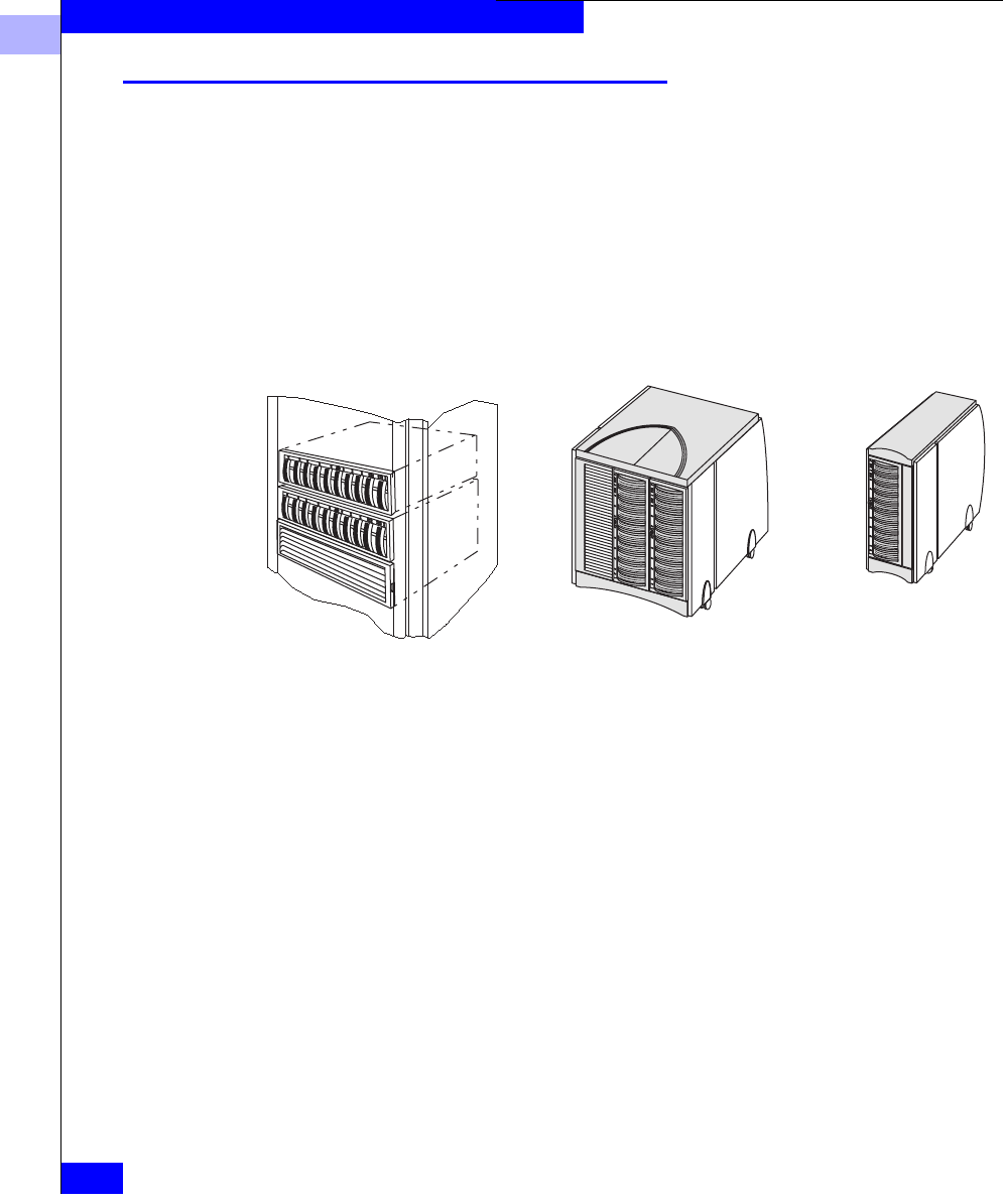
Figure 1-1 Storage System Models
1
Fibre Channel Background
1-3
About Fibre Channel Storage Systems and Networks (SANs)
Fibre Channel Background
Fibre Channel is a high-performance serial protocol that allows
transmission of both network and I/O channel data. It is a low level
protocol, independent of data types, and supports such formats as
SCSI and IP.
The Fibre Channel standard supports several physical topologies,
including switched fabric point-to-point and arbitrated loop (FC-AL).
The topologies used by the Fibre Channel storage systems described
in this manual are switched fabric and FC-AL.
A switch fabric is a set of point-to-point connections between nodes,
the connection being made through one or more Fibre Channel
switches. Each node may have its own unique address, but the path
between nodes is governed by a switch. The nodes are connected by
optical cable.
A Fibre Channel arbitrated loop is a circuit consisting of nodes. Each
node has a unique address, called a Fibre Channel arbitrated loop
address. The nodes are connected by optical cables. An optical cable
can transmit data over great distances for connections that span
entire enterprises and can support remote disaster recovery systems.
Copper cable serves well for local connections; its length is limited to
30 meters (99 feet).
Each connected device in a switched fabric or arbitrated loop is a
server adapter (initiator) or a target (storage system). The switches
and hubs are not considered nodes.
Figure 1-2 Nodes - Initiator and Target
EMC1802
Server Adapter (initiator)
Connection
Storage System (target)
Node
Adapter
Node
1
1-4
EMC Fibre Channel Storage-System Configuration Planning
About Fibre Channel Storage Systems and Networks (SANs)
Fibre Channel Storage Components
A Fibre Channel storage system has three main components:
•Server component (host-bus adapter driver package with adapter
and software)
•Interconnect components (cables based on Fibre Channel
standards, switches, and hubs)
•Storage components (storage system with storage processors —
SPs — and power supply and cooling hardware)
Server Component (Host-Bus Adapter Driver Package with Software)
The host-bus adapter driver package includes a host-bus adapter and
support software. The adapter is a printed-circuit board that slides
into an I/O slot in the server’s cabinet. It transfers data between
server memory and one or more disk-array storage systems over
Fibre Channel — as controlled by the support software (adapter
driver).
One or more servers can use a storage system. For high availability —
in event of an adapter failure — a server can have two adapters.
Depending on your server type, you may have a choice of adapters.
The adapter is designed for a specific host bus; for example, a PCI bus
or SBUS. Some adapter types support copper or optical cabling; some
support copper cabling only.
Interconnect Components
The interconnect components include the cables, Fibre Channel
switch (for shared storage), and Fibre Channel hub (for unshared
storage).
Cables Depending on your needs, you can choose copper or optical cables.
EMC1803
Adapter
Adapter
Server

1
Fibre Channel Storage Components
1-5
About Fibre Channel Storage Systems and Networks (SANs)
The maximum length of copper cable is 30 meters (99 feet) between
nodes or hubs. The maximum length of optical cable between server
and hub or storage system is much greater, depending on the cable
type. For example, 62.5-micron multimode cable can span up to 500
meters (1,640 feet) while 9-micron single-mode cable can span up to
10 kilometers (6.2 miles). This ability to span great distances is a
major advantage of optical cable.
Some nodes have connections that require a specific type of cable:
copper or optical. Other nodes allow for the conversion from copper
to optical using a conversion device called a GigaBit Interface
Converter (GBIC) or Media Interface Adapter (MIA). In most cases, a
GBIC or MIA lets you substitute long-distance optical connections for
shorter copper connections.
With extenders, optical cable can span up to 40 km (25 miles). This
ability to span great distances is a major advantage of optical cable.
Details on cable lengths and rules appear later in this manual.
Fibre Channel Switches
A Fibre Channel switch, which is a requirement for shared storage (a
Storage Area Network, SAN) connects all the nodes cabled to it using
a fabric topology. A switch adds serviceability and scalability to any
installation; it allows on-line insertion and removal of any device on
the fabric and maintains integrity if any connected device stops
participating. A switch also provides host-to-storage-system access
control in a multiple-host shared-storage environment. A switch has
several advantages over a hub: it provides point-to-point connections
(as opposed to a hub’s loop that includes all nodes) and it offers
zoning to specify paths between nodes in the switch itself.
1
1-6
EMC Fibre Channel Storage-System Configuration Planning
About Fibre Channel Storage Systems and Networks (SANs)
You can cascade switches (connect one switch port to another switch)
for additional port connections.
Figure 1-3 Switch and Hub Topologies Compared
Switch Zoning
Switch zoning defines paths between connected nodes. Each zone
encloses one or more adapters and one or more SPs. A switch can
have as many zones as it has ports. The current connection limits are
four SP ports to one adapter port (the SPs fan in to the adapter) and
15 adapters to one SP (the SPs fan out to the adapters). There are
several zone types, including the single-initiator type, which is the
recommended type.
In the following figure, Server 1 has access to one SP (SP A) in storage
systems 1 and 2; it has no access to any other SP.
S
witch uses discrete
c
onnections between
p
orts
SP SP
Server Server
Adapter
Storage systems
Adapter
Server
SP
Adapter
Switch topology (point-to-point)
Hub uses
loop between
ports
SP
Server Server
Adapter
Adapter
Server
Adapter
Hub topology (loop)
T
o illustrate the comparison, this figure shows just one adapter per server and one switch or
hub. Normally, such installations include two adapters per server and two switches or hubs.
1
Fibre Channel Storage Components
1-7
About Fibre Channel Storage Systems and Networks (SANs)
Figure 1-4 A Switch Zone
If you do not define a zone in a switch, all adapter ports connected to
the switch can communicate with all SP ports connected to the
switch. However, access to an SP does not necessarily provide access
to the SP’s storage; access to storage is governed by the Storage
Groups you create (defined later).
Fibre Channel switches are available with 16 or 8 ports. They are
compact units that fit in 2 U (3.5 inches) for the 16-port or 1 U (1.75
inches) for the 8-port. They are available to fit into a rackmount
cabinet or as small deskside enclosures.
Figure 1-5 16-Port Switch, Back View
SP SP
Server
1
Adapter
Storage system 1
Adapter
SP
Adapter
SP SP SP
Zone
Switch
Storage system 2 Storage system 3
fabric
To illustrate switch zoning, this figure shows just one HBA per server and one
switch or hub. Normally, such installations will include two HBAs per server
and two switches or hubs.
EMC1807
Ports
1
1-8
EMC Fibre Channel Storage-System Configuration Planning
About Fibre Channel Storage Systems and Networks (SANs)
If your servers and storage systems will be far apart, you can place
the switches closer to the servers or the storage systems, as
convenient.
A switch is technically a repeater, not a node, in a Fibre Channel loop.
However, it is bound by the same cabling distance rules as a node.
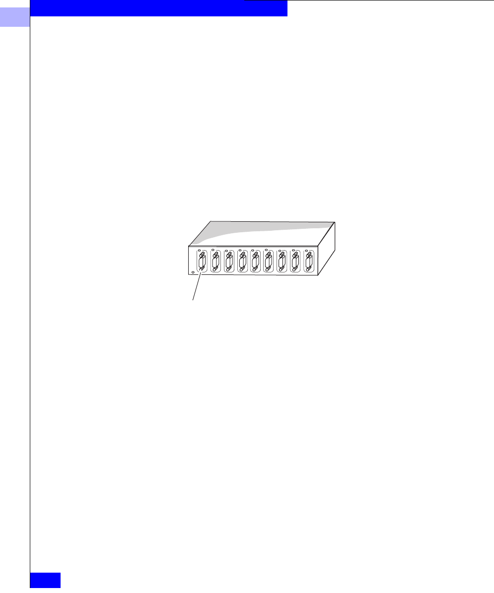
Fibre Channel Hubs A hub connects all the nodes cabled to it into a single logical loop. A
hub adds serviceability and scalability to any loop; it allows on-line
insertion and removal of any device on the loop and maintains loop
integrity if any connected device stops participating.
Fibre channel hubs are compact units that fit in 1 U (1.75 inches) of
storage space. They are available to fit into a rackmount cabinet or as
small deskside units.
Figure 1-6 Nine-Port Hub
If your servers and storage systems will be far apart, you can place
the hubs closer to the servers or the storage systems, as convenient.
The nine-pin port can connect to a server,
storage system, or another hub.
1
Fibre Channel Storage Components
1-9
About Fibre Channel Storage Systems and Networks (SANs)
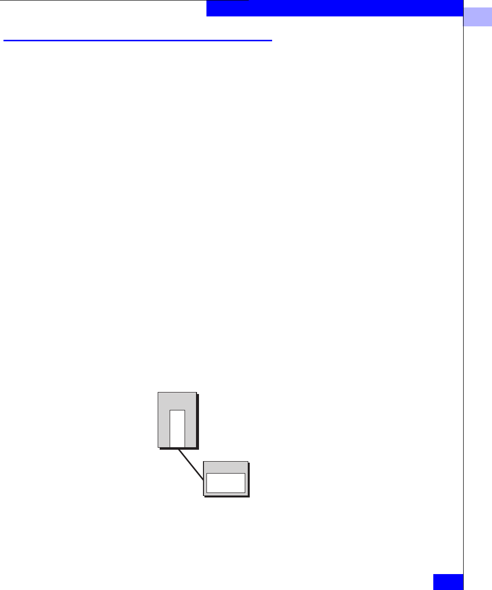
Storage Component (Storage Systems, Storage Processors (SPs), and Other
Hardware)
EMC disk-array storage systems, with their storage processors,
power supplies, and cooling hardware form the storage component
of a Fibre Channel system. The controlling unit, a Disk-array
Processor Enclosure (DPE) looks like the following figure.
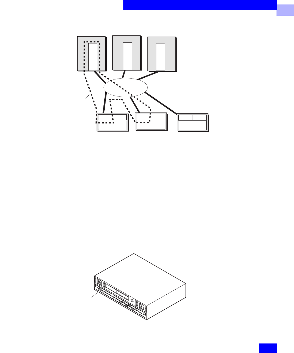
Figure 1-7 Disk-Array Processor Enclosure (DPE)
DPE hardware details appear in a later chapter.
EMC1808
Disk
modules
1
1-10
EMC Fibre Channel Storage-System Configuration Planning
About Fibre Channel Storage Systems and Networks (SANs)
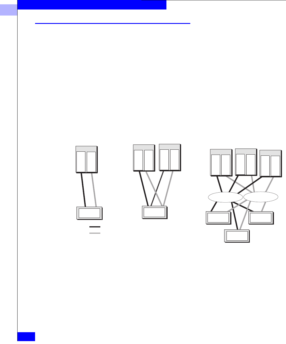
Types of Storage System Installations
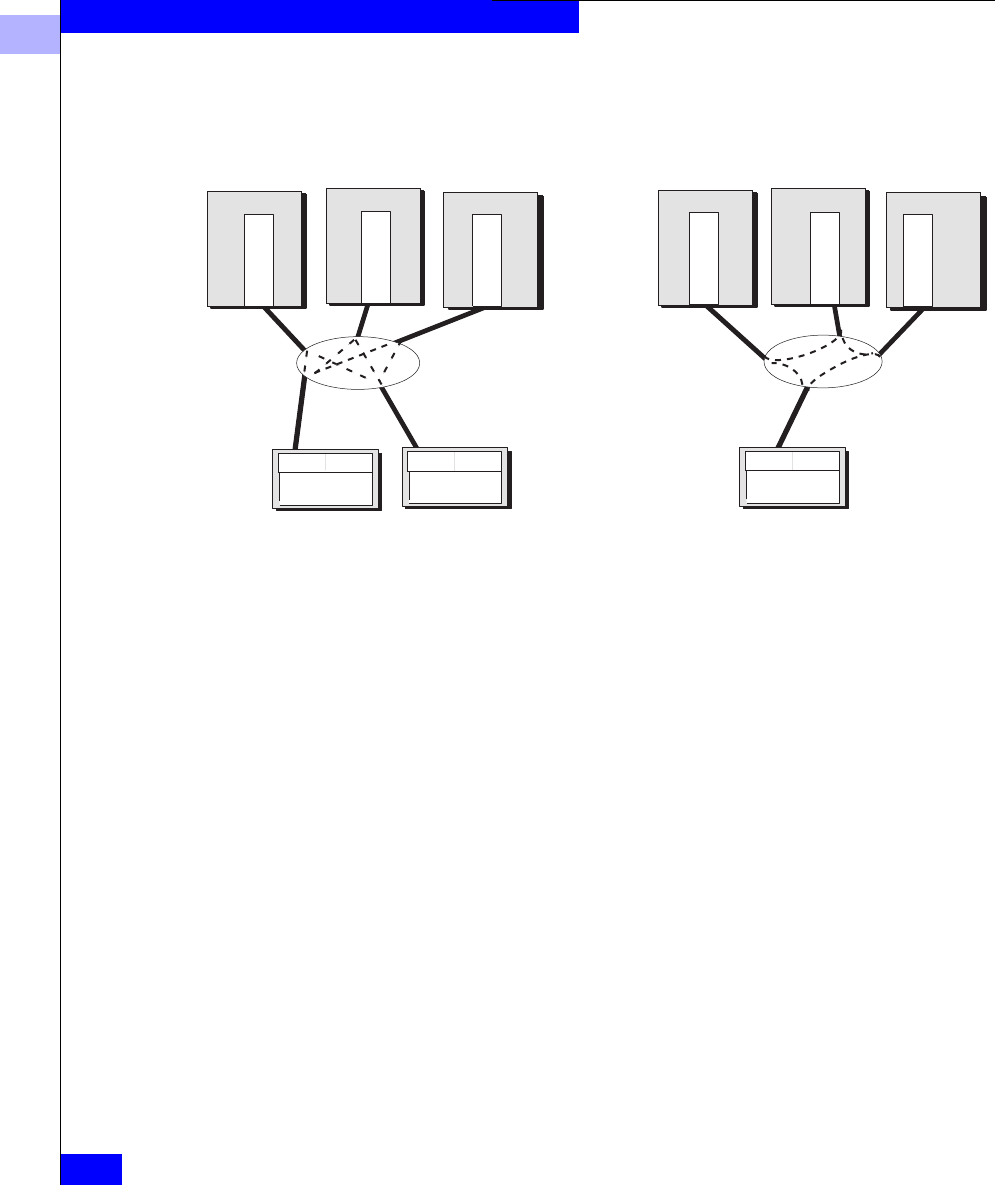
You can use a storage systems in any of several types of installation:
•Unshared direct with one server is the simplest and least costly;
•Shared-or-clustered direct lets two clustered servers share
storage resources with high availability (FC4500 storage systems;
and
•Shared switched, with one or two switch fabrics, lets two to 15
servers share the resources of several storage systems in a Storage
Area Network (SAN) Shared switched installations are available
in a high-availability (HA) version, with two HBAs per server,
with two switches, or with one HBA per server and one switch.
Figure 1-8 Types of Storage System Installation
Storage systems for any shared installation require EMC Access
Logix™ software to control server access to the storage system LUNs.
The Shared-or-clustered direct installation may be either shared (that
is, use Access Logix to control LUN access) or clustered (without
Access Logix, using cluster software to control LUN access),
depending on the hardware model.
Disk-array storage systems
Server
Adapter
Adapter
Server
Adapter
Adapter
Server
Adapter
Adapter
Server
Adapter
Adapter
Server
Adapter
Adapter
Server
Adapter
Adapter
Shared-or-Clustered Direct
(two servers)
Switch fabric Switch fabric
Shared Switched
(multiple servers)
Unshared Direct
(one or two servers)
Path 1
Path 2
1
About Switched Shared Storage and SANs (Storage Area Networks)
1-11
About Fibre Channel Storage Systems and Networks (SANs)
About Switched Shared Storage and SANs (Storage Area
Networks)
This section explains the features that let multiple servers share
disk-array storage systems on a SAN (storage area network).
A SAN is a collection of storage devices connected to servers via Fibre
Channel switches to provide a central location for disk storage.
Centralizing disk storage among multiple servers has many
advantages, including
•highly available data
•flexible association between servers and storage capacity
•centralized management for fast, effective response to users’ data
storage needs
•easier file backup and recovery
An EMC SAN is based on shared storage; that is, the SAN requires
the Access Logix option to provides flexible access control to storage
system LUNs.
Figure 1-9 Components of a SAN
Fibre Channel switches can control data access to storage systems
through the use of switch zoning. With zoning, an administrator can
specify groups (called zones) of Fibre Channel devices (such as
host-bus adapters, specified by worldwide name), and SPs between
which the switch will allow communication.
SP A
Server Server
SP B
Storage systems
Switch fabric
Adapter
Adapter
Adapter
Adapter
Adapter
Adapter
Server
SP A SP B
Switch fabric
Path 1
Path 2

1
1-12
EMC Fibre Channel Storage-System Configuration Planning
About Fibre Channel Storage Systems and Networks (SANs)
However, switch zoning cannot selectively control data access to
LUNs in a storage system, because each SP appears as a single Fibre
Channel device to the switch. So switch zoning can prevent or allow
communication with an SP, but not with specific disks or LUNs
attached to an SP. For access control with LUNs, a different solution is
required: Storage Groups.
Storage Groups A Storage Group is one or more LUNs (logical units) within a storage
system that is reserved for one or more servers and is inaccessible to
other servers. Storage Groups are the central component of shared
storage; storage systems that are unshared do not use Storage
Groups.
When you configure shared storage, you specify servers and the
Storage Group(s) each server can read from and/or write to. The Base
Software firmware running in each storage system enforces the
server-to-Storage Group permissions.
A Storage Group can be accessed by more than one server if all the
servers run cluster software. The cluster software enforces orderly
access to the shared Storage Group LUNs.
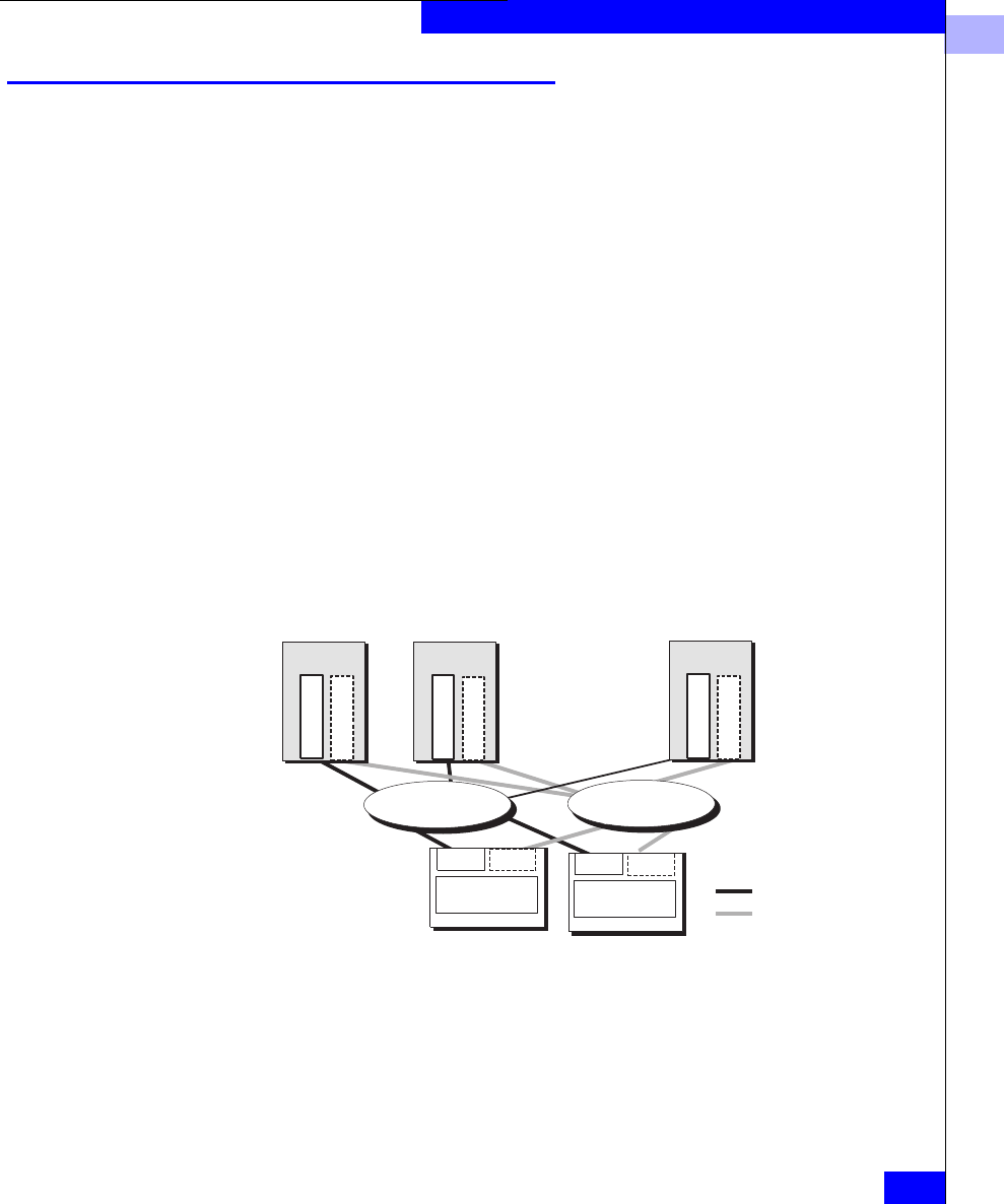
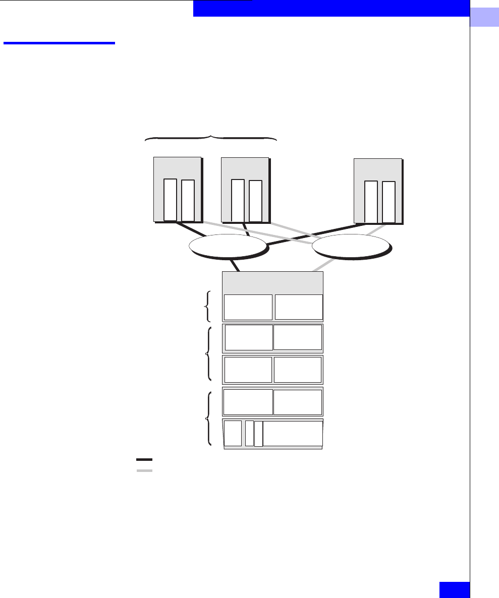
The following figure shows a simple shared storage configuration
consisting of one storage system with two Storage Groups. One
Storage Group serves a cluster of two servers running the same
operating system, and the other Storage Group serves a UNIX
database server. Each server is configured with two independent
paths to its data, including separate host-bus adapters, switches, and
SPs, so there is no single point of failure for access to its data.
1
About Switched Shared Storage and SANs (Storage Area Networks)
1-13
About Fibre Channel Storage Systems and Networks (SANs)
Figure 1-10 Sample SAN Configuration
Access Control with Shared Storage
Access control permits or restricts a server’s access to shared storage.
There are two kinds of access control:
•Configuration access control
•Data access control
Configuration access control lets you restrict the servers through
which a user can send configuration commands to an attached
storage system.
Data access control is provided by Storage Groups. During storage
system configuration, using a management utility, the system
administrator associates a server with one or more LUNs.
Each server sees its Storage Group as if it were an entire storage
system, and never sees the other LUNs on the storage system.
Therefore, it cannot access or modify data on LUNs that are not part
of its Storage Group. However, you can define a Storage Group to be
accessible by more than one server, if, as shown above, the servers
run cluster software.
Highly available cluster
SP A
LUN
LUN
LUN
LUN
LUN
LUN
LUN
Cluster
Storage Group
Database Server
Storage Group
Physical storage
systems with up to
100 disks per storage
system
Switch fabric
File Server Mail Server Database Server
Adapter
Adapter
Operating
system A
Adapter
Adapter
Operating
system A
Adapter
Adapter
Operating
system B
SP B
Switch fabric
Path 1
Path 2
1
1-14
EMC Fibre Channel Storage-System Configuration Planning
About Fibre Channel Storage Systems and Networks (SANs)
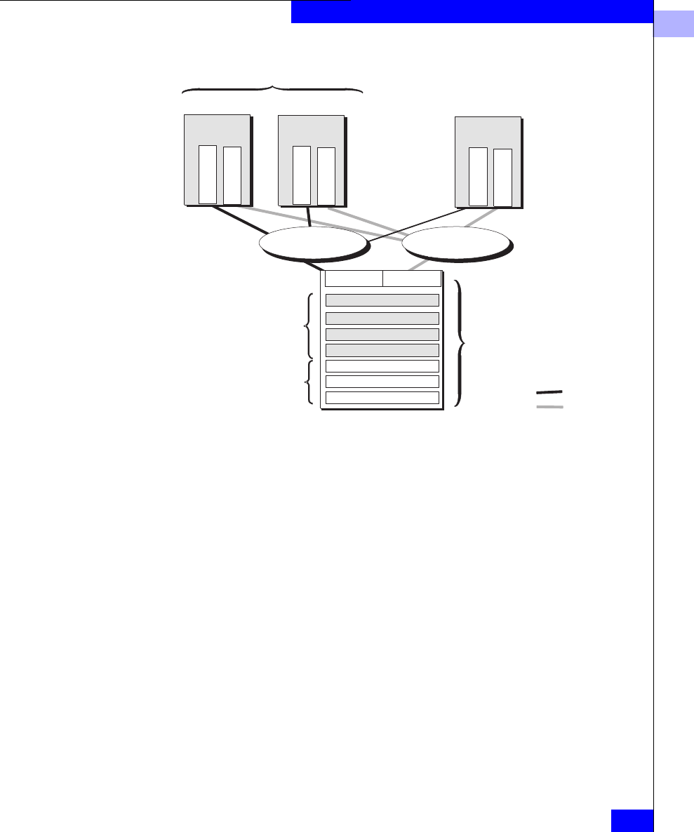
The following figure shows both data access control (Storage Groups)
and configuration access control. Each server has exclusive read and
write access to its designated Storage Group. Of the four servers
connected to the SAN, only the Admin server can send configuration
commands to the storage system.
Figure 1-11 Data and Configuration Access Control with Shared Storage
Admin Storage Group LUN
LUN
LUN
LUN
LUN
LUN
LUN
LUN
LUN
LUN
Inventory Storage Group
E-mail and Web server
Storage Group
SP B
Highly available cluster
Data access by adapters 01, 02
Data access by adapters 03, 04
Data access by
adapters 05, 06, 07, 08
Shared
Dedicated
Dedicated
Configuation access, by
adapters 01and 02
(Admin server only)
Switch fabric
SP A
Web server
Inventory server E-mail server
Admin server
Adapter
Adapter
03 04
Operating
system A
Adapter
Adapter
01 02
Operating
system A
Adapter
Adapter
05 06
Operating
system B
Adapter
Adapter
07 08
Operating
system B
Switch fabric
1
About Switched Shared Storage and SANs (Storage Area Networks)
1-15
About Fibre Channel Storage Systems and Networks (SANs)
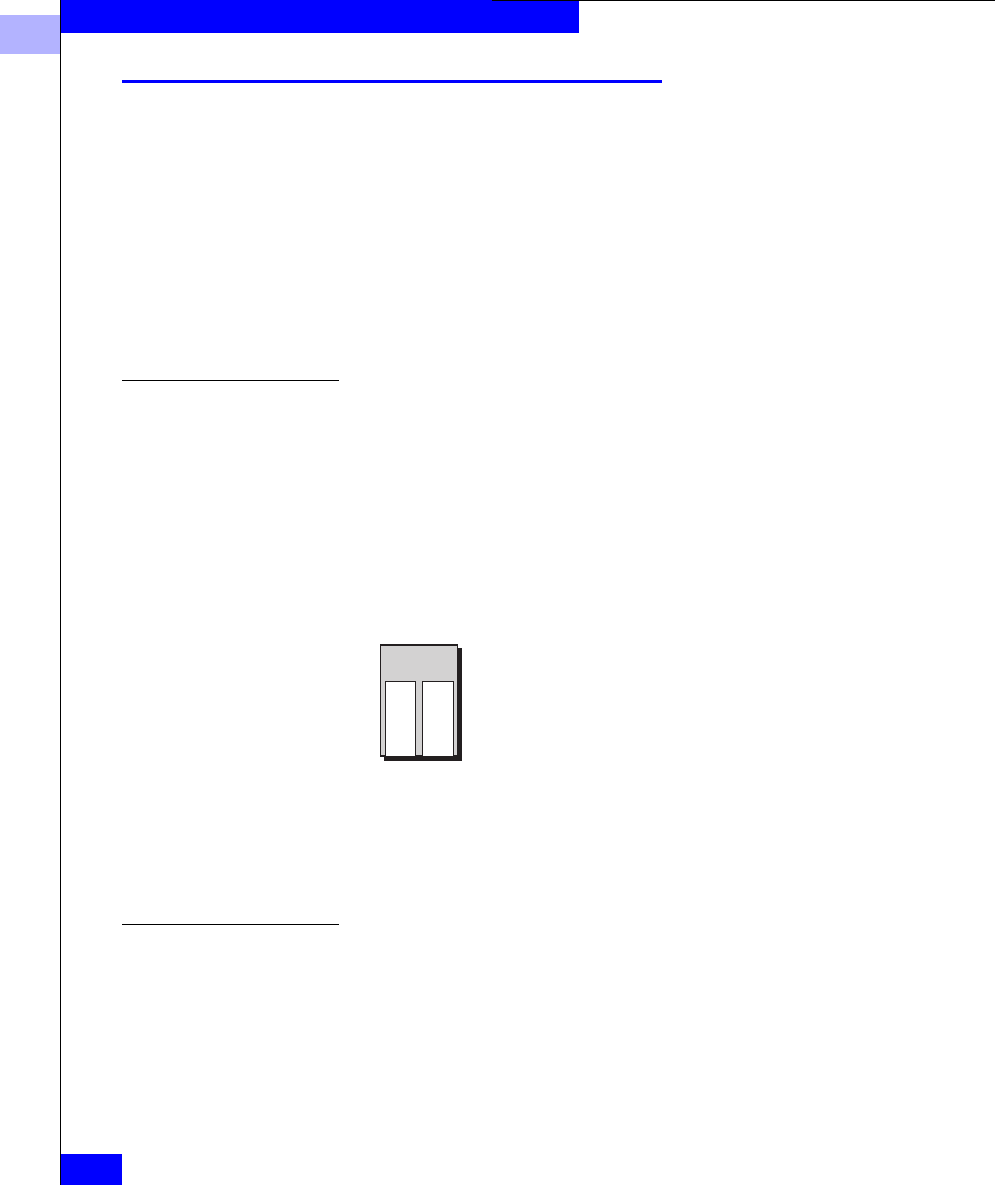
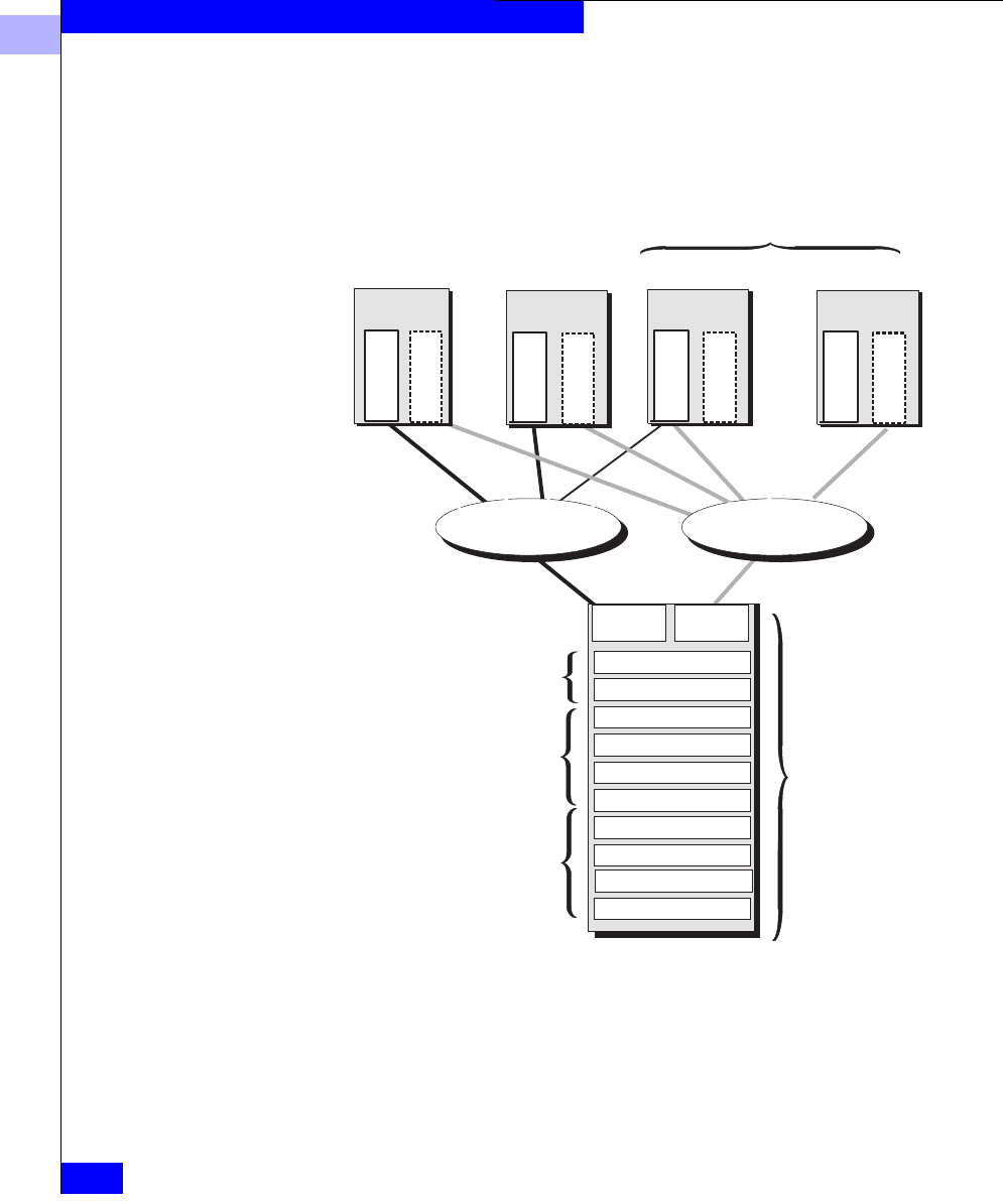
Storage System Hardware for Shared Storage
For shared storage, you need a Disk-array Processor Enclosure (DPE)
storage system.
A DPE is a 10-slot enclosure with hardware RAID features provided
by one or two storage processors (SPs). For shared storage, two SPs
are required. In addition to its own disks, a DPE can support up to
nine 10-slot Disk Array Enclosures (DAEs) for a total of 100 disks.
Figure 1-12 Storage System with a DPE and Three DAEs
EMC1741
DPE
DAE
DAE
DAE
Standby power
supply (SPS)

1
1-16
EMC Fibre Channel Storage-System Configuration Planning
About Fibre Channel Storage Systems and Networks (SANs)
About Unshared Storage
Unshared storage systems are less costly and less complex than
shared storage systems. They offer many shared storage system
features; for example, you can use multiple unshared storage systems
with multiple servers. However, with multiple servers, unshared
storage offers less flexibility and security than shared storage, since
any user with write access to a privileged server’s files can enable
access to any storage system.
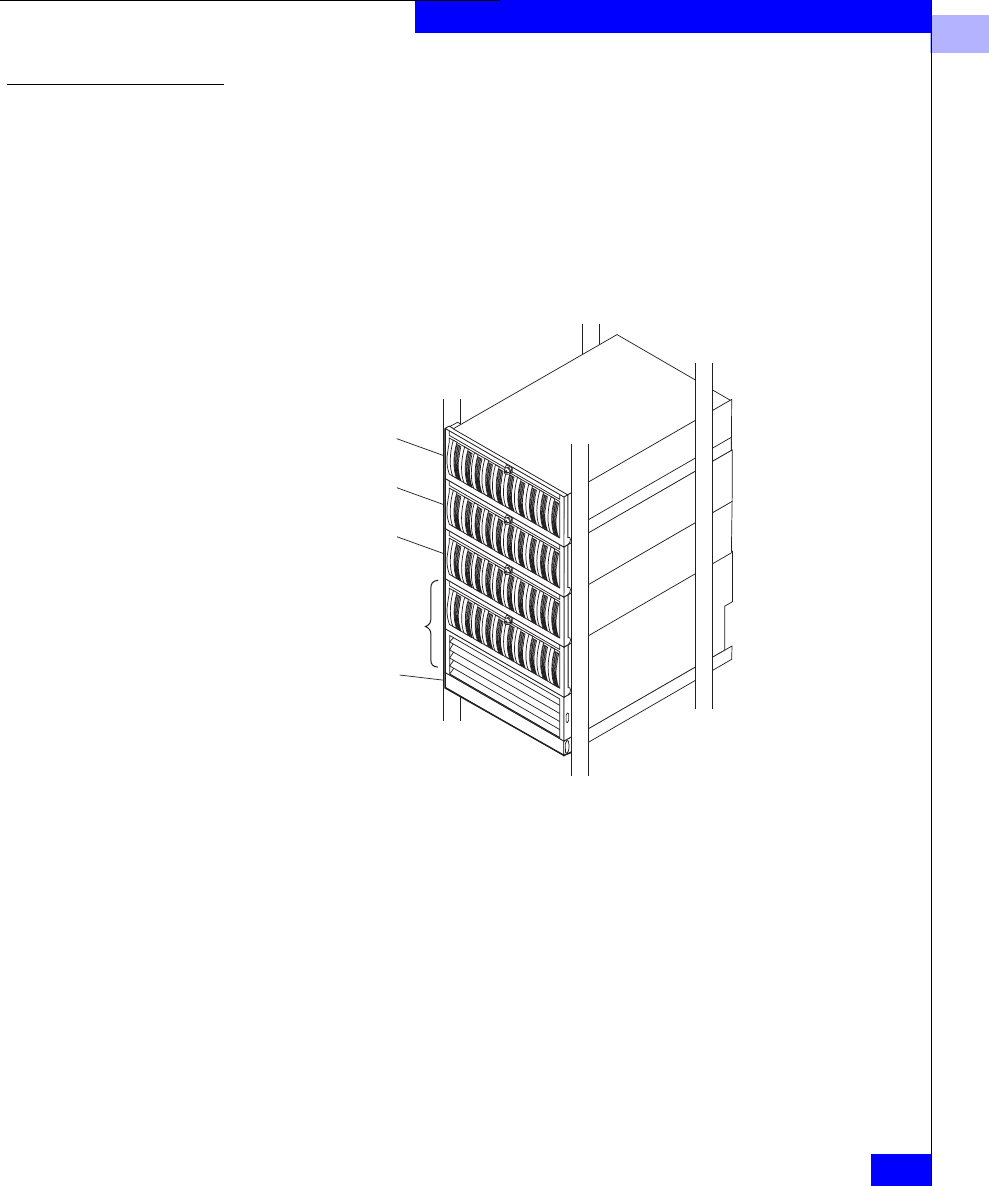
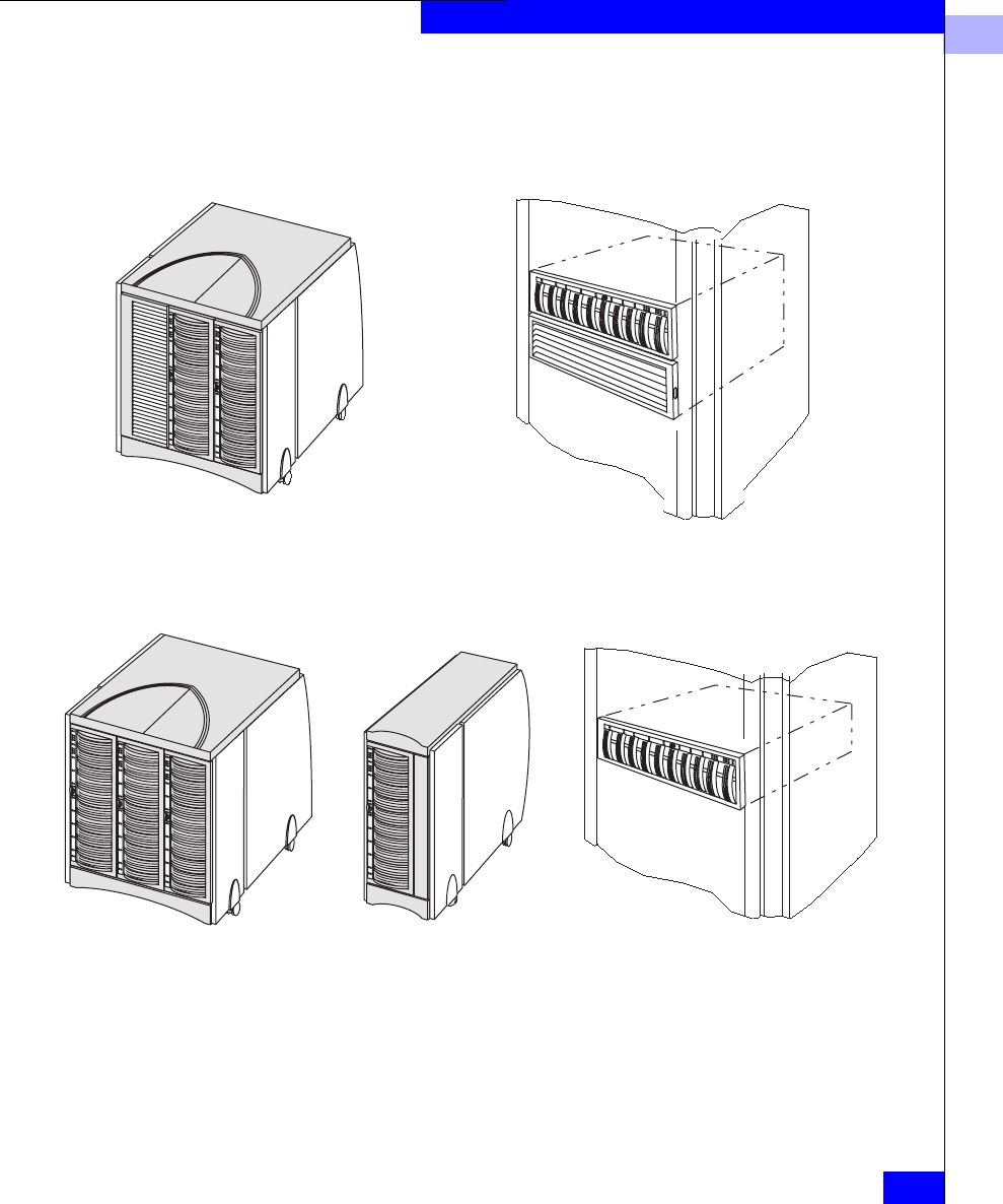
Storage System Hardware for Unshared Storage
For unshared storage, there are four types of storage system, each
using the FC-AL protocol. Each type is available in a rackmount or
deskside (office) version.
•Disk-array Processor Enclosure (DPE) storage systems. A DPE is
a 10-slot enclosure with hardware RAID features provided by one
or two storage processors (SPs). In addition to its own disks, a
DPE can support up to 110 additional disks in 10-slot Disk Array
Enclosures (DAEs) for a total of 120 disks. This is the same type of
storage system used for shared storage, but it has a different SP
and different Core Software.
•Intelligent Disk Array Enclosure (iDAE). An iDAE, like a DPE,
has SPs and thus all the features of a DPE, but is thinner and has a
limit of 30 disks.
•Disk Array Enclosure (DAE). A DAE does not have SPs. A DAE
can connect to a DPE or an iDAE, or you can use it without SPs. A
DAE used without an SP does not inherently include RAID, but
can operate as a RAID device using software running on the
server system. Such a DAE is also known as Just a Box of Disks, or
JBOD.
1
About Unshared Storage
1-17
About Fibre Channel Storage Systems and Networks (SANs)
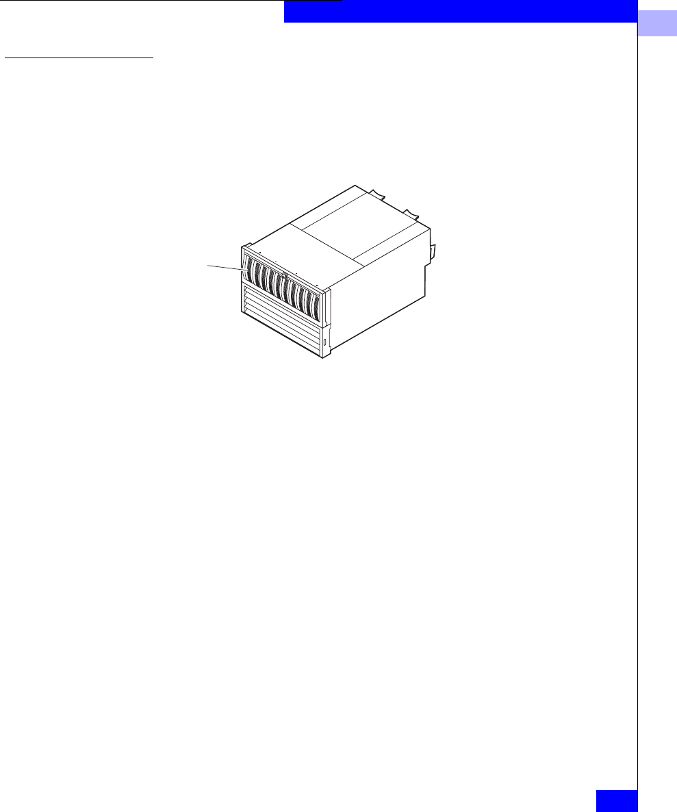
Figure 1-13 Storage System Hardware for Unshared Storage
What Next? For information about RAID types and RAID tradeoffs, continue to
the next chapter. To plan LUNs and file systems for shared storage,
skip to Chapter 3; or for unshared storage, Chapter 4. For details on
the storage-system hardware — shared and unshared — skip to
Chapter 5. For storage-system management utilities, skip to
Chapter 6.
Deskside DPE with DAE Rackmount DPE, one enclosure,
supports up to 9 DAEs
Disk-array processor enclosure (DPE)
Intelligent disk-array enclosure (iDAE)
30-slot deskside Rackmount10-slot deskside

1
1-18
EMC Fibre Channel Storage-System Configuration Planning
About Fibre Channel Storage Systems and Networks (SANs)

RAID Types and Tradeoffs
2-1
2
This chapter explains RAID types you can choose for your storage
system LUNs. If you already know about RAID types and know
which ones you want, you can skip this background information and
skip to Chapter 5. Topics are
•Introducing RAID ..............................................................................2-2
•RAID Types.........................................................................................2-4
•RAID Benefits and Tradeoffs..........................................................2-12
•Guidelines for RAID Types.............................................................2-17
•Sample Applications for RAID Types...........................................2-19
This chapter applies primarily to storage systems with storage processors
(SPs). For a storage system without SPs (a DAE-only or JBOD system), RAID
types are limited by the RAID software you run on the server. The RAID
terms and definitions used here conform to generally accepted standards.
RAID Types and
Tradeoffs

2
2-2
EMC Fibre Channel Storage-System Configuration Planning
RAID Types and Tradeoffs
Introducing RAID
The storage system uses RAID (redundant array of independent
disks) technology. RAID technology groups separate disks into one
logical unit (LUN) to improve reliability and/or performance.
The storage system supports five RAID levels and two other disk
configurations, the individual unit and the hot spare (global spare).
You group the disks into one RAID Group by binding them using a
storage-system management utility.
Four of the RAID types use disk striping and two use mirroring.
Disk Striping Using disk stripes, the storage-system hardware can read from and
write to multiple disks simultaneously and independently. By
allowing several read/write heads to work on the same task at once,
disk striping can enhance performance. The amount of information
read from or written to each disk makes up the stripe element size.
The stripe size is the stripe element size multiplied by the number of
disks in a group. For example, assume a stripe element size of 128
sectors (the default) and a five-disk group. The group has five disks,
so you would multiply five by the stripe element size of 128 to yield a
stripe size of 640 sectors.
The storage system uses disk striping with most RAID types.
Mirroring Mirroring maintains a second (and optionally through software, a
third) copy of a logical disk image that provides continuous access if
the original image becomes inaccessible. The system and user
applications continue running on the good image without
interruption. There are two kinds of mirroring: hardware mirroring,
in which the SP synchronizes the disk images; and software
mirroring, in which the operating system synchronizes the images.
Software mirroring consumes server resources, since the operating
system must mirror the images, and has no offsetting advantages; we
mention it here only for historical completeness.
With a storage system, you can create a hardware mirror by binding
disks as a RAID 1 mirrored pair or a RAID 1/0 Group (a mirrored
RAID 0 Group); the hardware will then mirror the disks
automatically.
2
Introducing RAID
2-3
RAID Types and Tradeoffs
RAID Groups and
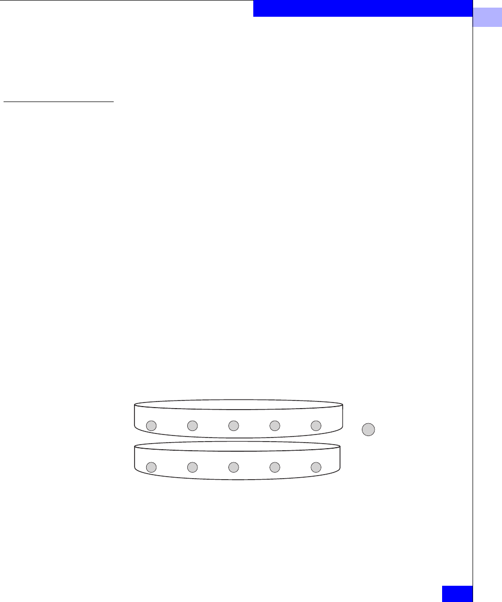
LUNs Some RAID types let you create multiple LUNs on one RAID Group.
You can then allot each LUN to a different user, server, or application.
For example, a five-disk RAID 5 Group that uses 36-Gbyte disks
offers 144 Gbytes of space. You could bind three LUNs, say with 24,
60, and 60 Gbytes of storage capacity, for temporary, mail, and
customer files.
One disadvantage of multiple LUNs on a RAID Group is that I/O to
each LUN may affect I/O to the others in the group; that is, if traffic
to one LUN is very heavy, I/O performance with other LUNs may
degrade. The main advantage of multiple LUNs per RAID Group is
the ability to divide the enormous amount of disk space provided by
RAID Groups on newer, high-capacity disks.
Figure 2-1 Multiple LUNs in a RAID Group
EMC1814
RAID Group
Disk Disk Disk Disk Disk
LUN 0
temp
LUN 1
mail
LUN 2
customers
LUN 0
temp
LUN 1
mail
LUN 2
customers
LUN 0
temp
LUN 1
mail
LUN 2
customers
LUN 0
temp
LUN 1
mail
LUN 2
customers
LUN 0
temp
LUN 1
mail
LUN 2
customers

2
2-4
EMC Fibre Channel Storage-System Configuration Planning
RAID Types and Tradeoffs
RAID Types
You can choose from the following RAID types: RAID 5, RAID 3,
RAID 1, RAID 0, RAID 1/0, individual disk unit, and hot spare.
RAID 5 Group (Individual Access Array)
A RAID 5 Group usually consists of five disks (but can have three to
sixteen). A RAID 5 Group uses disk striping. With a RAID 5 Group on
a full-fibre storage system, you can create up to 32 RAID 5 LUNs to
apportion disk space to different users, servers, and applications.
The storage system writes parity information that lets the group
continue operating if a disk fails. When you replace the failed disk,
the SP rebuilds the group using the information stored on the
working disks. Performance is degraded while the SP rebuilds the
group. However, the storage system continues to function and gives
users access to all data, including data stored on the failed disk.
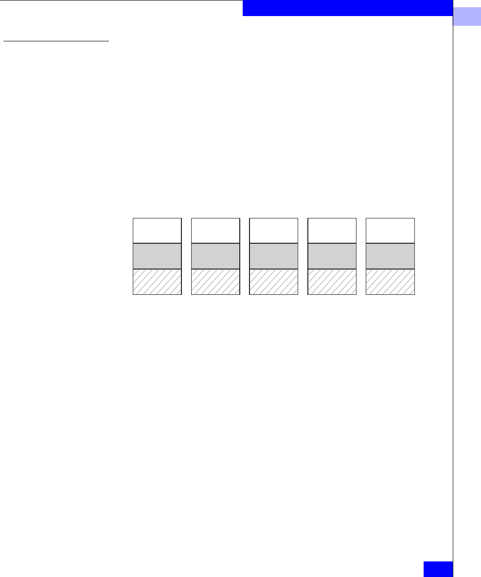
The following figure shows user and parity data with the default
stripe element size of 128 sectors (65,536 bytes) in a five-disk RAID 5
Group. The stripe size comprises all stripe elements. Notice that the
disk block addresses in the stripe proceed sequentially from the first
disk to the second, third, and fourth, then back to the first, and so on.
2
RAID Types
2-5
RAID Types and Tradeoffs
Figure 2-2 RAID 5 Group
RAID 5 Groups offer excellent read performance and good write
performance. Write performance benefits greatly from
storage-system caching.
RAID 3 Group (Parallel Access Array)
A RAID 3 Group consists of five or more disks. The hardware always
reads from or writes to all the disks. A RAID 3 Group uses disk
striping. To maintain the RAID 3 performance, you can create only
one LUN per RAID 3 Group.
The storage system writes parity information that lets the group
continue operating if a disk fails. When you replace the failed disk,
the SP rebuilds the group using the information stored on the
working disks. Performance is degraded while the SP rebuilds the
group. However, the storage system continues to function and gives
users access to all data, including data stored on the failed disk.
EMC1815
Second disk
128-255 640-767 1152-1279 Parity 2048-2175
Parity
Third disk
256-383 768-895 1664-1791 2176-2303
Parity Fourth disk
384-511 1280-1407 1792-1919 2304-2431
Parity Fifth disk
896-1023 1408-1535 1920-2047 2432-2559
Stripe
Stripe
element
size
Stripe
size
First disk
512-639 1024-11511536-1663 Parity
0-127
Blocks
User data
Parity data
…
…
…
…
…
2
2-6
EMC Fibre Channel Storage-System Configuration Planning
RAID Types and Tradeoffs
The following figure shows user and parity data with a data block
size of 2 Kbytes in a RAID 3 Group. Notice that the byte addresses
proceed from the first disk to the second, third, and fourth, then the
first, and so on.
Figure 2-3 RAID 3 Group
RAID 3 differs from RAID 5 in several important ways. First, in a
RAID 3 Group the hardware processes disk requests serially; whereas
in a RAID 5 Group the hardware can interleave disk requests. Second,
with a RAID 3 Group, the parity information is stored on one disk;
with a RAID 5 Group, it is stored on all disks. Finally, with a RAID 3
Group, the I/O occurs in small units (one sector) to each disk. A
RAID 3 Group works well for single-task applications that use I/Os
of blocks larger than 64 Kbytes.
Each RAID 3 Group requires some dedicated SP memory (6 Mbytes
recommended per group). This memory is allocated when you create
the group and becomes unavailable for storage-system caching. For
top performance, we suggest that you do not use RAID 3 Groups
with RAID 5, RAID 1/0, or RAID 0 Groups, since SP processing
power and memory are best devoted to the RAID 3 Groups. RAID 1
mirrored pairs and individual units require less SP processing power,
and therefore work well with RAID 3 Groups.
EMC1816
Second disk
Third disk
Fourth disk
Fifth disk
Stripe
element
size
Stripe
size
…
…
…
…
…
First disk
User data
Parity data
2048-2559 4096-4607 6144-6655 8192-8603
0-511
512-1023 2560-3071 4608-5119 6656-7167 8604-9115
5120-56311024-1535 3072-3583 7168-7679 9116-9627
3584-40951536-2047 5632-6143 7680-81919628-10139
Parity Parity Parity Parity Parity
Data block
Bytes
2
RAID Types
2-7
RAID Types and Tradeoffs
For each write to a RAID 3 Group, the storage system
1. Calculates the parity data.
2. Writes the new user and parity data.
RAID 1 Mirrored Pair A RAID 1 Group consists of two disks that are mirrored
automatically by the storage-system hardware.
RAID 1 hardware mirroring within the storage system is not the same
as software mirroring or hardware mirroring for other kinds of disks.
Functionally, the difference is that you cannot manually stop
mirroring on a RAID 1 mirrored pair, and then access one of the
images independently. If you want to use one of the disks in such a
mirror separately, you must unbind the mirror (losing all data on it),
rebind the disk in as the type you want, and software format the
newly bound LUN.
With a storage system, RAID 1 hardware mirroring has the following
advantages:
•automatic operation (you do not have to issue commands to
initiate it)
•physical duplication of images
•a rebuild period that you can select during which the SP recreates
the second image after a failure
With a RAID 1 mirrored pair, the storage system writes the same data
to both disks, as follows.
Figure 2-4 RAID 1 Mirrored Pair
EMC1817
Second disk
…
…
First disk
User data
1
1
2
2
3
3
4
4
0
0

2
2-8
EMC Fibre Channel Storage-System Configuration Planning
RAID Types and Tradeoffs
RAID 0 Group (Nonredundant Array)
A RAID 0 Group consists of three to a maximum of sixteen disks. A
RAID 0 Group uses disk striping, in which the hardware writes to or
reads from multiple disks simultaneously. In a full-fibre storage
system, you can create up to 32 LUNs per RAID Group.
Unlike the other RAID levels, with RAID 0 the hardware does not
maintain parity information on any disk; this type of group has no
inherent data redundancy. RAID 0 offers enhanced performance
through simultaneous I/O to different disks.
If the operating system supports software mirroring, you can use
software mirroring with the RAID 0 Group to provide high
availability. A desirable alternative to RAID 0 is RAID 1/0.
RAID 1/0 Group (Mirrored RAID 0 Group)
A RAID 1/0 Group consists of four, six, eight, ten, twelve, fourteen,
or sixteen disks. These disks make up two mirror images, with each
image including two to eight disks. The hardware automatically
mirrors the disks. A RAID 1/0 Group uses disk striping. It combines
the speed advantage of RAID 0 with the redundancy advantage of
mirroring. With a RAID 1/0 Group on a full-fibre storage system, you
can create up to 32 RAID 5 LUNs to apportion disk space to different
users, servers, and applications.
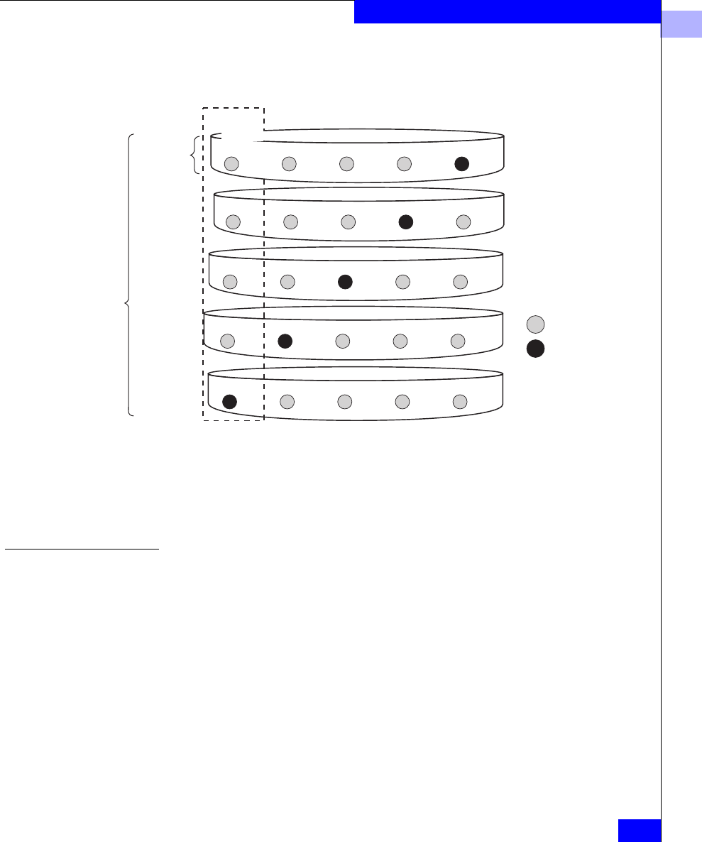
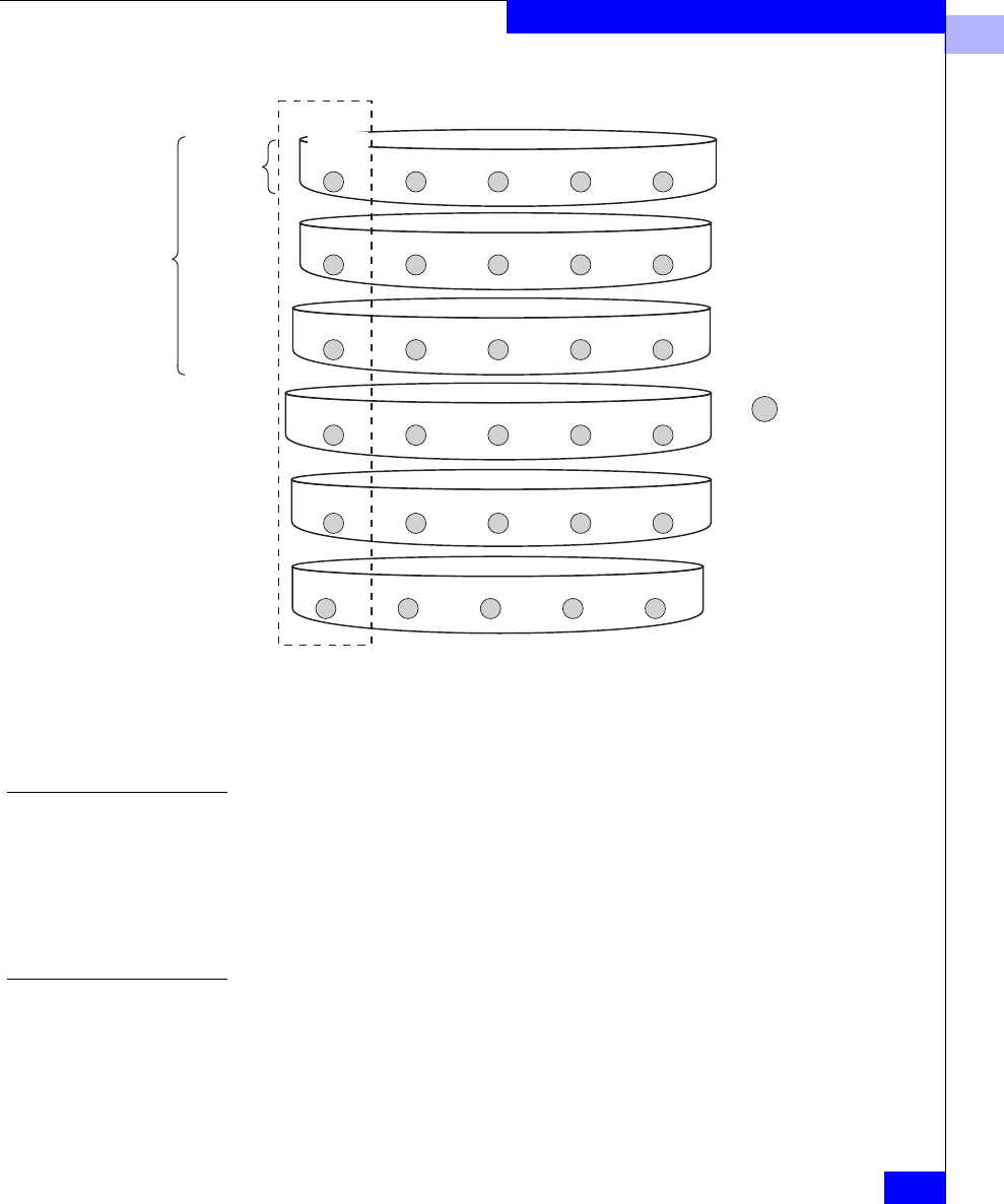
The following figure shows the distribution of user data with the
default stripe element size of 128 sectors (65,536 bytes) in a six-disk
RAID 1/0 Group. Notice that the disk block addresses in the stripe
proceed sequentially from the first mirrored disks (first and fourth
disks) to the second mirrored disks (second and fifth disks), to the
third mirrored disks (third and sixth disks), and then from the first
mirrored disks, and so on.
2
RAID Types
2-9
RAID Types and Tradeoffs
Figure 2-5 RAID 1/0 Group (Mirrored RAID 0 Group)
A RAID 1/0 Group can survive the failure of multiple disks,
providing that one disk in each image pair survives.
Individual Disk Unit An individual disk unit is a disk bound to be independent of any
other disk in the cabinet. An individual unit has no inherent high
availability, but you can make it highly available by using software
mirroring with another individual unit. You can create one LUN per
individual disk unit. If you want to apportion the disk space, you can
do so using partitions, file systems, or user directories.
Hot Spare A hot spare is a dedicated replacement disk on which users cannot
store information. A hot spare is global: if any disk in a RAID 5
Group, RAID 3 Group, RAID 1 mirrored pair, or RAID 1/0 Group
fails, the SP automatically rebuilds the failed disk’s structure on the
hot spare. When the SP finishes rebuilding, the disk group functions
as usual, using the hot spare instead of the failed disk. When you
EMC1818
Stripe
element
size
Stripe
size …
…
…
…
…
User data
First disk of primary image
Second disk of primary image
Third disk of primary image
Third disk of secondary image
First disk of secondary image
Second disk of secondary image
512-639128-255 1664-17911280-1407896-1023
1536-16631152-1279768-895
…
512-639
1024-1151
1024-1151
1536-16630-127
128-255
640-767
640-767
1152-1279
256-383
256-383
768-895
1664-1791
384-511
1280-1407
1792-1919
1792-1919
896-1023
1408-1535
1408-1535
Stripe
Blocks
0-127 384-511

2
2-10
EMC Fibre Channel Storage-System Configuration Planning
RAID Types and Tradeoffs
replace the failed disk, the SP copies the data from the former hot
spare onto the replacement disk.
When the copy is done, the disk group consists of disks in the original
slots, and the SP automatically frees the hot spare to serve as a hot
spare again. A hot spare is most useful when you need the highest
data availability. It eliminates the time and effort needed for someone
to notice that a disk has failed, find a suitable replacement disk, and
insert the disk.
When you plan to use a hot spare, make sure the disk has the capacity to
serve in any RAID Group in the storage-system chassis. A RAID Group
cannot use a hot spare that is smaller than a failed disk in the group.
You can have one or more hot spares per storage-system chassis. You
can make any disk in the chassis a hot spare, except for a disk that
serves for Core Software storage or the write cache vault. That is, a
hot spare can be any of the following disks:
An example of hot spare usage for a deskside DPE storage system
follows.
DPE or iDAE system without write caching: disks 3-119
DPE system with write caching: disks 9-119
iDAE system with write caching: disks 5-29
30-slot SCSI-disk system: disks A1-E1, A2-E2,
B3-E3, A4-E4
2
RAID Types
2-11
RAID Types and Tradeoffs
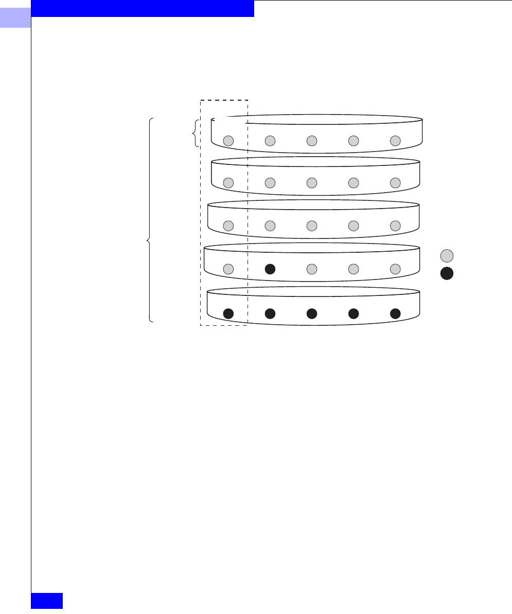
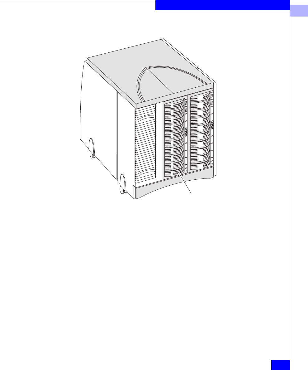
Figure 2-6 How a Hot Spare Works
Hot spare
0
1
2
3
4
5
6
7
8
9
10
11
12
13
14
15
16
17
18
19
1. RAID 5 group consists of disk modules 0-4; RAID 1 mirrored pair is
modules 5 and 6; hot spare is module 9.
2. Disk module 3 fails.
3. RAID 5 group becomes modules 0, 1, 2, 9, and 4; now no hot spare is
available.
4. System operator replaces failed module 3 with a functional module.
5. RAID 5 group once again is 0-4 and hot spare is 9.

2
2-12
EMC Fibre Channel Storage-System Configuration Planning
RAID Types and Tradeoffs
RAID Benefits and Tradeoffs
This section reviews RAID types and explains their benefits and
tradeoffs. You can create seven types of LUN:
•RAID 5 Group (individual access array)
•RAID 3 Group (parallel access array)
•RAID 1 mirrored pair
•RAID 1/0 Group (mirrored RAID 0 Group); a RAID 0 Group
mirrored by the storage-system hardware
•RAID 0 Group (nonredundant individual access array); no
inherent high-availability features, but can be software mirrored
if the operating system supports mirroring
•Individual unit; no inherent high-availability features but can be
software mirrored, if the operating system supports mirroring
•Hot spare; serves only as an automatic replacement for any disk
in a RAID type other than 0; does not store data during normal
system operations
Plan the disk unit configurations carefully. After a disk has been bound into a
LUN, you cannot change the RAID type of that LUN without unbinding it,
and this means losing all data on it.
The following table compares the read and write performance,
tolerance for disk failure, and relative cost per megabyte (Mbyte) of
the RAID types. Figures shown are theoretical maximums.

2
RAID Benefits and Tradeoffs
2-13
RAID Types and Tradeoffs
Table 2-1 Performance, Availability, and Cost of RAID Types (Individual Unit = 1.0)
Performance RAID 5, with individual access, provides high read throughput for
small requests (blocks of 2 to 8 Kbytes) by allowing simultaneous
reads from each disk in the group. RAID 5 write throughput is
limited by the need to perform four I/Os per request (I/Os to read
and write data and parity information). However, write caching
improves RAID 5 write performance.
RAID 3, with parallel access, provides high throughput for
sequential, large block-size requests (blocks of more than 64 Kbytes).
With RAID 3, the system accesses all five disks in each request but
need not read data and parity before writing – advantageous for large
requests but not for small ones. RAID 3 employs SP memory without
caching, which means you do not need the second SP and BBU that
caching requires.
Generally, the performance of a RAID 3 Group increases as the size of
the I/O request increases. Read performance increases rapidly with
read requests up to 1Mbyte. Write performance increases greatly for
sequential write requests that are greater than 256 Kbytes. For
applications issuing very large I/O requests, a RAID 3 LUN provides
significantly better write performance than a RAID 5 LUN.
Disk configuration
Relative read
performance
without cache
Relative write
performance
without cache
Relative
cost per
Mbyte
RAID 5 Group with
fivedisks
Up to 5 with five disks
(for small I/O requests, 2
to 8 Kbytes)
Up to 1.25 with five disks
(for small I/O requests, 2 to
8 Kbytes)
1.25
RAID 3 Group with
fivedisks
Up to 4 (for large I/O
requests)
Up to 4 (for large I/O
requests)
1.25
RAID 1 mirrored pair Up to 2 Up to 1 2
RAID 1/0 Group with
10 disks
Up to 10 Up to 5
Individual unit 1 1 1
Notes: These performance numbers are not based on storage-system caching. With caching,
the performance numbers for RAID 5 writes improve significantly.
Performance multipliers vary with load on server and storage system.

2
2-14
EMC Fibre Channel Storage-System Configuration Planning
RAID Types and Tradeoffs
We do not recommend using RAID 3 in the same storage-system
chassis with RAID 5 or RAID 1/0.
A RAID 1 mirrored pair has its disks locked in synchronization, but
the SP can read data from the disk whose read/write heads are closer
to it. Therefore, RAID 1 read performance can be twice that of an
individual disk while write performance remains the same as that of
an individual disk.
A RAID 0 Group (nonredundant individual access array) or RAID
1/0 Group (mirrored RAID 0 Group) can have as many I/O
operations occurring simultaneously as there are disks in the group.
Since RAID 1/0 locks pairs of RAID 0 disks the same way as RAID 1
does, the performance of RAID 1/0 equals the number of disk pairs
times the RAID 1 performance number. If you want high throughput
for a specific LUN, use a RAID 1/0 or RAID 0 Group. A RAID 1/0
Group requires at least six disks; a RAID 0 Group, at least three disks.
An individual unit needs only one I/O operation per read or write
operation.
RAID types 5, 1, 1/0, and 0 allow multiple LUNs per RAID Group. If
you create multiple LUNs on a RAID Group, the LUNs share the
RAID Group disks, and the I/O demands of each LUN affect the I/O
service time to the other LUNs. For best performance, you may want
to use one LUN per RAID Group.
Storage Flexibility Certain RAID Group types — RAID 5, RAID 1, RAID 1/0, and RAID
0 — let you create up to 32 LUNs in each group. This adds flexibility,
particularly with large disks, since it lets you apportion LUNs of
various sizes to different servers, applications, and users. Conversely,
with RAID 3, there can be only one LUN per RAID Group, and the
group must include five or nine disks — a sizable block of storage to
devote to one server, application, or user. However, the nature of
RAID 3 makes it ideal for that single-threaded type of application.
Data Availability and Disk Space Usage
If data availability is critical and you cannot afford to wait hours to
replace a disk, rebind it, make it accessible to the operating system,
and load its information from backup, then use a redundant RAID
Group: RAID 5, RAID 3, RAID 1 mirrored pair, or RAID 1/0. Or bind
a RAID 0 Group or individual disk unit that you will later mirror
with software mirroring. If data availability is not critical, or disk

2
RAID Benefits and Tradeoffs
2-15
RAID Types and Tradeoffs
space usage is critical, bind an individual unit or RAID 0 Group
without software mirroring.
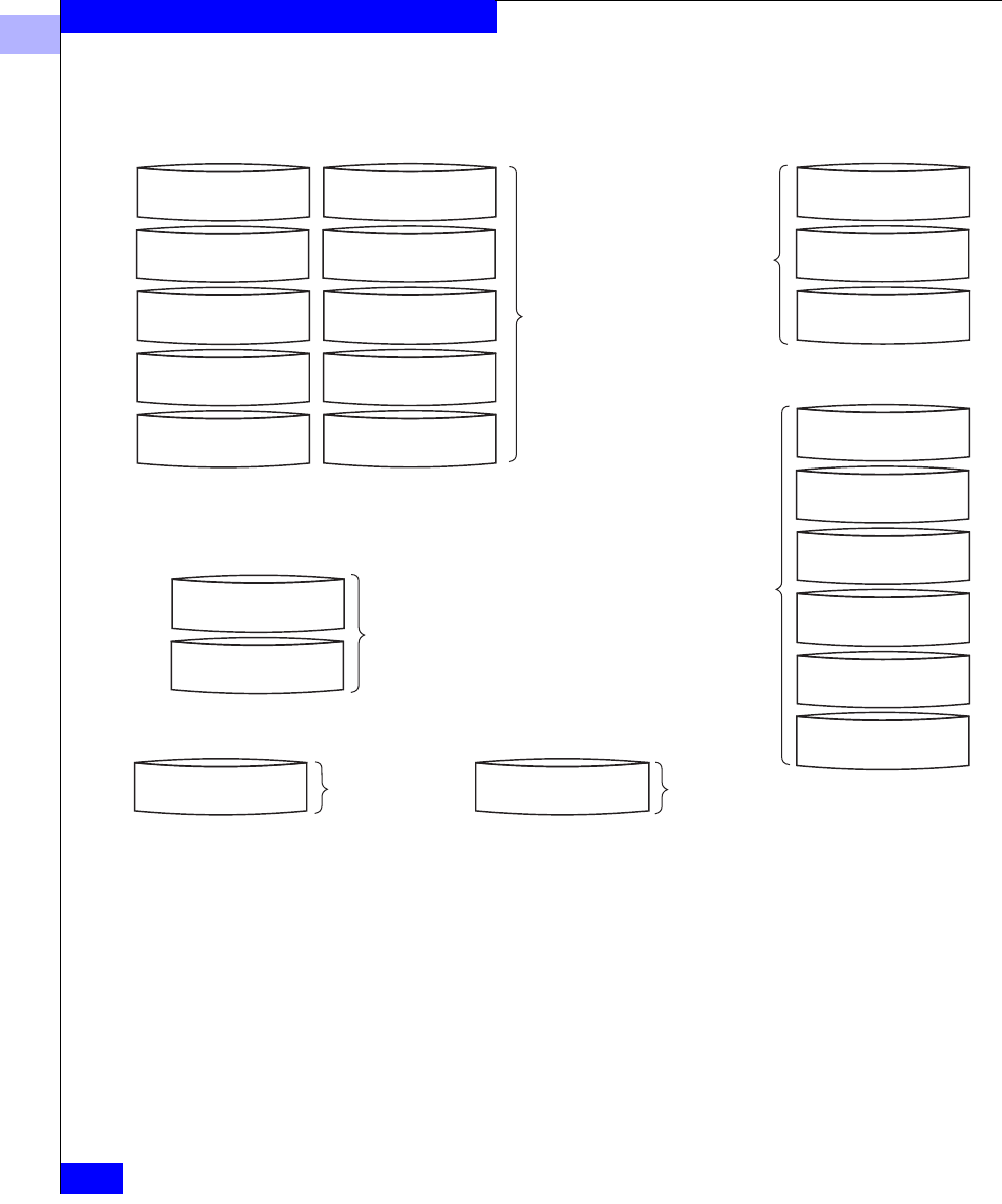
A RAID 1 mirrored pair or RAID 1/0 Group provides very high data
availability. They are more expensive than RAID 5 or RAID 3 Groups,
since only 50 percent of the total disk capacity is available for user
data, as shown on page 2-13.
A RAID 5 or RAID 3 Group provides high data availability, but
requires more disks than a mirrored pair. In a RAID 5 or RAID 3
Group of five disks, 80 percent of the disk space is available for user
data. So RAID 5 and RAID 3 Groups use disk space much more
efficiently than a mirrored pair. A RAID 5 or RAID 3 Group is usually
more suitable than a RAID 1 mirrored pair for applications where
high data availability, good performance, and efficient disk space
usage are all of relatively equal importance.
2
2-16
EMC Fibre Channel Storage-System Configuration Planning
RAID Types and Tradeoffs
Figure 2-7 Disk Space Usage in the RAID Configurations
A RAID 0 Group (nonredundant individual access array) provides all
its disk space for user files, but does not provide any high availability
features.
A RAID 1/0 Group provides the best combination of performance
and availability, at the highest cost per Mbyte of disk space.
An individual unit, like a RAID 0 Group, provides no
high-availability features. All its disk space is available for user data,
as shown in the figure above.
EMC1820
RAID 5 Group RAID 3 Group
2nd disk
user and parity data
2nd disk
user data
3rd disk
user and parity data
3rd disk
user data
4th disk
user and parity data
4th disk
user data
1st disk
user and parity data
1st disk
user data
5th disk
user and parity data
5th disk
parity data
80% user data
20% parity data
RAID 1/0 Group
2nd disk
user data
3rd disk
user data
4th disk
user data
6th disk
user data
1st disk
user data
5th disk
user data
50% user data
50% redundant data
RAID 0 Group
(nonredundant array)
2nd disk
user data
3rd disk
user data
1st disk
user data
100% user data
2nd disk
user data
1st disk
user data
Disk Mirror (RAID 1 mirrored pair)
50% user data
50% redundant data
User data
Individual Disk Unit
100% user dataReserved
Hot Spare
No user data

2
Guidelines for RAID Types
2-17
RAID Types and Tradeoffs
Guidelines for RAID Types
To decide when to use a RAID 5 Group, RAID 3 Group, mirror (that
is, a RAID 1 mirrored pair or RAID 1/0 Group), a RAID 0 Group,
individual disk unit, or hot spare, you need to weigh these factors:
•Importance of data availability
•Importance of performance
•Amount of data stored
•Cost of disk space
The following guidelines will help you decide on RAID types.
Use a RAID 5 Group (individual access array) for applications
where
•Data availability is very important
•Large volumes of data will be stored
•Multitask applications use I/O transfers of different sizes
•Good read and moderate write performance are important (write
caching can improve (RAID 5 write performance)
•You want the flexibility of multiple LUNs per RAID Group
Use a RAID 3 Group (parallel access array) for applications where
•Data availability is very important
•Large volumes of data will be stored
•A single-task application uses large I/O transfers (more than 64
Kbytes). The operating system must allow transfers aligned to
start at disk addresses that are multiples of 2 Kbytes from the start
of the LUN.
Use a RAID 1 mirrored pair for applications where
•Data availability is very important
•Speed of write access is important and write activity is heavy
Use a RAID 1/0 Group (mirrored nonredundant array) for
applications where
•Data availability is critically important
•Overall performance is very important

2
2-18
EMC Fibre Channel Storage-System Configuration Planning
RAID Types and Tradeoffs
Use a RAID 0 Group (nonredundant individual access array) for
applications where
•High availability is not important
•Overall performance is very important
Use an individual unit for applications where
•High availability is not important
•Speed of write access is somewhat important
Use a hot spare where
•In any RAID 5, RAID 3, RAID 1/0 or RAID 1 Group, high
availability is so important that you want to regain data
redundancy quickly without human intervention if any disk in
the Group fails
•Minimizing the degraded performance caused by disk failure in a
RAID 5 or RAID 3 Group is important

2
Sample Applications for RAID Types
2-19
RAID Types and Tradeoffs
Sample Applications for RAID Types
This section describes some types of applications in which you would
want to use a RAID 5 Group, RAID 3 Group, RAID 1 mirrored pair,
RAID 0 Group (nonredundant array), RAID 1/0 Group, or individual
unit.
RAID 5 Group (individual access array) — Useful as a database
repository or a database server that uses a normal or low percentage
of write operations (writes are 33 percent or less of all I/O
operations). Use a RAID 5 Group where multitask applications
perform I/O transfers of different sizes. Write caching can
significantly enhance the write performance of a RAID 5 Group.
For example, a RAID 5 Group is suitable for multitasking
applications that require a large history database with a high read
rate, such as a database of legal cases, medical records, or census
information. A RAID 5 Group also works well with transaction
processing applications, such as an airline reservations system, where
users typically read the information about several available flights
before making a reservation, which requires a write operation. You
could also use a RAID 5 Group in a retail environment, such as a
supermarket, to hold the price information accessed by the
point-of-sale terminals. Even though the price information may be
updated daily, requiring many write operations, it is read many more
times during the day.
RAID 3 Group — A RAID 3 Group (parallel access array) works well
with a single-task application that uses large I/O transfers (more than
64 Kbytes), aligned to start at a disk address that is a multiple of 2
Kbytes from the beginning of the logical disk. RAID 3 Groups can use
SP memory to great advantage without the second SP and battery
backup unit required for storage-system caching.
You might use a RAID 3 Group for a single-task application that does
large I/O transfers, like a weather tracking system, geologic charting
application, medical imaging system, or video storage application.
RAID 1 mirrored pair — A RAID 1 mirrored pair is useful for
logging or record-keeping applications because it requires fewer
disks than a RAID 0 Group (nonredundant array) and provides high
availability and fast write access. Or you could use it to store daily
updates to a database that resides on a RAID 5 Group, and then,
during off-peak hours, copy the updates to the database on the
RAID 5 Group.

2
2-20
EMC Fibre Channel Storage-System Configuration Planning
RAID Types and Tradeoffs
RAID 0 Group (nonredundant individual access array) — Use a
RAID 0 Group where the best overall performance is important. In
terms of high availability, a RAID 0 Group is less available than an
individual unit. A RAID 0 Group (like a RAID 5 Group) requires a
minimum of three disks. A RAID 0 Group serves well for an
application that uses short-term data to which users need quick
access.
RAID 1/0 Group (mirrored RAID 0 Group) — A RAID 1/0 Group
provides the best balance of performance and availability. You can
use it very effectively for any of the RAID 5 applications. A RAID 1/0
Group requires a minimum of four disks.
Individual unit — An individual unit is useful for print spooling,
user file exchange areas, or other such applications, where high
availability is not important or where the information stored is easily
restorable from backup.
The performance of an individual unit is slightly less than a standard
disk not in an storage system. The slight degradation results from SP
overhead.
Hot spare — A hot spare provides no data storage but enhances the
availability of each RAID 5, RAID 3, RAID 1, and RAID 1/0 Group in
a storage system. Use a hot spare where you must regain high
availability quickly without human intervention if any disk in such a
RAID Group fails. A hot spare also minimizes the period of degraded
performance after a RAID 5 or RAID 3 disk fails.
What Next? This chapter explained RAID Group types and tradeoffs. To plan
LUNs and file systems for shared storage, continue to Chapter 3; or
for unshared storage, skip to Chapter 4. For details on storage-
system hardware — shared and unshared — skip to Chapter 5.
For storage-system management utilities, skip to Chapter 6.

Planning File Systems and LUNs with Shared Switched Storage
3-1
3
This chapter shows a sample RAID, LUN, and Storage Group
configuration with shared storage, and then provides worksheets for
planning your own shared storage installation. Topics are
•Dual Paths to LUNs...........................................................................3-2
•Sample Shared Switched Installation..............................................3-3
•Planning Applications, LUNs, and Storage Groups.....................3-6
Planning File Systems
and LUNs with Shared
Switched Storage

3
3-2
EMC Fibre Channel Storage-System Configuration Planning
Planning File Systems and LUNs with Shared Switched Storage
Dual Paths to LUNs
A shared storage system includes two or more servers, one or two
Fibre Channel switches, and one or more storage systems, each with
two SPs and Access Logix software.
With shared storage, there are two paths to each LUN in the storage
system. The storage-system software, using optional software called
Application Transparent Failover (ATF), can automatically switch to
the other path if a device (such as a host-bus adapter or cable) fails.
With unshared storage, if the server has two adapters and the storage
system has two SPs, ATF software is available as an option. With two
adapters and two SPs, ATF can perform the same function as with
shared systems: automatically switch to the other path if a device
(such as host bus adapter or cable) fails.
3
Sample Shared Switched Installation
3-3
Planning File Systems and LUNs with Shared Switched Storage
Sample Shared Switched Installation
The following figure shows a sample shared switched
(high-availability) storage system connected to three servers: two
servers in a cluster and one server running a database management
program.
Figure 3-1 Sample Shared Switched High Availability installation
SP B
SP A
Cluster
Storage Group
Database Server
Storage Group
File Server (FS) Mail Server(MS) Database Server(DS)
Switch fabric
Adapter
Adapter
Operating
system A
Adapter
Adapter
Operating
system A
Adapter
Adapter
Operating
system B
1_0-1_9
2_0-2_9
0_0-0_9
3_0-3_9
4_0-4_9
Path 2
Path 1
MS R5
ISP B mail
MS R5
ISP A mail
DS R5 (6
disks) Dbase1
DS R1
LogD1
FS R5
Files A FS R5
Files B
DS R5
Dbase2
DS R5
Users
MS R5
Users MS R5
Specs
Private storage
Highly available cluster
Disk IDs
Switch fabric
Spare
Spare

3
3-4
EMC Fibre Channel Storage-System Configuration Planning
Planning File Systems and LUNs with Shared Switched Storage
The storage-system disk IDs and server Storage Group LUNs are as
follows.
With 36-Megabyte disks, the LUN storage capacities and drive names
are as follows.
File Server — 288 Gbytes on two LUNs
Unit U on five disks bound as a RAID 5 Group for
144 Gbytes of storage; for file storage.
Unit V on five disks bound as a RAID 5 Group for
144 Gbytes of storage; for file storage.
Clustered System LUNs Database Server LUNs (DS) - SP A
File Server LUNs (FS) - SP B Mail Server LUNs (MS) - SP A
Disk IDs RAID type, storage type
4_0-4_4 RAID 5, Files A
4_5-4_9 RAID 5, Files B
Disk IDs RAID type, storage type
2_0-2_4 RAID 5, ISP A mail
2_5-2_9 RAID 5, ISP B mail
3_0-3_4 RAID 5, Users
3_5-3_9 RAID 5, Specs
Disk IDs RAID type, storage type
0_0, 0_ 1 RAID 1, Log file for
database Dbase1
0_4-0_9 RAID 5 (6 disks), Dbase1
1_0-1_4 RAID 5, Users
1_5-1_9 RAID 5, Dbase2
6_0, 6_1 – Hot spare (automatically replaces a failed disk in any server’s LUN)
FS R5
FilesA
FS R5
FilesB

3
Sample Shared Switched Installation
3-5
Planning File Systems and LUNs with Shared Switched Storage
Mail Server — 576 Gbytes on four LUNs
Unit O on five disks bound as a RAID 5 Group for
144 Gbytes of storage; for the mail delivered via ISP A.
Unit P on five disks bound as a RAID 5 Group for
144 Gbytes of storage; for the mail delivered via ISP B.
Unit Q on five disks bound as a RAID 5 Group for
144 Gbytes of storage; for user directories and files.
Unit R on five disks bound as a RAID 5 Group for
144 Gbytes of storage; for specifications.
Database Server — 416 Gbytes on four LUNs
Unit users on five disks bound as a RAID 5 Group for
144 Gbytes of storage; for user directories.
Unit dbase2 on five disks bound as a RAID 5 Group
for 144 Gbytes of storage; for the second database system.
Unit logfiles on two disks bound as a RAID 1 mirrored
pair for 36 Gbytes of storage; for the database log files.
Unit dbase on six disks bound as a RAID 5 Group for
180 Gbytes of storage; for the primary database system.
MS R5
ISP mail
MS R5
ISP mail
MSR5
Users
MS R5
Specs
DS R5
Users
DS R5
Dbase2
DS R1
Logs
DS R5
Dbase1

3
3-6
EMC Fibre Channel Storage-System Configuration Planning
Planning File Systems and LUNs with Shared Switched Storage
Planning Applications, LUNs, and Storage Groups
This section helps you plan your shared storage use — the
applications to run, the LUNs that will hold them, and the Storage
Groups that will belong to each server. The worksheets to help you
do this include
•Application and LUN planning worksheet - lets you outline your
storage needs.
•LUN and Storage Group planning worksheet - lets you decide on
the disks to compose the LUNs and the LUNs to compose the
Storage Groups for each server.
•LUN details worksheet - lets you plan each LUN in detail.
Make as many copies of each blank worksheet as you need. You will
need this information later when you configure the shared storage
system.
Sample worksheets appear later in this chapter.
Application and LUN Planning
Use the following worksheet to list the applications you will run and
the RAID type and size of LUN to hold them. For each application
that will run in the SAN, write the application name, file system (if
any), RAID type, LUN ID (ascending integers, starting with 0), disk
space required, and finally the name of the servers and operating
systems that will use the LUN.
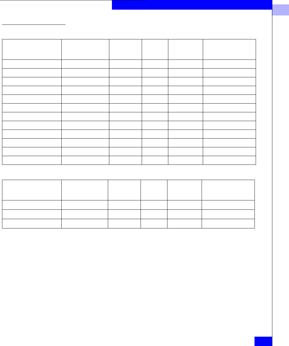
3
Planning Applications, LUNs, and Storage Groups
3-7
Planning File Systems and LUNs with Shared Switched Storage
Application and LUN Planning Worksheet
A sample worksheet begins as follows:
Completing the Application and LUN Planning Worksheet
Application. Enter the application name or type.
File system, partition, or drive. Write the drive letter (for Windows
only) and the partition, file system, logical volume, or drive letter
name, if any.
With a Windows operating system, the LUNs are identified by drive
letter only. The letter does not help you identify the disk
configuration (such as RAID 5). We suggest that later, when you use
the operating system to create a partition on a LUN, you use the disk
administrator software to assign a volume label that describes the
RAID configuration. For example, for drive T, assign the volume ID
RAID5_T. The volume label will then identify the drive letter.
Application
File system,
partition, or drive
RAID type of
LUN
LUN
ID (hex)
Disk space
required
(Gbytes)
Server name and
operating system
Application
File system,
partition, or drive
RAID type of
LUN
LUN
ID (hex)
Disk space
required
(Gbytes)
Server name and
operating system
M
a
il 1 R
A
ID 5 0
72
G
b
S
e
r
ver
1, NT
M
a
il 2 R
A
ID 5 1
72
G
b
S
e
r
ver
1, NT
Database index R
A
I
D 1 2
1
8
G
b
S
e
r
ver
2, NT

3
3-8
EMC Fibre Channel Storage-System Configuration Planning
Planning File Systems and LUNs with Shared Switched Storage
RAID type of LUN. This is the RAID Group type you want for this
partition, file system, or logical volume. The features of RAID types
are explained in Chapter 2. For a RAID 5, RAID 1, RAID 1/0, and
RAID 0 Group, you can create one or more LUNs on the RAID
Group. For other RAID types, you can create only one LUN per RAID
Group.
LUN ID. The LUN ID is a hexadecimal number assigned when you
bind the disks into a LUN. By default, the ID of the first LUN bound
is 0, the second 1, and so on. Each LUN ID must be unique within the
storage system, regardless of its Storage Group or RAID Group.
The maximum number of LUNs supported on one host-bus adapter
depends on the operating system.
Disk space required (Gbytes). Consider the largest amount of disk
space this application will need, then add a factor for growth.
Server hostname and operating system. Enter the server hostname
(or, if you don’t know the name, a short description that identifies the
server) and the operating system name, if you know it.
LUN and Storage Group Planning Worksheet
Use the following worksheet to select the disks that will make up the
LUNs and Storage Groups in the SAN. A shared storage system can
include up to 100 disks, numbered 0 through 99, left to right from the
bottom up.
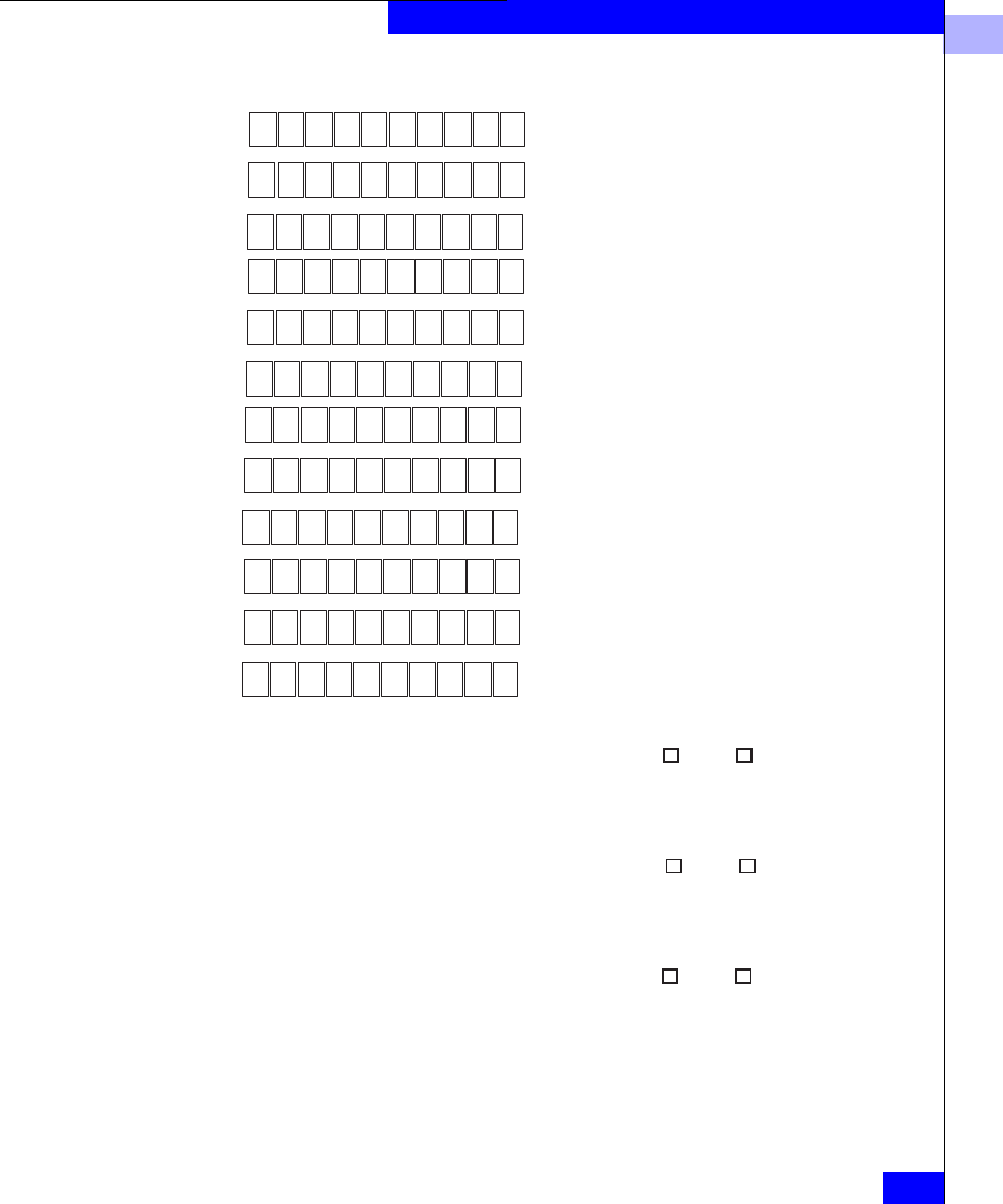
3
Planning Applications, LUNs, and Storage Groups
3-9
Planning File Systems and LUNs with Shared Switched Storage
LUN and Storage Group Planning Worksheet
Storage Group ID or name:______ Server hostname:_____________________ Dedicated Shared
LUN ID or name_______RAID type ___ Cap. (Gb) _____ Disk IDs_________________________________________
LUN ID or name_______RAID type ___ Cap. (Gb) _____ Disk IDs_________________________________________
LUN ID or name_______RAID type ___ Cap. (Gb) _____ Disk IDs_________________________________________
LUN ID or name_______RAID type ___ Cap. (Gb) _____ Disk IDs_________________________________________
0_0 0_1 0_2 0_3 0_4 0_5 0_6 0_7 0_8 0_9
1_0 1_1 1_2 1_3 1_4 1_5 1_6 1_7 1_8 1_9
2_0 2_1 2_2 2_3 2_4 2_5 2_6 2_7 2_8 2_9
3_0 3_1 3_2 3_3 3_4 3_5 3_6 3_7 3_8 3_9
4_0 4_1 4_2 4_3 4_4 4_5 4_6 4_7 4_8 4_9
5_0 5_1 5_2 5_3 5_4 5_5 5_6 5_7 5_8 5_9
6_0 6_1 6_2 6_3 6_4 6_5 6_6 6_7 6_8 6_9
7_0 7_1 7_2 7_3 7_4 7_5 7_6 7_7 7_8 7_9
8_0 8_1 8_2 8_3 8_4 8_5 8_6 8_7 8_8 9_9
9_0 9_1 9_2 9_3 9_4 9_5 9_6 9_7 9_8 9_9
10_0 10_1 10_210_3 10_4 10_5 10_610_7 10_8 10_9
11_0 11_1 11_211_3 11_4 11_511_6 11_7 11_811_9
Storage system number or name:_______________
Storage Group ID or name:______ Server hostname:_____________________ Dedicated Shared
LUN ID or name_______RAID type ___ Cap. (Gb) _____ Disk IDs_________________________________________
LUN ID or name_______RAID type ___ Cap. (Gb) _____ Disk IDs_________________________________________
LUN ID or name_______RAID type ___ Cap. (Gb) _____ Disk IDs_________________________________________
LUN ID or name_______RAID type ___ Cap. (Gb) _____ Disk IDs_________________________________________
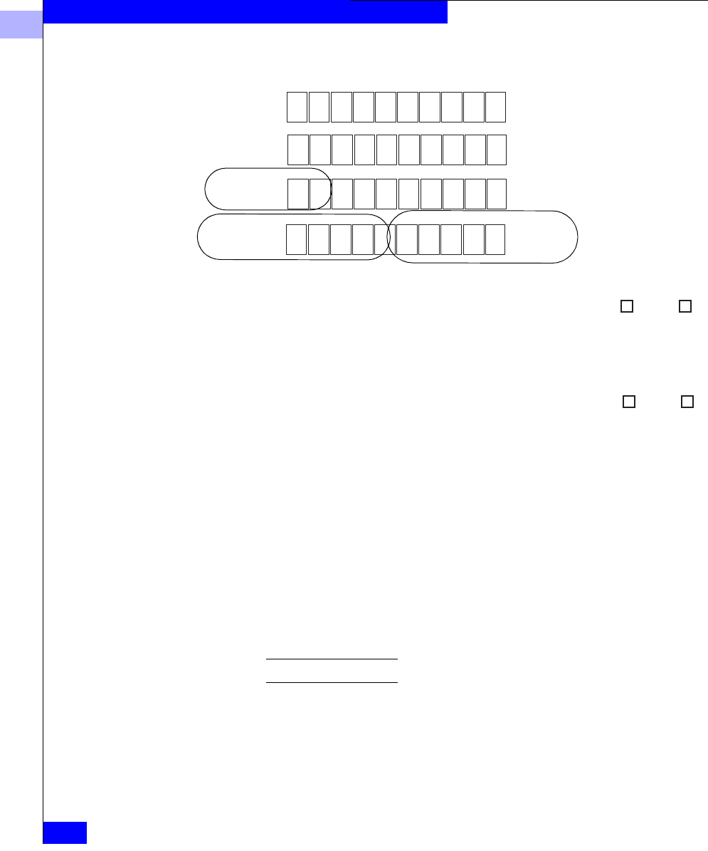
3
3-10
EMC Fibre Channel Storage-System Configuration Planning
Planning File Systems and LUNs with Shared Switched Storage
Part of a sample LUN and Storage Group worksheet follows.
Completing the LUN and Storage Group Planning Worksheet
As shown, draw circles around the disks that will compose each
LUN, and within each circle specify the RAID type (for example,
RAID 5) and LUN ID. This is information you will use to bind the
disks into LUNs. For disk IDs, use the form shown. This form is
enclosure_diskID, where enclosure is the enclosure number (the bottom
one is 0, above it 1, and so on) and diskID is the disk position (left is 0,
next is 1, and so on).
None of the disks 0_0 through 0_8 may be used as a hot spare.
Next, complete as many of the Storage System sections as needed for
all the Storage Groups in the SAN. Copy the (blank) worksheet as
needed for all Storage Groups in each storage system.
A storage system is any group of enclosures connected to a DPE; it
can include up to 11 DAE enclosures for a total of 120 disks. If a
Storage Group ID or name:______ Server hostname:_____________________ Dedicated Shared
LUN ID or name_______RAID type ___ Cap. (Gb) _____ Disk IDs_____________________________
_
LUN ID or name_______RAID type ___ Cap. (Gb) _____ Disk IDs_____________________________
_
LUN ID or name_______RAID type ___ Cap. (Gb) _____ Disk IDs_____________________________
_
LUN ID or name_______RAID type ___ Cap. (Gb) _____ Disk IDs_____________________________
_
0_0 0_1 0_2 0_3 0_4 0_5 0_6 0_7 0_8 0_9
1_0 1_1 1_2 1_3 1_4 1_5 1_6 1_7 1_8 1_9
2_0 2_1 2_2 2_3 2_4 2_5 2_6 2_7 2_8 2_9
3_0 3_1 3_2 3_3 3_4 3_5 3_6 3_7 3_8 3_9
Storage system number or name:_______________
Storage Group ID or name:______ Server hostname:_____________________ Dedicated Shared
LUN ID or name_______RAID type ___ Cap. (Gb) _____ Disk IDs_____________________________
_
LUN ID or name_______RAID type ___ Cap. (Gb) _____ Disk IDs_____________________________
_
LUN ID or name_______RAID type ___ Cap. (Gb) _____ Disk IDs_____________________________
_
LUN ID or name_______RAID type ___ Cap. (Gb) _____ Disk IDs_____________________________
_
LUN 0
RAID 5
LUN 1
RAID 5
LUN 2
RAID 1
Server1
X
1
2
0
Server2
X
Mail 1
0_0, 0_1, 0_2, 0_3, 0_4
5
72
1
Index1
0_5, 0_6, 0_7, 0_8, 0_9
1_0, 1_1
72
5
SS1
18

3
Planning Applications, LUNs, and Storage Groups
3-11
Planning File Systems and LUNs with Shared Switched Storage
Storage Group will be dedicated (not accessible by another system in
a cluster), mark the Dedicated box at the end of its line; if the Storage
Group will be accessible to one or more other servers in a cluster,
write the hostnames of all servers and mark the Shared box.
LUN Details Worksheet
Use the following LUN details worksheet to plan the individual
LUNs. Complete as many of these as needed for all LUNs in your
SAN.

3
3-12
EMC Fibre Channel Storage-System Configuration Planning
Planning File Systems and LUNs with Shared Switched Storage
LUN Details Worksheet
Storage system (complete this section once for each storage system)
Storage-system number or name:______
Storage-system installation type
❏Unshared Direct ❏Shared-or-Clustered Direct ❏Shared Switched
SP FC-AL address ID (unshared only): SP A:_____SP B:_____
SP memory (Mbytes): SP A:___ SP B:____
❏Use for caching Read cache size:__ MB Write cache size: __ MB Cache page size:___KB
❏Use for RAID 3
LUN ID:_____
RAID Group ID: Size,GB: LUN size,GB: Disk IDs: SP: ❏A❏B
RAID type: ❏RAID 5 ❏RAID 3 - Memory, MB:___ ❏RAID 1 mirrored pair ❏RAID 0
❏RAID 1/0 ❏Individual disk ❏Hot spare
Caching: ❏Read and write ❏Write ❏Read ❏None
Servers that can access this LUN:
Operating system information: Device name: File system, partition, or drive:
LUN ID:____
RAID Group ID: Size,GB: LUN size,GB: Disk IDs: SP: ❏A❏B
RAID type: ❏RAID 5 ❏RAID 3 - Memory, MB:___ ❏RAID 1 mirrored pair ❏RAID 0
❏RAID 1/0 ❏Individual disk ❏Hot spare
Caching: ❏Read and write ❏Write ❏Read ❏None
Servers that can access this LUN:
Operating system information: Device name: File system, partition, or drive:

3
Planning Applications, LUNs, and Storage Groups
3-13
Planning File Systems and LUNs with Shared Switched Storage
LUN Details Worksheet
Storage system (complete this section once for each storage system)
Storage-system number or name:__SS1____
Storage-system installation type
❏Unshared Direct ❏Shared-or-Clustered Direct ❏Shared Switched
SP FC-AL address ID (unshared only): SP A:_____SP B:_____
SP memory (Mbytes): SP A:_256__ SP B:_256__
❏Use for caching Read cache size:_80_ MB Write cache size: _160_ MB Cache page size:_2__KB
❏Use for RAID 3
LUN ID:__0___
RAID Group ID: 0Size,GB: 72 LUN size,GB: 72 Disk IDs: SP: ❏A❏B
RAID type: ❏RAID 5 ❏RAID 3 - Memory, MB:___ ❏RAID 1 mirrored pair ❏RAID 0
❏RAID 1/0 ❏Individual disk ❏Hot spare
Caching: ❏Read and write ❏Write ❏Read ❏None
Servers that can access this LUN: Server1
Operating system information: Device name: File system, partition, or drive: T
LUN ID:__1__
RAID Group ID: 1 Size,GB: 72 LUN size,GB: 72 Disk IDs: SP: ❏A❏B
RAID type: ❏RAID 5 ❏RAID 3 - Memory, MB:___ ❏RAID 1 mirrored pair ❏RAID 0
❏RAID 1/0 ❏Individual disk ❏Hot spare
Caching: ❏Read and write ❏Write ❏Read ❏None
Servers that can access this LUN: Server1
Operating system information: Device name: File system, partition, or drive: U
LUN ID:__2__
RAID Group ID: 2Size,GB: LUN size,GB: 18 Disk IDs: SP: ❏A❏B
RAID type: ❏RAID 5 ❏RAID 3 - Memory, MB:___ ❏RAID 1 mirrored pair ❏RAID 0
❏RAID 1/0 ❏Individual disk ❏Hot spare
Caching: ❏Read and write ❏Write ❏Read ❏None
Servers that can access this LUN: Server1
Operating system information: Device name: File system, partition, or drive: V
X
0_0,0_1,0_2,0_3,0_4
18
X
X
X
X
1_0, 1_1
X
X
X
X
X
0_5, 0_6, 0_7, 0_8, 0_9

3
3-14
EMC Fibre Channel Storage-System Configuration Planning
Planning File Systems and LUNs with Shared Switched Storage
Completing the LUN Details Worksheet
Complete the header portion of the worksheet for each storage
system as described below. Copy the blank worksheet as needed.
Storage-system entries
Storage-system installation type, specify Shared Switched
storage.
SP FC-AL address ID. This does not apply to shared storage, in
which the switch determines the address of each device.
Use memory for caching. You can use SP memory for read/write
caching or RAID 3. (Using both caching and RAID 3 in the same
storage system is not recommended.) You can use different cache
settings for different times of day (for example, for user I/O
during the day, use more write cache; for sequential batch jobs at
night, use more read cache. You enable caching for specific LUNs
— allowing you to tailor your cache resources according to
priority. If you choose caching, check the box and continue to the
next step; for RAID 3, skip to the RAID Group ID entry.
Read cache size. If you want a read cache, it should generally be
about one third of the total available cache memory.
Write cache size. The write cache should be two thirds of the total
available. Some memory is required for system overhead, so you
cannot determine a precise figure at this time. For example, for
256 Mbytes of total memory, you might have 240 Mbytes
available, and you would specify 80 Mbytes for the read cache
and 160 Mbytes for the write cache.
Cache page size. This applies to both read and write caches. It can
be 2, 4, 8, or 16 Kbytes. As a general guideline, we suggest
•For a general-purpose file server — 8 Kbytes
•For a database application — 2 or 4 Kbytes
The ideal cache page size depends on the operating system and
application.
Use memory for RAID 3. If you want to use the SP memory for
RAID 3, check the box.
RAID Group/LUN Entries
Complete a RAID Group/LUN entry for each LUN and hot spare.

3
Planning Applications, LUNs, and Storage Groups
3-15
Planning File Systems and LUNs with Shared Switched Storage
LUN ID. The LUN ID is a hexadecimal number assigned when
you bind the disks into a LUN. By default, the ID of the first LUN
bound is 0, the second 1, and so on. Each LUN ID must be unique
within the storage system, regardless of its Storage Group or
RAID Group.
The maximum number of LUNs supported on one host-bus
adapter depends on the operating system.
RAID Group ID. This ID is a hexadecimal number assigned
when you create the RAID Group. By default, the number of the
first RAID Group in a storage system is 0, the second 1, and so on,
up to the maximum of 1F (31).
Size (RAID Group size). Enter the user-available capacity in
gigabytes (Gbytes) of the whole RAID Group. You can determine
the capacity as follows:
For example,
•A five-disk RAID 5 or RAID 3 Group of 36-Gbyte disks holds
144 Gbytes;
•An eight-disk RAID 1/0 Group of 36-Gbyte disks also holds
144 Gbytes;
•A RAID 1 mirrored pair of 36-Gbyte disks holds 36 Gbytes;
and
•An individual disk of an 36-Gbyte disk also holds 36 Gbytes.
Each disk in the RAID Group must have the same capacity;
otherwise, you will waste disk storage space.
LUN size. Enter the user-available capacity in gigabytes (Gbytes)
of the LUN. You can make this the same size as the RAID Group,
above. Or, for a RAID 5, RAID 1, RAID 1/0, or RAID 0 Group,
you can make the LUN smaller than the RAID Group. You might
do this if you wanted a RAID 5 Group with a large capacity and
wanted to place many smaller capacity LUNs on it; for example,
to specify a LUN for each user. However, having multiple LUNs
RAID5 or RAID-3 Group: disk-size * (number-of-disks - 1)
RAID 1/0 or RAID-1 Group: (disk-size * number-of-disks) / 2
RAID 0 Group: disk-size * number-of-disks
Individual unit: disk-size

3
3-16
EMC Fibre Channel Storage-System Configuration Planning
Planning File Systems and LUNs with Shared Switched Storage
per RAID Group may adversely impact performance. If you want
multiple LUNs per RAID Group, then use a RAID Group/LUN
series of entries for each LUN.
Disk IDs. Enter the ID(s) of all disks that will make up the LUN
or hot spare. These are the same disk IDs you specified on the
previous worksheet. For example, for a RAID 5 Group in the DPE
(enclosure 0, disks 2 through 6), enter 0_2, 0_3, 0_4, 0_5, and 0_6.
SP. Specify the SP that will own the LUN: SP A or SP B. You can
let the management program automatically select the SP to
balance the workload between SPs; to do so, leave this entry
blank.
RAID type. Copy the RAID type from the previous worksheet.
For example, RAID 5 or hot spare. For a hot spare (not strictly
speaking a LUN at all), skip the rest of this LUN entry and
continue to the next LUN entry (if any).
If this is a RAID 3 Group, specify the amount of SP memory for
that group. To work efficiently, each RAID 3 Group needs at least
6 Mbytes of memory.
Caching. If you want to use caching (entry on page 3-14), you can
specify whether you want caching — read and write, read, or
write for this LUN. Generally, write caching improves
performance far more than read caching. The ability to specify
caching on a LUN basis provides additional flexibility, since you
can use caching for only the units that will benefit from it. Read
and write caching recommendations follow.
Table 3-1 Cache Recommendations for Different RAID Types
Servers that can access this LUN. Enter the name of each server
(copied from the LUN and Storage Group worksheet).
Operating system information: Device name. Enter the
operating system device name, if this is important and if you
know it. Depending on your operating system, you may not be
able to complete this field now.
RAID 5 RAID 3 RAID 1 RAID 1/0 RAID 0 Individual Unit
Highly Recommended Not allowed Recommended Recommended Recommended Recommended

3
Planning Applications, LUNs, and Storage Groups
3-17
Planning File Systems and LUNs with Shared Switched Storage
File system, partition, or drive. Write the name of the file system,
partition, or drive letter you will create on this LUN. This is the
same name you wrote on the application worksheet.
On the following line, write any pertinent notes; for example, the
file system mount- or graft-point directory pathname (from the
root directory). If this storage system’s chassis will be shared with
another server, and the other server is the primary owner of this
disk, write secondary. (As mentioned earlier, if the storage system
will be used by two servers, we suggest you complete one of
these worksheets for each server.)
What Next? This chapter outlined the planning tasks for shared storage systems.
If you have completed the worksheets to your satisfaction, you are
ready to learn about the hardware needed for these systems as
explained in Chapter 5.

3
3-18
EMC Fibre Channel Storage-System Configuration Planning
Planning File Systems and LUNs with Shared Switched Storage

Planning LUNs and File Systems with Unshared Direct Storage
4-1
4
Invisible Body Tag
This chapter shows sample RAID and LUN configurations with
direct storage installations and then provides worksheets for
planning your own storage installation. Topics are
•Dual SPs and Paths to LUNs............................................................4-2
•Unshared Direct and Shared-or-Clustered Direct Storage...........4-2
•Planning Applications and LUNs ...................................................4-4
Planning LUNs and File
Systems with Unshared
Direct Storage
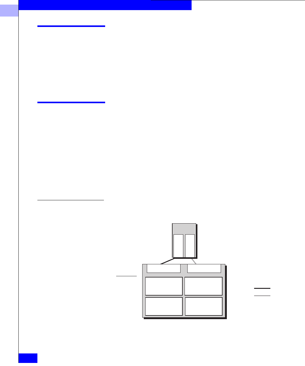
4
4-2
EMC Fibre Channel Storage Systems Configuration Planning Guide
Planning LUNs and File Systems with Unshared Direct Storage
Dual SPs and Paths to LUNs
If a storage system has two SPs, there are two routes to its LUNs. If
the server has two adapters and the storage system has two SPs,
Application Transparent Failover (ATF). ATF can automatically
switch to the other path, without disrupting applications, if a device
(such as a host-bus adapter, cable, or SP) fails.
Unshared Direct and Shared-or-Clustered Direct Storage
This section explains the direct (unswitched) options available for
connecting storage systems to servers. As needs change, you may
want to change a configuration. You can do so without changing your
LUN configuration or losing user data.
There are two types of installation:
•Unshared direct with one server is the simplest and least costly;
•Shared-or-clustered direct lets two clustered servers share
storage resources with high availability.
Sample Unshared Direct Installation
Figure 4-1 Unshared Direct Installation
EMC1825
Disk IDs
100-109
010-019
Database
RAID 5 Users
RAID 5
Sys
RAID 1
Clients, mail
RAID 5
SP A SP B
Adapter
Adapter
Server
Path 1
Path 2
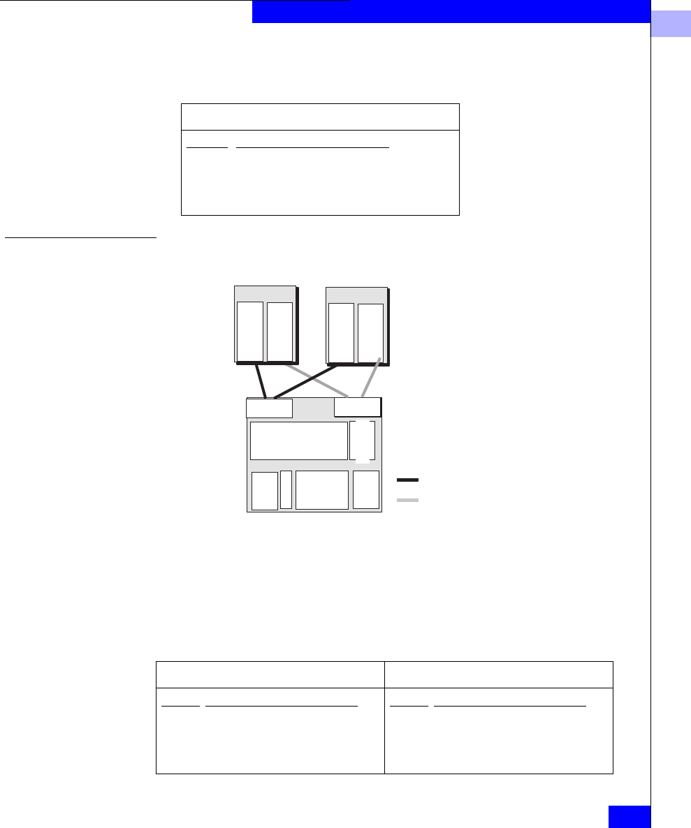
4
Unshared Direct and Shared-or-Clustered Direct Storage
4-3
Planning LUNs and File Systems with Unshared Direct Storage
The storage system disk IDs and LUNs are as follows. The LUN
capacities shown assume 36-Gbyte disks.
Sample Shared-or-Clustered Direct Installation
Figure 4-2 Sample Clustered Installation
If each disk holds 36 Gbytes, then the storage-system chassis provides
Server 1 with 256 Gbytes of disk storage, 220 Gbytes highly available;
it provides Server 2 with 216 Gbytes of storage, all highly available.
Each server has its own SP, which controls that server’s LUNs; those
LUNs remain primary to that server. The LUNs are as follows.
LUNs - SP A and SP B, 422 Gbytes
Disk IDs RAID type, storage type, capacity
0_0, 0_1 RAID 1, System disk, 36 Gbytes
0_2-0_9 RAID 5 (8 disks), Clients and Mail, 216 Gbytes
1_0-1_4 RAID 5, Database, 144 Gbytes
1_5 Disk, Temporary storage, 36 Gbytes
Path 2
Path 1
Server 2 (S2)
Server 1 (S1)
Storage
system
S1Mail
RAID1
S2 Customers
RAID 5
S1Dbase
RAID 5
Unused
Spare
S2 Usri
RAID1
SP A SP B
Adapter
Adapter
Adapter
Adapter
Server1 LUNs (S1) - SP A, 256 Gbytes Server2 LUNs (S2) - SP B, 216 Gbytes
Disk IDs RAID type, storage type, capacity
0_0, 0_1 RAID 1, System disk, 36 Gbytes
0_2 Disk, Temporary storage, 36 Gbytes
0_3-0_7 RAID 5, Database, 144 Gbytes
0_8-0_ 9 RAID 1, Users, 36 Gbytes
Disk IDs RAID type, storage type, capacity
1_0-1_7 RAID 5 (8 disks), Cust Accounts, 216
Gbytes

4
4-4
EMC Fibre Channel Storage Systems Configuration Planning Guide
Planning LUNs and File Systems with Unshared Direct Storage
Planning Applications and LUNs
This section helps you plan your unshared (direct) storage use —
applications you want to run and the LUNs that will hold them. The
worksheets to help you do this include
•Application and file system planning worksheet - lets you outline
your storage needs.
•LUN planning worksheet - lets you decide on the disks that will
compose the LUNs.
•LUN details worksheet - lets you plan each LUN in detail.
Make as many copies of each blank worksheet as you need. You will
need this information later when you configure the shared storage
system.
Sample file system, Storage Group, and LUN worksheets appear later
in this chapter.
Application and LUN Planning
Use the following worksheet to plan your file systems and RAID
types. For each application, write the application name, file system (if
any), RAID type, LUN ID (ascending integers, starting with 0), disk
space required, and finally the name of the servers and operating
systems that will use the LUN.
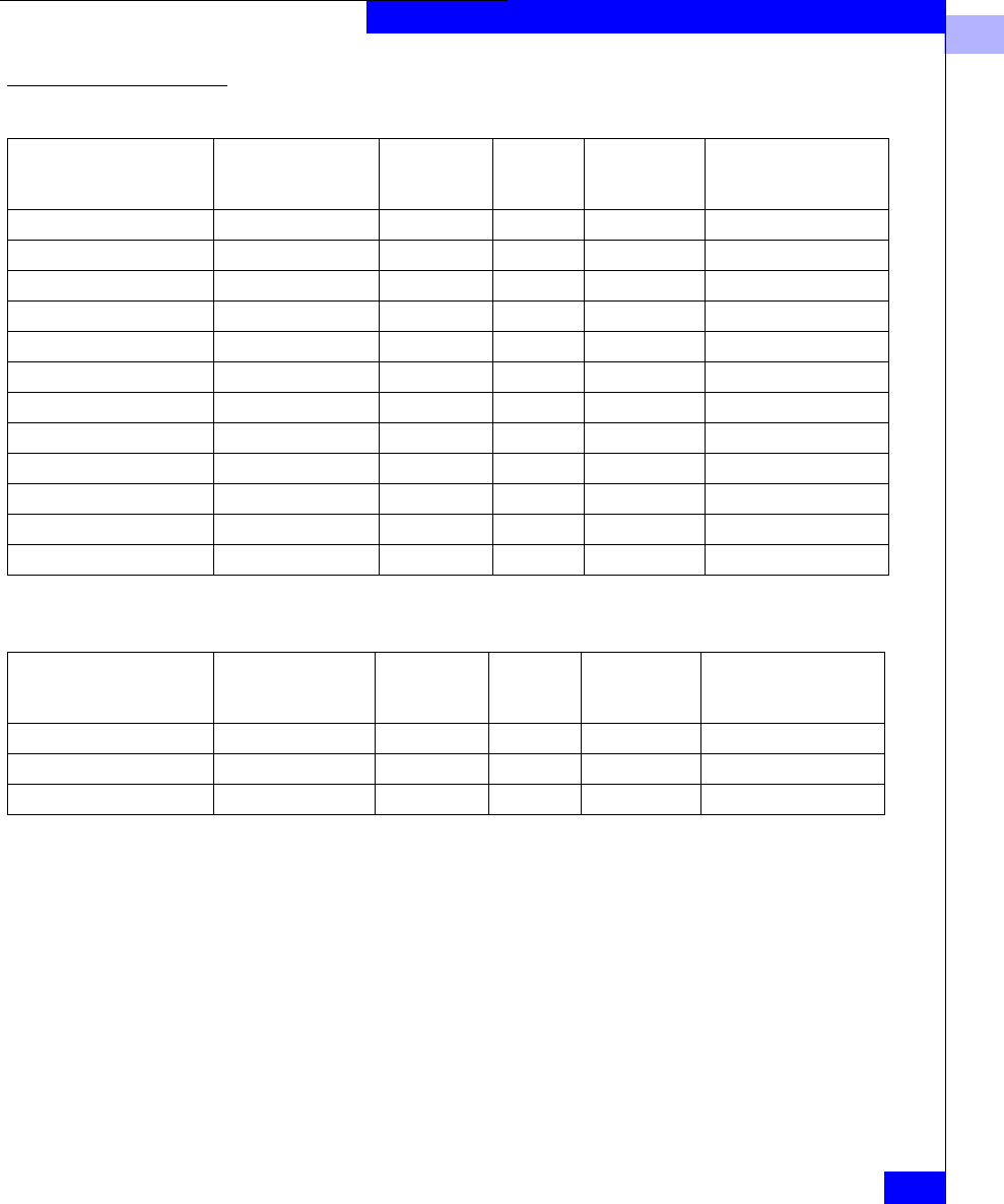
4
Planning Applications and LUNs
4-5
Planning LUNs and File Systems with Unshared Direct Storage
Application and LUN Planning Worksheet
A sample worksheet begins as follows:
Completing the Application and LUN Planning Worksheet
Application. Enter the application name or type.
File system, partition, or drive. Write the drive letter (for Windows
only) and the partition, file system, logical volume, or drive letter
(Windows only) name.
With a system such as Windows NT, the LUNs are identified by drive
letter only. The letter does not help you identify the disk
configuration (such as RAID 5). We suggest that later, when you use
the operating system to create a partition on the unit, you use the disk
administrator software to assign a volume label that describes the
Application File system (if any)
RAID type of
LUN
LUN
ID (hex)
Disk space
required
(Gbytes)
Server name and
operating system
Application File system (if any)
RAID type of
LUN
LUN
ID (hex)
Disk space
required
(Gbytes)
Server name and
operating system
M
a
il 1 R
A
I D 5 0
72
G
b
S
e
r
ver
1, NT
M
a
il 2 R
A
I D 5 1
72
G
b
S
e
r
ver
1, NT
Database index R
A
I
D 1 2
1
8
G
b
S
e
r
ver
2, NT

4
4-6
EMC Fibre Channel Storage Systems Configuration Planning Guide
Planning LUNs and File Systems with Unshared Direct Storage
RAID configuration. For example, for drive T, assign the volume ID
RAID5_T. The volume label will then identify the drive letter.
RAID type of LUN is the RAID Group type you want for this
partition, file system, or logical volume. The features of RAID types
are explained in Chapter 2. For a RAID 5, RAID 1, RAID 1/0, and
RAID 0 Group, you can create one or more LUNs on the RAID
Group. For other RAID types, you can create only one LUN per RAID
Group.
LUN ID is a hexadecimal number assigned when you bind the disks
into a LUN. By default, the ID of the first LUN bound is 0, the second
1, and so on. Each LUN ID must be unique within the storage system,
regardless of its Storage Group or RAID Group.
The maximum number of LUNs supported on one host-bus adapter
depends on the operating system. Some systems allow only eight
LUNs (numbers 0 through 7). For an operating system with this
restriction, if you want a hot spare, assign the hot spare an ID above
7; for example, 8 or 9. The operating system never accesses a hot
spare, so the ID is irrelevant to it.
Disk space required (Gbytes), Consider the largest amount of disk
space this application will need, then add a factor for growth.
Server hostname and operating system Enter the server hostname
(or, if you don’t know the name, a short description that identifies the
server) and the operating system name, if you know it.
If this storage system will be used by two servers, provide a copy of
this worksheet to the other server. This is particularly important
where one server may take over the other’s LUNs. If a LUN will be
shared, on the Notes section of the LUN details worksheet, write
Primary to server-name or Secondary to server-name.
LUN Planning Worksheet
Use one of the following worksheets (Rackmount or Deskside) to
select the disks that will make up the LUNs. Depending on model, a
full-fibre rackmount storage system can include up to 100 disks,
numbered 0 through 99, left to right from the bottom up.
Again depending on model, a deskside storage system can hold ten,
20, or 30 disks.
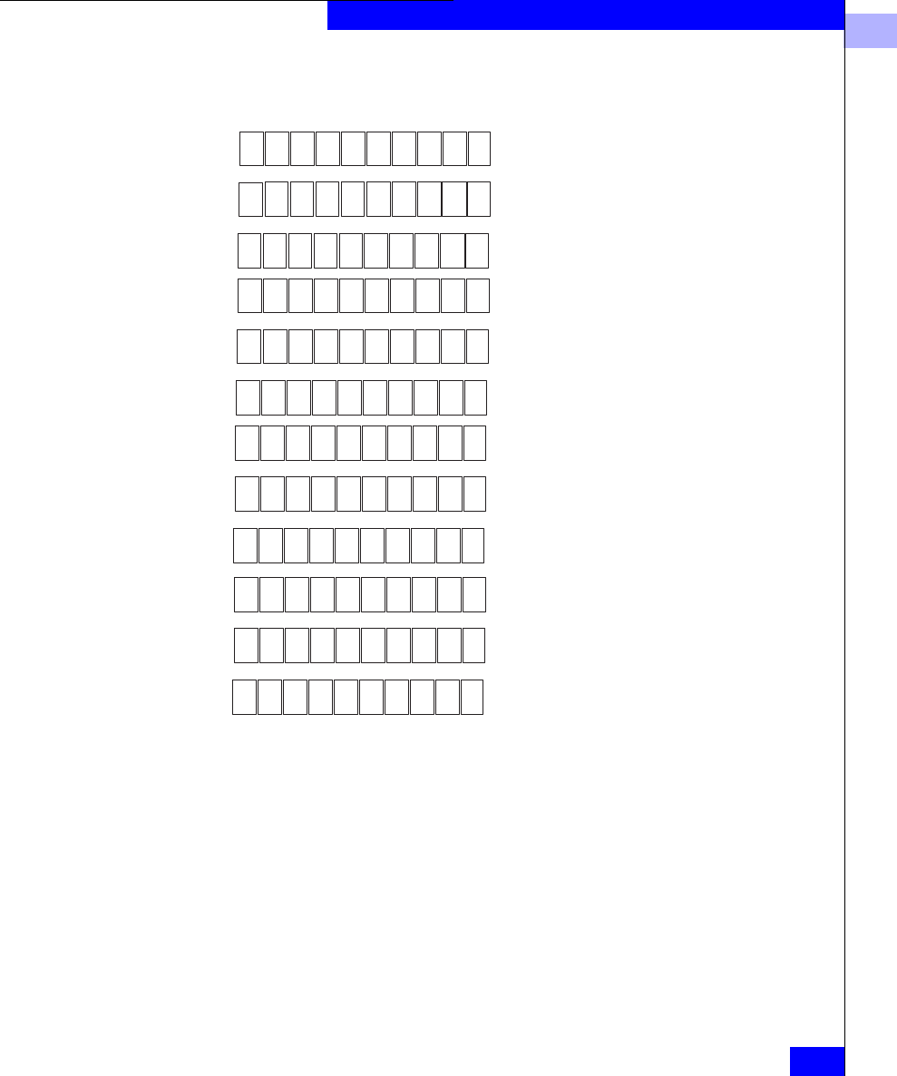
4
Planning Applications and LUNs
4-7
Planning LUNs and File Systems with Unshared Direct Storage
LUN Planning Worksheet - Rackmount
Full-fibre storage system
0_0 0_1 0_2 0_3 0_4 0_5 0_6 0_7 0_8 0_9
1_0 1_1 1_2 1_3 1_4 1_5 1_6 1_7 1_8 1_9
2_0 2_1 2_2 2_3 2_4 2_5 2_6 2_7 2_8 2_9
3_0 3_1 3_2 3_3 3_4 3_5 3_6 3_7 3_8 3_9
4_0 4_1 4_2 4_3 4_4 4_5 4_6 4_7 4_8 4_9
5_0 5_1 5_2 5_3 5_4 5_5 5_6 5_7 5_8 5_9
6_0 6_1 6_2 6_3 6_4 6_5 6_6 6_7 6_8 6_9
7_0 7_1 7_2 7_3 7_4 7_5 7_6 7_7 7_8 7_9
8_0 8_1 8_2 8_3 8_4 8_5 8_6 8_7 8_8 8_9
9_0 9_1 9_2 9_3 9_4 9_5 9_6 9_7 9_8 9_9
10_0 10_1 10_2 10_3 10_4 10_5 10_6 10_7 10_8 10_9
11_0 11_1 11_2 11_3 11_4 11_5 11_6 11_7 11_8 11_9
LUN number_______RAID type ___ Cap. (Gb) _____ Disk IDs_________________________________________
LUN number_______RAID type ___ Cap. (Gb) _____ Disk IDs_________________________________________
LUN number_______RAID type ___ Cap. (Gb) _____ Disk IDs_________________________________________
LUN number_______RAID type ___ Cap. (Gb) _____ Disk IDs_________________________________________
LUN number_______RAID type ___ Cap. (Gb) _____ Disk IDs_________________________________________
LUN number_______RAID type ___ Cap. (Gb) _____ Disk IDs_________________________________________
LUN number_______RAID type ___ Cap. (Gb) _____ Disk IDs_________________________________________
LUN number_______RAID type ___ Cap. (Gb) _____ Disk IDs_________________________________________
4
4-8
EMC Fibre Channel Storage Systems Configuration Planning Guide
Planning LUNs and File Systems with Unshared Direct Storage
LUN Planning Worksheet - Deskside
1_4
1_2
1_1
1_3
1_5
1_9
1_8
1_7
1_6
Full-fibre storage system
2_4
2_2
2_1
2_3
2_5
2_9
2_8
2_7
2_6
0_0
0_1
0_2
0_3
0_4
0_5
0_6
0_7
0_8
0_9
1_0 2_0
LUN number_______RAID type ___ Cap. (Gb) _____ Disk IDs_______________________________________
_
LUN number_______RAID type ___ Cap. (Gb) _____ Disk IDs_______________________________________
_
LUN number_______RAID type ___ Cap. (Gb) _____ Disk IDs_______________________________________
_
LUN number_______RAID type ___ Cap. (Gb) _____ Disk IDs_______________________________________
_
LUN number_______RAID type ___ Cap. (Gb) _____ Disk IDs_______________________________________
_
LUN number_______RAID type ___ Cap. (Gb) _____ Disk IDs_______________________________________
_
LUN number_______RAID type ___ Cap. (Gb) _____ Disk IDs_______________________________________
_
LUN number_______RAID type ___ Cap. (Gb) _____ Disk IDs_______________________________________
_
Storage system number_____
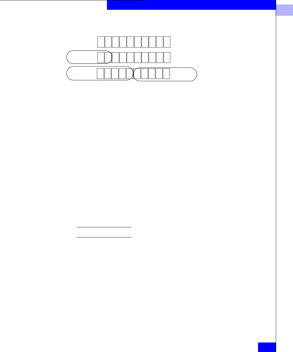
4
Planning Applications and LUNs
4-9
Planning LUNs and File Systems with Unshared Direct Storage
A sample LUN worksheet follows.
Completing the LUN Planning Worksheet
As shown, draw circles around the disks that will compose each
LUN, and within each circle specify the RAID type (for example,
RAID 5) and LUN ID. This is information you will use to bind the
disks into LUNs. For disk IDs, use the form shown. This form is
enclosure_diskID, where enclosure is the enclosure number (the bottom
one is 0, above it 1, and so on) and diskID is the disk position (left is 0,
next is 1, and so on).
None of the disks 0_0 through 0_8 may be used as a hot spare.
Next, complete as many of the LUN sections as needed for each
storage system.Copy the (blank) worksheet as needed for all LUNs in
each storage system. A storage system is any group of enclosures
connected to a DPE; a full-fibre system can include up to nine DAE
enclosures for a total of 100 disks.
LUN Details Worksheet Use the following LUN details worksheet to plan the individual
LUNs. Complete as many of these as needed for all LUNs.
0_0 0_1 0_2 0_3 0_4 0_5 0_6 0_7 0_8 0_9
1_0 1_1 1_2 1_3 1_4 1_5 1_6 1_7 1_8 1_9
2_0 2_1 2_2 2_3 2_4 2_5 2_6 2_7 2_8 2_9
LUN number_______RAID type ___ Cap. (Gb) _____ Disk IDs_________________________________________
LUN number_______RAID type ___ Cap. (Gb) _____ Disk IDs_________________________________________
LUN number_______RAID type ___ Cap. (Gb) _____ Disk IDs_________________________________________
LUN number_______RAID type ___ Cap. (Gb) _____ Disk IDs_________________________________________
LUN number_______RAID type ___ Cap. (Gb) _____ Disk IDs_________________________________________
LUN number_______RAID type ___ Cap. (Gb) _____ Disk IDs_________________________________________
LUN number_______RAID type ___ Cap. (Gb) _____ Disk IDs_________________________________________
LUN number_______RAID type ___ Cap. (Gb) _____ Disk IDs_________________________________________
1
LUN 0
RAID 5
LUN 1
RAID 5
LUN 2
RAID 1
1
0
0_0, 0_1, 0_2, 0_3, 0_4
5
144 0_5, 0_6, 0_7, 0_8, 0_9
144
5
21_0, 1_1
36
1

4
4-10
EMC Fibre Channel Storage Systems Configuration Planning Guide
Planning LUNs and File Systems with Unshared Direct Storage
LUN Details Worksheet
Storage system (complete this section once for each storage system)
Storage-system number or name:______
Storage-system installation type
❏Unshared Direct ❏Shared-or-Clustered Direct ❏Shared Switched
SP FC-AL address ID (unshared only): SP A:_____SP B:_____
SP memory (Mbytes): SP A:______ SP B:______
VUse for caching Read cache size:___ MB Write cache size: ___ MB Cache page size:___KB
VUse for RAID 3
LUN ID:_____
RAID Group ID: Size,GB: LUN size,GB: Disk IDs: SP: VAVB
RAID type: VRAID 5 VRAID 3 - Memory, MB:___ VRAID 1 mirrored pair VRAID 0
VRAID 1/0 VIndividual disk VHot spare
Caching: VRead and write VWrite VRead VNone
Servers that can access this LUN:
Operating system information: Device name: File system, partition, or drive:

4
Planning Applications and LUNs
4-11
Planning LUNs and File Systems with Unshared Direct Storage
LUN Details Worksheet
Storage system (complete this section once for each storage system)
Storage-system number or name:__1____
Storage-system installation type
❏Unshared Direct ❏Shared-or-Clustered Direct ❏Shared Switched
SP FC-AL address ID (unshared only): SP A:_____SP B:_____
SP memory (Mbytes): SP A:_128__ SP B:_128__
VUse for caching Read cache size:_40_ MBWrite cache size: _80_ MBCache page size:_2__KB
VUse for RAID 3
LUN ID:__0___
RAID Group ID: 0Size,GB: 144 LUN size,GB: 144 Disk IDs: SP: VAVB
RAID type: VRAID 5 VRAID 3 - Memory, MB:___ VRAID 1 mirrored pair VRAID 0
VRAID 1/0 VIndividual disk VHot spare
Caching: VRead and write VWrite VRead VNone
Servers that can access this LUN: Server1
Operating system information: Device name: File system, partition, or drive: T
LUN ID:__1__
RAID Group ID: 1 Size,GB: 144 LUN size,GB: 144 Disk IDs: SP: VAVB
RAID type: VRAID 5 VRAID 3 - Memory, MB:___ VRAID 1 mirrored pair VRAID 0
VRAID 1/0 VIndividual disk VHot spare
Caching: VRead and write VWrite VRead VNone
Servers that can access this LUN: Server1
Operating system information: Device name: File system, partition, or drive: U
LUN ID:__2__
RAID Group ID: 2Size,GB: LUN size,GB: 36 Disk IDs: SP: VAVB
RAID type: VRAID 5 VRAID 3 - Memory, MB:___ VRAID 1 mirrored pair VRAID 0
VRAID 1/0 VIndividual disk VHot spare
Caching: VRead and write VWrite VRead VNone
Servers that can access this LUN: Server1
Operating system information: Device name: File system, partition, or drive: V
X
X
0_0, 0_1, 0_2, 0_3, 0_4
0_5, 0_6, 0_7, 0_8, 0_9
18
X
X
X
X
X
X
1_0, 1_1
X
X
X

4
4-12
EMC Fibre Channel Storage Systems Configuration Planning Guide
Planning LUNs and File Systems with Unshared Direct Storage
Completing the LUN Details Worksheet
Complete the header portion of the worksheet for each storage
system as described below. Copy the blank worksheet as needed.
Sample completed LUN worksheets appear later.
Storage-System Entries
Storage-system configuration. Specify Unshared Direct (one server)
or Shared-or-Clustered Direct (two servers).
For any multiple-server configuration, each server will need cluster
software.
SP FC-AL address ID. For unshared storage, which uses FC-AL
addressing, each SP (and each other node) on a Fibre Channel loop
must have a unique FC-AL address ID. You set the SP FC-AL address
ID using switches on the back panel of the SP. The valid FC-AL
address ID range is a number 0 through 125 decimal, which is 0
through 7D hexadecimal. For any number above 9, we suggest
hexadecimal, since the switches are marked in hexadecimal.
If you have two FC-AL loops, we suggest a unique FC-AL address ID
for each SP on both loops.
SP memory. Enter the amount of memory each SP has. If a storage
system has two SPs, they will generally have the same amount of
memory. You can allocate this memory to storage-system caching or
RAID 3 use.
Use memory for caching. You can use SP memory for read/write
caching or RAID 3. (Using both caching and RAID 3 in the same
storage system not recommended.) You can use different cache
settings for different times of day (for example, for user I/O during
the day, use more write cache; for sequential batch jobs at night, use
more read cache. You enable caching for specific LUNs — allowing
you to tailor your cache resources according to priority. If you choose
caching, check the box and continue to the next step; for RAID 3, skip
to the RAID Group ID entry.
Read cache size. If you want a read cache, it should generally be
about one third of the total available cache memory.
Write cache size. The write cache should be two thirds of the total
available. Some memory is required for system overhead, so you
cannot determine a precise figure at this time. For example, for 256
Mbytes of total memory, you might have 240 Mbytes available, and

4
Planning Applications and LUNs
4-13
Planning LUNs and File Systems with Unshared Direct Storage
you would specify 80 Mbytes for the read cache and 160 Mbytes for
the write cache.
Cache page size. This applies to both read and write caches. It can be
2, 4, 8, or 16 Kbytes. As a general guideline, we suggest
For a general-purpose file server — 8 Kbytes
For a database application — 2 or 4 Kbytes
The ideal cache page size depends on the operating system and
application.
Use memory for RAID 3. If you want to use the SP memory for
RAID 3, check the box.
RAID Group/LUN Entries
Complete a RAID Group/LUN entry for each LUN and hot spare.
LUN ID. The LUN ID is a hexadecimal number assigned when you
bind the disks into a LUN. By default, the ID of the first LUN bound
is 0, the second 1, and so on. Each LUN ID must be unique within the
storage system, regardless of its Storage Group or RAID Group.
The maximum number of LUNs supported on one host-bus adapter
depends on the operating system. Some systems allow only eight
LUNs (numbers 0 through 7). For an operating system with this
restriction, if you want a hot spare, assign the hot spare an ID above
7; for example, 8 or 9. The operating system never accesses a hot
spare, so the ID is irrelevant to it.
RAID Group ID. This is a hexadecimal number assigned when you
create the RAID Group. By default, the number of the first RAID
Group in a storage system is 0, the second 1, and so on, up to the
maximum of 1F (31).
Size (RAID Group size) Enter the user-available capacity in gigabytes
(Gbytes) of the whole RAID Group. You can determine the capacity
as follows:
RAID-5 or RAID-3 Group: disk-size * (number-of-disks - 1)
RAID 1/0 or RAID-1
Group: (disk-size * number-of-disks) / 2
RAID-0 Group: disk-size * number-of-disks
Individual unit: disk-size

4
4-14
EMC Fibre Channel Storage Systems Configuration Planning Guide
Planning LUNs and File Systems with Unshared Direct Storage
For example,
•A five-disk RAID 5 or RAID 3 Group of 36-Gbyte disks holds
144 Gbytes;
•An eight-disk RAID 1/0 Group of 36-Gbyte disks also holds
144Gbytes;
•A RAID 1 mirrored pair of 36-Gbyte disks holds 36 Gbytes; and
•An individual disk of a 36-Gbyte disk also holds 36 Gbytes.
Each disk in the RAID Group must have the same capacity;
otherwise, you will waste disk storage space.
LUN Size. Enter the user-available capacity in gigabytes (Gbytes) of
the LUN. You can make this the same size as the RAID Group, above.
Or, for a RAID 5, RAID 1, RAID 1/0, or RAID 0 Group, you can make
the LUN smaller than the RAID Group. You might do this if you
wanted a RAID 5 Group with a large capacity and wanted to place
many smaller capacity LUNs on it; for example, to specify a LUN for
each user. However, having multiple LUNs per RAID Group may
adversely impact performance. If you want multiple LUNs per RAID
Group, then use a RAID Group/LUN series of entries for each LUN.
Disk IDs. Enter the ID(s) of all disks that will make up the LUN or
hot spare. These are the same disk IDs you specified on the previous
worksheet. For example, for a RAID-5 Group in the DPE (enclosure 0,
disks 2 through 6), enter 0_2, 0_3, 0_4, 0_5, and 0_6.
SP. Specify the SP that will own the LUN: SP A or SP B. You can let
the management program automatically select the SP to balance the
workload between SPs; to do so, leave this entry blank.
RAID type. Copy the RAID type from the previous worksheet. For
example, RAID 5 or hot spare. For a hot spare (not strictly speaking a
LUN at all), skip the rest of this LUN entry and continue to the next
LUN entry (if any).
If this is a RAID 3 Group, specify the amount of SP memory for that
group. To work efficiently, each RAID 3 Group needs at least
6Mbytes of memory.
Caching. If you want to use caching (entry on page 4-12), you can
specify whether you want caching — read and write, read, or write
for this LUN. Generally, write caching improves performance far
more than read caching. The ability to specify caching on a LUN basis
provides additional flexibility, since you can use caching for only the

4
Planning Applications and LUNs
4-15
Planning LUNs and File Systems with Unshared Direct Storage
units that will benefit from it. Read and write caching
recommendations follow.
Table 4-1 Cache Recommendations for Different RAID Types
Servers that can access this LUN. Enter the name of each server that
will be able to use the LUN. Normally, you need to restrict access by
establishing SP ownership of LUNs when you bind them.
Operating system information: Device name. Enter the operating
system device name, if this is important and if you know it.
Depending on your operating system, you may not be able to
complete this field now.
File system, partition, or drive. Write the name of the file system,
partition, or drive letter you will create on this LUN. This is the same
name you wrote on the application worksheet.
On the following line, write any pertinent notes; for example, the file
system mount- or graft-point directory pathname (from the root
directory). If this storage system’s chassis will be shared with another
server, and the other server is the primary owner of this disk, write
secondary. (If the storage system will be used by two servers, we
suggest you complete one of these worksheets for each server.)
What Next? This chapter outlined the planning tasks for unshared storage
systems. If you have completed the worksheets to your satisfaction,
you are ready to learn about the hardware needed for these systems
as explained in Chapter 5.
RAID 5 RAID 3 RAID 1 RAID 1/0 RAID 0 Individual Unit
Highly Recommended Not allowed Recommended Recommended Recommended Recommended


Storage System Hardware
5-1
5
Invisible Body Tag
This chapter describes the storage-system hardware components.
Topics are
•Hardware for Shared Storage...........................................................5-3
•Hardware for Unshared Storage......................................................5-6
•Planning Your Hardware Components ........................................5-11
•Hardware Data Sheets.....................................................................5-14
•Cabinets for Rackmount Enclosures .............................................5-20
•Cable and Configuration Guidelines ............................................5-21
•Hardware Planning Worksheets....................................................5-24
Storage System
Hardware
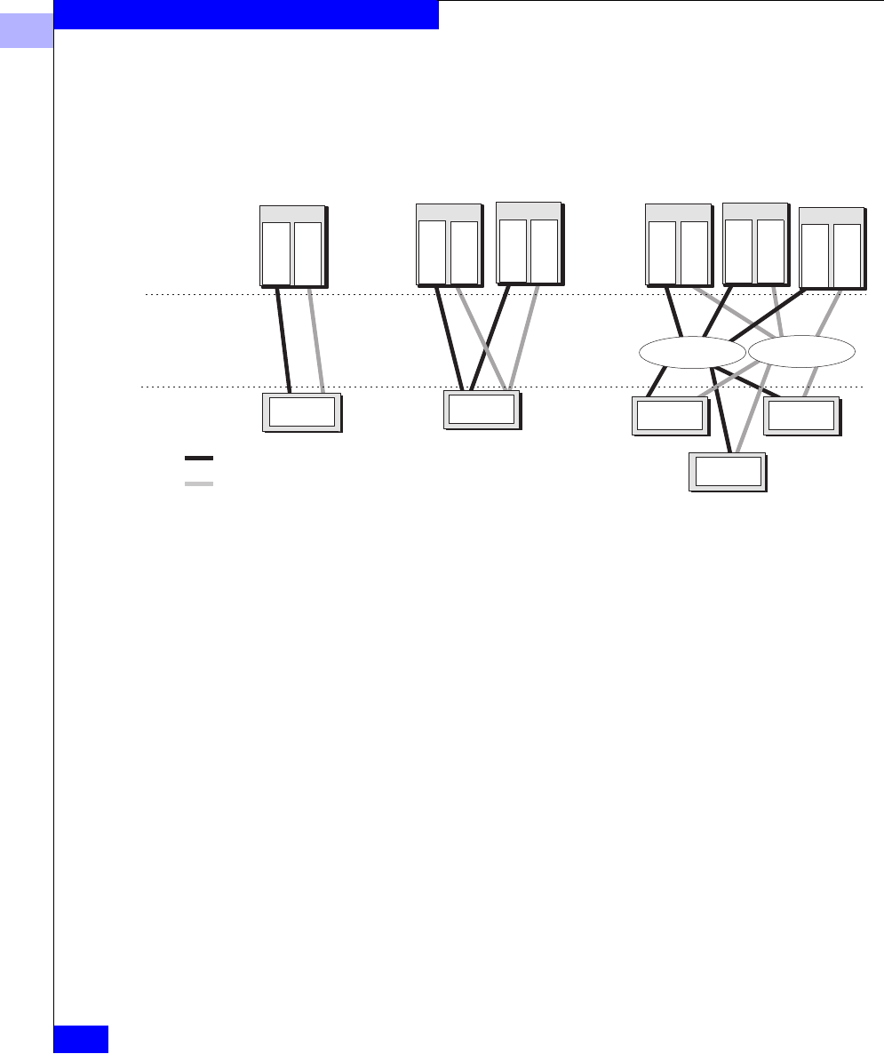
5
5-2
EMC Fibre Channel Storage Systems Configuration Planning Guide
Storage System Hardware
The storage systems attach to the server and the interconnect
components described in Chapter 1.
Figure 5-1 Shared and Unshared Storage
Disk-array storage systems
Server
Adapter
Adapter
Server
Adapter
Adapter
Server
Adapter
Adapter
Server
Adapter
Adapter
Server
Adapter
Adapter
Server
Adapter
Adapter
Shared-or-Clustered Direct
(two servers)
Switch fabric Switch fabric
Shared Switched
(multiple servers)
Unshared Direct
(one server)
Server
component
Interconnect
component
Storage
component
FC loop 2
FC loop 1
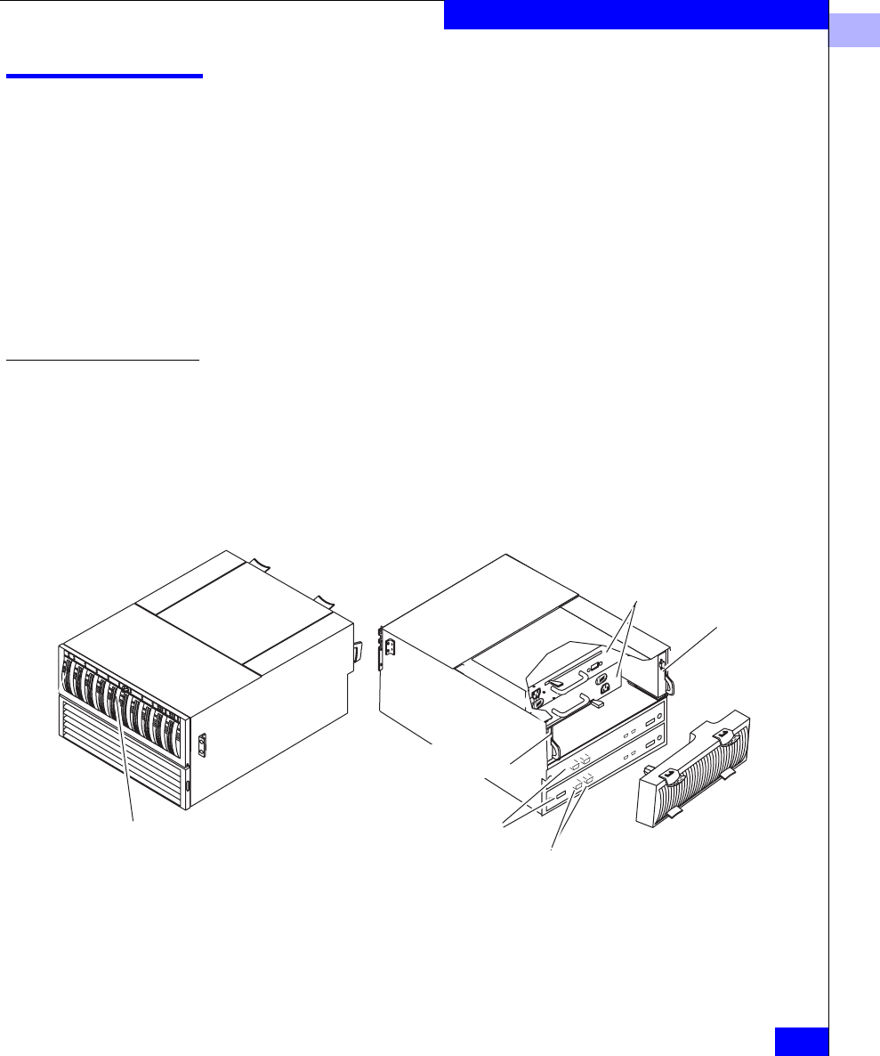
5
Hardware for Shared Storage
5-3
Storage System Hardware
Hardware for Shared Storage
The primary hardware component for shared storage is a ten-slot
Disk-array Processor Enclosure (DPE) with two storage processors
(SP). The DPE can support up to nine separate 10-slot enclosures
called Disk Array Enclosures (DAEs) for a total of 100 disks. Shared
storage requires two SPs and the Access Logix software option.
A DPE with a DAE is available as a deskside system, but with a
capacity of 20 disks this cannot provide the expandability and total
storage capacity needed for a SAN (storage area network). So this
section does not cover the deskside version.
Storage Hardware — Rackmount DPE-Based Storage Systems
The DPE rackmount enclosure is a sheet-metal housing with a front
door, a midplane, and slots for the storage processors (SPs), link
control cards (LCCs), disk modules, power supplies, and fan packs.
All components can be replaced under power. The DPE rackmount
model looks like the following figure.
Figure 5-2 DPE Storage-System Components – Rackmount Model
A separate standby power supply (SPS) is required to support write
caching. All the shared storage components — rackmount DPE,
DAEs, SPSs, and cabinet — are shown in the following figure.
Back
Power supplies
Storage processors (SPs) Drive fan module
(detached for clarity)
Link control
card (LCC)
LCC
Disk modules (front door
removed for clarity)
Front
FC ports with GBICs
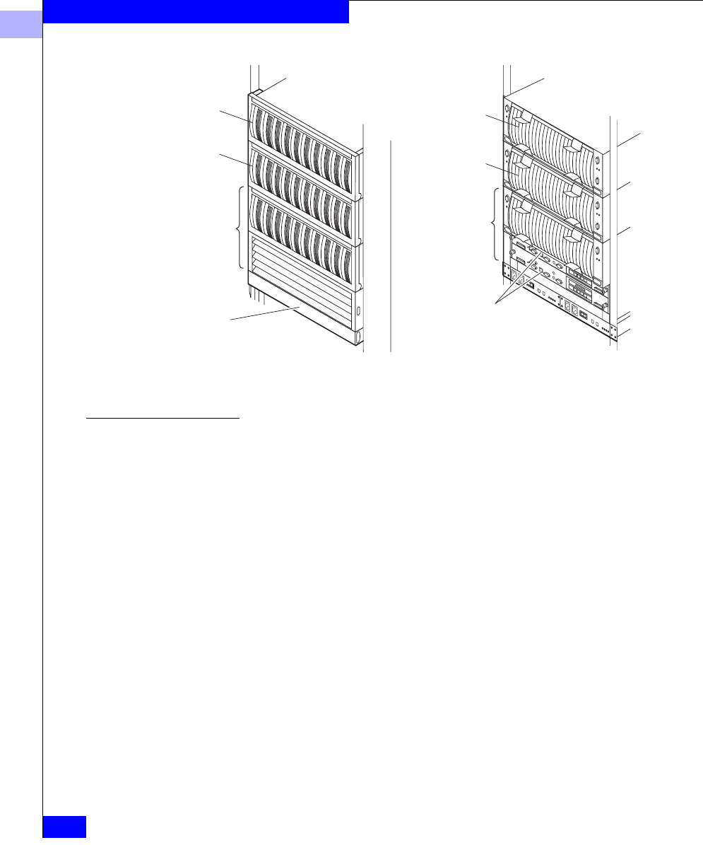
5
5-4
EMC Fibre Channel Storage Systems Configuration Planning Guide
Storage System Hardware
Figure 5-3 Rackmount System with DPE and DAEs
Disks The disks — available in differing capacities — fit into slots in the
enclosure. Each module has a unique ID that you use when binding
or monitoring its operation. The ID is derived from the enclosure
address (always 0 for the DPE, settable on a DAE) and the disk
module slot numbers.
EMC1744
Rear
Front
DPE
DPE
DAE
DAE
DAE
DAE
SPs
Standby power
supplies (SPSs)
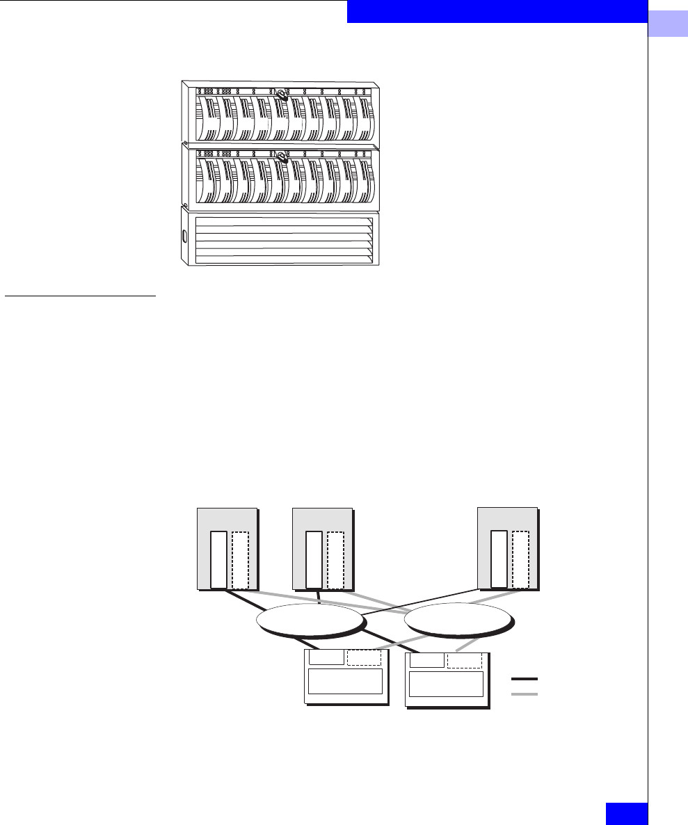
5
Hardware for Shared Storage
5-5
Storage System Hardware
Disk Modules and Module IDs — Rackmount DPE-Based System
Storage Processor (SP)
The SP provides the intelligence of the storage system. Using its own
operating system (called Core Software), the SP processes the data
written to or read from the disk modules, and monitors the modules
themselves. An SP consists of a printed-circuit board with memory
modules (DIMMs), and status lights.
For high availability, a storage system can support a second SP. The
second SP provides a second route to a storage system and also lets
the storage system use write caching for enhanced write
performance. Two SPs are required for shared storage.
Figure 5-4 Shared Storage Systems
See Chapter 3 for more examples of shared storage.
0123456789
10 11 12 13 14 15 16 17 18 19
SP A
Server Server
SP B
Storage systems
Switch fabric
Adapter
Adapter
Adapter
Adapter
Adapter
Adapter
Server
SP A SP B
Switch fabric
Path 1
Path 2

5
5-6
EMC Fibre Channel Storage Systems Configuration Planning Guide
Storage System Hardware
Hardware for Unshared Storage
Unshared storage systems are less costly and less complex than
shared storage systems. They offer many shared storage system
features; for example, you can use multiple unshared storage systems
with multiple servers. However, with multiple servers, unshared
storage offers less flexibility and security than shared storage, since
any user with write access to privileged server files can enable access
to any storage system.
Types of Storage System for Unshared Storage
For unshared storage, there are four types of storage system, each
using the FC-AL protocol. Each type is available in a rackmount or
deskside (office) version.
•Disk-array Processor Enclosure (DPE) storage systems. A DPE is
a 10-slot enclosure with hardware RAID features provided by one
or two storage processors (SPs). In addition to its own disks, a
DPE can support up to 110 additional disks in 10-slot Disk Array
Enclosures (DAEs) for a total of 120 disks. This is the same kind of
storage system used for shared storage, but it uses a different
storage processor (SP).
•Intelligent Disk Array Enclosure (iDAE). An iDAE, like a DPE,
has SPs and thus all the features of a DPE, but is thinner and has a
limit of 30 disks.
•Disk Array Enclosure (DAE). A DAE does not have SPs. A DAE
can connect to a DPE or an iDAE, or you can use it without SPs. A
DAE used without an SP does not inherently include RAID, but
can operate as a RAID device using software running on the
server system. Such a DAE is also known as Just a Box of Disks, or
JBOD.
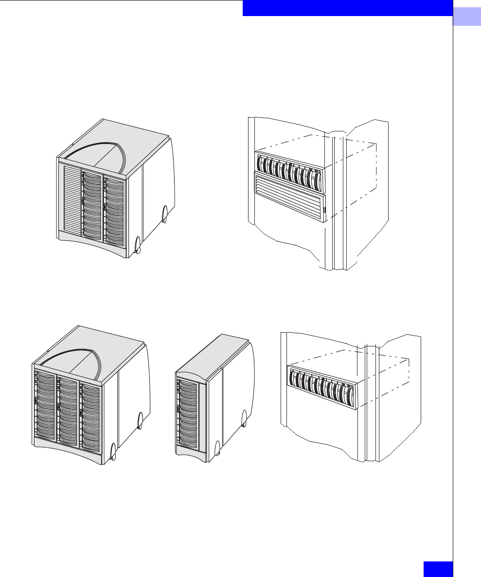
5
Hardware for Unshared Storage
5-7
Storage System Hardware
Figure 5-5 Storage System Types for Unshared Storage
Deskside DPE with DAE Rackmount DPE, one enclosure,
supports up to 9 DAEs
Disk-array processor enclosure (DPE)
Intelligent disk-array enclosure (iDAE)
30-slot deskside Rackmount10-slot deskside
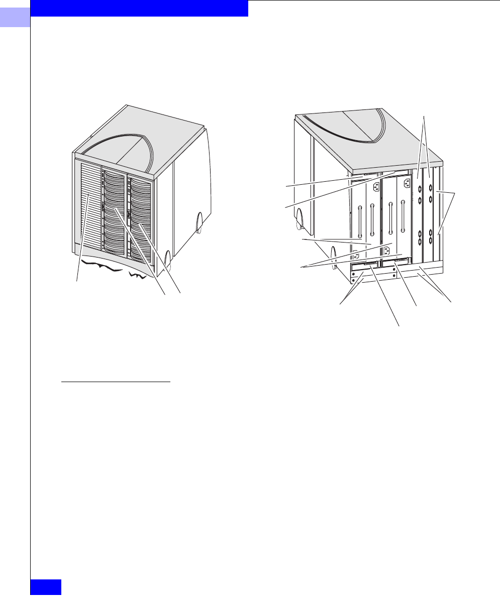
5
5-8
EMC Fibre Channel Storage Systems Configuration Planning Guide
Storage System Hardware
The following figure shows some components of a deskside DPE.
Components for rackmount types are similar.
Figure 5-6 DPE Components - Deskside Model
Disks The disks — available in differing capacities — fit into slots The disks — available in differing capacities — fit into slots in the
enclosure. Each disk has a unique ID that you use when binding it or
monitoring its operation. The ID is the enclosure address (always 0
for the DPE, settable on a DAE) and the disk slot number.
Front Back (fans and cables
omitted for clarity)
DPE DAE
DAE link control
card (LCC)
DAE LCC
DPE LCC
DPE LCC
Storage processors
(SPs)
FC ports
DAE power supplies
DPE power supplies
SPS units
Power distribution
units
Front doors
(cover disk modules)
SP fan cover
(covers SP
fan pack)
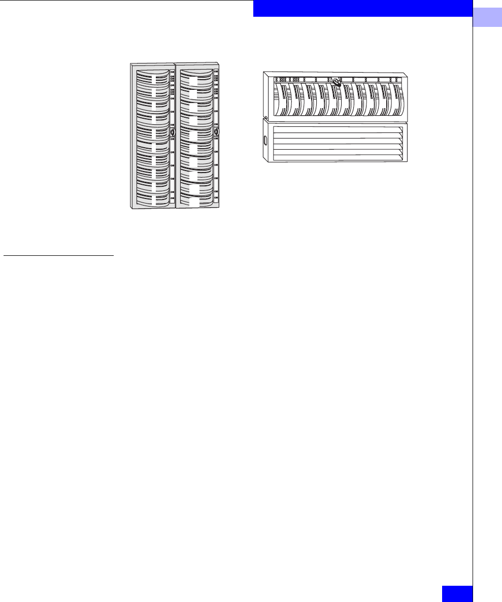
5
Hardware for Unshared Storage
5-9
Storage System Hardware
Figure 5-7 Disks and Disk IDs
Storage Processor (SP)
The SP provides the intelligence of the storage system. Using its own
operating system (called Core Software), the SP processes the data
written to or read from the disk modules, and monitors the modules
themselves. An SP consists of a printed-circuit board with memory
modules (DIMMs), status lights, and switches for setting FC-AL
addresses.
For high availability, a storage system can support a second SP. A
second SP provides a second route to a storage system, so both SPs
can connect to the same server or two different servers, as follows.
0
1
2
3
4
5
6
7
8
9
10
11
12
13
14
15
16
17
18
19
01 2 3456 7 89
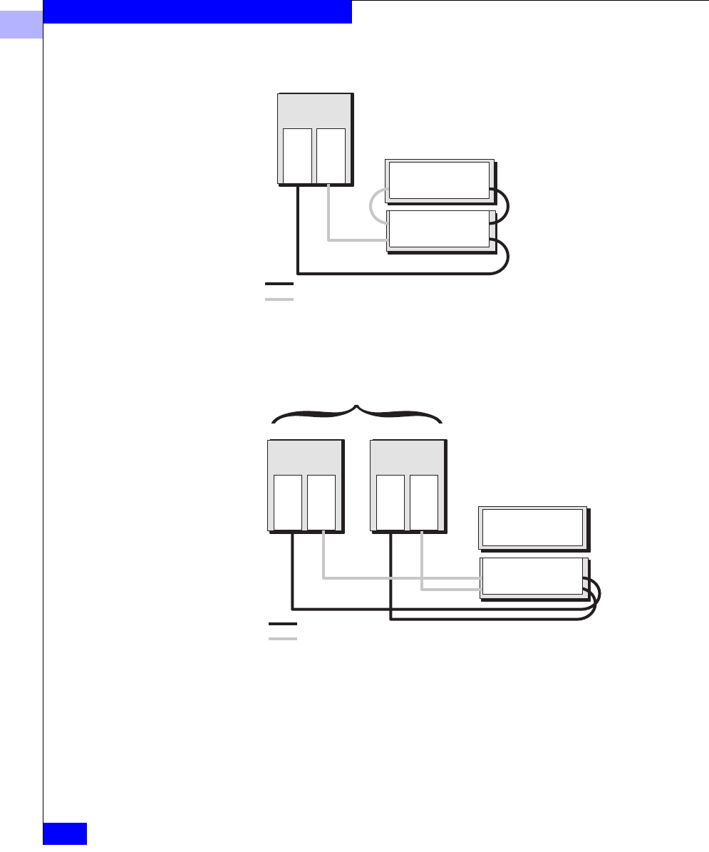
5
5-10
EMC Fibre Channel Storage Systems Configuration Planning Guide
Storage System Hardware
Figure 5-8 Storage System with Two SPs Connected to the Same Server
Figure 5-9 Storage System with Two SPs Connected to Different Servers
Either SP can control any LUN in the storage system, but only one SP
at a time can control a LUN. If one SP cannot access a LUN it
controlled (because of a failure), you can transfer control of the LUN
to the other SP, manually or via software.
Server
Cables
FC loop 1
FC loop 2
Storage system
DAE(s)
Adapter
Adapter
DPE
SP A SP B
FC loop 1
FC loop 2
Highly available cluster
Storage system
DAE(s)
Adapter
Adapter
Server 2Server 1
Adapter
Adapter
DPE
SP A SP B

5
Planning Your Hardware Components
5-11
Storage System Hardware
Storage-system caching provides significant performance
enhancement. Read caching is available with one or two SPs.
Mirrored write caching, particularly helpful with RAID 5 I/O,
requires two SPs (to mirror one another, for cache integrity) and a
Standby Power Supply (SPS) to enable the SPs to write their cached
data to disk if power fails.
Planning Your Hardware Components
This section helps you plan the hardware components — adapters,
switches or hubs, cables, storage systems, and site requirements —
for each server in your installation.
For shared storage, you must use a DPE rackmount system with two
SPs and high-availability options. We assume you have some idea of
how many servers, adapters, switches or hubs, storage systems, and
SPs you want. Skip to the component data sheets following.
For unshared storage, you can use one or two SPs and you can choose
among storage system configurations. This section assumes you have
examined the configurations shown starting on page 4-2 and have
some idea of how many servers, adapters, switches or hubs, storage
systems, and SPs you want. It ends with blank worksheets and
sample worksheets.
Configuration Tradeoffs - Shared Storage
The hardware configuration required for shared storage is very
specific: two host-bus adapters in each attached server, two Fibre
Channel switches, and two SPs per storage system. Choices you can
make with shared storage systems include the number of storage
systems (up to 15 are allowed), and for each storage system the cache
configuration (maximum or minimum), and one or two standby
power supplies (SPS units).
The number of storage systems in the SAN depends on the servers’
processing demands. For each system, the larger cache improves
write performance for very large processing loads; the redundant SPS
lets write caching continue if one SPS fails.

5
5-12
EMC Fibre Channel Storage Systems Configuration Planning Guide
Storage System Hardware
Configuration Tradeoffs - Unshared Storage
For each storage-system enclosure, you have two important areas of
choice: rackmount or deskside model, and high-availability options.
Generally, rackmount systems are more versatile; you can add
capacity in a cabinet without consuming more floor space. However,
rackmount systems require additional hardware, such as cabinets
and mounting rails, and someone must connect power cords and
cables within them. For large storage requirements, rackmount
systems may be more economical than deskside systems. Deskside
systems are more convenient; they ship with all internal cabling in
place and require only ac power and connection to the servers.
For high availability, there are many variations. The most important
high-availability features are a second SP/LCC pair, second power
supply, and standby power supply (SPS). The second SP/LCC and
SPS let you use write caching to enhance performance; the second SP
provides continuous access to storage-system disks if one SP or LCC
fails. Another high-availability option is a redundant SPS.
Yet another option, for a deskside system, is a second power
distribution unit (PDU), which lets you route ac power from an
independent source. Used this way, the second PDU protects against
failure in one of the two ac power sources. With a rackmount system,
you can acquire a cabinet with one or two ac inlet cords. The second
inlet cord, connected to a second ac power source, provides the same
advantage for all storage systems in the cabinet as the second PDU in
the deskside storage system.
For deskside systems, the optional high-availability hardware fits
into the deskside cabinet. Deskside high-availability options are as
follows.
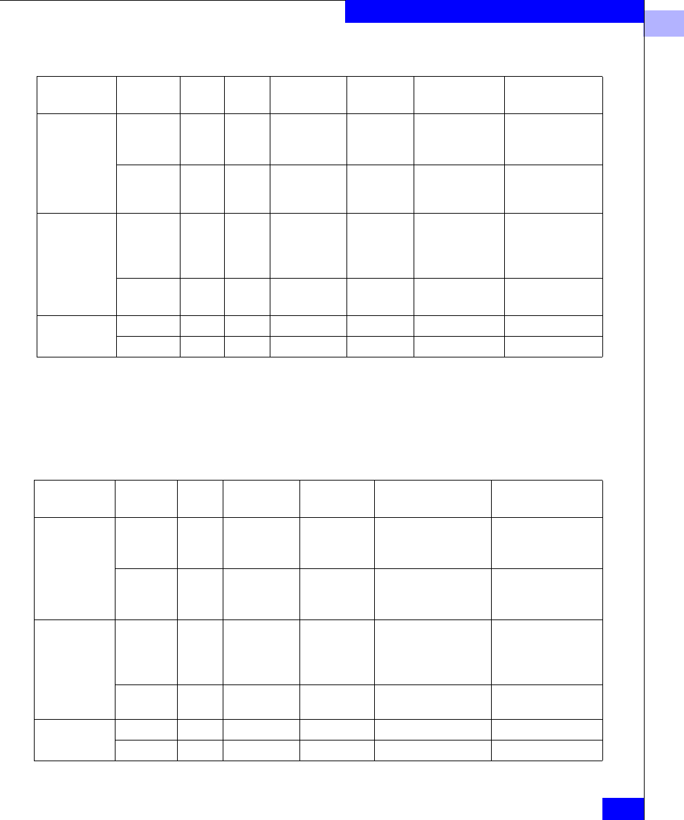
5
Planning Your Hardware Components
5-13
Storage System Hardware
Table 5-1 High-Availability Options, Deskside Unshared Storage
For rackmount systems, the standby power supply or supplies (SPS
or BBU) must be placed in a tray directly beneath the storage system.
Typically, any hubs in the cabinet mount at the top or bottom of the
cabinet. Rackmount options are as follows.
Table 5-2 High-Availability Options, Rackmount Unshared Storage
Deskside
System Type HA Level PDUs SPs LCCs
Power
Supplies Disks SPS Units
DPE Minimum 1 1 1 DPE
1 DAE
1 DPE
1 DAE
5 (without write
cache)
0 (without write
cache)
1 (write cache)
Maximum 2 2 4 (2 DPE
2 DAE)
4
(2 DPE
2 DAE)
10 (write cache
or RAID 3)
2
iDAE Minimum 1 1 n/a (10-slot)
2 (30-slot)
1 3 (without write
cache)
5 (write cache
or RAID 3)
0 (without write
cache)
1 (write cache
Maximum 2 2 n/a (10-slot)
4 (30-slot)
2 (10-slot)
6 (30-slot)
5 (write cache
or RAID 3)
2
DAE only Minimum 1 n/a 1 1 No minimum n/a
Maximum 2 n/a 2 2 No minimum n/a
Rackmount
System Type HA Level SPs LCCs
Power
Supplies Disks SPS Units
DPE Minimum 1 1 1 5 (without write
cache)
0 (without write
cache)
1 (write cache)
Maximum 2 2 (DPE)
18 (with 9
DAEs)
2 (DPE)
11 (with 9
DAEs)
10 (write cache or
RAID 3)
2
iDAE Minimum 1 n/a (10-slot)
4 (with two
DAEs)
1 3 (without write
cache)
5 (write cache or
RAID 3)
0 (without write
cache)
1 (write cache
Maximum 2 n/a 2 5 (write cache or
RAID 3)
2
DAE only Minimum n/a 1 1 No minimum n/a
Maximum n/a 2 2 No minimum n/a
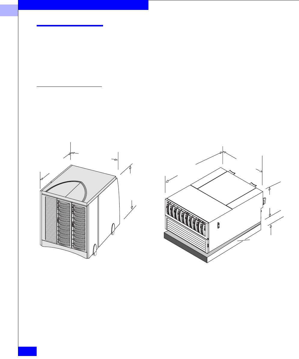
5
5-14
EMC Fibre Channel Storage Systems Configuration Planning Guide
Storage System Hardware
Hardware Data Sheets
The hardware data sheets shown in this section provide the plant
requirements, including dimensions (footprint), weight, power
requirements, and cooling needs, for DPE, iDAE, DAE, and 30-slot
SCSI disk systems. Sections on cabinets and cables follow the data
sheets.
DPE Data Sheet For shared storage, a rackmount DPE and one or more rackmount
DAEs are required. For unshared storage, you can use a rackmount or
deskside DPE and DAE(s). The DPE dimensions and requirements
are shown in the following figure.
DPE Dimensions and Requirements
Width
52.1 cm
(20.6 in)
Depth
74.7 cm
(30 in)
Height
68 cm
(26.8 in) Height
28.6 c
m
(11.3 in
)
6.5 U
Deskside model Rackmount model
Width
44.5 cm
(17.5 in)
Depth
70 cm
(27.6 in)
SPS mounting tra
y
height 4.44 cm
(1.75 in), 1 U;
depth 54.1 cm
(21.3 in)
Weight (without packaging) Deskside Rackmount
Maximum (max disks, SPs,
LCCs, PSs): 144 kg (316 lb) 52 kg (115 lb)
with 2 SPSs 165 kg (364 lb) 74 kg (163 lb)

5
Hardware Data Sheets
5-15
Storage System Hardware
Power requirements
Voltage rating: 100 V ac to 240 V ac –10%/+15%,
single-phase, 47 Hz to 63 Hz;
power supplies are auto-ranging
Current draw: At 100 v ac input – Deskside
DPE/DAE: 12.0 A; Rackmount
DPE: 8.0 A max; SPS: 1.0 A max per
unit during charge
Power consumption: Deskside DPE/DAE: 1200 VA;
Rackmount DPE: 800 VA max SPS:
1.0 A per unit during charge
Power cables (single or dual)
ac inlet connector: IEC 320-C14 power inlet
Deskside power cord: USA: 1.8 m (6.0 ft):
NEMA 6-15P plug
Outside USA Specific to country
Operating environment
Temperature: 10oC to 40oC (50o F to 104o F)
Relative humidity: Noncondensing, 20% to 80%
Altitude: 40oC to 2,438 m (8,000 ft); 37oC to 3,050 m
(10,000 ft)
Heat dissipation (max): Deskside DPE/DAE: 3931x103 J/hr (2730
BTU/hr) max estimated;
Rackmount DPE: 2520x103 J/hr (2390
BTU/hr) max estimated
Air flow: Front to back
Service clearances
Front: 30.3 cm (1 ft)
Back: 60.6 cm (2 ft)
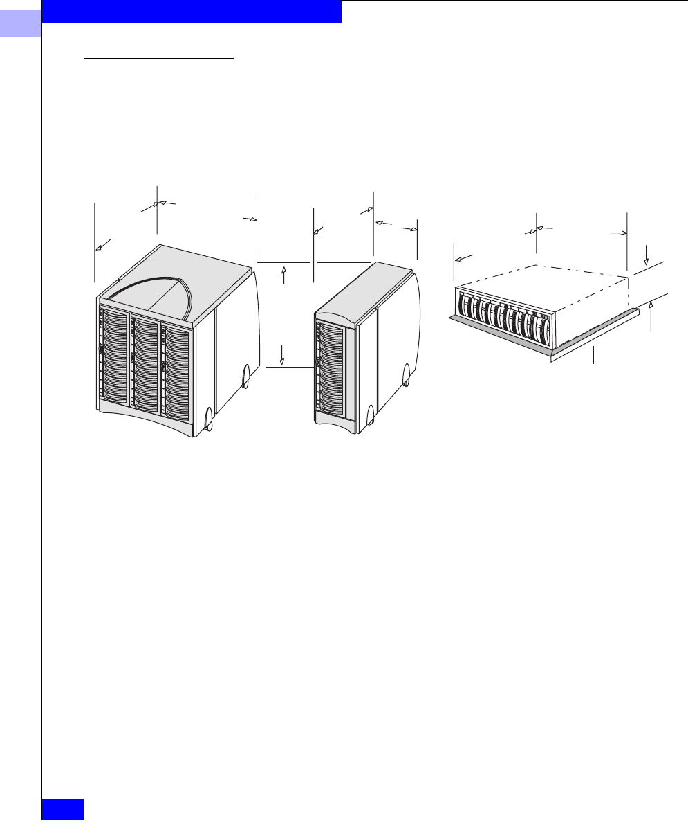
5
5-16
EMC Fibre Channel Storage Systems Configuration Planning Guide
Storage System Hardware
iDAE Data Sheet You can use a rackmount or deskside DPE and DAE(s) for unshared
storage. The iDAE dimensions and requirements are shown in the
following figure.
Dimensions and Requirements, iDAE
Width
52.1 cm
(20.6 in)
Depth
74.7 cm
(30 in)
Height
68 cm
(26.8 in)
Depth
74.7 cm
(30 in)
Width
25 cm
(9.8 in)
Height
15.4 cm
(6.1 in)
3.5 U
Deskside 30-slot model Rackmount model
Width
44.5 cm
(17.5 in)
Depth
63.3 cm
(24.9 in)
Deskside 10-slot model
SPS mounting tray,
height 4.44 cm
(1.75 in), 1 U;
depth 69.9 cm
(27.5 in)
Weight (without
packaging) Deskside 30 Deskside 10 Rackmount
Maximum (max
disks, SPs): 144 kg (316 lb) 60 kg (132 lb) 35.4 kg (78 lb)
Power requirements
Voltage rating: 100 V ac to 240 V ac +/- 10%, single-phase,
47 Hz to 63 Hz; power supplies are
auto-ranging
Current draw: At 100 v ac input – 30-slot 12.0 A; 10-slot: 4.0
A; SPS: 1.0 A max per unit during charge
Power consumption: 30-slot: 1200;10-slot: 400 VA; SPS: 100 VA
per unit during charge

5
Hardware Data Sheets
5-17
Storage System Hardware
Power cables (single or dual)
ac inlet connector: IEC 320-C14 power
inlet
Deskside power cord: USA: 1.8 m (6.0 ft): NEMA
6-15P plug
Outside USA: Specific to country
Operating environment
Temperature: 10oC to 40oC (50o F to 104o F)
Relative humidity: Noncondensing, 20% to 80%
Altitude: 40oC to 2,438 m (8,000 ft); 37oC to 3,050 m
(10,000 ft)
Heat dissipation (max): 30-slot: 4,233 KJ/hr (4,020 BTU/hr)
10-slot: 1,411 KJ/hr (1,340 BTU/hr)
Air flow: Front to back
Service clearances
Front: 30.3 cm (1 ft)
Back: 60.6 cm (2 ft)

5
5-18
EMC Fibre Channel Storage Systems Configuration Planning Guide
Storage System Hardware
DAE Data Sheet The DAE storage-system dimensions and requirements are shown in
the following figure.
Dimensions and Requirements, DAE
Width
52.1 cm
(20.6 in)
Depth
74.7 cm
(30 in)
Height
68 cm
(26.8 in)
Depth
74.7 cm
(30 in)
Width
25 cm
(9.8 in)
Height
15.4 cm
(6.1 in)
3.5 U
Deskside 30-slot model Rackmount model
Width
44.5 cm
(17.5 in)
Depth
63.3 cm
(24.9 in)
Deskside 10-slot model
Weight (without
packaging) Deskside 30 Deskside 10 Rackmount
Maximum (max
disks, SPs) 144 kg (316 lb) 60 kg (132 lb) 35.4 kg (78 lb)
Power requirements
Voltage rating: 100 V ac to 240 V ac +/- 10%, single-phase,
47 Hz to 63 Hz; power supplies are
auto-ranging
Current draw: At 100 v ac input – 30-slot 12.0 A; 10-slot: 4.0
A; SPS: 1.0 A max per unit during charge*
Power consumption: 30-slot: 1200;10-slot: 400 VA; SPS: 1.0 VA per
unit during charge

5
Hardware Data Sheets
5-19
Storage System Hardware
Power cables (single or dual)
ac inlet connector: IEC 320-C14 power
inlet
Deskside power cord: USA: 1.8 m (6.0 ft): NEMA
6-15P plug
Outside USA: Specific to country
Operating environment
Temperature: 10oC to 40oC (50o F to 104o F)
Relative humidity: Noncondensing, 20% to 80%
Altitude: 40oC to 2,438 m (8,000 ft); 37oC to 3,050 m
(10,000 ft)
Heat dissipation (max): 30-slot: 4,233 KJ/hr (4,020 BTU/hr)
10-slot: 1,411 KJ/hr (1,340 BTU/hr)
Air flow: Front to back
Service clearances
Front: 30.3 cm (1 ft)
Back: 60.6 cm (2 ft)
5
5-20
EMC Fibre Channel Storage Systems Configuration Planning Guide
Storage System Hardware
Cabinets for Rackmount Enclosures
Prewired 19-inch-wide cabinets, ready for installation, are available
in the following dimensions to accept rackmount storage systems.
As an example, a rackmount storage system that supports 100 disk
modules has the following requirements.
Vertical Space Exterior Dimensions Comments
173 cm or 68.25 in
(39 NEMA units or
U; one U is 1.75 in)
Height: 192 cm (75.3 in)
Width: 65 cm (25.5 in)
Depth: 87 cm (34.25 in) plus service
clearances, which are 90 cm (3 ft),
30 cm front and 60 cm back
Weight (empty): 134 kg (296 lb)
Accepts combinations of:
DPEs at 6.5 U,
iDAEs at 3.5 U,
SPS units at 1 U,
DAEs at 3.5 U each,
Switches or hubs at 1 U
Requires 200–240 volts ac. Plug options
include L6–30 or L7–30 (domestic) and
IEC 309 30 A (international).
Each power strip has 12 IEC-320 CIS
outlets.
Filler panels of various sizes are available.
Category Requirement
Vertical cabinet space in
NEMA units (U, one U is
1.75 in)
Bottom to top: One SPS (1 U), one DPE (6.5 U), and nine DAEs (9*3.5 U
equals 31.5 U) for a total of 39 U.
Weight 516 kg (1,137 lb) including the cabinet (134 kg), DPE (52 kg), SPS (11 kg),
and nine DAEs (9 * 35.4 kg equals 319 kg).
Power 4,500 VA max, including the DPE (800 VA), SPS (100 VA), and nine DAEs
(9 * 400 VA equals 3600 VA).
Cooling 15,484 KJ/hour (14,700 BTU/hr), including the DPE (2,520
KJ/hr), SPS (265 KJ/hour, estimated), and nine DAEs (9*1,411 KJ/hr equals
12,699 KJ/hr).
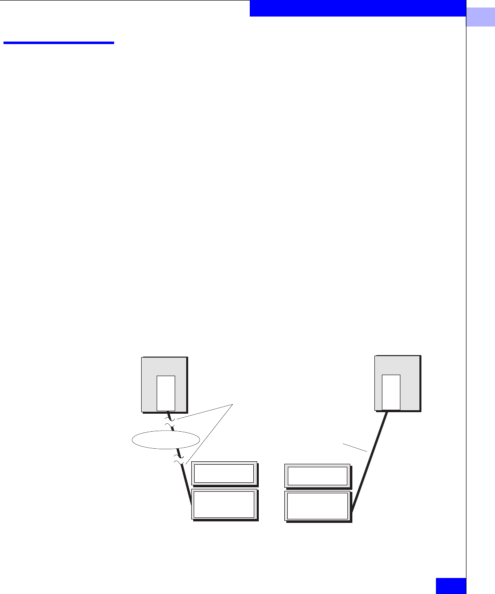
5
Cable and Configuration Guidelines
5-21
Storage System Hardware
Cable and Configuration Guidelines
We recommend that all copper-interconnected nodes be connected to
a common ground grid. The common grid is not needed for optical
interconnections.
Copper cable allows up to 30 meters (99 feet) between nodes or
switches and hubs. Optical cable allows significantly longer
distances. This is a major advantage of optical cable. However, you
can use optical cable from a server only if the server’s adapter
supports optical cable; otherwise you must use copper. Not all
adapters support optical cable.
To connect a DPE to a DAE, you must use copper cable, whose
maximum length is 10 meters (33 ft). So, the distance between a DPE
and the DAEs it controls cannot exceed 10 meters (33 ft).
The host-bus adapters and SPs used with shared storage systems
require optical cable, as does the switch between adapters and SPs.
The SPs used with unshared storage systems support copper cables
and — with MIAs — optical cables. A hub itself supports copper, or
with a MIA, optical. So you can use a copper cable or — with two
MIAs per cable — optical cable between any hub and SP. For optical
cable to work between an adapter and hub or SP, then the adapter
must support optical cable.
Figure 5-10 Comparison Between Optical and Copper Cabling
Server Server
Maximum distance:
Copper cable: 30 m
Adapter
Switch or hub
Storage system
Adapter
Storage system
Maximum distance:
Copper cable: 30 m
Optical cable:500 m
or more

5
5-22
EMC Fibre Channel Storage Systems Configuration Planning Guide
Storage System Hardware
You can use any existing FDDI, multimode, 62.5 micron cable with
good connections to attach servers, switches or hubs, and storage
systems. These cables must be dedicated to storage-system I/O.
Table 5-3 Cable Sizes — Optical
Length Typical Use
5 m (16.5 ft) or
10 m (33 ft)
Within one room, connecting servers to storage systems (adapter
must support optical cable) or connecting switches or hubs to storage
systems
50 m (164 ft) Within one building, connecting servers to storage systems (adapter
must support optical cable) or connecting switches or hubs to storage
systems
100 m (328 ft) Within one complex, connecting servers to storage systems (adapter
must support optical cable) or connecting switches or hubs to storage
systems
250 m (821 ft,.15 mi)
500 m (1642 ft,.31 mi)
Optical cabling is 50 micron (maximum length is 500 m —1,650 ft —, or
62.5 micron (maximum length is 300 m — 985 ft. Both types are multimode, dual SC, and require a MIA on
a DB-9 or hub connector. The minimum length is 2 m (6.8 ft). The minimum bend radius is 3 cm (1.2 in).

5
Cable and Configuration Guidelines
5-23
Storage System Hardware
Table 5-4 Cable Sizes — Copper
Component planning diagrams and worksheets follow.
Length Typical Use
0.3 m (1 ft), non-equalized Connecting DPE/DAE and DAE LCCs
1.0 m (3.3 ft), non-equalized Connecting a hub to an adjacent storage system
3 m (10 ft), non-equalized Connecting a hub to a storage system in the same cabinet, or daisy
chaining from one cabinet to an adjacent cabinet
5 m (16.5 ft), non-equalized Connecting a hub in one rack to a storage system in another cabinet
10 (33 ft), non-equalized Connecting servers to hubs and/or storage systems — maximum
length for non-equalized copper cable, maximum length between LCCs
30 m (98.5 ft), equalized Connecting servers to hubs and/or storage systems – maximum length
for copper cable
Copper cabling is shielded, 75-ohm twin-axial, shield bonded to DB-9 plug connector shell (360o) FC-AL
Standard, Revision 4.4 or higher.
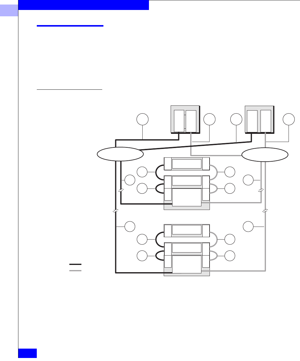
5
5-24
EMC Fibre Channel Storage Systems Configuration Planning Guide
Storage System Hardware
Hardware Planning Worksheets
Following are worksheets to note the hardware components you
want. There are two types of configuration:
•Shared storage
•Unshared storage
Hardware for Shared Storage
Figure 5-11 Cable Identifier — DPE-Based System for Shared Storage
The cable identifiers used above apply to shared and unshared
storage systems. The worksheet applies to shared storage only.
Switch 2
Switch 1
Adapter
Adapter
Adapter
Adapter
LCC LCC LCC
LCC LCC LCC
DAE
DAE
DPE
SP A
SP B
LCC LCC LCC
LCC LCC LCC
DAE
DAE
DPE
SP A
SP B
Path 2
Path 1
. . .
Server 1 Server n
Storage system m
Storage system 1
AnAnA1A1
D1
Dm
D1
Dm
E2
E1
E2
E1
E2
E1
E2
E1

5
Hardware Planning Worksheets
5-25
Storage System Hardware
Hardware Component Worksheet for Shared Storage
Number of servers:____ Adapters in servers:____ Switches: 16-port:____8-port:____
Rackmount DPEs:_____SP/LCC pairs:_____PSs:_____SPSs:____ Rackmount cabinets:___
Rackmount DAEs:_____ LCCs:_____PSs:_____
Cables between server and switch - Cable A, optical only
Cable A1, Optical: Number:____ ....................................................... ..............Length________m or ft
Cable A2, Optical: Number:____ ....................................................... ..............Length________m or ft
Cable An, Optical: Number:____ ...................................................... ..............Length________m or ft
Cables between switches and storage systems - Cable D, copper or optical
Cable D1, Optical:Number:_____ ...................................................... ..............Length________m or ft
Cable D2, Optical:Number:_____ ...................................................... ..............Length________m or ft
Cable Dm, Optical:Number:_____ ..................................................... ..............Length________m or ft
Cables between enclosures - Cable E, which connects LCCs; between a DPE LCC and a DAE LCC, Cable
E must be copper; between DAE LCCs, it can be copper or optical.
Cable E1:Number:_____ VCopper VOptical(for DAE to DAE only). ..............Length________m or ft
Cable E2:Number:_____ VCopper VOptical(for DAE to DAE only) ..............Length________m or ft
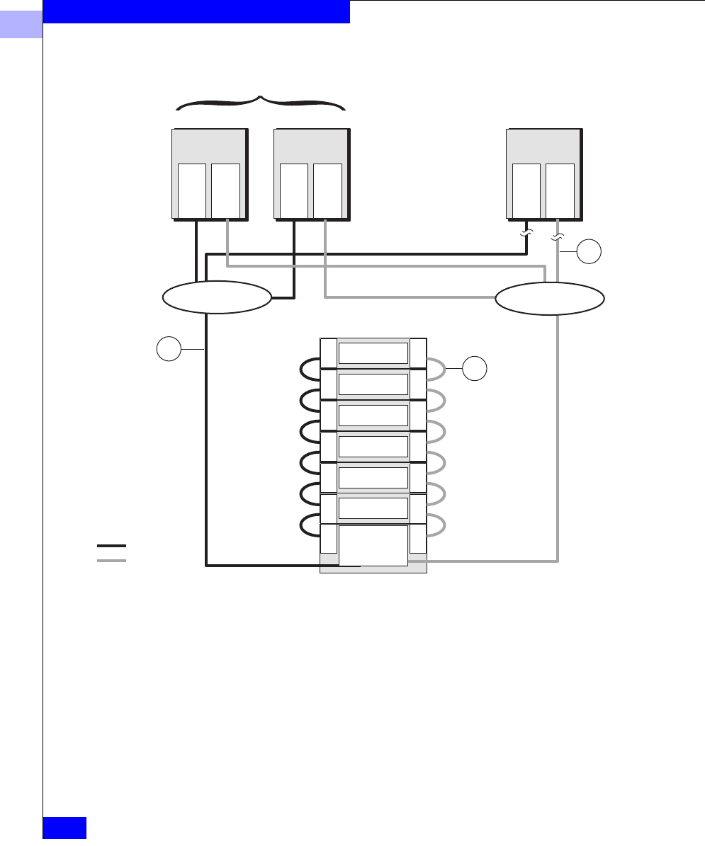
5
5-26
EMC Fibre Channel Storage Systems Configuration Planning Guide
Storage System Hardware
Figure 5-12 Sample Shared Storage Installation
Switch 2
Switch 1
LCC
LCC
DAE
LCC
LCC
DAE
LCC
LCC
DAE
LCC
LCC
DAE
LCC
LCC
DAE
LCC LCC
LCC LCC
DAE
DPE
SP A
SP B
Path 2
Path 1
Storage system
Highly available cluster
Cable between
storage systems
or enclosures
Cable between
server and
switch
Cable between
switch and
storage system
Adapter
Adapter
Mail ServerFile Server
Adapter
Adapter
Database Server
Adapter
Adapter
D1
E1
A2
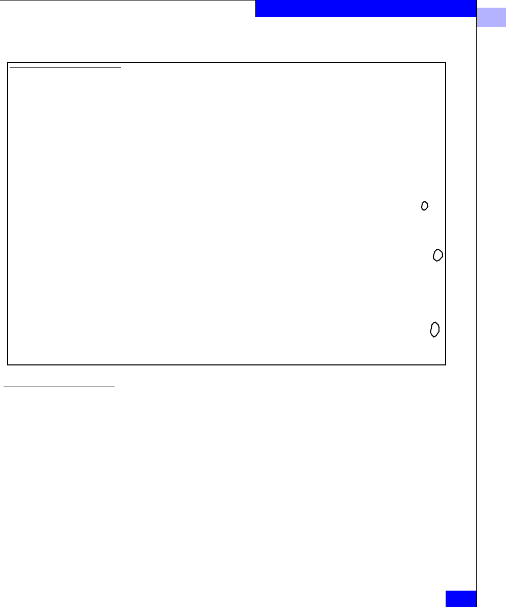
5
Hardware Planning Worksheets
5-27
Storage System Hardware
Hardware for Unshared Storage
The cable identifiers used in the following figure and on the
following worksheets apply to all types of unshared storage systems.
So, if you want to plan a site with different types of systems, you can
consolidate all your unshared storage component entries (from the
different system types on a single worksheet).
Hardware Component Worksheet for Shared Storage
Number of servers:__3_ Adapters in servers:__6_ Switches: 16-port:____8-port:__
2
Rackmount DPEs:__
1
___SP/LCC pairs:__
2
___PSs:___
2
__SPSs:__
2
__ Rackmount cabinets:_
1
__
Rackmount DAEs:__
6
___ LCCs:___
1
2
__PSs:___
1
2
__
Cables between server and switch - Cable A, optical only
Cable A1, Optical: Number:_____ ...................................................... .............Length______m or ft
Cable A2, Optical: Number:__4__ ..................................................... .............Length__
33
_m or ft
Cable An, Optical: Number:____ ....................................................... .............Length______m or ft
Cables between switches and storage systems - Cable D, copper or optical
Cable D1, Optical:Number:__
2
___ .................................................... .............Length___
33
__m or ft
Cable D2, Optical:Number:_____ ...................................................... ............. Length________m or ft
Cable Dm, Optical:Number:_____ ...................................................... .............Length________m or ft
Cables between enclosures - Cable E, which connects LCCs; between a DPE LCC and a DAE LCC, Cable
E must be copper; between DAE LCCs, it can be copper or optical.
Cable E1:Number:__
12
___ VCopper VOptical(for DAE to DAE only) .........Length____
1
___m or ft
Cable E2:Number:_____ VCopper VOptical(for DAE to DAE only). .............Length________m or ft
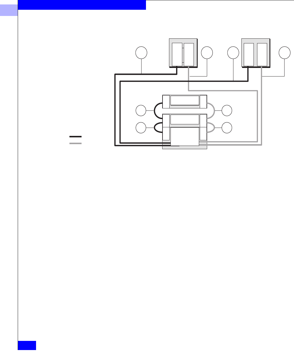
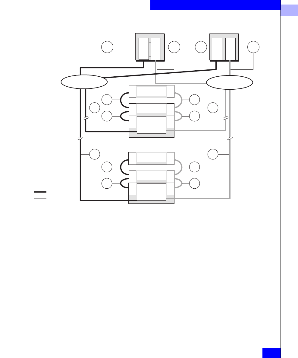
5
Hardware Planning Worksheets
5-29
Storage System Hardware
Figure 5-14 Cable Identifier — Unshared Full-Fibre System with Hubs
Hub 2
Hub 1
Adapter
Adapter
Adapter
Adapter
LCC LCC LCC
LCC LCC LCC
DAE
DAE
iDAE/DPE
SP A
SP B
LCC LCC LCC
LCC LCC LCC
DAE
DAE
iDAE/DPE
SP A
SP B
FC Loop 2
FC Loop 1
. . .
Server 1 Server n
Storage system m
Storage system 1
AnAnA1A1
D1
Dm
D1
Dm
E2
E1
E2
E1
E2
E1
E2
E1

5
5-30
EMC Fibre Channel Storage Systems Configuration Planning Guide
Storage System Hardware
Hardware Component Worksheet for Unshared Storage
Number of servers: Adapters in servers:______ Hubs (copper):_____ MIAs (copper to optical):______
DPE-based and DAE-only storage systems:
Rackmount DPEs:_____SP/LCC pairs:_____ PSs:_____SPSs:____ Rackmount cabinets:___
Rackmount iDAEs:_____SPs:_____ PSs:_____SPSs:____ Rackmount cabinets:___
Rackmount DAEs:_____ LCCs:_____PSs:_____
Deskside DPEs:_____SP/ LCC pairs:_____DAE LCCs:____ DPE PSs:____ DAE PSs:____ SPSs:__
Deskside iDAEs:_____SPs:_____ DAE LCCs:____ PSs:____ SPSs:___
Deskside DAEs: 30-slot_____ 10-slot______ LCCs:_____ PSs:_____
Cables between server and storage system or between server and hub - Cable A, copper or optical
Cable A1:Number:____ VCopper VOptical ...................................... .............Length________m or ft
Cable A2:Number:____ VCopper VOptical..................................... .............Length________m or ft
Cable An:Number:____ VCopper VOptical..................................... .............Length________m or ft
Cables between hubs and storage systems - Cable D, copper or optical
Cable D1:Number:_____ VCopper VOptical ..................................... .............Length________m or ft
Cable D2:Number:_____ VCopper VOptical ..................................... .............Length________m or ft
Cable Dm:Number:_____ VCopper VOptical..................................... .............Length________m or ft
Cables between storage systems or enclosures - Cable E, which connects LCCs or SP-LCC; between a
DPE LCC or iDAE SP and a DAE LCC, Cable E must be copper; between DAE LCCs, it can be copper or
optical.
Cable E1:Number:_____ VCopper VOptical(DAE to DAE only)........ .............Length________m or ft
Cable E2:Number:_____ VCopper VOptical(DAE to DAE only)........ .............Length________m or ft
*Please specify all storage-system components you need, even though you will not need to order them
separately, since most or all components will be included with the model of each system you order.
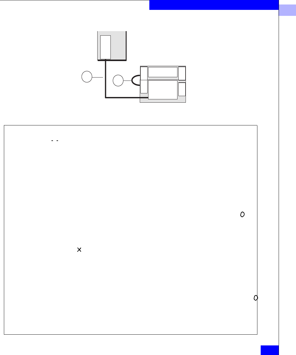
5
Hardware Planning Worksheets
5-31
Storage System Hardware
Figure 5-15 Sample Unshared Deskside System — Basic Configuration
Sample Component Worksheet
A1 Cable between server
and storage system
E1 Cable between storage
systems or enclosures
Included with deskside
DPE
Adapter
LCC LCC
DAE
iDAE/DPE
SP A
Server
E1
A1
Hardware Component Worksheet for Unshared Storage
Number of servers: 1Adapters in servers:___1___ Hubs (copper):______ MIAs (copper to optical):_____
DPE-based and DAE-only storage systems:
Rackmount DPEs:_____SP/LCC pairs:_____ PSs:_____SPSs:____ Rackmount cabinets:___
Rackmount iDAEs:__1___SPs:__1___ PSs:___1__SPSs:____ Rackmount cabinets:__1_
Rackmount DAEs:___1__ LCCs:__1___PSs:__1___
Deskside DPEs:_____SP/ LCC pairs:_____DAE LCCs:____ DPE PSs:____ DAE PSs:____ SPSs:__
Deskside iDAEs:_____SPs:_____ DAE LCCs:____ PSs:____ SPSs:___
Deskside DAEs: 30-slot_____ 10-slot______ LCCs:_____ PSs:_____
Cables between server and storage system or between server and hub - Cable A, copper or optical
Cable A1:Number:__
1
__ VCopper VOptical ................................... ..............Length__
1
0__ _m or ft
Cable A2:Number:____ VCopper VOptical .................................... ..............Length________m or ft
Cable An:Number:____ VCopper VOptical .................................... ..............Length________m or ft
Cables between hubs and storage systems - Cable D, copper or optical
Cable D1:Number:_____ VCopper VOptical..................................... ..............Length________m or ft
Cable D2:Number:_____ VCopper VOptical..................................... ..............Length________m or ft
Cable Dm:Number:_____ VCopper VOptical .................................... ..............Length________m or ft
Cables between storage systems or enclosures - Cable E, which connects LCCs or SP-LCC; between a
DPE LCC or iDAE SP and a DAE LCC, Cable E must be copper; between DAE LCCs, it can be copper or
optical.
Cable E1:Number:__
1
__ VCopper VOptical(DAE to DAE only)....... ..............Length__
1
_____m or ft
Cable E2:Number:_____ VCopper VOptical(DAE to DAE only) .....Length________m or ft
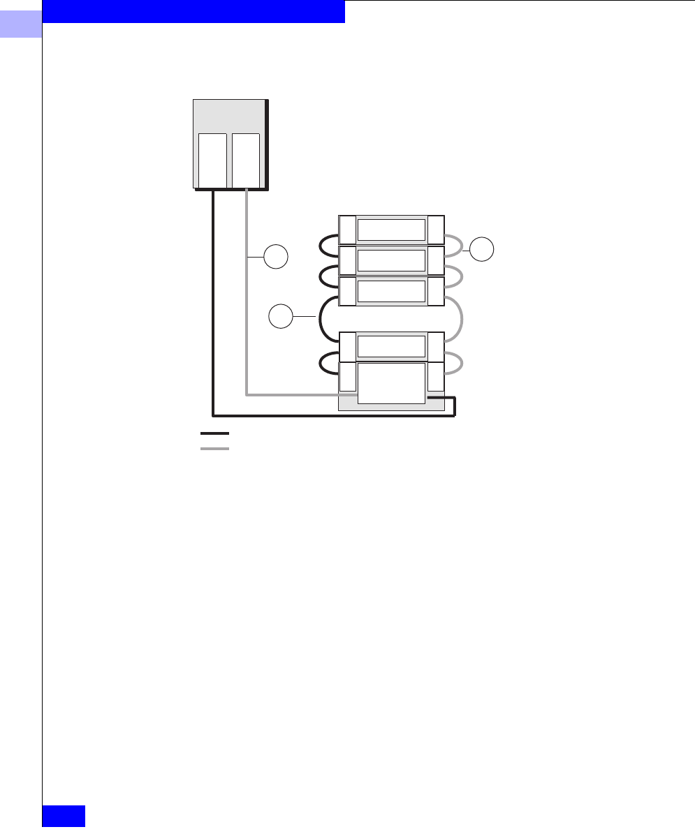
5
5-32
EMC Fibre Channel Storage Systems Configuration Planning Guide
Storage System Hardware
Figure 5-16 Sample Unshared Deskside System — Dual-Adapter/Dual-SP
Configuration
LCC
LCC
DAE
LCC
LCC
DAE
LCC
LCC
DAE
LCC LCC
LCC LCC
DAE
DPE
SP A
SP B
FC Loop 2
FC Loop 1 Storage system
E1 Cable between storage
systems or enclosures
included with deskside DPE
A1 Cable between
server and storage
system
E2 Cable between storage
systems or enclosures
Server
Adapter
Adapter
E2
E1
A1
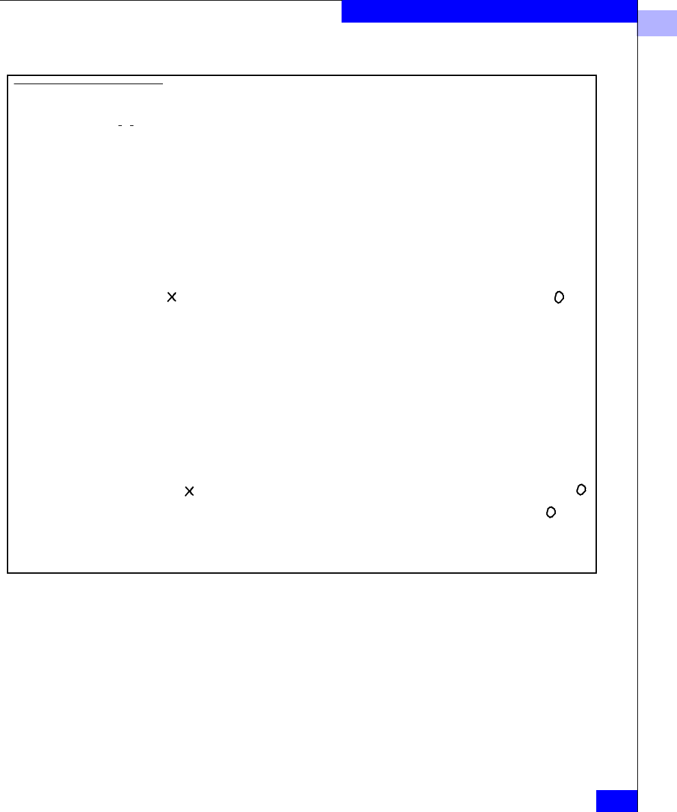
5
Hardware Planning Worksheets
5-33
Storage System Hardware
Sample Component Worksheet
Hardware Component Worksheet for Unshared Storage
Number of servers: 1Adapters in servers:__
2
__ Hubs (copper):______ MIAs (copper to optical):_______
DPE-based and DAE-only storage systems:
Rackmount DPEs:_____SP/LCC pairs:_____ PSs:_____SPSs:____ Rackmount cabinets:___
Rackmount iDAEs:_____SPs:_____ PSs:_____SPSs:____ Rackmount cabinets:___
Rackmount DAEs:_____ LCCs:_____PSs:_____
Deskside DPEs:__
1
_SP/ LCC pairs:__
2
__DAE LCCs:__
2
__ DPE PSs:_
2
_ DAE PSs:_
2
_ SPSs:_1_
Deskside iDAEs:_____SPs:_____ DAE LCCs:____ PSs:____ SPSs:___
Deskside DAEs: 30-slot__1___ 10-slot______ LCCs:__6___ PSs:__6__
Cables between server and storage system or between server and hub - Cable A, copper or optical
Cable A1:Number:_
2
_VCopper VOptical ...................................... ............. Length___
1
0
___m or ft
Cable A2:Number:____ VCopper VOptical .................................... ............. Length________m or ft
Cable An:Number:____ VCopper VOptical .................................... ............. Length________m or ft
Cables between hubs and storage systems - Cable D, copper or optical
Cable D1:Number:_____ VCopper VOptical..................................... ............. Length________m or ft
Cable D2:Number:_____ VCopper VOptical..................................... ............. Length________m or ft
Cable Dm:Number:_____ VCopper VOptical .................................... ............. Length________m or ft
Cables between storage systems or enclosures - Cable E, which connects LCCs or SP-LCC; between a
DPE LCC or iDAE SP and a DAE LCC, Cable E must be copper; between DAE LCCs, it can be copper or
optical.
Cable E1:Number:__6___ VCopper VOptical(DAE to DAE only)...... ............. Length___1____m or ft
Cable E2:Number:__
2
___ VCopper VOptical(DAE to DAE only)...... ............. Length___5____m or ft
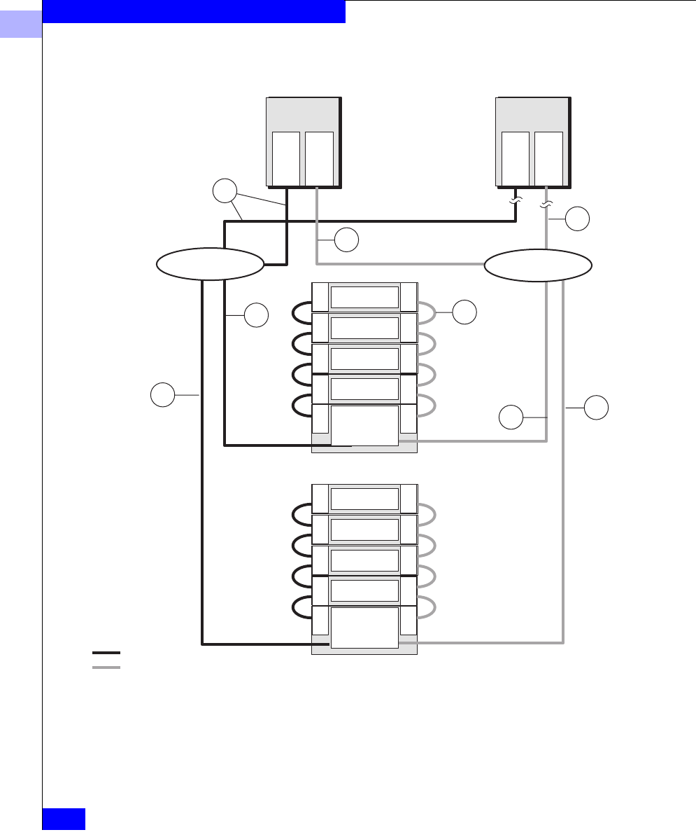
5
5-34
EMC Fibre Channel Storage Systems Configuration Planning Guide
Storage System Hardware
Figure 5-17 Sample Component Worksheet for DPE-Based System with Hubs — Two
Loops
Hub 2
Hub 1
LCC
LCC
DAE
LCC
LCC
DAE
LCC
LCC
DAE
LCC LCC
LCC LCC
DAE
DPE
SP A
SP B
LCC
LCC
DAE
LCC
LCC
DAE
LCC
LCC
DAE
LCC LCC
LCC LCC
DAE
DPE
SP A
SP B
FC Loop 2
FC Loop 1
Storage system 1
Storage system 2
Cable between
storage systems
or enclosures
Cable between
server and hub
Cable between
server and hub
Cable between
hub and storage
system
Adapter
Adapter
Server 1
Adapter
Adapter
Server 2
D1
D2
Cable between
hub and storage
system
D1
D2
E1
A2
A2
A1
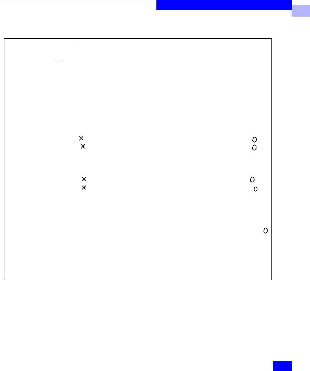
5
Hardware Planning Worksheets
5-35
Storage System Hardware
What Next? This chapter explained hardware components of shared and
unshared storage systems. If you have completed the worksheets to
your satisfaction, you are ready to consider ordering some of this
equipment. Or you may want to read about storage management in
the next chapter.
Hardware Component Worksheet for Unshared Storage
Number of servers:
2
Adapters in servers:___4____ Hubs:___
2
____ MIAs (optical to copper):_______
DPE-based and DAE-only storage systems:
Rackmount DPEs:_____SP/LCC pairs:__4___ PSs:___4__SPSs:_
2
__ Rackmount cabinets:_
2
__
Rackmount iDAEs:_____SPs:_____ PSs:_____SPSs:____ Rackmount cabinets:___
Rackmount DAEs:__ 8 ___ LCCs:__16_PSs:__16___
Deskside DPEs:_____SP/ LCC pairs:_____DAE LCCs:____ DPE PSs:____ DAE PSs:____ SPSs:__
Deskside iDAEs:_____SPs:_____ DAE LCCs:____ PSs:____ SPSs:___
Deskside DAEs: 30-slot_____ 10-slot______ LCCs:_____ PSs:_____
Cables between server and storage system or between server and hub - Cable A, copper or optical
Cable A1:Number:__
2
_VCopper VOptical..................................... ..............Length_
2
0
_____m or ft
Cable A2:Number:__
2
__ VCopper VOptical ................................. ..............Length_1
0
_____m or ft
Cable An:Number:____ VCopper VOptical.................................... ..............Length________m or ft
Cables between hubs and storage systems - Cable D, copper or optical
Cable D1:Number:__
2
__ VCopper VOptical.................................... ..............Length__
2
0
__ _m or ft
Cable D2:Number:__
2
__ VCopper VOptical.................................... ..............Length___
2
0
___m or ft
Cable Dm:Number:_____ VCopper VOptical.................................... ..............Length________m or ft
Cables between storage systems or enclosures - Cable E, which connects LCCs or SP-LCC; between a
DPE LCC or iDAE SP and a DAE LCC, Cable E must be copper; between DAE LCCs, it can be copper or
optical.
Cable E1:Number:_16__ VCopper VOptical(DAE to DAE only)....... ..............Length___1____m or ft
Cable E2:Number:_____ VCopper VOptical(DAE to DAE only)....... ..............Length________m or ft
Please specify all storage-system components you need, even though you will not need to order them
separately, since most or all components will be included with the model of each system you order.


Storage-System Management
6-1
6
This chapter explains the management applications you can use to
manage storage systems from servers. Topics are
•Using Navisphere Manager Software.............................................6-3
•Storage Management Worksheets ...................................................6-5
Storage-System
Management

6
6-2
EMC Fibre Channel Storage-System Configuration Planning
Storage-System Management
Navisphere software lets you bind and unbind disks, manipulate
caches, examine storage-system status and logged events, transfer
control from one SP to another, and examine events recorded in
storage system event logs.
Navisphere products have two parts: a graphical user interface (GUI)
and an Agent application. The GUIs run on a management station,
accessible from a common framework, and communicate with
storage systems through the Agent that runs on each server. The
Navisphere products are
•Navisphere Manager, which lets you manage multiple storage
systems on multiple servers simultaneously;
•Navisphere Analyzer, which lets you measure, compare, and
chart the performance of SPs, LUNs, and disks.
•Navisphere Integrator, which provides an interface between
Navisphere products and HP OpenView, CA Unicenter, and
Tivoli.
•Navisphere Event Monitor, which checks storage systems for
fault conditions and can notify you and/or customer service if
any fault condition occurs.
•Navisphere failover software. Application-Transparent Failover
(ATF) is an optional software package for high-availability
installations. ATF software lets applications continue running
after the failure anywhere in the path to a LUN: a host-bus
adapter, cable, switch, or SP. ATF is required for any server that
has two host-bus adapters connected to the same storage system.
Another failover product is CDE (Driver Extensions) software,
which has limited failover features. CDE is included with each
host-bus adapter driver package.
•Navisphere Agent, which is included with each storage system,
and Navisphere CLI (Command Line Interface), which lets you
bypass the GUI and type commands directly to storage systems.
The Agent runs on any of several different platforms, including
Windows and popular UNIX® platforms; the other products run on
Windows platforms only.

6
Using Navisphere Manager Software
6-3
Storage-System Management
Using Navisphere Manager Software
Navisphere Manager software (Manager) lets you manage multiple
storage systems connected to servers on a TCP/IP network. Manager
offers extensive management features and includes comprehensive
on-line help. Manager is required for shared storage and optional for
unshared storage.
Manager runs on a management station which is a Windows NT® or
Windows® 2000 host. The servers connected to a storage system can
run Windows or one of several UNIX® operating systems. With
shared storage, servers connected to the SAN can run different
operating systems; with direct (unshared direct or
shared-or-clustered) storage, servers connected to the same storage
system must run the same operating system.
The following figures show Navisphere Manager in shared and
unshared environments.
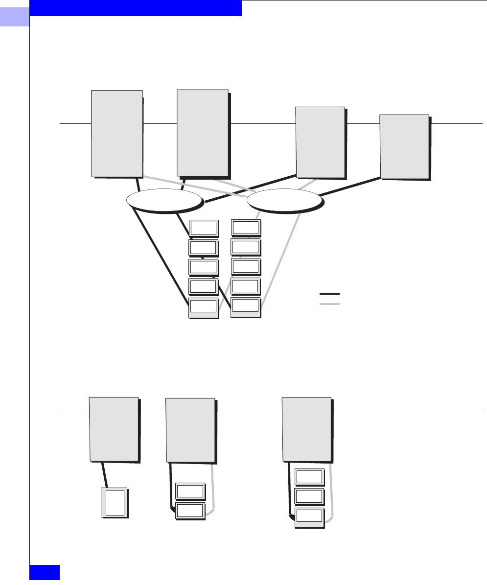
6
6-4
EMC Fibre Channel Storage-System Configuration Planning
Storage-System Management
Figure 6-1 Sample Shared Switched Environment with Navisphere Manager
Figure 6-2 Sample Unshared Environment with Navisphere Manager
File Server
Management
station and server
Mail Server
Management
station and server Database Server
Switch fabric Switch fabric
Production Server
LAN
Navisphere
Manager
Navisphere
Agent
Failover
software
Operating
system A Operating
system B
Navisphere
Agent
Failover
software
Operating
system C
Navisphere
Agent
Failover
software
Navisphere
Manager
Navisphere
Agent
Failover
software
Operating
system A
Path 2
Path 1
Accts Server
Management
station and server
Development Server
Management
station and server
Database Server
Operating
system A
Navisphere
Supervisor
Navisphere
Agent
Operating
system B
Navisphere
Agent
Operating
system C
Navisphere
Agent
LAN
Navisphere
Supervisor

6
Storage Management Worksheets
6-5
Storage-System Management
Storage Management Worksheets
This section includes two worksheets: one for shared storage and one
for unshared storage. The following worksheet will help you plan
your storage system management environment. For each host,
complete a section.
For the shared storage worksheet, complete the management station
hostname and operating system; then decide whether you want the
Navisphere Analyzer and/or Event Monitor and, if so, mark the
appropriate boxes. Then write the name of each managed server, with
operating system, Storage Group, and configuration access
specification. You can copy much of the needed information from the
LUN and Storage Group planning worksheet in Chapter 3 or 4.
Management Utility Worksheet – Shared Storage
Management station hostname:___________________Operating system:_______________
Software: V Navisphere Manager/Agent V Navisphere Analyzer VNavisphere Event Monitor
List all the servers this host will manage. Each managed server must run an Agent and ATF software
of the same type as its operating system.
Server: Op sys: Storage Group number or name: VConfig Access
Server: Op sys: Storage Group number or name: VConfig Access
Server: Op sys: Storage Group number or name: VConfig Access
Server: Op sys: Storage Group number or name: VConfig Access
Server: Op sys: Storage Group number or name: VConfig Access
Server: Op sys: Storage Group number or name: VConfig Access
Server: Op sys: Storage Group number or name: VConfig Access
Server: Op sys: Storage Group number or name: VConfig Access

6
6-6
EMC Fibre Channel Storage-System Configuration Planning
Storage-System Management
For unshared storage (unshared direct or shared-or-clustered direct),
for each host, choose a Navisphere product. The host may be a
management station that is not a server (complete only the Manager
section); it may be a management station that is a server (complete
the Manager section and mark the Agent box), or it may be a server
(mark the Agent box).

6
Storage Management Worksheets
6-7
Storage-System Management
Management Utility Worksheet – Unshared Storage
Hostname: Operating system:
Storage system type: VDPE-based ViDAE-based
Software: V Navisphere Manager/Agent VNavisphere Analyzer VNavisphere Event Monitor
List all the servers this host will manage. Each managed server must run an Agent of the same type
as its operating system.
Server: Oper sys: Server: Oper sys:
Server: Oper sys: Server: Oper sys:
Server: Oper sys: Server: Oper sys:
Server: Oper sys: Server: Oper sys:
Hostname: Operating system:
Storage system type: VDPE-based ViDAE-based
Software: V Navisphere Manager and Navisphere Agent VNavisphere Agent and CLI
List all the servers this host will manage. Each managed server must run an Agent of the same type
as its operating system.
Server: Oper sys: Server: Oper sys:
Server: Oper sys: Server: Oper sys:
Server: Oper sys: Server: Oper sys:
Server: Oper sys: Server: Oper sys:
Hostname: Operating system:
Storage system type: VDPE-based ViDAE-based
Software: V Navisphere Manager and Navisphere Agent V Navisphere Agent and CLI
List all the servers this host will manage. Each managed server must run an Agent of the same type
as its operating system.
Server: Oper sys: Server: Oper sys:
Server: Oper sys: Server: Oper sys:
Server: Oper sys: Server: Oper sys:
Server: Oper sys: Server: Oper sys:

6
6-8
EMC Fibre Channel Storage-System Configuration Planning
Storage-System Management

EMC Fibre Channel Storage Systems Configuration Planning Guide
i-1
A
ac power requirements
DAE-only storage system 5-18
DPE storage system 5-14
iDAE storage system 5-16
application planning
shared storage 3-6
unshared storage 4-4
application worksheet, completing
shared 3-6, 4-4
unshared or clustered direct 4-4
applications
for RAID Groups, sample 2-19
LUN and file system
planning 3-6
application-transparent failover (ATF) software
6-2
array, see disk-array storage system
attach kit, see host-bus adapter driver package
audience for manual xi
C
cabinets for rackmount storage systems 5-20
cabling
guidelines 5-21
introduced 1-4
types and sizes 5-22
cache
about 5-11
page size 4-13
cascading switches 1-6
CDE driver extensions software 6-2
CLI (Command Line Interface) 6-2
clustered installation, disk structure example 4-3
communication with storage system, see Chapter
6
configurations
RAID
compared 2-12
examples 4-2
planning 3-6
RAID types
guidelines 2-17
shared storage
examples 3-3
tradeoffs 5-12
unshared storage
examples 4-2
installation 4-2
cooling requirements
cabinet 5-20
DAE 5-19
DPE 5-15
iDAE 5-17
copper cable, types and sizes 5-23
CRUs (customer-replaceable units)
DPE storage system 5-5
locating 5-8
SP 5-5, 5-9
D
DAE, see also Disk Array Enclosure (DAE)
DAE-only storage systems
dimensions 5-18
introduced 1-16, 5-6
Index

EMC Fibre Channel Storage Systems Configuration Planning Guide
i-2
Index
site requirements 5-18
weight 5-18
data sheets, hardware 5-14
device name, operating system 3-16, 4-15
disk
capacity
defined 4-14
capacity, defined 4-13
configuration types
compared 2-12
configuration, see also RAID Group
IDs 3-4, 4-2
LUN types
planning 3-6
mirror, defined 2-2
number on worksheet 4-14
RAID types
guidelines 2-17
sample applications 2-19
shared storage
examples 3-3
striping, defined 2-2
unit number on worksheet 3-8, 4-13
unshared storage
example 4-2
examples 4-2
Disk Array Enclosure (DAE)
introduced 5-6
site requirements 5-18
Disk Array Processor Enclosure (DPE)
introduced 5-6
Disk Array Processor Enclosure (DPE), see DPE
storage system
disk-array storage system
communicating with, see Chapter 6
hardware
shared storage 1-15
unshared storage 1-16
installation types 1-10
managing, see Chapter 6
DPE storage systems
components 5-3
dimensions 5-14
site requirements 5-14
weight 5-14
driver extensions software (CDE) 6-2
dual paths to LUNs 3-2, 4-2
E
enclosure address (EA)
DPE 5-4, 5-8
F
fabric, switch
introduced 1-3
Fibre Channel
adapter 1-4
components 1-4
defined 1-3
hub, description 1-8
switch, description 1-5
switch, see switch
file system
name 3-17, 4-15
worksheet
completing 3-13, 4-12
footprint
DAE-only storage system 5-18
DPE storage systems 5-14
iDAE storage systems 5-16
rackmount cabinet 5-20
G
GBIC (Gigabit Interface Converter), about 1-5
global spare, see hot spare
grounding requirements 5-21
GUI (in storage-system management utilities) 6-3
H
hardware
data sheets 5-14
mirroring 2-2
planning worksheets
shared storage 5-24
shared storage 1-15, 5-3
unshared storage 1-16
heat dissipation
DAE-only storage system 5-18
DPE storage system 5-14
iDAE storage system 5-16
height
DAE-only storage systems 5-18
DPE storage system 5-14

i-3
EMC Fibre Channel Storage Systems Configuration Planning Guide
Index
iDAEstorage system 5-16
high availability
options for unshared storage 5-13
shared switched instllation 1-10
host, see also server
host-bus adapter (HBA), introduced 1-4
host-bus adapter driver package 1-4
hot spare
defined 2-9
sample applications 2-20
when to use 2-18
hub
description 1-8
planning system with 5-29
sample hardware worksheet 5-34
I
iDAE storage systems
dimensions 5-16
site requirements 5-16
weight 5-16
image, disk, defined 2-2
individual access array, see RAID 5 Group
individual disk unit
defined 2-9
disk space usage 2-16
performance 2-14
sample applications 2-20
when to use 2-18
installation types 1-10
tradeoffs 5-11
intelligent Disk Array Enclosure (iDAE), see
iDAE storage systems
interconnect components 5-1
cables, hubs, switches 1-4
interface kit, see host-bus adapter driver package
L
LCC (link control card) 5-8
logical volume, see file system
LUN (logical unit)
configurations
individual disk, defined 2-9
RAID 0, defined 2-8
RAID 1 mirrored pair 2-7
RAID 1/0 Group
defined 2-8
RAID 3 Group, defined 2-5
RAID 5 Group, defined 2-4
shared storage, examples 3-3
disk mirror, defined 2-2
in RAID Group 2-3
number on worksheet 3-8, 3-15, 4-13, 4-14
paths to 3-2, 4-2
planning 3-6
RAID types
compared 2-12
guidelines 2-17
sample applications 2-19
SP control of 5-10
unshared storage
examples 4-2
unshared, examples 4-2
worksheets 3-13, 4-10, 4-12
M
Manager utility 6-2
manual, about 1-xi
MIA (media interface adapter), about 1-5
mirrored pair, see RAID 1 mirrored pair
mirrored RAID 0 Group, see RAID 1/0 Group
mirroring, defined 2-2
N
Navisphere Manager utility 6-2
node, defined 1-3
nonredundant array, see also RAID 0 Group
O
operating system
device name for disk unit 4-15
device name for LUN 3-16
software mirroring 2-2
optical cable, types and sizes 5-22
organization of manual xii

EMC Fibre Channel Storage Systems Configuration Planning Guide
i-4
Index
P
page size, cache 3-14, 4-13
parallel access array, see RAID 3 Group
paths to LUNs 3-2, 4-2
performance, RAID Group 2-13
physical disk unit, see LUN (logical unit)
physical volume, see LUN (logical unit)
planning LUNs and file systems 3-6
plant requirements
DAE 5-18
iDAE 5-16
plug types 5-20
power requirements
DAE-only storage system 5-18
DPEstorage system 5-14
iDAE storage system 5-16
power supplies (PSs), DPE storage system 5-8
R
rackmount model DPE storage system
DPE storage system
rackmount model 5-3
RAID Group
configurations
compared 2-12
performance 2-13
planning 3-6
RAID types
guidelines 2-17
sample applications 2-19
RAID 3 versus RAID 5 2-6
shared storage
examples 3-3
types and tradeoffs, see Chapter 2
unshared storage
examples 4-2
RAID Groups and LUNs 2-3
RAID types
guidelines 2-17
sample applications 2-19
RAID 0 Group
defined 2-8
sample applications 2-20
when to use 2-18
RAID 1 mirrored pair
defined 2-7
sample applications 2-19
when to use 2-17
RAID 1/0 Group
defined 2-8
sample applications 2-20
when to use 2-17
RAID 3 Group
defined 2-5
sample applications 2-19
when to use 2-17
RAID 5 Group
defined 2-4
sample applications 2-19
when to use 2-17
redundant array of independent disks (RAID), see
RAID Group
S
server
cabling guidelines 5-21
component 5-1
connection to storage system, see cabling
planning worksheet
unshared storage 5-30
unshared storage example 4-2
service clearance
DPE storage system 5-15
iDAEstorage system 5-17
shared storage
components 5-3
disk structure example 3-3
hardware 1-15
switched, defined 1-10
shared storage systems
cabinets 5-20
hardware planning worksheets 5-24
shared-or-clustered direct installation
defined 1-10
disk structure example 4-2, 4-3
site requirements
DAE 5-18
DAE-only storage systems 5-18
DPE storage systems 5-14
iDAE storage systems 5-16
size, cache 3-14, 4-13
software mirroring, defined 2-2

i-5
EMC Fibre Channel Storage Systems Configuration Planning Guide
Index
SP (storage processor)
description 5-5, 5-9
FC-AL address ID 3-14, 4-12
SPS (standby power supply)
DPE storage system 5-8
storage components
shared storage 5-3
storage managment worksheets 6-5
storage system
caching
on worksheet 4-14
storage-system caching
as feature 5-11
stripe
with RAID 1/0, RAID 0 2-8
with RAID 5, RAID 3 2-4
stripe, defined 2-2
switch
description 1-5
in sample shared storage configuration 3-3
introduced 1-3
switch fabric
introduced 1-3
T
temperature requirements
DAE-only storage system 5-18
DPE storage system 5-14
iDAE storage system 5-16
terms, RAID 2-2
tradeoffs
installation types 5-11
RAID types 2-12
U
unshared direct installation
defined 1-10
disk structure example 4-2
unshared storage
disk structure example 4-2
hardware 1-16
hardware planning worksheets 5-27
installation types 4-2
V
vault disks 2-10
volume, name 3-17
W
weight
DAE-only storage systems 5-18
DPE storage system 5-14
iDAE storage system 5-16
storage system installation 5-20
worksheet
application 3-6
completing 3-6
component planning
unshared storage 5-29
LUN 3-13, 4-10, 4-11, 4-12
worksheets
component planning
shared storage 5-24
unshared storage 5-27
storage management 6-5

