Emerson Process Management Controlwave Efm 3808 Users Manual Bristol Express RTU (CI Express)
3808 to the manual 3972e561-b036-4db9-927a-093a92e7ba32
2015-02-06
: Emerson-Process-Management Emerson-Process-Management-Controlwave-Efm-3808-Users-Manual-540076 emerson-process-management-controlwave-efm-3808-users-manual-540076 emerson-process-management pdf
Open the PDF directly: View PDF ![]() .
.
Page Count: 182 [warning: Documents this large are best viewed by clicking the View PDF Link!]
www.EmersonProcess.com/Remote
Instruction Manual
CI-ControlWave Express
Feb., 2009
Bristol ControlWave Ex
p
ress
Bristol ControlWave Express
(Remote Terminal Unit)
Remote Automation Solution
s
Click here to return to Table of Contents
IMPORTANT! READ INSTRUCTIONS BEFORE STARTING!
Be sure that these instructions are carefully read and understood before any operation is
attempted. Improper use of this device in some applications may result in damage or injury. The
user is urged to keep this book filed in a convenient location for future reference.
These instructions may not cover all details or variations in equipment or cover every possible
situation to be met in connection with installation, operation or maintenance. Should problems arise
that are not covered sufficiently in the text, the purchaser is advised to contact Emerson Process
Management, Remote Automation Solutions division (RAS) for further information.
EQUIPMENT APPLICATION WARNING
The customer should note that a failure of this instrument or system, for whatever reason, may
leave an operating process without protection. Depending upon the application, this could result in
possible damage to property or injury to persons. It is suggested that the purchaser review the
need for additional backup equipment or provide alternate means of protection such as alarm
devices, output limiting, fail-safe valves, relief valves, emergency shutoffs, emergency switches,
etc. If additional information is required, the purchaser is advised to contact RAS.
RETURNED EQUIPMENT WARNING
When returning any equipment to RAS for repairs or evaluation, please note the following: The
party sending such materials is responsible to ensure that the materials returned to RAS are clean
to safe levels, as such levels are defined and/or determined by applicable federal, state and/or
local law regulations or codes. Such party agrees to indemnify RAS and save RAS harmless from
any liability or damage which RAS may incur or suffer due to such party's failure to so act.
ELECTRICAL GROUNDING
Metal enclosures and exposed metal parts of electrical instruments must be grounded in
accordance with OSHA rules and regulations pertaining to "Design Safety Standards for Electrical
Systems," 29 CFR, Part 1910, Subpart S, dated: April 16, 1981 (OSHA rulings are in agreement
with the National Electrical Code).
The grounding requirement is also applicable to mechanical or pneumatic instruments that
include electrically operated devices such as lights, switches, relays, alarms, or chart drives.
EQUIPMENT DAMAGE FROM ELECTROSTATIC DISCHARGE VOLTAGE
This product contains sensitive electronic components that can be damaged by exposure to an
electrostatic discharge (ESD) voltage. Depending on the magnitude and duration of the ESD, this
can result in erratic operation or complete failure of the equipment. Read supplemental document
S14006 at the back of this manual for proper care and handling of ESD-sensitive components.
Remote Automation Solutions
A Division of Emerson Process Management
1100 Buckingham Street, Watertown, CT 06795
Telephone (860) 945-2200
Click here to return to Table of Contents

WARRANTY
A. Remote Automation Solutions (RAS) warrants that goods described herein and manufactured by RAS are
free from defects in material and workmanship for one year from the date of shipment unless otherwise
agreed to by RAS in writing.
B. RAS warrants that goods repaired by it pursuant to the warranty are free from defects in material and
workmanship for a period to the end of the original warranty or ninety (90) days from the date of delivery of
repaired goods, whichever is longer.
C. Warranties on goods sold by, but not manufactured by RAS are expressly limited to the terms of the
warranties given by the manufacturer of such goods.
D. All warranties are terminated in the event that the goods or systems or any part thereof are (i) misused,
abused or otherwise damaged, (ii) repaired, altered or modified without RAS consent, (iii) not installed,
maintained and operated in strict compliance with instructions furnished by RAS or (iv) worn, injured or
damaged from abnormal or abusive use in service time.
E. These warranties are expressly in lieu of all other warranties express or implied (including without limitation
warranties as to merchantability and fitness for a particular purpose), and no warranties, express or
implied, nor any representations, promises, or statements have been made by RAS unless endorsed
herein in writing. Further, there are no warranties which extend beyond the description of the face hereof.
F. No agent of RAS is authorized to assume any liability for it or to make any written or oral warranties beyond
those set forth herein.
REMEDIES
A. Buyer's sole remedy for breach of any warranty is limited exclusively to repair or replacement without cost
to Buyer of any goods or parts found by Seller to be defective if Buyer notifies RAS in writing of the alleged
defect within ten (10) days of discovery of the alleged defect and within the warranty period stated above,
and if the Buyer returns such goods to the RAS Watertown office, unless the RAS Watertown office
designates a different location, transportation prepaid, within thirty (30) days of the sending of such
notification and which upon examination by RAS proves to be defective in material and workmanship. RAS
is not responsible for any costs of removal, dismantling or reinstallation of allegedly defective or defective
goods. If a Buyer does not wish to ship the product back to RAS, the Buyer can arrange to have a RAS
service person come to the site. The Service person's transportation time and expenses will be for the
account of the Buyer. However, labor for warranty work during normal working hours is not chargeable.
B. Under no circumstances will RAS be liable for incidental or consequential damages resulting from breach
of any agreement relating to items included in this quotation from use of the information herein or from the
purchase or use by Buyer, its employees or other parties of goods sold under said agreement.
Click here to return to Table of Contents

How to return material for Repair or Exchange
Before a product can be returned to Remote Automation Solutions (RAS) for repair, upgrade, exchange, or to verify
proper operation, Form (GBU 13.01) must be completed in order to obtain a RA (Return Authorization) number and
thus ensure an optimal lead time. Completing the form is very important since the information permits the RAS
Watertown Repair Dept. to effectively and efficiently process the repair order.
You can easily obtain a RA number by:
A. FAX
Completing the form (GBU 13.01) and faxing it to (860) 945-2220. A RAS Repair Dept. representative will
return the call (or other requested method) with a RA number.
B. E-MAIL
Accessing the form (GBU 13.01) via the RAS Web site (www.emersonprocess.com/Bristol) and sending it
via E-Mail to Custserve.bristol@emersonprocess.com . A RAS Repair Dept. representative will return E-
Mail (or other requested method) with a RA number.
C. Mail
Mail the form (GBU 13.01) to
Remote Automation Solutions
A Division of Emerson Process Management
Repair Dept.
1100 Buckingham Street
Watertown, CT 06795
A RAS Repair Dept. representative will return call (or other requested method) with a RA number.
D. Phone
Calling the RAS Repair Department at (860) 945-2442. A RAS Repair Department representative will
record a RA number on the form and complete Part I, send the form to the Customer via fax (or other
requested method) for Customer completion of Parts II & III.
A copy of the completed Repair Authorization Form with issued RA number should be included with the product
being returned. This will allow us to quickly track, repair, and return your product to you.
Click here to return to Table of Contents

Remote Automation Solutions (RAS)
Repair Authorization Form (on-line completion)
(Providing this information will permit Bristol, also doing business as Remote Automation Solutions (RAS) to
effectively and efficiently process your return. Completion is required to receive optimal lead time. Lack of information
may result in increased lead times.)
Form GBU 13.01 Rev. D 12/04/07
Date RA # SH Line No.
Standard Repair Practice is as follows: Variations to
this is practice may be requested in the “Special
Requests” section.
• Evaluate / Test / Verify Discrepancy
• Repair / Replace / etc. in accordance with this form
• Return to Customer
Please be aware of the Non warranty standard
charge:
• There is a $100 minimum evaluation charge,
which is applied to the repair if applicable (√ in
“returned” B,C, or D of part III below)
Part I Please complete the following information for single unit or multiple unit returns
Address No. (office use only)
Bill to : Ship to:
Purchase Order: Contact Name:
Phone: Fax: E-Mail:
Part II Please complete Parts II & III for each unit returned
Model No./Part No. Description:
Range/Calibration: S/N:
Reason for return : Failure Upgrade Verify Operation Other
1. Describe the conditions of the failure (Frequency/Intermittent, Physical Damage, Environmental Conditions,
Communication, CPU watchdog, etc.) (Attach a separate sheet if necessary)
2. Comm. interface used: Standalone RS-485 Ethernet Modem (PLM (2W or 4W) or SNW) Other:
3. What is the Firmware revision? What is the Software & version?
Part III If checking “replaced” for any question below, check an alternate option if replacement is not
available
A. If product is within the warranty time period but is excluded due
to the terms of warranty,, would you like the product: repaired returned replaced scrapped?
B. If product were found to exceed the warranty period, would you like the product:
repaired returned replaced scrapped?
C. If product is deemed not repairable would you like your product: returned replaced scrapped?
D. If RAS is unable to verify the discrepancy, would you like the product: returned replaced *see
below?
* Continue investigating by contacting the customer to learn more about the problem experienced? The person
to contact that has the most knowledge of the problem is: phone
If we are unable to contact this person the backup person is: phone
Special Requests:
Ship prepaid to: Remote Automation Solutions, Repair Dept., 1100 Buckingham Street, Watertown, CT 06795
Phone: 860-945-2442 Fax: 860-945-2220
Click here to return to Table of Contents

Emerson Process Management
Training
GET THE MOST FROM YOUR EMERSON
INSTRUMENT OR SYSTEM
• Avoid Delays and problems in getting your system on-line
• Minimize installation, start-up and maintenance costs.
• Make the most effective use of our hardware and software.
• Know your system.
As you know, a well-trained staff is essential to your operation. Emerson offers a full
schedule of classes conducted by full-time, professional instructors. Classes are offered
throughout the year at various locations. By participating in our training, your personnel
can learn how to install, calibrate, configure, program and maintain your Emerson products
and realize the full potential of your system.
For information or to enroll in any class, go to http://www.EmersonProcess.com/Remote and
click on “Training” or contact our training department in Watertown at (860) 945-2343.
Click here to return to Table of Contents

CI-ControlWave Express - Installation Forward
CI-ControlWave Express
ControlWave Express
Remote Terminal Unit
INSTALLATION FORWARD
NOTE for all ControlWave Express Installers:
READ THIS SECTION FIRST!
This manual has been designed for the following audience:
• Customer Site Engineers, who must plan for the installation and implementation of the
ControlWave Express.
• Instructors who must become familiar with and teach Field Engineers/Technicians on
the installation, operation and repair of ControlWave Express.
• Field Engineers/Technicians who must install and service the ControlWave Express.
Installation of the ControlWave Express is provided in two formats as follows:
Section 2 - Installation & Operation provides a detailed overview of the installation and
operation of the ControlWave Express. Section 2 provides all the information required for
instructors who are training individuals unfamiliar with the ControlWave Express. It is
also intended to support anyone who needs to learn how to install and operate the Control-
Wave Express for the first time.
Appendix C - Hardware Installation Guide is intended for individuals who are already
familiar with the ControlWave Express but need the configuration information in a
concise format. Field Engineers/Technicians who have previously installed one or more
ControlWave Express will find the necessary installation information logically sequenced
for their convenience.
NOTE:
A Windows driven diagnostic tool referred to as WINDIAG is provided on the
OpenBSI Software CDROM. WINDIAG is documented in instruction manual
D4041A – Window Diagnostics for Bristol Controllers. Bristol’s WINDIAG program
provides menu driven diagnostics that have been designed to assist a technician
or Process Engineer in troubleshooting the various ControlWave Express
circuits. A brief overview is provided in Section 3.5 of this manual. For more
detailed descriptions of ControlWave Express Windows Diagnostics than those
provided herein, see Document D4041A – Chapters 1 and 7C.
Click here to return to Table of Contents
BLANK PAGE
Click here to return to Table of Contents
CI-ControlWave Express Contents / 0 - 1
CI-ControlWave Express
ControlWave Express
Remote Terminal Unit
TABLE OF CONTENTS
SECTION TITLE PAGE #
Section 1 - ControlWave Express INTRODUCTION
1.1 GENERAL DESCRIPTION ...........................................................................................1-1
1.2 ControlWave PROGRAMMING ENVIRONMENT ...................................................... 1-3
1.3 PHYSICAL DESCRIPTION........................................................................................... 1-4
1.3.1 Enclosure/Chassis...........................................................................................................1-4
1.3.2 CPU/System Controller Board.......................................................................................1-5
1.3.2.1 CPU/System Controller Board Connectors ................................................................... 1-7
CPU/System Controller Board Optional Ethernet Port Connector J1 ........................ 1-8
CPU/System Controller Board Serial Comm. Port Connectors ................................... 1-8
CPU/System Controller Board Optional RTD Input Probe.......................................... 1-8
CPU/System Controller Board Pulse Counter Input Connector.................................. 1-8
CPU/System Controller Board Power Connections ...................................................... 1-8
1.3.2.2 CPU Memory................................................................................................................... 1-9
1.3.2.3 CPU/System Controller Board Configuration Jumpers ............................................. 1-10
1.3.2.4 CPU/System Controller Board Configuration Switches............................................. 1-11
1.3.2.5 CPU/System Controller Board LEDs .......................................................................... 1-12
1.3.3 Process I/O Board .........................................................................................................1-12
1.3.3.1 Process I/O Board Configuration Jumpers and Switch SW1 .....................................1-13
1.3.3.2 Process I/O Board Connectors...................................................................................... 1-15
1.3.3.3 Process I/O Board Field I/Os........................................................................................ 1-15
1.3.3.3.1 Dedicated Non-isolated Digital Inputs........................................................................ 1-15
1.3.3.3.2 Dedicated Non-isolated Digital Outputs ..................................................................... 1-15
1.3.3.3.3 Selectable Non-isolated Digital Inputs/Outputs.........................................................1-15
1.3.3.3.4 Non-isolated Analog Inputs ......................................................................................... 1-15
1.3.3.3.5 Non-isolated Analog Output ........................................................................................1-16
1.3.3.3.6 Non-isolated High Speed Counter Inputs ................................................................... 1-16
1.4 FIELD WIRING............................................................................................................ 1-16
1.5 FUNCTIONS................................................................................................................. 1-16
1.5.1 Data Acquisition ........................................................................................................... 1-17
1.5.2 Optional LCD Display .................................................................................................. 1-17
1.5.3 Communications ...........................................................................................................1-17
Section 2 - ControlWave Express INSTALLATION & OPERATION
2.1 INSTALLATION IN HAZARDOUS AREAS.................................................................2-1
2.2 SITE LOCATION CONSIDERATIONS........................................................................2-1
2.2.1 Temperature & Humidity Limits .................................................................................. 2-2
2.2.2 Vibration Limits .............................................................................................................2-2
2.3 ControlWave Express INSTALLATION/CONFIGURATION...................................... 2-2
2.3.1 Mounting the ControlWave Express Enclosure/Chassis..............................................2-5
2.3.2 Process I/O Board Configuration ................................................................................... 2-7
2.3.3 CPU/System Controller Board Configuration............................................................... 2-8
2.3.3.1 CPU/System Controller Board Switch Configuration .................................................. 2-8
Click here to return to Table of Contents
0 - 2 / Contents CI-ControlWave Express
CI-ControlWave Express
ControlWave Express
Remote Terminal Unit
TABLE OF CONTENTS
SECTION TITLE PAGE #
Section 2 - ControlWave Express INSTALLATION & OPERATION (Continued)
2.3.3.2 Communication Ports...................................................................................................2-10
2.3.3.3 RS-232 & RS-485 Interfaces ........................................................................................ 2-12
2.3.3.3.1 RS-232 Ports ................................................................................................................. 2-12
2.3.3.3.2 RS-485 Ports ................................................................................................................. 2-13
2.3.3.4 Ethernet Port ................................................................................................................2-14
2.3.4 I/O Wiring......................................................................................................................2-16
2.3.4.1 I/O Wire Connections....................................................................................................2-16
2.3.4.2 Shielding and Grounding ............................................................................................. 2-16
2.3.4.3 Dedicated Non-isolated Digital Inputs ........................................................................ 2-16
2.3.4.3.1 Dedicated Digital Input Configurations......................................................................2-16
2.3.4.4 Dedicated Non-isolated Digital Outputs ..................................................................... 2-18
2.3.4.4.1 Dedicated Digital Output Configurations ...................................................................2-18
2.3.4.5 Selectable Non-isolated Digital Inputs/Outputs......................................................... 2-18
2.3.4.5.1 Selectable Digital Input/Output Configurations ........................................................ 2-18
2.3.4.6 Non-isolated Analog Inputs ......................................................................................... 2-18
2.3.4.6.1 Analog Input Configurations .......................................................................................2-18
2.3.4.7 Non-isolated Analog Output ........................................................................................ 2-19
2.3.4.7.1 Analog Output Configurations..................................................................................... 2-19
2.3.4.8 Non-isolated High Speed Counter/Digital Inputs....................................................... 2-20
2.3.4.8.1 High Speed Counter Configurations............................................................................ 2-20
2.3.4.9 Non-isolated Pulse Counter/Digital Inputs................................................................. 2-20
2.3.5 RTD Wiring ................................................................................................................... 2-21
2.3.6 Connection to a Model 3808 Transmitter.................................................................... 2-22
2.3.7 Power Wiring & Distribution....................................................................................... 2-23
2.3.7.1 Bulk Power Supply Current Requirements ................................................................ 2-24
2.3.7.2 Power Wiring ................................................................................................................ 2-25
2.3.7.3 ControlWave Express System Grounding................................................................... 2-25
2.3.8 Operation of the Lithium Backup Coin-cell Battery .................................................. 2-26
2.4 OPERATIONAL DETAILS .......................................................................................... 2-26
2.4.1 Downloading the Application....................................................................................... 2-26
2.4.2 Upgrading ControlWave Express Firmware............................................................... 2-27
2.4.2.1 Using LocalView to Upgrade ControlWave Express Firmware................................. 2-27
2.4.2.2 Using HyperTerminal to Upgrade ControlWave Express Firmware ........................ 2-32
2.4.2.3 Remote Upgrade of ControlWave Express Firmware ................................................ 2-36
2.4.3 Operation of the Mode Switch...................................................................................... 2-36
2.4.4 Soft Switch Configuration and Communication Ports ............................................... 2-36
2.4.5 Optional Display/Keypad Assemblies.......................................................................... 2-37
2.4.5.1 Operation of the Display Only Assembly .................................................................... 2-37
2.4.5.2 Operation of the Dual-button Display/Keypad Assembly .......................................... 2-38
Click here to return to Table of Contents
CI-ControlWave Express Contents / 0 - 3
CI-ControlWave Express
ControlWave Express
Remote Terminal Unit
TABLE OF CONTENTS
SECTION TITLE PAGE #
Section 3 - ControlWave Express SERVICE
3.1 SERVICE INTRODUCTION ........................................................................................ 3-1
3.2 COMPONENT REMOVAL/REPLACEMENT PROCEDURES...................................3-1
3.2.1 Accessing Components For Testing............................................................................... 3-1
3.2.2 Removal/Replacement of the CPU/System Controller Bd. & the Process I/O Bd....... 3-2
3.3 TROUBLESHOOTING TIPS.........................................................................................3-2
3.3.1 CPU/System Controller Board Voltage Checks ............................................................ 3-2
3.3.2 LED & LCD Checks........................................................................................................3-3
3.3.3 Wiring/Signal Checks ..................................................................................................... 3-5
3.4 GENERAL SERVICE NOTES....................................................................................... 3-5
3.4.1 Extent of Field Repairs...................................................................................................3-5
3.4.2 Disconnecting RAM Battery .......................................................................................... 3-9
3.4.3 Maintaining Backup Files..............................................................................................3-9
3.5 WINDIAG DIAGNOSTICS ............................................................................................ 3-9
3.5.1 Diagnostics Using WINDIAG ...................................................................................... 3-12
3.5.1.1 Communications Diagnostic Port Loop-back Test...................................................... 3-12
3.5.1.2 Serial Comm. Port Eternal Loop-back Test Procedure .............................................. 3-13
3.6 CORE UPDUMP........................................................................................................... 3-14
3.7 CALIBRATION CHECKS............................................................................................ 3-15
Section 4 - ControlWave Express SPECIFICATIONS
4.1 CPU, MEMORY & PROGRAM INTERFACE .............................................................. 4-1
4.2 CPU/SYSTEM CONTROLLER BOARD ...................................................................... 4-1
4.2.1 Input Power Specs. ......................................................................................................... 4-1
4.2.2 Power Supply Sequencer Specs. ....................................................................................4-2
4.2.3 CPU/System Controller Board Connectors ................................................................... 4-2
4.2.3.1 Communication Ports.....................................................................................................4-2
4.2.3.2 Power Interface & Field Input Connections.................................................................. 4-4
4.3 PROCESS I/O BOARD SPECIFICATIONS.................................................................. 4-5
4.3.1 Process I/O Board Connectors........................................................................................ 4-5
4.3.2 Non-isolated Digital Input/Output Circuitry Specs...................................................... 4-7
4.3.3 Non-isolated Analog Input/Output Circuitry Specs. .................................................... 4-7
4.3.4 Non-isolated High Speed Counter Input Circuitry Specs. ........................................... 4-8
4.4 ENVIRONMENTAL SPECIFICATIONS...................................................................... 4-9
4.5 DIMENSIONS ................................................................................................................ 4-9
APPENDICES/SUPPLEMENTAL INSTRUCTION
Special Instructions for Class I, Division 2 Hazardous Locations.................Appendix A
HARDWARE INSTALLATION GUIDE..........................................................Appendix C
DISPLAY/KEYPAD ASSEMBLY GUIDE.......................................................Appendix E
Click here to return to Table of Contents
0 - 4 / Contents CI-ControlWave Express
CI-ControlWave Express
ControlWave Express
Remote Terminal Unit
TABLE OF CONTENTS
SECTION TITLE PAGE #
APPENDICES/SUPPLEMENTAL INSTRUCTION (Continued)
Sources for Obtaining Material Safety Data Sheets ..................................... Appendix Z
Site Considerations for Equipment Installation, Grounding & Wiring ...........S1400CW
Care and Handling of PC Boards and ESD-Sensitive Components .....................S14006
REFERENCED Bristol CUSTOMER INSTRUCTION MANUALS
WINDIAG - Windows Diagnostics for Bristol Controllers ...................................D4041A
ControlWaveMICRO Quick Setup Guide ................................................................ D5124
Open BSI Utilities Manual ...................................................................................... D5081
Getting Started with ControlWave Designer.......................................................... D5085
Web_BSI Manual...................................................................................................... D5087
ControlWave Designer Reference Manual .............................................................. D5088
ControlWave Designer Programmer’s Handbook................................................... D5125
TechView User’s Guide............................................................................................. D5131
ControlWave Loop Power Supply Product Installation Guide........ PIP-ControlWaveLS
Click here to return to Table of Contents

CI-ControlWave Express Introduction / 1-1
Section 1
ControlWave Express INTRODUCTION
1.1 GENERAL DESCRIPTION
ControlWave Express remote terminal units (RTU) have been designed to perform as the
ideal platform for remote site automation, measurement and data management in process
control and manufacturing. ControlWave Express RTUs measure temperature and monitor
a variety of analog and digital inputs. In addition to operation in a protected outdoor
environment (once mounted in a suitable enclosure), ControlWave Express RTUs provides
the following key features.
Hardware/Packaging Features:
• 32-bit ARM9 processor (LH7A400) provides exceptional performance and low power
consumption
• Wide operating temperature range: (-40 to +70°C) (-40 to 158°F)
• Two Board Platform: (CPU/System Controller Bd. And optional Process I/O Bd.)
Three CPU/System Controller Board Configurations: Standard I/O included on
CPU/System Controller Bd.: 2 Pulse Counter/Digital Inputs
• Ultra Low Power 14MHz CPU: Supports a nominal +6Vdc or a nominal +12Vdc
input power, Solar Regulator and an Auxiliary Power Output
• Low Power 33MHz CPU: Supports a nominal +12Vdc or a nominal +24Vdc input
power, Solar Regulator and an Auxiliary Power Output
• 33MHz CPU (with 10/100Base-T Ethernet Port): Supports a nominal +12Vdc or a
nominal +24Vdc input power, without Solar Reg. and without Aux. Power Output
Three Optional Process I/O Board Configurations:
• 2 DI/DO, 4 DI, 2 DO & 2 HSC
• 2 DI/DO, 4 DI, 2 DO & 2 HSC, 3 AI
• 2 DI/DO, 4 DI, 2 DO & 2 HSC, 3 AI, 1 AO
• Battery backup for the real-time clock and the system’s SRAM is provided by a 3.0V,
300mA-hr lithium coin cell battery located on the CPU Module
• Very low power consumption - minimizes costs of solar panel/battery power systems
• Three serial communications ports (Two RS-232 and One RS-232/485)
• RTD Input (on 14MHz Ultra Low Power CPUs) (connection to a 100-ohm platinum bulb)
(using the DIN 43760 curve)
• Nonincendive Class I, Div. 2, Groups C & D Hazardous Locations (see Appendix A)
• Cost effective for small RTU/Process Controller applications
Firmware/Software Features
• Functions as a Process Controller or Remote Terminal Unit (RTU)
• Standard application programs will be introduced on a continual basis with WebBSI
Web pages that are preconfigured for all user operations.
• Using our ControlWave Designer IEC 61131-3 Programming Environment, any user or
third party can modify a standard application or create a completely customized
program.
• ControlWave Express RTUs are compatible with Bristol RTUs in software and
networking solutions for SCADA data editing/management, and are similar in all
operations.
ControlWave Express RTUs are comprised of a CPU/System Controller Board, an optional
Process I/O Board and a two piece enclosure (consisting of a card-edge cover and a
mounting chassis). Sharp’s LH7A400 System-on-Chip Advanced RISC Machine (ARM)
Click here to return to Table of Contents
1-2 / Introduction CI-ControlWave Express
microprocessor with 32-bit ARM9TDMI Reduced Instruction Set Computer (RISC) is the
core of the CPU/System Controller Board. In addition to the microprocessor and control
logic, the CPU/System Controller Board includes two fixed RS-232 Communication Ports
(COM1 & COM2), 1 configurable (RS-232/RS-485) Communication Port (COM3), 2MB of
battery backed Static RAM (SRAM), 512kB Boot/Downloader FLASH, 8MB simultaneous
read/write FLASH, SPI I/O Bus Connector, Serial Real Time Clock, Power Supply
Sequencer, and Display/Keypad Interface. A piggy-back mounted LED Board provides
Power Good, Watchdog, Idle, Transmit and Receive (for each of the three communication
ports), and six Status LEDs. Additionally, when interfaced to an optional LCD Display, the
unit displays run time status information.
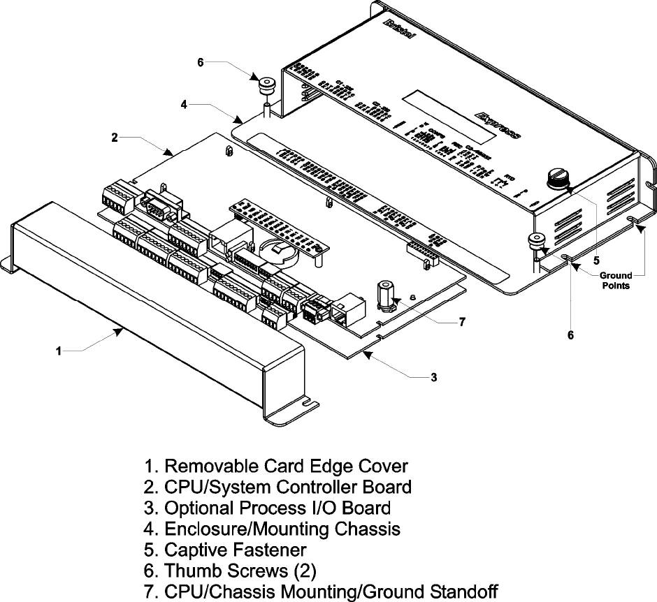
Figure 1-1 - ControlWave Express Component Identification
An optional Process I/O Board provides the circuitry and field interface hardware necessary
to interconnect all assigned field I/O circuits except the pulse counter circuits and the RTD
input that are located on the CPU/System Controller Board. Non-isolated power is
generated and regulated by the CPU/System Controller Board that provides +3.3Vdc for all
logic and bulk power for I/O field circuits from a nominal bulk +6Vdc, +12Vdc or +24Vdc
power source (depending on the type of CPU). +1.8Vdc, used by the ARM microprocessor, is
derived from the regulated 3.3Vdc logic power.
Click here to return to Table of Contents
CI-ControlWave Express Introduction / 1-3
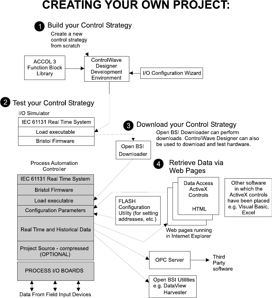
1.2 ControlWave PROGRAMMING ENVIRONMENT
The ControlWave programming environment uses industry-standard tools and protocols to
provide a flexible, adaptable approach for various process control applications in the water
treatment, wastewater treatment, and industrial automation business.
Figure 1-2 - ControlWave - Control Strategy Software Diagram
ControlWave Express RTUs provide an ideal platform for remote site automation,
measurement, and data management in the oil and gas industry.
The control strategy file created and downloaded into the controller is referred to as a
ControlWave project. The tools that make up the programming environment are:
Click here to return to Table of Contents
1-4 / Introduction CI-ControlWave Express
• ControlWave Designer programming package offers several different methods for
generating and debugging control strategy programs including function blocks, ladder
logic, structured languages, etc. The resulting programs are fully compatible with IEC
61131-3 standards. Various communication methods as offered, including TCP/IP, serial
links, as well as communication to Bristol Open BSI software and networks.
• The I/O Configuration Wizard, accessible via a menu item in ControlWave Designer,
allows you to define process I/O modules in the ControlWave and configure the
individual mapping of I/O points for digital and analog inputs and outputs.
• The ACCOL3 Firmware Library which is imported into ControlWave Designer,
includes a series of Bristol-specific function blocks. These pre-programmed function
blocks accomplish various tasks common to most user applications including alarming,
historical data storage, as well as process control algorithms such as PID control.
• The OPC Server (Object Linking and Embedding (OLE) for Process Control) allows
real-time data access to any OPC [Object Linking and Embedding (OLE) for Process
Control] compliant third-party software packages.
• Flash Configuration Utility – Parameters such as the BSAP local address, IP
address, etc. are set using the Flash Configuration Utility, accessible via Open BSI
LocalView, NetView, or TechView. The ControlWave Express ships with a standard
Flash Configuration Profile (FCP) file, with default configuration parameters already
set.
1.3 PHYSICAL DESCRIPTION
ControlWave Express RTUs are comprised of the following major components:
• Enclosure/Chassis (Section 1.3.1)
• RTD Probe (Section 1.3.2.1)
• CPU/System Controller Board (Section 1.3.2)
ControlWave Express RTUs can be factory configured with one or more of the following
options:
• Process I/O Board (Section 1.3.3)
• Keypad/LCD Display (1.5.2 & 2.4.5)
1.3.1 Enclosure/Chassis
ControlWave Express RTUs are housed in an enclosure that accommodates mounting to a
Panel or a DIN-Rail. External dimensions are approximately 10.75” long, by 5.56” wide, by
2.06” deep (without mounting brackets). The enclosure consists of two pieces, the removable
Card Edge Cover and the Main Mounting Chassis. Two Thumb Screws can be loosened to
facilitate removal of the Card Edge Cover, and thus accommodating all instrument field
wiring.
RJ-45 connector J2 on the CPU/System Controller Board accommodates either an optional
standalone dual line LCD display or optional 4 x 20 LCD display supported with either a 2-
button or a 25-button keypad. In normal operation, the LCD associated with a keypad will
turn off after the unit has been configured and placed into service while standalone LCDs
Click here to return to Table of Contents
CI-ControlWave Express Introduction / 1-5
will remain on. When interfaced to a keypad, the operator may activate the display at any
time by pressing the appropriate front panel button.
1.3.2 CPU/System Controller Board
The multilayer CPU/System Controller Board provides ControlWave Express CPU, I/O
monitor/control, memory and communication functions. ControlWave Express CPU/System
Controller Boards operate over an extended temperature range with long-term product
reliability.
ControlWave Express CPU/System Controller Boards are based on a 32-bit ARM9TDMI
RISC Core Processor. The CPU/System Controller Board is specified to operate with an
input voltage range from a nominal +6Vdc, +12Vdc or +24Vdc power supply with a system
clock speed of either 14 MHz or 33 MHz. In addition to the microprocessor and control logic,
the CPU Board includes two fixed RS-232 communication Ports (COM1 & COM2), and one
configurable RS-232/RS-485 communication port (COM3). CPU Memory consists of 2MB of
battery backed Static RAM (SRAM), 512kB Boot/Downloader FLASH and 8MB
simultaneous read/write FLASH. Three unique CPU/System Controller Boards are offered
as follows:
• 14 MHz Ultra Low Power CPU: operates from a nominal +6Vdc or +12Vdc bulk input
power and is equipped with a Solar Regulator circuit and an Auxiliary Power Output
circuit.
• 33 MHz Low Power CPU: operates from a nominal +12Vdc or +24Vdc bulk input power,
is equipped with a Solar Regulator circuit and an Auxiliary Power Output circuit).
• 33 MHz Low Power CPU: operates from a nominal +12Vdc or +24Vdc bulk input power
and is equipped with a 10/100Base-T Ethernet Port. Note: Not equipped with a Solar
Regulator circuit or an Auxiliary Power Output circuit.
CPU/System Controller Boards are provided backup power via a coin cell socket that
accepts a 3.0V, 300mA-hr lithium battery. This 3.0V battery provides backup power for the
real-time clock and the system’s Static RAM (SRAM). Backup power is enabled when
Configuration Jumper W3 (adjacent to the battery) is installed in position 1 to 2.
If the 3.3Vdc that powers the unit goes out of specification, a supervisory circuit on the
CPU/System Controller Board switches the battery voltage to the VBAT3.3 hardware signal
(used by the CPU’s SRAM and RTC). This supervisory circuit also generates a
BATTERYGOOD signal when the battery voltage is above 2.35V.
The system SRAM is specified to have a standby current of 20:A maximum for each part
(plus 2uA for the RTC). For a system containing 2MB of system SRAM, a worst-case
current draw of 42:A allows a battery life of approximately 9000 hours.
The power supply operates from a nominal +6Vdc, +12Vdc or +24Vdc (depending on the
CPU type) with the nominal input supply configuration being user configured via on-board
jumpers. A supervisory circuit monitors the incoming power and the supply voltages. The
isolated supplies are shut down when the incoming voltage drops below +5.4V for a +6.0V
system, +11.4V for a +12V system or +21.8V for a +24V system.
Click here to return to Table of Contents
1-6 / Introduction CI-ControlWave Express
S1
1234
123456 78
1
1
2
2
3
4
5
6
RJ-45
RJ-45
W3: 1-2 = Battery Enabled
2-3 = Battery Disabled
W2: 1-2 = COM2 CTS from Port
W5: 1-2 = 12/24V Power Supply
Shut-down Hysterisis
Shut-down Hysterisis
2-3 = 6V Power Supply
W6: 1-2 = 12V Power Supply
Shut-down
Shut-down
2-3 = 6/24V Power Supply
2-3 = COM2 CTS to RTS
W1: 1-2 = COM1 CTS from Port
2-3 = COM1 CTS to RTS
SW3 - COM3 Config.
RS-485 Receiver Biasing & Termination
2-Wire, 4-Wire Selction J5 - COM3
Piggy-back
Radio Intf.
J3 - I/OBUS
Intf. to
CPU Board
P1 WE
J7
MSP430
JTAG
Header
J9
PLD JTAG
Header
J8
Emulation
Header
J3
J5
W14
W16
W7
W1
3 2 1
W18
F3
W2
W3
W8
W6
W5
W15 W12
W13
Pulse
Input
LCD/
Keypad
Power
Power
GND
Sec. Battery Input
Power In +
Aux. Power Out +
Solar Pwr. In +
GND
GND
GND
P1 is only available on
Ultra Low Power CPU/-
System Controller Bds.
NOTE:
1
5
6
1
2
3
4
5
6
7
8
9
1
2
3
4
5
6
7
8
1
2
3
4
5
TXD-/TXD
GND
RXD+
RXD-/RXD
Input
Input
Output
Output TXD+
4
1
2
3
GND
PULSE 1
PULSE 2
Input
Input
Output PULSE
PWR
COM2
RS-232
10/100
Base-T
Ethernet
Port
COM1
RS-232
COM1
RS-232
Configuration
Options
Switch
Recovery
Mode &
COM./Status
LEDs
1
O
N
234
O
N
12345678
Receive
LED
Transmit
LED
TXD
GND
DCD
RXD
DTR
DSR
RTS
CTS
TXD
TXD
GND
GND
DCD
RXD
RXD
Input
Input
Output
Output
Output
Input
Input
Input
Input
Output
Output
Output
Input
Input
DTR
DSR
RTS
CTS
RTD
Input
1
2
3
RTD-
CAUTION:
Damage WILL occur to
the CPU if the Ethernet
network is connected
to connector J2!
RTD EXC
RTD+
COM3
RS-232
RS-485
PG
WD
STA6
STA5
STA4
STA3
STA2
STA1
TX1
RX1
TX3
RX3
TX2
RX2
IDLE
W12 - W16: 1-2 = COM3 RS-232
2-3 = COM3 RS-485
W7: 1-2 = 12/24V Power Fail
Trip Point Hysterisis
Trip Point Hysterisis
2-3 = 6V Power Fail
W8: 1-2 = 12V Power Fail
Trip Point
Trip Point
2-3 = 6/24V Power Fail
Trip Point
NOTE:
J7, J8, J9
Factory Use
W17
RJ-45
Solar Pwr. In and Aux. Power Out
are not available on units equipped
with an Ethernet Port.
Ultra Low Power & Low Power
CPU/System Controller Bds.
Don’t have an Ethernet Port.
NOTE:
Do Not Connect a 24V Solar Panel
to Connector TB1-1 & TB1-2!
Note: W17 is N/A on 24V Systems
Do Not Connect a 24V Solar
Panel to TB1-1 & TB1-2!
W17: 6/12V CPUs
1-2 = 6V S. P. Charging System
2-3 = 12V S. P. Charging System
W17: 12/24V CPUs
W18: COM1 connector
selection
1 to 2 = J4 active
2 to 3 = J11 active
1-2 = 12V S. P. Charging System
2-3 = N/A
NOTE:
J11 normally used
for CW GFC and CW
Express PAC only.
2 = Watchdog
1 = Idle
}
CR1
CR1 2
1
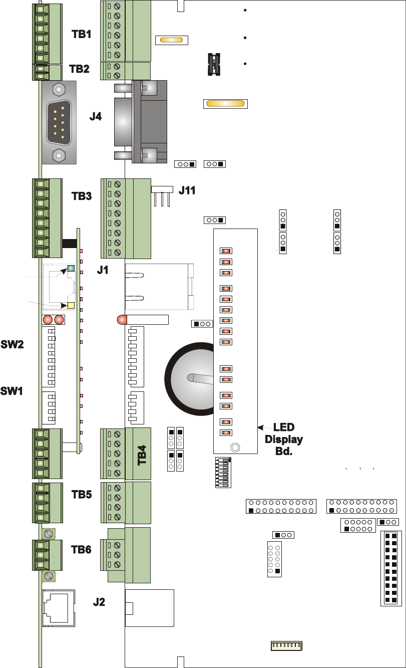
Figure 1-3 - ControlWave Express CPU/System Controller Board
Click here to return to Table of Contents

CI-ControlWave Express Introduction / 1-7
A supervisory circuit is used to switch to battery power when VCC falls out of specification.
For maximum shelf life, the battery may be isolated from the circuit by removing the
Backup Battery Jumper W3 from position 1 to 2 and then storing it in position 2 to 3. If the
real-time clock looses its battery backup a ControlWave Designer system variable bit
(_QUEST_DATE) is set. This bit can be used to post a message or alarm to the PC (see the
‘Systems Variables’ section of the ControlWave Designer Programmer’s Handbook D5125).
On 14MHz Ultra Low Power CPUs and 33 MHz Low Power CPUs, an on-board solar shunt
regulator is capable of charging a 7AH battery (6V or 12V) with the charging cycle
controlled by the MSP430 Microcontroller. Firmware turns on the shunt regulator when the
battery voltage exceeds the charge regulation threshold. When this happens, the shunt
regulator shorts the terminals of the solar panel connector thus eliminating further battery
charging. Note: Damage may result to the power supply components if the battery
charger is used without a battery present, i.e., do not connect a solar panel unless
a battery has first been connected.
An alternate battery connection is available through connector TB2 that provides power if
there is no power available from TB1.
Circuitry supports two Pulse Counter Inputs via connector TB5, and on 14 MHz Ultra Low
Power CPUs interface to a RTD via connector TB6.
Basic CPU components and features are summarized as follows:
• LH7A400 System-on-Chip 32-bit ARM9TDMI RISC Core microprocessor
• 512KB FLASH Boot/Downloader, 29LV040B, 90 nS, 8-bit access
• 2MB SRAM, 3.3V, 1M x 16, with Battery Backup
• 8MB simultaneous read/write FLASH, TSOP site
• 3 Serial Comm. ports
• Spread Spectrum clock for lower EMI
• Serial Real Time Clock with battery backup
• 8-Position configuration options switch bank (SW2), a 4-Position recovery switch bank
(SW1) and an 8-Position COM3 (RS-485) support switch bank (SW3)
• Coin cell socket accepts a 3.0V, 300mA-hr lithium battery
• LED Board (piggy-back)
• Nominal +6/12V or +12/24V) Power Input (both with Fail Safe Sequencer)
• Display/Keypad Interface
• 2 Pulse Counter Inputs with 1 second scan rate (Digital Input operation selectable)
• 10/100base-T Ethernet Port (Not on Low Power and Ultra Low Power CPUs)
1.3.2.1 CPU/System Controller Board Connectors
The CPU/System Controller Boards are equipped with up to ten (10) connectors that
function as stated in Table 1-1 below. Note: Additional connectors, not listed herein,
are for factory use only.
Table 1-1 - CPU/System Controller Board Connector Summary
Ref. # Pins Function Notes
J1 8-pin 10/100Base-T Ethernet Port RJ-45
J2 8-pin LCD Display/Keypad Intf. RJ-45
J3 20-pin IOBUS Intf. to Process I/O Board
J4 9-pin 9-pin Male D-type (COM1 - RS-232) Activated by W18
J10 20-pin LED Daughter Board Interface
J11 3-pin Alternate (COM1- RS-232) See Table 2-3B; Activated by W18
Click here to return to Table of Contents

1-8 / Introduction CI-ControlWave Express
Table 1-1 - CPU/System Controller Board Connector Summary (Continued)
Ref. # Pins Function Notes
TB1 6-pin Solar Panel, Battery/Power Supply &
Aux Out,
Main Power Connector
See Section 2.3.9
TB2 2-pin Secondary battery input
TB3 8-pin Term. Block (COM2 - RS-232) See Table 2-3A or 4-2
TB4 5-pin Term. Block (COM3 – RS-232/RS-485) See Table 2-3C or 4-3
TB5 4-pin Pulse Input Connector
TB6 3-pin RTD Input See Section 2.3.5
CPU/System Controller Board Optional Ethernet Port Connector J1
An optional Ethernet port is supported via 8-pin RJ-45 connector J1. The 10/100Base-T
Ethernet interface is implemented using an SMSC LAN91C111 controller. This device
provides for full or half-duplex implementation. It should be noted that units equipped with
an Ethernet Port do not support a Solar Panel or provide an Auxiliary Power Output.
CPU/System Controller Board Serial Comm. Port Connectors (see Section 1.5.5)
The CPU Module supports up to three serial communication ports (COM1, COM2 &
COM3). COM1 utilizes either a male 9-pin D-Type connector, or a male 3-pin connector –
choice of the active connector is determined by jumper W18. COM2 utilizes an 8-pin
Terminal Block and COM3 utilizes a 5-pin Terminal Block. COM1 and COM 2 support RS-
232 communications, COM3 can be configured to support RS-232 or RS-485
communications.
CPU/System Controller Board RTD Input Connector (also see Section 2.3.5)
Edge Connector TB6 (on 14MHz Ultra Low Power CPU/System Controller Boards) provides
connection to a 100-ohm platinum bulb (using the DIN 43760 curve). The common three-
wire configuration is accommodated. In this configuration, the return lead connects to the
RTD- terminal while the two junction leads (Sense and Excitation) connect to the RTD+
terminals.
CPU/System Controller Board Pulse Counter Input Connector (also see Section
2.3.4.9)
Edge Connector TB5 supports connection to two internally sourced Pulse Counter Inputs.
These inputs are sourced for 3.3V with a source current of 200μA and a maximum input
frequency of 10kHz. Pulse Counter inputs are not supported with debounce circuitry and
therefore should not be used with relays. Note: Pulse Counter Inputs can also be
configured for DI operation via ControlWave Designer.
CPU/System Controller Board Power Connections
A 6-position Terminal Block is provided for input power wiring as follows:
• TB1-1 - Solar Power In+: Power from a 1W - 6V, 5W - 6V or 5W - 12V Solar Panel
(Internally wired to recharge a user supplied battery) *
• TB1-2 - Ground (GND)
• TB1-3 - Primary Power: Power from a user supplied nominal +6Vdc, +12Vdc or
+24Vdc power supply (depending on the type of CPU)
Click here to return to Table of Contents
CI-ControlWave Express Introduction / 1-9
• TB1-4 - Ground (GND)
• TB1-5 - Auxiliary Power Out+: for an external radio/modem *
• TB1-6 - Ground (GND)
• TB2-1 - Secondary battery input
• TB2-2 - Ground (GND)
Note: * = Not available on units equipped with an Ethernet Port.
Power may be provided by a user supplied rechargeable 6/12V Lead Acid Battery (used in
conjunction with a Solar Panel), or a range of other user-supplied battery systems or bulk
(nominal +6Vdc, +12Vdc or +24Vdc) power supply.
Solar panels can be interfaced to rechargeable battery systems used to power a
ControlWave Express. Internally the solar panel wires connect to the rechargeable battery
via CPU/System Controller Board connector TB1-3 and TB1-4. A secondary power input
connection (TB2) is supported if no power is available through TB1.
Connector J2 (RJ-45) accommodates connection to one of three LCD Display configurations,
i.e., LCD Display only, LCD Display (with Dual-Button Keypad) or LCD Display (with 25-
Button Keypad). The LCD Display or LCD Display/Keypad is mounted on the Instrument
Front Cover.
1.3.2.2 CPU Memory
Boot/downloader FLASH
Boot/download code is contained in a single 512Kbytes uniform sector FLASH IC. This
device resides on the local bus, operates at 3.3V and is configured for 8-bit access. 4-
Position DIP-Switch SW1’s position 3 allows start-up menu options to be displayed or boot-
up from system FLASH. If SW1-3 is closed when a reset occurs, the boot-up code will cause
a recovery menu to be sent out the COM1 serial port to a terminal program running on an
external host computer. Note: Recovery Mode will also be initiated if CPU/System
Controller Board Switch SW1 positions 1 and 2 are both set ON or OFF when a reset occurs.
FLASH Memory
The base version of the CPU Module has 8Mbytes of 3.3V, simultaneous read/write (DL)
FLASH memory. FLASH memory is 16-bits wide. System Firmware and the Boot Project
are stored here. No hardware write protection is provided for the FLASH array.
System Memory (SRAM)
The base version of the CPU Module has 2Mbytes of soldered-down static RAM,
implemented with two 512K x 16 asynchronous SRAMs that are configured as a 1M x 16-bit
array. All random access memory retained data is stored in SRAM. During power loss
periods, SRAM is placed into data retention mode (powered by a backup 3.0V lithium
battery). SRAMs operate at 3.3V. Critical system information that must be retained during
power outages or when the system has been disabled for maintenance is stored here. Data
includes: Last states of all I/O, historical data, retain variables and pending alarm
messages not yet reported. The SRAM supports 16-bit accesses.
Click here to return to Table of Contents
1-10 / Introduction CI-ControlWave Express
1.3.2.3 CPU/System Controller Board Configuration Jumpers
ControlWave Express CPU/System Controller Board are provided with 12 User
Configuration Jumpers that function as follows:
• W1 - COM1 CTS Use Selection
1 to 2 = COM1 CTS Source is from Device
2 to 3 = COM1 RTS to CTS Loopback
• W2 - COM2 CTS Use Selection
1 to 2 = COM2 CTS Source is from Device
2 to 3 = COM2 RTS to CTS Loopback
• W3 - Enable/Disable Battery Backup Selection
1 to 2 = Enable Battery Backup
2 to 3 = Disable Battery Backup
• W5 - Power Supply Shut-down Selection
1 to 2 = 12/24V Power Supply Shut-down Hysterisis
2 to 3 = 6V Power Supply Shut-down Hysterisis
• W6 - Power Supply Shut-down Selection
1 to 2 = 12V Power Supply Shut-down
2 to 3 = 6/24V Power Supply Shut-down
• W7 - Power Fail Trip Point Hysterisis Selection
1 to 2 = 12/24V Power Fail Trip Point Hysterisis
2 to 3 = 6V Power Fail Trip Point Hysterisis
• W8 - Power Fail Trip Point Selection
1 to 2 = 12V Power Fail Trip Point
2 to 3 = 6/24V Power Fail Trip Point
• W12 - COM3 Configuration Selection
1 to 2 = COM3 is RS-232
2 to 3 = COM3 is RS-485
• W13 - COM3 Configuration Selection
1 to 2 = COM3 is RS-232
2 to 3 = COM3 is RS-485
• W14 - COM3 Configuration Selection
1 to 2 = COM3 is RS-232
2 to 3 = COM3 is RS-485
• W15 - COM3 Configuration Selection
1 to 2 = COM3 is RS-232
2 to 3 = COM3 is RS-485
• W16 - COM3 Configuration Selection
1 to 2 = COM3 is RS-232
2 to 3 = COM3 is RS-485
Click here to return to Table of Contents

CI-ControlWave Express Introduction / 1-11
• W17 - Input Power Selection (Controls Solar Power Shunt Reg.) N/A for +24Vdc CPUs
1 to 2 = 6V Power
2 to 3 = 12V Power
• W18 - COM1 Connector Selection
1 to 2 = Connector J4 (D connector) is active
2 to 3 = Alternate connector J11 is active
1.3.2.4 CPU/System Controller Board Configuration Switches
Three user-configurable DIP-Switches are provided on the CPU/System Controller Board.
These switches provide the following functionality:
• Four-bit DIP-Switch SW1 provides forced recovery functions. Recovery Mode as
supported by SW1-1 and SW1-2 or SW1-3 (forced by CW Console) accommodates FLASH
firmware upgrades to the CPU or allows the user to perform a Core Updump, i.e., upload
the contents of SRAM to a PC for evaluation (see Table 1-2).
• Eight-bit DIP-Switch SW2 is provided for user configuration settings (see Table 1-3).
• Eight-bit DIP-Switch SW3 provides loopback, termination control, and receiver bias
settings for the RS-485 port (COM3) (see Table 1-4).
Table 1-2 - CPU/System Controller Bd. SW1 Assignments
Recovery Mode/Local Mode Control
Switch Function Setting
SW1-1/2 Recovery/Local Mode
Both ON or OFF = Recovery Mode
SW1 OFF & SW2 ON = Local Mode
SW1-3 Force Recovery Mode ON = Force Recovery Mode (via CW Console)
OFF = Recovery Mode disabled
SW1-4 LED Status ON = Enable All LEDs
OFF = Disable All LED except Watchdog (WD)
* = Note: Only the Switch SW1 settings listed in this table, have been tested.
Table 1-3 - CPU/System Controller Bd. Configuration Switch SW2 Assignments
Note: Except for SW2-4, ON = Factory Default
Switch Function Setting - (ON = Factory Default)
SW2-1 Watchdog Enable
ON = Watchdog circuit is enabled
OFF = Watchdog circuit is disabled
SW2-2 Lock/Unlock
Soft Switches
ON = Write to Soft Switches and FLASH files
OFF = Soft Switches, configurations and FLASH files are locked
SW2-3 Use/Ignore
Soft Switches
ON = Use Soft Switches (configured in FLASH)
OFF = Ignore Soft Switch Configuration and use factory defaults
SW2-4 Core Updump
See Section 3.6
ON = Core Updump Disabled
OFF = Core Updump Enabled via Mode Switch (SW1)
SW2-5 SRAM Control ON = Retain values in SRAM during restarts
OFF = Force system to reinitialize SRAM
SW2-6 System Firmware
Load Control *
ON = Enable remote download of System Firmware
OFF = Disable remote download of System Firmware
SW2-7 N/A
SW2-8 Enable
WINDIAG
ON = Normal Operation (don’t allow WINDIAG to run test)
OFF = Disable boot project (allow WINDIAG to run test)
* = Boot PROM version 4.7 or higher and System PROM version 4.7 or higher
Click here to return to Table of Contents

1-12 / Introduction CI-ControlWave Express
Table 1-4 - CPU/System Controller Bd. Switch SW3 Assignments
RS-485 Loopback & Termination Control (COM3)
Switch RS-485 Function
Switch ON Setting
SW3-1 TX+ to RX+ Loopback/2-Wire ON – 2-Wire Operation or Loopback Enabled
OFF – 4-Wire Operation & Loopback Disabled
SW3-2 TX− to RX− Loopback/2-Wire ON – 2-Wire Operation or Loopback Enabled
OFF – 4-Wire Operation & Loopback Disabled
SW3-3 100 Ohm RX+ Termination ON – End Nodes Only
SW3-4 100 Ohm RX− Termination ON – End Nodes Only
SW3-7 RX+ Bias (End Nodes/Node)
ON – 4-Wire = Both End Nodes
2-Wire = One End Node Only
OFF – No Bias
SW3-8 RX− Bias (End Nodes/Node)
ON – 4-Wire = Both End Nodes
2-Wire = One End Node Only
OFF – No Bias
1.3.2.5 CPU/System Controller Board LEDs – LED Board
CPU/System Controller Boards are equipped with a piggyback mounted LED Board. These
LEDs provide the following status conditions when lit:
PG (Red) - Power Good
WD (Red) - a Watchdog condition has been detected
IDLE (Red) - the CPU has free time at the end of its execution cycle
TX1, TX2, TX3 (Red) - transmit activity on COM1, COM2 & COM3 (respectively)
RX1, RX2, RX3 (Red) - receive activity on COM1, COM2 & COM3 (respectively)
Six Status LEDs (Red) - provide run time status codes.
Normally, the Idle LED should be ON most of the time (unless disabled). When the Idle
LED is OFF, it indicates that the CPU has no free time, and may be overloaded.
1.3.2.6 CPU/System Controller Board LEDs
CPU/System Controller Boards are equipped with two red LEDs that provide the following
status conditions when lit: WD (CR1 - Right) – Indicates Watchdog condition has been
detected & IDLE (CR1 - Left) - Indicates the CPU has free time at the end of its execution
cycle. Normally, the Idle LED should be ON most of the time (unless disabled). When the
Idle LED is OFF, it indicates that the CPU has no free time, and may be overloaded.
1.3.3 Process I/O Board
The Process I/O Board is mounted to the CPU/System Controller Board via six nylon
mounting posts.
Interface to the CPU/System Controller Board is provided via a 20-pin connector (P1).
Process I/O Boards contain I/O circuitry that supports the following I/O:
• Four Dedicated Non-Isolated Internally Sourced Digital Inputs
• Two Dedicated Non-Isolated Digital Outputs
• Two Selectable Non-Isolated Digital I/Os which can be individually wired for
Internally-Sourced DI operation or DO operation
Click here to return to Table of Contents
CI-ControlWave Express Introduction / 1-13
• Two Non-Isolated Internally-Sourced High Speed Counter Inputs (or DI operation
supported)
• Three Non-Isolated Single-Ended 1-5V or 4 to 20mA Analog Inputs (Optional)
• One Non-Isolated Externally-Powered 1-5V or 4 to 20mA Analog Output (Optional)
1.3.3.1 Process I/O Board Configuration Jumpers and Switch SW1
ControlWave Express I/O Boards are provided with 6 User Configuration Jumpers and one
4-position DIP-Switch (SW1) that function as follows:
• JP1 - AO Output Source (1-5V or 4-20mA)
1 to 2 = 4-20mA Analog Output
2 to 3 = 1-5V Analog Output
• JP3 - AO Power Source
1 to 2 = System Power
2 to 3 = External Power (+11 to +30 Vdc)
• JP4 - AI Field Power Configuration
1 to 2 = External Power
2 to 3 = System Power
• JP5 - AI1 Input Type (1-5V or 4-20mA)
1 to 2 = 4-20mA Analog Input
2 to 3 = 1-5V Analog Input
• JP6 - AI2 Input Type (1-5V or 4-20mA)
1 to 2 = 4-20mA Analog Input
2 to 3 = 1-5V Analog Input
• JP7 - AI3 Input Type (1-5V or 4-20mA)
1 to 2 = 4-20mA Analog Input
2 to 3 = 1-5V Analog Input
• SW1 - HSC high/low frequency select, DI/HSC Source Current & AO Configuration
SW1-1: HSC1 – OFF= 10 kHz (high speed), ON = 300 Hz (low speed)
SW1-2: HSC2 – OFF= 10 kHz (high speed), ON = 300 Hz (low speed)
SW1-3: DI/HSC 2mA Source Current – OFF = Disabled, ON = Enabled
SW1-4: AO Configuration – OFF = Current, ON = Voltage
Click here to return to Table of Contents

1-14 / Introduction CI-ControlWave Express
Figure 1-4 - ControlWave Express Process I/O Board
Click here to return to Table of Contents

CI-ControlWave Express Introduction / 1-15
1.3.3.2 Process I/O Board Connectors
Process I/O Boards are equipped with up to six (6) I/O interface connectors that function as
follows (see Table 1-5):
Table 1-5 - Process I/O Board Connector Summary
Ref. # Pins Function Notes
P1 20-Pin Bd. Power and I/O Bus Intf. to CPU/System Controller Bd.
TB2 6-Pin Digital Input (DI1 – DI4) Interface see Section1.3.3.3.1
TB3 8-pin Digital Output (DO1 & DO2) & DI/O
(DI5/DO3 & DI6/DO4) Interface
see Section 1.3.3.3.2 for DO
see Section 1.3.3.3.3 for DI/O
TB4 8-pin High Speed Counter Input Interface see Section 1.3.3.3.6
TB6 9-pin Analog Input Interface see Section 1.3.3.3.4
TB7 4-pin Analog Output Interface see Section 1.3.3.3.5
1.3.3.3 Process I/O Board Field I/Os
Field I/O Wiring is supported by card edge Terminal Block Connectors as follows:
Non-isolated Digital Input (DI) Connector (Section 1.3.3.3.1)
Non-isolated Digital Output (DO) & Digital I/O Connector (Sections 1.3.3.3.2 & 1.3.3.3.3)
Non-isolated Analog Input Connector (Section 1.3.3.3.4)
Non-isolated Analog Output Connector (Section 1.3.3.3.5)
Non-isolated High Speed Counter Input Connector (Section 1.3.3.3.6)
1.3.3.3.1 Dedicated Non-isolated Digital Inputs (also see Section 2.3.4.3)
Terminal Block TB2 provides interface to 4 dedicated non isolated Digital Inputs DIs). All
Digital Inputs support dry contact inputs that are pulled internally to 3.3 Vdc when the
field input is open. Source current for DI#1 through DI#4 is switch selectable for 60uA or
2mA from the 3.3V supply (SW1-3 ON = 2mA, OFF = 60uA). Note: SW1-3 also sets DI5 &
DI6 and both HSCs (for 200uA or 2.2mA operation). 15 millisecond input filtering protects
against contact bounce.
1.3.3.3.2 Dedicated Non-isolated Digital Outputs (also see Section 2.3.4.4)
Terminal Block TB3 provides interface to 2 dedicated non isolated Digital Outputs (DOs)
and two selectable DI/Os. Digital Outputs have a 30V operating range and are driven by
Open Drain FETs that sink 400 mA (Max.) at 30Vdc. The maximum output frequency is 20
Hz. Transorbs (30Vdc) provide surge suppression between each signal and ground.
Selectable DI/Os are discussed in section 1.3.3.3.3.
1.3.3.3.3 Selectable Non-isolated Digital Inputs/Outputs (also see Section 2.3.4.5)
Terminal Block TB3 also supports 2 user selectable Digital Inputs/Outputs. These DI/Os
may be unused or individually user wired as desired, i.e., both DI, both DO, one DI and/or
one DO. Their operation depends on how they are wired, i.e., DI or DO. These DI/Os are
rated identically to the DIs and DOs discussed in Sections 1.3.3.3.1 and 1.3.3.3.2.
1.3.3.3.4 Non-isolated Analog Inputs (also see Section 2.3.4.6)
Terminal Block TB6 provides interface to three single-ended Analog Inputs. Three field
terminals are assigned for each Analog Input, i.e., Field Power, AI# and DGND. AI field
Click here to return to Table of Contents
1-16 / Introduction CI-ControlWave Express
power is applied to the field device (controlled via jumper JP4) and can be supplied by the
system battery or an external power source. Each AI channel can be individually configured
for 4 to 20mA or 1-5V operation (via JP5 for AI1, JP6 for AI2 and JP7 for AI3).
AIs are supplied with a two hertz low pass filter and surge suppression (via 30Vdc
Transorbs).
1.3.3.3.5 Non-isolated Analog Output (also see Section 2.3.4.7)
Terminal Block TB7 provides interface to 1 Analog Output. The AO channel can be
configured for an internal or external power source via jumper JP3. External power can
range from +11 to + 30 Vdc.
Analog Output circuitry consists of a 12-bit resolution Digital to Analog Converter, a V to I
circuit and a V to V circuit. 4 to 20mA or 1-5V operation is jumper configured via JP1. An
ultra low power 16-bit RISC Microcontroller (MSP) reads the state of SW1-4 and selects the
appropriate calibration data for the AO channel.
1.3.3.3.6 Non-isolated High Speed Counter Inputs (also see Sections 2.3.4.8)
Terminal Block TB4 provides the interface to two internally-sourced single-ended High
Speed Counter or Digital Inputs (HSCI) with selectable high (10 kHz)/ or low (300 Hz)
frequencies (SW1-1 for HSC1 & SW1-2 for HSC2). All Input circuits have surge suppression
and signal conditioning. HSCs can be interfaced via Dry Contacts or Open Collector field
circuits. Note: High Speed Counter Inputs can also be configured for DI operation
via ControlWave Designer.
High Speed Counter/Digital inputs are sourced from 3.3Vdc and are switch selectable for a
source current of 200uA or 2.2mA (SW1-3 ON = 2.2mA, OFF = 200uA). Note: SW1-3 sets all
DIs and all HSCs. Each HSC circuit has a maximum input frequency of 10 kHz.
1.4 FIELD WIRING
ControlWave Express remote terminal units support connection to external field devices
through field wiring terminals on the CPU/System Controller Board and the Process I/O
Board. Connections to the following types of external devices may be made:
• RTD (CPU Bd.) • Pulse Inputs* (CPU Bd.)
• Analog Inputs (AIs) (I/O Bd.) • Analog Outputs (AOs) (I/O Bd.)
• Digital Inputs (DIs) (I/O Bd.) • Battery/Power Supply/Solar Panel (CPU Bd.)
• Digital Outputs (DOs) (I/O Bd.) • Communications (RS-232 and RS-485) (CPU Bd.)
• Relays (HSCs*) (I/O Bd.)
* Pulse Inputs and HSC Inputs can also be configured for use as Digital Inputs.
1.5 FUNCTIONS
ControlWave Express RTUs are shipped without a base application program. Using
ControlWave Designer, the user can readily modify this application and then add or
subtract functions, etc. An overview of a typical application is provided below.
Click here to return to Table of Contents

CI-ControlWave Express Introduction / 1-17
• Uses pre-configured web pages for user readings, configuration and maintenance. Web
pages can be modified and new pages configured to work with a modified application
load
• Resides on a BSAP SCADA network
• Provides audit trail and archives
• Allows the user to select engineering units, including English and metric
The primary function of the ControlWave Express is to provide data acquisition, a local
display, communications, output control, input status and self test and diagnostics. Items
below implement and supplement the primary function:
• Data acquisition (see Section 1.5.1)
• Local display (see Section 1.5.2)
• Communications (see Section 1.5.3)
• Control outputs (see Section 1.5.4)
• Status inputs (see Section 1.5.4)
• Self test and diagnostics (see Section 1.5.5)
1.5.1 Data Acquisition
Typical process inputs used by the ControlWave Express are pressure, flow, level,
temperature and frequency input [typically used for positive displacement (PD)], turbine, or
ultrasonic meters. In some cases, inputs may also be derived from external Multivariable
Transmitters using either the BSAP or MODBUS protocols. Alternatively, the inputs may
be obtained via the local I/O Modules using analog transmitters. The ControlWave Express
application program will typically allow any combination of inputs to be selected.
1.5.2 Optional LCD Display
In normal operation, the Display only LCD Display remains ON while the Dual-Button or
25-Button Keypad/Displays turn OFF after the unit has been configured and placed in
service. The operator may activate the Keypad/Display at any time by pressing the
appropriate front panel button (depending on the keyboard type). When activated, the
display scrolls through a list of current values. The list defaults to an appropriate set of
values.
1.5.3 Communications
A ControlWave Express can be configured as a Master or Slave node on either a MODBUS
network or a BSAP network. Up to three serial communication ports are contained on the
ControlWave Express CPU/System Controller Board. Communication ports situated on the
CPU/System Controller Board are designated as follows:
CPU/System Controller Board:
COM1 - Port 1: J4 - 9-Pin Male D-Type Connector - RS-232 (Activated by jumper W18)
J11- 3-Pin Connector – RS-232 (Activated by jumper W18)
COM2 - Port 2: TB3 - 8-Pin Term Block - RS-232 (COM2 supports an External Modem or
Radio option)
COM3 - Port 3: TB4 - 5-Pin Term Block - RS-232/RS-485 (Configuration: RS232/485 via
jumpers W12 through W16 and RS-485 via switch SW3)
Communication Ports COM1, COM2 & COM3 support serial asynchronous operation.
Communication Ports COM1 and COM2 support RS-232 operation while COM3 supports
Click here to return to Table of Contents
1-18 / Introduction CI-ControlWave Express
RS-232 or RS-485 operation. Any serial communication port can be configured for local
communications, i.e., connected to a PC loaded with ControlWave Designer and OpenBSI
software.
RS-232 Ports
An RS-232 interface supports Point-to-Point, half-duplex and full-duplex communications
(20 feet maximum, using data quality cable). Half-duplex communications supported by the
ControlWave Express utilize MODBUS or BSAP protocol, while full-duplex is supported by
the Point-to-Point (PPP) protocol. ControlWave Express RS-232 ports utilize the “null
modem” cable (Figure 2-11A) to interconnect with other devices such as a PC, printer,
another ControlWave series unit (except CW_10/30/35) when the ControlWave Express is
communicating using the full-duplex PPP protocol.
RS-485 Ports
ControlWave Express RTUs can use an RS-485 communication port for network
communications to multiple nodes up to 4000 feet away. Essentially, the master and the
first slave transmit and receive data on opposite lines; all slaves (from the first to the "nth")
are paralleled (daisy-chained) across the same lines. The master node should be wired to
one end of the RS-485 cable run. A 24-gauge paired conductor cable, such as Belden 9843
should be used. Note: Only half-duplex RS-485 networks are supported.
Comm. Port Defaults
From the factory COM1 defaults to 115.2 kilo-baud using the BSAP protocol. The
remaining serial communication ports, i.e., COM2 and COM3 default as follows:
COM2 – BSAP Slave @ 9600 Baud
COM3 – BSAP Master @ 9600 Baud (for use with Bristol 3808 MVT Transmitters)
Click here to return to Table of Contents

CI-ControlWave Express Installation & Operation / 2-1
Section 2
ControlWave Express INSTALLATION & OPERATION
2.1 INSTALLATION IN HAZARDOUS AREAS
Each ControlWave Express RTU is furnished in an enclosure/chassis that accommodates
mounting to a Panel or a DIN-Rail and have been designed to operate in a protected Class
I, Division 2, Groups C & D environment with a nonincendive rating (see Appendix A).
Figure 2-1 - ControlWave Express Component Identification
A Dimensional drawing of the NEMA Enclosure is provided in Figure 2-2.
2.2 SITE LOCATION CONSIDERATIONS
Check all clearances when choosing an installation site. Make sure that the ControlWave
Express is accessable for wiring and service. If present, make sure that the optional
LCD/Keypad is visible and accessible to the on-site operator. External dimensions are
approximately 10.75” long, by 5.56” wide, by 2.06” deep (without mounting brackets). The
enclosure consists of two pieces, the removable Card Edge Cover and the Main Mounting
Click here to return to Table of Contents
2-2 / Installation & Operation CI-ControlWave Express
Chassis. Two Thumb Screws can be loosened to facilitate removal of the Card Edge Cover,
and thus accommodating all instrument field wiring. Information on mounting the
ControlWave Express assembly is provided in Section 2.3.1 Mounting the ControlWave
Express.
2.2.1 Temperature & Humidity Limits
ControlWave Express RTUs have been designed to operate over a -40°F to +158°F (-40°C
to +70°C) temperature range (with storage at up to +185°F (+85°C)) and a 0% to 95%
relative humidity range. Make sure that the ambient temperature and humidity at the
measuring site remains within these limits. Operation beyond these ranges could cause
output errors and erratic performance. Prolonged operation under extreme conditions could
also result in failure of the unit.
2.2.2 Vibration Limits
Check the mounted enclosure, panel or equipment rack for mechanical vibrations. Make
sure that the ControlWave Express is not exposed to a level of vibration that exceeds those
given in the specifications. ControlWave Express vibration limits are 1g for 10 - 150 Hz &
.5g for 150 - 2000 Hz.
2.3 ControlWave Express INSTALLATION/CONIGURATION
Overview of Configuration
An overview of the main configuration steps are provided herein.
Step 1. Hardware Configuration
This involves unpacking the ControlWave Express hardware, mounting the
enclosure/chassis, wiring I/O terminations, connecting any permanent communication
cables, making proper ground connections, connecting a communication cable to a PC
workstation, setting switches and setting jumpers. To install and configure the
ControlWave Express, follow the steps below:
1. Remove the unit from its carton and install it onto a panel or DIN-rail in an
appropriate enclosure and then ultimately at the assigned work site (see Section
2.3.1). Dimensions are provided in Section 4.6 of this manual.
2. Remove the Process I/O Board and the CPU/System Controller Board (as one
assembly).
3. Make sure that the Lithium Backup Battery has been enabled, i.e., Backup Battery
Jumper W3 on the CPU/System Controller Assembly should be installed on jumper
posts 1-2). Configure the CPU/System Controller Board DIP-Switches and Jumpers
(see Sections 2.3.3 & 2.3.3.1). Configure the Process I/O Board’s DIP-Switches and
Jumpers (see Section 2.3.2). After configuring the Jumpers and DIP-Switches,
install the Process I/O Board and the CPU/System Controller Board (as one
assembly) into the enclosure.
4. Configure/Connect appropriate communication port(s) (see Section 2.3.3.2). Connect
COMM. Port 1 or 2 of the ControlWave Express (depending on CPU/System
Controller Board Switch SW2 settings - see Section 2.3.3.1) to a Communication Port
of a PC (typically PC COMM. Port 1). Note: Also see Section 2.4.4.
Click here to return to Table of Contents

CI-ControlWave Express Installation & Operation / 2-3
5. Install I/O wiring to the Process I/O Board and to the CPU/System Controller Board
if Pulse Inputs are present (see Section 2.3.4). Install a communications cable to a
Model 3808 Transmitter if required (see Section 2.3.6).
6. Install a ground wire between the Enclosure and a known good Earth Ground (see
Section 2.3.7.3).
7. If required, install the RTD Probe (see Section 2.3.5)
8. Connect DC Power wiring to the ControlWave Express CPU/System Controller
Board (see Sections 2.3.7.1 & 2.3.7.2).
9. Apply power to the ControlWave Express. Now continue with Steps 2 through 7
below (and Section 2.4.1) and the ControlWave Express will be ready for on-line
operation.
Step 2. Software Installation on the PC Workstation
ControlWave Designer software must be installed on the PC. The completed project is
downloaded into the unit from Open BSI Downloader or from ControlWave Designer. This
will require the installation of the ControlWave Designer Package from the Open BSI
CD-ROM onto the PC.
You must install the Open BSI Network Edition. For information on minimum system
requirements and more details on the installation, see the installation procedure in
Chapter 2 of the Open BSI Utilities Manual (document # D5081).
If you have an older version of ControlWave Designer already installed:
Beginning with ControlWave Designer Version 3.3, the copy protection key (dongle) is NOT
required. Prior to installing ControlWave Designer 3.3 or newer, you MUST remove the
hardware dongle from the parallel port of your PC workstation. Otherwise, when you
subsequently start ControlWave Designer, it will operate only in ‘DEMO’ mode, and will
limit the available system resources.
IMPORTANT:
When you start ControlWave Designer, you will be reminded to register the
software. Unregistered software can only be used for a maximum of 30 days. For
more information on the registration process, see Chapter 2 of the Open BSI
Utilities Manual (document# D5081).
Step 3. Establish Communications using either LocalView, NetView, or TechView
and Run the Flash Configuration Utility
Communications must be established with the ControlWave Express using LocalView,
NetView, or TechView.
ControlWave Express RTUs ship from the factory with a default Flash configuration. Most
users will need to edit this configuration to set the IP address (if using PPP), BSAP local
address, user accounts, and port parameters. This can be done in one of two ways:
• Either open the supplied Flash Configuration Profile (FCP) file and modify it, directly in
the Flash Configuration Utility, or in a text editor,
• Or retrieve existing Flash Parameters directly from the unit, and edit them in the Flash
Configuration Utility.
Click here to return to Table of Contents
2-4 / Installation & Operation CI-ControlWave Express
Detailed information on the Flash Configuration Utility, and LocalView is included in
Chapter 5 of the Open BSI Utilities Manual (document # D5081). NetView is described in
Chapter 6 of that same manual. TechView is described in the TechView User’s Guide
(document# D5131).
Step 4. Create an Application-Specific Control Strategy in ControlWave Designer
At this point, you can create your application-specific control strategy using ControlWave
Designer. This involves opening a new project using the ‘CWMicro’ template, defining I/O
boards using the I/O Configurator, and creating a program using one or more of the five
supported IEC 61131 languages (FBD, ST, SFC, LD, or IL). Some of these languages are
text-based, others use graphical diagrams. The choice is up to you, depending upon your
particular application.
The ControlWave MICRO Quick Setup Guide (document # D5124) includes a simple LD
example. Additional examples are included in the manual, Getting Started with
ControlWave Designer (document # D5085). More detailed information about ControlWave
Designer and IEC 61131 is included in the ControlWave Designer Reference Manual
(document # D5088).
The ACCOL3 Firmware Library, which is automatically accessible through the template
referenced above, includes a series of function blocks which perform a variety of process
control and communication functions. These can be included within your program to
perform various duties including PID control, alarming, calculations, etc. Detailed
information about each function block is included in the ControlWave Designer on-line help
files.
On the variables declaration page(s) in ControlWave Designer, you will need to mark any
variable you want to make accessible to external programs, such as Open BSI’s DataView
utility, as “PDD”. Similarly, any variables which should be collected into a database, or
exported using the OLE for Process Control (OPC) Server must be marked as “OPC”.
Variables marked as OPC can be built into a text file by the OpenBSI Signal Extractor.
The text file can then be used in the creation of a database for human machine interface
(HMI) software such as OpenEnterprise or Iconics’ Genesis. These HMI software packages
require that the "Datatype conversion enable" option be selected when generating the
file using Signal Extractor. Information about the OpenBSI Signal Extractor is included in
Chapter 12 of the Open BSI Utilities Manual (document # D5081).
Once the program has been created, it is assigned to an executable task. The entire project
is then saved and compiled.
NOTE: From this point on, the order of steps may be varied, somewhat,
depending upon the requirements of the user's application.
Step 5. Create Application-Specific Web Pages (OPTIONAL)
ControlWave Express RTUs support a set of standard web pages for data collection
purposes and for access to communication statistics maintained in the controller.
Optionally, additional user-created web pages may be created to allow a customized
human-machine interface. A series of ActiveX controls for data collection and configuration
are provided on the OpenBSI CD which can be included as part of these user-created web
pages. For information on the ActiveX controls, see the Web_BSI Manual (document #
D5087).
Click here to return to Table of Contents
CI-ControlWave Express Installation & Operation / 2-5
You can use whichever HTML creation package you want to create the pages, however, all
ControlWave Express related web pages (whether standard or user-created) must be viewed
within Microsoft® Internet Explorer. The web pages may reside either on a PC workstation,
or they can be downloaded into FLASH memory at the ControlWave Express. If stored at
the ControlWave Express, you must use the ControlView utility to retrieve the pages (using
FTP) for viewing in Internet Explorer.
Step 6. Create an Open BSI Network Containing the ControlWave Express, or
ADD the ControlWave Express to an Existing Open BSI Network
In order for the ControlWave Express unit to function as part of a Bristol network, it is
necessary to include it in the Bristol network.
If no Bristol network exists:
You need to run Open BSI’s NetView software on the PC workstation in order to define
a Bristol network. A series of software wizards are used to define a Network Host PC, a
network, and the RTUs (controllers) assigned to the network. Finally, communication
lines must be specified which handle the address assigned to the ControlWave Express.
Chapters 3 and 4 of the Open BSI Utilities Manual (document # D5081) include ‘quick
start’ examples for performing these steps. More detailed information is included in the
NetView chapter (Chapter 6) of D5081.
If a Bristol network already exists:
You will need to add the ControlWave Express to the existing network using NetView’s
RTU Wizard. Chapter 6 of the Open BSI Utilities Manual (document # D5081) includes
different sub-sections depending upon whether you are adding the unit to a BSAP
network, or an IP network.
Step 7. If applicable, download new or modified control strategy (OPTIONAL)
If you modify a ControlWave Express program, or create your own program, compile and
download the new or modified program into the unit, using either ControlWave Designer, or
the Open BSI 1131 Downloader. In this case, you download the control strategy into the
BOOT project area of FLASH memory; this ensures that if the ControlWave Express is
reset, or if there has been a failure of the backup battery, the control strategy can be
restarted from the beginning, i.e. from the BOOT project in FLASH memory. To download
the project, see Section 2.4.1.
2.3.1 Mounting the ControlWave Express Enclosure/Chassis
When mounting one of these units, it is to be installed in accordance with the following
restrictions:
- The unit may be positioned vertically or horizontally. Units can be mounted to a panel
directly or via a DIN-Rail Mounting Bracket (utilizing a 35mm DIN-Rail). The basic
unit measures 10.75” long, by 5.56” wide, by 2.06” deep (without mounting brackets).
- The unit must be positioned such that the front of the assembly is visible and the unit
is accessible for service, i.e., replacement of the Lithium Battery, or installation and
removal of any ControlWave Express option.
Click here to return to Table of Contents

2-6 / Installation & Operation CI-ControlWave Express
Figure 2-2 - ControlWave Express Dimensions
- Power wiring should not be installed until the unit has been mounted and grounded at
a designated work site.
- I/O wiring, external power wiring, local comm. port, and network (RS-232 and RS-485)
comm. port cabling enter the unit though a slot on the left side of the Removable Card
Edge Cover.
Click here to return to Table of Contents
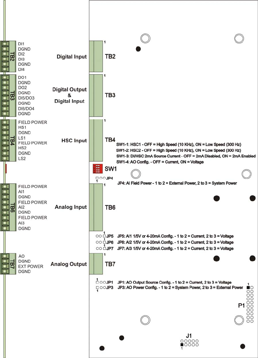
CI-ControlWave Express Installation & Operation / 2-7
2.3.2 Process I/O Board Configuration
I/O Board jumpers and Switch SW1 must be set to configure field I/O (see Figure 2-3).
Figure 2-3 - Process I/O Board Component Identification Diagram
Click here to return to Table of Contents

2-8 / Installation & Operation CI-ControlWave Express
2.3.3 CPU/System Controller Board Configuration
To configure the CPU/System Controller Board, Jumpers must be set (see Figure 2-4), DIP-
Switches must be set (see Section 2.3.3.1) and Communication Ports must be wired (see
Sections 2.3.3.2 through 2.3.3.3).
For safety reasons and to prevent accidental damage to a user-supplied external bulk DC
Power Supply, it is recommended that the pluggable Power Terminal Blocks TB1 and TB2 on
the CPU/System Controller Board be disconnected until the entire unit has been wired, and
hardware configured. Sections 2.3.7.1 & 2.3.7.2 provide details on DC Power Connector wiring.
2.3.3.1 CPU/System Controller Board Switch Configuration
ControlWave Express CPU/System Controller Board Switches must be set for the desired
performance options. Tables 2-1, 2-2 and 2-5 provide an overview of switch settings.
SW2-1 set OFF will disable the system from entering a watchdog state when a crash or
system hang up occurs. Setting SW2-1 OFF prevents the system from automatically
restarting.
SW2-2 set OFF prevents changing the Soft Switches, other configurations and FLASH files,
i.e., these items are locked. To change Soft Switch, configuration and FLASH files SW2-2
must be set to the ON position (see Section 2.4.4).
Table 2-1 - CPU/System Controller Bd. Configuration Switch SW2 - Assignments
Note: Except for SW2-4, ON = Factory Default
SW# Function Setting - (ON = Factory Default)
SW2-1 Watchdog Enable ON = Watchdog circuit is Enabled
OFF = Watchdog circuit is Disabled
SW2-2 Lock/Unlock
Soft Switches
ON = Write to Soft Switches and FLASH files
OFF = Soft Switches, configurations and FLASH files are locked
SW2-3 Use/Ignore
Soft Switches
ON = Use Soft Switches (configured in FLASH)
OFF = Ignore Soft Switch Configuration and use factory defaults
SW2-4 Core Updump
See Section 3.6
ON = Core Updump Disabled
OFF = Core Updump Enabled via Mode Switch (SW1)
SW2-5 SRAM Control ON = Retain values in SRAM during restarts
OFF = Force system to reinitialize SRAM
SW2-6 System Firmware
Load Control *
ON = Enable remote download of System Firmware
OFF = Disable remote download of System Firmware
SW2-7 N/A
SW2-8 Enable WINDIAG ON = Normal Operation (don’t allow WINDIAG to run test)
OFF = Disable boot project (allow WINDIAG to run test)
* = Boot PROM version 4.7 or higher and System PROM version 4.7 or higher
SW2-3 set OFF forces the use of Soft Switches as set per factory default (see Section 2.4.4).
For use of user defined Soft Switches, SW2-3 must be set to the ON position. Note: If both
SW2-3 and SW2-8 are set OFF (closed), all communication ports will be set to 9600 bps
operation.
SW2-4 set OFF and used in conjunction with Mode Switch (SW1) will cause the
ControlWave Express to perform a Core Updump (see Section 3.6).
Click here to return to Table of Contents

CI-ControlWave Express Installation & Operation / 2-9
S1
1234
12345678
1
1
2
2
3
4
5
6
RJ-45
RJ-45
W3: 1-2 = Battery Enabled
2-3 = Battery Disabled
W2: 1-2 = COM2 CTS from Port
W5: 1-2 = 12/24V Power Supply
Shut-down Hysterisis
Shut-down Hysterisis
2-3 = 6V Power Supply
W6: 1-2 = 12V Power Supply
Shut-down
Shut-down
2-3 = 6/24V Power Supply
2-3 = COM2 CTS to RTS
W1: 1-2 = COM1 CTS from Port
2-3 = COM1 CTS to RTS
SW3 - COM3 Config.
RS-485 Receiver Biasing & Termination
2-Wire, 4-Wire Selction J5 - COM3
Piggy-back
Radio Intf.
J3 - I/OBUS
Intf. to
CPU Board
P1 WE
J7
MSP430
JTAG
Header
J9
PLD JTAG
Header
J8
Emulation
Header
J3
J5
W14
W16
W7
W1
3 2 1
W18
F3
W2
W3
W8
W6
W5
W15 W12
W13
Pulse
Input
LCD/
Keypad
Power
Power
GND
Sec. Battery Input
Power In +
Aux. Power Out +
Solar Pwr. In +
GND
GND
GND
P1 is only available on
Ultra Low Power CPU/-
System Controller Bds.
NOTE:
1
5
6
1
2
3
4
5
6
7
8
9
1
2
3
4
5
6
7
8
1
2
3
4
5
TXD-/TXD
GND
RXD+
RXD-/RXD
Input
Input
Output
Output TXD+
4
1
2
3
GND
PULSE 1
PULSE 2
Input
Input
Output PULSE
PWR
COM2
RS-232
10/100
Base-T
Ethernet
Port
COM1
RS-232
COM1
RS-232
Configuration
Options
Switch
Recovery
Mode &
COM./Status
LEDs
1
O
N
234
O
N
12345678
Receive
LED
Transmit
LED
TXD
GND
DCD
RXD
DTR
DSR
RTS
CTS
TXD
TXD
GND
GND
DCD
RXD
RXD
Input
Input
Output
Output
Output
Input
Input
Input
Input
Output
Output
Output
Input
Input
DTR
DSR
RTS
CTS
RTD
Input
1
2
3
RTD-
CAUTION:
Damage WILL occur to
the CPU if the Ethernet
network is connected
to connector J2!
RTD EXC
RTD+
COM3
RS-232
RS-485
PG
WD
STA6
STA5
STA4
STA3
STA2
STA1
TX1
RX1
TX3
RX3
TX2
RX2
IDLE
W12 - W16: 1-2 = COM3 RS-232
2-3 = COM3 RS-485
W7: 1-2 = 12/24V Power Fail
Trip Point Hysterisis
Trip Point Hysterisis
2-3 = 6V Power Fail
W8: 1-2 = 12V Power Fail
Trip Point
Trip Point
2-3 = 6/24V Power Fail
Trip Point
NOTE:
J7, J8, J9
Factory Use
W17
RJ-45
Solar Pwr. In and Aux. Power Out
are not available on units equipped
with an Ethernet Port.
Ultra Low Power & Low Power
CPU/System Controller Bds.
Don’t have an Ethernet Port.
NOTE:
Do Not Connect a 24V Solar Panel
to Connector TB1-1 & TB1-2!
Note: W17 is N/A on 24V Systems
Do Not Connect a 24V Solar
Panel to TB1-1 & TB1-2!
W17: 6/12V CPUs
1-2 = 6V S. P. Charging System
2-3 = 12V S. P. Charging System
W17: 12/24V CPUs
W18: COM1 connector
selection
1 to 2 = J4 active
2 to 3 = J11 active
1-2 = 12V S. P. Charging System
2-3 = N/A
NOTE:
J11 normally used
for CW GFC and CW
Express PAC only.
2 = Watchdog
1 = Idle
}
CR1
CR1 2
1
Figure 2-4 - CPU/System Controller Bd. Component I.D. Diagram
Click here to return to Table of Contents

2-10 / Installation & Operation CI-ControlWave Express
SW2-5 set OFF forces the ControlWave Express to reinitialize SRAM when the unit
recovers from a low power or power outage condition. When set ON, the contents of SRAM
will be retained and utilized when the system restarts. Note: If the Battery is removed
from the CPU Module (CPU removed), the CPU should not be installed (and
power applied) before one minute has passed unless SW2-5 on the CPU has been
set OFF.
SW2-6 set ON will enable the user to perform a remote download of System Firmware on
units equipped with Boot PROM version 4.7 or higher and System PROM version 4.7 or
higher (see Section 2.4.2.3).
SW2-8 set OFF prevents the ‘Boot Project’ from running and places the unit into diagnostic
mode. SW2-8 must be set OFF to run the WINDIAG program resident on the local PC (see
Section 3.5). When SW2-8 has been set ON, diagnostics is disabled. SW2-8 must be set to
the ON position for normal system operation, i.e. for the Boot project to run. Note: If both
SW2-3 and SW2-8 are set OFF (closed), all communication ports will be set to 9600 bps
operation.
Table 2-5 in Section 2.3.3.3 provides CPU/System Controller Board Switch SW3 (COM3)
RS-485 communication port settings.
Table 2-2 - CPU/System Controller Bd. Switch SW1
Recovery Mode/Local Mode Control
SWITCH Function Setting
SW1-1/2 Recovery/Local Mode
Both ON or OFF = Recovery Mode
SW1 OFF & SW2 ON = Local Mode
SW1-3 Force Recovery Mode ON = Force Recovery Mode (via CW Console)
OFF = Recovery Mode disabled
SW1-4 LED Status ON = Enable All LEDs
OFF = Disable All LED except Watchdog (WD)
* = Note: Only the Switch SW1 settings listed in this table, have been tested.
Recovery Mode as supported by SW1-1 and SW1-2 or SW1-3 (forced by CW Console)
accommodates FLASH firmware upgrades to the CPU or allows the user to perform a
Core Updump, i.e., upload the contents of SRAM to a PC for evaluation.
2.3.3.2 Communication Ports
A ControlWave Express can be configured as a Master or Slave node on either a MODBUS
network or a BSAP network. A variety of communication schemes are available. Three
serial communication ports are contained on the standard CPU/System Controller Board.
These communication ports are designated as follows:
CPU/System Controller Board:
COM1 - Port 1: J4 (9-Pin Male D-Type Connector) RS-232 or J11 (3-Pin Male Connector)
Choice of active connector configured by jumper W18.
COM2 - Port 2: TB3 (8-Pin Term. Block) RS-232
COM3 - Port 3: TB4 (5-Pin Term. Block) RS232/RS-485 - RS-485 Configured by SW3
Communication Ports COM1, COM2 and COM3 support serial asynchronous operation as
listed above. Any communication port (COM1, COM2 or COM3) can be configured for local
communications, i.e., connected to a PC loaded with ControlWave Designer and OpenBSI
software.
Click here to return to Table of Contents

CI-ControlWave Express Installation & Operation / 2-11
Figure 2-5 - Communication Ports – CPU Board RS-232 Cable Wiring Diagram
Click here to return to Table of Contents

2-12 / Installation & Operation CI-ControlWave Express
Diagrams of RS-232/485 interfaces and connectors are shown in Figures 2-4 and 2-5
Hardware connector pin wiring assignments are provided in Tables 2-3A through 2-3C.
2.3.3.3 RS-232 & RS-485 Interfaces
ControlWave Express RS-232 & RS-485 communication schemes are discussed herein.
2.2.3.3.1 RS-232 Ports
An RS-232 interface supports Point-to-Point, half-duplex and full-duplex communications
(20 feet maximum, using data quality cable). Half-duplex communications supported by the
ControlWave Express utilize MODBUS or BSAP protocol, while full-duplex is supported by
the Point-to-Point (PPP) protocol. ControlWave Express RS-232 ports utilize a “null
modem” cable (Figure 2-5A - Top) to interconnect with other devices such as a PC, printer, a
ControlWave series unit (except CW_10/30/35) when the ControlWave Express is
communicating using the full-duplex PPP protocol. A half-duplex cable (Figures 2-5A -
Bottom) may be utilized when the ControlWave Express is connected to a ControlWave
series unit (except CW_10/30/35). If communicating with a Bristol series 3305, 3310, 3330,
3335, or CW_10/30/35 RTU/DPC, one of the cables shown in Figure 2-5B must be used.
Refer to Figure 2-5C to connect ControlWave Express serial RS-232 port COM2 to either an
external modem or external radio. When interfacing to Port COM3 of a ControlWave unit,
or to COM5 or COM6 of a ControlWaveEXP, the cable of Figure 2-5D must be used along
with the one of Figure 2-5A or 2-5B. Tables 2-3A through 2-3C provide the connector pin
assignments for ports COM1 and COM2.
Note: The following facts regarding ControlWave Express RTU’s RS-232 serial
communication ports should be observed when constructing communications cables:
• DCD must be high to transmit (except when dialing a modem)
• Each RS-232 transceiver has one active receiver while in power down mode
(disabled); the DCD signal is connected to the active receiver.
• CTS must be high to transmit.
• When port is set for full-duplex operation - RTS is always ON.
• DTR is always high (when port is active); DTR enables RS-232 Transceivers.
• When port is set for half-duplex operation - CTS must go low after RTS goes low.
• All RS-232 Comm. ports support RTS, DTR, CTS, DCD and DSR control signals.
• All RS-232 Comm. port I/O signals are protected by LCDA12C surge protectors
to ±4KV ESD.
Table 2-3A - RS-232 Ports (COM1 & 2) Connector Pin Assignments
(D – Connector: COM1 Connector J4, COM2 Connector TB3
Pin
#
Signal
RS-232
Description:
RS-232 Signals
1 DCD Data Carrier Detect Input
2 RXD Receive Data Input
3 TXD Transmit Data Output
4 DTR Data Terminal Ready Output
5 GND Power Ground
6 DSR Data Set Ready Input
7 RTS Request To Send Output
8 CTS Clear To Send Input
9 - -
Click here to return to Table of Contents

CI-ControlWave Express Installation & Operation / 2-13
Table 2-3B - RS-232 Port (COM1) Alternate Connector
(COM1 Connector J11)
Pin
#
Signal
RS-232
Description:
RS-232 Signals
1 GND Power Ground
2 RXD Receive Data Input
3 TXD Transmit Data Output
NOTE: Choice of COM1 connectors (J4 or J11) determined by jumper W18.
2.2.3.3.2 RS-485 Ports
ControlWave Express RTUs can use an RS-485 communication port for network
communications to multiple nodes up to 4000 feet away. Since this interface is intended for
network communications, Table 2-4 provides the appropriate connections for wiring the
master, 1st slave, and nth slave. Essentially, the master and the first slave transmit and
receive data on opposite lines; all slaves (from the first to the "nth") are paralleled (daisy-
chained) across the same lines. The master node should be wired to one end of the RS-485
cable run. A 24-gauge paired conductor cable, such as Belden 9843 should be used. Note:
Only half-duplex RS-485 networks are supported.
Table 2-3C provides connector pin assignments for CPU/System Controller Board port
COM3. Table 2-5 provides the RS-485 termination and loopback control Switch Settings for
the RS-485 Ports.
Table 2-3C - RS-232/485 Port (COM3)
Connector Pin Assignments (TB4)
Pin
#
Signal
RS-485
Description:
RS-485 Signals
Description:
RS-232 Signals
1 RXD+ Receive Data + Input
2 RXD−/RXD Receive Date − Input Receive Date Input
3 TXD−/TXD Transmit Data − Output Transmit Data Output
4 TXD+ Transmit Data + Output
5 Power Ground Ground Ground
Receiver biasing and termination as well as 2-wire or 4-wire selection are enabled by eight-
position DIP-Switch (SW3) situated on the CPU/System Controller Board as stated in Table
2-5.
To ensure that the “Receive Data” lines are in a proper state during inactive transmission
periods, certain bias voltage levels must be maintained at the master and most distant
slave units (end nodes). These end nodes also require the insertion of 100-Ohm terminating
resistors to properly balance the network. Secondary Communication Board switches must
be configured at each node to establish proper network performance. This is accomplished
by configuring CPU/System Controller Bd. Switch SW3 (COM3) so that the 100-Ohm
termination resistors and biasing networks are installed at the end nodes and are removed
at all other nodes on the network (see Table 2-5).
Click here to return to Table of Contents
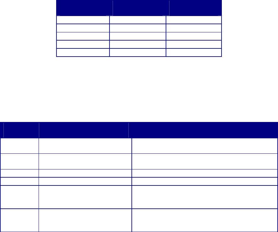
2-14 / Installation & Operation CI-ControlWave Express
Table 2-4 - RS-485 Network Connections
(see Table 2-3C ControlWave Express RS-485 Port Pin # Assignments)
From
Master
To 1st
Slave
To nth
Slave
TXD+ RXD+ RXD+
TXD− RXD− RXD−
RXD+ TXD+ TXD+
RXD− TXD− TXD−
GND/ISOGND*
GND/ISOGND* GND/ISOGND*
* ISOGND with Isolated RS-485 Ports Only!
Note: Pins 1, 2, 3, 4 & 9 of BBI Series 3305, 3310, 3330, 3335 & 3340 RTU/DPC RS-485 Comm.
Ports are assigned as follows: 1 = TXD+, 2 = TXD-, 3 = RXD+, 4 = RXD- & 9 = ISOGND.
Table 2-5 - CPU/System Controller Bd. Switch SW3 Assignments
RS-485 Loopback & Termination Control for COM3
SWITCH
#
RS-485 Function
Switch ON
Setting
SW3-1 TX+ to RX+ Loopback/2-Wire ON – 2-Wire Operation or Loopback Enabled
OFF – 4-Wire Operation & Loopback Disabled
SW3-2 TX− to RX− Loopback/2-Wire ON – 2-Wire Operation or Loopback Enabled
OFF – 4-Wire Operation & Loopback Disabled
SW3-3 100 Ohm RX+ Termination ON – End Nodes Only
SW3-4 100 Ohm RX− Termination ON – End Nodes Only
SW3-7 RX+ Bias (End Nodes/Node)
ON – 4-Wire = Both End Nodes
2-Wire = One End Node Only
OFF – No Bias
SW3-8 RX− Bias (End Nodes/Node)
ON – 4-Wire = Both End Nodes
2-Wire = One End Node Only
OFF – No Bias
SW3-5 & SW3-6 Not Used
2.3.3.4 Ethernet Port
ControlWave Express CPU/System Controller Boards can contain one Ethernet Port that
utilizes a 10/100Base-T RJ-45 modular connector (J1) and typically provides a shielded
twisted pair interface to an Ethernet Hub.
A typical Ethernet Hub provides eight (8) 10/100Base-T RJ-45 Ports (with Port 8 having the
capability to link to another Hub or to an Ethernet communications port). Both ends of the
twisted pair Ethernet cable are equipped with modular RJ-45 connectors. These cables have
a one-to-one wiring configuration as shown in Figure 2-8. Table 2-6 provides the
assignments and definitions of the 8-pin 10/100Base-T connector.
It is possible to connect two nodes in a point-to-point configuration without the use of a
Hub. However, the cable used must be configured such that the TX+/- Data pins are
connected to the RX+/- Data pins (swapped) at the opposite ends of the cable (see Figure 2-
7).
The maximum length of one segment (CPU to Hub) is 100 meters (328 feet). The use of
Category 5 shielded cable is recommended.
Click here to return to Table of Contents
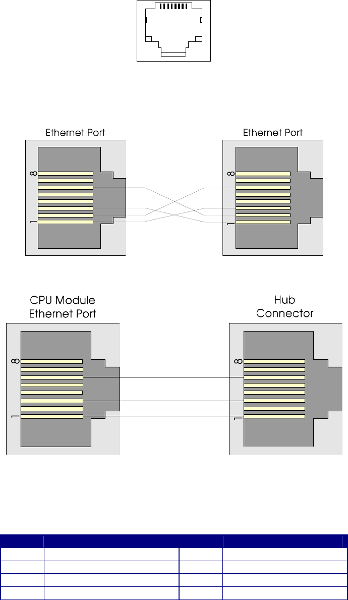
CI-ControlWave Express Installation & Operation / 2-15
18
Looking into
receptacle
Figure 2-6 - RJ-45 Connector (Ethernet Port) J1 on CPU/System Controller Board
Figure 2-7 - Point-to-Point 10/100Base-T Ethernet Cable
Figure 2-8 - Standard 10/100Base-T Ethernet Cable
(CPU/System Controller Board to Hub)
Table 2-6 - Ethernet 10/100Base-T Pin Assignments
Pin # Description Pin # Description
1 Transmit Data+ (Output) 5 Not Connected
2 Transmit Data- (Output) 6 Receive Data- (Input)
3 Receive Data+ (Input) 7 Not Connected
4 Not Connected 8 Not Connected
Note: TX & RX are swapped at Hub’s.
Click here to return to Table of Contents
2-16 / Installation & Operation CI-ControlWave Express
2.3.4 I/O Wiring
ControlWave Express RTUs are provided with card edge terminal blocks that accommodate
field wiring. Wiring is routed into the enclosure/chassis through a slot in the removable
card edge cover.
2.3.4.1 I/O Wire Connections
ControlWave Express RTUs utilize terminal blocks equipped with compression-type
terminals that accommodate up to #16 AWG wire. A connection is made by inserting the
wire’s bared end (1/4” max) into the clamp beneath the screw and securing the screw. The
wire should be inserted fully so that no bare wires are exposed to cause shorts. If using
standard wire, tin the bare end with solder to prevent flattening and improve conductivity.
Allow some slack in the wires when making terminal connections. The slack makes the
connections more manageable and minimizes mechanical strain on the terminal blocks.
Field I/O Wiring is supported by card edge Terminal Block Connectors as follows:
2.3.4.2 Shielding and Grounding
The use of twisted-pair, shielded and insulated cable for I/O signal wiring will minimize
signal errors caused by electromagnetic interference (EMI), radio frequency interference
(RFI) and transients. When using shielded cable, all shields should only be grounded at one
point in the appropriate system. This is necessary to prevent circulating ground current
loops that can cause signal errors.
Process I/O Board I/O Connections
Non-isolated Analog Input Connection (Section 2.3.4.6)
Non-isolated Analog Output Connection (Section 2.3.4.7)
Dedicated Non-isolated Digital Input Connection (Section 2.3.4.3)
Dedicated Non-isolated Digital Output Connection (Section 2.3.4.4)
Selectable Non-isolated Digital Input/Output Connection (Section 2.3.4.5)
Non-isolated High Speed Counter Input Connector (Section 2.3.4.8)
CPU/System Controller Board I/O Connections
Non-isolated Pulse Input Connection (Section 2.3.4.9)
2.3.4.3 Dedicated Non-isolated Digital Inputs
Process I/O Board Terminal Block connector TB2 provides interface to 4 dedicated non-
isolated Digital Inputs DIs). All Digital Inputs support dry contact inputs that are pulled
internally to 3.3 Vdc when the field input is open. Source current for DI#1 through DI#4 is
switch selectable for 60uA or 2mA from the 3.3V supply (SW1-3 ON = 2mA, OFF = 60uA).
Note: SW1-3 sets all DIs and all HSCs (for DI5, DI6, HSC1 & HSC2 SW1-3 ON = 2.2mA
and SW1-3 OFF = 200uA). 15 millisecond input filtering protects against contact bounce.
2.3.4.3.1 Dedicated Digital Input Configurations
Terminal Block TB2 supports four non-configurable DIs. Each DI provides a 60uA or 2mA
source current from 3.3Vdc. Switch SW1-3 must be set to establish the DI source current for
DI#1 through DI4 (SW1-3 ON = 2mA, OFF = 60uA) as well as DI5 & DI6 (SW1-3 ON =
2.2mA, OFF = 200uA). Field wiring assignments are provided in Figure 2-9.
Click here to return to Table of Contents
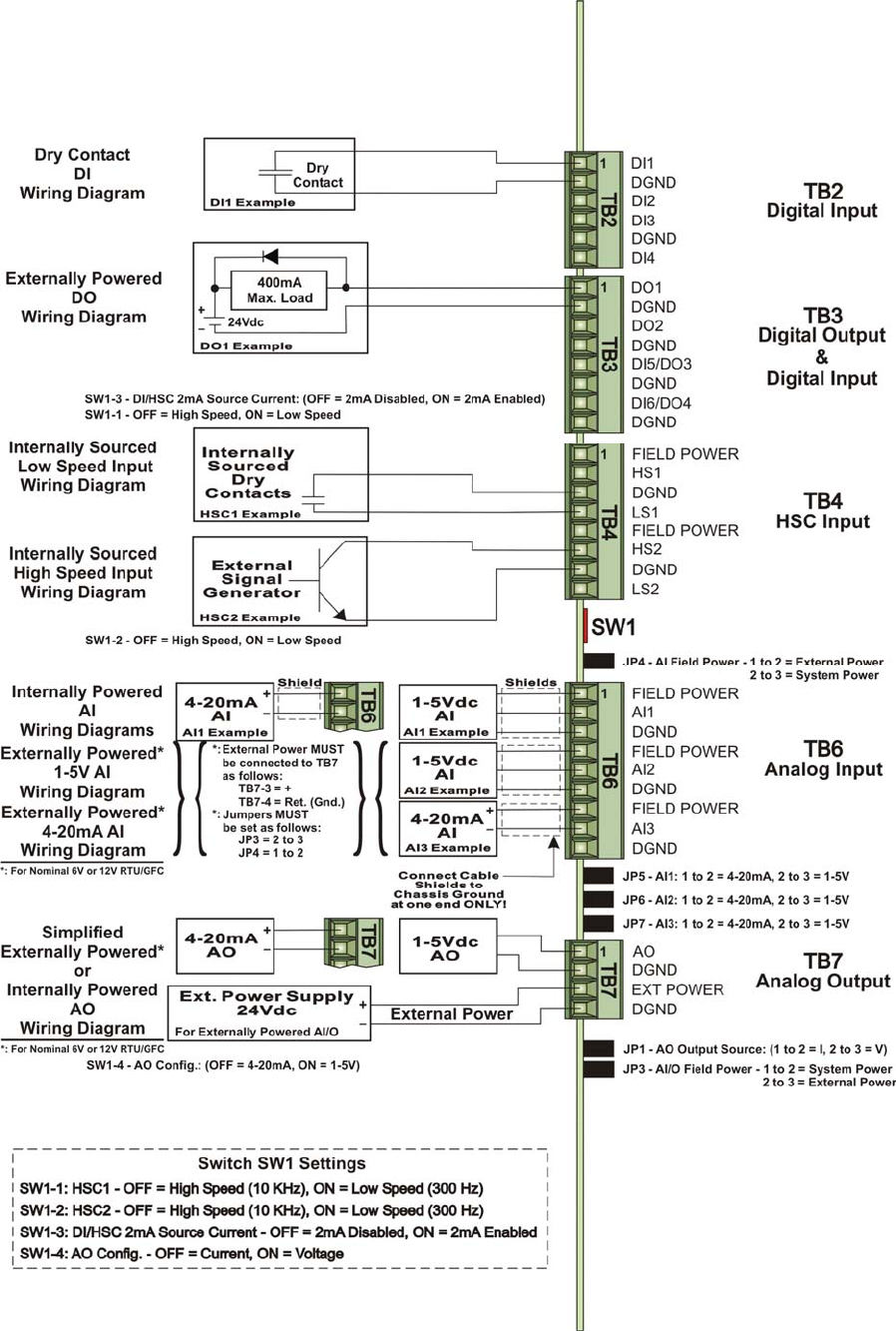
CI-ControlWave Express Installation & Operation / 2-17
Figure 2-9 – Process I/O Board Field I/O Wiring Diagrams
Click here to return to Table of Contents
2-18 / Installation & Operation CI-ControlWave Express
2.3.4.4 Dedicated Non-isolated Digital Outputs
Process I/O Board Terminal Block connector TB3 provides interface to 2 dedicated non-
isolated Digital Outputs (DOs) and two selectable DI/Os. Digital Outputs have a 30V
operating range and are driven by Open Drain MOSFETs that provide 400 mA (Max.) at
30Vdc. The maximum output frequency is 20 Hz. Transorbs (30Vdc) provide surge
suppression between each signal and ground.
2.3.4.4.1 Dedicated Digital Output Configurations
Process I/O Board Terminal Block connector TB3 supports two non-configurable externally
powered DOs. Open drain MOSFETs associated with each DO can sink 400mA. Field
wiring assignments are provided in Figure 2-9.
2.3.4.5 Selectable Non-isolated Digital Inputs/Outputs
TB3 supports 2 user-selectable Digital Inputs/Outputs. These DI/Os may be unused or
individually user wired as desired, i.e., both DI, both DO, one DI and/or one DO. Their
operation depends on how they are wired, i.e., DI or DO. DI/Os are rated identically to the
DIs and DOs.
2.3.4.5.1 Selectable Digital Input/Output Configurations
Process I/O Board Terminal Block connector TB3 supports two user selectable DI/DOs.
When wired for DI operation, each DI provides a 200uA or 2.2mA source current from
3.3Vdc. Switch SW1-3 must be set to establish the DI source current for DI 5 & 6 (SW1-3
ON = 2.2mA, OFF = 200uA). When wired for DO operation, the Open Drain MOSFET
associated with each DO can sink 400mA @ 30Vdc. Field wiring assignments are provided
in Figure 2-9.
2.3.4.6 Non-isolated Analog Inputs
Process I/O Board Terminal Block connector TB6 provides interface to three single-ended
Analog Inputs. Three field terminals are assigned for each Analog Input, i.e., Field Power,
AI# and DGND). AI field power applied to each Analog Input (controlled via Jumper JP4)
can be supplied by the system power (bulk input supply) or an external 24V power source.
Each AI can be individually configured for 4-20mA or 1-5 operation (via Jumpers JP5 for
AI1, JP6 for AI2 and JP7 for AI3). Note: When AI Field Power Jumper JP4 is set in
position 1 to 2, an external 24Vdc power source such as the ControlWave Loop
Power Supply (see PIP-ControlWaveLS) will be required to power the Analog
Inputs. When JP4 is set in position 2 to 3, the three Analog Inputs are powered by
the system, i.e., the bulk input power applied to across TB1-3 (Power In+) and
TB1-4 (GND) on the CPU/System Controller Board.
AIs are supplied with a two hertz low pass filter and surge suppression (via 30Vdc Tran-
sorbs). The Analog Inputs are self-calibrating.
2.3.4.6.1 Analog Input Configurations
AI circuits are supported by Configuration Jumpers that accommodate configuration of
each of the three Analog Inputs (see Table 2-7). Analog Input can be individually configured
for 1-5V or 4-20mA operation. Field wiring assignments are provided in Figure 2-9.
Click here to return to Table of Contents

CI-ControlWave Express Installation & Operation / 2-19
Note:
Cable shields associated with AI wiring should be connected to the ControlWave Express
Chassis Ground. Multiple shield terminations will require a user supplied copper ground
bus. This ground bus must be connected to the ControlWave Express Chassis Ground
(using up to a #4 AWG wire size) and must accommodate a connection to a known good
Earth Ground (in lieu of a direct connection from the ControlWave Express Chassis
Ground) and to all AI cable shields. Shield wires should use an appropriate Terminal Lug
and should be secured to the copper bus via industry rugged hardware (screw/bolt, lock
washer and nuts).
Table 2-7 - Analog Input Circuitry Jumper Assignments
Jumper Purpose Notes
JP4 AI Field Power Pins 1-2 installed = External Power
Pins 2-3 installed = System Power
JP5 – JP7 Configures AI1 through
AI3 (respectively)
Pins 1-2 installed = 4-20mA AI
Pins 2-3 installed = 1-5V AI
2.3.4.7 Non-isolated Analog Output
Process I/O Board Terminal Block connector TB7 provides interface to 1 Analog Output.
The AO channel can be configured for an internal or external power source via jumper JP3.
External power can range from +11 to + 30 Vdc. It should be noted that Analog Output
circuitry associated with 6V units MUST be configured for external power
operation.
Analog Output circuitry consists of a 12-bit resolution Digital to Analog Converter, a V to I
circuit and a V to V circuit. 4 to 20mA or 1-5V operation is configured via SW1-4. The AO
channel is self-calibrating.
2.3.4.7.1 Analog Output Configurations
The Analog Output circuit utilizes two Configuration Jumpers that accommodate 1-5V or 4-
20mA AO operation (JP1) and AO Power selection (JP3), i.e., system power (nominally 12
or 24 Vdc) or external power (11 - 30Vdc). Switch SW1-4 is also used to select calibration
data for the AO’s current/voltage operation. The maximum external load that can be
connected to the 4-20mA output is 250 ohms (with an external 11V power source) or 650
ohms (with an external 24V power Source). The maximum external load current for the 1-
5V output is 5mA (with an external 11 to 30 V power source). AO operation requires either
an 11 to 30Vdc power source (connected to TB7-3 and TB7-4) or the unit’s power supply
(nominally 12 or 24 Vdc). Note: External power can be supplied by Bristol
ControlWave Loop Power Supply which supplies a regulated and isolated +24Vdc
(see PIP-ControlWaveLS).
Table 2-8 - Analog Output Circuitry Jumper/Switch Assignments
Jumper/
Switch
Purpose Notes
JP1 AO1 Field Output Source Config. Pins 1-2 installed = 4-20 mA AO
Pins 2-3 installed = 1-5V AO
JP3 A/IO Power Pins 1-2 installed = System Power
Pins 2-3 installed = External Power
SW1-4 AO Field Output Source Config. SW1-4 ON = Voltage
SW1-4 OFF = Current
Click here to return to Table of Contents
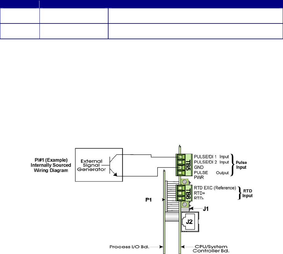
2-20 / Installation & Operation CI-ControlWave Express
2.3.4.8 Non-isolated High Speed Counter/Digital Inputs
Process I/O Board Terminal Block connector TB4 provides the interface to two internally-
sourced single-ended High Speed Counter/Digital Inputs (HSC/DIs). All Input circuits have
surge suppression and signal conditioning. HSC inputs are switch-selectable (SW1-1 for
HSC1 & SW1-2 for HSC2) for high frequency (10 kHz) or low frequency (300 Hz).
High Speed Counter/Digital inputs are sourced from 3.3Vdc and are switch selectable for a
source current of 200uA or 2.2mA (SW1-3 ON = 2.2mA, OFF = 200uA). Note: SW1-3 sets all
DIs and all HSCs.
2.3.4.8.1 High Speed Counter Configurations
A total of 2 HSC inputs with surge protection are provided. HSC Configuration Switches
must be set per Table 2-9.
Table 2-9 - Non Isolated HSC/DI Switch Assignments
Switches Purpose Notes
SW1-1
SW1-2
Configures HSC1
Configures HSC2
OFF = High Frequency (10 kHz)
ON = Low Frequency (300 Hz)
SW1-3 HSC Source Current OFF = 200uA Source Current
ON = 2.2mA Source Current
2.3.4.9 Non-isolated Pulse Counter/Digital Inputs
CPU/System Controller Edge connector TB5 provides the interface to two non-configurable
Open Collector Pulse Counter/Digital Inputs (Pulse 1 and Pulse 2). Pulse Counters act like
high speed counters but cannot be used with contact relays because they lack contact
debounce circuitry. Signal conditioning circuitry provides 20 microsecond filtering. Each
Pulse Counter/Digital input circuit has surge suppression which consists of a 16V transorb
between signal and ground. Pulse Counter/Digital Inputs are field driven by open collector
circuits and are sourced for 3.3V (internally) with a 200uA source current. Maximum input
frequency for each Pulse Counter/Digital Input circuit is 10 kHz. Figure 2-10 shows the
Open Collector Wiring arrangement.
Figure 2-10 - Pulse Input Wiring Diagram
Click here to return to Table of Contents
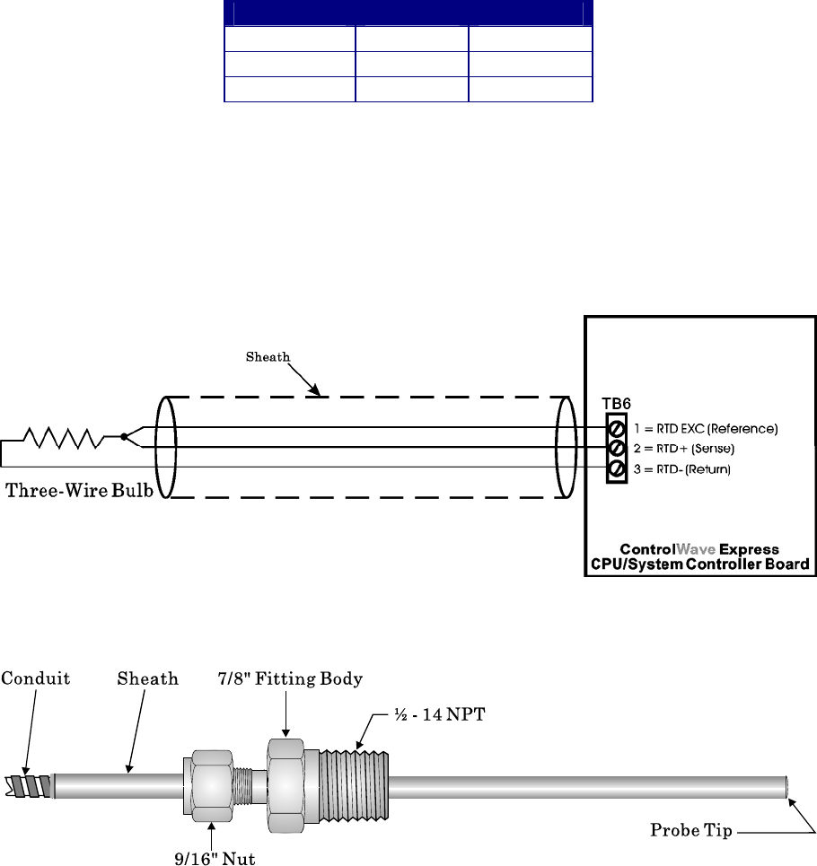
CI-ControlWave Express Installation & Operation / 2-21
2.3.5 RTD Wiring
A 3-wire RTD may be provided with the ControlWave Express (equipped with a 14MHz
CPU/System Controller Board). Connector TB6 on the CPU/System Controller Board
accommodates a removable three-wire Terminal Block (TB6). This connector accommodates
a 100-ohm platinum bulb using the DIN 43760 curve. ControlWave Express RTUs use the
common three-wire configuration. In this configuration, the Return lead connects to RTD-
and the two junction leads (Sense and Excitation), connect to RTD+ and RTD EXC.
Connection between the RTD and CPU/System Controller Board is wired per Table 2-10
and Figure 2-11.
Table 2-10 - RTD Connections to CPU/System Controller Board Connector TB6
TB6 Pin Signal Function
1 RTD EXC Reference
2 RTD+ Sense
3 RTD- Return
Never ground the RTD Cable Shield at both ends or allow it to come in contact with
metallic/conductive conduit as multiple ground paths could cause RTD input errors.
To install the RTD Probe, screw the Fitting Body into the thermowell with a 7/8”open-end
wrench. While applying pressure against the sheath to force the Tip of the RTD Probe into
the bottom of the thermowell (so that the Probe Tip is in contact with the thermowell),
tighten the Nut (9/16” open-end wrench) against the 7/8” Fitting Body (see Figure 2-12).
Figure 2-11 - 3-Wire RTD Temperature Input Wiring
Figure 2-12 - RTD Probe Installation/Removal Diagram
Click here to return to Table of Contents
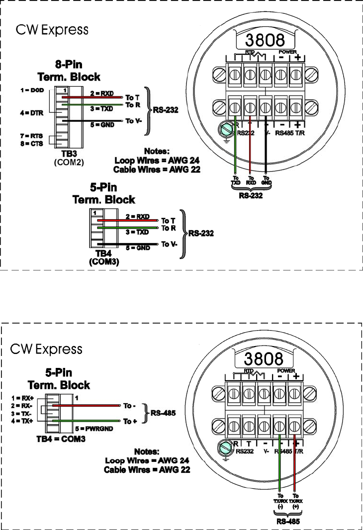
2-22 / Installation & Operation CI-ControlWave Express
2.3.6 Connection to a Model 3808 Transmitter
A Model 3808 Transmitter (Digital) can be interfaced to a ControlWave Express via an RS-
232 or an RS-485 communication scheme. Communication schemes and cable lengths
determine the type of communication port utilized. In general RS-232 communications are
utilized when the Model 3808 Transmitter is situated within 25 feet of the ControlWave
Express, i.e., for local communications. Communications can be achieved with transmitters
up to 4000 feet away (remote communications) via the RS-485 scheme.
Figure 2-13 - 3808 Transmitter to ControlWave Express
RS-232 Comm. Cable Diagram
Note: For Loopback & Termination Control:
Use SW3 on CPU/System Controller Board to configure COM3.
Figure 2-14 - 3808 Transmitter to ControlWave Express RS-485 Comm. Cable
Click here to return to Table of Contents
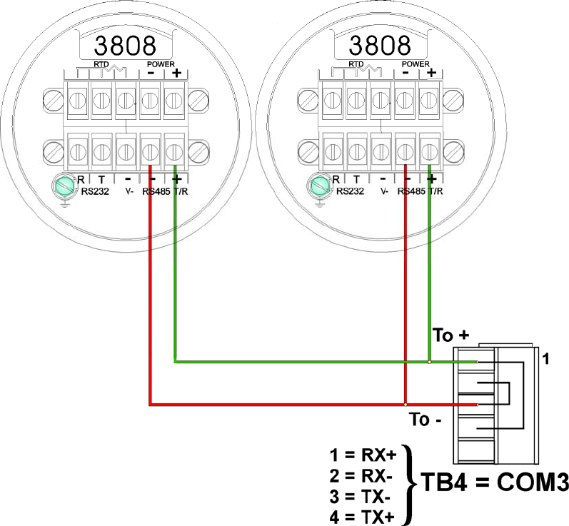
CI-ControlWave Express Installation & Operation / 2-23
Figure 2-15 - ControlWave Express to 3808s - RS-485 Network Diagram
Figures 2-13 and 2-14 detail the RS-232 and RS-485 wiring connections required between
the ControlWave Express and the Model 3808 Transmitter.
Up to two Model 3808 Transmitters can be connected to a ControlWave Express via a half-
duplex RS-485 Network. An illustration of this network is provided in Figure 2-15.
2.3.7 Power Wiring & Distribution
Primary Power is user supplied applied to Connector TB1 of the CPU/System Controller
Board (TB1-3 = Power In + & TB1-4 = GND) and is based upon the type of CPU/System
Controller Board as follows:
• 14MHz Ultra Low Power CPU: Nominal +6Vdc (+5.4V to +16.0V) or Nominal +12Vdc
(+11.4V to +16V) bulk input supply.
• 33MHz Low Power CPU: Nominal +12Vdc (+11.4V to +16.0V) or Nominal
+24Vdc (+21.8V to +28V) bulk input supply.
• 33MHz with Ethernet CPU: Nominal +12Vdc (+11.4V to +16.0V) or Nominal
+24Vdc (+21.8V to +28.0V) bulk input supply.
Two other power interface connections are provided on 14 MHz Ultra Low Power and 33
MHz Low Power CPU/System Controller Boards and function as follows:
Click here to return to Table of Contents

2-24 / Installation & Operation CI-ControlWave Express
• TB1-1 - Solar Power In + (TB1-2 = GND ) (GND = −)
• TB1-5 - Auxiliary Power Out + - for External Radio/Modem (TB1-6 = GND) (GND = −)
A secondary power input is available at connector TB2:
• TB2-1 – Input
• TB2-2 – Ground
ControlWave Express Terminal Blocks utilize compression-type terminals that
accommodate up to #16 AWG wire. A connection is made by inserting the wire’s bared end
(1/4” max) into the clamp adjacent to the screw and then securing the screw. The wire
should be inserted fully so that no bare wires are exposed to cause shorts. If using standard
wire, tin the bare end with solder to prevent flattening and improve conductivity. Allow
some slack in the wires when making connections. The slack makes the connections more
manageable and helps to minimize mechanical strain on the terminal blocks.
2.3.7.1 Bulk Power Supply Current Requirements
ControlWave Express RTUs are equipped with a CPU/System Controller Board that accepts
either 6/12Vdc or 12/24Vdc Bulk Power input. The maximum current required for a
particular ControlWave Express can be estimated as follows:
Bulk +6/12/24Vdc Supply Current = CPU/System Controller Board (with options) +
Process I/O Board + LCD Display Keypad + Optional External Modem/Radio
Table 2-11A - ControlWave Express Base Assembly Power Requirements
(for 14MHz Ultra Low Power CPU)
COMPONENTS Bulk 12Vdc
Supply
Bulk 6Vdc
Supply
CPU + Process I/O + LCD
W/O Field Supply & with
AO Output under range:
5mA
7.0mA
Table 2-11B - ControlWave Express Base Assembly Power Requirements
(for 33MHz CPU - With/Without Ethernet)
COMPONENTS Bulk 12Vdc
Supply
Bulk 24Vdc
Supply
CPU + Process I/O + LCD
(without Ethernet)
W/O Process I/O Bd.:
10mA
W/O Process I/O Bd.:
10mA
CPU + Process I/O + LCD
(with Ethernet)
W/O Process I/O Bd.:
80mA
W/O Process I/O Bd.:
47mA
Note: Current consumptions provided in Tables 2-11A/B are based on typical
application loads. For 3808 power consumption refer to CI-3808.
This summation will accommodate steady state current draw. Table 2-11A and 2-11B
provide detailed steady state power current requirements for each ControlWave Express
configuration. Note: In the case of an external modem/radio, the unit’s manufacturer
provides power consumption specifications.
Click here to return to Table of Contents
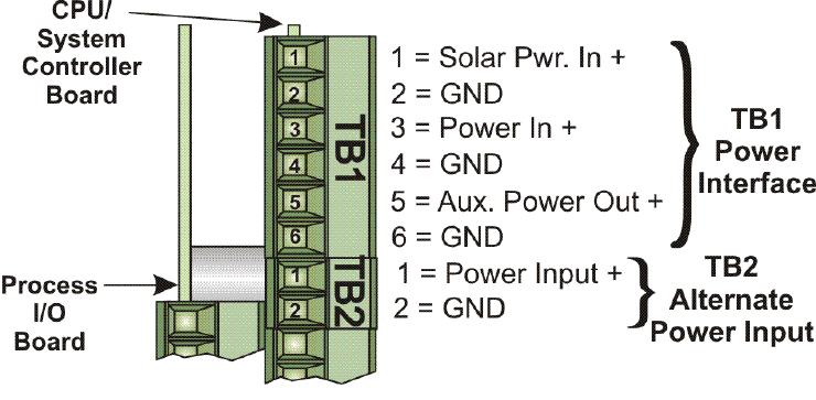
CI-ControlWave Express Installation & Operation / 2-25
2.3.7.2 Power Wiring
One Bulk DC supply can be connected to the ControlWave Express CPU/System Controller
Board. The Bulk DC supply (nominally +6Vdc, +12Vdc or +24Vdc) connected to TB1-3
(Power In +) and TB1-4 (GND -) is converted, regulated and filtered by the CPU/System
Controller Board to produce +3.3Vdc. This CPU/System Controller Bd. circuit is fused at
3.5A (F3). Depending on the version of the CPU/System Controller Board, the unit’s input
power operating range will vary as follows:
• Nominal +6Vdc input source operating range: (+5.4Vdc to +16.0Vdc)
• Nominal +12Vdc input source operating range: (+11.4Vdc to +16.0Vdc)
• Nominal +24Vdc input source operating range: (+21.8Vdc to +28.0Vdc)
An alternate power connection is available at connector TB2, intended for use if power is
not available through TB1. Bulk DC power would be connected to TB2-1 (Power Input) and
TB2-2 (GND).
Figure 2-16 - CPU/System Controller Board (TB1 & TB2) Power Wiring
Note: Solar Power In+ and Aux. Power Out+ not available on CPUs with Ethernet
2.3.7.3 ControlWave Express System Grounding
ControlWave Express Enclosures are not provided with a Ground Lug. Instead, the user
utilizes one or more mounting screws to secure a ground cable to the unit. A ground wire
(#4 AWG Max. wire size) must be run between the enclosure via one or more mounting
screws (see Figure 2-1) and a known good Earth Ground. The following considerations are
provided for the installation of ControlWave Express system grounds (see S1400CW):
• Earth Ground wire size should be #4 AWG. It is recommended that stranded copper wire
is used and that the length should be as short as possible.
• This ground wire should be clamped or brazed to the Ground Bed Conductor (that is
typically a stranded copper AWG 0000 cable installed vertically or horizontally).
• The wire end that is to be fastened to the ControlWave Express should be crimped to a
Terminal Ring/Lug and soldered. Note: Use a high wattage Soldering Iron.
• The ground wire should be run such that any routing bend in the cable has a minimum
radius of 12-inches below ground and 8-inches above ground.
Click here to return to Table of Contents
2-26 / Installation & Operation CI-ControlWave Express
2.3.8 Operation of the Lithium Backup Coin-cell Battery
CPU/System Controller Boards are equipped with a Coin-cell Socket (S1) that
accommodates a 3.0V, 300 mA-hr lithium coin cell. A supervisory circuit on the
CPU/System Controller Board is used to switch to battery power when the regulated 3.3Vdc
VCC falls out of specification. The CPU/System Controller Board switches the battery
voltage to the VBAT3.3 hardware signal, which provides backup power for the real-time
clock (RTC) and the system SRAM on the CPU Module.
The system SRAM has a standby current draw of 20uA maximum for each part. For a unit
containing 2MB of SRAM, a worst-case current draw of 42uA allows a battery life of
approximately 9000 hours.
Jumper W3 on the CPU/System Controller Board must be installed on terminals 1 and 2 to
enable the battery. For maximum shelf life, the battery may be isolated from the circuit by
install Jumper W3 on terminals 2 and 3.
CPU/System Controller Boards are shipped with the Lithium backup battery installed. To
remove the backup battery, pry up the Battery Securing Tab on the Coin-cell Battery
Socket and then remove the battery using a pair of tweezers or needle-nose pliers. Install
the replacement battery. Note: This step will not be required until units have been in
operation for an extended period of time (normally many years) as the battery life is
approximately 9000 hours of backup service. (Power is drawn from the battery when the
unit looses power).
NOTE:
If the Lithium backup battery is disconnected or removed when power is off the
contents of SRAM (on the CPU/System Controller Board) will not be retained.
Once a Lithium backup battery has been removed, do not install a replacement
battery for at least one minute unless SW2-5 on the CPU/System Controller Board
has been set OFF.
2.4 OPERATIONAL DETAILS
ControlWave Express RTUs are shipped from the factory with firmware that allows the
unit to be configured in conjunction with an IEC 61131, application program. This section
provides information as follows:
- Steps required to download the application and place the unit into ‘Run’ mode.
- Steps required to download system firmware.
- Operation of the CPU/System Controller Board’s Mode Switch (SW1)
- Soft Switch Configurations and Communication Ports
Operational details on ControlWave Express LEDs (and optional LCD Displays) and use of
the Bristol WINDIAG program for fault isolation are provided in Chapter 3.
2.4.1 Downloading the Application
Any ControlWave Express must have a configured ControlWave project (application) before it
can be placed into operation. For units not shipped with a standard application, this will
require connection of the ControlWave Express to a PC running ControlWave Designer and
OpenBSI software. Configuration of the application must be performed by an individual
Click here to return to Table of Contents
CI-ControlWave Express Installation & Operation / 2-27
familiar with the various programming tools. The following software user documentation is
referenced:
Getting Started with ControlWave Designer Manual - D5085
ControlWave Designer Reference Manual - D5088
Open BSI Utilities Manual - D5081
Web_BSI Manual - D5087
ControlWave Designer Programmer’s Handbook – D5125
An application download can be initiated from ControlWave Designer, or from the OpenBSI
1131 Downloader.
1. Make sure that the CPU/System Controller Board’s Mode Switch (SW1) is set in ‘Local
Mode,’ i.e., SW1-1 set to the OFF position and SW1-2 set to the ON position.
NOTE:
From the factory, COM1 defaults to 115.2 kbd (RS-232) using the BSAP
Protocol. Do not connect COM1 to a PC unless the PC’s RS-232 port in question
has been configured for BSAP operation.
2. Once the ControlWave Express project has been defined, communications and
configuration parameters have been set, perform the download from ControlWave
Designer (see D5088 - chapter 11) or from the Open BSI 1131 Downloader (see D5081 -
Chapter 7).
3. After the download has been completed leave the CPU/System Controller Board’s Mode
Switch (SW1) in the ‘Local Mode’ position.
2.4.2 Upgrading ControlWave Express Firmware
ControlWave Express CPUs ship from the factory with system firmware already installed.
If an upgrade of the system firmware is required, use one of the procedures below to
download the new or replacement firmware from the PC.
Upgrade of system firmware via LocalView FLASH Mode requires OpenBSI 5.1 (or newer).
If you have an older version of OpenBSI, FLASH upgrades are performed via
HyperTerminal. You will need a binary (*.BIN) system firmware file that is read as follows:
e1sxxxx.bin (for 14MHz CPUs) e3sxxxx.bin (for 33MHz CPUs) (where e1s or e3s is the
product code and xxxx is the release #). Upgrade of an unattended ControlWave Express
can be accomplished from a remote PC. This capability is introduced in Section 2.4.2.3.
2.4.2.1 Using LocalView to Upgrade ControlWave Express Firmware
NOTE:
Your ControlWave Express must be set to Recovery Mode ENABLE (ON) prior to
performing the FLASH upgrade, then set to Recovery Mode DISABLE (OFF) after
the upgrade. On ControlWave Express RTUs this is accomplished via the
CPU/System Controller Board’s Mode Switch SW1. Set SW1-3 to the ON position
for Recovery Mode. After setting SW1-3 to the ON position, turn power OFF and
then ON again.
A null modem cable (see Figure 2-5) must be connected to COM1 of the ControlWave
Express and to any RS-232 port on the associated PC. The PC’s RS-232 port used for this
Click here to return to Table of Contents
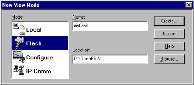
2-28 / Installation & Operation CI-ControlWave Express
purpose must be set to run at 115.2 Kbaud. ControlWave Express CPU Switch SW1,
position, 3 must be set ON.
Start LocalView, Choose FLASH, Enter A Name, Click on [Create]
Start LocalView by clicking on: Start Æ Programs Æ OpenBSI Tools Æ LocalView. The
New View Mode dialog box will appear (see Figure 2-17).
Figure 2-17 - Local View - New View Mode Menu
"Mode"
Choose 'Flash' for the mode.
"Name"
Enter a name for the View Mode File in the "Name" field.
"Location"
If you want to store the View Mode File in a directory other than that shown in the
"Location" field, enter the new location there, or use the [Browse] push button to find
the directory.
When the "Mode", "Name", and "Location" have been specified, click on the [Create] push
button to activate the Communication Setup Wizard.
Step 1 - Communication Setup
Choose the communication port you want in the What port would you like to use: field.
Click on the [Next] pushbutton to activate the next wizard.
Step 2 - Flash RTU Setup
In the Flash RTU Setup Wizard, you need not set the RTU type or local address, since these
are unused in this mode. Click on the [Next] push button to activate the Flash Data Setup
Wizard.
Click here to return to Table of Contents
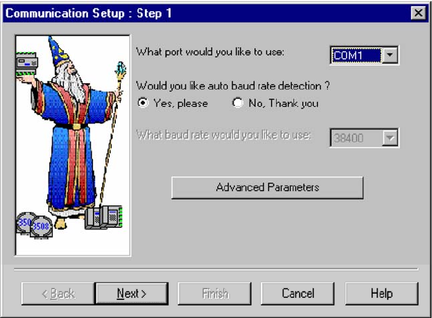
CI-ControlWave Express Installation & Operation / 2-29
Step 3 - Flash Data Setup
Complete the following fields in the Flash Data Setup Wizard:
"Please enter the name of the binary file to Flash"
To upgrade system firmware, you must specify the path and name of a binary (*.BIN)
file on your hard disk containing the firmware.
Click on [Finish] to install the specified BIN file in FLASH memory at the RTU.
Once the Flash download has begun, you will NOT be allowed to shut down LocalView,
unless you cancel the download, or it has been completed.
The progress of the Flash download will be displayed in the window. Any mismatch in file
versions, or if the type of .BIN file does not match the type of RTU, the download will be
aborted.
Figure 2-18 - Communication Setup: Step 1 Menu
Once the download has completed, set SW1-3 to the OFF position and then turn power OFF
and then ON again.
Click here to return to Table of Contents
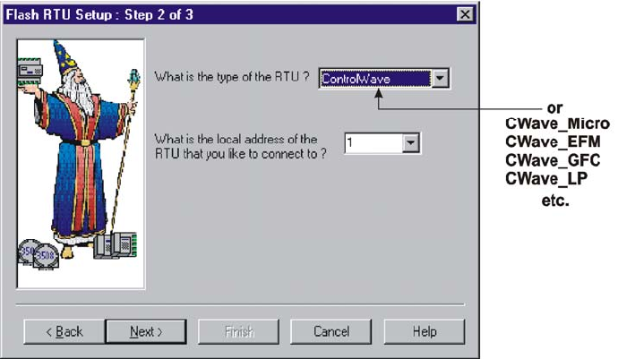
2-30 / Installation & Operation CI-ControlWave Express
Figure 2-19 - Flash RTU Setup Menu
Click here to return to Table of Contents
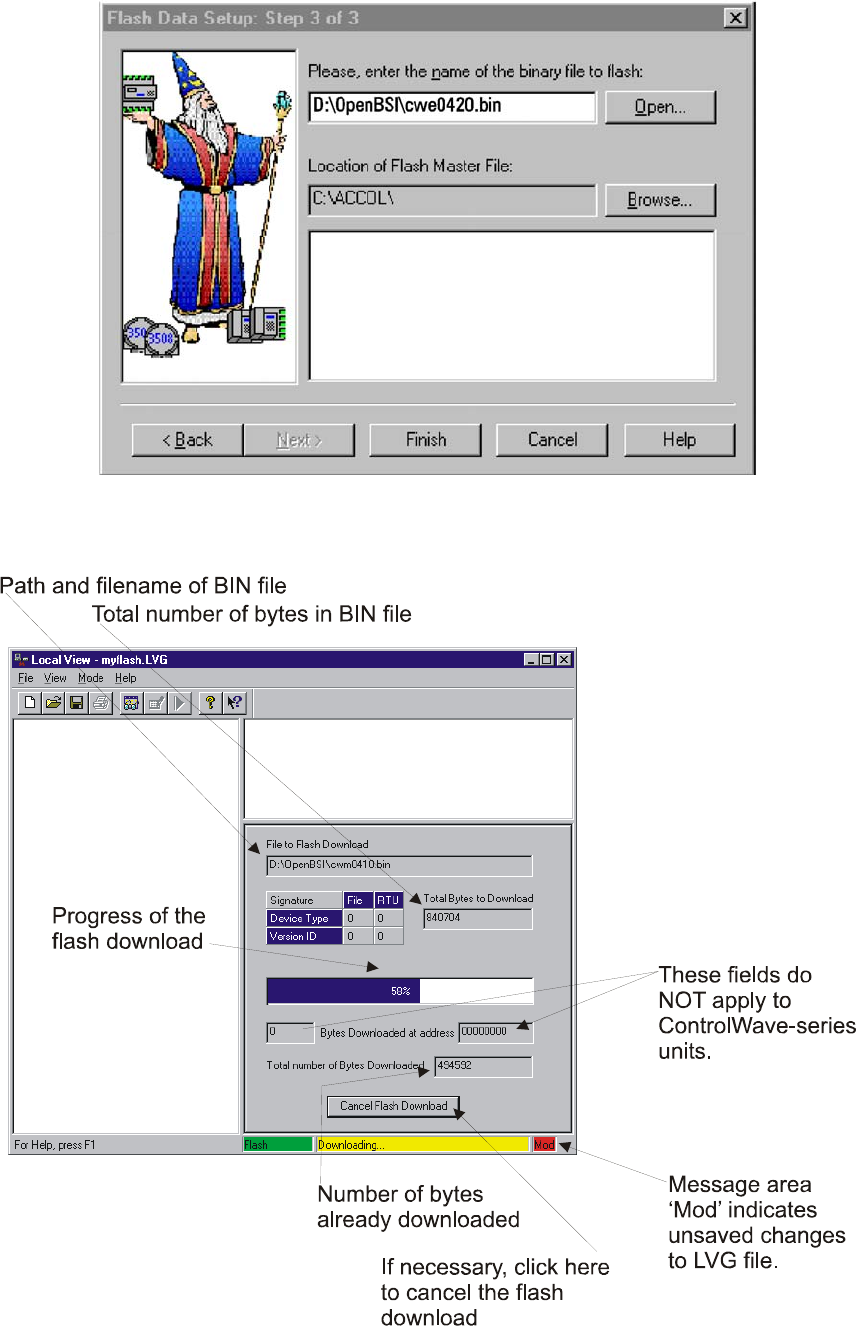
CI-ControlWave Express Installation & Operation / 2-31
Figure 2-20 - Flash Data Setup Menu
(Note: Substitute \e1sxxxxbin or \e3sxxxx for cwe04...)
Figure 2-21 - Local View Downloading System Firmware Menu
Click here to return to Table of Contents
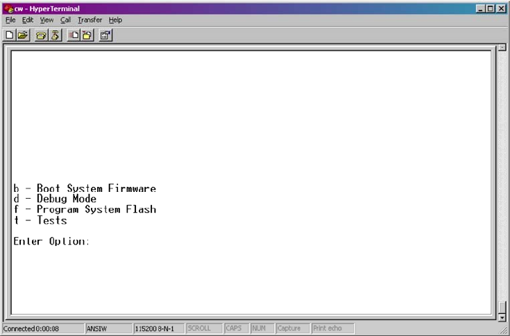
2-32 / Installation & Operation CI-ControlWave Express
2.4.2.2 Using HyperTerminal to Upgrade ControlWave Express Firmware
A half-duplex null modem cable (see Figure 2-5) must be connected to COM1 of the
ControlWave Express and to any RS-232 port on the associated PC. The PC’s RS-232 port
used for this purpose must be set to run at 115.2 Kbaud. ControlWave Express CPU/System
Controller Board Switch SW1, position, 3 must be set to the ON position.
1. If not already running, apply power to the associated PC.
2. Start the HyperTerminal program on the PC. Note: HyperTerminal is a Windows utility
program. In Windows XP, you can start HyperTerminal by clicking on Start Æ Programs
Æ Accessories Æ Communications Æ HyperTerminal. If using HyperTerminal for the
first time, set the communications properties (for the PC Port being utilized) via the
Properties Menu as follows: Bits per second: = 115200, Data bits: = 8, Parity: = None, Stop
bits: = 1, and Flow control: = None and then click OK.
3. Set the CPU/System Controller Board’s Mode Switch (SW1) for ‘Recovery Mode,’ i.e., set
CPU/System Controller Board Switch SW1-3 to the ON position.
4. Apply power to the ControlWave Express. The resident BIOS will initialize and test the
hardware, this process is referred to as POST (Power On Self Test).
Unless there is a problem System Status Code RECOV (Waiting in Recovery Mode) will
be posted to the Status LEDs on the CPU’s LED Board and to the optional LCD Display (if
present). Detection of a fault during POST will be posted on the LCD Display (if present)
and the Status LEDs on the CPU’s LED Board (see Table 2-12 and Figures 2-26 and 2-27).
Figure 2-22 - HyperTerminal Recovery Mode Menu
From the HyperTerminal Recovery Mode menu (Figure 2-22), press the ‘F’ key to enter
FLASH download. A message will be displayed warning that the FLASH is about to be
erased; press the ‘Y’ key at the prompt. The screen will display dots as the flash devices are
being erased; this could take a few minutes.
Click here to return to Table of Contents
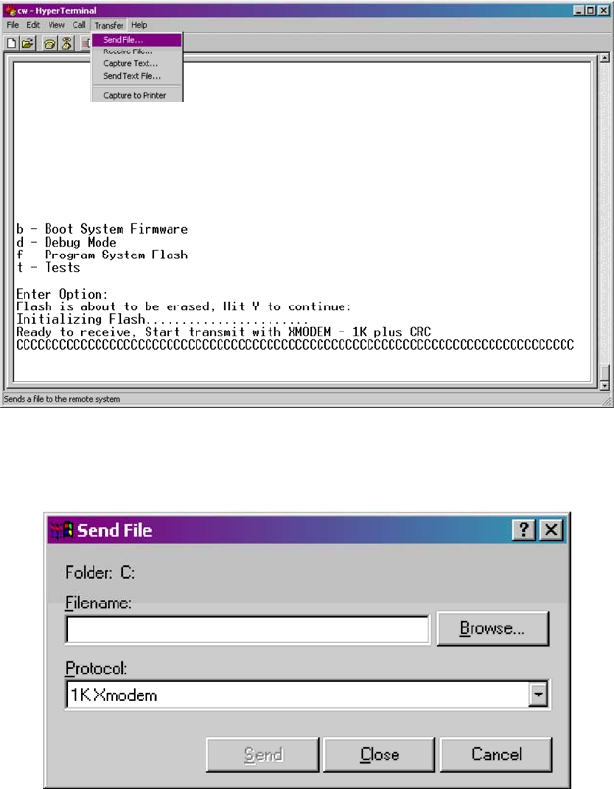
CI-ControlWave Express Installation & Operation / 2-33
5. When the FLASH is ready for download the letter C will be displayed on the screen. In
the HyperTerminal command bar click on Transfer and then Send File (see Figure 2-
23). In the Send File Dialog Box (see Figure 2-24), select “1KXmodem” for the protocol,
enter the filename of the appropriate .bin file in the format “e1sxxxxx.bin” or
“e3sxxxxx.bin” (where xxxxx varies from release to release). Click on the Send button to
start the download (see Figure 2-24). When the HyperTerminal Recovery Mode Menu of
Figure 2-22 appears, the download has completed.
6. Close the HyperTerminal program. The null modem cable connected between the
ControlWave Express and the PC can be removed if desired.
7. Set the CPU/System Controller Board’s Mode Switch (SW1) for ‘Local Mode,’ i.e., set SW1-
3 OFF. Then switch power OFF/ON.
Once the ControlWave Express is running its application load, status codes are posted to the
LCD Display (if present) and the Status LEDs on the CPU’s LED Board. These Status LED
Codes are listed in Table 2-12.
Figure 2-23 - HyperTerminal FLASH Download Menu
(Ready to Download) - (Transfer/Send File Selected)
Figure 2-24 - HyperTerminal Flash Download (Send File Dialog Box)
Click here to return to Table of Contents
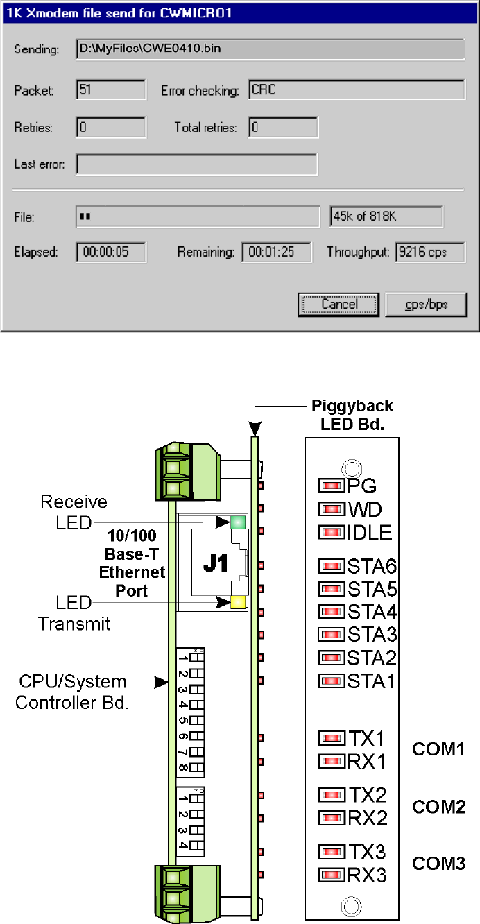
2-34 / Installation & Operation CI-ControlWave Express
Figure 2-25 - HyperTerminal FLASH Download (Download in Process)
(Note: Substitute \e1sxxxxbin or \e3sxxxx.bin for cwe04...)
Figure 2-26 - CPU/System Controller LEDs
(See Figure 2-27 and Table 2-12 for Status LED Definitions)
Click here to return to Table of Contents
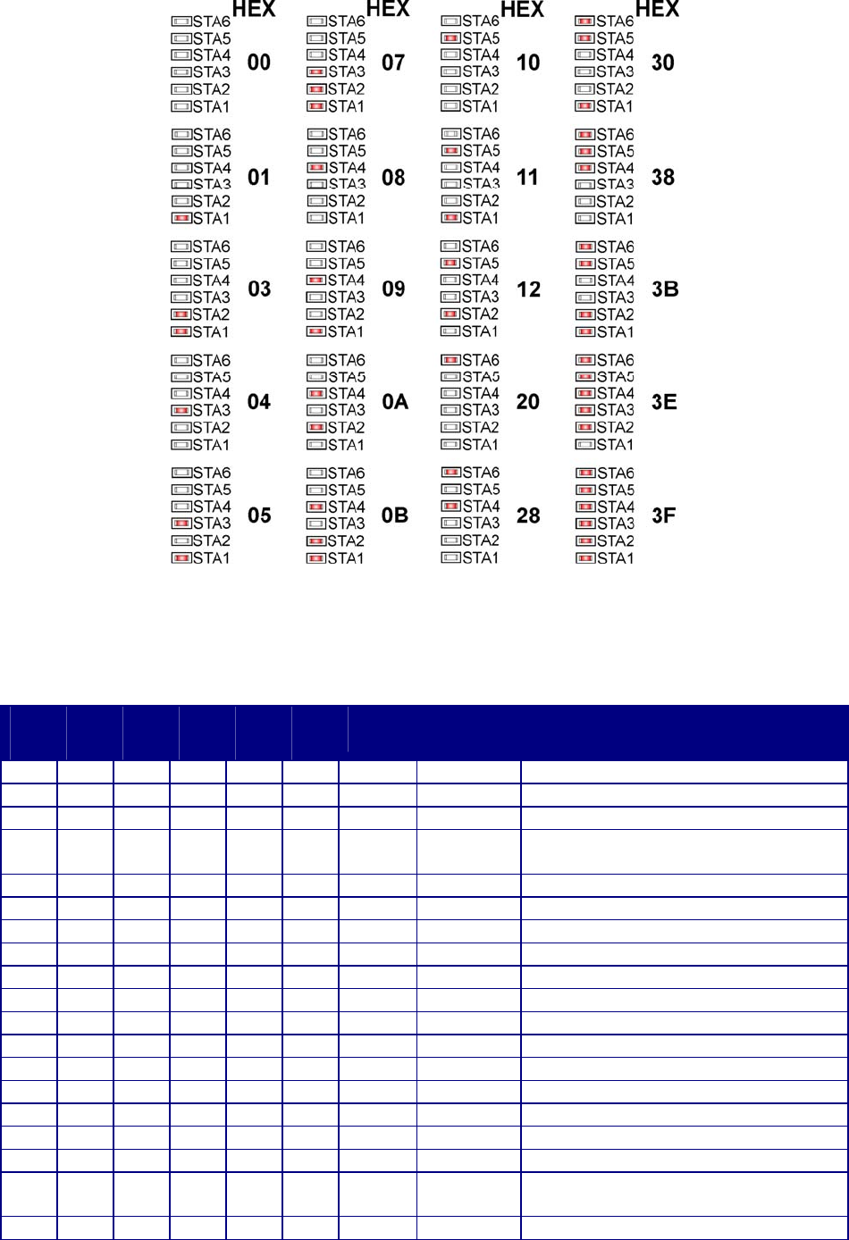
CI-ControlWave Express Installation & Operation / 2-35
Figure 2-27 - CPU/System Controller LED Board - LED Hexadecimal Codes
(See Table 2-12 for Definitions)
Table 2-12 - System Status Codes on LCD Display
& LEDs on CPU/System Controller Board’s LED Display Board.
LED
6
STA6
LED
5
STA5
LED
4
STA4
LED
3
STA3
LED
2
STA2
LED
1
STA1
Status
In Hex
LCD
Disp.
Indication
Definition
0 0 0 0 0 0 00 Blank Application Running
0 0 0 0 0 1 01 DIAG Unit in Diagnostic Mode
0 0 0 0 1 1 03 R DIAG Unit Running Diagnostics
0 0 0 1 0 0 04 FWXSU
M
Flash XSUM Error
0 0 0 1 0 1 05 DEVERR Error Initializing Application Device
0 0 0 1 1 1 07 FLASH Flash Programming Error
0 0 1 0 0 0 08 FACT Using Factory Defaults *
0 0 1 0 0 1 09 BATT Battery Failure Detected *
0 0 1 0 1 0 0A STRTUP Currently Loading the Boot Project
0 0 1 0 1 1 0B INIT System Initialization in Progress
0 1 0 0 0 0 10 RECOV Waiting in Recovery Mode
0 1 0 0 1 0 12 RAMERR Error Testing SRAM
1 0 0 0 0 0 20 STOP Application Loaded
1 0 1 0 0 0 28 HALT Stopped at a Break Point
1 1 0 0 0 0 30 NO APP No Application Loaded
1 1 1 0 0 0 38 BREAKP Running with Break Points
1 1 1 0 1 1 3B POWERD
Waiting for Power-down (after NMI)
1 1 1 1 1 0 3E UPDUMP
Waiting for Updump to be
Performed
1 1 1 1 1 1 3F NOTRUN Unit Crashed (Watchdog Disabled)
* = Flashed at startup
Click here to return to Table of Contents

2-36 / Installation & Operation CI-ControlWave Express
2.4.2.3 Remote Upgrade of ControlWave Express Firmware
It is possible to download system firmware into an unattended remote ControlWave
Express. This function can only be accomplished if CPU Board Switch SW2-6 (associated
with the unit in question) is set in the ON position (factory default). The procedure for
performing a remote download of system firmware is discussed in Appendix J of the Open
BSI Utilities Manual (document D5081). Note: Remote upgrade of ControlWave
Express Firmware requires Boot PROM version 4.7 or higher and System PROM
version 4.7 or higher.
2.4.3 Operation of the Mode Switch
The CPU/System Controller Board’s Mode Switch (SW1) is a four position DIP-Switch;
functions are listed in Table 2-12.
Table 2-12 - CPU/System Controller Bd. Mode Switch SW1 Assignments
Recovery Mode/Local Mode Control
SWITCH Function Setting
SW1-1/2 Recovery/Local Mode
Both ON or OFF = Recovery Mode
SW1 OFF & SW2 ON = Local Mode
SW1-3 Force Recovery Mode ON = Force Recovery Mode (via CW Console)
OFF = Recovery Mode disabled
SW1-4 LED Status ON = Enable All LEDs
OFF = Disable All LED except Watchdog (WD)
* = Note: Only the Switch SW1 settings listed in this table, have been tested.
Recovery Mode: Recovery Mode is used for either a firmware upgrade (see Section 2.4.2) or
a core updump (see Section 3.6).
Local Mode: Local Mode should be selected for normal running operations.
2.4.4 Soft Switch Configuration and Communication Ports
Firmware-defined soft switches that control many default settings for various system
operating parameters such as BSAP Local Address, EBSAP Group Number, three (3)
communication port parameters, etc., can be viewed and, if desired, changed via the Flash
Configuration Utility, which is accessible from LocalView, NetView, or TechView. When
connecting the ControlWave Express to the PC (local or network) for the first time you
should be aware of the communication port default parameter settings provided below (see
Figures 2-5 and 2-6). Note: Communication port factory defaults can be enabled anytime by
setting CPU Board Switch SW2-3 to the OFF position. CPU Switch SW2-8 must be set OFF
to run the WINDIAG program.
COM1: From the factory, RS-232 Communications Port COM1 defaults to 115.2 kbd (RS-
232) using the BSAP Protocol. Note: By setting CPU/System Controller Board
Switch SW2-8 OFF, the boot project will be prevented from running and the unit
will be placed into diagnostic mode. To test COM1 using the WINDIAG program, it
must not otherwise be in use. Connection to a PC requires the use of an RS-232
“Null Modem” cable (see Figure 2-5A/B).
COM2: From the factory, RS-232 Communications Port COM2 on the CPU/System
Controller Board defaults to 9600 baud, 8-bits, no parity, 1 stop bit,
BSAP/ControlWave Designer protocol operation. To test COM2 using the
Click here to return to Table of Contents
CI-ControlWave Express Installation & Operation / 2-37
WINDIAG program, it must not otherwise be in use. Note: CPU Switch SW2-8
must be set OFF to run the WINDIAG program.
COM3: RS-232/RS-485 Communications Port COM3 on the CPU/System Controller Board
defaults to 9600 baud, 8-bits, no parity, 1 stop bit, BSAP/ControlWave Designer
protocol operation. CPU/System Controller Board Jumpers W12 through W16 are
used to configure COM3 for RS-232 or RS-485 operation (1-2 = RS-232, 2-3 = RS-
485) and Switch SW3 is used to configure COM3 when it has been set for RS-485
operation (see Table 2-5). To test COM3 using the WINDIAG program, it must not
otherwise be in use Note: CPU/System Controller Board Switch SW2-8 must be set
OFF to run the WINDIAG program. In lieu of the use of an RS-232 Port, an RS-485
cable (see Tables 2-3B & 2-4) can be connected between COM3 and the PC’s RS-
485 Port.
2.4.5 Optional Display/Keypad Assemblies
Three Display/Keypad assemblies are offered; one with a dual-button Keypad (see Figure 2-
29 one with a 25-button Keypad (see Figure 2-30 and one without a Keypad (see Figure 2-
28). Both Display/Keypad assemblies utilize identical 4 x 20 LCD Displays. The Display
ONLY assembly contains an upper row consisting of a ± LCD character along with nine 7-
Segment LCD characters, and a bottom row consisting of six 14-Segment LCD characters.
LCDs Each Display/Keypad or Display only assembly employs a unique microcontroller
based Display/Keypad Interface Circuitry (situated on the remote Display or
Display/Keypad assembly that drive the LCD Display and interfaces the Keypad (when
present). Interface to the ControlWave Express is made via a cable equipped with two
plugs. This cable connects to the RJ-45 Display Jack (J2) on the CPU/System Controller
Board and RJ-45 Jack (J1) on the remote Display or Display/Keypad assembly. A
potentiometer is provided on the Display or Display/Keypad to set the contrast of the LCD
Display.
Figure 2-29 provides mounting hardware information for the Dual-button Display/Keypad
Assembly. Operation of the Display Only Assembly is briefly discussed in section 2.4.5.1.
Operation of the Dual-button Display/Keypad Assembly is discussed in section 2.4.5.2.
Figure 2-30 provides mounting hardware information for the 25-button Display/Keypad
Assembly. Information on configuring the ‘Display Function Block’ (required to configure
the Display associated with the 25-button Display/Keypad Assembly) is provided in
ControlWave Designer’s On-Line Help.
Note: Operation of the 25-button Display/Keypad Assembly is discussed in
Appendix E.
2.4.5.1 Operation of the Display Only Assembly
In normal operation, the display stays on after the unit has been configured and placed into
service. ControlWave Express Display ONLY assemblies contain an upper row consisting of
a ± LCD character along with nine 7-Segment LCD characters, and a bottom row consisting
of six 14-Segment LCD characters. Signal values controlled by the application are posted to
the upper characters and signal names are posted to the lower characters.
Click here to return to Table of Contents
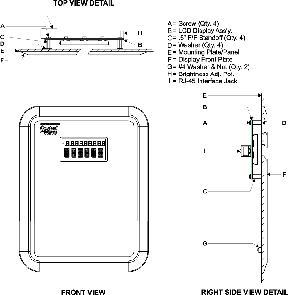
2-38 / Installation & Operation CI-ControlWave Express
Figure 2-28 - LCD Display (Only) Assembly Installation Drawing
2.4.5.2 Operation of the Dual-button Display/Keypad Assembly
The Display will have a timeout of 20 minutes. If there has been no keypad activity for this
time the display will “logout,” i.e., the display will be turned off and scrolling stopped until
a key press occurs. When a key press occurs after a timeout the display will return to the
opening screen.
If a shorter timeout of the display is needed for power savings, another timeout may be
implemented. The processor connected to the display will control the timeout. When the
timeout occurs the display will be blanked, but communications between the ControlWave
Express CPU and display processor will still occur. The display processor will ignore
posting the messages to the screen when in the low power mode. When a key is pressed the
display processor will return to displaying information to the display.
Click here to return to Table of Contents
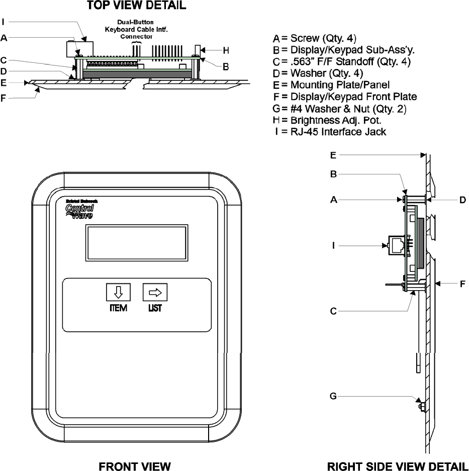
CI-ControlWave Express Installation & Operation / 2-39
Figure 2-29 - Dual-button Display/Keypad Assembly Installation Drawing
Displays are organized into screens as follows:
Opening Screen: User defined strings
List Selection Screen: List Name
List Number
<Blank Line>
<Blank Line>
The List Selection screen is entered from the main opening screen by pressing the right
arrow. Once here the operator can select which list is to be viewed. The operator can
traverse though different list numbers by pressing the down arrow key. When the list to be
scrolled is shown on the display, pressing the right arrow key will bring the operator to the
Display Element screen.
Click here to return to Table of Contents
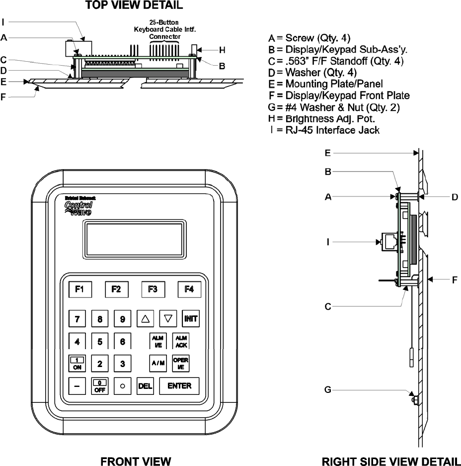
2-40 / Installation & Operation CI-ControlWave Express
Figure 2-30 - 25-Button Display/Keypad Assembly Installation Drawing
Display Element Screen: <Blank Line>
<Blank Line>
Variable Name
Variable Name
The Display Element screen is entered from the list selection screen by pressing the right
arrow. Once here the operator can view the variables in the list. Once entered the first
element of the list is displayed and then next element will be displayed after the scroll
timeout occurs. The scrolling will continue displaying the next element in the list and then
wrapping around to the beginning of the list. The down arrow key will toggle the display
through hold and scroll mode. Pressing the right arrow key will bring the operator to the
list selection screen.
Display/Keypad Assemblies are supported by Automatic Mode and Manual Mode.
Click here to return to Table of Contents

CI-ControlWave Express Installation & Operation / 2-41
Automatic Mode
In Automatic mode a set of screens (based on the application) are displayed. The
application programmer provides strings for the opening screen. From there the firmware is
responsible for displaying the screens and responding to key presses. Screens are fixed and
start off with an opening screen, which displays user information passed into the function
block. Users can view a list to select which list is to be scrolled. Once the list to be scrolled
has been selected, the user can scroll through the list by pressing the down arrow key. List
elements will be displayed automatically, scrolling at a predetermined rate (determined by
iiScrollTime). The user may pause on a variable by pressing the right arrow key. Pressing
the right arrow key again will cause the list to start scrolling again.
The essence of Automatic mode is that the user can supply inputs into the function that will
determine which list can be displayed, but cannot change the menu or display. The user is
allowed to select a list and to start/stop scrolling.
Manual Mode
In Manual Mode the programmer is responsible for creating each screen and displaying the
next desired screen, based on key inputs. The programmer has access to all lines of the
display and can provide any string that he/she desires to display. Special formats that must
be adhered to that allow the programmer to display what they want on the screen are
provided in the description of iaScrnSruct in the Display function block within ControlWave
Designer’s On-Line Help. It should be noted that currently, Manual Mode does not support
reading Keypad keypresses. Note: Manual Mode operation requires ControlWave
Firmware 4.50 or newer.
Click here to return to Table of Contents
BLANK PAGE
Click here to return to Table of Contents

CI-ControlWave Express Service / 3-1
Section 3
ControlWave Express SERVICE
3.1 SERVICE INTRODUCTION
This section provides general, diagnostic and test information for the ControlWave Express.
The service procedures described herein will require the following equipment:
1. PC with null modem interface cable & Bristol WINDIAG Software
2. Loop-back plugs/wires (for RS-232 and RS-485) (see Figures 3-9 & 3-10)
The following test equipment can be used to test the Power Supply/Sequencer Module:
1. DMM (Digital Multimeter): 5-1/2 digit resolution
2. Variable DC Supply: Variable to 30Vdc @ 2.5A (with vernier adjustment)
When ControlWave Express RTUs are serviced on site, it is recommended that any
associated processes be closed down or placed under manual control. This precaution will
prevent any processes from accidentally running out of control when tests are conducted.
Warning
Harmful electrical potentials may still be present at the field wiring terminals
even though the ControlWave Express power source may be turned off or
disconnected. Do not attempt to unplug termination connectors or perform any
wiring operations until all the associated supply sources are turned off and/or
disconnected.
Warning
Always turn off the any external supply sources used for externally powered
I/O circuits, before changing any printed circuit boards.
3.2 COMPONENT REMOVAL/REPLACEMENT PROCEDURES
This section provides information on accessing ControlWave Express components for
testing, as well as removal/replacement procedures.
3.2.1 Accessing Components For Testing
Testing and replacement of ControlWave Express components should only be performed by
technically qualified persons. Familiarity with the disassembly and test procedures
described in this manual are required before starting. Any damage to the ControlWave
Express resulting from improper handling or incorrect service procedures will not be
covered under the product warranty agreement. If these procedures cannot be performed
properly, the unit should be returned to the factory (with prior authorization) for evaluation
and repairs.
Click here to return to Table of Contents
3-2 / Service CI-ControlWave Express
3.2.2 Removal/Replacement of the CPU/System Controller Board & the
Process I/O Board
1. Loosen the two Thumb Screws and remove the Removable Card Edge Cover.
2. If the ControlWave Express is running, place any critical control processes under
manual control and shut down the unit by disconnecting power to the CPU/System
Controller Board Assembly at TB1 and, if applicable, TB2.
3. Disconnect all removable card edge connectors from the CPU/System Controller
Board and the Process I/O Board making sure they are identified so they can be
returned to their assigned connectors.
4. If present, disconnect the Keypad or Keypad/Display cable from connector J2 on the
CPU/System Controller Board.
5. Carefully slide the boards out of the Enclosure/Mounting Chassis.
6. If either the CPU/System Controller Board or Process I/O Board is to be replaced,
the two units must be separated from each. Use a pair of needle nose pliers to
squeeze the pair of tabs (associated with each of the six nylon mounting posts) while
gently pulling the CPU/System Controller Board away from the Process I/O Board.
Carefully unplug the boards from their interface connectors. The replacement boards
must be aligned with each other and pressed together such that the interface
connectors and mounting posts properly mate and then must be squeezed together
such that the mounting post tabs capture the CPU/System Controller Board.
7. To install these boards, power must be off. Align the boards (assembly) with the
Enclosure/Mounting Chassis guides (such that the Process I/O Board is adjacent to
the bottom of the unit and then slide the boards (assembly) into the unit.
8. Replace all cables removed in steps 2 through 4.
9. Replace the Removable Card Edge Cover and tighten the two Thumb Screws. Apply
power and test the unit.
3.3 TROUBLESHOOTING TIPS
3.3.1 CPU/System Controller Board Voltage Checks
One bulk power source or an internal battery (Primary Power System) can be connected to
the CPU/System Controller Board Assembly. Connector TB1 provides 2 input terminal
connections for bulk power (see Figure 3-3):
TB1-3 = (+VIN) (+5.4V to +16V for 6Vdc supply) (+11.4V to +16V for 12Vdc supply) (+21.8V
to +28V for 24Vdc supply)
TB1-4 = Chassis Ground - CHASSIS
Click here to return to Table of Contents
CI-ControlWave Express Service / 3-3
Bulk supply voltages can be checked at TB1 using a voltmeter or multimeter. CPU/System
Controller Board Assemblies are factory configured for use with a nominal 6Vdc or 12Vdc
bulk power supply. The maximum and minimum input power switch-points can be tested
with the use of a Variable dc Power Supply connected between TB1-3 (+) and TB1-4 (-). By
increasing the input voltage (starting at less than +4.3Vdc, 9.5Vdc or 19.2Vdc) for +6V,
+12V or +24V units respectively, you can determine the point at which the unit will turn
on, i.e., the point at which the LCD Display comes ON (Vt+). By decreasing the input
voltage (starting at +8Vdc, +16Vdc or +28Vdc), you can determine the point at which the
unit turns off, i.e., the point at which the LCD Display goes OFF (Vt-). If the value of the
Primary Power System (battery) or bulk power supply’s +6Vdc, +12Vdc or +24Vdc output
approaches the value of Vt+ or Vt- it should be replaced by a battery/power supply with the
correct +6Vdc, +12Vdc or +24Vdc output.
3.3.2 LED and LCD Checks
CPU/System Controller Boards for the ControlWave GFC, GFC Plus, Express, Express
Plus, and Corrector are equipped with two red LEDs that provide the following status
conditions when lit: WD (CR1 - Right) – Indicates Watchdog condition has been detected &
IDLE (CR1 - Left) - Indicates the CPU has free time at the end of its execution cycle.
Normally, the Idle LED should be ON most of the time (unless disabled). When the Idle
LED is OFF, it indicates that the CPU has no free time, and may be overloaded.
CPU/System Controller Boards for the ControlWave Express ONLY are also equipped with
a piggyback mounted LED Board. These LEDs provide the following status conditions when
lit:
PG (Red) - ON = Power Good
WD (Red) - ON = Watchdog Condition - OFF = Normal Operation
IDLE (Red) - ON = CPU has free time at the end of its execution cycle
TX1, TX2, TX3 (Red) - ON = transmit activity on COM1, COM2 & COM3 (respectively)
RX1, RX2, RX3 (Red) - ON = receive activity on COM1, COM2 & COM3 (respectively)
Six Status LEDs (Red) - provide run time status codes (see Table 3-1 and Figure 3-1)
Normally, the Idle LED should be ON most of the time (unless disabled). When the Idle
LED is OFF, it indicates that the CPU has no free time, and may be overloaded.
Ethernet Port Connector J1 on the CPU/System Controller Board contains two LEDs that
indicate transmit (yellow) and receive (green) activity when lit.
An optional LCD Display provides system status codes that are useful in troubleshooting
the unit (see Table 3-1).
Click here to return to Table of Contents
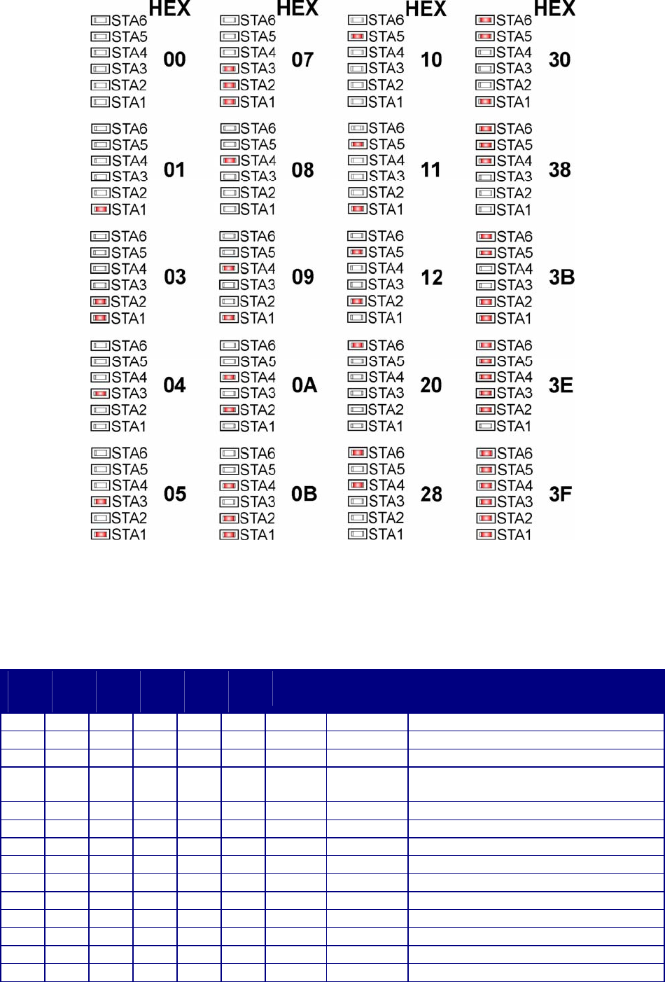
3-4 / Service CI-ControlWave Express
Figure 3-1 - CPU/System Controller LED Board – Status LED Hexadecimal Codes
(See Table 3-1 for Definitions)
Table 3-1 - System Status Codes on LCD Display
& LEDs on CPU/System Controller Board’s LED Display Board.
LED
6
STA6
LED
5
STA5
LED
4
STA4
LED
3
STA3
LED
2
STA2
LED
1
STA1
Status
In Hex
LCD
Disp.
Indication
Definition
0 0 0 0 0 0 00 Blank Application Running
0 0 0 0 0 1 01 DIAG Unit in Diagnostic Mode
0 0 0 0 1 1 03 R DIAG Unit Running Diagnostics
0 0 0 1 0 0 04 FWXSU
M
Flash XSUM Error
0 0 0 1 0 1 05 DEVERR Error Initializing Application Device
0 0 0 1 1 1 07 FLASH Flash Programming Error
0 0 1 0 0 0 08 FACT Using Factory Defaults *
0 0 1 0 0 1 09 BATT Battery Failure Detected *
0 0 1 0 1 0 0A STRTUP Currently Loading the Boot Project
0 0 1 0 1 1 0B INIT System Initialization in Progress
0 1 0 0 0 0 10 RECOV Waiting in Recovery Mode
0 1 0 0 1 0 12 RAMERR Error Testing SRAM
1 0 0 0 0 0 20 STOP Application Loaded
1 0 1 0 0 0 28 HALT Stopped at a Break Point
Click here to return to Table of Contents

CI-ControlWave Express Service / 3-5
1 1 0 0 0 0 30 NO APP No Application Loaded
1 1 1 0 0 0 38 BREAKP Running with Break Points
1 1 1 0 1 1 3B POWERD
Waiting for Power-down (after NMI)
1 1 1 1 1 0 3E UPDUMP
Waiting for Updump to be
Performed
1 1 1 1 1 1 3F NOTRUN Unit Crashed (Watchdog Disabled)
* = Flashed at startup
3.3.3 Wiring/Signal Checks
Check I/O Field Wires at the Card Edge Terminal Blocks and at the field device. Check
wiring for continuity, shorts & opens. Check I/O signals at their respective Terminal Blocks
(see Figures 3-1 through 3-4).
3.4 GENERAL SERVICE NOTES
Certain questions or situations frequently arise when servicing the ControlWave
ExpressPAC. Some items of interest are provided in Sections 3.4.1 through 3.4.4.
3.4.1 Extent of Field Repairs
Field repairs to a ControlWave Express are strictly limited to the replacement of complete
modules. Component replacement on a ControlWave Express Module constitutes tampering
and will violate the warranty. Defective ControlWave Express components (printed circuit
boards, LCD Displays, etc.) must be returned to the factory for authorized service.
Click here to return to Table of Contents
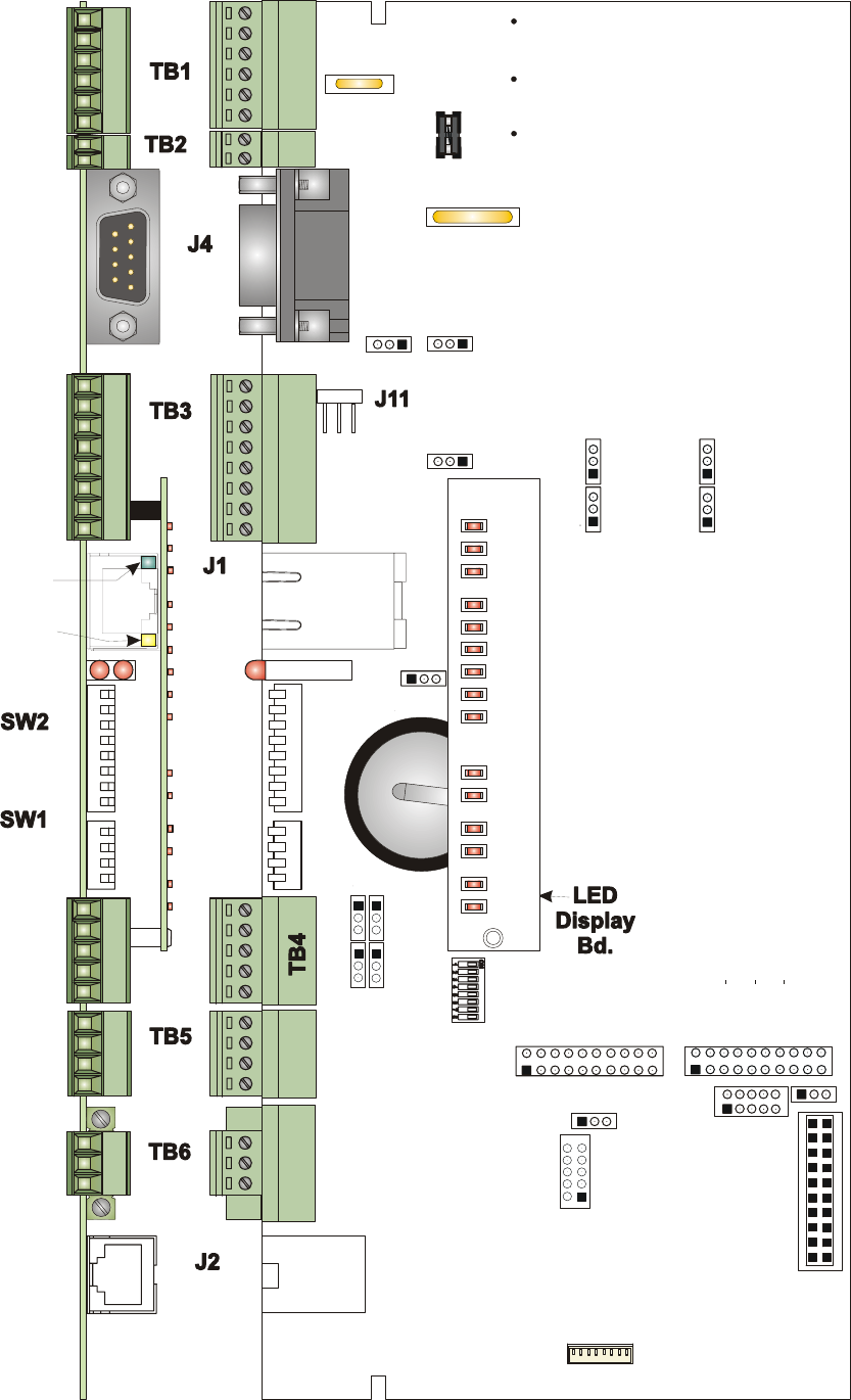
3-6 / Service CI-ControlWave Express
S1
1234
12345678
1
1
2
2
3
4
5
6
RJ-45
RJ-45
W3: 1-2 = Battery Enabled
2-3 = Battery Disabled
W2: 1-2 = COM2 CTS from Port
W5: 1-2 = 12/24V Power Supply
Shut-down Hysterisis
Shut-down Hysterisis
2-3 = 6V Power Supply
W6: 1-2 = 12V Power Supply
Shut-down
Shut-down
2-3 = 6/24V Power Supply
2-3 = COM2 CTS to RTS
W1: 1-2 = COM1 CTS from Port
2-3 = COM1 CTS to RTS
SW3 - COM3 Config.
RS-485 Receiver Biasing & Termination
2-Wire, 4-Wire Selction J5 - COM3
Piggy-back
Radio Intf.
J3 - I/OBUS
Intf. to
CPU Board
P1 WE
J7
MSP430
JTAG
Header
J9
PLD JTAG
Header
J8
Emulation
Header
J3
J5
W14
W16
W7
W1
3 2 1
W18
F3
W2
W3
W8
W6
W5
W15 W12
W13
Pulse
Input
LCD/
Keypad
Power
Power
GND
Sec. Battery Input
Power In +
Aux. Power Out +
Solar Pwr. In +
GND
GND
GND
P1 is only available on
Ultra Low Power CPU/-
System Controller Bds.
NOTE:
1
5
6
1
2
3
4
5
6
7
8
9
1
2
3
4
5
6
7
8
1
2
3
4
5
TXD-/TXD
GND
RXD+
RXD-/RXD
Input
Input
Output
Output TXD+
4
1
2
3
GND
PULSE 1
PULSE 2
Input
Input
Output PULSE
PWR
COM2
RS-232
10/100
Base-T
Ethernet
Port
COM1
RS-232
COM1
RS-232
Configuration
Options
Switch
Recovery
Mode &
COM./Status
LEDs
1
O
N
234
O
N
12345678
Receive
LED
Transmit
LED
TXD
GND
DCD
RXD
DTR
DSR
RTS
CTS
TXD
TXD
GND
GND
DCD
RXD
RXD
Input
Input
Output
Output
Output
Input
Input
Input
Input
Output
Output
Output
Input
Input
DTR
DSR
RTS
CTS
RTD
Input
1
2
3
RTD-
CAUTION:
Damage WILL occur to
the CPU if the Ethernet
network is connected
to connector J2!
RTD EXC
RTD+
COM3
RS-232
RS-485
PG
WD
STA6
STA5
STA4
STA3
STA2
STA1
TX1
RX1
TX3
RX3
TX2
RX2
IDLE
W12 - W16: 1-2 = COM3 RS-232
2-3 = COM3 RS-485
W7: 1-2 = 12/24V Power Fail
Trip Point Hysterisis
Trip Point Hysterisis
2-3 = 6V Power Fail
W8: 1-2 = 12V Power Fail
Trip Point
Trip Point
2-3 = 6/24V Power Fail
Trip Point
NOTE:
J7, J8, J9
Factory Use
W17
RJ-45
Solar Pwr. In and Aux. Power Out
are not available on units equipped
with an Ethernet Port.
Ultra Low Power & Low Power
CPU/System Controller Bds.
Don’t have an Ethernet Port.
NOTE:
Do Not Connect a 24V Solar Panel
to Connector TB1-1 & TB1-2!
Note: W17 is N/A on 24V Systems
Do Not Connect a 24V Solar
Panel to TB1-1 & TB1-2!
W17: 6/12V CPUs
1-2 = 6V S. P. Charging System
2-3 = 12V S. P. Charging System
W17: 12/24V CPUs
W18: COM1 connector
selection
1 to 2 = J4 active
2 to 3 = J11 active
1-2 = 12V S. P. Charging System
2-3 = N/A
NOTE:
J11 normally used
for CW GFC and CW
Express PAC only.
2 = Watchdog
1 = Idle
}
CR1
CR1 2
1
Figure 3-2 - CPU/System Controller Bd. Component Identification
Click here to return to Table of Contents

CI-ControlWave Express Service / 3-7
Figure 3-3 - Process I/O Board Component Identification Diagram
Click here to return to Table of Contents

3-8 / Service CI-ControlWave Express
Figure 3-4 - Process I/O Board Field I/O Wiring Diagram
Click here to return to Table of Contents
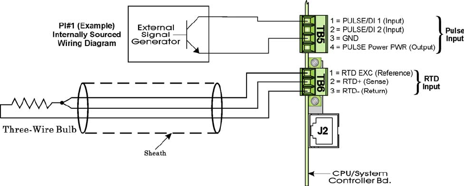
CI-ControlWave Express Service / 3-9
Figure 3-5 - CPU/System Controller Board Field I/O Wiring Diagram
3.4.2 Disconnecting RAM Battery
The ControlWave Express RTU Lithium RAM battery cannot be replaced while power is on.
Once the RAM battery has been replaced, the unit will still execute its FLASH-based
application (Boot Project) upon power-up, but all of the current process data will have been
lost. Upon power-up, the unit will act as though it had just been booted and it will revert
back to the initial values specified in its application. The battery may be disabled by placing
the CPU/System Controller Board’s Battery Backup Jumper (W3) onto Jumper Posts 2 and
3.
3.4.3 Maintaining Backup Files
It is essential to maintain a backup disk of each ControlWave project to guard against an
accidental loss of configuration data. Without a backup record, it will be necessary to
reconfigure the entire application; that can be a very time consuming procedure. Always
play it safe and keep backup copies of your applications. A copy of the application can be
loaded into ControlWave ExpressPAC FLASH memory and/or saved to a PC’s hard disk as
a compressed ZWT file.
3.5 WINDIAG DIAGNOSTICS
Bristol WINDIAG program provides menu-driven diagnostics that have been
designed to assist a technician or Process Engineer in troubleshooting the
various ControlWave Express circuits. For more detailed descriptions of
ControlWave Express Windows Diagnostics than those provided herein see
Document D4041A - Chapters 1 & 7C.
Bristol WINDIAG Software is a diagnostic tool used for testing ControlWave Express
electronics including, I/O circuitry, CPU memory, communications ports, etc., for proper
performance. The ControlWave Express must be communicating with a PC equipped with
the WINDIAG program. CPU/System Controller Board configuration switch SW2-8 must be
set to the OFF (Closed) position to enable diagnostics. Communication between the
ControlWave Express (with/without application loaded) and the PC can be made via a Local
or Network Port with the following restrictions:
Click here to return to Table of Contents
3-10 / Service CI-ControlWave Express
• CPU/System Controller Board Switch SW2-8 must be OFF to run the WINDIAG
program. Setting SW2-8 OFF will prevent the ‘Boot Project’ from running and will place
the unit into diagnostic mode.
• Any ControlWave Express communication port can be connected to the PC provided
their port speeds and configuration match, e.g., baud rate, parity, stop bits, protocol, etc.
This can be accomplished via user-defined Soft Switches.
• Setting CPU/System Controller Board Switch SW2-3 OFF will force ports COM2 and
COM3 to 9600 baud, 8-bits, no parity, 1 stop bit, BSAP/ControlWave Designer protocol
operation.
• Communication port COM1 is only forced to 9600 bps operation when CPU/System
Controller Board Switches SW2-3 and SW2-8 have both been set OFF. COM1 can also
be set to 9600 bps operation via user defined Soft Switches.
• Setting CPU/System Controller Board Switches SW2-3 and SW2-8 OFF prevents the
‘Boot Project’ from running, places the unit into diagnostic mode and forces
communication ports COM1, COM2 and COM3 to operate at 9600 baud.
COM1: From the factory, RS-232 Communications Port COM1 (9-pin male D-type connector
J4, or 3-pin male connector J11) on the CPU/System Controller Board defaults to
115.2 kbd (RS-232) using the BSAP Protocol. Note: Port COM1 will be configured for
RS-232 operation (at 9600 baud) by setting CPU/System Controller Board
Switches SW2-3 and SW2-8 OFF. This will prevent the boot project from running
and places the unit into diagnostic mode. CPU/System Controller Board Switch
SW2-8 must be set OFF to run the WINDIAG program. Connection to a PC requires
the use of an RS-232 “Null Modem” cable (see Figure 2-5A).
COM2: From the factory, RS-2325 Communications Port COM2 (8-position Terminal Block
TB3) on the CPU/System Controller Board defaults to 9600 baud, 8-bits, no parity,
1 stop bit, BSAP/ControlWave Designer protocol operation (RS-232).
COM3: RS-232/RS-485 Communications Port COM3 (5-position Terminal Block TB4) on
the CPU/System Controller Board defaults to 9600 baud, 8-bits, no parity, 1 stop
bit, BSAP/ControlWave Designer protocol operation. In lieu of the use of an RS-232
Port, an RS-485 cable (see Tables 2-3B & 2-4) can be connected between COM3
and a PC’s RS-485 Port.
To use the WINDIAG program place any critical processes under manual control.
WINDIAG cannot be run while the ControlWave Express application is running. Set the
CPU/System Controller Board Switch SW2-8 to the OFF position. Perform steps 1 through 6
below.
1. Start the OpenBSI NetView Program. A screen similar to Figure 3-6 will appear.
2. To start WINDIAG program, click on Start Æ Programs Æ OpenBSI Tools Æ
Common Tools Æ Diagnostics.
3. Once WINDIAG has started, the Main Diagnostics screen of Figure 3-7 will appear.
Click here to return to Table of Contents

CI-ControlWave Express Service / 3-11
Figure 3-6 – NetView - Example with Multiple Networks
Figure 3-7 - WINDIAG Main Diagnostics Screen
Click here to return to Table of Contents
3-12 / Service CI-ControlWave Express
4. Select the module to be tested. Enter any prompted parameters (slot #, etc.). WINDIAG
will perform the diagnostics and display pass/fail results.
5. After all diagnostic testing has been performed, exit WINDIAG program and then exit
the NetView.
When you close Netview, you will be prompted as to whether or not you want to close
OpenBSI; select Yes.
6. Set ControlWave Express CPU/System Controller Board Switch SW2-8 to the ON
(Open) position. The ControlWave Express should resume normal operation.
3.5.1 Diagnostics Using WINDIAG
ControlWave Express electronics can be tested using the WINDIAG program. From
WINDIAG’s Main Diagnostics Menu (see Figure 3-8) the following diagnostic tests can be
performed:
CPU & Peripherals Diagnostic: Checks the CPU/System Controller Board [except for
RAM & PROM (FLASH)].
PROM/RAM Diagnostic: Checks the CPU/System Controller Board’s RAM and
PROM (FLASH) hardware.
Communications Diagnostic: Checks Comm. Ports 1, 2 and 3 - The External loop-back
tests require the use of a loop-back plug.
Analog Output Diagnostic: Checks AOs on the Process I/O Board.
Analog Input Diagnostic: Checks AIs on the Process I/O Board.
Discrete I/O Diagnostic: Checks DIs or DOs on the Process I/O Board.
High Speed Counter Diagnostic: Checks HSCs on the Process I/O Board & Pulse Counter
Inputs on the CPU/System Controller Board.
Keyboard & Display Diagnostics Checks Keyboard/Keypad & Display hardware
3.5.1.1 Communications Diagnostic Port Loop-back Test
WINDIAG’s Communications Diagnostic Menu (see Figure 3-10) provides for selection of
the communication port to be tested. Depending on the type of network (RS-232 or RS-485)
and the port in question, a special loop-back plug is required as follows:
Port 1 - RS-232 use a 9-pin female D-type loop-back plug (see Fig. 3-8).
Port 2 - RS-232 use loop-back wires (see Figure 3-8).
Port 3 - RS-232 use loop-back wires (see Figure 3-9)
Port 3 - RS-485 use loop-back wires or CPU Switch SW3 (see Figure 3-9).
This group of tests verifies the correct operation of the Communication Interface. COM1,
COM2 and COM3 can be tested with this diagnostic. The ControlWave Express
communication port that is connected to the PC (local or network and used for running
these tests) cannot be tested until diagnostics has been established via one of the other
ports, i.e., to test all ControlWave Express communication ports (via WINDIAG),
communications with the PC will have to be established twice (each time via a different
port). It should be noted that the ControlWave Express communication port that is
connected to the PC (RS-232, RS-485 or Ethernet) must be good for WINDIAG to run the
Communications Diagnostics
Click here to return to Table of Contents
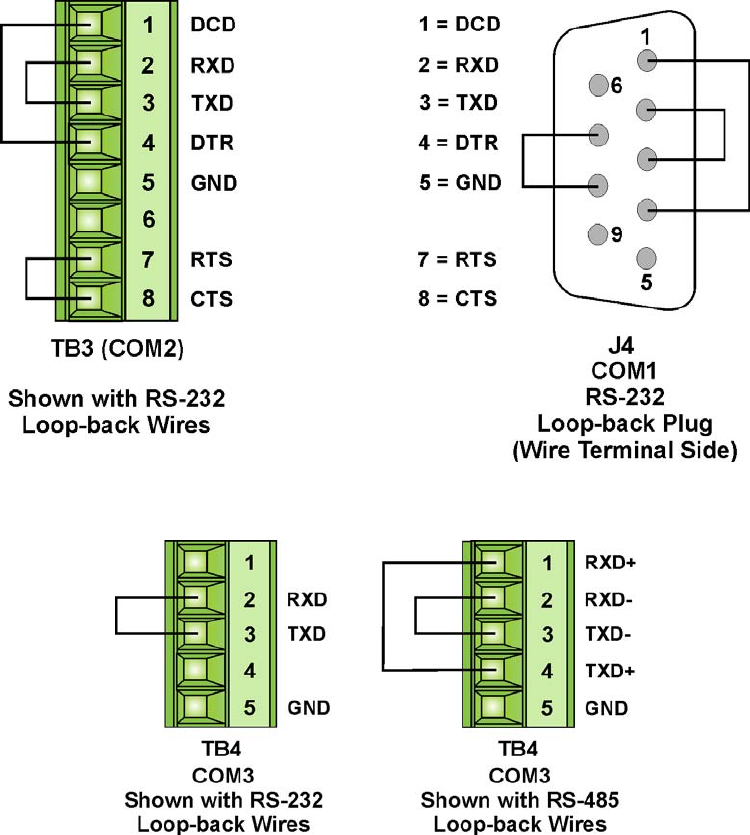
CI-ControlWave Express Service / 3-13
Figure 3-8 - COM1 & COM2 RS-232 Loop-back Plug/Wires
Figure 3-9 - COM3 RS-232 & RS-485 Loop-back Wires
Note: RS-485 Loopback can be achieved via CPU Switches SW3-1 & SW3-2 set ON
3.5.1.2 Serial Comm. Port External Loop-back Test Procedure
Connect an external loop-back plug or loop-back wires to the Communication Port to be
tested (see Figures 3-8 and 3-9).
1. Type "1," "2," "3," or "4" for the port to test.
2. Set baud rate to test to 115200 baud or ALL ASYNC and the number of passes to 5.
3. Click on RUN button next to External loop-back.
! Test responses:
a) Success - All sections of test passed
b) Failure - TXD RXD Failure
- CTS RTS Failure
! Execution time < 5 sec.
Click here to return to Table of Contents
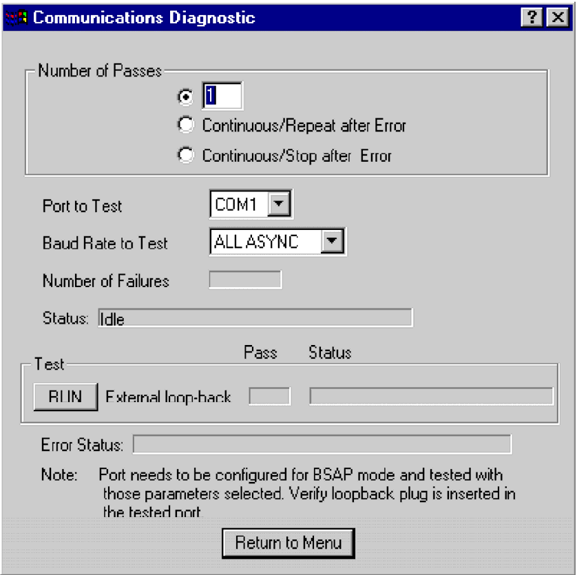
3-14 / Service CI-ControlWave Express
Figure 3-10 - WINDIAG’s Communications Diagnostic Menu
3.6 CORE UPDUMP
In some cases a copy of the contents of SRAM and SDRAM can be uploaded to a PC for
evaluation by Emerson Remote Automation Solutions division engineers. This upload is
referred to as a ‘Core Updump.’ A Core Updump may be required if the ControlWave
Express repeatedly enters a ‘Watchdog State’ thus ill-effecting system operation. A
Watchdog State is entered when the system crashes, i.e., a CPU timeout occurs due to
improper software operation, a firmware glitch, etc. In some cases the Watchdog State may
reoccur but may not be logically reproduced.
‘Crash Blocks’ (a function of firmware provided for watchdog troubleshooting) are stored in
CPU RAM. The user can view and save the ‘Crash Blocks’ by viewing the Crash Block
Statistic Web Page (see the Web_BSI Manual - D5087). Crash Block files should be
forwarded to Emerson support personnel for evaluation.
Follow the five steps below to perform a Core Updump.
Click here to return to Table of Contents
CI-ControlWave Express Service / 3-15
1. Set CPU/System Controller Board Switch SW2-1 OFF (Disable Watchdog Timer). If
Switch SW2-4 is ON, set it to OFF (Enable Core Updump). Note: The factory default
setting for SW2-4 is OFF.
2. Wait for the error condition (typically 3F on CPU/System Controller Board Status LEDs
or NOTRUN on optional LCD Display).
3. Connect ControlWave Express Comm. Port 1 to a PC using a half-duplex Null Modem
Cable (see Figures 2-5A).
4. Set CPU/System Controller Board Switch (SW1- Recovery) so that SW1-1 and SW1-2
are both in either the ON position or the OFF position.
5. Start the PC’s HyperTerminal Program (at 115.2kbaud) and generate a file using the
1KX-Modem protocol. Save the resulting Core Updump in a file to be forwarded for
evaluation.
When the Core Updump has been completed, set the CPU/System Controller Board’s
Recovery Switch as follows: SW1-1 is in the OFF position & SW1-2 is in the ON position.
3.7 CALIBRATION CHECKS
Calibration of the RTD is performed using OpenBSI’s TechView program (see document #
D5131 - TechView User’s Guide).
Click here to return to Table of Contents
BLANK PAGE
Click here to return to Table of Contents

CI-ControlWave Express Specifications / 4-1
Section 4
ControlWave Express SPECIFICATIONS
4.1 CPU, MEMORY & PROGRAM INTERFACE
Processor: Sharp’s LH7A400 32-bit System-on-Chip with 32-bit
ARM9TDMI RISC Core
Memory: 8 Mbytes of simultaneous read/write FLASH
2 Mbyte of on-board SRAM
512 Kbytes FLASH Boot/Downloader
Real Time Clock: A Semtech SH3000 support IC provides a full BCD clock
calendar with programmable periodic/wakeup interrupt and
a programmable clock generator with adjustable spectrum
spreading.
Connectors: (see Table 4-1 and referenced Tables)
4.2 CPU/SYSTEM CONTROLLER BOARD
4.2.1 Input Power Specs.
Note: Voltages are dc unless otherwise specified.
Operating Range: +5.4V to +16.0V (+6V nominal Input Supply)
+11.4V to +16.0V (+12V nominal Input Supply)
+21.8V to +28.0V (+24V nominal Input Supply)
Output Voltages: +3.3Vdc ±1%
Output Current: 1A Max. @ 3.3Vdc
Output Ripple P/P: +3.3V Output: 10mV
Fusing: 3.5A Slow Blow 5x20mm Fuse
Electrical Isolation: None
Surge Suppression: 16V Transorb to DGND and Chassis
Meets ANSI/IEEE C37.90-1978
Terminations: Pluggable, maximum wire size is 16 gauge
Shutdown: +6V System
Below +4.3Vdc
+12V System
Below +9.5Vdc
+24V System
Below +19.2Vdc
Click here to return to Table of Contents

4-2 / Specifications CI-ControlWave Express
4.2.2 Power Supply Sequencer Specs.
Signals Monitored: Input Power
Sequencer Switchpoints: +3.3V Max. ON Switchpoint = +3.15V
+3.3V Min. OFF Switchpoint = +3.00V
+1.8V Max. ON Switchpoint = +1.72V
+1.8V Min. OFF Switchpoint = +1.64V
Sequencer Output Signals: PFDLYCLK Timing on power down 2msec after POWER-
FAIL
VIN100M timing on power up 1.8 second delay for Good
Power
POWERGOOD incoming power, 3.3V & 1.8V in Spec.
4.2.3 CPU/System Controller Board Connectors
Table 4-1 - CPU/System Controller Board Connector Summary
Ref. # Pins Function Notes
J1 8-Pin 10/100Base-T Ethernet Port (RJ-45) see Table 2-6
J2 10-Pin 25-Button Display/Keypad Intf. RJ-45 Jack (or Display Only)
J3 20-Pin I/O Bus Interface Header Intf. to CPU/System Controller Bd.
J4 9-Pin D-Type - Male (COM1 - RS-232) see Figure 4-1 & Table 4-2A
J5 20-Pin Radio Daughter Board
J7 10-Pin MSP430 JTAG Header Factory Use Only
J8 20-Pin Emulation Header Factory Use Only
J9 10-Pin PLD JTAG Header Factory Use Only
J11 3-Pin Alternate COM1 (RS-232) For GFC models
P1 8-Pin MVT Interface Connector Near Bottom of Board
TB1 6-Pin Term. Block - Power see Figure 4-4
TB2 2-Pin Term Block – Alternate Power see Figure 4-4
TB3 8-pin Term. Block (COM2 - RS-232) see Table 4-2 & Fig. 4-2
TB4 5-pin Term. Block (COM3 - RS-232/RS-485) see Table 4-3 & Fig. 4-3
TB5 4-Pin Term. Block - Pulser 1 & 2 Interface see Figure 4-5
TB6 3-Pin Term. Block - RTD Interface see Figure 4-6
4.2.3.1 Communication Ports
Connector/Port: CPU/System Controller Board
J1 - 8-Pin RJ-45 Jack (10/100Base-T Ethernet Port)
J4 - 9-Pin D-Type - COM1 (RS-232)
TB3 - 8-Pos. Term. Block - COM2 (RS-232)
TB4 - 5-Pos. Term. Block - COM3 (RS-485/485)
Baud Rate: 300 to 115Kbps for RS-232 or RS-485
Up to 56Kbps for Modem
10/100 Mbps for Ethernet Port
Click here to return to Table of Contents
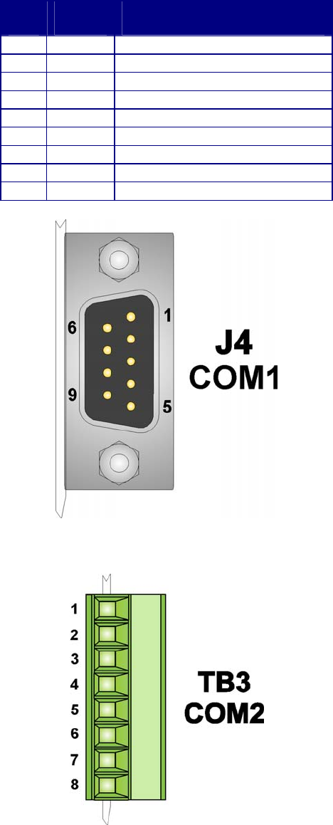
CI-ControlWave Express Specifications / 4-3
Table 4-2 - RS-232 Ports (COM1 & 2)
Connector Pin Assignments (J4 - COM1 & TB3 COM2)
Located on CPU/System Controller Bd.
Pin
#
Signal
RS-232
Description:
RS-232 Signals
1 DCD Data Carrier Detect Input
2 RXD Receive Data Input
3 TXD Transmit Data Output
4 DTR Data Terminal Ready Output
5 GND Signal/Power Ground
6 DSR Data Set Ready Input
7 RTS Request To Send Output
8 CTS Clear To Send Input
9 N/A
Figure 4-1 - DB9 9-Pin Connectors J4 (COM1) on CPU/System Controller Bd.
Figure 4-2 - 8-Position Term. Block TB3 (COM2) on CPU/System Controller Board
Click here to return to Table of Contents
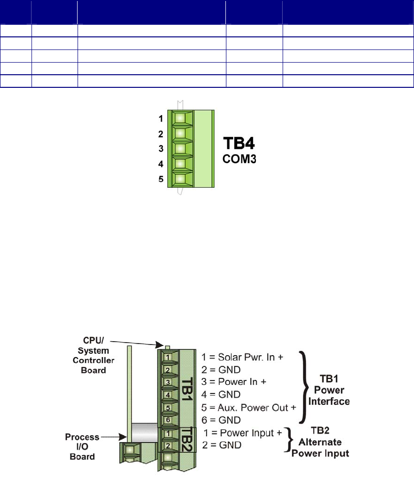
4-4 / Specifications CI-ControlWave Express
Table 4-3 - RS-232/485 Port (COM3) Connector TB4 Pin Assignments
Pin
#
Signal
RS-232
Description:
RS-232 Signals
Signal
RS-485
Description:
RS-485 Signals
1 - - RXD+ Receive Data + Input
2 RXD Receive Data Input- RXD− Receive Data − Input
3 TXD Transmit Data Output TXD− Transmit Data − Output
4 - - TXD+ Transmit Data + Output
5 GND Signal/Power Ground GND Ground
Figure 4-3 - 5-Position Term. Block (COM3) TB4 on CPU/System Controller Board
4.2.3.2 Power Interface & Field Input Connections
Power Interface: see Figure 4-4 (see Sections 4.2.1 & 4.2.2)
Pulse Input Interface: see Figure 4-5
RTD Input Interface: see Figure 4-6
Figure 4-4 - Terminal Blocks TB1 and TB2
Pulse/Digital Inputs
No of Inputs: 2
Input Configuration: 3.3V Input Source Voltage
200uA Input Source Current
Driven Open Collector
ON State: below 1.46V
OFF State: above 1.90V
Click here to return to Table of Contents
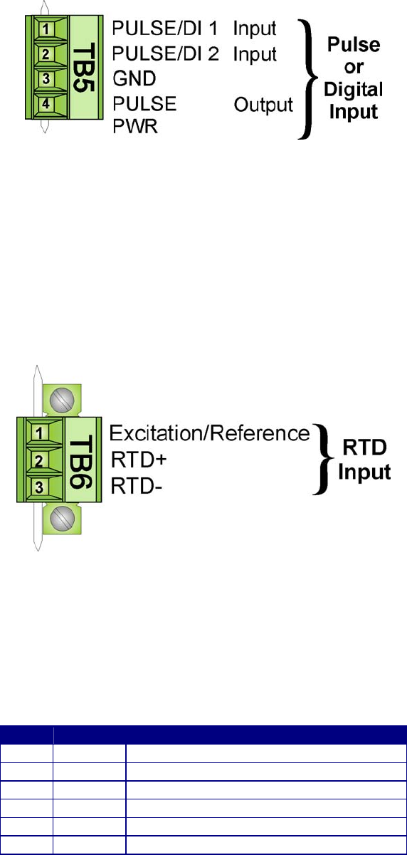
CI-ControlWave Express Specifications / 4-5
Max. Input Frequency: 10 kHz
Signal conditioning: 20 microsecond Filtering.
Figure 4-5 - 4-Position Pulse Input Interface Terminal Block TB5
RTD Input Note: Only Available on 14MHz CPUs
RTD Type: 100-ohm platinum bulb (using the DIN 43760 curve).
Configuration: The common three-wire configuration is accommodated. In
this configuration, the return lead connects to the RTD-
terminal while the two junction leads (Sense and
Excitation) connect to the RTD+ terminals.
Figure 4-6 - 3-Position RTD Input Interface Terminal Block TB6
4.3 PROCESS I/O BOARD SPECIFICATIONS
4.3.1 Process I/O Board Connectors (see Figure 4-7 & Table 4-4)
Table 4-4 - Process & I/O Board User Connector Summary
Ref. # Pins Function
P1 20-pin CPU/System Controller Intf. Connector
TB2 6-pin Term. Block - DI Interface
TB3 8-pin Term. Block - DO & DI/O Interface
TB4 8-pin Term. Block - HSC Interface
TB6 9-pin Term. Block - AI Interface
TB7 4-pin Term. Block - AO Interface
Click here to return to Table of Contents
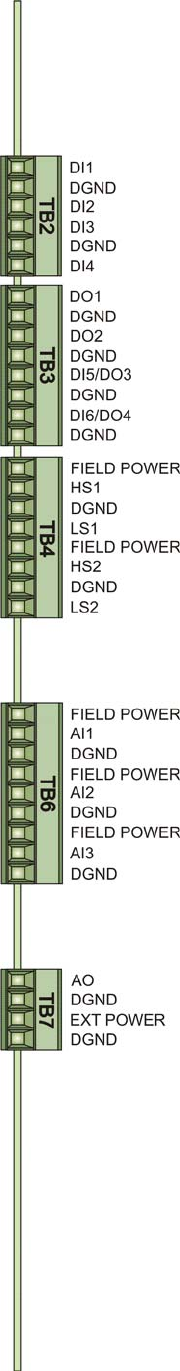
4-6 / Specifications CI-ControlWave Express
Figure 4-7 - Process I/O Board Edge View (Connector Identification)
Click here to return to Table of Contents

CI-ControlWave Express Specifications / 4-7
4.3.2 Non-isolated Digital Input/Output Circuitry Specs.
Non-isolated Digital Inputs
Number of Inputs: 4 Fixed, 2 Selectable DI - Internally Sourced (Dry Contact)
operation
Input Filtering: 15 milliseconds
Input Current: Switch Selectable (SW1-3)
DI1 through DI4 (SW1-3: ON = 2mA, OFF = 60uA)
DI5 & DI6 (SW1-3: ON = 2.2mA, OFF = 200uA)
Bus Access: SPI
ON State Voltage: below 1.3V
OFF State Voltage: above 1.6V
Electrical Isolation: None
Surge Suppression: 30V Transorb between signal and ground
Meets ANSI/IEEE C37.90-1978
Status Indication: None
Non-isolated Digital Outputs
Number of Outputs: 2 Fixed, 2 Selectable DO
Output Configuration: Open Drain (Externally Powered)
Maximum Load Current: 400mA each 30Vdc
Electrical Isolation: None
Surge Suppression: 30V Transorb between signal and ground
Meets ANSI/IEEE C37.90-1978
General DI/DO Circuitry Specs.
Terminations: Pluggable, max wire size is 16 AWG
4.3.3 Non-isolated Analog Input/Output Circuitry Specs.
Non-isolated Analog Inputs
Number of Inputs: 3 Single Ended Inputs (1-5V or 4-20mA) individually
jumper configurable
Input Type: (Externally Powered) Voltage Input: 1-5 Vdc
(Externally Powered) Current Loop: 4-20mA
Click here to return to Table of Contents

4-8 / Specifications CI-ControlWave Express
Input Impedance: 1 Meg ohm for 1-5V inputs
250 ohm for 4-20mA inputs
Settling Time: 600 msec to within 0.1% of input signal
Conversion Time: 20 usec
Non-isolated Analog Outputs
Number of Outputs: 1 AO (1-5V or 4-20mA) individually jumper configurable
4-20mA Output
Compliance: 250 ohm load with 11V External Power Source
650 ohm load with 24V External Power Source
1-5V Output: 5mA maximum output current into external load with
external voltage range of 11 to 30 Vdc
General AI/AO Circuitry Specs.
Accuracy: Analog Input
0.1% of Span @ +25ºC (+77ºF)
0.2% of Span @ -40ºC to +70ºC (-40ºF to 158ºF)
Analog Output
Current Output:
0.1% of Span @ +25ºC (+77ºF)
0.2% of Span @ -20ºC to +70ºC (-4ºF to 158ºF)
0.3% of Span @ -40ºC to +70ºC (-40ºF to 158ºF)
Voltage Output (Iloadmax = 5mA):
(see Note1 & Note2)
0.1% of Span + (2.5 ohms x Iload)/4.4V x 100@ +25ºC (+77ºF)
0.2% of Span + (2.5 ohms x Iload)/4.4V x 100 @ -20ºC to +70ºC
(-4ºF to +158ºF)
0.3% of Span + (2.5 ohms x Iload)/4.4V x 100 @ -40ºC to +70ºC
(-40ºF to 158ºF)
where X = [(2.5 ohms x Iload)/4.4V x 100]
Note1: Does not include error due to inductors
Note2: 2.5 ohm uncompensated series resistance with
Inductors
Terminations: Pluggable - Max. wire size is 16 AWG
Data Transfer: SPI
4.3.4 Non-isolated High Speed Counter Input Circuitry Specs.
Number of Inputs: 2 HSC Inputs
Input Configuration: Internally Sourced Dry Contact
Click here to return to Table of Contents

CI-ControlWave Express Specifications / 4-9
Input Frequency: Individually switch-selectable high (10kHz Max), or low
(300 Hz). SW1-1 (HSC1), SW1-2 (HSC2).
Input filtering: 20 microseconds on high speed (HS) and 1 millisecond on
low speed (LS).
Signal Conditioning: Bandwidth limiting
ON State Voltage: below 1.46V
OFF State Voltage: above 1.90V
Bus Access: SPI
Electrical isolation: None
Surge Suppression: 30V Transorb between signal and ground
Meets ANSI/IEEE C37.90-1978
Terminations: Pluggable, max wire size is 16 AWG
Status Indication: None
Power Consumption: Additional Current per Input
200uA per HS or LS Input (ON State)
4.4 ENVIRONMENTAL SPECIFICATIONS
Temperature: Operating: -40 to +158 °F (-40 to +70 °C)
Storage: -40 to +158 °F (-40 to +70 °C)
Relative Humidity: 0-95% Non-condensing
Vibration: 1g for 10 - 150 Hz
.5g for 150 - 2000 Hz
RFI Susceptibility: In conformity with the following standards:
IEC 1000-4-3 (Level 2): 3V/meter - 80MHz to 1000MHz
4.5 DIMENSIONS
NEMA 3R Enclosure RTU (see Figure 4-8)
Click here to return to Table of Contents
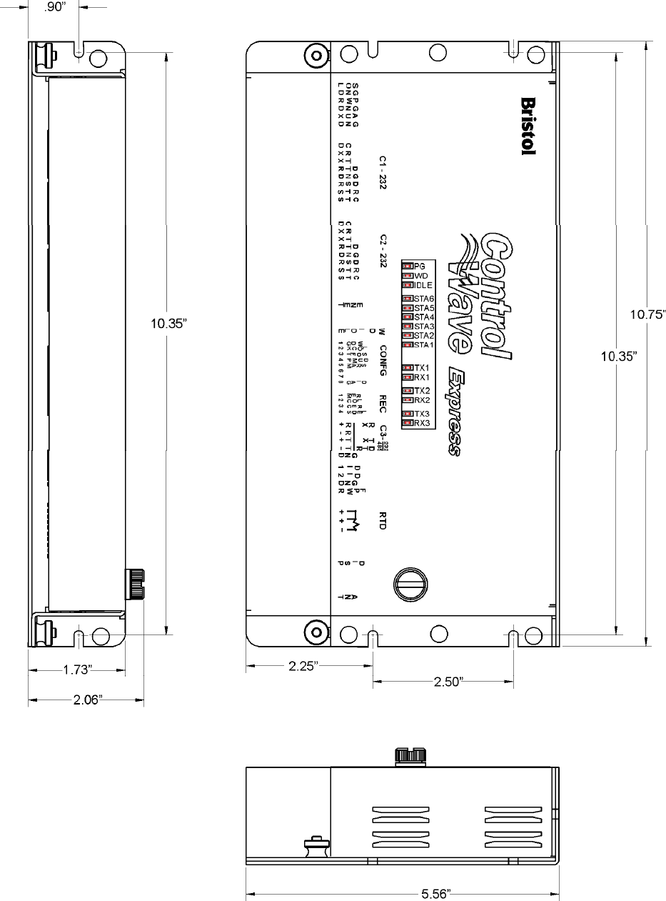
4-10 / Specifications CI-ControlWave Express
Figure 4-8 - ControlWave Express Dimensions
Click here to return to Table of Contents

ControlWave Express
Special Instructions for Class I, Division 2 Hazardous Locations
04/24/2006 Appendix A, Document CI-ControlWave Express Page 1 of 2
1. Bristol’s ControlWave Express RTU is listed by Underwriters Laboratories (UL) as nonincendive and
(when installed in a NEMA 1 or better enclosure) is suitable for use in Class I, Division 2, Group C and D
hazardous locations or nonhazardous locations only. Read this document carefully before installing a
nonincendive ControlWave Express RTU. Refer to the ControlWave Express RTU User's Manual for
general information. In the event of a conflict between the ControlWave Express RTU User's Manual
and this document, always follow the instructions in this document.
2. The ControlWave Express RTU includes both nonincendive and unrated field circuits. Unless a circuit
is specifically identified in this document as nonincendive, the circuit is unrated. Unrated circuits must
be wired using Div. 2 wiring methods as specified in article 501-4(b) of the National Electrical Code
(NEC), NFPA 70 for installations in the United States, or as specified in Section 18-152 of the Canadian
Electrical Code for installation in Canada.
3. The power system (solar panel and battery) are not supplied by Bristol Inc. and are therefore unrated
(see paragraph 2). Connection to the solar panel is approved as a nonincendive circuit so that Division 2
wiring methods are not required. The nominal panel voltage must match the nominal battery voltage (6V
or 12V).
4. WARNING: EXPLOSION HAZARD - Do Not disconnect Solar Power from the Battery or any
other power connections within the ControlWave Express Enclosure or any power
connections to optional items such as radio/modem, or cabling to the Display/Keypad unless
the area is known to be nonhazardous.
5. WARNING: EXPLOSION HAZARD - Substitution of major components may impair suitability
for use in Class I, Division 2 environments.
6. WARNING: EXPLOSION HAZARD - The area must be known to be nonhazardous before
servicing/replacing the unit and before installing or removing I/O wiring.
7. WARNING: EXPLOSION HAZARD - Do Not disconnect equipment unless power has been
disconnected and the area is known to be nonhazardous.
8. An optional RTD may be supplied with the ControlWave Express. Connection to the RTD is approved
as a nonincendive circuit, so that Division 2 wiring methods are not required.
9. Signal connectors available for customer wiring are listed in Table A1. Network Com-
munication Port and I/O wiring connections are unrated and must be wired using Div. 2 wiring
methods. No temporary connections may be made to the Local Port (COM1 -J4 on CPU/System
Controller Board) unless the user ensures that the area is known to be nonhazardous. Field Service
connections to this port are typically temporary, and must be short in duration to ensure that flammable
concentrations do not accumulate while it is in use.
Table A1 -Module/Board Connector Customer Wiring Connectors
Module/Item Connector Wiring Notes
CPU/System Controller
Board
TB1: 6-pin Term. Block Solar Power: User Wired - *
Primary Power: User Wired - *
Auxiliary Output: User Wired - *
CPU/System Controller
Board
TB3: COM2, 8-pin Term Block
RS-232
Remote Comm. Port: For Radio or external
Network Comm. Refer to Model Spec. and ¶ 9
of this document. When used for Network
Comm., use Div. 2 wiring methods.
CPU/System Controller
Board
TB4: COM3, 5-pin Term Block
RS-232/RS-485
RS-232/485 Comm. Port: For external Net-
work Comm. Refer to Model Spec. and ¶ 9 of
this document.
CPU/System Cntrl. Bd. TB5: 4-pin Term. Block
Pulse Input Interface
Pulse Input Field Wiring: Field I/O wiring
connector is unrated, use Div. 2 wiring
methods. *
CPU/System Cntrl. Bd. TB6: 3-pin Term. Block
RTD Interface
Field Wired: Refer to ¶ 8 of this document. *
CPU/System Controller
Board
J1: 8-pin RJ-45 Jack
10/100Base-T Ethernet Port
10/100Base-T Ethernet Port Jack
For external connection to an Ethernet Hub.
Refer to Model Spec. and ¶ 9 of this document.
CPU/System Controller
Board
J2: 8-pin RJ-45 Female
Connector – Display or
Display/Keypad Intf.
User Connected using Factory Wired Cable - *
CPU/System Controller
Board
J4: COM1, 9-pin Male D-sub
RS-232
RS-232 Comm. Port Connectors: For external
Network Comm. Refer to Model Spec. and ¶ 9
of this document.
Click here to return to Table of Contents

ControlWave Express
Special Instructions for Class I, Division 2 Hazardous Locations
04/24/2006 Appendix A, Document CI-ControlWave Express Page 2 of 2
Table A1 -Module/Board Connector Customer Wiring Connectors (Continued)
Module/Item Connector Wiring Notes
Process I/O Board TB2: 6-pin Term. Block
DI Interface
Discrete Input Field Wiring: Field I/O wiring
connector is unrated, use Div. 2 wiring
methods. *
Process I/O Board TB3: 8-pin Term. Block
DO/DI Interface
Discrete Output/Input Field Wiring: Field I/O
wiring connector is unrated, use Div. 2 wiring
methods. *
Process I/O Board TB4: 8-pin Term. Block
HSC Interface
High Speed Counter Field Wiring: Field Input
wiring connector is unrated, use Div. 2 wiring
methods. *
Process I/O Board TB6: 9-pin Term. Block
AI Interface
Analog Input Field Wiring: Field Input wiring
connector is unrated, use Div. 2 wiring
methods. *
Process I/O Board TB7: 4-pin Term. Block
AO Interface
Analog Output Field Wiring: Field Output
wiring connector is unrated, use Div. 2 wiring
methods. *
Note: * = These wires should only be installed/removed when the item (PCB) in question is
installed/removed or when checking wiring continuity. The area must be known to be
nonhazardous before servicing/replacing the unit and before installing or removing PCBs,
Connectors or individual I/O or Power wires. Refer to ¶ 5, 6 & 7 of this document. All input
power and I/O wiring must be performed in accordance with Class I, Division 2 wiring
methods as defined in Article 501-4 (b) of the National Electrical Code, NFPA 70, for
installations within the United States, or as specified in Section 18-152 of the Canadian
Electrical Code for installation in Canada.
Click here to return to Table of Contents
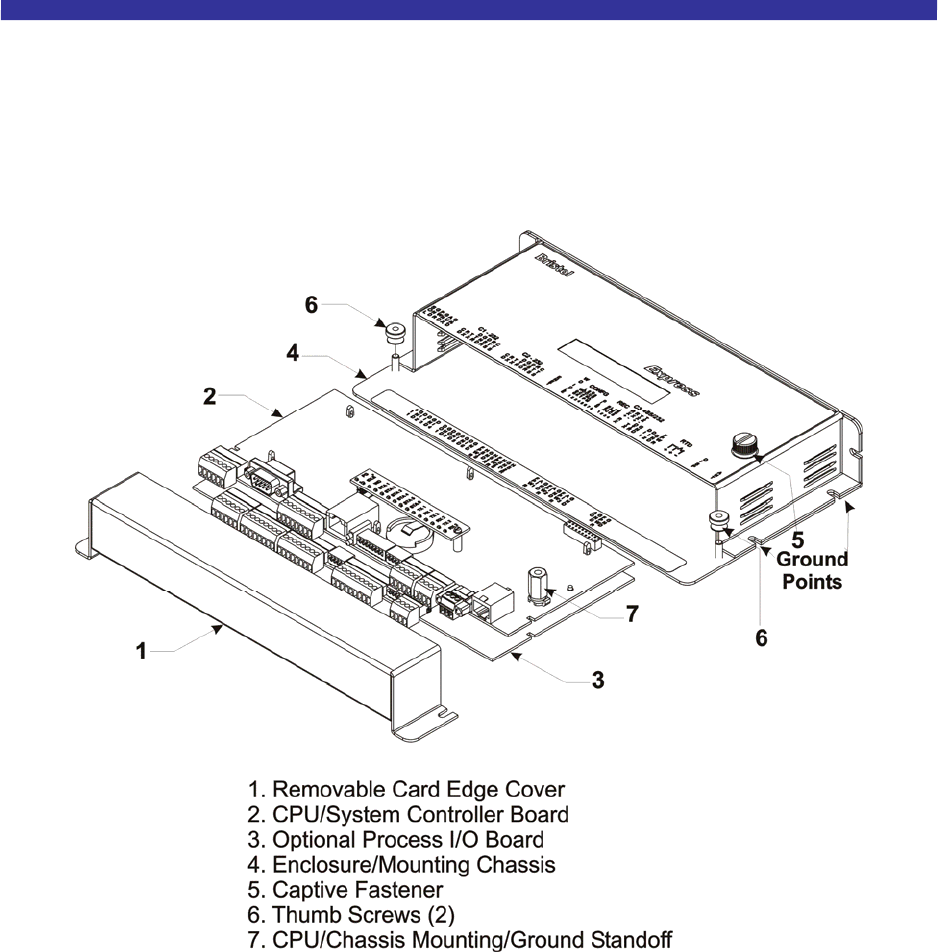
CI-ControlWave Express Appendix C - Hardware Installation Guide / C-1
Appendix C
HARDWARE INSTALLATION GUIDE
Hardware Configuration
There are seven (7) main steps required to configure a ControlWave Express. This appendix
provides an overview of these steps with an emphasis on the installation and configuration
of the hardware. This appendix is intended for users who have already installed at least one
ControlWave Express.
Figure C-1 - ControlWave Express - Component Identification Diagram
Step 1. Hardware Configuration
This involves unpacking the ControlWave Express hardware, mounting the enclosure,
wiring I/O terminations, connecting any permanent communication cables, making proper
ground connections, connecting a communications cable to a PC workstation, setting
switches and setting jumpers. To install and configure the ControlWave Express, follow the
steps below:
1. Remove the unit from its carton and install it onto a panel or DIN-Rail in an
appropriate enclosure and then ultimately at the assigned work site (see Section 2.3.1).
Dimensions are provided in Section 4.6 of this manual.
Click here to return to Table of Contents
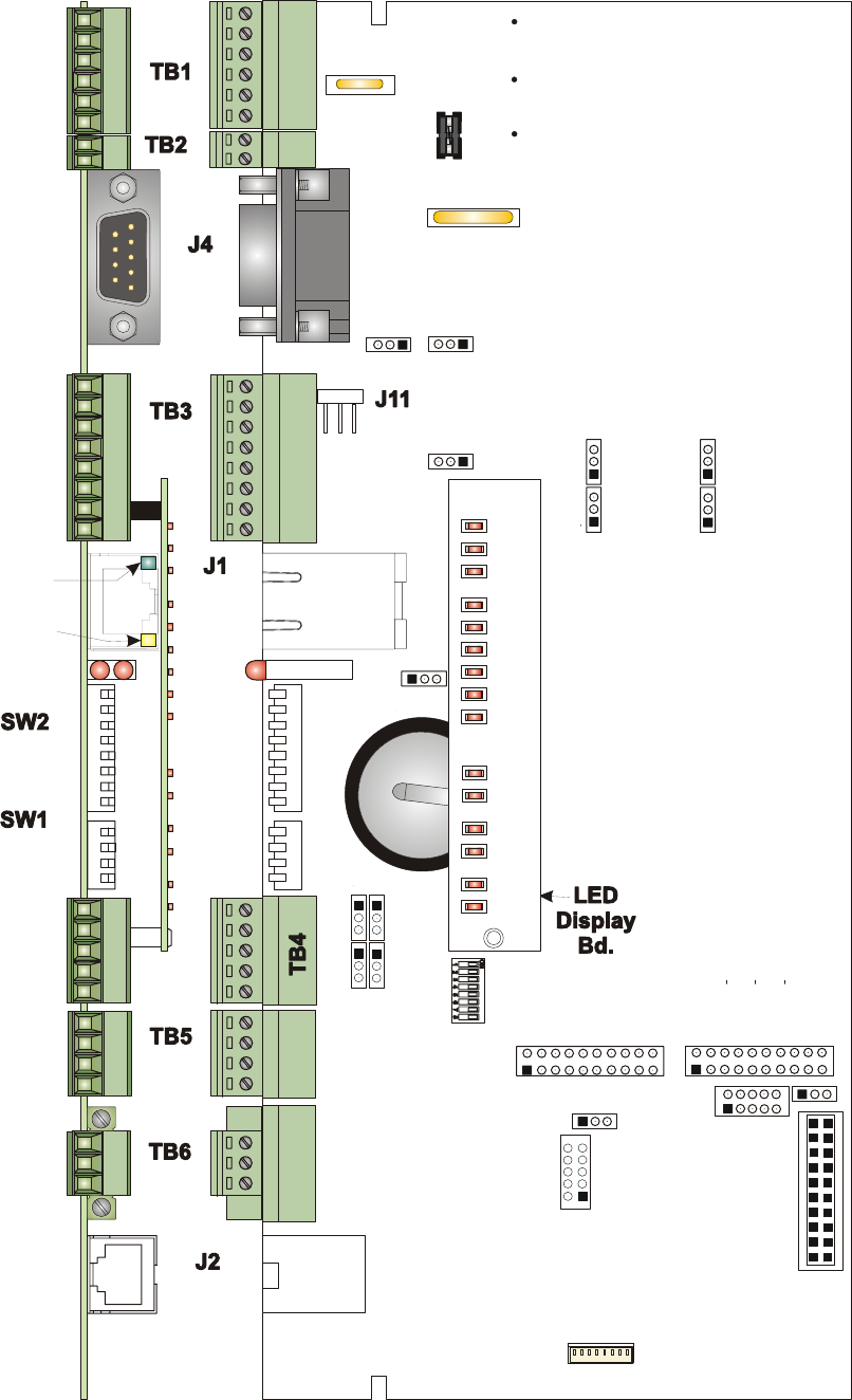
C-2 / Appendix C - Hardware Installation Guide CI-ControlWave Express
S1
1234
123456 78
1
1
2
2
3
4
5
6
RJ-45
RJ-45
W3: 1-2 = Battery Enabled
2-3 = Battery Disabled
W2: 1-2 = COM2 CTS from Port
W5: 1-2 = 12/24V Power Supply
Shut-down Hysterisis
Shut-down Hysterisis
2-3 = 6V Power Supply
W6: 1-2 = 12V Power Supply
Shut-down
Shut-down
2-3 = 6/24V Power Supply
2-3 = COM2 CTS to RTS
W1: 1-2 = COM1 CTS from Port
2-3 = COM1 CTS to RTS
SW3 - COM3 Config.
RS-485 Receiver Biasing & Termination
2-Wire, 4-Wire Selction J5 - COM3
Piggy-back
Radio Intf.
J3 - I/OBUS
Intf. to
CPU Board
P1 WE
J7
MSP430
JTAG
Header
J9
PLD JTAG
Header
J8
Emulation
Header
J3
J5
W14
W16
W7
W1
3 2 1
W18
F3
W2
W3
W8
W6
W5
W15 W12
W13
Pulse
Input
LCD/
Keypad
Power
Power
GND
Sec. Battery Input
Power In +
Aux. Power Out +
Solar Pwr. In +
GND
GND
GND
P1 is only available on
Ultra Low Power CPU/-
System Controller Bds.
NOTE:
1
5
6
1
2
3
4
5
6
7
8
9
1
2
3
4
5
6
7
8
1
2
3
4
5
TXD-/TXD
GND
RXD+
RXD-/RXD
Input
Input
Output
Output TXD+
4
1
2
3
GND
PULSE 1
PULSE 2
Input
Input
Output PULSE
PWR
COM2
RS-232
10/100
Base-T
Ethernet
Port
COM1
RS-232
COM1
RS-232
Configuration
Options
Switch
Recovery
Mode &
COM./Status
LEDs
1
O
N
234
O
N
12345678
Receive
LED
Transmit
LED
TXD
GND
DCD
RXD
DTR
DSR
RTS
CTS
TXD
TXD
GND
GND
DCD
RXD
RXD
Input
Input
Output
Output
Output
Input
Input
Input
Input
Output
Output
Output
Input
Input
DTR
DSR
RTS
CTS
RTD
Input
1
2
3
RTD-
CAUTION:
Damage WILL occur to
the CPU if the Ethernet
network is connected
to connector J2!
RTD EXC
RTD+
COM3
RS-232
RS-485
PG
WD
STA6
STA5
STA4
STA3
STA2
STA1
TX1
RX1
TX3
RX3
TX2
RX2
IDLE
W12 - W16: 1-2 = COM3 RS-232
2-3 = COM3 RS-485
W7: 1-2 = 12/24V Power Fail
Trip Point Hysterisis
Trip Point Hysterisis
2-3 = 6V Power Fail
W8: 1-2 = 12V Power Fail
Trip Point
Trip Point
2-3 = 6/24V Power Fail
Trip Point
NOTE:
J7, J8, J9
Factory Use
W17
RJ-45
Solar Pwr. In and Aux. Power Out
are not available on units equipped
with an Ethernet Port.
Ultra Low Power & Low Power
CPU/System Controller Bds.
Don’t have an Ethernet Port.
NOTE:
Do Not Connect a 24V Solar Panel
to Connector TB1-1 & TB1-2!
Note: W17 is N/A on 24V Systems
Do Not Connect a 24V Solar
Panel to TB1-1 & TB1-2!
W17: 6/12V CPUs
1-2 = 6V S. P. Charging System
2-3 = 12V S. P. Charging System
W17: 12/24V CPUs
W18: COM1 connector
selection
1 to 2 = J4 active
2 to 3 = J11 active
1-2 = 12V S. P. Charging System
2-3 = N/A
NOTE:
J11 normally used
for CW GFC and CW
Express PAC only.
2 = Watchdog
1 = Idle
}
CR1
CR1 2
1
Figure C-2 - CPU/System Controller Bd. Component I.D.
Click here to return to Table of Contents
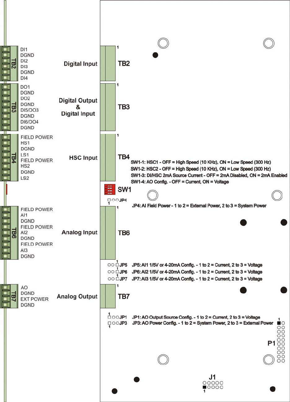
CI-ControlWave Express Appendix C - Hardware Installation Guide / C-3
Figure C-3 – Process I/O Board Component Identification Diagram
Click here to return to Table of Contents

C-4 / Appendix C - Hardware Installation Guide CI-ControlWave Express
Step 1. Hardware Configuration (Continued)
2. Remove the Process I/O Board and the CPU/System Controller Board (as one assembly).
Table C-1 - CPU/System Controller Bd. Switch SW1
Recovery Mode/Local Mode Control
SWITCH Function Setting
SW1-1/2 Recovery/Local Mode * Both ON or OFF = Recovery Mode
SW1 OFF & SW2 ON = Local Mode
SW1-3 Force Recovery Mode ON = Force Recovery Mode (via CW Console)
OFF = Recovery Mode disabled
SW1-4 LED Status ON = Enable Idle LED Status Indication
OFF = Disable Idle LED Status Indication
* = Note: Only the Switch SW1 settings listed in this table, have been tested.
Table C-2 - CPU/System Controller Bd. Configuration Switch SW2 - Assignments
Note: Except for SW2-4, ON = Factory Default
SW# Function Setting - (ON = Factory Default)
SW2-1 Watchdog Enable ON = Watchdog circuit is Enabled
OFF = Watchdog circuit is Disabled
SW2-2 Lock/Unlock
Soft Switches
ON = Write to Soft Switches and FLASH files
OFF = Soft Switches, configurations and FLASH files are locked
SW2-3 Use/Ignore
Soft Switches
ON = Use Soft Switches (configured in FLASH)
OFF = Ignore Soft Switch Configuration and use factory defaults
SW2-4 Core Updump
See Section 3.6
ON = Core Updump Disabled
OFF = Core Updump Enabled via Mode Switch (SW1)
SW2-5 SRAM Control ON = Retain values in SRAM during restarts
OFF = Force system to reinitialize SRAM
SW2-6 System Firmware
Load Control *
ON = Enable remote download of System Firmware
OFF = Disable remote download of System Firmware
SW2-8 Enable WINDIAG ON = Normal Operation (don’t allow WINDIAG to run test)
OFF = Disable boot project (allow WINDIAG to run test)
* = Boot PROM version 4.7 or higher and System PROM version 4.7 or higher
Table C-3 - CPU/System Controller Bd. Switch SW3 Assignments
RS-485 Loopback & Termination Control for COM3
SWITCH
#
RS-485 Function
Switch ON
Setting
SW3-1 TX+ to RX+ Loopback/2-Wire ON – 2-Wire Operation or Loopback Enabled
OFF – 4-Wire Operation & Loopback Disabled
SW3-2 TX− to RX− Loopback/2-Wire ON – 2-Wire Operation or Loopback Enabled
OFF – 4-Wire Operation & Loopback Disabled
SW3-3 100 Ohm RX+ Termination ON – End Nodes Only
SW3-4 100 Ohm RX− Termination ON – End Nodes Only
SW3-7 RX+ Bias (End Nodes/Node)
ON – 4-Wire = Both End Nodes
2-Wire = One End Node Only
OFF – No Bias
SW3-8 RX− Bias (End Nodes/Node)
ON – 4-Wire = Both End Nodes
2-Wire = One End Node Only
OFF – No Bias
SW3-5 & SW3-6 Not Used
Click here to return to Table of Contents

CI-ControlWave Express Appendix C - Hardware Installation Guide / C-5
Step 1. Hardware Configuration (Continued)
3. Make sure that the Lithium Backup Battery has been enabled, i.e., Backup Battery
Jumper W3 on the CPU/System Controller Assembly should be installed on jumper
posts 1-2). Configure the CPU/System Controller Board DIP-Switches and Jumpers.
Tables C-1 through C-3 provides overviews of the switch settings (see Figure C-2).
Configure the Process I/O Board’s DIP-Switches and Jumpers (see Figure C-3). After
configuring the Jumpers and DIP-Switches, install the Process I/O Board and the
CPU/System Controller Board (as one assembly) into the enclosure.
4. Configure/Connect appropriate communication port(s) (see Section 2.3.3.2). Connect
COMM. Port 1 (Local Port) or 2 of the ControlWave Express (depending on CPU/System
Controller Board Switch SW2 settings - see Section 2.3.3.1) to a Communication Port of
a PC (typically PC COMM. Port 1). Note: Also see Section 2.4.4.
A ControlWave Express can be configured as a Master or Slave node on either a
MODBUS network or a BSAP network. A variety of communication schemes are
available. Three communication ports are contained on the standard CPU/System
Controller Board. These communication ports are designated as follows:
CPU/System Controller Board:
COM1 - Port 1: J4 (9-Pin Male D-Sub) or J11 (3-Pin Male connector) - RS-232 (choice
of connector determined by setting of jumper W18.)
COM2 - Port 2: TB3 (8-Pin Term. Block) RS-232
COM3 - Port 3: TB3 (5-Pin Term. Block) RS-232/RS-485 - Configured by Jumpers W12
through W16 (When set for RS-485 operation, COM3 is used to
configure Receiver Biasing and Termination.)
Communication Ports COM1, COM2 and COM3 support serial asynchronous operation
as listed above. Any communication port (COM1, COM2 or COM3) can be configured for
local communications, i.e., connected to a PC loaded with ControlWave Designer and
OpenBSI software. The pin labels for the various RS-232/485 interface connectors are
provided in Tables C-4A and C-4B.
RS-232 & RS-485 Interfaces
ControlWave Express RS-232 & RS-485 communication schemes are discussed herein.
RS-232 Ports
An RS-232 interface supports Point-to-Point, half-duplex and full-duplex
communications (20 feet maximum, using data quality cable). Half-duplex
communications supported by the ControlWave Express utilize MODBUS or BSAP
protocol, while full-duplex is supported by the Point-to-Point (PPP) protocol.
ControlWave Express RS-232 ports utilize a “null modem” cable (Figure C-4 - Top) to
interconnect with other devices such as a PC, printer, a ControlWave-series unit (except
CW_10/30/35) when the ControlWave Express is communicating using the full-duplex
PPP protocol. A half-duplex cable (Figures C-4A - Bottom) may be utilized when the
ControlWave Express is connected to a ControlWave series unit (except CW_10/30/35).
If communicating with a Bristol series 3305, 3310, 3330, 3335 or CW_10/30/35
RTU/DPC, one of the cables shown in Figure C-4B must be used. Refer to Figure C-4C
to connect ControlWave serial RS-232 port COM2 to either an external modem or
external radio. When interfacing to Port COM3 of a ControlWave unit, or to COM5 or
Click here to return to Table of Contents
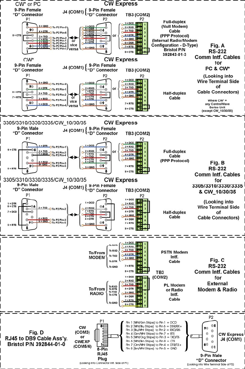
C-6 / Appendix C - Hardware Installation Guide CI-ControlWave Express
COM6 of a ControlWaveEXP, the cable of Figure C-4D must be used along with the one
of Figure C-4A or C-4B.
Figure C-4 - Communication Port RS-232 Cable Wiring Diagram
Click here to return to Table of Contents

CI-ControlWave Express Appendix C - Hardware Installation Guide / C-7
Step 1. Hardware Configuration (Continued)
Tables C-4A through C-4C provide the connector pin assignments for the Comm. Ports.
Note: The following facts regarding ControlWave Express RS-232 serial
communication ports should be observed when constructing communications
cables:
• DCD must be high to transmit (except when dialing a modem)
• Each RS-232 transceiver has one active receiver while in powerdown mode
(disabled); the DCD signal is connected to the active receiver.
• CTS must be high to transmit.
• When port is set for full-duplex operation - RTS is always ON.
• DTR is always high (when port is active); DTR enables RS-232 Transceivers.
• When port is set for half-duplex operation - CTS must go low after RTS goes low.
• All RS-232 Comm. ports support RTS, DTR, CTS, DCD and DSR control signals.
• All RS-232 Comm. port I/O signals are protected by LCDA12C surge protectors to
±4KV ESD.
Table C-4A - RS-232 Ports (COM1 & 2) Connector Pin Assignments
(COM1 Connector J4 & COM2 Connector TB3)
Pin
#
Signal
RS-232
Description:
RS-232 Signals
1 DCD Data Carrier Detect Input
2 RXD Receive Data Input
3 TXD Transmit Data Output
4 DTR Data Terminal Ready Output
5 GND Power Ground
6 DSR Data Set Ready Input
7 RTS Request To Send Output
8 CTS Clear To Send Input
9 - -
Table C-4B - RS-232 Port (COM1) Alternate Connector
(COM1 Connector J11)
Pin
#
Signal
RS-232
Description:
RS-232 Signals
1 GND Power Ground
2 RXD Receive Data Input
3 TXD Transmit Data Output
NOTE: Choice of COM1 connectors (J4 or J11) determined by jumper W18.
Table C-4C - RS-2 32/RS-485 Port (COM3) Connector Pin Assignments
(COM3 Connector TB4)
Pin
#
Signal
RS-232
Description:
RS-232 Signals
Signal
RS-485
Description
RS-485 Signal
1 - - RXD+ Receiver Data + Input
2 RXD Receive Data Input RXD− Receiver Data − Input
3 TXD Transmit Data Output TXD− Transmit Data − Output
4 - - TXD+ Transmit Data + Output
5 GND Power Ground GND Ground
Click here to return to Table of Contents

C-8 / Appendix C - Hardware Installation Guide CI-ControlWave Express
Step 1. Hardware Configuration (Continued)
RS-485 Ports
ControlWave Express RTUs can use an RS-485 communication port for local network
communications to multiple nodes up to 4000 feet away. Since this interface is intended for
network communications, Table C-5 provides the appropriate connections for wiring the
master, 1st slave, and nth slave. Essentially, the master and the first slave transmit and
receive data on opposite lines; all slaves (from the first to the "nth") are paralleled (daisy
chained) across the same lines. The master node should be wired to one end of the RS-485
cable run. A 24-gauge paired conductor cable, such as Belden 9843 should be used. Note:
Only half-duplex RS-485 networks are supported
Receiver biasing and termination as well as 2-wire or 4-wire selection are enabled by an
eight-position DIP-Switch (SW3) situated on the CPU/System Controller Board.
Table C-4C provides connector pin assignments for CPU/System Controller Board port
COM3. Table C-3 provides the RS-485 termination and loopback control Switch Settings for
COM3 when it has been configured for RS-485 communications.
To ensure that the “Receive Data” lines are in a proper state during inactive transmission
periods, certain bias voltage levels must be maintained at the master and most distant
slave units (end nodes). These end nodes also require the insertion of 100-Ohm terminating
resistors to properly balance the network. Secondary Communication Board switches must
be configured at each node to establish proper network performance. This is accomplished
by configuring CPU/System Controller Bd. Switch SW3 (COM3) so that the 100-Ohm
termination resistors and biasing networks are installed at the end nodes and are removed
at all other nodes on the network (see Table C-5).
Table C-5 - RS-485 Network Connections
(see Table C-4C ControlWave Express RS-485 Port Pin # Assignments)
From
Master
To 1st
Slave
To nth
Slave
TXD+ RXD+ RXD+
TXD− RXD− RXD−
RXD+ TXD+ TXD+
RXD− TXD− TXD−
GND/ISOGND*
GND/ISOGND* GND/ISOGND*
* ISOGND with Isolated RS-485 Ports Only!
Note: Pins 1, 2, 3, 4 & 9 of BBI Series 3305, 3310, 3330, 3335 & 3340 RTU/DPC RS-485 Comm.
Ports are assigned as follows: 1 = TXD+, 2 = TXD-, 3 = RXD+, 4 = RXD- & 9 = ISOGND.
Note: For Loopback & Termination Control: Use SW3 on CPU/System Controller Board to
configure COM3.
Ethernet Port
ControlWave Express CPU/System Controller Boards can contain one Ethernet Port that
utilizes a 10/100Base-T RJ-45 modular connector (J1) and typically provides a shielded
twisted pair interface to an Ethernet Hub.
A typical Ethernet Hub provides eight (8) 10/100Base-T RJ-45 Ports (with Port 8 having the
capability to link to another Hub or to an Ethernet communications port). Both ends of the
twisted pair Ethernet cable are equipped with modular RJ-45 connectors. These cables have
Click here to return to Table of Contents
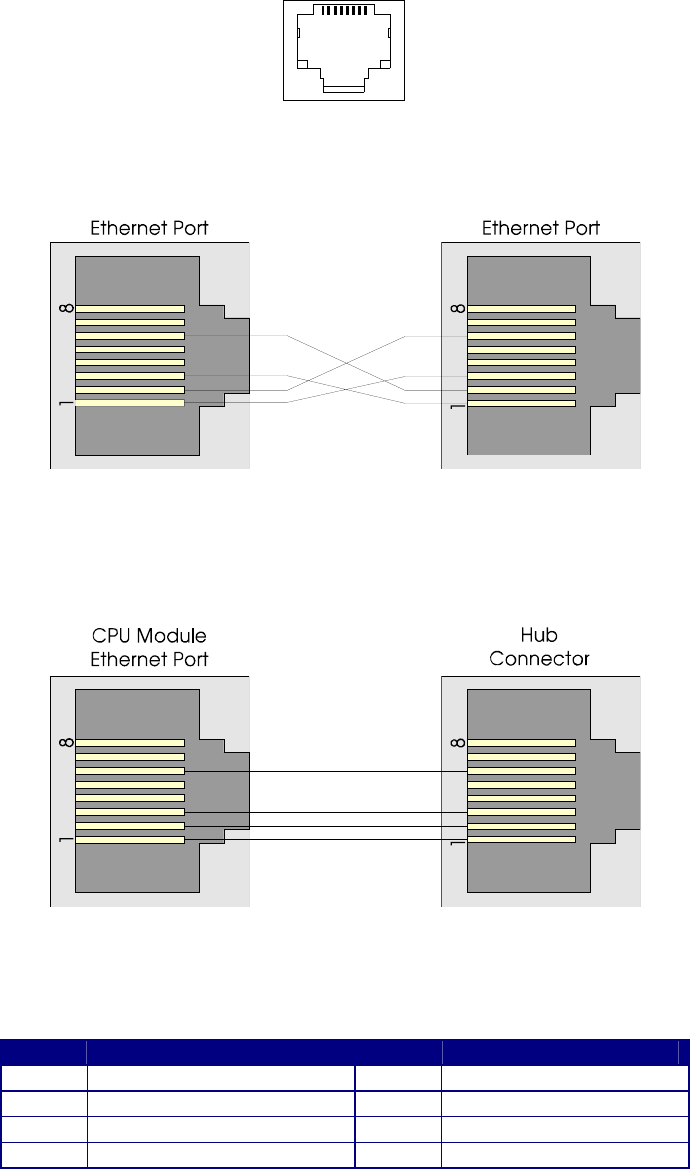
CI-ControlWave Express Appendix C - Hardware Installation Guide / C-9
a one-to-one wiring configuration as shown in Figure C-7. Table C-6 provides the
assignments and definitions of the 8-pin 10/100Base-T connector.
It is possible to connect two nodes in a point-to-point configuration without the use of a
Hub. However, the cable used must be configured such that the TX+/- Data pins are
connected to the RX+/- Data pins (swapped) at the opposite ends of the cable (see Figure C-
7).
18
Looking into
receptacle
Figure C-5 - RJ-45 Connector (Ethernet Port) J1 on CPU/System Controller Board
Figure C-6 - Point-to-Point 10/100Base-T Ethernet Cable
The maximum length of one segment (CPU to Hub) is 100 meters (328 feet). The use of
Category 5 shielded cable is recommended.
Figure C-7 - Standard 10/100Base-T Ethernet Cable
(CPU/System Controller Board to Hub)
Table C-6 - Ethernet 10/100Base-T Pin Assignments
Pin # Description Pin # Description
1 Transmit Data+ (Output) 5 Not Connected
2 Transmit Data- (Output) 6 Receive Data- (Input)
3 Receive Data+ (Input) 7 Not Connected
4 Not Connected 8 Not Connected
Note: TX & RX are swapped at Hub’s.
Click here to return to Table of Contents
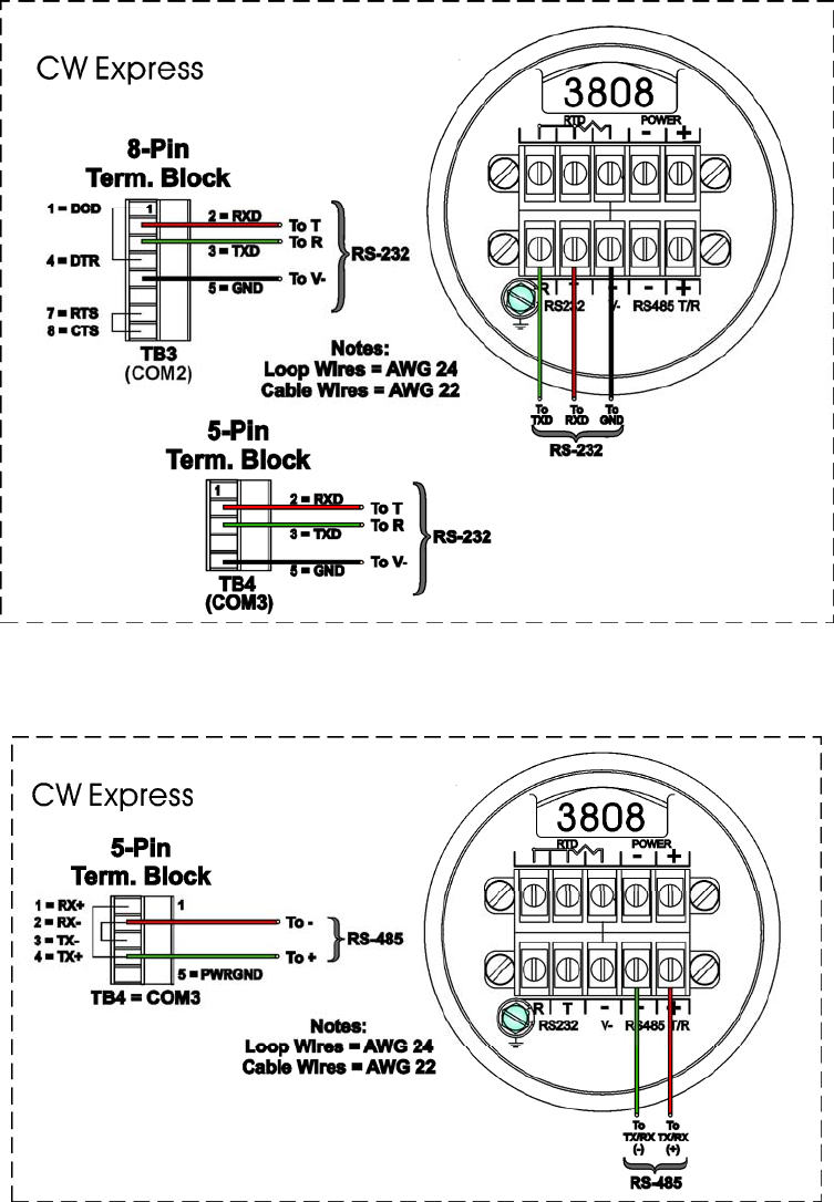
C-10 / Appendix C - Hardware Installation Guide CI-ControlWave Express
Step 1. Hardware Configuration (Continued)
5. Install I/O wiring to the Process I/O Board and CPU/System Controller Board (see
Figures C-11 and C-12 and Section 2.3.4 if required). Install a communications cable
between the ControlWave Express and a Model 3808 Transmitter (Network of
Transmitters) if required (see Figures C-8 through C-10). Figures C-8 and C-9 detail the
RS-232 and RS-485 wiring connections required between the ControlWave Express and
the Model 3808 Transmitter.
Figure C-8 - Model 3808 Transmitter to ControlWave Express
RS-232 Comm. Cable Diagram
Figure C-9 - Model 3808 Transmitter to ControlWave Express
RS-485 Comm. Cable Diagram
Click here to return to Table of Contents
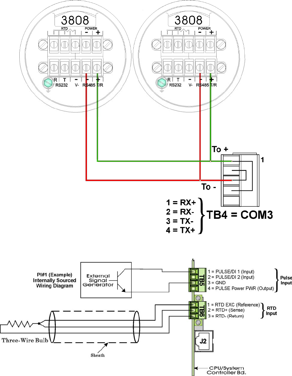
CI-ControlWave Express Appendix C - Hardware Installation Guide / C-11
Step 1. Hardware Configuration (Continued)
Up to two (2) Model 3808 Transmitters can be connected to a ControlWave Express via
a half duplex RS-485 Network. An illustration of this network is provided in Figure C-
10.
Figure C-10 - ControlWave Express to 3808s - RS-485 Network Diagram
Figure C-11 - CPU/System Controller Board Field I/O Wiring Diagrams
Click here to return to Table of Contents
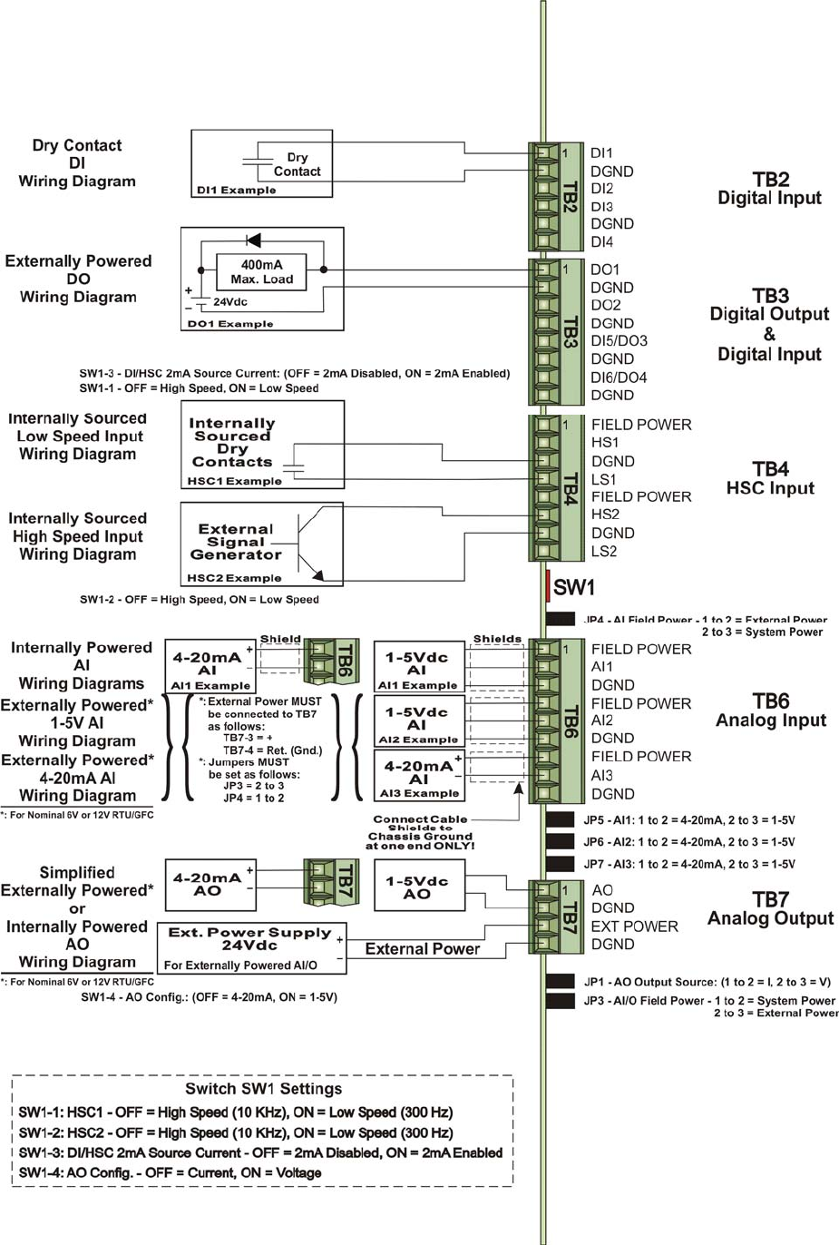
C-12 / Appendix C - Hardware Installation Guide CI-ControlWave Express
Figure C-12 – Process I/O Board Field I/O Wiring Diagrams
Click here to return to Table of Contents

CI-ControlWave Express Appendix C - Hardware Installation Guide / C-13
Step 1. Hardware Configuration (Continued)
6. Install a ground wire between the Enclosure/Chassis and a known good Earth Ground.
ControlWave Express Enclosures are not provided with a Ground Lug. A ground wire
(#4 AWG Max. wire size) must be run between the Enclosure/Chassis via one or more
mounting screws (see Figure C-1) and a known good Earth Ground. The following
considerations are provided for the installation of ControlWave Express system grounds
(see S1400CW):
• Earth Ground wire size should be #4 AWG. It is recommended that stranded copper
wire is used and that the length should be as short as possible.
• This ground wire should be clamped or brazed to the Ground Bed Conductor (that is
typically a stranded copper AWG 0000 cable installed vertically or horizontally).
• The wire end that is to be fastened to the ControlWave Express should be crimped to
a Terminal Ring/Lug and soldered. Note: Use a high wattage Soldering Iron.
• The ground wire should be run such that any routing bend in the cable has a
minimum radius of 12-inches below ground and 8-inches above ground.
7. If required, install the RTD Probe (see Section 2.3.5).
8. Connect DC Power wiring to the ControlWave Express CPU/System Controller Board
(see Sections 2.3.7.1 & 2.3.7.2).
CPU/System Controller Board Connector TB1 power wiring assignments are provided
as follows:
TB1-1 = Solar Power In+
TB1-2 = GND Chassis Ground – CHASSIS - (Solar Power − Return)
TB1-3 = (+VIN) (+5.4Vdc to +16V dc for 6V bulk) (+11.4Vdc to +16.0Vdc for 12V bulk)
(+21.8Vdc to +28.0Vdc for 24V bulk)
TB1-4 = GND Chassis Ground – CHASSIS
TB1-5 = Aux. Power Out + (for external radio/modem)
TB1-6 = GND Chassis Ground – CHASSIS - (for radio/modem)
9. Apply power to the ControlWave Express. Continue with Steps 2 through 7 below (and
Section 2.4.1) and the ControlWave Express will be ready for on line operation.
Step 2. Software Installation on the PC Workstation
ControlWave Designer software must be installed on the PC if the ControlWave Express is
being utilized for an application, other than the standard one. This is accomplished by
installing the ControlWave Designer Package from the Open BSI CD ROM.
You must install the Open BSI Network Edition. For information on minimum system
requirements and more details on the installation, see the installation procedure in
Chapter 2 of the Open BSI Utilities Manual (document # D5081).
If you have an older version of ControlWave Designer already installed:
Beginning with ControlWave Designer Version 3.3, the copy protection key (dongle) is NOT
required. Prior to installing ControlWave Designer 3.3 or newer, you MUST remove the
hardware dongle from the parallel port of your PC workstation. Otherwise, when you
Click here to return to Table of Contents
C-14 / Appendix C - Hardware Installation Guide CI-ControlWave Express
subsequently start ControlWave Designer, it will operate only in ‘DEMO’ mode, and will
limit the available system resources.
IMPORTANT:
When you start ControlWave Designer, you will be reminded to register the
software. Unregistered software can only be used for a maximum of 30 days. For
more information on the registration process, see Chapter 2 of the Open BSI
Utilities Manual (document# D5081).
Step 3. Establish Communications using either LocalView, NetView, or TechView
and Run the Flash Configuration Utility
Communications must be established with the ControlWave Express using either
LocalView, NetView, or TechView.
The ControlWave Express ships from the factory with a default Flash configuration. Most
users will need to edit this configuration to set the IP address (if using PPP), BSAP local
address, user accounts, and port parameters. This can be done in one of two ways:
• Either open the supplied Flash Configuration Profile (FCP) file and modify it, directly in
the Flash Configuration Utility, or in a text editor,
• Or retrieve existing Flash Parameters directly from the unit, and edit them in the Flash
Configuration Utility.
Detailed information on the Flash Configuration Utility and LocalView is included in
Chapter 5 of the Open BSI Utilities Manual (document # D5081). NetView is described in
Chapter 6 of that same manual. TechView is described in the TechView User’s Guide
(document# D5131).
Step 4. Creation of the Application-Specific Control Strategy
You can create your own application-specific control strategy using ControlWave Designer.
This involves opening a new project using the ‘CWMicro’ template, defining I/O points using
the I/O Configurator, and creating a program using one or more of the five supported IEC
61131 languages (FBD, ST, SFC, LD, or IL). Some of these languages are text-based, others
use graphical diagrams. The choice is up to you, depending upon your particular
application.
The ControlWave MICRO Quick Setup Guide (document # D5124) includes a simple LD
example. Additional examples are included in the manual, Getting Started with
ControlWave Designer (document # D5085). More detailed information about ControlWave
Designer and IEC 61131 is included in the ControlWave Designer Reference Manual
(document # D5088).
The ACCOL3 Firmware Library, which is automatically accessible through the template
referenced above, includes a series of function blocks which perform a variety of process
control and communication functions. These can be included within your program to
perform various duties including PID control, alarming, calculations, etc. Detailed
information about each function block is included in the ControlWave Designer on-line help
files.
Click here to return to Table of Contents
CI-ControlWave Express Appendix C - Hardware Installation Guide / C-15
On the variables declaration page(s) in ControlWave Designer, you will need to mark any
variable you want to make accessible to external programs, such as Open BSI’s DataView
utility, as “PDD”. Similarly, any variables which should be collected into a database, or
exported using the OLE for Process Control (OPC) Server must be marked as “OPC.”
Variables marked as OPC can be built into a text file by the OpenBSI Signal Extractor.
The text file can then be used in the creation of a database for human machine interface
(HMI) software such as OpenEnterprise or Iconics’ Genesis. These HMI software packages
require that the "Datatype conversion enable" option be selected when generating the
file using Signal Extractor. Information about the OpenBSI Signal Extractor is included in
Chapter 12 of the Open BSI Utilities Manual (document # D5081).
Once the program has been created, it is assigned to an executable task. The entire project
is then saved and compiled.
NOTE: From this point on, the order of steps may be varied, somewhat,
depending upon the requirements of the user's application.
Step 5. Create Your Own Application-Specific Web Pages (Optonal)
The ControlWave Express RTU supports a standard set of web pages for configuration
purposes. If you create your own application program, you may create your own web pages
using Bristol ActiveX controls discussed in the Web_BSI Manual (document # D5087).
You can use whichever HTML creation package you want to create the pages, however, all
ControlWave Express related web pages (whether standard or user-created) must be viewed
within Microsoft® Internet Explorer. Web pages are stored on a PC workstation.
Step 6. Create an Open BSI Network Containing the ControlWave Express, or
ADD the ControlWave Express to an Existing Open BSI Network
In order for the ControlWave Express unit to function as part of a Bristol network, it is
necessary to include it in the Bristol network.
If no Bristol network exists:
You need to run Open BSI’s NetView software on the PC workstation in order to define
a Bristol network. A series of software wizards are used to define a Network Host PC, a
network, and the RTUs (controllers) assigned to the network. Finally, communication
lines must be specified which handle the address assigned to the ControlWave Express.
Chapters 3 and 4 of the Open BSI Utilities Manual (document # D5081) include ‘quick
start’ examples for performing these steps. More detailed information is included in the
NetView chapter (Chapter 6) of D5081.
If a Bristol network already exists:
You will need to add the ControlWave Express RTU to the existing network using
NetView’s RTU Wizard. Chapter 6 of the Open BSI Utilities Manual (document #
D5081) includes different sub-sections depending upon whether you are adding the unit
to a BSAP network, or an IP network.
Step 7. If applicable, download new or modified control strategy (OPTIONAL)
If you modify a standard ControlWave Express program, or create your own program,
compile and download the new or modified program into the unit, using either
ControlWave Designer, or the Open BSI 1131 Downloader. In this case, you download
the control strategy into the BOOT project area of FLASH memory; this ensures that if
Click here to return to Table of Contents
C-16 / Appendix C - Hardware Installation Guide CI-ControlWave Express
the ControlWave Express is reset, or if there has been a failure of the backup battery,
the control strategy can be restarted from the beginning, i.e. from the BOOT project in
FLASH memory.
Downloading the Application
Any ControlWave Express must have a configured ControlWave project (application) before it
can be placed into operation. This will require connection of the ControlWave Express to a PC
running ControlWave Designer and OpenBSI software. Configuration of the application must
be performed by an individual familiar with the various programming tools. The following
software user documentation is referenced:
Getting Started with ControlWave Designer Manual - D5085
ControlWave Designer Reference Manual - D5088
Open BSI Utilities Manual - D5081
Web_BSI Manual - D5087
ControlWave Designer Programmer’s Handbook – D5125
An application download can be initiated from ControlWave Designer, or from the OpenBSI
1131 Downloader.
1. Make sure that the CPU/System Controller Board’s Mode Switch (SW2) is set in ‘Local
Mode,’ i.e., SW1-1 in the OFF position and SW1-2 in the ON position.
Note: From the factory, COM1 defaults to 115.2 kbd (RS-232) using the BSAP
Protocol. Do not connect COM1 to a PC unless the PC’s RS-232 port in
question has been configured for BSAP operation.
2. Once the ControlWave Express project has been defined and the communications and
configuration parameters have been set, perform the download from either ControlWave
Designer (see D5088 - Chapter 11) or the Open BSI 1131 Downloader (see D5081 - Chapter
7).
3. After the download has been completed leave the CPU/System Controller Board’s Mode
Switch (SW1) set in ‘Local Mode,’ i.e., SW1-1 in the OFF position and SW1-2 in the ON
position.
LED & LCD Display Checks
CPU/System Controller Boards for the ControlWave Express, ControlWave ExpressPAC,
ControlWave GFC, ControlWave GFC Plus, and ControlWave Corrector are equipped with
two red LEDs that provide the following status conditions when lit: WD (CR1 - Right) –
Indicates Watchdog condition has been detected & IDLE (CR1 - Left) - Indicates the CPU
has free time at the end of its execution cycle. Normally, the Idle LED should be ON most of
the time (unless disabled). When the Idle LED is OFF, it indicates that the CPU has no free
time, and may be overloaded.
ControlWave Express CPU/System Controller Boards ONLY are also equipped with a
piggyback mounted LED Board. These LEDs provide the following status conditions when
lit:
PG (Red) – ON = Power Good
WD (Red) - ON = Watchdog Condition - OFF = Normal Operation
Click here to return to Table of Contents
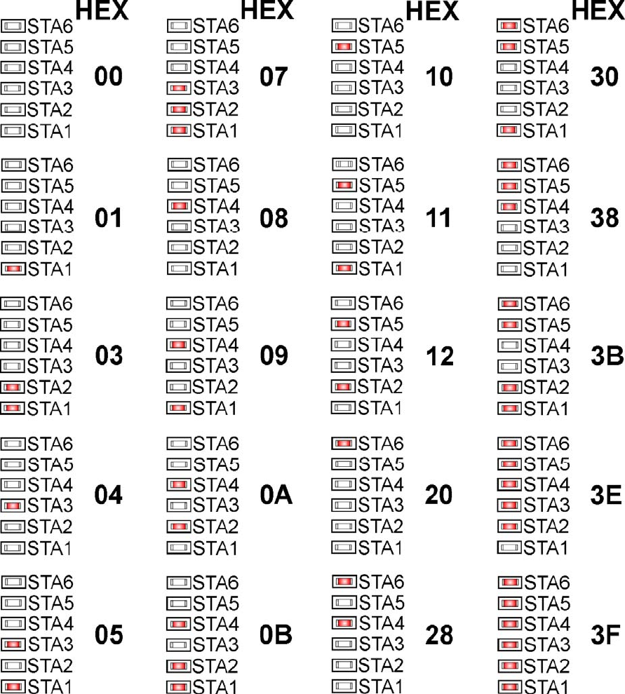
CI-ControlWave Express Appendix C - Hardware Installation Guide / C-17
IDLE (Red) - the CPU has free time at the end of its execution cycle and may be overloaded
TX1, TX2, TX3 (Red) - transmit activity on COM1, COM2 & COM3 (respectively)
RX1, RX2, RX3 (Red) - receive activity on COM1, COM2 & COM3 (respectively)
Six Status LEDs (Red) - provide run time status codes (see Table C-7 and Figure C-13)
Normally, the Idle LED should be ON most of the time (unless disabled). When the Idle
LED is OFF, it indicates that the CPU has no free time, and may be overloaded.
Ethernet Port Connector J1 on the CPU/System Controller Board contains two LEDs that
indicate transmit (yellow) and receive (green) activity when lit.
Operation and diagnostic messages are posted to the six Status LEDs (see Figure C-13 and
Table C-7) and, if present, to the optional LCD Display (see Table C-7).
Figure C-13 - CPU/System Controller LED Board - LED Hexadecimal Codes
Click here to return to Table of Contents

C-18 / Appendix C - Hardware Installation Guide CI-ControlWave Express
(See Table C-7 for Definitions)
Table C-7 - System Status Codes on LCD Display
& LEDs on CPU/System Controller Board’s LED Board.
LED
6
STA6
LED
5
STA5
LED
4
STA4
LED
3
STA3
LED
2
STA2
LED
1
STA1
Status
In
Hex
LCD
Disp.
Indication
Definition
0 0 0 0 0 0 00 Blank Application Running
0 0 0 0 0 1 01 DIAG Unit in Diagnostic Mode
0 0 0 0 1 1 03 R DIAG Unit Running Diagnostics
0 0 0 1 0 0 04 FWXSUM
Flash XSUM Error
0 0 0 1 0 1 05 DEVERR Error Initializing Application Device
0 0 0 1 1 1 07 FLASH Flash Programming Error
0 0 1 0 0 0 08 FACT Using Factory Defaults *
0 0 1 0 0 1 09 BATT Battery Failure Detected *
0 0 1 0 1 0 0A STRTUP Currently Loading the Boot Project
0 0 1 0 1 1 0B INIT System Initialization in Progress
0 1 0 0 0 0 10 RECOV Waiting in Recovery Mode
0 1 0 0 1 0 12 RAMERR Error Testing SRAM
1 0 0 0 0 0 20 STOP Application Loaded
1 0 1 0 0 0 28 HALT Stopped at a Break Point
1 1 0 0 0 0 30 NO APP No Application Loaded
1 1 1 0 0 0 38 BREAKP Running with Break Points
1 1 1 0 1 1 3B POWERD Waiting for Power-down (after NMI)
1 1 1 1 1 0 3E UPDUMP
Waiting for Updump to be Performed
1 1 1 1 1 1 3F NOTRUN Unit Crashed (Watchdog Disabled)
* = Flashed at startup
Click here to return to Table of Contents
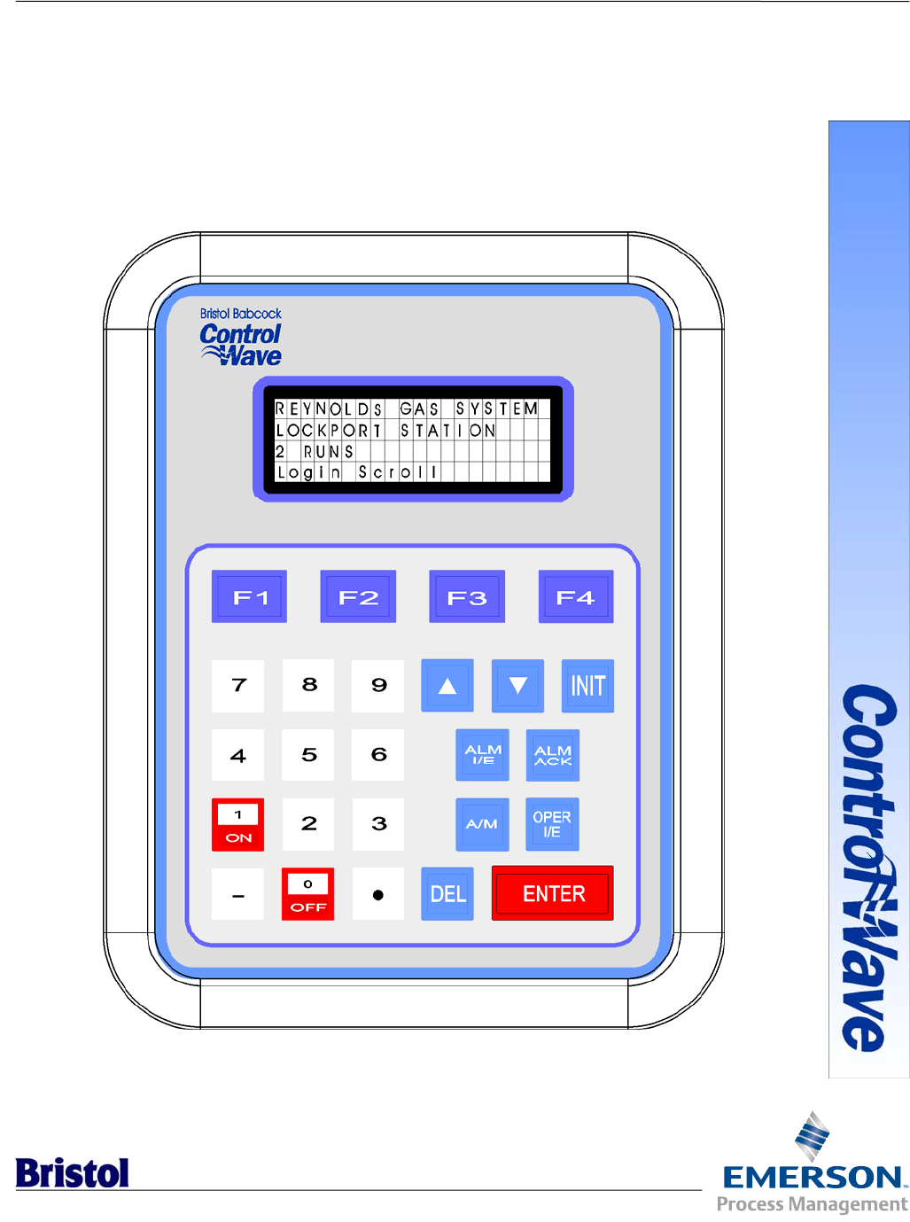
www.EmersonProcess.com/Bristol
Instruction Manual
CI-ControlWave Express
Oct., 2006
ControlWave Ex
p
ress
ControlWave Express DISPLAY/KEYPAD
ASSEMBLY - GUIDE
Appendix E
Click here to return to Table of Contents
CI-ControlWave Express Appendix E – Display/Keypad Contents / 0 - 1
APPENDIX E
ControlWave Express
Display/Keypad Assembly Guide
TABLE OF CONTENTS
SECTION TITLE PAGE #
E1.1 OVERVIEW ................................................................................................................... E-1
E2.1 DISPLAY FUNCTION BLOCK DESCRIPTION......................................................... E-2
E2.1.1 DISPLAY Function Block Parameters ......................................................................... E-2
E3.1 PREPARING THE ControlWave PROJECT................................................................ E-3
E4.1 USING THE KEYPAD .................................................................................................. E-4
E4.1.1 Scrolling.......................................................................................................................... E-5
E4.1.2 Signing-On ..................................................................................................................... E-6
E4.1.3 Using the Clock Functions ............................................................................................ E-7
E4.1.3.1 Changing the Time ........................................................................................................ E-8
E4.1.3.2 Changing the Date......................................................................................................... E-8
E4.1.4 Choosing a Variable List from the List Menu.............................................................. E-8
E4.1.5 Moving Through a Variable List................................................................................... E-9
E4.1.6 Changing Variable Parameters .................................................................................... E-9
E4.1.7 Signing-Off ................................................................................................................... E-12
E5.1 KEYPAD IDENTIFICATION & INSTALLATION INFO......................................... E-13
NOTE:
The Dual-button Display/Keypad Assembly is discussed at the end of Chapter 2
(see Section 2.4.5.2).
Click here to return to Table of Contents
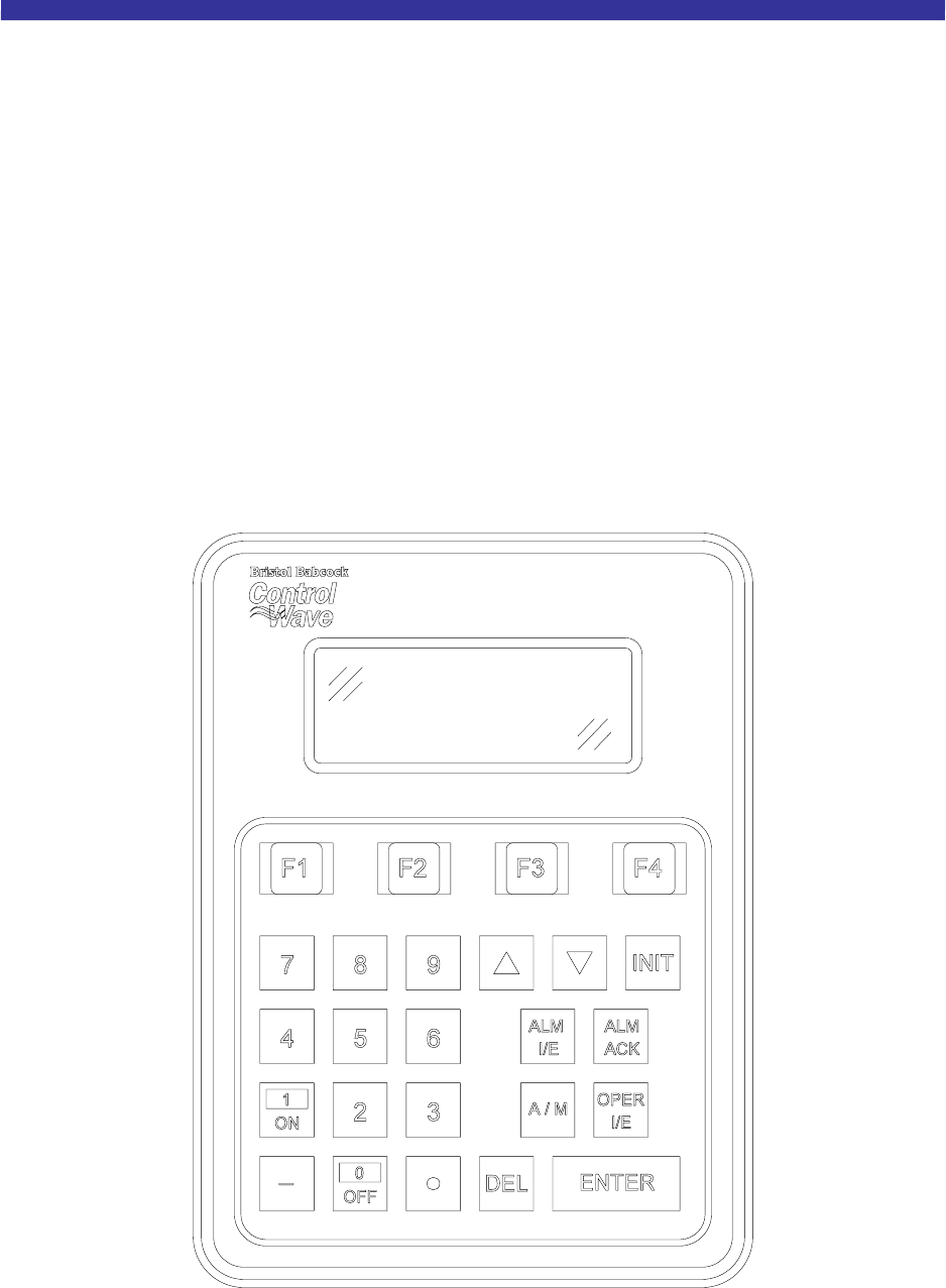
CI-ControlWave Express Appendix E - Display/Keypad / E-1
Appendix E
DISPLAY/KEYPAD ASSEMBLY GUIDE
E1.1 OVERVIEW
Bristol Display/Keypad assemblies provide a built-in, local, user interface for the
ControlWave Express These assemblies allow an operator or engineer to view and modify
variable values and associated status information, via an ACCOL3 Function Block.
Variables can include inputs, process variables, calculated variables, constants, setpoints,
tuning parameters and outputs used in a measurement or control application. Status bits
include alarm state, alarm acknowledge, control, manual, and questionable data.
Setting up the Display/Keypad is a simple matter of configuring a Display Function Block
in the ControlWave Designer project.
The Display/Keypad is comprised of a four line by twenty character liquid crystal display,
with adjustable LCD Contrast, and a 25 button membrane key matrix. Each key has a
microswitch for positive tactile feedback. This means that as you firmly depress the keys,
you will feel it click as it engages. In the case of the ControlWave Express, the
Display/Keypad is located externally to the unit.
Figure 1 - Display/Keypad Assembly – 25 Button Keypad & 4 X 20 Display
Click here to return to Table of Contents

E-2 / Appendix E - Display/5x5Keypad CI-ControlWave Express
Display/Keypad Assemblies are supported by Automatic Mode and Manual Mode.
Automatic Mode
In Automatic Mode a set of screens (based on the application load) are displayed. The
application programmer provides strings for the opening screen. From there the firmware is
responsible for displaying the screens and responding to key presses. Screens are fixed and
start off with an opening screen, which displays user information passed into the function
block. Users can view a list to select which list is to be scrolled. Once the list to be scrolled
has been selected, the user can scroll through the list by pressing the down arrow key. List
elements will be displayed automatically, scrolling at a predetermined rate (determined by
iiScrollTime). The user may pause on a variable by pressing the right arrow key. Pressing
the right arrow key again will cause the list to start scrolling again.
The essence of Automatic Mode is that the user can supply inputs into the function that
will determine which list can be displayed, but cannot change the menu or display. The
user is allowed to select a list and to start/stop scrolling.
Manual Mode
In Manual Mode the programmer is responsible for creating each screen and displaying the
next desired screen, based on key inputs. The programmer has access to all lines of the
display and can provide any string that he/she desires to display. Special formats that must
be adhered to that allow the programmer to display what they want on the screen are
provided in the description of iaScrnSruct in the ACCOL 3 Display function block within
ControlWave Designer’s On-Line Help. It should be noted that currently, Manual Mode
does not support reading Keypad keypresses. Note: Manual Mode operation requires
ControlWave Firmware 4.50 or newer.
If you're setting up the keypad, follow the configuration instructions provided in Section E3
of this appendix.
If your keypad has already been set up, Section E4 will tell you how to use the keypad and
interpret the display.
E2.1 DISPLAY FUNCTION BLOCK DESCRIPTION
Keypad and display control/configuration are handled by the DISPLAY Function Block.
This function block allows an operator to view/change variable data or to be allowed to
scroll through lists of variable data based upon their login privileges.
In order for the keypad and display to operate, the ControlWave Designer project must
include a properly configured DISPLAY Function Block. Use ControlWave Designer to
configure this function block and assign the parameters according to the four steps covered
in Section 3.
E2.1.1 DISPLAY Function Block Parameters
Referring to Figure 2, various DISPLAY Function Block Parameters are available. For
information on configuring the Display Function Block, please reference on-line help in
ControlWave Designer.
Click here to return to Table of Contents
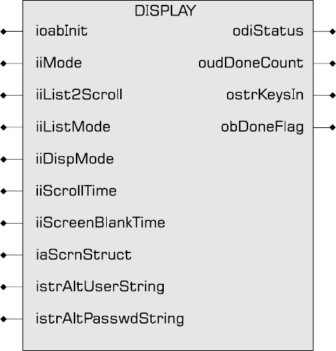
CI-ControlWave Express Appendix E - Display/Keypad / E-3
Figure 2 - ACCOL3 DISPLAY Function Block Parameters
E3.1 PREPARING THE ControlWave PROJECT
In order for the keypad and display to operate, the ControlWave Designer project must
include a properly configured Display Function Block. Once the Keypad is operating, a user
who has signed on with a password can scroll through the names of variable lists and
choose a list to read or change. Use Up Arrow and Down Arrow keys to select the Username
and use the numeric keys to enter your password. The steps that follow describe how to
configure this function block.
Step 1: Creating the Identifier Display
The Identifier Display is the first display to appear when the Display Function Block is
initialized and begins to execute. This display will look similar to Figure 3. Each of the first
three lines of the display contains the text value of a string variable. These string variables
are created utilizing iaScrnStruct parameters of the Display Function Block (See Figure 2)
and your computer keyboard. Since this is the first display that the user will see, you may
want the display to contain general information such as the node name of the controller or
the process that the controller is monitoring.
The bottom line on the display is called the legend line. It shows which function keys are
currently active and their purpose. Function keys are those keys on the Keypad that are
marked ([F1] through [F4]). Function key assignments are preconfigured and cannot be
changed. Using function keys is described in Section 4, Using the Keypad.
The legend line in Figure 3 shows that the user has two choices: to Log-in (using [F1]) or
scroll (using [F2]).
Click here to return to Table of Contents

E-4 / Appendix E - Display/5x5Keypad CI-ControlWave Express
Figure 3 - Creating the Identifier Message
Step 2: Defining a Scroll List
Once the Keypad is operating properly, you can automatically scroll through a list of
variables created via DISPLAY Function Block Parameters iiList2Scroll and iiListMode.
Scrolling can be done without entering a password. The variables in the list are displayed
one at a time and in the same order in which they were entered in the variable list.
Later, we'll discuss other variable lists that can be accessed with the keypad. To distinguish
this list from others, let's call this variable list the Scroll List.
Enter the number of a variable list to be scrolled. This variable list becomes the Scroll List.
The Scroll List can contain different types of variables (that is, logical, analog and string).
You can create a specific scroll variable list or use any list in the ControlWave Project.
Each variable in the Scroll List will be displayed for the number of seconds defined by the
iiScrollTime parameter. If you don't specify a time for this parameter, the hold time will be
two seconds. If you signed-on and then started scrolling you will be signed-off in 20 minutes
if no keys are pressed. If you don’t want to automatically stop scrolling after 20 minutes,
sign-off (INIT key) before starting scrolling.
Step 3: Assigning Passwords
A valid RTU username/password combination must be entered to go beyond the initial
displays. Passwords can be any combination of numbers up to 16 digits in length, from
0000000000000000 to 9999999999999999. If none are specified, the default values are
system for User-name and 666666 for Password (read/write access).
Step 4: Status Information
Enter a variable name on the odiStatus terminal.
See On Line Help in ControlWave Designer for Status Values.
The next section describes how to use the Keypad to access variable information.
E4.1 USING THE KEYPAD
The Identifier Display is the starting point from which you can go to other displays. It
shows an identification message and the words Login and Scroll at the bottom of the screen
(see Note 1). The identification message may contain the name of the controller, the plant
equipment it is monitoring, or the variables you can expect to see when you use this
display.
Click here to return to Table of Contents
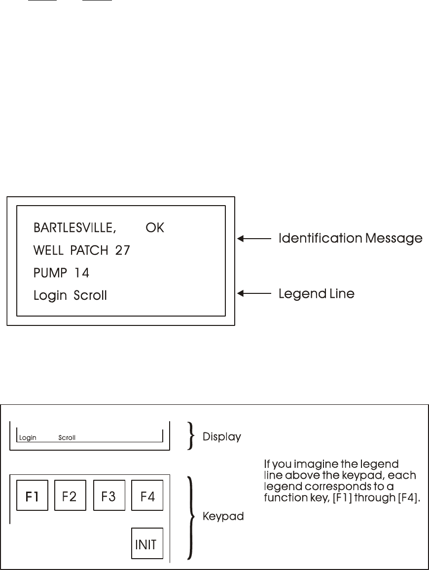
CI-ControlWave Express Appendix E - Display/Keypad / E-5
Note 1 : If your display shows something else, press the [F4] key until you see the words
Login and Scroll on the bottom line.
If your screen is blank, turn the brightness screw clockwise. This screw is located to
the left of the Keypad (looking at the rear of the 25-Button Display/Keypad As-
sembly (see Figure 17). If no letters appear, the controller has not been program-
med properly to operate the keypad.
The words Login and Scroll at the bottom of the screen are on the legend line. It tells you
which function keys (that is, key [F1] through [F4]) are active and their purpose at that
time.
Up to four legends can appear on the legend line. The legend on the far left corresponds to
the function of the [F1] key. The assignment for the [F4] key is on the far right. Keys [F2]
and [F3] are described to the left and right of center. When no legend appears, that function
key is not active at that time. For example, in Figure 4 only [F1] and [F2] are active.
Figure 4 - The Identifier Display
From the Identifier Display, you have two choices. Pressing [F1] will allow you to sign-on if
you have a password. By pressing [F2] you can activate automatic scrolling through a list of
variables.
Figure 5 - Identifier Display Legends and Corresponding Keypad Alignment
for 25 Button Membrane Key Matrix Keypad System
E4.1.1 Scrolling
To begin automatic scrolling, press [F2] from the Identifier Display (Figure 4). Variable in-
Click here to return to Table of Contents
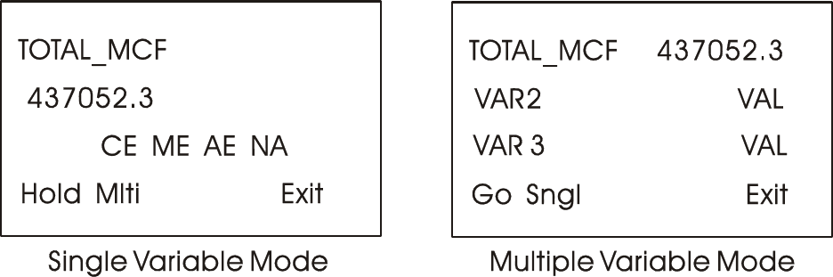
E-6 / Appendix E - Display/5x5Keypad CI-ControlWave Express
formation will appear on the screen and remain there for 1 to 30 seconds (default = 2). The
variable name appears on the first line. The variable value appears on the second line and
status information appears on the third line. An example is shown in Figure 6.
When all variables in the list have been displayed, they will be shown again in the same
order. This is called Single Variable Mode.
Pressing Mlti [F2] activates Multiple Variable Mode. Multiple Variable Mode displays up to
three (3) variables and their values on the screen simultaneously. Pressing Sngl [F2]
terminates Multiple Variable Mode and returns you to Single Variable Mode.
Figure 6 - Scrolling
Press HOLD [F1] to halt scrolling. Changing variable values will continue to be displayed.
Press GO [F1] to resume scrolling.
Press EXIT [F4] to return to the Identifier Display (Figure 4).
E4.1.2 Signing-On
To access the List Menu, you must first sign-on with a proper password. From the
Identifier Display (Figure 4), press [F1]. The screen will look like Figure 7A or 7C. If the
display looks like Figure 7C:
Someone else has already signed on. Go to the paragraph below that starts "Once you
have successfully signed on,…".
If the display looks like Figure 7A:
Select the Username (default = system) by using the Up and Down Arrow Keys. If the
Username system is displayed and no other Username is available (i.e., no others have
been assigned), press [ENTER].
Enter a password using the 0 to 9 keys. For security, asterisks will appear as you enter
the digits. If you make a mistake, press [F1] and try again or use the delete key to
delete the previously pressed key action. The default password is 666666 (used when a
password is not known or no password has been assigned). After typing the password,
press [ENTER].
Click here to return to Table of Contents
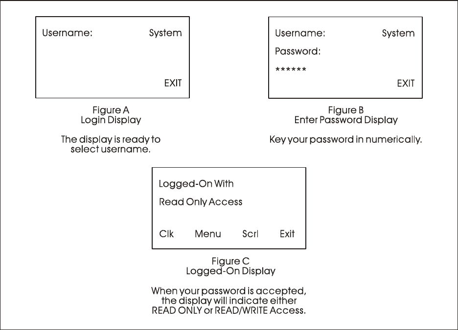
CI-ControlWave Express Appendix E - Display/Keypad / E-7
If your password is not recognized, the asterisks will be erased after you press
[ENTER]. Check your password and try again.
Figure 7 - Logging On
Once the correct password has been entered, the display will look like Figure 7C.
When the second line shows READ/WRITE, you can read and write variable parameters.
When it shows READ ONLY you cannot change variable parameters. You are only permit-
ted to read variable information. If your display shows READ ONLY and you want to
change variable values, sign-off (press the [INIT] key) and log on with a username and
password that provides Read/Write privileges.
Once you have successfully signed on, the legend line will show that you have four options.
You can view and change the time and date of the local clock, access more variable lists,
Scroll, or return to the Identifier Display. Use function keys F1 through F4 to select the
next menu (F1 = Clock, F2 = Menu, F3 = Scroll list & F4 = Exit). Let's start by setting the
local clock.
E4.1.3 Using the Clock Functions
From the Logged-On Display (Figure 7C), press [F1]. The screen will show the present date
and time and will look like Figure 8. Follow the instructions below to change the time or
date. When you're finished, press [F4] to exit.
Today's date is shown in the first line in the format month/day/year.
Click here to return to Table of Contents
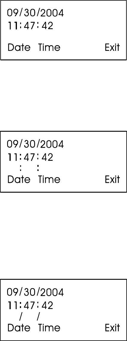
E-8 / Appendix E - Display/5x5Keypad CI-ControlWave Express
The current time is shown in the form of hours:minutes:seconds.
Figure 8 - Clock Display
E4.1.3.1 Changing the Time
From the display shown in Figure 8, press Time [F2]. Colons (:) will appear on the third
line. Enter the new time there and press [ENTER]. Valid times range from 00:00:00 to
23:59:59. Invalid entries will be ignored. The display will be updated to show the new time.
Figure 9 - Time Set Display
If you make a mistake while entering the new time, use [DEL] to backspace and delete one
character at a time.
E4.1.3.2 Changing the Date
From the clock display (Figure 8, press [F1]. Slash marks (/) will appear on the third line.
Enter the new date there and press [ENTER].
Figure 10 - Date Set Display
If you make a mistake while entering the new date, use [DEL] to back space and delete one
character at a time. Press [F4] to return to the Logged-On Display (Figure 7C).
Click here to return to Table of Contents
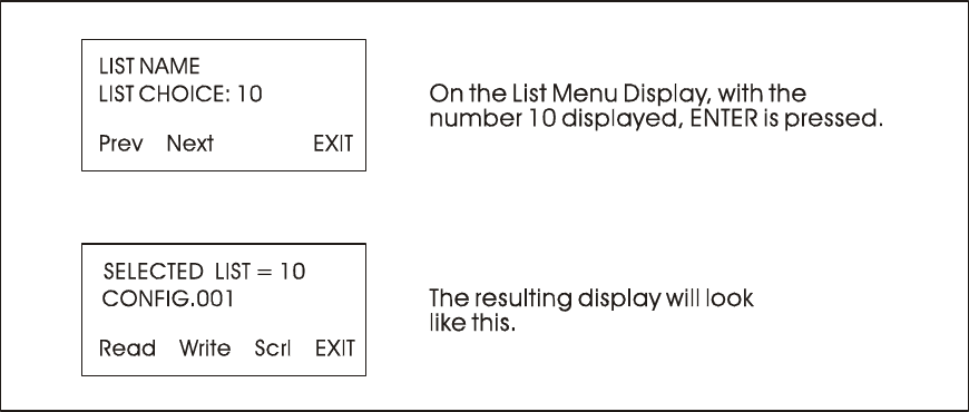
CI-ControlWave Express Appendix E - Display/Keypad / E-9
E4.1.4 Choosing a Variable List from the List Menu
The List Menu is another area where variable information can be seen. As explained earlier
in this section, your first opportunity to read variable information is by choosing the
SCROLL function from the Initial Display. The variable name and value are presented
from the Scroll List. This function is available to all users even without signing-on.
The List Menu will show other groups of variable which you can choose to read. This in-
formation will be more detailed than the Scroll List.
To get to the List Menu, choose MENU (press [F2]) from the Logged-On Display (Figure
7C).
Figure 11 - Using the List Menu Display
The first variable list number in the menu will appear on the second line.
Press PREV (F1) and NEXT (F2) to see the other variable lists that are available in the List
Menu. You can also use the Up and Down Arrow Keys to scroll through the various lists. To
move directly to a list, enter the list number, then press [ENTER].
E4.1.5 Moving Through a Variable List
After READ (F1) or WRITE (F2) has been pressed, the display will show the first variable
in the list. An example is shown in Figure 12. Each time NEXT (F2) is pressed; the display
will show the next variable in the list. PREV (F1) will show the previous variable. You can
also use the Up and Down Arrow Keys to move through a list.
Automatic wraparound occurs in either direction. When you reach the end of the list, [F1]
will display the first variable again. At the top of the list, [F2] will display the last variable.
E4.1.6 Changing Variable Parameters
From Figure 11, you can change variable parameters by pressing F2 [Write]. Then follow
the directions summarized below (see Note 2).
Note 2: If your display does not contain the legend Write in the legend line, your password
will only allow you to read variables. If you want to change variable values at this
Click here to return to Table of Contents
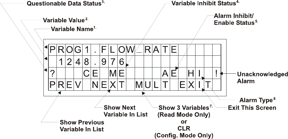
E-10 / Appendix E - Display/5x5Keypad CI-ControlWave Express
time, you must first log-off and then log-on using the correct password. See your
Systems Engineer for the correct password.
Before making any changes, first check the signal inhibit status field (See Figure 12). When
the display shows ME (manual enable) you can change variable parameters. When it shows
MI (manual inhibit), you cannot alter the parameters of this variable. If the field indicates
MI, press the OPER I/E key to change it to ME.
To change an analog value:
Press CHNG (F3) to clear the third line. Use the number keys 0 through 9 to enter the
new value. The minus sign and period are also permitted. Press [ENTER].
If you make a mistake, press CHNG (F3) and enter the number again or use the [DEL]
key to erase a character.
Another way to enter new values is by using the arrow up and arrow down keys (located
below the [F3] key and left of the [INIT] key). These keys will raise and lower the value
by 1% of the displayed amount.
To change the status of a logical variable:
Press CHNG (F3), then use either the down and up arrow keys or the [0/OFF] and
[1/ON] keys to change the state of a logical variable. If the [0/OFF] and [1/ON] keys are
used, you must also press [ENTER].
Figure 12 - Interpreting Variable Information
To acknowledge an alarm:
Press [ALM ACK].
To change the alarm enable/inhibit status for alarm variables:
Press [ALM I/E] key. (Note: This will only inhibit alarm reporting, and not alarm level
detection.)
Click here to return to Table of Contents

CI-ControlWave Express Appendix E - Display/Keypad / E-11
Notes for Figure 12
1. Variable Name (Example 1: @GV.FLOW_RATE) (Example 2: @GV.TOTAL_FLOW_RATE)
2. Value - analog value, string value, or logical value. Values which cannot fit in this field will be
shown as asterisks.
Analog values are displayed in floating point format, for example, 0.0125, 99.627, and 1287.66.
When the value cannot be shown in floating point format, scientific format is used
(1.287668E+10 or 1.25E-02 for example).
3. Questionable Data Status - for analog variables, column 1 will be clear if the status is valid. It
will display a question mark if the status is questionable.
4. Variable Inhibit Status
CE (Control Enable) means this variable can be updated by the ControlWave project.
CI (Control Inhibit) means the variable cannot be updated by the ControlWave project.
ME (Manual Enable) means the variable can be changed manually.
MI (Manual Inhibit) means the variable cannot be changed manually.
5. Alarm Enable (for alarm variables only)
AE - variable is alarm enabled (changes will be reported).
AI - variable is alarm inhibited (changes will not be reported).
6. Alarm State
For Analog Variables: For Logical Variables:
HH - high-high alarm TA - true alarm
HI - high alarm FA - false alarm
LO - low alarm CA - change-of-state alarm
LL - low-low alarm
! - alarm is unacknowledged
Notes for Figure 12 (Continued)
7 Multiple Signal Display
In Read Mode, pressing MULT (F3) will display the variable name extension, value, and units
for three variables at one time. These variables include the variable displayed when NEXT (F2)
was pressed and the next two variables in the list. Press SNGL [F3] to return to viewing one
variable at a time (see Figure 12A).
Figure 12A - Example of MULT Display in READ Mode
Variables are shown below as they would appear in SNGL mode.
Click here to return to Table of Contents

E-12 / Appendix E - Display/5x5Keypad CI-ControlWave Express
1) String
SITE_NAME
WEST SUNBURY PUMP STATION
CE ME
2) Analog
TOTAL_FLOW_RATE
1260.578
CE MI
3) Logical
FLOW_ALARM
OFF
CE MI AE NA
E4.1.7 Signing-Off
Once you have logged-on, use the [INIT] key at any time to log-off. When this key has been
pressed, the screen will look like Figure 13. Press Yes (F1) to sign-off. You are signed-off
when the Identifier Display (Figure 3C) appears.
If you do not want to log-off, press Exit (F4) to leave the Log-Off Display.
Once you are signed-on an automatic sign-off will occur if 20 minutes has elapsed since the
last key was pressed.
Figure 13 - Log-Off Display
Click here to return to Table of Contents
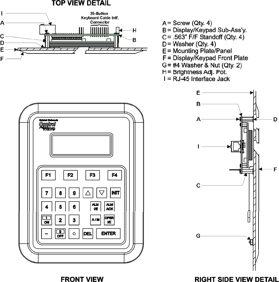
CI-ControlWave Express Appendix E - Display/Keypad / E-13
E5.1 KEYPAD IDENTIFICATION & INSTALLATION INFO.
Figure 14 - 25-Button Display/Keypad Assembly Installation Drawing
Click here to return to Table of Contents
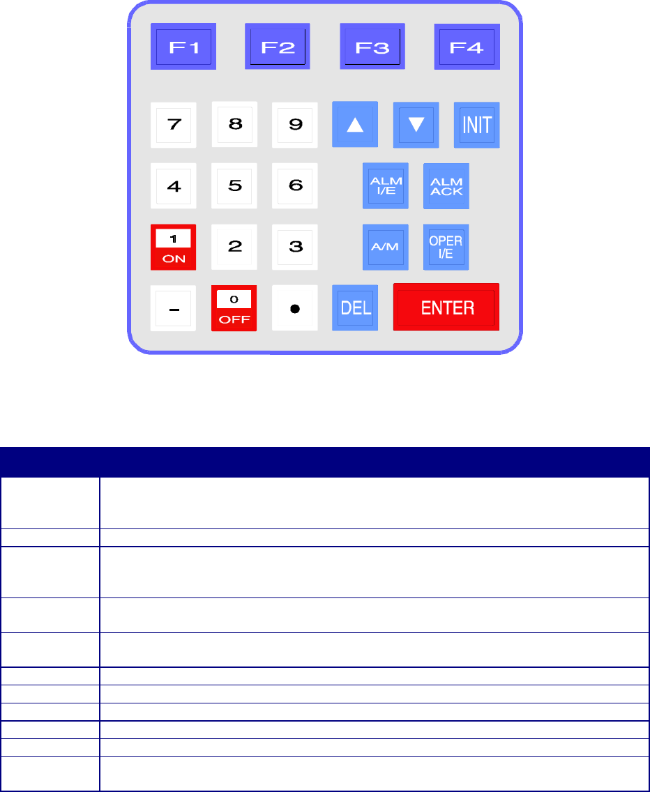
E-14 / Appendix E - Display/5x5Keypad CI-ControlWave Express
Figure 15 - 25 Button Keypad
Table 1 - 25 Button Keypad Keys
KEY
FUNCTION
F1, F2, F3,
F4
Function keys will take on a variety of different functions depending on the
situation. The function of these keys is listed on the legend line (bottom line) of the
display.
INIT The INIT key is used to terminate the keyboard session and sign-off.
0 to 9, -, .
These keys are used to change the value of analog variables in the
CONFIGURATION mode. The 0/OFF and 1/ON keys are used to change the state
of logical variables.
Δ Each press of this key will raise an analog variable value by 1% of the displayed
value or turn a logical variable ON.
∇ Each press of this key will lower an analog variable value by 1% of the displayed
value or turn a logical variable OFF.
ALM I/E Use this key to enable or inhibit alarm variables.
ALM ACK Use this key to acknowledge alarms.
A/M Toggle between AUTO (CE) and MANUAL (CI) with this key.
OPER I/E Toggle between manual inhibit (MI) and enable (ME) with this key.
DEL Use this backspace key to erase digits that have been entered on the keypad.
ENTER This key is used to enter new data from the display into the controller, e.g.,
password or variable values.
Click here to return to Table of Contents

02/4/09 Appendix Z - CI-ControlWave Express MSDS
Sources for Obtaining
Material Safety Data Sheets
This device includes certain components or materials which may be hazardous if misused.
For details on these hazards, please contact the manufacturer for the most recent material
safety data sheet.
Manufacturer General Description Part Number
DURACELL
http://www.duracell.com
3V Lithium Manganese
Dioxide Battery DL 2450
Bristol Battery Part Number = 395620-01-5
Click here to return to Table of Contents
BLANK PAGE
Click here to return to Table of Contents
SITE CONSIDERATIONS
For
EQUIPMENT INSTALLATION,
GROUNDING
&
WIRING
Bristol Babcock
Supplement Guide - S1400CW
Issue: 04/05
A Guide for the Protection of
Site Equipment & Personnel
In the Installation of
ControlWave
Process Automation Controllers
TM
Click here to return to Table of Contents

NOTICE
Copyright Notice
The information in this document is subject to change without notice. Every effort has been
made to supply complete and accurate information. However, Bristol Babcock assumes no
responsibility for any errors that may appear in this document.
Request for Additional Instructions
Additional copies of instruction manuals may be ordered from the address below per
attention of the Sales Order Processing Department. List the instruction book numbers or
give complete model number, serial or software version number. Furnish a return address
that includes the name of the person who will receive the material. Billing for extra copies
will be according to current pricing schedules.
ControlWave® is a re registered trademark of Bristol Babcock. Other trademarks or copy-
righted products mentioned in this document are for information only, and belong to their
respective companies, or trademark holders.
Copyright (c) 2005 Bristol Babcock, 1100 Buckingham St., Watertown, CT 06795. No part of
this manual may be reproduced in any form without the express written permission of
Bristol Babcock.
Click here to return to Table of Contents

Supplement S1400CW Page 0-1 Table Of Contents
Supplement Guide S1400CW
SITE CONSIDERATIONS FOR EQUIPMENT
INSTALLATION, GROUNDING & WIRING
TABLE OF CONTENTS
SECTION TITLE PAGE #
Section 1 - INTRODUCTION
1.1 GENERAL INTRODUCTION .......................................................................................1-1
1.2 MAJOR TOPICS............................................................................................................. 1-1
Section 2 - PROTECTION
2.1 PROTECTING INSTRUMENT SYSTEMS................................................................... 2-1
2.1.1 Quality Is Conformance To Requirements.................................................................... 2-1
2.2 PROTECTING EQUIPMENT & PERSONNEL ...........................................................2-1
2.2.1 Considerations For The Protection of Personnel ..........................................................2-2
2.2.2 Considerations For The Protection of Equipment ........................................................ 2-2
2.3 OTHER SITE SAFETY CONSIDERATIONS............................................................... 2-3
Section 3 - GROUNDING & ISOLATION
3.1 POWER & GROUND SYSTEMS................................................................................... 3-1
3.2 IMPORTANCE OF GOOD GROUNDS......................................................................... 3-1
3.3 EARTH GROUND CONNECTIONS............................................................................. 3-1
3.3.1 Establishing a Good Earth Ground. .............................................................................. 3-1
3.3.1.1 Soil Conditions ................................................................................................................ 3-2
3.3.1.2 Soil Types ........................................................................................................................ 3-2
3.3.1.3 Dry, Sandy or Rocky Soil................................................................................................3-4
3.3.2 Ground Wire Considerations. ........................................................................................ 3-5
3.3.3 Other Grounding Considerations. ................................................................................. 3-6
3.4 ISOLATING EQUIPMENT FROM THE PIPELINE ................................................... 3-7
3.4.1 Meter Runs Without Cathodic Protection.....................................................................3-7
3.4.2 Meter Runs With Cathodic Protection .......................................................................... 3-7
Section 4 - LIGHTNING ARRESTERS & SURGE PROTECTORS
4.1 STROKES & STRIKES .................................................................................................. 4-1
4.1.1 Chance of Being Struck by Lightning. .......................................................................... 4-1
4.1.2 Antenna Caution ............................................................................................................4-3
4.1.3 Ground Propagation ....................................................................................................... 4-5
4.1.4 Tying it all Together .......................................................................................................4-5
4.1.5 Impulse Protection Summary ........................................................................................ 4-5
4.2 USE OF LIGHTNING ARRESTERS & SURGE PROTECTORS................................ 4-6
Section 5 - WIRING TECHNIQUES
5.1 OVERVIEW ....................................................................................................................5-1
5.2 INSTRUMENT WIRING. ..............................................................................................5-1
5.2.1 Common Returns............................................................................................................5-1
Click here to return to Table of Contents

Supplement S1400CW Page 0-2 Table Of Contents
Supplement Guide S1400CW
SITE CONSIDERATIONS FOR EQUIPMENT
INSTALLATION, GROUNDING & WIRING
TABLE OF CONTENTS
SECTION TITLE PAGE #
Section 5 - WIRING TECHNIQUES (Continued)
5.2.2 Use of Twisted Shielded Pair Wiring (with Overall Insulation).................................. 5-2
5.2.3 Grounding of Cable Shields. .......................................................................................... 5-3
5.2.4 Use of Known Good Earth Grounds .............................................................................. 5-3
5.2.5 Earth Ground Wires .......................................................................................................5-3
5.2.6 Working Neatly & Professionally .................................................................................. 5-3
5.2.7 High Power Conductors and Signal Wiring .................................................................. 5-4
5.2.8 Use of Proper Wire Size ................................................................................................. 5-4
5.2.9 Lightning Arresters & Surge Protectors ....................................................................... 5-4
5.2.10 Secure Wiring Connections............................................................................................5-5
REFERENCE DOCUMENTS
1. IEEE Recommended Practice for Grounding of Industrial and Commercial Power Systems - ANSI/IEEE Std
142-1982
2. IEEE Guide for the Installation of Electrical Equipment to Minimize Electrical Noise inputs to Controllers
from External Sources - IEE Std 518-1982
3. Lightning Strike Protect; Roy B. Carpenter, Jr. & Mark N. Drabkin, Ph.D.; Lightning Eliminators &
Consultant, Inc., 6687 Arapahoe Road, Boulder Colorado
4. Lightning Protection Manual for Rural Electric Systems, NRECA Research Project 82-5, Washington DC,
1983
5. Grounding for the Control of EMI; Hugh W. Denny; Don White Consultants, Inc., 1983, 1st Edition
6. Fundamentals of EGM - Electrical Installations; Michael D. Price; NorAm Gas Transmission, 525 Milam
Street, Shreveport, Louisiana 71151
7. TeleFlow Modem Grounding Kit 621495-01-8 Installation Instructions - PIP-3530MGKI; Bristol Babcock,
Watertown, CT 06795
Click here to return to Table of Contents

Section 1 - Overview Page 1-1 S1400CW
Section 1 - Overview
1.1 INTRODUCTION
This document provides information pertaining to the installation of ControlWave
systems; more specifically, information covering reasons, theory and techniques for
protecting your personnel and equipment from electrical damage. Your instrument system
affects the quality of service provided by your company and many aspects of its operational
safety. Loss of instruments means lost production and profits as well as increased expenses.
Information contained in this document is for educational purposes. Bristol Babcock makes
no warranties or guarantees on the effectiveness or the safety of techniques described herein.
Where the safety of installations and personnel is concerned, refer to the National Electrical
Code Rules and rules of local regulatory agencies.
1.2 MAJOR TOPICS
Topics are covered in seven sections designed to pinpoint major areas of concern for the
protection of site equipment and personnel. The following overview is provided for each of
the major sections.
·Section 2 - Protection
This section provides the reasons for protecting instrument systems. An overview of the
definition of quality and what we are trying to accomplish in the protection of site
installations and how to satisfy the defined requirements is presented. Additionally,
this section provides considerations for the protection of personnel and equipment.
·Section 3 - Grounding & Isolation
Information pertaining to what constitutes a good earth ground, how to test and
establish such grounds, as well as when and how to connect equipment to earth grounds
is provided
·Section 4 - Lightning Arresters & Surge Protectors
Some interesting information dealing with Lightning strikes and strokes is presented in
technical and statistical form along with a discussion of how to determine the likelihood
of a lightning strike. Protecting equipment and personnel during the installation of
radios and antenna is discussed in a review of the dangers to equipment and personnel
when working with antennas. Reasons for the use of lightning arresters and surge
protectors are presented along with overviews of how each device protects site
equipment.
·Section 5 - Wiring Techniques
Installation of Power and “Measurement & Control” wiring is discussed. Information on
obscure problems, circulating ground and power loops, bad relays, etc. is presented.
Good wire preparation and connection techniques along with problems to avoid are
discussed. This sections list the ten rules of instrument wiring.
Click here to return to Table of Contents

Section 2 - Protection Page 2-1 S1400CW
Section 2 - Protection
2.1 PROTECTING INSTRUMENT SYSTEMS
Electrical instrumentation is susceptible to damage from a variety of natural and man
made phenomena. In addition to wind, rain and fire, the most common types of system and
equipment damaging phenomena are lightning, power faults, communication surges &
noise and other electrical interference’s caused by devices such as radios, welders,
switching gear, automobiles, etc. Additionally there are problems induced by geophysical
electrical potential & noise plus things that are often beyond our wildest imagination.
2.1.1 Quality Is Conformance To Requirements
A quality instrumentation system is one that works reliably, safely and as purported by the
equipment manufacturer (and in some cases by the system integrator) as a result of good
equipment design and well defined and followed installation practices. If we except the
general definition of quality to be, “quality is conformance to requirements,” we must also
except the premise that a condition of “quality” can’t exist where requirements for such an
end have not been evolved. In other words, you can’t have quality unless you have
requirements that have been followed. By understanding the requirements for a safe, sound
and reliable instrumentation system, and by following good installation practices (as
associated with the personnel and equipment in question), the operational integrity of the
equipment and system will be enhanced.
Understanding what is required to properly install BBI equipment in various en-
vironments, safely, and in accordance with good grounding, isolating and equipment
protection practices goes a long way toward maintaining a system which is healthy to the
owner and customer alike. Properly installed equipment is easier to maintain and operate,
and is more efficient and as such more profitable to our customers. Following good in-
stallation practices will minimize injury, equipment failure and the customer frustrations
that accompany failing and poorly operating equipment (of even the finest design). Ad-
ditionally, personnel involved in the installation of a piece of equipment add to or subtract
from the reliability of a system by a degree which is commensurate with their technical
prowess, i.e., their understanding of the equipment, site conditions and the requirements
for a quality installation.
2.2 PROTECTING EQUIPMENT & PERSONNEL
ControlWave installations must be performed in accordance with National Electrical Code
Rules, electrical rules set by local regulatory agencies, and depending on the customer
environment (gas, water, etc), other national, state and local agencies such as the American
Water Works Association (AWWA). Additionally, installation at various customer sites may
be performed in conjunction with a “safety manager” or utility personnel with HAZMAT
(hazardous material) training on materials present (or potentially present) as required by
OSHA, the customer, etc.
Click here to return to Table of Contents

S1400CW Page 2-2 Section 2 - Protection
2.2.1 Considerations For The Protection of Personnel
Always evaluate the site environment as if your life depended on it. Make sure that you
understand the physical nature of the location where you will be working. Table 2-1
provides a general guideline for evaluating an installation site.
Table 2-1 - Installation Site Safety Evaluation Guide
# Guide
1 Indoor or outdoor – Dress Appropriately
2 If outdoor, what kind of environment, terrain, etc. Watch out for local varmint (bees,
spiders, snakes, etc.)
3 If indoor or outdoor – determine if there are any pieces of dangerous equipment or any
processes which might be a risk to your safety
4 If in a tunnel, bunker, etc. watch out for a build up of toxic or flammable gases. Make
sure the air is good. Watch out for local varmint (bees, spiders, snakes, etc.)
5 Hazardous or Non-Hazardous Environment – Wear appropriate safety equipment and
perform all necessary safety measures.
6 Before installing any equipment or power or ground wiring, make sure that there are no
lethal (life threatening) voltages between the site where the instrument will be installed
and other equipment, pipes, cabinets, etc. or to earth itself.
7 Never assume that adjacent or peripheral equipment has been properly installed and
grounded. Determine if this equipment and the ControlWave unit in question can be
touched simultaneously without hazard to personnel and/or equipment?
8 Before embarking to remote locations where there are few or no human inhabitants ask a
few simple questions like, should I bring water, food, hygienic materials, first aid kit, etc?
Be Prepared!
9 Observe the work habits of those around you – for your own safety!
Some of the items that a service person should consider before ever going on site can be
ascertained by simply asking questions of the appropriate individual. Obviously other
safety considerations can only be established at the installation site.
2.2.2 Considerations For The Protection of Equipment
Always evaluate the site installation/service environment and equipment. Understand the
various physical interfaces you will be dealing with such as equipment mounting and
supporting, ControlWave analog and digital circuits, power circuits, communication
circuits and various electrical grounds. Table 2-2 provides a general guideline for
evaluating the equipment protection requirements of an installation site.
Table 2-2 - Equipment Protection Site Safety Evaluation Guide
# Guide Reference Section
1 Environment - Class I, Division 2 - Nonincendive
Environment - Class I, Division 1 - Intrinsically Safe
Other - Safe or unrated area
See Appendix A of CI Manual
See Appendix B of CI Manual
2 Earth Ground - Established by mechanical/electrical or
(both) or not at all.
See Section 3
3 Is the area prone to lightning strikes? See Section 4
4 Are there surge suppressors installed or to be installed? See Section 4
5 Are there overhead or underground power or com-
munication cables in the immediate area?
See Section 2.3
Click here to return to Table of Contents

Section 2 - Protection Page 2-3 S1400CW
Table 2-2 - Equipment Protection Site Safety Evaluation Guide (Continued)
# Guide Reference Section
6 Is there an antenna in the immediate area? See Section 4.1.2
7 How close is other equipment? Can someone safely touch this
equipment and a ControlWave simultaneously?
See Section 2.3
8 Determine equipment ground requirements. How will the
ControlWave and its related wiring be grounded? Consider Earth
Ground, Circuit Ground, Conduit Ground, Site Grounds!
See Section 3
9 Are there any obviously faulty or questionable power or ground
circuits?
See Section 2.3
2.3 OTHER SITE SAFETY CONSIDERATIONS
Overhead or underground power or communication cables must be identified prior to
installing a new unit. Accidentally cutting, shorting or simply just contacting power,
ground, communication or process control I/O wiring can have potentially devastating
effects on site equipment, the process system and or personnel.
Don’t assume that it is safe to touch adjacent equipment, machinery, pipes, cabinets or even
the earth itself. Adjacent equipment may not have been properly wired or grounded, may be
defective or may have one or more loose system grounds. Measure between the case of a
questionable piece of equipment and its earth ground for voltage. If a voltage is present,
something is wrong.
AC powered equipment with a conductive case should have the case grounded. If you don’t
see a chassis ground wire, don’t assume that it is safe to touch this equipment. If you notice
that equipment has been grounded to pipes, conduit, structural steel, etc., you should be
leery. Note: AWWA’s policy on grounding of electric circuits on water pipes states,
“The American Water Works Association (AWWA) opposes the grounding of
electrical systems to pipe systems conveying water to the customer’s premises….”
Be sure that the voltage between any two points in the instrument system is less than the
stand-off voltage. Exceeding the stand-off voltage will cause damage to the instrument and
will cause the instrument to fail.
Click here to return to Table of Contents

Section 3 - Grounding & Isolation Page 3-1 S1400CW
Section 3 - Grounding & Isolation
3.1 POWER & GROUND SYSTEMS
ControlWaves utilize DC power systems. AC power supplies are not provided with Con-
trolWave units. ControlWave, ControlWave MICRO, ControlWave EFM/GFC/EFC,
ControlWaveRED, ControlWaveREDIO and ControlWave I/O Expansion Racks are
provided with a Ground Lug that accommodates up to a #4 AWG size wire for establishing
a connection to Earth Ground. In the case of the ControlWaveLP, a Chassis Ground
termination terminal (TB2, Pin-3), that accepts up to a #14 AWG size wire, is provided on
the unit’s Power Supply/Sequencer Board.
3.2 IMPORTANCE OF GOOD GROUNDS
ControlWave units (see above) are utilized in instrument and control systems that must
operate continually and within their stated accuracy over long periods of time with
minimum attention. Failures resulting from an improperly grounded system can become
costly in terms of lost time and disrupted processes. A properly grounded system will help
prevent electrical shock hazards resulting from contact with live metal surfaces, provide
additional protection of equipment from lightning strikes and power surges, minimize the
effects of electrical noise and power transients, and reduce signal errors caused by ground
wiring loops. Conversely, an improperly grounded system may exhibit a host of problems
that appear to have no relation-ship to grounding. It is essential that the reader (service
technician) have a good under-standing of this subject to prevent needless troubleshooting
procedures.
WARNING
This device must be installed in accordance with the National
Electrical Code (NEC) ANSI/NEPA-70. Installation in hazardous
locations must also comply with Article 500 of the code. For
information on the usage of ControlWave units in Class I, Division 2,
Groups C & D Hazardous and Nonhazardous locations, see appendix A
of the applicable Customer Instruction (CI) manual. For information
on the usage of ControlWave units in Class I, Division 1, Groups C &
D Hazardous locations, see appendix B of the applicable Customer
Instruction (CI) manual.
3.3 EARTH GROUND CONNECTIONS
To properly ground a ControlWave unit, the units Chassis Ground (post or terminal) must
ultimately be connected to a known good Earth Ground. Observe recommendations
provided in topics Establishing a Good Earth Ground and Ground Wire Considerations.
3.3.1 Establishing a Good Earth Ground
A common misconception of a ground is that it consists of nothing more than a metal pipe
driven into the soil. While such a ground may function for some applications, it will often
Click here to return to Table of Contents
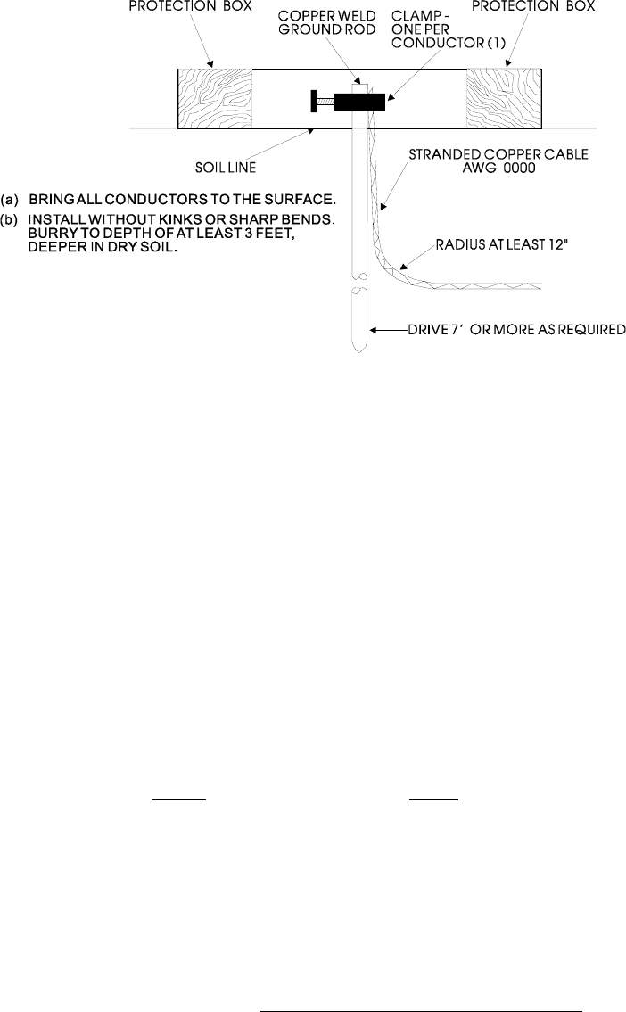
S1400CW Page 3-2 Section 3 - Grounding & Isolation
not be suitable for a complex system of sophisticated electronic equipment. Conditions such
as soil type, composition and moisture will all have a bearing on ground reliability.
A basic ground consists of a 3/4-inch diameter rod with a minimum 8-foot length driven into
conductive earth to a depth of about 7-feet as shown in Figure 3-1. Number 3 or 4 AWG
solid copper wire should be used for the ground wire. The end of the wire should be clean,
free of any coating and fastened to the rod with a clamp. This ground connection should be
covered or coated to protect it from the weather and the environment.
Figure 3-1 - Basic Ground Rod Installation
3.3.1.1 Soil Conditions
Before installing a ground rod, the soil type and moisture content should be analyzed.
Ideally, the soil should be moist and moderately packed throughout to the depth of the
ground rod. However, some soils will exhibit less than ideal conditions and will require
extra attention.
Soil types can be placed into two general categories with respect to establishing and
maintaining a good earth ground, i.e., ‘Good Soil’ and ‘Poor Soil.’
To be a good conductor, soil must contain some moisture and free ions (from salts in the
soil). In very rainy areas, the salts may be washed out of the soil. In very sandy or arid area
the soil may be to dry and/or salt free to a good conductor. If salt is lacking add rock salt
(NaCl); if the soil is dry add calcium chloride (CaCl2).
3.3.1.2 Soil Types: Good Poor
Damp Loam Back Fill
Salty Soil or Sand Dry Soil
Farm Land Sand Washed by a Lot of Rain
Dry Sand (Desert)
Rocky Soil
Ground Beds must always be tested for conductivity prior to being placed into service. A
brief description of ground bed testing in ‘Good Soil’ and ‘Poor Soil’ is provided herein.
Details on this test are described in the National Electrical Code Handbook. Once a reliable
Click here to return to Table of Contents
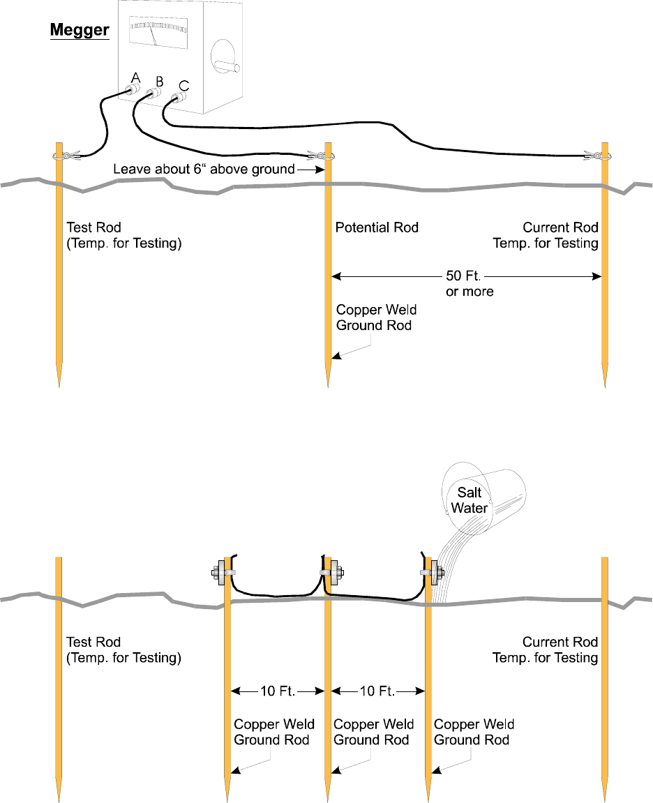
Section 3 - Grounding & Isolation Page 3-3 S1400CW
ground has been established, it should be tested on a regular basis to preserve system
integrity.
Figure 3-2 - Basic Ground Bed Soil Test Setup
Figure 3-3 - Basic Ground Bed Soil Test Setup with Additional Ground Rods
Figure 3-2 shows the test setup for ‘Good Soil’ conditions. If the Megger* reads less than 5
ohms, the ground is good. The lower the resistance, the better the earth ground. If the
Click here to return to Table of Contents
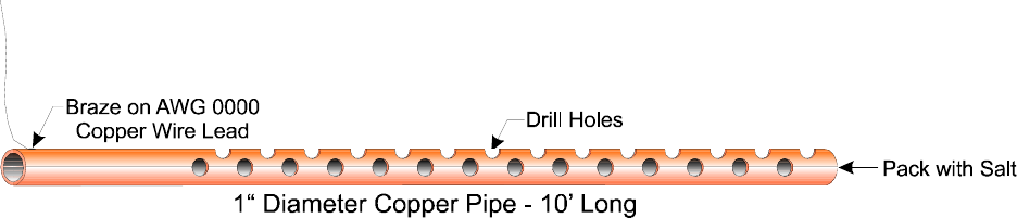
S1400CW Page 3-4 Section 3 - Grounding & Isolation
Megger reads more than 10 ohms, the ground is considered ‘poor.’ If a poor ground is
indicated, one or more additional ground rods connected 10 feet from the main ground rod
should be driven into the soil and interconnected via bare AWG 0000 copper wire and 1” x
¼-20 cable clamps as illustrated in Figure 3-3). * Note: Megger is a Trademark of the
Biddle Instrument Co. (now owned by AVO International). Other devices that
may be used to test ground resistance are “Viboground”; Associated Research,
Inc., “Groundmeter”; Industrial Instruments, Inc., and “Ground-ohmer”; Herman
H. Sticht Co., Inc.
If the Megger still reads more than 10 ohms, mix a generous amount of cooking salt, ice
cream salt or rock salt with water and then pour about 2.5 to 5 gallons of this solution
around each rod (including the test rods). Wait 15 minutes and re-test the soil. If the test
fails, the soil is poor and a ‘Poor Soil Ground Bed’ will have to be constructed.
Figure 3-4 shows a typical Poor Soil Ground Bed Electrode. A Poor Soil Ground Bed will
typically consists of four or more 10-foot long electrodes stacked vertically and separated by
earth. Figure 3-5 shows the construction of a Poor Soil Ground Bed. For some poor soil
sites, the ground bed will be constructed of many layers of ‘Capacitive Couplings’ as
illustrated. In extremely poor soil sites one or more 3’ by 3’ copper plates (12 gauge or 1/16”
thick) will have to be buried in place of the electrodes.
Figure 3-4 - Ground Electrode Construction for Poor Soil Conditions
3.3.1.3 Dry, Sandy or Rocky Soil
Very dry soil will not provide enough free ions for good conductance and a single ground rod
will not be effective. A buried counterpoise or copper screen is recommended for these
situations. It will be necessary to keep the soil moist through regular applications of water.
Sandy soil, either wet or dry, may have had its soluble salts leached out by rain water,
thereby reducing conductivity of the ground. High currents from lightning strikes could also
melt sand and cause glass to form around the ground rod, rendering it ineffective. A buried
counterpoise or copper screen is preferred for these installations along with regular
applications of salt water.
Rocky soil can pose many grounding problems. A counterpoise or copper plate will probably
be required. Constructing a trench at the grounding site and mixing the fill with a
hygroscopic salt such as calcium chloride may help for a time. Soaking the trench with
water on a regular basis will maintain conductivity.
Units with phone modems require the use of a lightning arrester. The lightning arrester
must be situated at the point where the communication line enters the building.
Click here to return to Table of Contents
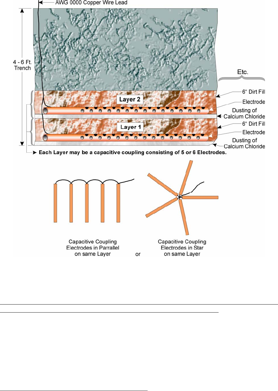
Section 3 - Grounding & Isolation Page 3-5 S1400CW
Figure 3-5 - Poor Soil Ground Bed Construction Diagram
3.3.2 Ground Wire Considerations
ControlWave, ControlWave MICRO, ControlWave EFM/GFC/XFC, Control-
WaveRED, ControlWave REDIO & ControlWave I/O Expansion Rack
ControlWave Chassis are provided with a Ground Lug that accommodates up to a #4 AWG
wire size. A ground wire must be run between the Chassis Ground Lug and a known good
Earth Ground. The cases of the various ControlWave Modules are connected to Chassis
Ground when they have been installed and secured via their two Captured Panel
Fasteners. As an extra added precaution, it is recommended that a #14 AWG wire be run
from PSSM Power Connector TB2-5 (Chassis Ground) (PSSM Connector TB1-3 for
ControlWave MICRO unit) (SCM Connector TB1-3 for ControlWave EFM) to the same
known good Earth Ground.
ControlWaveLP Process Automation Controller
A #14 AWG ground wire must be run from the ControlWaveLP’s PSSB Terminal TB2-3
(Chassis Ground) to a known good Earth Ground. In lieu of a direct connection to Earth
Click here to return to Table of Contents
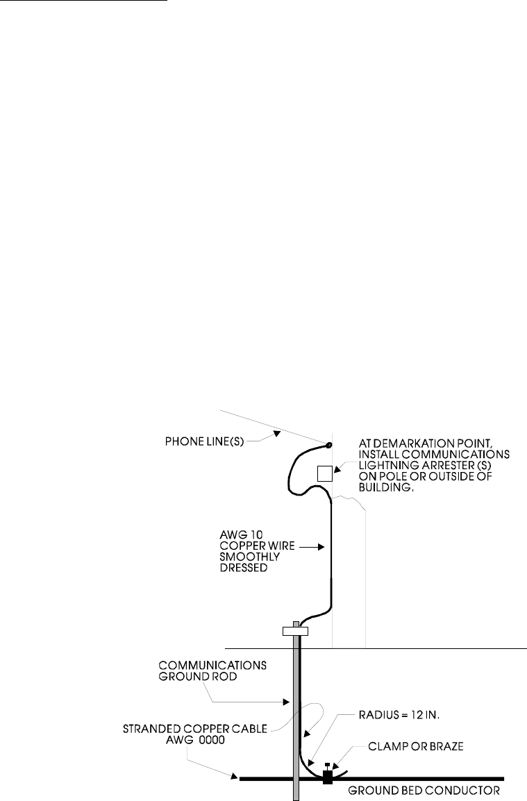
S1400CW Page 3-6 Section 3 - Grounding & Isolation
Ground, it is recommended that the unit’s Chassis Ground Terminal be connected to a
conductive mounting panel or plate, a user supplied Ground Lug or a user supplied Ground
Bus. The panel, lug or bus in turn must be connected to a known good Earth Ground via a
#4 AWG wire.
General Considerations
The following considerations are provided for the installation of ControlWave system
grounds:
i Size of ground wire (running to Earth Ground should be #4 AWG. It is recommended
that stranded copper wire is used for this application and that the length should be as
short as possible.
i This ground wire should be clamped or brazed to the Ground Bed Conductor (that is
typically a stranded copper AWG 0000 cable installed vertically or horizontally).
i The wire ends should be tinned with solder prior to installation.
i The ground wire should be run such that any routing bend in the cable has a
minimum radius of 12-inches below ground and 8-inches above ground.
The units Earth Ground Cable should be clamped to an exposed Ground Rod or to an AWG
0000 stranded copper Ground Cable that in turn should be connected to either an Earth
Ground Rod or Earth Ground Bed. Both ends of the units Earth Ground Cable must be free
of any coating such as paint or insulated covering as well as any oxidation. The connecting
point of the Ground Rod or AWG 0000 Ground Cable must also be free of any coating and
free of oxidation. Once the ground connection has been established (at either the Ground
Rod or Ground Cable) it should be covered or coated to protect it from the environment.
3.3.3 Other Grounding Considerations
Figure 3-6 - Grounding of Phone Line
Click here to return to Table of Contents

Section 3 - Grounding & Isolation Page 3-7 S1400CW
For applications employing equipment that communicates over telephone lines, a lightning
arrester Must Be provided. For indoor equipment the lightning arrester must be installed
at the point where the communication line enters the building as shown in Figure 3-6. The
ground terminal of this arrester must connect to a ground rod and/or a buried ground bed.
Gas lines also require special grounding considerations. If a gas meter run includes a
thermocouple or RTD sensor installed in a thermowell, the well (not the sensor) must be
connected to a gas discharge-type lightning arrester as shown in Figure 3-7. A copper braid,
brazed to the thermal well, is dressed into a smooth curve and connected to the arrester as
shown. The curve is necessary to minimize arcing caused by lightning strikes or high static
surges. The path from the lightning arrester to the ground bed should also be smooth and
free from sharp bends for the same reason.
Figure 3-7 - Grounding of Thermometer Well in Gas Line
3.4 ISOLATING EQUIPMENT FROM THE PIPELINE
3.4.1 Meter Runs Without Cathodic Protection
ControlWave EFM/GFC/XFC’s may be mounted directly on the pipeline or remotely on a
vertical stand-alone two-inch pipe (see Figure 3-8). The Earth Ground Cable is to run
between the ControlWave EFM/GFC/XFC’s Ground Lug and Earth Ground (Rod or Bed)
even though the ControlWave EFM/GFC/XFC’s Multivariable Transducer may be
Click here to return to Table of Contents
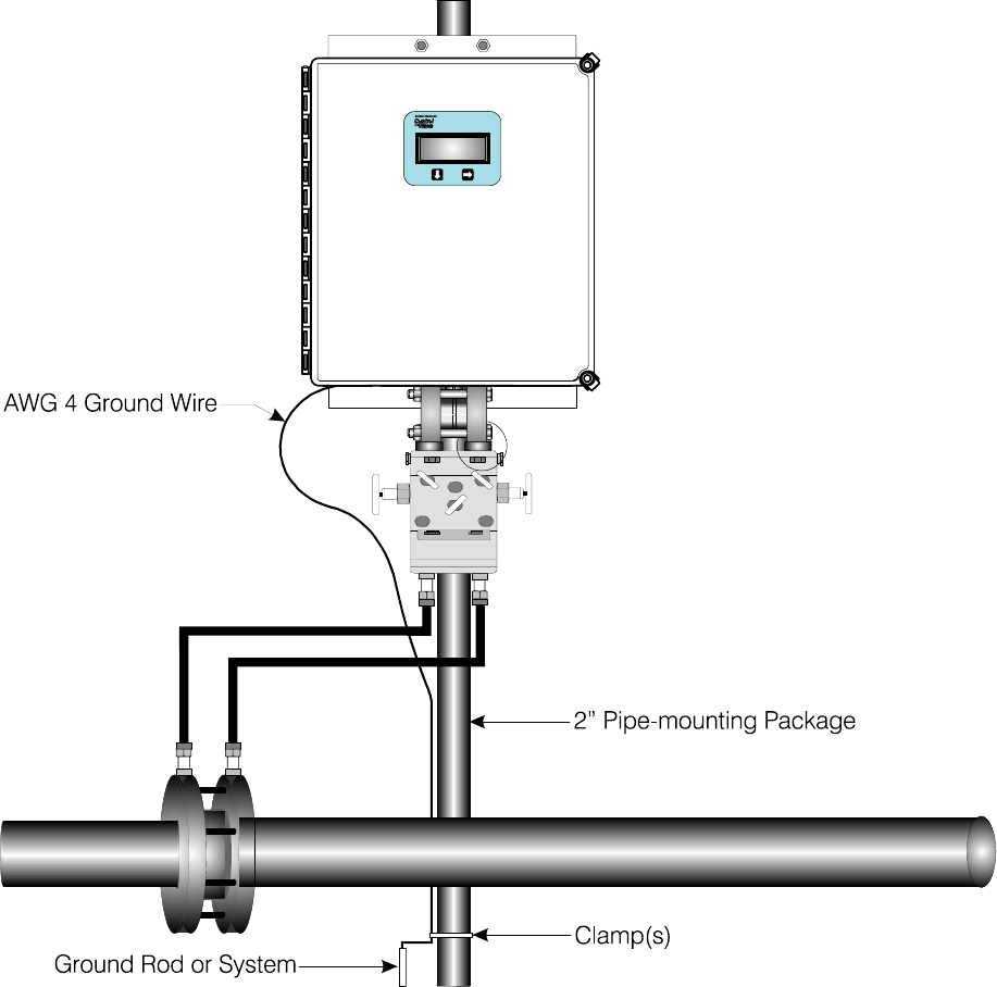
S1400CW Page 3-8 Section 3 - Grounding & Isolation
grounded to the pipeline. If any pressure transmitters or pulse transducers are remotely
mounted, connect their chassis grounds to the pipeline or earth ground.
Figure 3-8 - ControlWave EFM (Installation is similar to GFC/XFC)
Remote Installation without Cathodic Protection
3.4.2 Meter Runs With Cathodic Protection
Dielectric isolators are available from Bristol Babcock and are always recommended as an
added measure in isolating the ControlWave EFM/GFC/XFC from the pipeline even
though the ControlWave EFM/GFC/XFC does provide 500V galvanic isolation from the
pipeline and should not be affected by cathodic protection or other EMF on the pipeline.
ControlWave EFM/GFC/XFC may be mounted directly on the pipeline (see Figure 3-9) or
remotely on a vertical stand-alone two-inch stand-pipe (see Figure 3-10). It is recommended
that isolation fitting always be used in remotely mounted meter systems. An isolation
fittings or gasket should be installed between the following connections:
Click here to return to Table of Contents
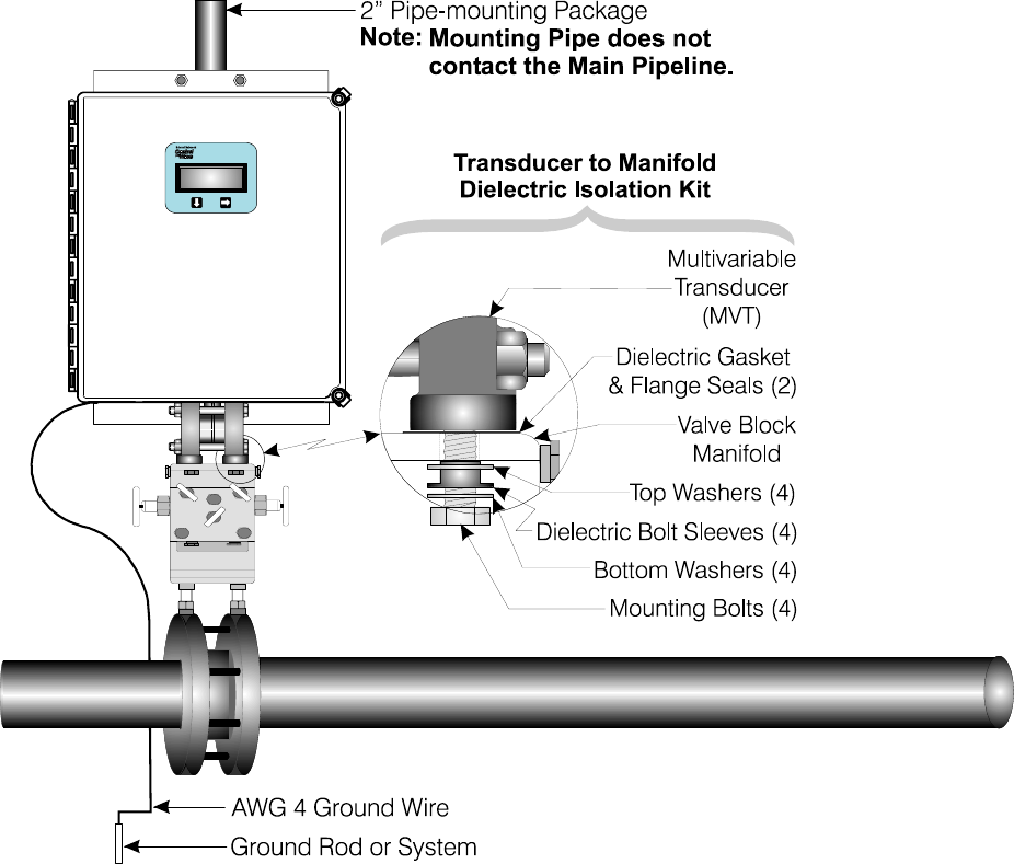
Section 3 - Grounding & Isolation Page 3-9 S1400CW
• all conductive tubing that runs between the pipeline and mounting valve manifold
and/or the units multivariable pressure transducer
• all conductive connections or tubing runs between the ControlWave EFM/GFC and
turbine meter, pulse transducer, or any input other device that is mounted on the
pipeline
• any Temperature Transducer, Pressure Transmitter, etc. and their mount/interface to
the pipeline
Figure 3-9 - ControlWave EFM (Installation is similar to EFM/GFC/XFC)
Direct Mount Installation (with Cathodic Protection)
The ground conductor connects between the ControlWave EFM/GFC/XFC’s Ground Lug
and a known good earth ground. Connect the cases of Temperature Transducers, Pressure
Transmitters, etc., to the known good earth ground. If the mounting 2-inch pipe is in
continuity with the pipeline it will have to be electrically isolated from the ControlWave
EFM/GFC/XFC. Use a strong heat-shrink material such as RAYCHEM WCSM 68/22 EU
3140. This black tubing will easily slip over the 2-inch pipe and then after uniform heating
(e.g., with a rose-bud torch) it electrically insulates and increases the strength of the pipe
stand.
Click here to return to Table of Contents

S1400CW Page 3-10 Section 3 - Grounding & Isolation
See BBI Specification Summary F1670SS-0a for information on PGI Direct Mount Systems
and Manifolds.
Figure 3-10 – ControlWave EFM (Installation is similar to GFC/XFC)
Remote Installation (with Cathodic Protection)
Click here to return to Table of Contents

Section 4 - Lightning & Surge Page 4-1 S1400CW
Section 4 - Lightning Arresters & Surge Protectors
4.1 STROKES & STRIKES
Lightning takes the form of a pulse that typically has a 2 µS rise and a 10 µS to 40 µS decay
to a 50% level. The IEEE standard is an 8 µS by 20 µS waveform. The peak current will
average 18 KA for the first impulse and about half of that for the second and third
impulses. Three strokes (impulses) is the average per lightning strike. The number of
visible flashes that may be seen is not necessarily the number of electrical strokes.
A lightning strike acts like a constant current source. Once ionization occurs, the air
becomes a luminous conductive plasma reaching up to 60,000° F. The resistance of a struck
object is of little consequence except for the power dissipation on the object (I2 x R). Fifty
percent of all lightning strikes will have a first impulse of at least 18 KA, ten percent will
exceed the 60 KA level, and only about one percent will exceed 120 KA.
4.1.1 Chance of Being Struck by Lightning
The map of Figure 4-1 shows the average annual number of thunderstorm days
(Isokeraunic level) for the various regions within the continental U.S.A. This map is not
representative of the severity of the storm or the number of lightning strikes since it does
not take into account more than one lightning strike in a thunderstorm day. The
Isokeraunic or Isoceraunic number provides a meteorological indication of the frequency of
thunderstorm activity; the higher the Isokeraunic number the greater the lightning strike
activity for a given area. These levels vary across the world from a low of 1 to a high of 300.
Within the United States the Isokeraunic level varies from a low of 1 to a high of 100.
Figure 4-1 - Average Thunderstorm Days of the Year (for Continental USA)
Click here to return to Table of Contents

S1400CW Page 4-2 Section 4 - Lightning & Surge
Thunderstorms are cloud formations that produce lightning strikes (or strokes). Across the
United States there is an average of 30 thunderstorm days per year. Any given storm may
produce from one to several strokes. Data on the subject indicates that for an average area
within the United States there can be eight to eleven strokes to each square mile per year.
The risk of stroke activity is increased for various areas such central Florida where up to 38
strokes to each square mile per year are likely to occur.
To determine the probability of a given structure (tower, building, etc.) (within your
location) being struck, perform the following computation:
1. Using the map of Figure 4-1 (or a comparable meteorological map for your local), find
the Isokeraunic level (I) for your area. Then using Chart 1, find “A” for your area.
2. Refer to Figure 4-1 to find the latitude. Then using Chart 2, find “B” for your latitude
(Lat.°).
3. Multiply “A” x “B” to get “C”.
4. To calculate the number of lightning strikes per year that are likely to strike a given
object (tower, mast, etc.), use the equation that follows (where “C” was calculated in
step 3 and “H” is equal to the height of the object.
Strikes Per Year = (“C” x H2) ÷ (.57 x 106 )
Chart 1 Chart 2
I “A” LAT.° “B”
5 8 25 .170
10 26 30 .200
20 85 35 .236
30 169 40 .280
40 275 45 .325
50 402
60 548
70 712 Note for these charts:
80 893 I = Thunderstorm Days Per Year (Isokeraunic Number)
90 1069 A = Stroke activity for associated Isokeraunic Area
100 1306 B = Height/Stroke coefficient for associated latitude
For Example: On Long Island, New York (Isokeraunic number 20), Chart 1 gives “A” to
equal 85. The latitude is approximately 40°. Referring to Chart 2, “B” is found to be equal to
.28. “C” for this example is equal to 23.80. Using the equation for strikes per year, it is
determined that a 100-foot tower has .4 chances per year of being struck by lightning.
Assuming that no other structures are nearby, the tower will more than likely be struck by
lightning at least once in three years.
Note: The Isokeraunic activity numbers connoted as I, “A” and “B” in Charts 1 and 2 above
are provided for the continental United States. Isokeraunic data for various countries
is available from various federal or state Civil Engineering or Meterorelogical
organizations. This information is typically available from manufacturers of lightning
strike protection equipment (such as Lightning Arresters).
Since ControlWave, ControlWave MICRO, ControlWave EFM/GFC/XFC, Control-
WaveLP and ControlWaveEXP units are dc operated systems that are isolated from AC
grids, they are typically immune to lightning strikes to power lines or power equipment
(except for inductive flashover due to close installation proximity). However, once a radio or
Click here to return to Table of Contents
Section 4 - Lightning & Surge Page 4-3 S1400CW
modem has been interfaced to a ControlWave, ControlWave MICRO, ControlWave
EFM/GFC/XFC, ControlWaveLP, or ControlWaveEXP the possibility of damage due to a
lightning strike on power or telephone lines or to a radio antenna or the antenna’s tower
must be considered. It is recommended that the additional lightning protection
considerations listed below be followed for units installed in areas with a high possibility or
history of stroke activity.
Units interfaced to a modem: In series with the phone line (as far away as possible
from the equipment) - for indoor installations the lightning arrester should typically be
located at the point where the line enters the structure.
Units interfaced to a radio: Mount antenna discharge unit (lightning arrester) as
close as possible to where the lead in wire enters the structure. See Antenna Caution
below.
4.1.2 Antenna Caution
Each year hundreds of people are killed, mutilated, or receive severe permanent injuries
when attempting to install or remove an antenna or antenna lead. In many cases, the
victim was aware of the danger of electrocution but failed to take adequate steps to avoid
the hazard. For your safety, and for proper installation maintenance, please read and
follow the safety precautions that follow - they may save your life.
i When installing or servicing an antenna:
DO NOT use a metal ladder. DO NOT step onto or touch an antenna mast while power
is applied to an associated radio unless the radio is a low power (low current) type.
DO NOT work on a wet or windy day, especially during a thunderstorm or when there is
lightning or thunder in your area. Dress properly; shoes with rubber soles and heels,
rubber gloves, long sleeve shirt or jacket.
i The safe distance from power lines should be at least twice the height of the antenna
and mast combination.
i Antenna Grounding per National Electrical Code Instructions:
A. Use AWG 10 or 8 aluminum or AWG 1 copper-clad steel or bronze wire, or larger as
ground wires for both the mast and lead-in. Securely clamp the wire to the bottom of
the mast.
B. Secure lead-in wire from antenna to antenna discharge (lightning arrester) unit and
the mast ground wire to the structure (building, shed, etc.) with stand-off insulators
spaced from 4 feet (1.22 meters) to 6 feet (1.83 meters) apart.
C. Mount antenna discharge unit as close as possible to where the lead-in wire enters
the structure.
D. The hole drilled through the wall for the lead-in wire should be just large enough to
accommodate the cable. Before drilling this hole, make sure there are no wires or
pipes, etc. in the wall.
E. Push the cable through the hole and form a rain drip loop close to where the wire
enters the exterior of the structure.
F. Caulk around the lead-in wire (where it enters the structure) to keep out drafts.
G. Install lightning arresters (antenna discharge units). The grounding conductor
should be run in as straight a line as practicable from the antenna mast and/or the
antenna discharge units to grounding electrode(s).
H. Only connect the antenna cable to the radio after the mast has been properly
grounded and the lead-in cable has been properly connected to lightning arresters
which in turn have each been properly connected to a known good earth ground.
Click here to return to Table of Contents
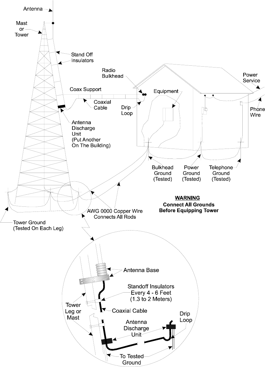
S1400CW Page 4-4 Section 4 - Lightning & Surge
Figure 4-2 - Radio Antenna Field Installation Site Grounding Diagram
For all systems it is best to have all communication equipment input/output grounds tied
together. In the case of ControlWave units, this is accomplished via the unit’s Chassis
Ground (Typically at a ground lug, ground bus or ground plate). However additional
Click here to return to Table of Contents
Section 4 - Lightning & Surge Page 4-5 S1400CW
communication equipment lightning arresters and surge suppressors should be tied to the
same system ground. System ground consists of the tower leg grounds utility ground and
bulkhead-equipment ground-stakes that are tied together via bare copper wire.
4.1.3 Ground Propagation
As in any medium, a dynamic pulse, like R.F., will take time to propagate. This propagation
time will cause a differential step voltage to exist in time between any two ground rods that
are of different radial distances from the strike. With a ground rod tied to a struck tower,
the impulse will propagate its step voltage outwardly from this rod in ever-expanding
circles, like a pebble thrown into a pond. If the equipment house has a separate ground rod
and the power company and/or telephone company grounds are also separate, the dynamic
step voltage will cause currents to flow to equalize these separate ground voltages. Then if
the coax cable (associated with a radio) is the only path linking the equipment chassis with
the tower ground, the surge can destroy circuitry.
4.1.4 Tying it all Together
To prevent this disaster from occurring, a grounding system must be formed which
interconnects all grounds together. This will equalize and distribute the surge charge to all
grounds, and at the same time, it will make for a lower surge impedance ground system.
This interconnection can be done as a grid, where each ground has a separate line to each
other ground, or by using a “rat Race” ring which forms a closed loop (not necessarily a
perfect circle) which surrounds the equipment house completely.
By making this interconnection, it will be necessary to use proper I/O protectors for the
equipment. Of course, these should be a requirement regardless of whether this grounding
technique is used. I/O protectors are used for power lines (even those these don’t feed into a
ControlWave unit), telephone lines, and also to minimize EMI pick-up from a strike.
Ideally it is best to place all I/O protectors on a common panel that has a low inductance
path to the ground system. The ControlWave units would then have a single ground point
from its Chassis Ground Terminal/Ground Lug to this panel. In lieu of this, the
ControlWave unit in question should be tied to a ground rod that in turn is connected to
the Earth/System Ground created for the site.
Your protected equipment connected to a common single ground system, will now be just
like a bird sitting on a high tension wire. When lightning strikes, even with a 50 ohm surge
impedance ground system, the entire system consisting of equipment, ground system,
building, etc., will all rise together to the one million volt peak level (for example) and will
all decay back down together. So long as there is no voltage differential (taken care of by
protectors and ground interconnections, there will be no current flow through the
equipment and therefore no resulting equipment damage.
4.1.5 Impulse Protection Summary
i Use more than one ground rod.
i Place multi-ground stakes more than their length apart.
i Tie Power, Telco, Tower, Bulkhead and equipment ground together.
i Make all ground interconnect runs that are above ground with minimum radius
bends of eight inches and run them away from other conductors and use large solid
wire or a solid strap.
Click here to return to Table of Contents

S1400CW Page 4-6 Section 4 - Lightning & Surge
i Watch out for dissimilar metals connections and coat accordingly.
i Use bare wire radials together where possible with ground stakes to reduce ground
system impedance.
i Use I/O protectors (Phone line, Radio) with a low inductance path to the ground
system.
i Ground the Coaxial Cable Shield (or use an impulse suppressor) at the bottom of the
tower just above the tower leg ground connection.
4.2 USE OF LIGHTNING ARRESTERS & SURGE PROTECTORS
Units equipped with radios or modems use lightning arresters and surge protectors to
protect equipment from lightning strikes, power surges and from damaging currents that
have been induced onto communication lines.
The first line of defense is the Lightning Arrester. These devices typically use gas discharge
bulbs that can shunt high currents and voltages to earth ground when they fire. The high
current, high voltage gas discharge bulb has a relatively slow response time and only fire
when their gas has been ionized by high voltage.
The second line of defense is the Surge Protector, which is made of solid state devices, fires
very quickly and conducts low voltages and currents to ground. Surge protectors are built
into BBI 9600 bps modems.
Lightning Arresters are applied to circuits as follows:
i Equipment or circuits that can be exposed to lightning strikes, falling power lines,
high ground currents caused by power system faults, by operational problems on
electric railways, etc.
i Equipment installed in dry, windy areas, such as the Great Plains and the
Southwest Desert in the United States. Wind and wind blown dust can cause high
voltages (static) to appear on overhead wires, fences, and metal buildings.
Note: Lightning Arresters may explode if lightning strike is very close. Mount
lightning arresters where flying parts won't cause injury to equipment or
personnel.
Click here to return to Table of Contents

Section 5 - Wiring Techniques Page 5-1 S1400CW
Section 5 - Wiring Techniques
5.1 OVERVIEW
This section provides information pertaining to good wiring practices. Installation of Power
and “Measurement & Control” wiring is discussed. Information on obscure problems,
circulating ground and power loops, bad relays, etc. is presented. Good wire preparation
and connection techniques along with problems to avoid are discussed.
5.2 INSTRUMENT WIRING
Each of the rules listed below is briefly discussed; the emphasis herein is placed on the
avoidance of problems as well as equipment safety.
Rule 1 - Never utilize common returns.
Rule 2 - Use twisted shielded pairs (with overall insulation) on all Signal/Control circuits.
Rule 3 - Ground cable shields at one end only.
Rule 4 - Use known good earth grounds (Rod, Bed, System) and test them periodically,
Rule 5 - Earth connections must utilize smoothly dressed large wire.
Rule 6 - Perform all work neatly and professionally.
Rule 7 - Route high power conductors away from signal wiring according to NEC Rules.
Rule 8 - Use appropriately sized wires as required by the load.
Rule 9 - Use lightning arresters and surge protectors.
Rule 10 - Make sure all wiring connections are secure.
5.2.1 Common Returns
Use of common returns on I/O wiring is one of the most common causes of obscure and
difficult to troubleshoot control signal problems. Since all wires and connections have
distributed resistance, inductance and capacitance, the chances of a achieving a balanced
system when common returns are present is very remote. Balanced systems (or circuits) are
only achieved when all currents and voltages developed in association with each of the
common returns are equal. In a balanced system (or circuit) there are no noise or
measurment errors introduced due to by “sneak circuits.”
The illustration of Figure 5-1 shows the difference between testing an I/O circuit that is
discrete and has no sneak circuits and one that utilizes common returns. Common sense
tells us that it is tough to mix up connections to a twisted shielded pair (with overall vinyl
covering) to every end device. Do yourself a favor; to make start up easier, DON’T USE
COMMON RETURNS!
Click here to return to Table of Contents
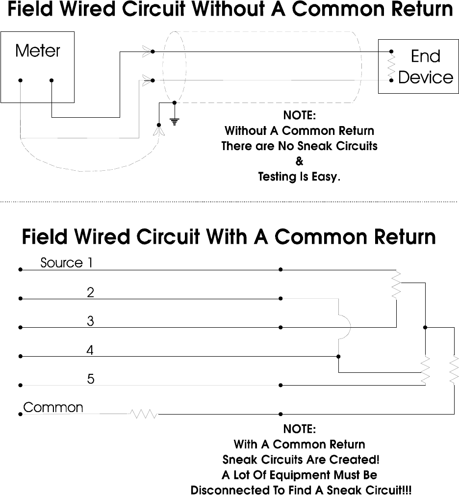
S1400CW Page 5-2 Section 5 - Wiring Techniques
Figure 5-1 - Field Wired Circuits With & Without A Common Return
5.2.2 Use of Twisted Shielded Pair Wiring (with Overall Insulation)
For all field I/O wiring the use of twisted shielded pairs with overall insulation is highly
recommended. This type of cable provides discrete insulation for each of the wires and an
additional overall insulated covering that provides greater E.M.I. immunity and protection
to the shield as well.
Click here to return to Table of Contents
Section 5 - Wiring Techniques Page 5-3 S1400CW
5.2.3 Grounding of Cable Shields
DO NOT connect the cable shield to more than one ground point; it should only be grounded
at one end. Cable shields that are grounded at more than one point or at both ends may
have a tendency to induce circulating currents or sneak circuits that raise havoc with I/O
signals. This will occur when the ground systems associated with multipoint connections to
a cable shield have a high resistance or impedance between them and a ground induced
voltage is developed (for what ever reason, i.e., man made error or nature produced
phenomena).
5.2.4 Use of Known Good Earth Grounds
ControlWave units should only have one connection to earth ground. For ControlWave
and ControlWave MICRO Process Automation Controllers, ControlWave MICRO,
ControlWave EFM Electronic Flow Meters, ControlWave GFC/XFC Gas Flow Computers
and ControlWave I/O Expansion Racks, this connection is provided via the Ground Lug
that is situated on the bottom of the unit. ControlWaveLPs require the installation of a
ground lug, ground bus or ground plate/panel. Since ControlWave units are DC-based
systems, grounding does not take into account AC power grounding considerations. Earth
grounding the unit is absolutely necessary when the unit is equipped with a radio or
modem. Additionally these units should be connected to earth ground when they are
installed in areas that have frequent lightning strikes or are located near or used in
conjunction with equipment that is likely to be struck by lightning or if struck by lightning
may cause equipment or associated system failure. Earth Grounds must be tested and must
be known to be good before connecting the ControlWave. Earth grounds must be
periodically tested and maintained (see Section 4).
5.2.5 Earth Ground Wires
Earth connections must utilize smoothly dressed large wire. Use AWG 3 or 4 stranded
copper wire with as short a length as possible. Exercise care when trimming the insulation
from the wire ends. Twists the strands tightly, trim off any frizzes and tin the ends with
solder. The earth ground wire should be clamped or brazed to the Ground Bed Conductor
(that is typically a standard AWG 0000 copper cable. The earth ground wire should be run
such that any routing bend in the cable is a minimum 8-inch radius above ground or a
minimum 12-inch radius below ground.
5.2.6 Working Neatly & Professionally
Take pride in your work and observe all site and maintenance safety precautions. After
properly trimming the stranded pair wire ends, twist them in the same direction as their
manufacturer did and then tin them with solder. Install the tinned wire end into it’s
connector and then secure the associated connector’s clamping screw. Remember to check
these connections for tightness from time to time. If solid copper wire is used (in
conjunction with the DC Power System or for Earth Ground) make sure that the conductor
is not nicked when trimming off the insulation. Nicked conductors are potential disasters
waiting to happen. Neatly trim shields and whenever possible, coat them to protect them
and prevent shorts and water entry.
Click here to return to Table of Contents
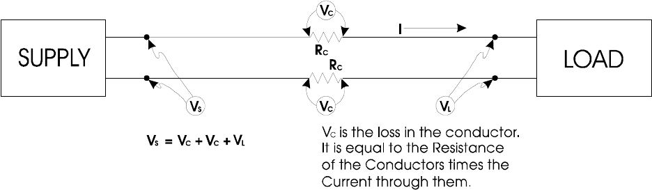
S1400CW Page 5-4 Section 5 - Wiring Techniques
Remember loose connections, bad connections, intermittent connections, corroded connec-
tions, etc., are hard to find, waste time, create system problems and confusion in addition to
being costly.
5.2.7 High Power Conductors and Signal Wiring
When routing wires, keep high power conductors away from signal conductors. Space wires
appropriately to vent high voltage inductance. Refer to the National Electrical Code
Handbook for regulatory and technical requirements.
5.2.8 Use of Proper Wire Size
ControlWaves utilize compression-type terminals that accommodate up to #14 AWG gauge
wire. A connection is made by inserting the bared end (1/4 inch max.) into the clamp
beneath the screw and securing the screw.
Allow some slack in the wires when making terminal connections. Slack makes the
connections more manageable and minimizes mechanical strain on the PCB connectors.
Provide external strain relief (utilizing Tie Wrap, etc.) to prevent the loose of slack at the
ControlWave.
Be careful to use wire that is appropriately sized for the load. Refer to equipment
manufacturer’s Specs. and the National Electrical Code Handbook for information on wire
size and wire resistance. After installing the field wiring, test each load to determine if the
correct voltage or current is present at the load. If you know the resistance of the field wires
(Circular Mills x Length) you should be able to calculate the load voltage. Conversely, if you
know the minimum load voltage and current, you should be able to derive the maximum
voltage loss that is allowable due to line resistance and then the correct wire size.
Referring to Figure 5-2, a relay that is picked by 100 mA, with a loop supply voltage of 24V
and a total line resistance of 20 ohms, the load voltage (voltage across the relay) should be:
VL = VS - (VC + VC) where VC + VC = (RC + RC) I
22 = 24 - 2 where 2V = (20 Ω) x 0.1 A
Figure 5-2 - Calculating Load Voltage due to Line Resistance
5.2.9 Lightning Arresters & Surge Protectors
Use lightning arresters in association with any radio or modem equipped unit. BBI 9600
bps modems are equipped with surge protection circuitry. Lightning arresters or Antenna
Click here to return to Table of Contents
Section 5 - Wiring Techniques Page 5-5 S1400CW
Discharge Units should be placed on the base of the antenna and at the point where the
antenna lead (typically coax) enters the site equipment building. When a modem is used, a
lightning arrester should be placed at the point where the phone line enters the site
equipment building. If you use a modem (manufactured by other than BBI) it is
recommended that you also install a surge suppressors or lightning arrester on the phone
line as close to the modem as possible. Any unit interfaced to a radio or modem must be
connected to a known good earth ground.
5.2.10 Secure Wiring Connections
Make sure that all wiring connections are secure. In time wires that were once round will
become flattened due to the pressure applied by screw compression type terminals and site
vibrations. After a while these compression screws have a tendency to become loose. Part of
a good maintenance routine should be to check and tighten all screws associated with
wiring terminal connections. Avoid nicking the wire(s) when stripping insulation.
Remember, nicked conductors will lead to future problems. Also remember to provide some
cabling slack and strain relief.
If installing stranded or braided wiring that has not been tinned, be sure to tightly twist
the end (in the same direction as manufactured) and then trim off any frizzed wires.
Click here to return to Table of Contents
BLANK PAGE
Click here to return to Table of Contents

READER RESPONSE FORM
Please help us make our documentation more useful to you! If you have a complaint, a sug-
gestion, or a correction regarding this manual, please tell us by mailing this page with your
comments. It's the only way we know we're doing our job by giving you correct, complete, and
useful documentation.
DOCUMENT NUMBER: S1400CW
TITLE: ControlWaveTM SITE CONSIDERATIONS For EQUIPMENT INSTALLATION,
GROUNDING & WIRING
ISSUE DATE: APR., 2005
COMMENT/COMPLAINT:
______________________________________________________________________________
______________________________________________________________________________
______________________________________________________________________________
______________________________________________________________________________
______________________________________________________________________________
______________________________________________________________________________
______________________________________________________________________________
______________________________________________________________________________
______________________________________________________________________________
______________________________________________________________________________
______________________________________________________________________________
______________________________________________________________________________
______________________________________________________________________________
Mail this page to:
Bristol Babcock Inc.
1100 Buckingham Street
Watertown, CT 06795
Attn: Technical Publications Group, Dept. 315
Click here to return to Table of Contents

U.S.A. Locations:
Northern Region
Bristol Babcock Inc.
1100 Buckingham Street
Watertown, CT 06795
Phone: +1 (860) 945-2381
Fax: +1 (860) 945-2525
NorthernUS@bristolbabcock.com
Gulf Coast Region
Bristol Babcock Inc.
2000 Governor's Circle
Suite F
Houston, TX 77092-8731
Phone: +1 (713) 685-6200
Fax: +1 (713) 681-7331
SouthwestUS@bristolbabcock.com
Western Region
Bristol Babcock Inc.
1609 South Grove Avenue
Suites 106 & 107
Ontario, CA 91761
Phone: +1 (909) 923-8488
Fax: +1 (909) 923-8988
WesternUS@bristolbabcock.com
Southeast Region
Bristol Babcock Inc.
317 S. North Lake Blvd.
Suite 1016
Altamonte Springs, FL 32701
Phone: +1 (407) 740-7084
Fax: +1 (407) 629-2106
SoutheastUS@bristolbabcock.com
Helicoid Instruments
1100 Buckingham Street
Watertown, CT 06795
Phone: +1 (860) 945-2218
Fax: +1 (860) 945-2213
jmcgrail@bristolbabcock.com
Central Region
Bristol Babcock Inc.
300 North Coit Road
Suite 1300
Richardson, TX 75080
Phone: +1 (972) 238-8935
Fax: +1 (972) 238-8198
dallas@bristolbabcock.com
Rocky Mountain Region
Bristol Babcock Inc.
906 San Juan Blvd., Suite A
Farmington, NM 87401
Phone: +1 (505) 320-5046
Fax: +1 (505) 327-3273
NewMexUS@bristolbabcock.com
Communications
Technology Group
Bristol Babcock Inc.
317 S. North Lake Blvd.
Suite 1016
Altamonte Springs, FL 32701
Phone: +1 (407) 629-9464
Fax: +1 (407) 629-2106
orlandoRFgroup@bristolbabcock.com
International Affiliates:
Canada
Bristol Babcock, Canada
234 Attwell Drive
Toronto, Ont. M9W 5B3
Canada
PH: 416-675-3820
FAX: 416-674-5129
info@bristolbabcock.ca
Calgary Office
Bristol Babcock, Canada
3812 Edmonton Trail N.E.
Calgary, Alberta T2E 5T6
Canada
PH: 403-265-4808
FAX: 403-233-2914
janetl@bristolbabcock.ca
Mexico
BBI, S.A. de C.V.
Homero No. 1343, 3er Piso
Col. Morales Polanco
11540 Mexico, D.F.
Mexico
PH: (52-55)-52-81-81-12
FAX: (52-55)-52-81-81-09
Mexico@bristolbabcock.com
Villahermosa Office
BBI, S.A. de C.V.
Av. Plomo No.2
Bodega No. 1 - Ciudad
Industrial
Villahermosa, Tabasco 86010
Mexico
PH: 52-993-353-3142
FAX: 52-993-353-3145
bbivsa@prodigy.net.mx
United Kingdom
Bristol Babcock Ltd.
Blackpole Road
Worcester, WR3 8YB
United Kingdom
PH: +44 (0) 1905 856950
FAX: +44 (0) 1905 856969
enquiries@bristol-babcock.com
Middle East
Bristol Babcock Ltd.
Blackpole Road
Worcester, WR3 8YB
United Kingdom
PH: +44 (0) 1905 856950
FAX: +44 (0) 1905 856969
enquiries@bristol-babcock.com
Asia Pacific
Bristol Babcock, Inc.
PO Box 1987
Bunbury, Western Australia
6231
PH: +61 (0) 8 9791 3654
FAX: +61 (0) 8 9791 3173
dtrench@bdsa.com.au
Victoria, Australia
PH: +61 (0) 3 9384 2171
FAX: +61 (0) 3 8660 2501
RC Rev: 05-Feb-04
Br
i
stol Babcoc
k
1100 Buckingham Street
Watertown, CT 06795
Phone: +1 (860) 945-2200
Fax: +1 (860) 945-2213
Website: www.bristolbabcock.com
Click here to return to Table of Contents
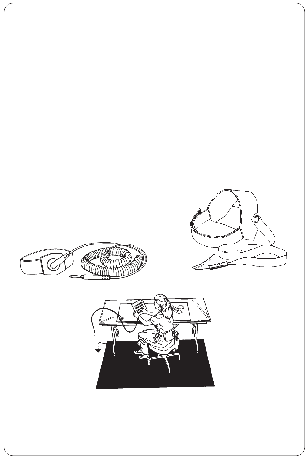
BLANK PAGE
Click here to return to Table of Contents
1
ESDS Manual
S14006
4/15/92
TABLE OF CONTENTS
PAGE
TOOLS AND MATERIALS REQUIRED 1
ESD-SENSITIVE COMPONENT HANDLING PROCEDURE 2
1. Introduction 2
2. General Rules 3
3. Protecting ESD-Sensitive Components 5
4. Static-Safe Field Procedure 6
5. Cleaning and Lubricating 8
6. Completion 10
TOOLS AND MATERIALS REQUIRED
1. Tools
Anti-Static Field kit. It is recommended that an anti-static field kit be kept on any
site where solid-state printed circuit boards and other ESD-sensitive compo-
nents are handled. These kits are designed to remove any existing static charge
and to prevent the build-up of a static charge that could damage a PC board or
ESD-sensitive components. The typical anti-static field kit consists of the
following components:
1. A work surface (10mm conductive plastic sheet with a female snap
fastener in one corner for ground cord attachment).
2. A 15-foot long ground cord for grounding the work surface.
3. Wrist strap (available in two sizes, large and small, for proper fit and
comfort) with a female snap fastener for ground cord attachment.
4. A coiled ground cord with a practical extension length of 10 feet for
attachment to the wrist strap.
Toothbrush (any standard one will do)
Click here to return to Table of Contents
2
ESDS Manual
#S14006
4/15/92
2. Materials
●●
●●
●Inhibitor
(Texwipe Gold Mist ; Chemtronics Gold Guard, or equivalent)
●●
●●
●Cleaner
(Chemtronics Electro-Wash; Freon TF, or equivalent)
●●
●●
●Wiping cloth (Kimberly-Clark Kim Wipes, or equivalent)
ESD-SENSITIVE COMPONENT HANDLING PROCEDURE
1. Introduction
Microelectronic devices such as PC boards, chips and other components are electro-
static-sensitive. Electrostatic discharge (ESD) of as few as 110 volts can damage or
disrupt the functioning of such devices. Imagine the damage possible from the 35,000
volts (or more) that you can generate on a dry winter day by simply walking across a
carpet. In fact, you can generate as much as 6,000 volts just working at a bench.
There are two kinds of damage that can be caused by the static charge. The more
severe kind results in complete failure of the PC board or component. This kind of
damage is relatively simple, although often expensive, to remedy by replacing the
affected item(s). The second kind of damage results in a degradation or weakening
which does not result in an outright failure of the component. This kind of damage is
difficult to detect and often results in faulty performance, intermittent failures, and
service calls.
Minimize the risk of ESD-sensitive component damage by preventing static build-up and
by promptly removing any existing charge. Grounding is effective, if the carrier of the
static charge is conductive such as a human body. To protect components from
nonconductive carriers of static charges such as plastic boxes, place the component
in static-shielding bags.
This manual contains general rules to be followed while handling ESD-sensitive
components. Use of the anti-static field kit to properly ground the human body as well
as the work surface is also discussed.
Click here to return to Table of Contents

3
ESDS Manual
S14006
4/15/92
Table 1
Typical Electrostatic Voltages
Electrostatic Voltages
Means of Static 10-20 Percent 65-90 Percent
Generation Relative Humidity Relative Humidity
Walking across carpet 35,000 1,500
Walking over vinyl floor 12,000 250
Worker at bench 6,000 100
Vinyl envelopes for work instructions 7,000 600
Poly bag picked up from bench 20,000 1,200
Work chair padded with poly foam 18,000 1,500
2. General Rules
(1) ESD-sensitive components shall only be removed from their static-shielding
bags by a person who is properly grounded.
(2) When taken out of their static-shielding bags, ESD-sensitive components shall
never be placed over, or on, a surface which has not been properly grounded.
(3) ESD-sensitive components shall be handled in such a way that the body does
not come in contact with the conductor paths and board components. Handle
ESD-sensitive components in such a way that they will not suffer damage from
physical abuse or from electric shock.
(4) EPROMS/PROMS shall be kept in anti-static tubes until they are ready to use
and shall be removed only by a person who is properly grounded.
(5) When inserting and removing EPROMS/PROMS from PC boards, use a chip
removal tool similar to the one shown in the figure following. Remember, all work
should be performed on a properly grounded surface by a properly-grounded
person.
Click here to return to Table of Contents

4
ESDS Manual
#S14006
4/15/92
(6) It is important to note when inserting EPROMS/PROMS, that the index notch on
the PROM must be matched with the index notch on the socket. Before pushing
the chip into the socket, make sure all the pins are aligned with the respective
socket-holes. Take special care not to crush any of the pins as this could destroy
the chip.
(7) Power the system down before removing or inserting comb connectors/plugs or
removing and reinstalling PC boards or ESD-sensitive components from card
files or mounting hardware. Follow the power-down procedure applicable to the
system being serviced.
(8) Handle all defective boards or components with the same care as new compo-
nents. This helps eliminate damage caused by mishandling. Do not strip used PC
boards for parts. Ship defective boards promptly to Bristol Babcock in a static-
shielding bag placed
inside
static-shielding foam and a box to avoid damage
during shipment.
Typical Chip Removal Tool
Click here to return to Table of Contents
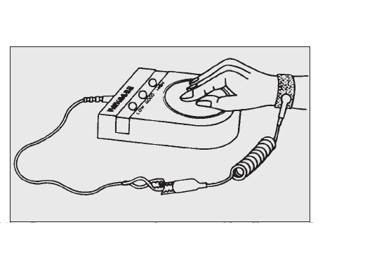
5
ESDS Manual
S14006
4/15/92
CAUTION
Don't place ESD-sensitive components and paperwork in the same bag.
The static caused by sliding the paper into the bag could develop a charge and
damage the component(s).
(9) Include a note, which describes the malfunction, in a
separate
bag along with each
component being shipped. The repair facility will service the component and
promptly return it to the field.
3. Protecting ESD-Sensitive Components
(1) As stated previously, it is recommended that an electrically-conductive anti-static
field kit be kept on any site where ESD-sensitive components are handled. A
recommended ESD-protective workplace arrangement is shown on page 7. The
anti-static safety kit serves to protect the equipment as well as the worker. As a safety
feature, a resistor (usually of the one-megohm, 1/2-watt, current-limiting type) has
been installed in the molded caps of the wrist strap cord and the ground cord. This
resistor limits current should a worker accidently come in contact with a power
source. Do not remove the molded caps from grounded cords. If a cord is damaged,
replace it immediately.
(2) Be sure to position the work surface so that it does not touch grounded conductive
objects. The protective resistor is there to limit the current which can flow through
the strap. When the work surface touches a grounded conductive object, a short is
created which draws the current flow and defeats the purpose of the current-limiting
resistor.
(3) Check resistivity of wrist strap periodically using a commercially-available system
tester similar to the one shown in the figure below:
Click here to return to Table of Contents

6
ESDS Manual
#S14006
4/15/92
Note: If a system checker is not available, use an ohmmeter connected to the cable
ends to measure its resistance. The ohmmeter reading should be 1 megohm +/-
15%. Be sure that the calibration date of the ohmmeter has not expired. If the
ohmmeter reading exceeds 1 megohm by +/- 15%, replace the ground cord with a
new one.
4. Static-safe Field Procedure
(1) On reaching the work location, unfold and lay out the work surface on a convenient
surface (table or floor). Omit this step if the table or floor has a built-in ESD-safe work
surface.
(2) Attach the ground cord to the work surface via the snap fasteners and attach the
other end of the ground cord to a reliable ground using an alligator clip.
(3) Note which boards or components are to be inserted or replaced.
(4) Power-down the system following the recommended power-down procedure.
(5) Slip on a known-good wristband, which should fit snugly; an extremely loose fit is not
desirable.
(6) Snap the ground cord to the wristband. Attach the other end of the ground cord to
a reliable ground using the alligator clip.
Click here to return to Table of Contents
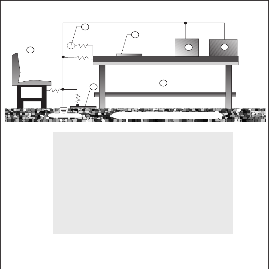
7
ESDS Manual
S14006
4/15/92
(7) The components can now be handled following the general rules as described
in the instruction manual for the component.
(8) Place the component in a static-shielding bag before the ground cord is
disconnected. This assures protection from electrostatic charge in case the work
surface is located beyond the reach of the extended ground cord.
NOTE: ALL RESISTORS 1M +/-10% 1/2W
Ω
✰
FLOOR OF BUILDING
EARTH GROUND
A
B
C
D
EF
G
✰
RR
R
R
A - Chair with ground (optional)
B - ESD protective floor mat (optional)
C - Wrist strap
D - ESD protective trays, etc.
E - Ionizer
F - Other electrical equipment
G - Workbench with ESD protective table top
LEGEND
Click here to return to Table of Contents
8
ESDS Manual
#S14006
4/15/92
(9) If a component is to undergo on-site testing, it may be safely placed on the
grounded work surface for that purpose.
(10) After all component work is accomplished, remove the wrist straps and ground
wire and place in the pouch of the work surface for future use.
5. Cleaning And Lubricating
The following procedure should be performed periodically for all PC boards and
when a PC board is being replaced.
CAUTION
Many PC board connectors are covered with a very fine gold-plate.
Do not use any abrasive cleaning substance or object such as a pencil eraser to
clean connectors.
Use only the approved cleaner/lubricants specified in the procedure following.
WARNING
Aerosol cans and products are extremely combustible.
Contact with a live circuit, or extreme heat can cause an
explosion.
Turn OFF all power and find an isolated, and ventilated
area to use any aerosol products specified in this proce-
dure.
(1) Turn the main line power OFF. Blow or vacuum out the component. This should
remove potential sources of dust or dirt contamination during the remainder of
this procedure.
Click here to return to Table of Contents
9
ESDS Manual
S14006
4/15/92
(2) Clean PC board connectors as follows:
a. Review the static-safe field procedure detailed earlier.
b. Following the ESD-sensitive component handling procedures, remove
the connectors from the boards and remove the PC boards from their
holders.
c. Use cleaner to remove excessive dust build-up from comb connectors
and other connectors. This cleaner is especially useful for removing dust.
d. Liberally spray all PC board contacts with Inhibitor. The inhibitor:
●●
●●
●Provides a long lasting lubricant and leaves a protective film to
guard against corrosion
●●
●●
●Improves performance and reliability
●●
●●
●Extends the life of the contacts
●●
●●
●Is nonconductive, and is safe for use on most plastics
e. Clean the comb contacts using a lint-free wiping cloth.
f. Lightly mist all comb contacts again with Inhibitor.
NOTE: Do not use so much Inhibitor that it drips.
g. Repeat the above procedure for the other PC boards from the device.
(3) Cleaning PC edge connectors
a. Use cleaner to remove excessive dust build-up from connectors. This
cleaner is especially useful for removing dust.
b. Liberally spray the outboard connector with Inhibitor.
c. Lightly brush the outboard connector with a soft, non-metallic, bristle
brush such as a toothbrush.
Click here to return to Table of Contents
10
ESDS Manual
#S14006
4/15/92
d. Spray the connector liberally to flush out any contaminants.
e. Remove any excess spray by shaking the connector or wiping with either
a toothbrush, or a lint-free wiping cloth.
6. Completion
(1) Replace any parts that were removed.
(2) Make sure that the component cover is secure.
(3) Return the system to normal operation.
(4) Check that the component operates normally.
Click here to return to Table of Contents
BLANK PAGE
Click here to return to Table of Contents

Customer Instruction Manual
CI-ControlWave Express
February, 2009
Bristol ControlWave Express (Remote Terminal Unit)
NOTICE
“Remote Automation Solutions (“RAS”), division of Emerson Process
Management shall not be liable for technical or editorial errors in this manual
or omissions from this manual. RAS MAKES NO WARRANTIES,
EXPRESSED OR IMPLIED, INCLUDING THE IMPLIED WARRANTIES OF
MERCHANTABILITY AND FITNESS FOR A PARTICULAR PURPOSE WITH
RESPECT TO THIS MANUAL AND, IN NO EVENT SHALL RAS BE LIABLE
FOR ANY INCIDENTAL, PUNITIVE, SPECIAL OR CONSEQUENTIAL
DAMAGES INCLUDING, BUT NOT LIMITED TO, LOSS OF PRODUCTION,
LOSS OF PROFITS, LOSS OF REVENUE OR USE AND COSTS
INCURRED INCLUDING WITHOUT LIMITATION FOR CAPITAL, FUEL AND
POWER, AND CLAIMS OF THIRD PARTIES.
Bristol, Inc., Bristol Babcock Ltd, Bristol Canada, BBI SA de CV and the Flow
Computer Division are wholly owned subsidiaries of Emerson Electric Co.
doing business as Remote Automation Solutions (“RAS”), a division of
Emerson Process Management. FloBoss, ROCLINK, Bristol, Bristol
Babcock, ControlWave, TeleFlow and Helicoid are trademarks of RAS. AMS,
PlantWeb and the PlantWeb logo are marks of Emerson Electric Co. The
Emerson logo is a trademark and service mark of the Emerson Electric Co.
All other trademarks are property of their respective owners.
The contents of this publication are presented for informational purposes
only. While every effort has been made to ensure informational accuracy,
they are not to be construed as warranties or guarantees, express or implied,
regarding the products or services described herein or their use or
applicability. RAS reserves the right to modify or improve the designs or
specifications of such products at any time without notice. All sales are
governed by RAS’ terms and conditions which are available upon request.
© 2009 Remote Automation Solutions, division of Emerson Process
Management. All rights reserved.
Emerson Process Management
Remote Automation Solutions
1100 Buckingham Street
Watertown, CT 06795
Phone: +1 (860) 945-2262
Fax: +1 (860) 945-2525
www.EmersonProcess.com/Remote
Emerson Process Management
Remote Automation Solutions
6338 Viscount Rd.
Mississauga, Ont. L4V 1H3
Canada
Phone: 905-362-0880
Fax: 905-362-0882
www.EmersonProcess.com/Remote
Emerson Process Management Mexico
Viveros de la Colina No 238
Col. Viveros de la Loma
Tlalnepantla, Mexico 54080
T +52 (55) 57.28.08.00
F +52 (55) 53.66.26.18
www.EmersonProcess.com/Remote
Emerson Process Management, Ltd.
Remote Automation Solutions
Blackpole Road
Worcester, WR3 8YB
United Kingdom
Phone: +44 1905 856950
Fax: +44 1905 856969
www.EmersonProcess.com/Remote
Emerson Process Management AP Pte Ltd.
Remote Automation Solutions Division
1 Pandan Crescent
Singapore 128461
Phone: +65-6770-8584
Fax: +65-6891-7841
www.EmersonProcess.com/Remote
Click here to return to Table of Contents
