Emerson Process Management Electric Co Automobile Accessories 3095Fc Users Manual
3095FC to the manual fbcc7153-3d91-47e3-9eca-6e7da17dd97e
2015-02-06
: Emerson-Process-Management Emerson-Process-Management-Emerson-Process-Management-Emerson-Electric-Co-Automobile-Accessories-3095Fc-Users-Manual-540069 emerson-process-management-emerson-process-management-emerson-electric-co-automobile-accessories-3095fc-users-manual-540069 emerson-process-management pdf
Open the PDF directly: View PDF ![]() .
.
Page Count: 150 [warning: Documents this large are best viewed by clicking the View PDF Link!]
www.rosemount.com
Reference Manual
00809-0100-4832, Rev AA
October 2004
Rosemount 3095FC MultiVariable™
Mass Flow Transmitter

Reference Manual
00809-0100-4832, Rev AA
October 2004 Rosemount 3095FC
www.rosemount.com
Rosemount 3095FC MultiVariable
Mass Flow Transmitter
The products described in this document are NOT designed for nuclear-qualified
applications. Using non-nuclear qualified products in applications that require
nuclear-qualified hardware or products may cause inaccurate readings.
For information on Rosemount nuclear-qualified products, contact an Emerson Process
Management Sales Representative.
This device is intended for use in temperature monitoring applications and should not be
used in control and safety applications.
NOTICE
Read this manual before working with the product. For personal and system safety, and for
optimum product performance, make sure to thoroughly understand the contents before
installing, using, or maintaining this product.
The United States has two toll-free assistance numbers and one International number.
Customer Central
1-800-999-9307 (7:00 a.m. to 7:00 P.M. CST)
International
1-(952) 906-8888
National Response Center
1-800-654-7768 (24 hours a day)
Equipment service needs

Reference Manual
00809-0100-4832, Rev AA
October 2004 Rosemount 3095FC
www.rosemount.com
Table of Contents
SECTION 1
Introduction
3095FC Overview . . . . . . . . . . . . . . . . . . . . . . . . . . . . . . . . . . . . . . . . 1-1
Hardware . . . . . . . . . . . . . . . . . . . . . . . . . . . . . . . . . . . . . . . . . . . . 1-2
Firmware. . . . . . . . . . . . . . . . . . . . . . . . . . . . . . . . . . . . . . . . . . . . . 1-3
Accessories . . . . . . . . . . . . . . . . . . . . . . . . . . . . . . . . . . . . . . . . . . 1-3
Automatic Tests . . . . . . . . . . . . . . . . . . . . . . . . . . . . . . . . . . . . . . . 1-3
Low Power Mode . . . . . . . . . . . . . . . . . . . . . . . . . . . . . . . . . . . . . . 1-4
3095FC Functions . . . . . . . . . . . . . . . . . . . . . . . . . . . . . . . . . . . . . 1-4
Flow Measurement . . . . . . . . . . . . . . . . . . . . . . . . . . . . . . . . . . 1-4
1992 Flow Calculations for Orifice Metering . . . . . . . . . . . . . . . 1-4
Considerations. . . . . . . . . . . . . . . . . . . . . . . . . . . . . . . . . . . . . . . . . . . 1-5
Environmental Requirements . . . . . . . . . . . . . . . . . . . . . . . . . . . . . 1-5
Enclosures . . . . . . . . . . . . . . . . . . . . . . . . . . . . . . . . . . . . . . . . . . . 1-5
Mounting. . . . . . . . . . . . . . . . . . . . . . . . . . . . . . . . . . . . . . . . . . . . . 1-5
Power Installation Requirements . . . . . . . . . . . . . . . . . . . . . . . . . . 1-5
Rosemount User Interface Software PC Requirements . . . . . . . . . 1-6
Site Requirements . . . . . . . . . . . . . . . . . . . . . . . . . . . . . . . . . . . . . 1-6
Wiring Requirements . . . . . . . . . . . . . . . . . . . . . . . . . . . . . . . . . . . 1-6
SECTION 2
Installation
Mounting . . . . . . . . . . . . . . . . . . . . . . . . . . . . . . . . . . . . . . . . . . . . . . . 2-1
Installation . . . . . . . . . . . . . . . . . . . . . . . . . . . . . . . . . . . . . . . . . . . . . . 2-2
Rosemount 3095FC . . . . . . . . . . . . . . . . . . . . . . . . . . . . . . . . . . . . 2-2
Installing the Rosemount 3095FC on a Pipestand . . . . . . . . . . 2-2
Installing the 3095FC on an Orifice Plate (Direct Mount) . . . . . 2-2
Solar Panels . . . . . . . . . . . . . . . . . . . . . . . . . . . . . . . . . . . . . . . . . . 2-3
Solar Panel Sizing . . . . . . . . . . . . . . . . . . . . . . . . . . . . . . . . . . . 2-3
Wiring. . . . . . . . . . . . . . . . . . . . . . . . . . . . . . . . . . . . . . . . . . . . . . . . . . 2-4
Power Supply Wiring . . . . . . . . . . . . . . . . . . . . . . . . . . . . . . . . . . . 2-5
RTD Wiring . . . . . . . . . . . . . . . . . . . . . . . . . . . . . . . . . . . . . . . . . . . 2-5
Communications Wiring . . . . . . . . . . . . . . . . . . . . . . . . . . . . . . . . . 2-6
Local Operator Interface Port (LOI). . . . . . . . . . . . . . . . . . . . . . 2-6
EIA-485 (RS-485) Serial Communications - Comm 1 . . . . . . . . 2-7
EIA-232 (RS-232) Communications - Comm 2 . . . . . . . . . . . . . 2-7
Ground the Transmitter . . . . . . . . . . . . . . . . . . . . . . . . . . . . . . . . . 2-8
Earth Grounds . . . . . . . . . . . . . . . . . . . . . . . . . . . . . . . . . . . . . . 2-8
Pipelines With Cathodic Protection . . . . . . . . . . . . . . . . . . . . . . 2-8
Power Supply. . . . . . . . . . . . . . . . . . . . . . . . . . . . . . . . . . . . . . . . . . . . 2-9
Batteries . . . . . . . . . . . . . . . . . . . . . . . . . . . . . . . . . . . . . . . . . . 2-9
Apply Power. . . . . . . . . . . . . . . . . . . . . . . . . . . . . . . . . . . . . . . . . . . . 2-10
Install the Rosemount User Interface Software . . . . . . . . . . . . . . . . . 2-11
Software Overview . . . . . . . . . . . . . . . . . . . . . . . . . . . . . . . . . 2-11
Install With Autorun . . . . . . . . . . . . . . . . . . . . . . . . . . . . . . . . . . . 2-11
Install Without Autorun . . . . . . . . . . . . . . . . . . . . . . . . . . . . . . . . . 2-12
Uninstalling the Rosemount User Interface Software. . . . . . . . . . 2-12

Reference Manual
00809-0100-4832, Rev AA
October 2004
Rosemount 3095FC
TOC-2
Getting Started with the Software . . . . . . . . . . . . . . . . . . . . . . . . . . . 2-12
Run the Software . . . . . . . . . . . . . . . . . . . . . . . . . . . . . . . . . . . . . 2-12
Log into the Software . . . . . . . . . . . . . . . . . . . . . . . . . . . . . . . . . . 2-12
Establishing Communication . . . . . . . . . . . . . . . . . . . . . . . . . . . . . . . 2-13
Connection Methods. . . . . . . . . . . . . . . . . . . . . . . . . . . . . . . . . . . 2-13
Direct Connect. . . . . . . . . . . . . . . . . . . . . . . . . . . . . . . . . . . . . 2-13
Connect . . . . . . . . . . . . . . . . . . . . . . . . . . . . . . . . . . . . . . . . . . 2-14
Remote Hardware Connection . . . . . . . . . . . . . . . . . . . . . . . . 2-14
Disconnect from the 3095FC. . . . . . . . . . . . . . . . . . . . . . . . . . 2-14
Configuration Tree . . . . . . . . . . . . . . . . . . . . . . . . . . . . . . . . . . . . . . . 2-14
Adding a Group . . . . . . . . . . . . . . . . . . . . . . . . . . . . . . . . . . . . 2-15
Deleting a Group . . . . . . . . . . . . . . . . . . . . . . . . . . . . . . . . . . . 2-15
Adding a 3095FC transmitter . . . . . . . . . . . . . . . . . . . . . . . . . 2-16
Deleting a 3095FC transmitter . . . . . . . . . . . . . . . . . . . . . . . . 2-16
Deleting all 3095FC transmitters . . . . . . . . . . . . . . . . . . . . . . . 2-16
Renaming a Group or 3095FC . . . . . . . . . . . . . . . . . . . . . . . . 2-16
SECTION 3
Configuration
Overview . . . . . . . . . . . . . . . . . . . . . . . . . . . . . . . . . . . . . . . . . . . . . . . 3-1
Basic Functions . . . . . . . . . . . . . . . . . . . . . . . . . . . . . . . . . . . . . . . . . . 3-1
Select TLP Options . . . . . . . . . . . . . . . . . . . . . . . . . . . . . . . . . 3-1
Display TLP Options . . . . . . . . . . . . . . . . . . . . . . . . . . . . . . . . . 3-1
Duplicating a Configuration . . . . . . . . . . . . . . . . . . . . . . . . . . . . 3-2
Using Copy and Paste. . . . . . . . . . . . . . . . . . . . . . . . . . . . . . . . 3-2
New Configuration File . . . . . . . . . . . . . . . . . . . . . . . . . . . . . . . 3-2
Open File. . . . . . . . . . . . . . . . . . . . . . . . . . . . . . . . . . . . . . . . . . 3-2
Save File . . . . . . . . . . . . . . . . . . . . . . . . . . . . . . . . . . . . . . . . . . 3-2
Download File . . . . . . . . . . . . . . . . . . . . . . . . . . . . . . . . . . . . . . 3-3
Print Configuration. . . . . . . . . . . . . . . . . . . . . . . . . . . . . . . . . . . 3-3
Configuration . . . . . . . . . . . . . . . . . . . . . . . . . . . . . . . . . . . . . . . . . . . . 3-4
Setting the Clock . . . . . . . . . . . . . . . . . . . . . . . . . . . . . . . . . . . . . . 3-4
Configuring the System Flags . . . . . . . . . . . . . . . . . . . . . . . . . . . . 3-5
General Tab . . . . . . . . . . . . . . . . . . . . . . . . . . . . . . . . . . . . . . . 3-5
Advanced Tab . . . . . . . . . . . . . . . . . . . . . . . . . . . . . . . . . . . . . . 3-7
3095FC Communications Ports Configuration . . . . . . . . . . . . . . . . 3-8
General Tab . . . . . . . . . . . . . . . . . . . . . . . . . . . . . . . . . . . . . . . 3-8
RBX Tab . . . . . . . . . . . . . . . . . . . . . . . . . . . . . . . . . . . . . . . . . . 3-9
3095FC Device Configuration / Information . . . . . . . . . . . . . . . . . 3-10
General Tab . . . . . . . . . . . . . . . . . . . . . . . . . . . . . . . . . . . . . . 3-10
Points Tab . . . . . . . . . . . . . . . . . . . . . . . . . . . . . . . . . . . . . . . . 3-11
Other Information Tab . . . . . . . . . . . . . . . . . . . . . . . . . . . . . . . 3-12
Revision Info Tab . . . . . . . . . . . . . . . . . . . . . . . . . . . . . . . . . . 3-12
Security Configuration . . . . . . . . . . . . . . . . . . . . . . . . . . . . . . . . . 3-13
Rosemount User Interface Security - Menu and Log On . . . . 3-13
3095FC Security . . . . . . . . . . . . . . . . . . . . . . . . . . . . . . . . . . . 3-14
LCD User List Configuration. . . . . . . . . . . . . . . . . . . . . . . . . . . . . 3-15
I/O Configuration . . . . . . . . . . . . . . . . . . . . . . . . . . . . . . . . . . . . . 3-15
Scanning Disabled versus Scanning Enabled. . . . . . . . . . . . . 3-15
I/O Monitor. . . . . . . . . . . . . . . . . . . . . . . . . . . . . . . . . . . . . . . . 3-15
Analog Input (AI) Configuration . . . . . . . . . . . . . . . . . . . . . . . . . . 3-16
AI General Tab . . . . . . . . . . . . . . . . . . . . . . . . . . . . . . . . . . . . 3-16
AI Advanced Tab. . . . . . . . . . . . . . . . . . . . . . . . . . . . . . . . . . . 3-17
AI Alarms Tab . . . . . . . . . . . . . . . . . . . . . . . . . . . . . . . . . . . . . 3-19

Reference Manual
00809-0100-4832, Rev AA
October 2004
TOC-3
Rosemount 3095FC
Soft Points Configuration . . . . . . . . . . . . . . . . . . . . . . . . . . . . . . . 3-20
Opcode . . . . . . . . . . . . . . . . . . . . . . . . . . . . . . . . . . . . . . . . . . . . . 3-21
Opcode Table Configuration . . . . . . . . . . . . . . . . . . . . . . . . . . 3-22
Radio Power Control Configuration . . . . . . . . . . . . . . . . . . . . . . . 3-23
Meter Run Configuration . . . . . . . . . . . . . . . . . . . . . . . . . . . . . . . 3-25
General Tab . . . . . . . . . . . . . . . . . . . . . . . . . . . . . . . . . . . . . . 3-26
AGA Meter Inputs Tab. . . . . . . . . . . . . . . . . . . . . . . . . . . . . . . 3-27
Gas Quality Tab . . . . . . . . . . . . . . . . . . . . . . . . . . . . . . . . . . . 3-28
Advanced Meter Setup Tab. . . . . . . . . . . . . . . . . . . . . . . . . . . 3-29
Instrument Calibration Tab . . . . . . . . . . . . . . . . . . . . . . . . . . . 3-30
Meter Setup Alarms Tab . . . . . . . . . . . . . . . . . . . . . . . . . . . . . 3-31
History Points Configuration . . . . . . . . . . . . . . . . . . . . . . . . . . . . . 3-32
Meter History . . . . . . . . . . . . . . . . . . . . . . . . . . . . . . . . . . . . . . 3-32
Averaging Technique . . . . . . . . . . . . . . . . . . . . . . . . . . . . . . . 3-33
Log Types . . . . . . . . . . . . . . . . . . . . . . . . . . . . . . . . . . . . . . . . 3-33
General History . . . . . . . . . . . . . . . . . . . . . . . . . . . . . . . . . . . . 3-35
History, Alarm, Event, and Audit Log Reports . . . . . . . . . . . . . . . 3-37
Collect Data . . . . . . . . . . . . . . . . . . . . . . . . . . . . . . . . . . . . . . . . . 3-38
Configure History for EFM Reporting . . . . . . . . . . . . . . . . . . . . . . 3-38
Electronic Flow Measurement (EFM) Reports . . . . . . . . . . . . 3-38
Modbus Configuration . . . . . . . . . . . . . . . . . . . . . . . . . . . . . . . . . 3-40
General Tab . . . . . . . . . . . . . . . . . . . . . . . . . . . . . . . . . . . . . . 3-40
Scale Values Tab . . . . . . . . . . . . . . . . . . . . . . . . . . . . . . . . . . 3-42
Modbus - History Collection . . . . . . . . . . . . . . . . . . . . . . . . . . 3-44
History Access Registers Tab . . . . . . . . . . . . . . . . . . . . . . . . . 3-44
Modbus - Events / Alarms Functionality . . . . . . . . . . . . . . . . . 3-45
Modbus - Detailed Point / Parameter Information . . . . . . . . . . 3-47
Configure Modbus Registers . . . . . . . . . . . . . . . . . . . . . . . . . . . . 3-47
Modbus Conversion . . . . . . . . . . . . . . . . . . . . . . . . . . . . . . . . . . . 3-51
Custom Displays . . . . . . . . . . . . . . . . . . . . . . . . . . . . . . . . . . . . . . . . 3-54
New Display . . . . . . . . . . . . . . . . . . . . . . . . . . . . . . . . . . . . . . . . . 3-54
Save Displays. . . . . . . . . . . . . . . . . . . . . . . . . . . . . . . . . . . . . . . . 3-55
SECTION 4
Calibration
Overview . . . . . . . . . . . . . . . . . . . . . . . . . . . . . . . . . . . . . . . . . . . . . . . 4-1
Calibrate . . . . . . . . . . . . . . . . . . . . . . . . . . . . . . . . . . . . . . . . . . . . . . . 4-1
3095FC. . . . . . . . . . . . . . . . . . . . . . . . . . . . . . . . . . . . . . . . . . . . . . 4-1
Analog Input (AI) Calibration . . . . . . . . . . . . . . . . . . . . . . . . . . . . . 4-3
Calibration Report . . . . . . . . . . . . . . . . . . . . . . . . . . . . . . . . . . . 4-5
Calibration Value . . . . . . . . . . . . . . . . . . . . . . . . . . . . . . . . . . . . 4-5
Zero Shift. . . . . . . . . . . . . . . . . . . . . . . . . . . . . . . . . . . . . . . . . . 4-5
Verify Calibration . . . . . . . . . . . . . . . . . . . . . . . . . . . . . . . . . . . . . . . . . 4-6
SECTION 5
Troubleshooting and
Maintenance
Backup Configuration Information . . . . . . . . . . . . . . . . . . . . . . . . . . . . 5-1
Communication Errors . . . . . . . . . . . . . . . . . . . . . . . . . . . . . . . . . . . . . 5-2
Communication Problems . . . . . . . . . . . . . . . . . . . . . . . . . . . . . 5-2
Debug Communications . . . . . . . . . . . . . . . . . . . . . . . . . . . . . . 5-2
Resetting the 3095FC . . . . . . . . . . . . . . . . . . . . . . . . . . . . . . . . . . . . . 5-3
Warm Start . . . . . . . . . . . . . . . . . . . . . . . . . . . . . . . . . . . . . . . . . . . 5-3
Cold Start . . . . . . . . . . . . . . . . . . . . . . . . . . . . . . . . . . . . . . . . . . . . 5-3
Jumper Reset . . . . . . . . . . . . . . . . . . . . . . . . . . . . . . . . . . . . . . . . . 5-3
After Installing Components. . . . . . . . . . . . . . . . . . . . . . . . . . . . . . . . . 5-4
Replacing the Batteries . . . . . . . . . . . . . . . . . . . . . . . . . . . . . . . . . . . . 5-5

Reference Manual
00809-0100-4832, Rev AA
October 2004
Rosemount 3095FC
TOC-4
Changing the Plate . . . . . . . . . . . . . . . . . . . . . . . . . . . . . . . . . . . . . . . 5-5
APPENDIX A
Specifications and
Reference Data
Specifications. . . . . . . . . . . . . . . . . . . . . . . . . . . . . . . . . . . . . . . . . . . . A-1
Functional Specifications . . . . . . . . . . . . . . . . . . . . . . . . . . . . . . . . A-1
Performance Specifications . . . . . . . . . . . . . . . . . . . . . . . . . . . . . . A-3
Physical Specifications . . . . . . . . . . . . . . . . . . . . . . . . . . . . . . . . . . A-4
Memory Specifications . . . . . . . . . . . . . . . . . . . . . . . . . . . . . . . . . . A-6
Flow Specifications. . . . . . . . . . . . . . . . . . . . . . . . . . . . . . . . . . . . . A-6
Dimensional Drawings . . . . . . . . . . . . . . . . . . . . . . . . . . . . . . . . . . . . . A-7
Ordering Information . . . . . . . . . . . . . . . . . . . . . . . . . . . . . . . . . . . . . . A-9
Options . . . . . . . . . . . . . . . . . . . . . . . . . . . . . . . . . . . . . . . . . . . . . . . A-11
Standard Configuration. . . . . . . . . . . . . . . . . . . . . . . . . . . . . . . . . A-11
Custom Configuration (Option Code C1) . . . . . . . . . . . . . . . . . . . A-11
Tagging . . . . . . . . . . . . . . . . . . . . . . . . . . . . . . . . . . . . . . . . . . A-11
Optional 305 Integral Manifolds. . . . . . . . . . . . . . . . . . . . . . . . A-11
Accessories . . . . . . . . . . . . . . . . . . . . . . . . . . . . . . . . . . . . . . . . . . . . A-11
Rosemount User Interface Software Packages . . . . . . . . . . . A-11
Windows 98 or higher . . . . . . . . . . . . . . . . . . . . . . . . . . . . . . .A-11
APPENDIX B
Product Certifications
Approved Manufacturing Locations . . . . . . . . . . . . . . . . . . . . . . . . . . . B-1
European Directive Information . . . . . . . . . . . . . . . . . . . . . . . . . . . . . . B-1
Hazardous Locations Certifications . . . . . . . . . . . . . . . . . . . . . . . . . . . B-1
North American Certifications . . . . . . . . . . . . . . . . . . . . . . . . . . B-1
. . . . . . . . . . . . . . . . . . . . . . . . . . . . . . . . . . . . . . . . . . . . . . . . . . . . . . . B-1
APPENDIX C
Rosemount User
Interface Software
Overview . . . . . . . . . . . . . . . . . . . . . . . . . . . . . . . . . . . . . . . . . . . . . . .C-1
Point Type Parameter Definitions . . . . . . . . . . . . . . . . . . . . . . . . . . . .C-1
. . . . . . . . . . . . . . . . . . . . . . . . . . . . . . . . Point Type 0 InformationC-2
Device Point Types. . . . . . . . . . . . . . . . . . . . . . . . . . . . . . . . . . . . .C-3
APPENDIX Glossary

Reference Manual
00809-0100-4832, Rev AA
October 2004 Rosemount 3095FC
www.rosemount.com
Section 1 Introduction
3095FC Overview . . . . . . . . . . . . . . . . . . . . . . . . . . . . . . . . page 1-1
3095FC Functions . . . . . . . . . . . . . . . . . . . . . . . . . . . . . . . . page 1-4
Considerations . . . . . . . . . . . . . . . . . . . . . . . . . . . . . . . . . . page 1-5
3095FC OVERVIEW The 3095FC is a 32-bit microprocessor-based transmitter. The device
electronically measures, monitors, and manages gas flow for a single meter
run using an orifice plate (DP). It reliably and accurately performs gas flow
calculations, temperature measurements, and data archival.
The 3095FC performs minute, 10-minute, hourly (periodic), daily, and
minimum / maximum historical data archival. It records the corrected gas flow
across an orifice plate, stores the data, and has the ability to send the data to
a remote host.
The 3095FC computes gas flow for both volume and energy. It provides
on-site functionality and supports remote monitoring, measurement, data
archival, communications, and control.
The 3095FC provides the following components and features:
• Weather-tight enclosure
• Termination Board
• 32-bit Processor Board
• Battery Charger Board
• Backplane Board
• 2 MB of flash ROM (Read Only Memory), which is field upgradeable
• 512 KB of battery backed-up RAM (Random Access Memory) storage
• Support for a three-wire 100-ohm Resistance Thermal Detector (RTD)
input
• Internal lead-acid batteries (optional)
• Local Operator Interface (LOI) port - EIA-232 (RS-232)
• EIA-485 (RS-485) Comm 1 port
• Communications card using EIA-232 (RS-232) on Comm 2 port
(optional)
• Extensive applications firmware

Reference Manual
00809-0100-4832, Rev AA
October 2004
Rosemount 3095FC
1-2
Hardware The backplane board provides the power regulation, the routing of the signals
to the termination board, the processor board, the backup battery board, the
optional communications board, the sensor module, and the battery charger
board.
The termination board provides connections to the field wiring and is located
on the terminal side of the housing. Connections include the power supply,
Local Operator Interface (LOI) communications, Comm 1 communications,
optional Comm 2 communications, RTD wiring, and the I/O field wiring. The
termination board provides surge and static discharge protection for the field
wiring. Electronics include the RTD circuits and the final I/O drivers/receivers.
The termination board also serves as an interface to the backplane board in
the electronics portion of the enclosure.
The 32-bit processor board contains the processor, memory, Local Operator
Interface (LOI) communications driver, Comm 1 communications driver, the
reset controller, and the real-time clock. The functions for the I/O of analog
conversion originate on the processor board. The processor board, also
called the central processor unit, provides the Serial Peripheral Interface
(SPI) buss, Liquid Crystal Display drivers, and Sensor module.
The microprocessor has low-power operating modes, including inactivity and
low battery condition. The 3095FC comes standard with 512 KB of built-in,
static random access memory (SRAM) for storing data and history. The
3095FC also has 2 MB of flash ROM for storing operating system firmware,
applications firmware, and configuration parameters.
The charger board controls the charging of the internal batteries, if installed.
Three D-size lead-acid batteries provide 2.5 Amp-hours of current at 6.2 volts
nominal. The charger board also serves as the interface to the optional LCD
assembly, as well as supporting the On/Off and Norm/Reset jumpers.
A backup battery provides backup power for the static RAM and the
Real-Time Clock. This battery is field replaceable. Under normal conditions,
the battery has a functional life that exceeds five years.
An RTD temperature probe typically mounts in a thermowell on the meter run.
The RTD measures the flowing temperatures under a constant current drive.
The RTD wires connect directly to the RTD connector on the termination
board located inside the enclosure.
The built-in inputs and outputs (I/O) on the 3095FC consist of a port for a
3-wire 100-ohm RTD input interface. Three diagnostic analog inputs (AI)
monitor the battery voltage, logical voltage, and enclosure/battery
temperature.
The Local Operator Interface (LOI) port provides a direct link between the
3095FC and a personal computer (PC) through a Local Operator Interface
Cable using EIA-232 (RS-232) communications. Configure the functionality of
the 3095FC and monitor its operation using Rosemount User Interface
Software (see Section 3: Configuration).
The Comm 1 allows for EIA-485 (RS-485) serial communication protocols.
The EIA-232 (RS-232) activates Comm 2. “Establishing Communication” on
page 2-13
The I/O parameters, Sensor inputs, flow calculations, power control, and
security are configured and accessed using the configuration options
available in Section 3: Configuration.

1-3
Rosemount 3095FC
Reference Manual
00809-0100-4832, Rev AA
October 2004
Firmware The firmware contained in flash ROM on the termination board, determines
the functionality of the 3095FC and includes:
• 1992 AGA-3 flow calculations (with user-selectable AGA8
compressibility Detail, Gross I, or Gross II) for a single meter run
• Memory logging of 240 alarms and 240 events
• Archival of minute data from the last 60 minutes for 15 points
• Archival of 60 days of 10-minute data for 4 points
• Archival of 35 days of hourly data for 15 points
• Archival of 35 days of daily data for 15 points
• Archival of Min / Max historical data for today and yesterday
• Communications based on Modbus slave, (ASCII or RTU) protocol for
use with EFM applications
• User level security
Accessories The 3095FC supports the following options and accessories:
• Local Operator Interface (LOI) cable
• Liquid Crystal Display (LCD) with two-line alphanumeric viewing. The
LCD automatically displays information at 3-second intervals.
• Solar panel mast assembly (installed to recharge the backup battery)
Automatic Tests The 3095FC performs the following self-tests on a periodic basis:
• Battery low and high
• Software and hardware watchdog
• RTD automatic temperature compensation
• Sensor operation
• Memory validity
The 3095FC will operate with its internal batteries down to 5.4 VDC. The LCD
becomes active when input power with the proper polarity and startup voltage
(typically set greater than 8.0 Volts) is applied to the CHG+ connector
(provided the power input fusing/protection is operational). The battery and
logical voltage tests ensure that the 3095FC is operating in the optimum
mode.
The software watchdog is controlled by the central processor unit (CPU). The
software will arm the watchdog timer every second. If the watchdog timer is
not armed for a period of 6 seconds, then the watchdog timer forces the
3095FC unit to reset. If necessary, the software automatically resets. The
hardware watchdog is controlled by the CPU and monitors the power to the
hardware. If the battery voltage drops below 5.4 volts, the 3095FC
automatically shuts down.
The Rosemount 3095FC monitors its orifice-metering measurement for
accurate and continuous operation.

Reference Manual
00809-0100-4832, Rev AA
October 2004
Rosemount 3095FC
1-4
Low Power Mode Sleep mode is used to place the CPU in a low power mode. The battery
voltage is monitored by low voltage detection circuitry and the low voltage limit
value is set at 5.4 volts. During Sleep mode, sub-modules are powered down.
The 3095FC enters Sleep mode after one minute of inactivity on the
communication ports.
Wake-up from Sleep occurs when the 3095FC receives a:
• Timed interrupt from the Real-Time Clock
• Signal from one of the communication ports
3095FC Functions Most of the 3095FC functions are determined by the firmware. The features
and applications provided by the firmware, which must be configured by using
Rosemount User Interface Software, include:
• Flow calculations for an orifice meter
• Extensive historical data archival
• Memory logging of 240 alarms and 240 events
• Security with local and remote password protection
Flow Measurement
The primary function of the 3095FC is to measure the flow of natural gas
through an orifice in accordance with the 1992 American Petroleum Institute
(API) and American Gas Association (AGA) standards.
The primary inputs used for the orifice metering flow measurement function
are DP, SP, and temperature. The DP and SP inputs are sampled once per
second. The temperature input is sampled and linearized once per second
from an RTD probe.
1992 Flow Calculations for Orifice Metering
The 1992 flow calculation is in accordance with ANSI/API 2530-92 (AGA
Report No. 3 1992), API Chapter 14.2 (AGA Report No. 8 1992 2nd printing
1994), and API Chapter 21.1. The 1992 flow calculation may be configured for
either Metric or U.S. units.
Flow Time
The DP stored for each second is compared to the configured low flow
cutoff. If the DP is less than or equal to the low flow cutoff or the converted
SP is less than or equal to zero, flow is considered to be zero for that
second. Flow time for a recalculation period is defined to be the number of
seconds the DP exceeded the low flow cutoff.
Input and Extension Calculation
Every second the Rosemount 3095FC stores the measured input for DP,
SP, and temperature and calculates the Integrated Value (IV) (the square
root of the absolute upstream SP times the DP).
Flow time averages of the inputs and the IV over the configured calculation
period are calculated, unless there is no flow for an entire calculation
period. Averages of the inputs are recorded to allow monitoring during no
flow periods.

1-5
Rosemount 3095FC
Reference Manual
00809-0100-4832, Rev AA
October 2004
Instantaneous Rate Calculations
The instantaneous value of the IV is used with the previous calculation
period of the Integral Multiplier Value (IMV) to compute the instantaneous
flow rate. The IMV is defined as the value resulting from the calculation of
all other factors of the flow rate equation not included in the IV. The
instantaneous flow rate is used with the volumetric heating value to
compute the instantaneous energy rate.
Flow and Energy Accumulation
The averages of the DP and SP, temperature, and sum of the IV are used
with the flow time to compute the flow and energy over the calculation
period. The flow and energy are then accumulated and stored at the top of
every hour. At the configured contract hour, the flow and energy are stored
to the Daily Historical Log and zeroed for the start of a new day.
CONSIDERATIONS
Environmental
Requirements
The 3095FC is designed to operate between -40 to 75°C (-40 to 167°F).
When mounting, ambient temperatures may effect the operating temperature.
Operation beyond the recommended temperature range may cause
measurement error and erratic performance.
The 3095FC should not be exposed to levels of vibration that exceed 2g for
15 to 150 Hz and 1g for 150 to 2000 Hz.
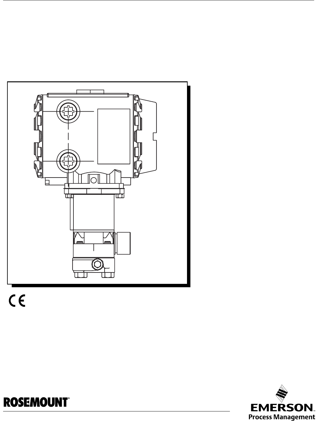
Enclosures The 3095FC is packaged in a NEMA 4 windowed enclosure The enclosure is
fabricated from die-cast aluminum alloy with iridite plating and paint. There
are two ¾-in. pipe threaded holes for field conduit wiring, and
communications.
Mounting Provide adequate clearance for wiring, service, and solar panel. Mount on a
pipestand or to an orifice plate using a 3- or 5-valve manifold. The LCD
display can be rotated 90 degrees in either direction.
For solar-powered 3095FC units orient solar panels as follows:
• Northern Hemisphere: due south (not magnetic south)
• Southern Hemisphere: and due north (not magnetic north)
• Sunlight is not blocked from 9:00 AM to 4:00 PM.
Power Installation
Requirements
The primary power source is provided through DC voltage sources or solar
power. Route power away from hazardous areas, sensitive monitoring
devices, and radio equipment. Adhere to all local, company, and National
Electrical Code (NEC) requirements for power installations.
The 3095FC accepts input voltages from 8.0 volts to 28 volts at the charge
(CHG+ / CHG-) terminals on the termination board. The maximum power for
DC voltage sources is 130 mW, not including battery charging.
An external solar panel connects to the CHG+ / CHG- inputs on the
termination board. Circuitry on the battery charger board monitors and
regulates the charge based on battery voltage, charging voltage, and
temperature. The 3095FC requires a minimum 8-volt 200 mA solar panel.

1-6
Rosemount 3095FC
Reference Manual
00809-0100-4832, Rev AA
October 2004
NOTE:
Do not allow the batteries to fully discharge. If the batteries fully discharge, the
battery charger board may enter thermal limiting.
Rosemount User
Interface Software PC
Requirements
The Rosemount User Interface Software operates on any PC that meets the
following requirements:
• IBM compatible
• Pentium-Class Processor (233 MHz or greater is recommended)
• CD-ROM drive
• Windows 95 (service release B), 98, ME, NT 4.0 (Service Pack 6),
2000 (Service Pack 2), or XP.
•32 MB RAM
• 10 MB of available hard disk space
• RS-232 serial communication
• SVGA color monitor, 800 x 600 pixels
Site Requirements Local, state, and federal codes may restrict monitoring locations and dictate
site requirements. Position the 3095FC to minimize the length of signal and
power wiring.
Wiring Requirements I/O wiring requirements are site and application dependent. Local, state, or
NEC requirements determine the I/O wiring installation methods. Direct burial
cable, conduit and cable, or overhead cables are options for I/O wiring
installations.

Reference Manual
00809-0100-4832, Rev AA
October 2004 Rosemount 3095FC
www.rosemount.com
Section 2 Installation
Mounting . . . . . . . . . . . . . . . . . . . . . . . . . . . . . . . . . . . . . . . page 2-1
Installation . . . . . . . . . . . . . . . . . . . . . . . . . . . . . . . . . . . . . . page 2-2
Wiring . . . . . . . . . . . . . . . . . . . . . . . . . . . . . . . . . . . . . . . . . . page 2-4
Power Supply . . . . . . . . . . . . . . . . . . . . . . . . . . . . . . . . . . . page 2-9
Apply Power . . . . . . . . . . . . . . . . . . . . . . . . . . . . . . . . . . . . page 2-10
Install the Rosemount User Interface Software . . . . . . . . page 2-11
Getting Started with the Software . . . . . . . . . . . . . . . . . . . page 2-12
Establishing Communication . . . . . . . . . . . . . . . . . . . . . . page 2-13
Configuration Tree . . . . . . . . . . . . . . . . . . . . . . . . . . . . . . . page 2-14
MOUNTING Mounting the Rosemount 3095FC can be accomplished using one of the
following methods:
• Pipestand mounted – The Rosemount 3095FC can mount to a 2-in.
pipestand. Ensure that the pipestand meets all weight requirements
and installation conforms to local building codes.
• Orifice Plate – Mount directly to an orifice plate using a 3- or 5-valve
manifold.
With either mounting method, the pressure inputs must be piped to the
process connections.
For solar panel mounting see “Mounting” on page 1-5. Dimensional drawings
are located on page page A-7. Solar power installation is located on page
page 2-3.

Reference Manual
00809-0100-4832, Rev AA
October 2004
Rosemount 3095FC
2-2
INSTALLATION
Rosemount 3095FC Piping from the static and DP meter runs connect to female ¼-18 NPT
connections. The 3095FC is an upstream device, meaning that the SP line
normally connects to the high pressure side (labeled “H” on the sensor body).
Installing the Rosemount 3095FC on a Pipestand
The following steps must be taken to install the 3095FC on a 2-in. pipestand:
1. Install the pipestand using the pipestand documentation.
2. Remove the orifice/meter run from service.
3. Install the 3095FC on a pipestand using clamps or mounting
brackets.
4. Connect the impulse lines.
5. Attach the appropriate wiring (see “Wiring” on page 2-4).
6. Using the prefabricated operator interface cable, physically connect
the 3095FC to the PC running the Rosemount User Interface
Software. One end of the cable (a 9-pin, D-shell, female connector)
plugs into a serial communications port on the PC. The other end of
the cable plugs into the 3095FC.
7. Apply power to the 3095FC (see “Apply Power” on page 2-10)
8. Log into the Rosemount User Interface Software (see page “Log into
the Software” on page 2-12)
9. Establish communication between the 3095FC and PC (see
“Establishing Communication” on page 2-13).
10. Configure the 3095FC (see “Configuration” on page 3-4)
11. Calibrate the 3095FC (see “Calibrate” on page 4-1).
12. Connect the 3095FC unit to any other external communication
devices or networks.
13. Place the meter run in service and monitor with Rosemount User
Interface Software for proper operation.
Installing the 3095FC on an Orifice Plate (Direct Mount)
The following steps must be taken to install the 3095FC on an orifice plate:
1. Remove the orifice/meter run from service.
2. Install the 3095FC on the meter run using a manifold and hardware to
secure the 3095FC to the orifice flanges.
3. Attach the appropriate wiring (see “Wiring” on page 2-4).
4. Using the prefabricated operator interface cable, physically connect
the 3095FC to the PC running the Rosemount User Interface
Software. One end of the cable (a 9-pin, D-shell, female connector)
plugs into a serial communications port on the PC. The other end of
the cable plugs into the 3095FC.
5. Apply power to the 3095FC (see “Apply Power” on page 2-10)
6. Log into the Rosemount User Interface Software (see page “Log into
the Software” on page 2-12)
7. Establish communication between the 3095FC and PC (see
“Establishing Communication” on page 2-13).
8. Configure the 3095FC (see “Configuration” on page 3-4)

Reference Manual
00809-0100-4832, Rev AA
October 2004
2-3
Rosemount 3095FC
9. Calibrate the 3095FC (see “Calibrate” on page 4-1).
10. Connect the 3095FC unit to any other external communication
devices or networks.
11. Place the meter run in service and monitor with Rosemount User
Interface Software for proper operation.
Solar Panels Solar panels generate electrical power for the 3095FC from solar radiation.
They are the optimal choice for locations where a DC voltage source is not
available. The size of solar panels required for a particular installation
depends on several factors, including the power consumption of all devices
connected to the solar array and the geographic location of the installation. An
8-volt solar panel can provide charging power for the backup batteries (see
“Solar Panel Sizing” for information on how to determine the appropriate
panel size required for an application).
An external solar panel typically mounts to the same 2-in. pipe that supports
the 3095FC (see “Mounting” on page 2-1). The panel wiring terminates at the
charge (CHG+ / CHG-) power terminals on the termination board.
NOTE:
Solar panel size may violate certain CSA Class I, Division 1 ratings. Use
approved 3095FC enclosure connectors for routing the power wiring.
The optional solar panel is adequate for support of API Chapter 21.1
compliant measurement and the retrieval of the historical logs once a day
using the internal communication methods.
Solar Panel Sizing
To determine solar panel output requirements, first determine the solar
insolation for the geographic area. The map in Figure 2-1 shows solar
insolation (in hours) for the United States during winter months. Contact an
Emerson Process Management representative for a map detailing a specific
geographic area.
Insolation (from map) = _____ hours
Next, calculate the amount of current required from the solar array per day
using the following equation. ISF is the system current requirement.
Iarray = [ISF (amps) ´ 24 (hrs)]/Insolation (hrs) = _____ amps
Finally, the number of solar panels can be determined using the following
equation:
Number of Panels = Iarray amps/(Ipanel amps/panel) = _____ panels
NOTE:
The “I panel“value varies depending on the type of solar panel installed. Refer
to the vendor's specifications for the solar panel being used.
The current accepted by the Rosemount 3095FC is limited by its charging
circuit to around 1 Amp. Therefore, it is not practical to install a solar array that

Reference Manual
00809-0100-4832, Rev AA
October 2004
Rosemount 3095FC
2-4
supplies significantly more than 1 Amp to the 3095FC. The maximum input is
28 volts.
Do not allow the batteries to fully discharge. If the batteries are fully
discharged, the battery charger board may enter thermal limiting.
Figure 2-1. Solar Insolation in
Hours for the United States
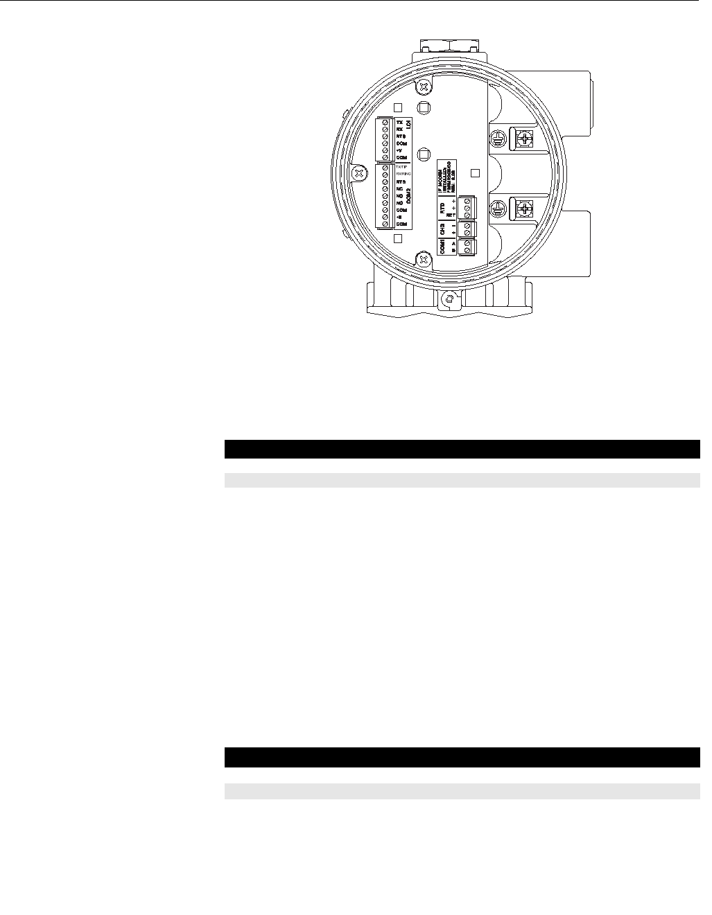
WIRING The field terminals are all located on a Termination Board. The input power
termination (CHG+ / CHG-) uses a removable connector and accommodates
wiring up to 16 AWG in size.
Use the following steps to connect wiring. See Figure 2-2 on page 2-5.
1. Remove power from transmitter (if applicable)
2. Strip the rubber coating from the end (1/4-in. maximum) of the wire.
3. Insert the bared end into the clamp beneath the termination screw. To
prevent short circuits, the inserted wires should have as little bare
wire exposed as possible.To prevent strain, allow some slack when
making connections.
4. Tightening the screw to 0.25 N-m (2.2 lb-in.). Do not over torque the
connector screws.
5. Check the polarity before applying power.
NOTE
To avoid circuit damage, use appropriate electrostatic discharge precautions,
such as wearing a grounded wrist strap.
Reference Manual
00809-0100-4832, Rev AA
October 2004
2-5
Rosemount 3095FC
Figure 2-2. Wiring Terminals
Power Supply Wiring The terminals are labeled CHG+ for positive power connection and CHG- for
negative power connection on a label on the termination board. These
connections provide the input voltage and power for the battery charging
circuitry. The maximum voltage that can be applied to the CHG+ / CHG-
terminals is 28 Volts dc.
RTD Wiring Temperature is input through the Resistance Temperature Detector (RTD)
probe and circuitry. The 3095FC provides terminations for a 2- or 3-wire
100-ohm platinum RTD with a IEC 751 curve. The RTD has an alpha (α)
equal to 0.00385.
The RTD mounts directly to the piping using a thermowell. RTD wires should
be protected by a metal sheath or by a conduit connected to a conduit wiring
fitting on the enclosure. The RTD wires connect to the three screw terminals
designated “RTD” on the Termination Board (see Figure 2-2).
Wiring between the RTD and 3095FC should be shielded wire, with the shield
grounded only at one end to prevent ground loops. Ground loops cause RTD
input signal errors.
Table 2-1 displays the RTD terminal connections for the various RTD probes.
Table 2-1. RTD Signal Routing
Pin Signal Description
1 CHG+ Battery 8.0 to 28 V Power
2CHG– Battery Common
Terminal Designation 3-Wire RTD 2-Wire RTD
RTD + Signal positive input RTD + RTD +
RTD + Signal positive input RTD + Jumper to RTD +
RTD RET Return reference RTD RET RTD RET

Reference Manual
00809-0100-4832, Rev AA
October 2004
Rosemount 3095FC
2-6
Communications Wiring The communication ports located on the 3095FC provide a data link to the
Rosemount User Interface Software, other 3095FC units, and host systems.
NOTE
All communication ports for the 3095FC are located on an optional
communications card or built into the termination board.
Table 2-2. Communication Ports
for the 3095FC
Local Operator Interface Port (LOI)
The Local Operator Interface (LOI) port provides direct communications
between the 3095FC and the serial port of an operator interface device, such
as an IBM compatible PC using an EIA-232 (RS-232) link. The interface
allows access to the 3095FC (using Rosemount User Interface Software) for
configuration and transfer of stored data.
The LOI terminal on the Termination Board provides wiring access to a built-in
EIA-232 (RS-232) serial interface, which is capable of up to 19,200 bps
operation. The operator interface port supports Modbus protocol
communications. The LOI also supports the log-on security feature of the
3095FC if the Security on LOI is Enabled in Rosemount User Interface
Software (“Security Configuration” on page 3-13).
NOTE
By default, the LOI Port is Comm Tag Local Port in the 3095FC > Comm Port
settings screen. Use the 3095FC > Direct Connect command to connect
using the LOI. See “Connection Methods” on page 2-13.
To ease wiring, operator interface cable is available as an accessory (see
“Installation” on page 2-2). Refer to Figure 2-3.
Figure 2-3. Operator Interface
Wiring
Port
3095FC Comm
Port Location Default Tag Function/Type
1 CPU RJ-45 (top) Local Port LOI / RS-232D
2CPU RJ-45 (top) COMM1 Ethernet
3 CPU 5-pin (bottom) COMM2 Serial / EIA-232 (RS-232)
4Module Slot 1 COMM3 EIA-232 (RS-232), EIA-485
(RS-485), Modem, or MVS
5Module Slot 2 COMM4 EIA-232 (RS-232), EIA-485
(RS-485), Modem, or MVS
6Module Slot 3 COMM5 EIA-232 (RS-232), EIA-485
(RS-485), Modem, or MVS
1
6
7
8
9
2
3
4
5
To screw
Terminals
Connection at
PC COM Port
White TX
Red TX
Black TX

Reference Manual
00809-0100-4832, Rev AA
October 2004
2-7
Rosemount 3095FC
Table 2-3. Local Operator
Interface Port Wiring
Table 2-4. PC Comm Port
Wiring
EIA-485 (RS-485) Serial Communications - Comm 1
Use Comm 1 to monitor or alter the 3095FC from a remote site using a host or
Rosemount User Interface Software. Comm 1 supports baud rates up to
19200 bps. Comm 1 also supports the log-on security feature of the 3095FC if
the Security on Comm 1 is Enabled in Rosemount User Interface Software.
Comm 1 sends and receives messages using Modbus protocol. Comm 1
permits EIA-485 (RS-485) serial communication protocols that meet EIA-485
(RS-485) specifications for differential, asynchronous transmission of data
over distances of up to 1220 m (4000 ft). The EIA-485 (RS-485) drivers are
designed for true multi-point applications with multiple devices on a single bus.
The default values for the EIA-485 (RS-485) communications are: 9600 Baud
Rate, 8 Data Bits, 1 Stop Bit, No Parity, 10 millisecond Key On Delay, and 10
millisecond Key Off Delay. The maximum baud rate is 19200 bps. To enable or
disable the Comm 1 port, select Configure > Radio Power Control and select
the Enable (default)/Disable under Radio Power Control (see “Radio Power
Control Configuration” on page 3-23).
Wiring should be twisted-pair cable. The terminals and their functions are as
follows:
Table 2-5. EIA-485 (RS-485)
Communications Wiring
EIA-232 (RS-232) Communications - Comm 2
A EIA-232 (RS-232) communications card in the Comm 2 port can switch
power to an external communication devices, such as a radio, to conserve
power. A label on the termination board denotes the usage of each pin on the
connector.
The EIA-232 communications card meets all EIA-232 specifications for
single-ended RS-232 asynchronous data transmission over distances of up to
15 m (50 ft). The EIA-232 (RS-232) communications card defaults are: 9600
baud rate, 8 data bits, 1 stop bit, no parity, 10 millisecond Key On Delay, and
10 millisecond Key Off Delay. The maximum baud rate is 19200 bps. Refer to
Table 2-6 for communication card signals.
Signal Label
Common COM
LOI Power(1)
(1) Do not use the LOI to power external devices.
TX + V
Common COM
Ready to Send RTS
Receive (RX) RX
Transmit (TX) TX
Signal Pin Label
Transmit (TX) 2 TX
Receive (RX) 3RX
Ground (GND) 5 COM
Pin Function Label
1 RS-485 B
2 RS-485 A

Reference Manual
00809-0100-4832, Rev AA
October 2004
Rosemount 3095FC
2-8
Table 2-6. Communications
Card Signals
Table 2-7. EIA-232 (RS-232)
Communications Card Wiring
Ground the Transmitter Grounding reduces the effects of electrical noise on the unit's operation and
protects against lightening. The 3095FC provides lightening protection for
built-in field wiring inputs and outputs. Install a surge protection device on the
DC voltage source system to protect the device against lightning and power
surges.
The 3095FC has two grounding screws inside the enclosure. It is
recommended that a minimum of 14 AWG wire be used for the ground wiring.
To minimize signal errors caused by EMI (electromagnetic interference), RFI
(radio frequency interference), and transients, The I/O signal wiring cable
should be an insulated, shielded, twisted-pair. All grounds should terminate at
a single point.
NOTE
Grounding wiring requirements for DC voltage sources equipment are
governed by the National Electrical Code (NEC). When the equipment uses
DC voltage sources, the grounding system must terminate at the service
disconnect. All equipment grounding conductors must provide an
uninterrupted electrical path to the service disconnect.
Earth Grounds
All earth grounds must have an earth to ground rod or grid impedance of 25
ohms or less as measured with a ground system tester. The grounding
conductor should have a resistance of 1 ohm or less between the 3095FC
enclosure ground and the earth ground rod or grid.
Pipelines With Cathodic Protection
The 3095FC must be electrically isolated from the pipeline. Electrical isolation
can be accomplished by using insulating flanges upstream and downstream
on the meter run. In this case, the Rosemount 3095FC could be flange
mounted or saddle-clamp mounted directly on the meter run and grounded
with a ground rod or grid system (see “Earth Grounds” on page 2-8).
Signals Action
RTS The request to send signals that the modem is ready to transmit.
RX The RXD receive data signals that data is being received at the
communications card.
TX The TXD transmit data signals that data is being transmitted from
the communications card.
Signal Label
Signal Common Negative COM(1)
(1) GND at Pin 1 and Pin 3 are identical. They are separated for ease of wiring.
Switched Power TX(2) + B
(2) Switched Power is used with an internal radio or cell phone. It does not power external devices.
Ground COM(1)
Request to Send RTS
Tip / Receive Data RX
Ring / Transmit Data TX(3)
(3) Transmit (TX) connects to the 3095FC unit's receive.

Reference Manual
00809-0100-4832, Rev AA
October 2004
2-9
Rosemount 3095FC
Pipelines Without Cathodic Protection
The pipeline may provide an adequate earth ground and the 3095FC could
mount directly on the meter run using an orifice plate. Use a ground system
tester to make sure the pipeline to earth impedance is less than 2 ohms. If the
pipeline to earth impedance is greater than 2 ohms, the 3095FC installation
should be electrically isolated and a ground rod or grid grounding system
installed. If the pipeline provides an adequate ground, a separate ground rod
or grid system may not need to be installed.
POWER SUPPLY The 3095FC accepts input voltages from 8.0 volts to 28 volts at the power
terminals (CHG+ / CHG-) with no external current limiting (internal current
limit is 200 mA). The CHG+ / CHG- terminal can accommodate up to 16 AWG
wire.
To adequately meet the needs of the 3095FC system, it is important to
determine the total power consumption and size of solar panel requirements
accordingly. To determine the total 3095FC power consumption, be sure to
add the power consumption (in mW) of any other devices used with the
3095FC in the same power system. The maximum power for DC voltage
sources is 130 mW not including the battery charging.
Convert the total value (in mW) to Watts by dividing it by 1000.
mW / 1000 = Watts
For selecting an adequate power supply, use a safety factor (SF) of 1.25 to
account for losses and other variables not factored into the power
consumption calculations. To incorporate the safety factor, multiply the total
power consumption (P) by 1.25.
PSF = P x 1.25 = _____ Watts
To convert PSF to current consumption in amps (ISF), divide PSF by the
system voltage (V) of 12 volts.
ISF = PSF / 12V = _____ Amps
Batteries
Batteries provide power for the 3095FC when the solar panels are not
generating sufficient output. The batteries are three D-size lead-acid batteries
providing 2.5 Amp-hours of current at 6.2 volts.
The batteries are connected in series by the Battery Charger Board to
achieve the required capacity. The battery capacity determines the number of
days of reserve (autonomy) desired.
When the 3095FC is configured as an API compliant Electric Flow
Management (EFM) and requires an internal communications card, a solar
panel, and the internal batteries, the 3095FC should be able to communicate
the API audit trail information once a day to a remote host using no additional
battery source, no additional solar panel, and maintain a 13 day autonomy in
the event that the solar panel is lost.
To determine the system capacity requirements, multiply the system current
load (ISF) on the batteries by the amount of reserve time required. Compute
“ISF” as described above. The equation is as follows:
System Requirement = ISF amps x Reserve hrs = _____ amp-hrs

Reference Manual
00809-0100-4832, Rev AA
October 2004
2-10
Rosemount 3095FC
APPLY POWER To prevent unnecessary battery drainage, the 3095FC is delivered with the
reset jumper in the OFF position. To apply power to the 3095FC:
1. Complete the necessary wiring (“Wiring” on page 2-4).
1. Unscrew the front end cap cover (LCD end).
2. Place the power jumper in the ON position. The jumper is located on
the LCD (if installed) or at J1 on the Battery Charger Board.
3. Screw the front-end cap cover (LCD end).
After the 3095FC completes start-up diagnostics (RAM and other internal
checks), the optional LCD displays the date and time to indicate that the
3095FC completed a valid reset sequence. If the LCD does not come on,
refer to Section 5: Troubleshooting and Maintenance.

Reference Manual
00809-0100-4832, Rev AA
October 2004
2-11
Rosemount 3095FC
INSTALL THE
ROSEMOUNT USER
INTERFACE SOFTWARE
If a previous version of the Rosemount User Interface Software is installed,
refer to “Uninstalling the Rosemount User Interface Software” on page 2-12.
Software Overview
The Rosemount User Interface Software is used to configure the 3095FC. For
PC requirements see “I/O wiring requirements are site and application
dependent. Local, state, or NEC requirements determine the I/O wiring
installation methods. Direct burial cable, conduit and cable, or overhead
cables are options for I/O wiring installations.” on page 1-6.
The major components of the Rosemount User Interface Software user
interface are:
• Menu bar and menus
• Function screens
• Dialog boxes
• Help system, including the Status bar and message boxes
The menu bar appears on the screen after successfully logging on. From the
menu bar, the user may activate a menu and select a function in that menu.
Functions may be selected using Toolbar Buttons or the Configuration Tree
Menu
Several buttons are commonly used on many Rosemount User Interface
Software screens.These buttons are:
• Update: updates content of the window.
• OK: approves and closes the window. A Confirm Save dialog box
appears if there are unsaved changes.
• Cancel: cancels all changes and closes the window.
• Apply: applies changes to the window.
Install With Autorun 1. Insert the Rosemount User Interface Software installation CD-ROM
into the drive
2. Click Next.
3. Click Yes to agree with the Terms and Conditions
4. Enter the users Name and the Company name. Click Next.
5. The software is saved to the default directory
C:\Program Files\Rosemount\Rosemount 3095FC User
Interface\User Interface. If another location is desired, use to Browse
button to select that location. Click Next. A warning box appears if
there are incompatible files.
6. Review the items in the list and click Next.
7. When the installation is complete click Finish.
8. Remove the Rosemount User Interface Software installation
CD-ROM.

Reference Manual
00809-0100-4832, Rev AA
October 2004
2-12
Rosemount 3095FC
Install Without Autorun 1. Insert the Rosemount User Interface Software installation CD-ROM.
2. Click the Windows Start button.
3. Select Run.
4. Click the Browse button
5. Navigate to and select the Select.exe located on the CD-ROM.
6. Click OK in the Navigation Window.
7. Click OK in the Run window.
8. Continue with in “Install With Autorun" steps 2-8, located above.
Uninstalling the
Rosemount User
Interface Software
1. Click the Windows Start button.
2. Select Settings > Control Panel.
3. Double-click the Add/Remove Programs icon.
4. Select Rosemount 3095FC User Interface.
5. Click Change/Remove.
6. Follow the instructions that appear on the screen.
GETTING STARTED
WITH THE SOFTWARE
Run the Software To run the software, perform one of the following steps
• Double-click on 3095FC User Interface located on the desktop.
• Select Start > Programs > Rosemount 3095FC User Interface >
3095FC User Interface.
• Double-click on the file 3095.exe located in C:\Program
Files\Rosemount\Rosemount 3095FC User Interface (default
directory). If the program file was saved to another location in “Install
With Autorun” on page 2-11, select this location instead.
NOTE
Only one version of Rosemount User Interface Software can run at a time.
Log into the Software To log on to Rosemount User Interface for Windows software:
1. Connect the 3095FC to the Local Operator Interface (LOI) port and
launch Rosemount User Interface Software.
2. Enter the factory-assigned 3-character login (username): LOI.
Enter the 4-digit password: 1000. The login is assigned using the
security feature of the Rosemount User Interface Software (see
“Security Configuration” on page 3-13).
NOTE
Login is case sensitive.
If the login is not valid, a dialog box appears. Click OK and reenter the login
and password. Repeat this procedure until a successful login and password is
entered. To exit the login screen press >Esc> or click Cancel.
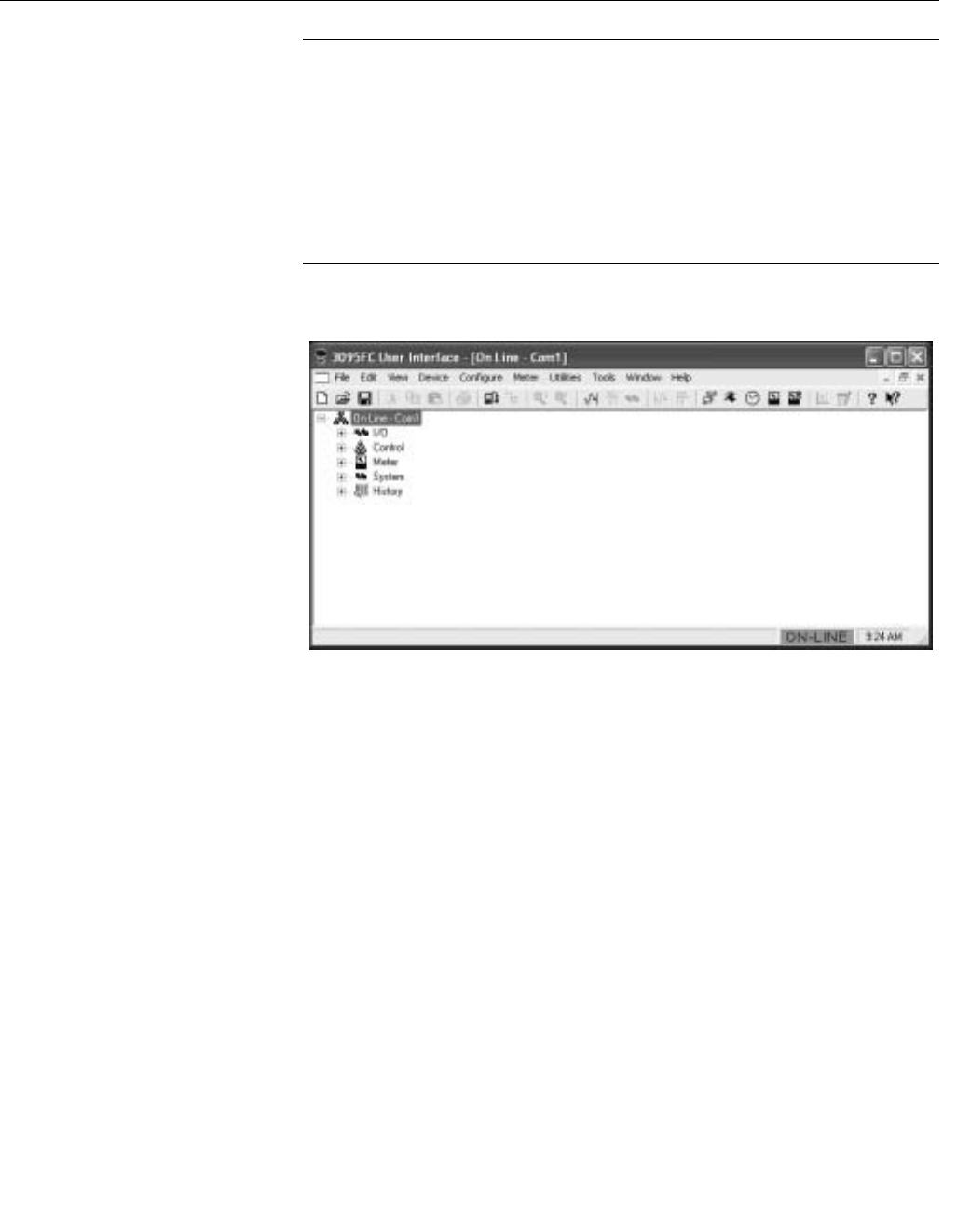
When login is successful, the Configuration Tree appears on the screen. See
“Configuration Tree” on page 2-14 for more information.

Reference Manual
00809-0100-4832, Rev AA
October 2004
2-13
Rosemount 3095FC
ESTABLISHING
COMMUNICATION
Connection Methods When the user is logged into the Rosemount User Interface Software, the PC
must connect to the 3095FC unit so communication can be accomplished.
Use one of the following connection methods:
• Direct Connect - Connect to the 3095FC using the Local Port (LOI) if
the default communication parameters apply.
• 3095FC (Communications) Directory View - Double-click the Station
Name to connect to the 3095FC using the parameters currently set for
that 3095FC.
NOTE
Once connected, the Configuration Tree view becomes the active screen.
Direct Connect
The Direct Connect command allows the Rosemount User Interface Software
to initiate communications with the 3095FC by performing a search of the PC
communication ports at various baud rates. Direct Connect “locks on” to the
first Comm Port and Baud Rate (1200, 2400, 4800, 9600, 19200, 38400, and
57600 bps) that successfully communicate with a 3095FC.
If unsuccessful, the program attempts to establish communications through
the remaining COM Ports of the PC, successively, until it receives a valid
reply.
For the Direct Connect option to operate correctly the PC must be connected
to the Local Operator (LOI) port of the 3095FC with communication settings
of:
• 8 Data Bits
• 1 Stop Bit
•No Parity
To use Direct Connect:
1. Physically connect the 3095FC (see “Installation” on page 2-2).
2. Launch and log into Rosemount User Interface Software (see
“Getting Started with the Software” on page 2-12).
3. Perform one of the following:
• Click on the Direct Connect icon in 3095FC Directory
(Configuration Tree.)
• Click the Direct Connect button on the toolbar.
4. If this is the first time connecting to the 3095FC, continue with
“Setting the Clock” on page 3-4.

Reference Manual
00809-0100-4832, Rev AA
October 2004
2-14
Rosemount 3095FC
Connect
When off-line, the 3095FC menu displays Connect. To use Connect:
1. Physically connect the 3095FC (see “Installation” on page 2-2).
2. Launch and log into Rosemount User Interface Software (see
“Getting Started with the Software” on page 2-12).
3. Perform one of the following:
• Select a communications port from the Device Directory and press
the <Enter> key.
• Double-click on a communications port from the Device Directory.
• Click the Connect button on the toolbar.
• Select Device > Connect to connect to the 3095FC currently
selected in the Device Directory. If a 3095FC is not currently
selected, the error “No 3095FC is Currently Selected” appears.
Remote Hardware Connection
To connect the PC to a remote 3095FC, a serial, dial-up modem, radio,
satellite, or other communications line should be installed. This connection is
typically made through the host port on the 3095FC. Use the Connect
command to connect to a serial or dial-up modem
Disconnect from the 3095FC
Close the screen to disconnect an on-line connection. This automatically
closes the connection.
CONFIGURATION TREE When communication is established with a 3095FC or opening a
configuration file, the Configuration Tree appears on the screen. The
Configuration Tree is used to perform the following:
• Add, delete, or modify communication configurations for the 3095FC
units. The communication configurations allow the Rosemount User
Interface Software to communicate to an individual 3095FC unit.
• Establish Groups of 3095FC units. A 3095FC Group is typically several
units in the same geographical area or a number of units with
something else in common. Each group contains a list of all the
3095FC devices contained within that group.
• Assign an address for every 3095FC within a group. Each 3095FC has
a Station Name (Tag) and unique address with which to differentiate
each device. The Address must be different from any other host system
that may access the communications link.
• Setup the 3095FC Comm Ports
Use the “+” and “–” symbols to display or hide various options.
Toggle between the Online configuration screen and the Configuration
tree/device directory using Window > >select file>.
Reference Manual
00809-0100-4832, Rev AA
October 2004
2-15
Rosemount 3095FC
NOTE
Double-click the desired communications link (3095FC name) to connect to
that 3095FC. Double-clicking an icon is the same as selecting the menu bar
or toolbar button Direct Connect or Connect commands.
Configuration of the PC Communication Ports to the 3095FC unit cannot be
performed within the 3095FC unit configuration screen. Return to the 3095FC
Directory (Configuration Tree) screen. If the user is in a configuration, select
Window > Device Directory or View > Device Directory to view the 3095FC
directory.
Figure 2-4. Configuration Tree
Screen
Adding a Group
Multiple 3095FC units can be organized to form Groups. Unit Groups are
typically units in the same geographical area or units with something else in
common. When a Group file is selected, a list of all 3095FC communication
setups in the Group appears below the Group.
1. Right-mouse click on the Device Root directory icon.
2. Select Add a Group.
3. Right-mouse click on the New Group and select Rename. Type in the
new Group name.
4. Press <Enter>.
5. The 3095FC can now be added to the Group.
Deleting a Group
1. Right-mouse click on the group to be deleted.
2. Select Delete Group.
3. Click Yes.

Reference Manual
00809-0100-4832, Rev AA
October 2004
2-16
Rosemount 3095FC
Adding a 3095FC transmitter
1. Right-mouse click on the Device Root directory icon.
2. Select Add a Device .
3. Right-mouse click on the New Device and select Rename. Type in the
new device name.
4. Press <Enter>.
5. Configure the 3095FC communication parameters.
NOTE
Place a 3095FC connection under a Group by selecting the Group before
adding the 3095FC Connection.
Deleting a 3095FC transmitter
1. Right-mouse click on the device to be deleted.
2. Select Delete Device.
3. Click Yes.
Deleting all 3095FC transmitters
1. Right-mouse click on the Device Root directory icon.
2. Select Delete All Devices.
3. Click Yes in the Confirm Delete Message dialog box.
Renaming a Group or 3095FC
1. Right click on the Device or Group to be renamed.
2. Select Rename.
3. Type the new name.
4. Press <Enter>.

Reference Manual
00809-0100-4832, Rev AA
October 2004 Rosemount 3095FC
www.rosemount.com
Section 3 Configuration
Overview . . . . . . . . . . . . . . . . . . . . . . . . . . . . . . . . . . . . . . . page 3-1
Basic Functions . . . . . . . . . . . . . . . . . . . . . . . . . . . . . . . . . page 3-1
Configuration . . . . . . . . . . . . . . . . . . . . . . . . . . . . . . . . . . . page 3-4
Custom Displays . . . . . . . . . . . . . . . . . . . . . . . . . . . . . . . . . page 3-54
OVERVIEW The Rosemount 3095FC has parameters that must be configured before it is
calibrated and placed into operation. Configuration must be performed using
Rosemount User Interface Software. Configuration can be performed either
onsite using the LOI port or off-line and later loaded into the unit.
Default values for all parameters exist in the firmware of the 3095FC. The
following parameters should be verified and configured:
• “Setting the Clock” on page 3-4
• “Configuring the System Flags” on page 3-5
• “3095FC Communications Ports Configuration” on page 3-8
• “Security Configuration” on page 3-13
• “LCD User List Configuration” on page 3-15
• “Analog Input (AI) Configuration” on page 3-16
• “Meter Run Configuration” on page 3-25 and “Gas Quality Tab” on
page 3-28.
• “History Points Configuration” on page 3-32
BASIC FUNCTIONS Begin the configuration process with “Setting the Clock” on page 3-4.
The following functions are used throughout the configuration process. They
are provided at the beginning of the section so they can be easily referenced.
Select TLP Options
Throughout Rosemount User Interface Software, the Select TLP dialog can
be accessed by clicking the browse button with three dots. The Select TLP
dialog allows the user to assign specific inputs and outputs to parameters.
Rosemount User Interface Software uses Point Type (T), Logical Number (L),
and Parameter (P) to define point locations.
The display field at the bottom of the Select TLP dialog displays the numeric
point location of the TLP point or a text abbreviation, depending on the
Display setting (see “Display TLP Options").
Display TLP Options
Select Tools > Options to set whether the TLP displays as text or numbers in
TLP display fields throughout the Rosemount User Interface Software.

Reference Manual
00809-0100-4832, Rev AA
October 2004
Rosemount 3095FC
3-2
Duplicating a Configuration
Duplicate the configuration of a 3095FC using these instruction.
1. File > Save Configuration to save the configuration to a specified file.
2. Establish Communications with the second unit (see page 2-13).
3. File > Download loads the configuration into the unit.
4. After loading the configuration data into the second 3095FC (Step 3),
save the configuration to a unique disk file by repeating Step 1.
Using Copy and Paste
Use Copy and Paste to copy data from one configuration screen to another of
the same type.
1. Configure the point that is to be duplicated.
2. Click Apply.
3. Click Copy.
4. Select the next Point Number or go to the appropriate screen.
5. Click Paste.
6. Click Update.
New Configuration File
Create a configuration file off-line using the following instructions.
1. Select File > New.
2. The Type parameter indicates the type of 3095FC unit.
3. The number of orifice meters will be 1.
4. Save the configuration file.
5. Establish an on-line connection to the 3095FC unit.
6. Configure as necessary.
Open File
The Open option opens an existing configuration file. Configuration files are
created using the Save Configuration function. To open a configuration file:
1. Establish an on-line connection to the 3095FC (see “Establishing
Communication” on page 2-13).
2. Select File > Open.
3. Select the configuration file name. The extension must be .800.
4. Configure as necessary.
Once the configuration file is opened it automatically becomes active and may
be edited offline. The configuration file may also be loaded into a 3095FC
using the “Download File" function (see page 3-3).
Save File
The Save option saves the current configuration of a connected 3095FC to a
disk file. Once a backup configuration file is created it can be loaded into a
3095FC using the “Download File" function (see page 3-3).
1. Select File > Save Configuration. The Save As dialog box appears.
2. Type the desired File name of the backup file or use the default.
3. Click Save. The file is saved in the default directory C:\Program
Files\Rosemount\Rosemount 3095FC User Interface\User Interface
unless another directory was selected.

Reference Manual
00809-0100-4832, Rev AA
October 2004
3-3
Rosemount 3095FC
Download File
Use this function to download a previously saved configuration to a 3095FC.
Configuration files are created using the Save Configuration function. To
download a previously saved configuration:
1. Select File > Download.
2. Select the configuration file name with the extension .FCF
3. Click Open.
4. Select the Point Types to download. Use Select All or Deselect All to
change multiple Point Types. Select or Deselect individual Point
Types by selecting the configuration Point Type in the left column and
selecting specific Point Types in the right column.
NOTE
The Configuration Points screen changes depending on the type of device
that is connected.
5. Select only the Configuration Points to download.
6. Click Download. Downloading automatically begins.
7. Click OK when the download is complete.
Print Configuration
The Print Configuration option enable specifying Point Types to Print.
1. Select File > Print Configuration.
2. Select the Point Types to be printed. Select the All or Deselect All
buttons for multiple Point Types or select/deselect individual Point
Types by using the mouse to double click on the Point Type in the left
column and selecting specific Parameters in the right column.
3. Click OK.
4. When the Print Preview screen appears, choose one of the following
buttons:
• Print to send to a local printer.
• PDF to create a .pdf (Portable Document File).
• Excel to create an .xls spreadsheet file.
• RTF to create an .rtf (Rich Text Format) file.
• HTML to create an .htm Internet browser file.
• TXT to create a .txt text file.
5. The 3095FC Group, Address, Field, and Value information displays in
the Print Configuration results window.
Reference Manual
00809-0100-4832, Rev AA
October 2004
Rosemount 3095FC
3-4
CONFIGURATION
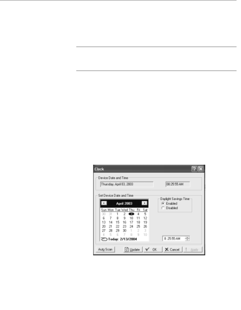
Setting the Clock Immediately after connecting to a 3095FC for the first time, set the
Rosemount User Interface Software Clock to ensure proper logging of history.
The internal real-time clock provides time-stamping and control of the
historical databases, Event Log, Alarm Log, Audit Log, and Contract Hour.
NOTE
The time stamp reflects the time at the end of the period. Data collected from
0800 to 0900 is thus time-stamped 0900. This is used for the logging of
history.
See Figure 3-1
1. Select Device > Clock or click the Clock icon in the toolbar.
2. The display at the bottom of the calendar is the date and time from
the PC clock. Continue with Step 5 if correct.
3. If it is not correct:
a. use the arrow buttons to select the correct Month and Year
b. click on the desired day of the month
c. click on the time field and type in the desired value (type A or P for
the AM/PM field) or use the arrows.
4. The clock can automatically compensate for daylight savings time by
enabling this feature.
5. Click Apply and click OK.
Figure 3-1. Clock Screen

Reference Manual
00809-0100-4832, Rev AA
October 2004
3-5
Rosemount 3095FC
Configuring the System
Flags
Use System Flags to perform actions that affect the overall operation of the
3095FC. From the Flags screen, a configuration can be saved to Flash
memory and the 3095FC can be re-initialized.
NOTE
Certain Flags cause data to be lost, parameter values to be changed, and
configuration memory to be cleared. Confirm Flag function before changing.
General Tab
Figure 3-2 on page 3-6
After a Warm Start, the 3095FC is initialized from SRAM memory if the
configuration is valid. If valid, the databases remain intact. If the memory does
not have a valid configuration, the configuration that was last saved to Flash
memory is used. To save a valid configuration, use the Save Configuration
button.
In a Cold Start, the 3095FC is initialized from the restart configuration saved in
the Flash memory. If the configuration memory does not have a valid
configuration written in it, the factory defaults are used.
NOTE
Perform a Cold Start after setting the clock and BEFORE setting any other
parameters to ensure the 3095FC memory is cleared before configuration
begins.
Cold Start reloads all restart configuration data and may also clear logs and
displays. In addition, it may cause output changes, load new accumulator
values, and disable user program tasks and User Data Types. Generally, a
Cold Start should not be used on a 3095FC that is actively gathering data or
performing control. Save or document all required data and parameter values
that could be affected before performing the Cold Start.
The following may occur when performing a Cold Start:
• Cold Start restores a configuration from default values stored in Flash
memory.
• Cold Start & Clear ALL restores a configuration from default values
stored in Flash memory and clears all History, Alarm Log/Event Log,
and displays.
• Cold Start & Clear Alarms/Events restores a configuration from default
values stored in Flash memory and clears the Alarm Log/Event Log.
• Cold Start & Clear Displays restores a configuration from default values
stored in Flash memory and clears the 3095FC Displays.
• Cold Start & Clear History Data restores a configuration from default
values stored in Flash memory and clears all History database files.
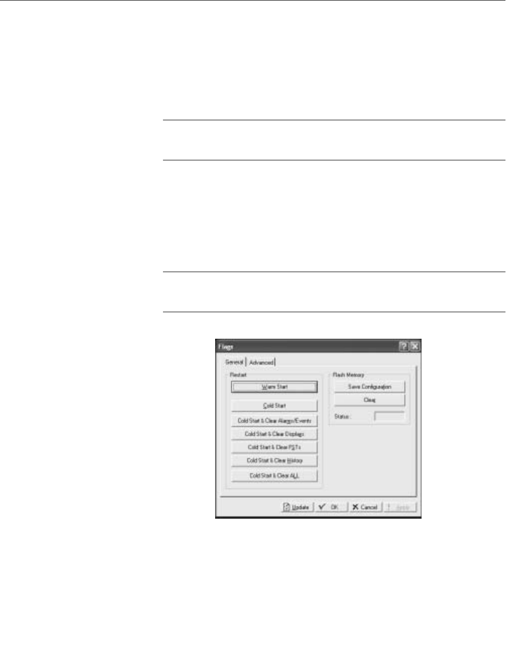
Reference Manual
00809-0100-4832, Rev AA
October 2004
Rosemount 3095FC
3-6
The Clear Flash Memory procedure clears all saved restart configuration data
contained in Flash memory. Only factory defaults are retained. To return the
3095FC to the original factory default settings:
1. Select Device > Flags > General Tab
2. Select the Clear button and click Yes.
3. Perform a Cold Start using the Cold Start & Clear ALL button.
4. Click Yes, Apply, and OK.
NOTE
The Status field displays the current status of the save or clear flash memory
function.
To save configuration settings to Flash memory, use the Flash Memory Save
Configuration function in the 3095FC Flags screen. It is possible to backup
the working configuration from SRAM to Flash memory. In the event of
operating problems, the working configuration can be restored by performing
a Cold Start. To save the current configuration to Flash memory:
1. Select Device > Flags.
2. Select Save Configuration. Click Yes, Apply, and OK.
NOTE
Depending on the communications type and speed, the user may have to
reconnect to the 3095FC after this procedure.
Figure 3-2. 3095FC System
Flags General Tab
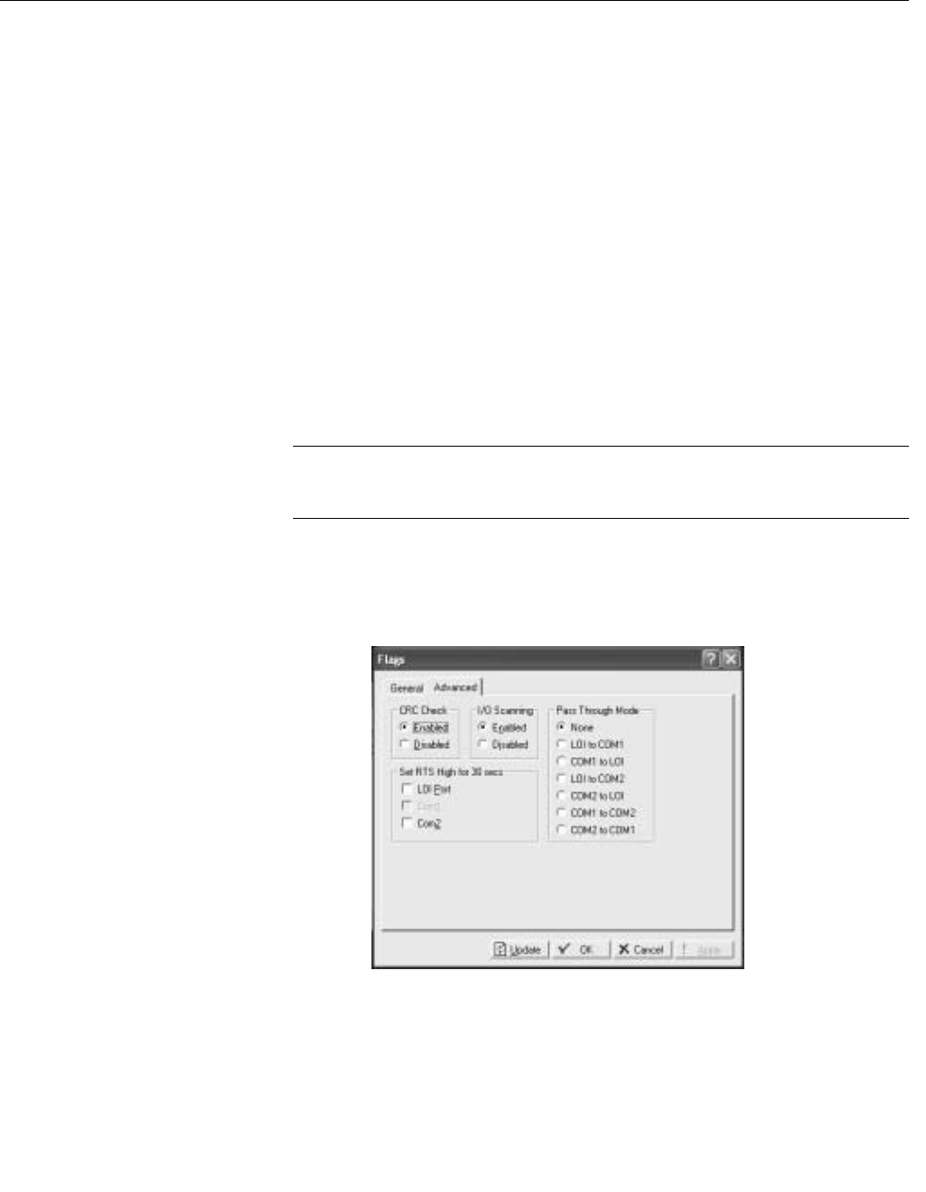
Reference Manual
00809-0100-4832, Rev AA
October 2004
3-7
Rosemount 3095FC
Advanced Tab
Use the following instructions to configure the Advanced System Flags tab.
See Figure 3-3.
1. Select Device > Flags > Advanced Tab.
2. Enable CRC Check to perform CRC (Cyclical Redundancy Check)
check on 3095FC protocol communications.
3. Enable I/O Scanning so the I/O is in normal scan mode. When
Disabled, all I/O scanning stops and the last values are used until
scanning is resumed.
4. Select a Pass Through Mode communications option to send Pass
Through messages. Using any of the communications ports, Pass
Through Mode allows data to be received by one unit and then
passed through to other devices connected on any other
communications port. For example, the host communicates using a
radio on its LOI port. Other 3095FC units can then be connected to
the EIA-485 (RS-485) port of the first unit. All units can use the one
radio to communicate to the host.
NOTE
COM2 may only use a Dial-up modem if it is receiving Pass Through
messages. It cannot transmit to other field devices via Dial-up modem.
5. Select the respective port (LOI, COM 1, or COM 2) for the Set RTS to
High for 30 Sec option and click Apply to activate the RTS
(Request-to-Send) signal. The RTS signal turns on for 30 seconds.
Figure 3-3. 3095FC System
Flags Advanced Tab
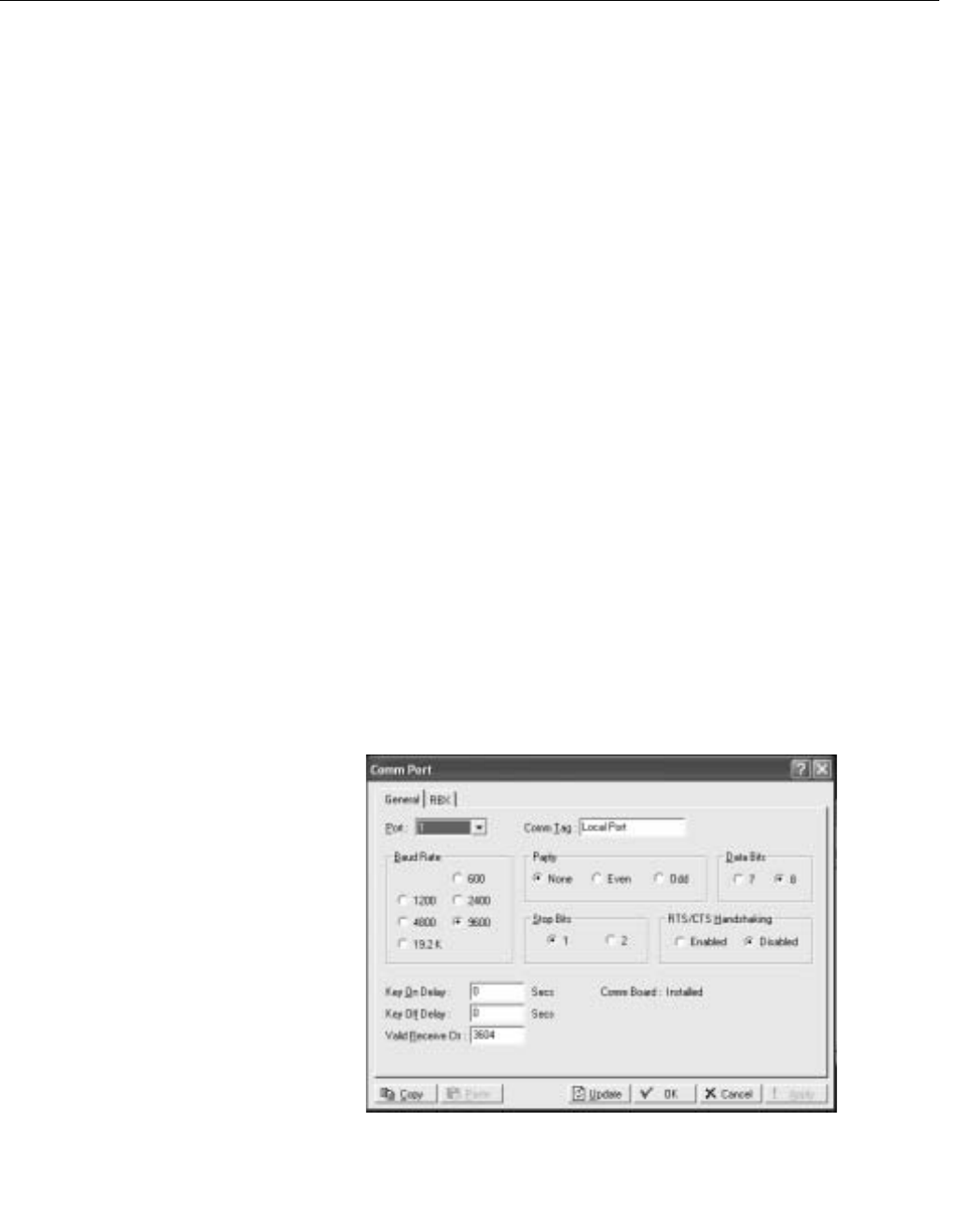
Reference Manual
00809-0100-4832, Rev AA
October 2004
Rosemount 3095FC
3-8
3095FC Communications
Ports Configuration
The communication ports of the 3095FC provide a link to a PC, such as one
running Rosemount User Interface Software or a host PC. The 3095FC can
have up to three communication ports.
General Tab
See Figure 3-4.
1. Select Device > Comm Ports > General Tab
1. Select the Port that the 3095FC is using to communicate. Enter the
10-character Comm Tag name for identification of the
communications port.
2. Select the transmit and receive data Baud Rate in bits per second.
3. Select the Parity radio button if checks are to be performed by the
communications controller.
4. Select the number of Data Bits contained in an asynchronous byte, or
character. This number is typically 8.
5. Select the number of Stop Bits contained in an asynchronous byte, or
character. This number is typically 1.
6. Select if the RTS/CTS Handshaking is enabled.
7. Enter the Key On Delay to define the number of seconds to delay
after turning the RTS signal on before beginning transmission. For
older radios, the Key On Delay may need to be set as high as 0.2
seconds. For radios designed for data transmission, no more than
0.02 second should be required.
8. Enter the Key Off Delay intervals defining the period to delay before
turning the RTS signal off once a valid message has been sent. The
default of 0.01 seconds should be sufficient for most radios.
9. Enter the Valid Receive Ctc (Counter) to log the number of valid
OpCodes received by the device on the communication port. The
value in the counter can be preset or cleared.
Figure 3-4. Device Comm Port
General Tab Screen

Reference Manual
00809-0100-4832, Rev AA
October 2004
3-9
Rosemount 3095FC
RBX Tab
To configure the RBX, a modem must be present and appropriately
configured. Use the following steps to configure the RBX tab.
See Figure 3-5 on page 3-10.
1. Configure the Device > Comm Ports > General Tab (see “General
Tab” on page 3-8).
2. Select Device > Comm Ports > RBX Tab.
3. Enable RBX Mode. The RBX (Report-by-Exception) feature allows
the 3095FC to call in to a host PC when a configured alarm occurs.
4. Enter the RBX Host Address and Group number. The defaults of “1”
and “0” are used by most host driver software.
5. Set the Delay to define the time, in seconds, between attempts to
transmit an RBX message. There is a Delay parameter associated
with each Retry Count parameter, allowing the user to identify
different length delays for each entry.
6. The RBX Attempts #1 - 3 (Retry Count) is the number of attempts a
message is repeated if a valid response is not obtained on the first
attempt. Attempts include the initial message plus the retries. The
three Retry Count parameters each have an associated Delay
parameter. Selecting Fixed Number allows the user to enter a value
for how many times a message is retried after the first unsuccessful
attempt. Note that a “0” entry causes no retries. Selecting Continuous
causes continuous retries that can only be stopped when the host
clears the RBX alarm.
For example: If setting the Retry Count #1 to “2”, Delay #1 to “10”,
Retry Count #2 to “1” and Delay #2 to “20”, then after the first
unsuccessful attempt to communicate with the host, the 3095FC tries
two more times after waiting 10 seconds each time, and once more
after waiting 20 seconds.
7. Enabling the Extra Key On Delay to add an additional amount of time
to delay transmitting an RBX message after turning the RTS signal
on. The amount of time is fixed. This parameter is used for radio
communications.
8. RBX ACK Timeout - This is a message from the Device. If the ACK
fails to be received within the timeout period the 3095FC retries the
RBX.
NOTE
The RBX Alarm Index indicates alarms currently being reported through the
RBX. The RBX Status parameter indicates the status of RBX messaging,
either Active or Inactive. Active indicates that an SRBX alarm is being
processed.
9. After configuring the RBX function, use Device > Flags > Flash
Memory Save Configuration to save the configuration to the Flash
Memory in case a Cold Start must be performed.
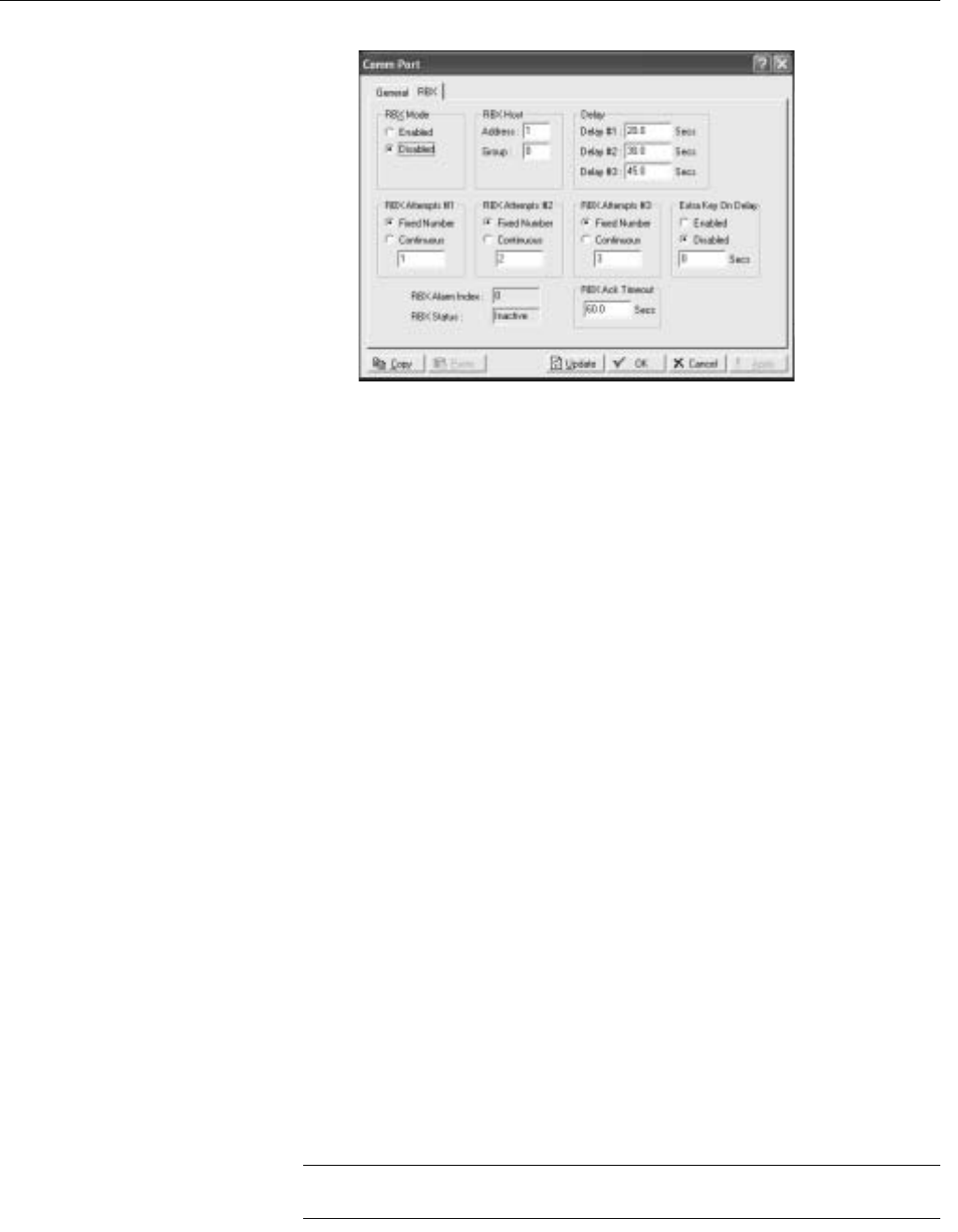
Reference Manual
00809-0100-4832, Rev AA
October 2004
Rosemount 3095FC
3-10
Figure 3-5. Device Comm Port
RBX Tab Screen
3095FC Device
Configuration /
Information
This step establishes the Station Name, Address, Group, and other global
variables that differentiate a 3095FC. Other system variables set in the
information screen must be established for a particular application.
General Tab
See Figure 3-6 on page 3-11.
Use the following instructions to configure the Device Information General
tab.
1. Select Device > Information > General Tab.
2. Enter the Station Name to be logged with the historical database for
site identification.
3. Enter a unique Address to differentiate each device in a
communications group. The Address can be assigned a value from 1
to 255. The System Default Address of 240 should not be used.
4. Enter a Group to identify a set of 3095FC units for communication
purposes, typically to a host that polls the 3095FC. The station Group
can be assigned a value from 1 to 255. All of the 3095FCs addressed
as an area in the host have the same station Group.
5. Set the Contract Hour to indicate when the values are totaled for a
single day of production, accumulators are cleared, and data is
logged to the Daily History database. The Contract Hour is based on
a 24-hour clock with midnight as the “0” hour.
6. Select Force End of Day to reset the daily and hourly accumulators.
Click Apply to cause the daily and hourly values to be logged into
memory for all historical data totals.
7. Select either U.S. or Metric Units for calculations. All calculations will
be performed to reflect the selected preference.
8. Use Device > Flags > Flash Memory Save Configuration to save the
configuration to the Flash Memory in case a Cold Start must be
performed.
NOTE
The Device Type field displays the type of 3095FC being configured.
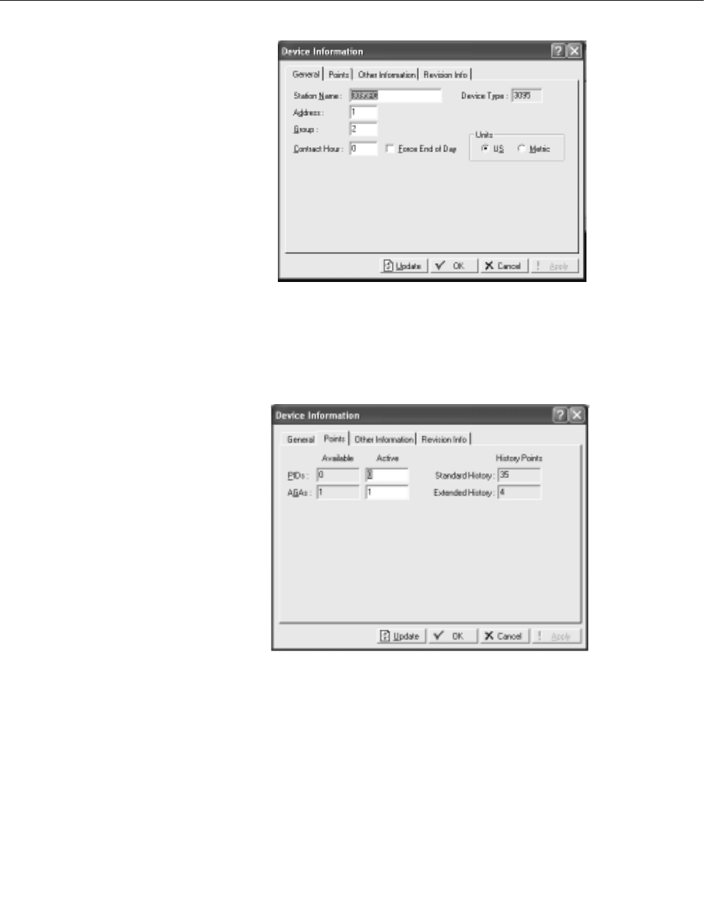
Reference Manual
00809-0100-4832, Rev AA
October 2004
3-11
Rosemount 3095FC
Figure 3-6. 3095FC
Differentiation / Information
General Screen
Points Tab
The Points screen allows the user to change the number of certain points that
will be active.
1. Select Device > Information > Points Tab
Figure 3-7. 3095FC
Differentiation / Information point
Tab Screen
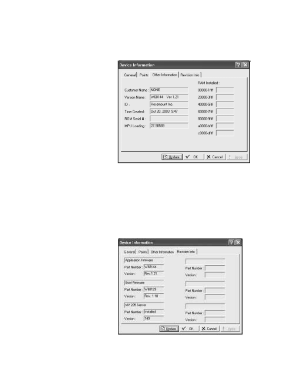
Reference Manual
00809-0100-4832, Rev AA
October 2004
Rosemount 3095FC
3-12
Other Information Tab
This tab displays information about the firmware (Version Name, Part
Number, ID, and Time Created), the boot firmware (Version Name, Part
Number, and Time Created), the processor (loading), amount of RAM
installed, and the ROM (customer name and serial number).
Figure 3-8. 3095FC
Differentiation / Information
Other Information Screen
Revision Info Tab
This screen displays information about the firmware or accessory software
installed in the 3095FC. The first field displays the name of an accessory if
one is installed. For example, this field may say I/O Expansion Board or
Turbine Interface. When the field displays Not Used, there are no additional
accessories installed. The part number and version control number may also
be displayed.
Figure 3-9. 3095FC
Differentiation / Information
Revision Info Screen

Reference Manual
00809-0100-4832, Rev AA
October 2004
3-13
Rosemount 3095FC
Security Configuration The 3095FC has two types of security.
• Rosemount User Interface Security - Enables access to the
Rosemount User Interface Software and what menu items the user can
access.
• 3095FC Security - Enables communication to the transmitter.
Rosemount User Interface Security - Menu and Log On
See Figure 3-10 on page 3-14.
Use Operator ID and Password controls who can log on to Rosemount User
Interface Software and the Access Level controls access to menus and
screens. Up to 21 different users are permitted.
1. Select Utilities > 3095FC User Interface Security.
2. Enter the 3 alphanumeric characters for each operator I.D. (login).
Each operator I.D. must be unique. The I.D.is case sensitive. The
default is LOI.
3. Assign the four numeric characters between 0000 and 9999 to define
the password for each operator I.D (login). Users can have the same
password. The default is 1000.
4. Assign an access level for each user
• Level 0: only allows access to several options in the File and
Display menus, plus all options in the Help menu.
• Level 1: allows access to the menu options of Level 0 and several
options in the View menu.
• Level 2: allows access the menu options of all lower level options,
Collect Data, EFM reports, and Meter menu.
• Level 3: allows access the menu options of all lower level options,
several options in the Device and File menu, and the
Configuration menu.
• Level 4: allows access the menu options of all lower level options
and several options in the Utilities menu.
• Level 5 (system administrator level: allows access to all menus
and options.
NOTE
To prevent unauthorized users from accessing the software, delete the default
factory-assigned login (username) LOI and the password 1000 after the
security parameters are established.
Ensure that someone has Level 5 Access prior to deleting LOI 1000.
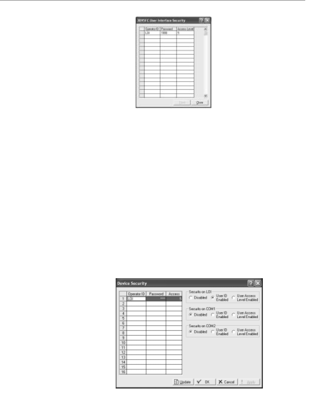
Reference Manual
00809-0100-4832, Rev AA
October 2004
Rosemount 3095FC
3-14
Figure 3-10. Security Access
Level Screen
3095FC Security
See Figure 3-11.
The 3095FC Security controls access to the device Comm Ports. When
enabled, login is required to use the communication ports. Each
communication port can be enabled or disabled separately.
The Access Level provides security for the 3095FC communication ports
depending on the value of the Comm Port Security parameter as defined by
the Comm Ports screen.
• Disabled - All login requested accepted. Access Level is ignored.
• Enabled - Login required (setup Operator ID and Password in
“Rosemount User Interface Security - Menu and Log On” on
page 3-13). Upon successful login, full read and write access is
allowed. Access Level is ignored.
• User Access Level Enabled - Login required (setup Operator ID and
Password in “Rosemount User Interface Security - Menu and Log On”
on page 3-13). Rejects a login request when the Access Level is
greater than the Access Level stored in the Utilities > 3095FC Security
Interface Security screen. This ensures the user is limited to the
Access Level configured in Rosemount User Interface.
Figure 3-11. Security Enable
Screen

Reference Manual
00809-0100-4832, Rev AA
October 2004
3-15
Rosemount 3095FC
LCD User List
Configuration
LCD User List Setup allows the user to assign up to 16 parameters to be
displayed on the LCD. Each parameter is displayed for three seconds before
continuing to the next.
1. Select Configure > LCD User List Setup.
2. Use the drop-down list box to select the desired LCD User List
Number (List No.) to configure.
3. Click the Point Definition TLP button to define the desired point
parameters to view on the LCD display. “Undefined” indicates that no
parameter has been specified.
4. Define up to 16 Data Point definitions to be displayed in the User List.
Enter the 10-character Description (Text) of the parameter.
I/O Configuration Configuring the 3095FC is a matter of establishing points and then configuring
various parameters. Each input and output has a unique Point Number to
identify the input or output. Each I/O point parameter must be individually
configured. The point number indicates the location of the point on the
termination board. It is automatically assigned and cannot be edited.
Each Point Number is given a Tag, which includes up to 10 characters to
identify the Point Number being defined in the I/O screen. Any alphanumeric
characters, including spaces, may be used.
NOTE
Units is a user-defined 10-character description for the engineering units
assigned to the I/O. For example: PSIG, MCF, degrees F, mA, or volts.
The I/O can be configured through either the Configure > I/O menu or the I/O
list on the Configuration Tree.
A1 - DP
A2 - SP
A3 - RTD
B1 - Aux AI
E1 - Logic Voltage
E2 - Bat Voltage
E3 - Spare
E4 - Spare
E5 - Brd Temp
Scanning Disabled versus Scanning Enabled
If scanning is set to disabled, the transmitter stops updating values for each
point number and values may be manually entered. Scanning Enabled allows
the transmitter to continuously update the parameters.
I/O Monitor
I/O Monitor displays all installed and active I/O points and flow calculation
information. The I/O Monitor screen shows the requested point information,
such as field I/O values or calculated flow values. These on-screen values are
automatically updated by Rosemount User Interface Software.

Reference Manual
00809-0100-4832, Rev AA
October 2004
Rosemount 3095FC
3-16
Analog Input (AI)
Configuration
Analog Inputs are analog signals generated by measurement devices, such
as pressure and temperature transmitters, including RTD probes.
The following tabs are available as part of the AI configuration:
• AI General tab
• AI Advanced tab
• AI Calibration tab (see “Analog Input (AI) Calibration” on page 4-3)
• AI Alarms tab
AI General Tab
The AI General Table sets the basic parameters for the Analog Input point.
Use the following steps to configure the AI General Tab.
See Figure 3-12
1. Select Device > I/O > AI Points > General Tab
2. Select the Analog Input.
3. Enter a 10-character Tag for identification of this Point Number.
4. Enter the Value and Units.
5. Select the Scanning option.
• When Scanning is set to Enabled, Value automatically displays
the last Analog Input scan in engineering units.
• When Scanning is set to Disabled (manual mode), the value is no
longer updated by the 3095FC. If Scanning is set to Disabled,
enter a value to override the input. If Alarming is Enabled, an
alarm generates when Scanning is set to Disabled.
6. Set the Alarming option. The Active Alarms field indicates any alarms
that are active for this point. For example, when Alarming is Enabled,
the limit alarms (such as Low Alarm and Rate Alarm) that are active
appear. Even if Alarming is Disabled, the Point Fail (hardware reports
a malfunction) alarm and Manual (Scanning Disabled) indicators can
still appear.
7. Enter the Scan Period as the amount of time between updates of the
filter value. All Analog Inputs are updated based on their individual
Scan Periods. The default value is 1 second. The minimum Scan
Period allowed is 50 msec.
8. Enter the Low Reading EU (engineering unit) corresponding to 0%
input. Enter the High Reading EU corresponding to 100% input.
For example: If a temperature transmitter is connected to the Analog
Input with a range of -40 °F to 212 °F, the Low Reading EU would be
set to -40 and the High Reading EU would be set to 212.
9. To complete point configuration click Apply.
10. Use Device > Flags > Flash Memory Save Configuration to save the
configuration to the Flash Memory in case a Cold Start must be
performed.
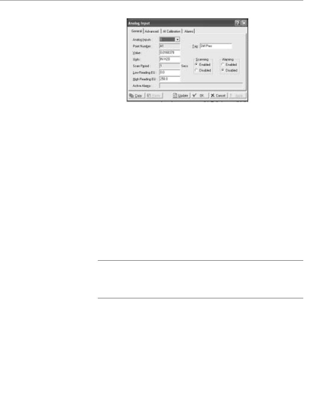
Reference Manual
00809-0100-4832, Rev AA
October 2004
3-17
Rosemount 3095FC
Figure 3-12. AI General Tab
Screen
AI Advanced Tab
The AI Advanced tab enables the user to configure features, such as filtering,
A/D conversions, and clipping for the selected Analog Input. Use the following
steps to configure the AI Advanced Tab.
See Figure 3-13 on page 3-18.
1. Select Device > I/O > AI Points > Advanced
2. Enter a Filter value, which is a weighted sample using a percentage
of the last value plus a percentage of the new value. The entered data
is the percentage of the last value used. The Filter is calculated every
Scan Period by the formula:
(Last Value × Entered %) + (New Value × (100 - Entered %)) = Filtered Value
3. Enter the Adjusted A/D 0%, which is the calibrated Analog-to-Digital
(A/D) reading that corresponds to 0%input. In the Calibrate function,
this value is altered to set the 0% input exactly at the Low Reading
EU value to eliminate transmitter and system errors.
4. Enter the Adjusted A/D 100%, which is the calibrated A/D reading
corresponding to 100% input. This value is used to convert the input
to engineering units. In the Calibrate function, this value is altered to
set the 100% input exactly at the High Reading EU value.
NOTE
Raw A/D Input displays the current reading directly from the analog-to-digital
converter. Actual Scan displays the actual amount of time in seconds that
passes between scans. This number should be the same as shown for the
Scan Period parameter if the system is not overloaded.
5. The Enable Average Raw Values calculates and averages the raw
readings during the Scan Period. Use the outcome as the Raw A/D
Input during calculations. For example: When Enabled, an Analog
Input point configured with a Scan Period of 1.0 seconds obtains a
new value from the A/D every 50 milliseconds. During the Scan
Period, 20 values are obtained from the A/D and summed together. At
EU Value calculation, the values summed are divided by the number
of samples taken during the scan period and are used as the Raw
A/D Input. Disable this function to acquire instantaneous values.
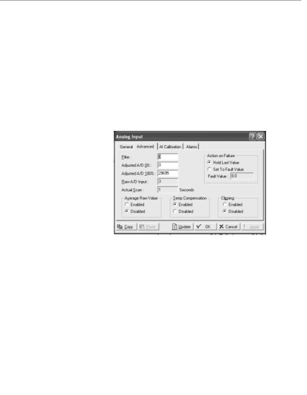
Reference Manual
00809-0100-4832, Rev AA
October 2004
Rosemount 3095FC
3-18
6. When Temp Compensation is Enabled, a temperature compensation
curve is applied to the Analog Input using the board temperature of
the 3095FC as a reference. Use this feature to improve the A/D
conversion accuracy at temperature extremes for modular Analog
Inputs only; built-in Analog Inputs already have temperature
compensation. When using this feature, be sure to perform a
calibration after it is Enabled.
7. When Clipping is Enabled, the 3095FC forces the Filtered EUs to stay
within the range defined by the cut off limits. Set the cut off limits by
using the LoLo Alarm and HiHi Alarm parameters (see “AI Alarms
Tab” on page 3-19).
8. To complete point configuration click Apply.
9. Use Device > Flags > Flash Memory Save Configuration to save the
configuration to the Flash Memory in case a Cold Start must be
performed.
Figure 3-13. AI Advanced Tab
Screen

Reference Manual
00809-0100-4832, Rev AA
October 2004
3-19
Rosemount 3095FC
AI Alarms Tab
See Figure 3-14 on page 3-20.
The AI Alarms tab sets the alarm parameters for the AI point.
1. Select Device > I/O > AI Points > Alarms
2. Set the values for the different alarms. There are six different alarms:
• Low Alarm: The limit value, in engineering units, to which the I/O
must fall to generate a Low Alarm.
• High Alarm: The limit value, in engineering units, to which the I/O
must rise to generate a High Alarm.
• LoLo Alarm: The limit value, in engineering units, to which the I/O
must fall to generate a LoLo Alarm. The value is set lower than the
Low Alarm.
• HiHi Alarm: The limit value, in engineering units, to which the I/O
must rise to generate a HiHi Alarm. The value is set higher than
the High Alarm.
• Rate Alarm: The value, in engineering units, that represents the
maximum amount of change permitted between updates. If the
change is equal to, or greater than this value, an alarm is
generated. To disable the Rate Alarm without disabling the other
alarms, the Rate Alarm value must be set greater than the Span of
the Analog Input or TDI.
• Alarm Deadband - The value, in engineering units, is an inactive
zone above the Low Alarm limits and below the High Alarm limits.
The purpose of the Alarm Deadband is to prevent the alarm from
being continuously set and cleared when the input value is
oscillating around the alarm limit. This prevents the Alarm Log
from being over-filled with data.
3. Select RBX Alarming
• Disabled if limit alarms are not necessary for this point. Even if
Alarming is Disabled, the Point Fail (hardware reports a
malfunction) alarm and Manual (Scanning Disabled) indicators
can still occur. To conserve Alarm Log space, only Enable
Alarming when necessary.
• If the host PC is configured to receive field-initiated calls, a
Report-by-Exception (RBX) option is available.
• On Alarm Set - When the point enters an alarm condition, the
3095FC generates a RBX message.
• On Alarm Clear - When the point leaves an alarm condition,
the 3095FC generates a RBX message.
• On Alarm Set and Clear - When point enters and leaves an
alarm condition, the 3095FC generates a RBX message.
4. To complete point configuration click Apply.
5. Use Device > Flags > Flash Memory Save Configuration to save the
configuration to the Flash Memory in case a Cold Start must be
performed.
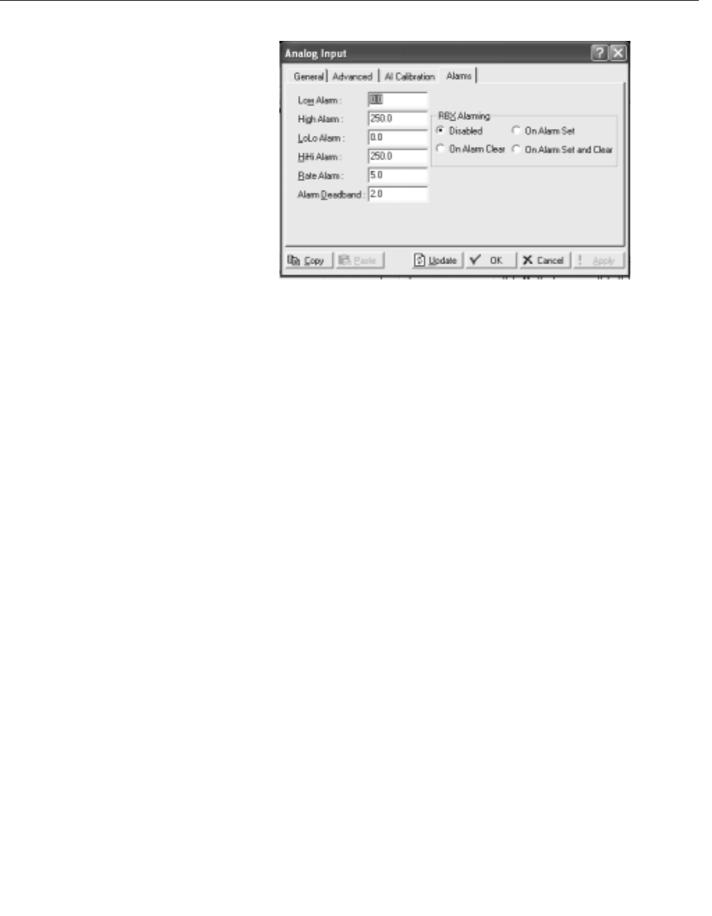
Reference Manual
00809-0100-4832, Rev AA
October 2004
Rosemount 3095FC
3-20
Figure 3-14. AI Alarms Tab
Screen
Soft Points Configuration Softpoints are data storage areas that can be used by any 3095FC
application. Softpoints consist of a Tag identifier, one integer value, and
twenty floating values. Softpoints consist of:
• tag identifier (10 character string)
• 20 floats (floating point values)
• 1 integer value (16 bit)
• 2 longs (32-bit)
• 10 shorts (16-bit)
• 10 bytes (8-bit). Select:
Use the following steps to configure the soft points
See Figure 3-15.
1. Select Configure > I/O > Soft Points.
2. Select the Softpoint to be configured or viewed.
3. Enter the Tag identification name (10-character).
4. The Integer Flag is a 16-bit unsigned integer value used as a flag to
denote the validity of the floating point data or as a counter.
5. Enter the Float number (1 - 20 parameters). These parameters
provide storage for IEEE floating point values.
6. To complete point configuration click Apply.
7. Use Device > Flags > Flash Memory Save Configuration to save the
configuration to the Flash Memory in case a Cold Start must be
performed.

Reference Manual
00809-0100-4832, Rev AA
October 2004
3-21
Rosemount 3095FC
Figure 3-15. Soft Point Screen
Opcode Opcode (operation code) is an instruction from a host system that informs a
slave device what actions to take. Table 3-1 contains a summary and brief
description of each Opcode. In some cases the number of data bytes returned
for an Opcode varies. For example, Opcode 0, a full update, always returns
certain input/output (I/O) information along with optionally specified data.
Table 3-1. Summary of
Opcodes Opcode Description
0 Send general update such as I/O update, gas flows, and control loop status.
6Send device configuration with 20 data bytes defining device configuration.
7 Send current time and date
8Set new time and date
10 Send data from configurable Opcode tables.
11 Set data in configuration Opcode tables
17 Set operator identification
18 Log event.
24 Store and forward
80 Reserved
103 Send system information such as on/off times, manual/alarm status, firmware
version, and current time and date.
105 Send history point definition, min/max data, and current values for specified history
point.
107 Send tag and current history period for specified history points.
120 Send pointer for alarm, even, and history logs
121 Send specified number of alarms starting at specified alarm pointer
122 Send specified number of events starting at specified event pointer
123 Read user template data
124 Read user Program Memory Allocation Information
126 Send last 60 minutes of data for specified history point.
128 Send archived daily and hourly data for the currently selected day and month
130 Send archived hourly and daily data for specified history point starting at specified
history pointer
131 Send specified number of event sequence numbers starting at specified pointer(1)
132 Clear specified number of event sequence number starting at specified pointer(1)
133 Send number of writable events(1)
148 Reads 240 bytes of data from a specified judgment: offset address
149 Reserved
160 Sends the entire structure for a specified Function Sequence Table (FST)

Reference Manual
00809-0100-4832, Rev AA
October 2004
Rosemount 3095FC
3-22
Certain Opcodes only send data and do not receive data from the device. For
example, Opcode 8 requests the device to set the time and date. The device
resets the time and date and sends back an acknowledgement in which the
Opcode is repeated, but no data bytes are transmitted back. All
acknowledgements are 8-byte messages that repeat the Opcode received,
but do not transmit any data bytes.
Opcode 255 is an error message indicator. This is also an 8-byte message
with no data bytes included. The Opcode is set to 255 to indicate the
message received by the device had Cyclical Redundancy Error, but
contained invalid parameters. For example, if a request was made for the
information on Analog input #9, but the device only has 8 Analog inputs (0–7),
the device would respond back with the 8-byte message with the opcode
equal to 255 (error).
Opcode Table Configuration
Use the Opcode Table to group data for more efficient communication.
Parameters from different point types can be assigned to the Opcode table
data points, substantially reducing the number of polls from a host PC.
See Figure 3-16 on page 3-23
1. Select Configure > Opcode Table.
2. Select the Table Number for the Opcode Screen.
3. If the configuration has changed, update the version number. The
version number field attaches a version number to an Opcode table
configuration. It is a floating point number.
NOTE
Each Opcode Data point has a TLP box for mapping TLP values into the
Opcode Table Data point. If a host PC asks for a specific Opcode Data point,
the 3095FC returns the value that is referred by the mapped TLP.
Once the parameters have been configured in the Opcode Table:
1. Opcodes 10 and 11 can be used to read and write data directly
without specifying the Point Type, Logical Number, or Parameter
Number (TLP).
2. Opcodes 180 and 181 can be used to read and write the parameter
data and do not include the parameter definition.
162 Sets a single parameter
165 Set or send current configurable historical data
166 Set specified contiguous block of parameters
167 Send specified contiguous block of parameters
180 Send specified parameters
181 Set specified parameters
190/195 Reserved
224 Send Spontaneous Report-by-Exception (SRBX or RBX) message to host
225 Acknowledge Spontaneous Report-by-Exception message from device
255 Error messages transmitted by device in response to a request with invalid
parameters or format.
(1) Industry Canada
Opcode Description
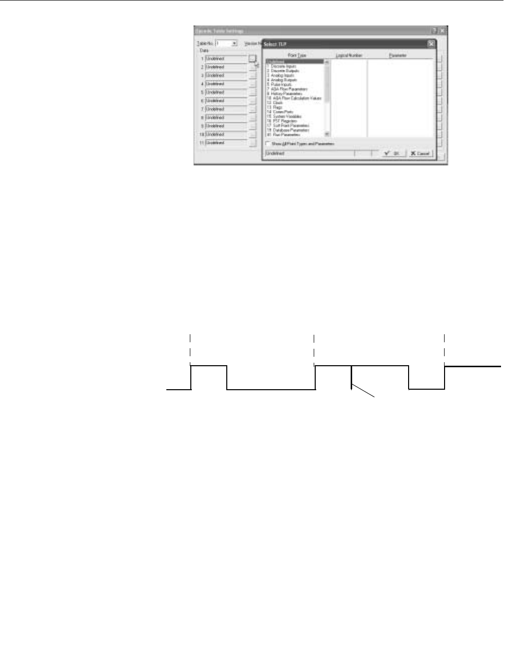
Reference Manual
00809-0100-4832, Rev AA
October 2004
3-23
Rosemount 3095FC
Figure 3-16. Opcode Table
Screen
Radio Power Control
Configuration
Radio Power Control conserves battery power to a radio or any other
communicating device. Radio power is controlled either by the DTR signal or
by a Discrete Output (DO). Because there are separate Radio Control points
for COM1 and COM2, radio power cycling for COM1 can be configured
differently from that for COM2, including independent timer values and
separate output controls using the Output Definitions options.
For each Radio Power Control point, the power cycling can be configured to
automatically change three times a day. During each of these three periods
(Zone 1, Zone 2, and Zone 3), the ON and OFF times can be setup to operate
at various intervals. Figure 3-17 is a graphical depiction of how the power
control operates within each time “zone.”
Figure 3-17. Radio Power
Control Timing
If communications occur during the ON time, the time is extended by the Hold
Time. The DO remains ON and receives interrupts remain enabled for the
duration of the Hold Time. When the Radio Power Control parameter is
Enabled, radio power cycling is activated. The Low Battery Shutoff parameter
allows power cycling to be automatically disabled whenever the input voltage
to the 3095FC falls below the specified threshold.
See Figure 3-18 on page 3-25.
1. Select Configure > Control > Radio Power Control.
2. Select the Radio Power Control point to be configured. Enter the Tag
(10-character) to identify this point.
During the ON time:
• The DO is switched to ON.
• Communication may occur.
During the OFF time:
• The DO is set to OFF.
• Communication does not occur.
Time = N Time = N
Off Time
On Time Hold TimeOn Time Off Time On Time
Host Communication Detected
Zone 1 Zone 2 Zone 3

Reference Manual
00809-0100-4832, Rev AA
October 2004
Rosemount 3095FC
3-24
3. Enter the The Radio Power Status, which indicates the current status
of the Power Control function of ON, OFF, or RBX. The Active Zone
indicates which zone is currently activated for determining the Start
Time, On Time, and Off Time. Some of the On Time is also used by
the radio during power-up initialization of the receiver, causing part of
the On Time to be unavailable for receiving requests.
4. Select Radio Power Control Enabled to activate the Radio Power
Control function.
5. Use the radio buttons to select Seconds and Minutes. In Seconds
mode, the time base for the timers is in 0.1 second increments,
primarily used with radios. In Minutes mode, the time base for the
timers is in one-minute increments, primarily used with cellular
telephones.
6. Enter the Zone parameters to indicate when Radio Power Control is
active/inactive.
• Start Time that the respective Zone begins, in hours and minutes
(HHMM). Time is expressed in local time, 24-hour clock. For
example: “1500” under Zone 2 means that the associated On
Time and Off Time are used beginning at 3:00 p.m.
• On Time during a power cycle when the output is in the ON state.
• Off Time during a power cycle that the output is in the OFF state.
7. Enter the Hold Time that the output remains ON after detection of
communications activity (in seconds, unless the Minutes mode has
been enabled). This value applies to all Zones. When
communications occur during the On Time, the On Time is extended
by the Hold Time.
8. Enter the Low Battery Deadband. The Low Battery Deadband value
is added to the Low Battery Shutoff to determine when the Radio
Power Control function is enabled and allows the DO to turn ON as
needed.
9. Enter a Low Battery Shutoff value that specifies the voltage at which
Power Control is automatically disabled. The voltage being sensed is
the System AI Battery Input voltage (0-1). The Low Battery Shutoff
parameter allows power cycling to be automatically disabled
whenever the input voltage to the 3095FC falls below the specified
threshold. The default value is 11 Volts.
10. Select the Power Timer, which counts down the amount of time (On
Time, Off Time, or Hold Time) that the Radio Control is currently
using. The value is the number of seconds remaining.
11. Select which DO point the signal will send along.
12. Enter the On Counter, which indicates the cumulative time that the
Power Control has been in the ON state. The Off Counter value
indicates the cumulative time that the Power Control has been in the
OFF state.
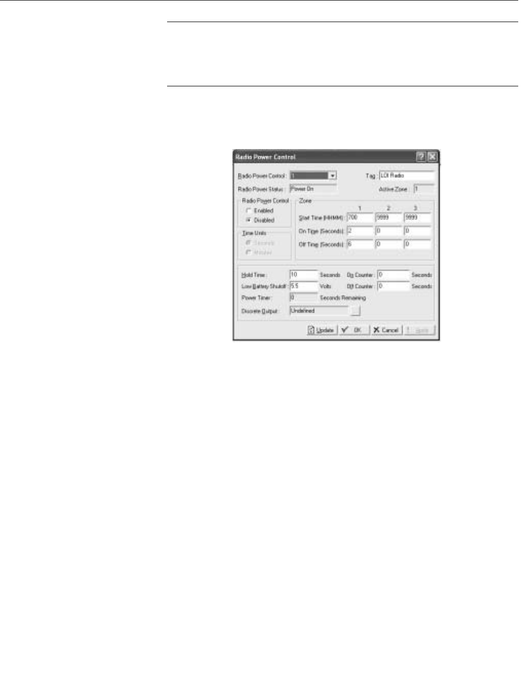
Reference Manual
00809-0100-4832, Rev AA
October 2004
3-25
Rosemount 3095FC
NOTE
If a Report By Exception (RBX) message needs to be sent to the host PC, the
radio power on DO will come on and allow the message to be sent. The hold
time should be long enough to allow the 3095FC to receive a response back
from the host.
13. Click Apply when configuration is complete. Save the configuration
using Device > Flags > Flash Configuration Memory Save.
Figure 3-18. Radio Power
Control Screen
Meter Run Configuration The Meter Setup screens allows configuring the AGA calculation point for the
connected 3095FC. The Meter Setup screens are used to configure the
computation of gas flow through a meter (Orifice AGA3)
Each meter run must be uniquely identified to ensure proper configuration and
allows the host to acquire the required data.
Each meter run Point Number is given a unique Meter ID of up to 10
characters to label the meter run for which this flow calculation is performed.
Use the Meter Description field to enter up to 30 characters to further identify
this meter run or provide information about the run.
The 3095FC uses AGA3 (1992) for flow calculation in orifice metering.
Additionally, the AGA8 compressibility method is used as well. The AGA8
method calculates the compressibility factor based on the physical chemistry
of the gasses at specified temperatures and pressures. The AGA8 method
provides extended capabilities for accurate computation of compressibility
factors beyond the temperature, pressure, and composition ranges of NX19.
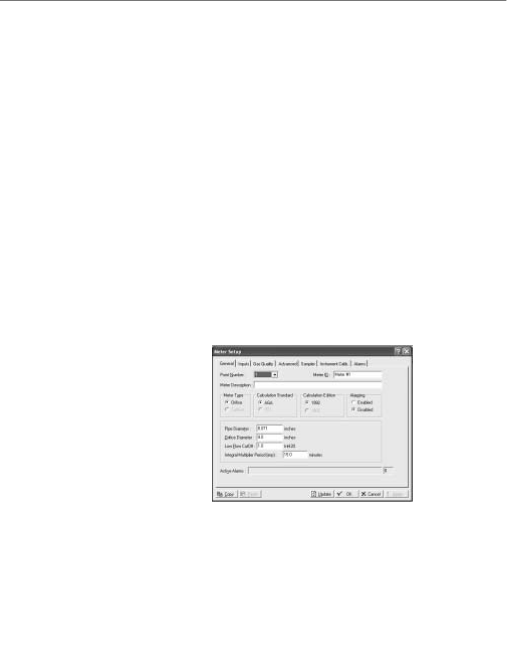
Reference Manual
00809-0100-4832, Rev AA
October 2004
Rosemount 3095FC
3-26
General Tab
The General tab sets the basic parameters for the meter.
See Figure 3-19 on page 3-26
1. Select Meter > Setup.
2. Select the Point number to be configured. Enter the meter tag. Enter
a unique Meter Description for the meter.
3. Select the Meter Type. Orifice is the default.
4. Select the Calculation Standard and Edition.
5. Select if Alarming is enabled or disabled.
6. Enter the inside Pipe Diameter (orifice) of the pipe, The U.S. units are
inches and the Metric units are millimeters.
7. Enter the Orifice Diameter (orifice) of the orifice. The U.S. units are
inches and the Metric units are millimeters.
8. Enter the Low Flow Cutoff (orifice) when the DP value of the metering
device is less than the Low Flow Cutoff value, the calculated flow is
set equal to zero. No Flow is recorded in the Alarm Log if Alarming is
Enabled. For the Orifice AGA3 calculation method, this value is in
inH2O (U.S.) or kPa (Metric).
9. Enter the Integral Multiplier Period (IMP) to indicate the frequency of
calculation in minutes of the Integral Multiplier Value (IMV) to be used
in the flow equation. The Integral Value (IV) portion of the flow
equation is calculated once per second. The value must be an integer
divider of 60, such as 1, 2, 3, 4, 5, 6, 10, 12, 15, 20, 30, or 60.
Figure 3-19. Meter Setup
General Tab Screen
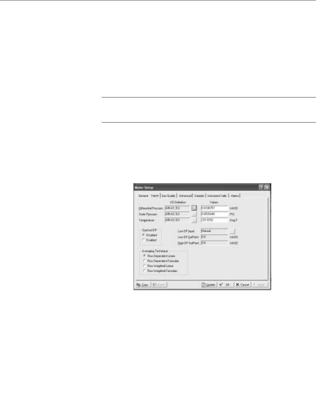
Reference Manual
00809-0100-4832, Rev AA
October 2004
3-27
Rosemount 3095FC
AGA Meter Inputs Tab
See Figure 3-20 on page 3-27.
The Inputs tab screen defines the field inputs, including DP and SP to be used
in the flow calculation.
To setup the meter inputs used in the flow calculation:
1. Select Meter > Setup >Input tab.
2. Click the Differential Pressure TLP button to assign the input that
senses the DP (high DP, if Stacked Dp is Enabled). The input units
are inH2O (U.S.) or kPa (Metric).
NOTE
If Manual appears, the Values field can be used to enter a value for the meter
input. Otherwise, the Values field indicates the current input value.
3. Click the Static Pressure TLP button to assign the input that senses
the SP. The input units are psig (U.S.) or kPa (Metric).
4. Click the Temperature TLP button to assign the input that senses the
temperature of the flowing gas. The input units are degrees
Fahrenheit (U.S.) or degrees Celsius (Metric).
Figure 3-20. Meter Setup Inputs
Tab Screen
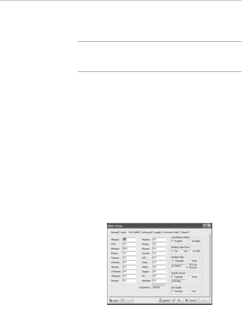
Reference Manual
00809-0100-4832, Rev AA
October 2004
Rosemount 3095FC
3-28
Gas Quality Tab
See Figure 3-21 on page 3-28
Gas Quality defines the mole percentage of twenty gas components, the
Heating Value Basis, the Heating Value, and the Specific Gravity.
NOTE
Entering Hexane+ (C6+) and the mole percent of hexane+ will automatically
distribute among hexane, heptane, octane, nonane, and decane as specified
by the heavy gas distribution parameters under the Advanced tab (“Advanced
Meter Setup Tab” on page 3-29.
1. Select Meter > Setup > Gas Quality tab.
2. Enter the mole percent of each Gas Component, or use the default
values of 96% methane, 3% ethane, and 1% nitrogen. The Total Mole
% should equal 100%. If changes are applied to the device when the
Total Mole % does not equal 100%, the composition will be adjusted
based on the Normalization Type selected.
3. Select Log Methane Adjust Enabled if the percentages are
automatically adjusted to total 100.
4. Select the Heating Value Basis. If Dry or Wet is selected, select
Calculate for the Heating Value parameter (the heating value is
always calculated on a dry basis). If As Delivered is selected, select
Enter for the Heating Value parameter and provide the value.
5. Select either Calculate or Enter for the capacity Heating Value of a
specified quantity of gas. If Calculate is chosen, the Heating Value is
calculated from the gas composition data. If Enter is chosen, the
value entered will be used in the heating value calculation. Use the
units button to toggle between volume or mass measurement U.S
units are BTU/Cf or BTU/Lb and the metric unit are MJ/m3 or MJ/Kg.
6. Select either Calculate or Enter for the Specific Gravity to specify the
ratio of the molar mass of the gas to the molar mass of air. If
Calculate is selected, the specific gravity is calculated from the gas
composition data at standard conditions of 14.73 PSIA and 60 °F. If
Enter is selected, the value entered for standard conditions is used.
Figure 3-21. Meter Setup Gas
Quality Tab Screen

Reference Manual
00809-0100-4832, Rev AA
October 2004
3-29
Rosemount 3095FC
Advanced Meter Setup Tab
See Figure 3-22 on page 3-30
The Meter Setup advanced tab contains a number of additional parameters
that affect the flow calculation.
1. Select Meter > Setup > Advanced tab.
2. Select the FPV Method of calculating the compressibility factor under
the 1992 AGA scheme. The three methods are:
• Detailed - Requires the natural gas composition in mole percent to
be entered.
• Gross I - Uses the density of the natural gas, its heating value, and
the quantity of non-hydrocarbon components as follows:
• Specific Gravity
• Real gas gross heating value per unit volume
• The mole % of CO2
• Gross II - Uses the density of the natural gas as well as the
quantity of non-hydrocarbon components as follows:
• Specific Gravity
• The mole % of CO2
•The mole % of N
2
NOTE
If either Gross Method is chosen, manually enter the Specific Gravity and
Heating Value in the Gas Quality screen. For Gross Method II, the heating
value is required only for calculating the gas energy flow.
3. Select the units (U.S. or metric)
4. Select either Calculate or Enter Atmospheric Pressure for the value of
the atmospheric pressure (absolute) at the metering location. If
Calculate is selected, the value is calculated from other parameters. If
Enter is selected, type a value greater than zero for the pressure. The
units of measurement are in psia (U.S.) or kPa (metric).
5. Enter the flow measurement Base Pressure specified in the gas
contract. The pressure units are in psia (U.S.) or kPa (metric).
6. Enter the flow measurement Base Temperature specified in the gas
contract. The temperature units are in degrees Fahrenheit (U.S.), or
degrees Celsius (metric).
7. Enter the Elevation or altitude of the metering location. The units are
in feet (U.S.) or meters (metric) is selected.
8. Enter the geographic Latitude of the metering location. The units are
in degrees (U.S.) and minutes separated by a decimal point (metric).
For example: 46.15.
9. Select the Pressure Tap used in the meter run.
• Select Gauge or Absolute as the way of measuring pressure at the
SP tap. The selection must be consistent with the type of pressure
measured by the sensor (absolute or gauge).
10. Select the Force Recalculation Set and click Apply to cause a full
recalculation of the flow without waiting for the next normal
recalculation.
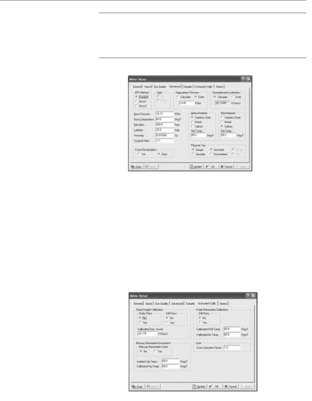
Reference Manual
00809-0100-4832, Rev AA
October 2004
Rosemount 3095FC
3-30
NOTE
Normal recalculation periods are established in Meter Set-up screen using
Integral Multiplier period or the Base Multiplier Period. Upon forcing a
recalculation, the accumulations are zeroed and the flow value is logged as a
new entry. The Force Recalculation parameter is automatically set to Clear
after the recalculation.
Figure 3-22. Meter Setup
Advanced Tab Screen
Instrument Calibration Tab
See Figure 3-23 on page 3-30.
The 3095FC Instrument Calibration options allow setting the calibration
parameters for the Analog Inputs of the flow calculation.
1. Select Meter > Setup > Instrument Calib tab.
2. Dead Weight Calibration - If a deadweight tester is used to calibrate
the DP or the SP, select the respective Yes option. Enter the
Calibrated Grav. Accel. value.
3. Enter the User Correction Factor value that is multiplied by the base
volume flow equation, allowing the user to make any desired
adjustment to the flow. When using the default value 1, no correction
is applied.
Figure 3-23. Meter Setup
Instrument Calibration Tab
Screen

Reference Manual
00809-0100-4832, Rev AA
October 2004
3-31
Rosemount 3095FC
Meter Setup Alarms Tab
See Figure 3-24 on page 3-32.
Meter Setup Alarms allows setting the alarm limits, configure RBX Alarming,
and view active alarms for the selected meter run. Alarms can be configured
for the individual meter runs and/or the stations, generating meter-specific
and /or station-wide alarm conditions.
For enable alarms, the alarms can be configured using the Alarms tab in the
Meter Set-up screen and are logged to the Alarm Log. To conserve log space,
alarms should be enabled only when necessary. For alarm disable, no alarm
is generated for a point, regardless of the Alarm configuration. Alarm
conditions display in the Active Alarm fields located in the Meter Configuration
screen.
NOTE
Even if alarms are not used, check and adjust the alarm value to prevent false
alarms.
Use the following steps to set the alarm values.
1. Go to Select Meter > Setup > General tab. Set the Alarming to Enable
(see “General Tab” on page 3-26).
2. Go to Select Meter > Setup > Alarms tab.
3. Enter the Low Alarm limit value, in engineering units, within the
calculated flow value resides to generate a Low Alarm. The default
value is 1000 MCF/day (U.S.) or km3/day (metric).
4. Enter the High Alarm limit value, in engineering units, within the
calculated flow value resides to generate a High Alarm. The input
units are 10000 MCF/day (U.S.) or km3/day (metric). The Active
Alarms field on the General tab indicates any alarm currently
activated. For example, Low indicates that the calculated flow is
below the Low Alarm limit.
5. Select the RBX Alarming option.
• On Alarm Set - When the point enters an alarm condition, the
3095FC generates a RBX message.
• On Alarm Clear - When the point leaves an alarm condition, the
3095FC generates a RBX message.
• On Alarm Set and Clear - When point enters and leaves an alarm
condition, the 3095FC generates a RBX message.
NOTE
RBX Alarming requires the communications port to be properly configured.
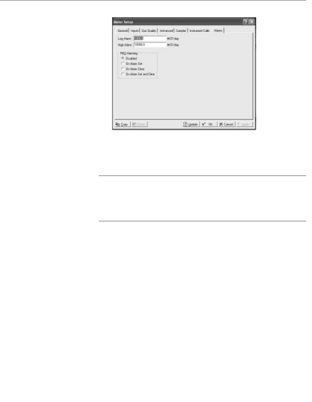
Reference Manual
00809-0100-4832, Rev AA
October 2004
Rosemount 3095FC
3-32
Figure 3-24. Meter Setup Alarms
Tab Screen
History Points
Configuration
The History option allows data stored in the current value database to be
copied and stored for up to a month in the historical database. The historical
database can be configured to log only the values that need to be logged. The
values are logged in the standard (minute-hourly-daily) time base.
NOTE
The time stamp used for standard logging reflects the time at the end of the
period, not at the beginning. For example: Data collected from 8:00 to 9:00 is
stamped 9:00.
The 3095FC also maintains a 10-minute historical database.
Four types of historical databases are maintained:
• Min/Max Database (see “Meter History")
• Minute Database (see “General History")
• Hourly Database (see “General History")
• Daily Database (see “General History")
Meter History
The Min/Max Database is for viewing only and cannot be saved to a disk file.
A total of fifteen history points may be accessed. For an AGA3 meter run, the
first eight (out of fifteen) history points are pre-configured for flow metering
history and cannot be changed. They are configured as follows:
1. Flowing Minutes Today (Accumulate archive type)
2. DP (Average)
3. Static or Line Pressure (Average)
4. Flowing Temperature (Average)
5. C´ or Integral Multiplier Value (IMV)
6. Pressure Extension or Integral Value (IV) (Average)
7. Instantaneous Flow (Accumulate)
8. Instantaneous Energy (Accumulate)

Reference Manual
00809-0100-4832, Rev AA
October 2004
3-33
Rosemount 3095FC
History Point 2, History Point 3, History Point 4, and History Point 6 are all
setup as an Average Archive Type that employs one of the following
techniques:
• Flow dependent time-weighted linear averaging (default)
• Flow dependent time-weighted formulaic averaging
• Flow-weighted linear averaging
• Flow-weighted formulaic averaging
Averaging Technique
The averaging technique is selected using Rosemount User Interface
Software. The user-configurable history points, 9-15, may be configured using
Rosemount User Interface Software. In the Meter > Setup > Inputs tab, select
the desired Averaging Technique. The selected Averaging Technique is
applied to the meter inputs.
History point archival includes:
• Archival of minute data from the last 60 minutes for 15 points.
• Archival of 60 days of 10-minute data for 4 points.
• Archival of 35 days of hourly data for 15 points.
• Archival of 35 days of daily data for 15 points.
• Archival of minimum / maximum historical data for today and yesterday.
Log Types
The following are logs that are available through the History Points data.
• Minute Historical Log: The 3095FC has a 60-minute historical log for
each history point. The Minute Historical Log stores the last 60 minutes
of data from the current minute. Each history point has Minute
Historical Log entries.
• 10-Minute Historical Log: The 3095FC has a 10-minute historical log
for up to four (4) history points that stores 60 days of 10-minute data.
The four (4) 10-Minute history points include DP, SP, flowing
temperature, and an auxiliary Analog Input.
• Hourly Historical Log: The 3095FC has a total of 35 days of hourly
historical logs available for every history point. The Hourly Historical
Log is also called the Periodic database. Normally, the Hourly Log is
recorded at the beginning of every hour. The time stamp for periodic
logging consists of the month, day, hour, and minute.
• Daily Historical Log: The 3095FC has a total of 35 daily historical logs
for every history point. The Daily Log is recorded at the configured
contract hour every day with a time stamp that is the same as the
Hourly Log. Each history point has daily historical log entries.
• Min / Max Historical Log: The Min / Max database displays the
minimum and the maximum values for the database points over a
24-hour period for today and yesterday. The Min / Max historical log
can be viewed, but not saved to disk.

Reference Manual
00809-0100-4832, Rev AA
October 2004
Rosemount 3095FC
3-34
• Alarm Log: The Alarm Log contains the change in the state of any
alarm signal that has been enabled for alarms. The system Alarm Log
has the capacity to maintain and store up to 240 alarms in a “circular”
log. The Alarm Log has information fields that include time and date
stamp, alarm clear or set indicator, and either the Tag name or a
14-byte detail string in ASCII format.
In addition to providing functionality for appending new alarms to the
log, the Alarm Log allows host packages to request the index of the
most recently logged alarm entry. Alarm Logs are not stored to the flash
ROM during the Save Configuration function in Rosemount User
Interface Software.
The Alarm Log operates in a circular fashion with new entries
overwriting the oldest entry when the buffer is full. The Alarm Log
provides an audit history trail of past alarms. The Alarm Log is stored
separately to prevent recurring alarms from overwriting configuration
audit data.
• Event Log: The Event Log contains changes to any parameter within
the 3095FC made through the protocol. This Event Log also contains
other 3095FC events, such as power cycles, cold starts, and disk
configuration downloads. The Event Log provides an audit history trail
of past operation and changes.
The system Event Log has the capacity to maintain and store up to 240
events in a circular log. The Event Log has information fields that
includes point type, parameter number, time and date stamp, point
number if applicable, the operator identification, and either the
previous, current parameter values, and either the Tag name or a
14-byte detail string in ASCII format.
In addition to providing functionality for appending new events to the
log, the Event Log allows host packages to request the index of the
most recently logged event entry.
Event Logs are not stored to Flash memory when Save Configuration is
issued in Rosemount User Interface Software. The Event Log operates
in a circular fashion with new entries overwriting the oldest entry when
the buffer is full. The Event Log provides an audit trail history of past
operation and changes. The Event Log is stored separately to prevent
recurring alarms from overwriting configuration audit data.

Reference Manual
00809-0100-4832, Rev AA
October 2004
3-35
Rosemount 3095FC
General History
The Configure > History option allows data to be stored in the historical
database. Hourly and daily values are stored for up to 35 days. The historical
database can be configured to log only the values that need to be logged.
NOTE
History points setup in the Meter > History screen override history points
setup in the Configure > History screen. When configuring history points
ensure that the point is not already defined in Meter History.
1. Select Configure > History Points.
2. Select the desired history point to be configured in Select History
Point. The parameter currently configured (if any) for this history point
appears in the Value to Archive field.
NOTE
The first eight history points are reserved for use as Meter History; begin
selecting history points with History Pt. #9.
3. Click the TLP Value to Archive label to specify a point type and
parameter to be archived.
4. Select the Point Type to archive. To prevent this history point from
logging values, select Undefined as the Point Type.
5. Select the Logical Number. For example, select Analog Input AIN A 2.
6. Select the specific Parameter to log.
7. Click OK.
8. Choose the Select Archive Type to specify the exact archive type of
the history point. The archive type affects how the logged value is
calculated.
• Undefined – Point not configured
• Disabled - Point not configured
• Average - Minute values are averaged to compute the hourly
value. The flow inputs (such as DP) allow the user to select among
four types of averaging for calculating flow quantities or for
providing values. Refer to the Select Average Type parameter.
• Accumulate - The flow, energy, or uncorrected flow values are
summed over a specified time period to compute the value based
on what is selected in the Select Accumulation Time Basis. The
accumulation technique is used to acquire accurate accumulated
counts from an input for a specified time period.
• Current Value - Current sampled value is used for the hourly
value.

Reference Manual
00809-0100-4832, Rev AA
October 2004
Rosemount 3095FC
3-36
• Totalize - The difference between the current value and last hour's
current value is used for point values polled or received as
accumulated values. The Totalization technique assumes that the
value being archived is zeroed out by something else at Contract
Hour and that no rollover of the value occurs. Totalization occurs
at the Minute Historical Log and is summed up for the Hourly and
Daily Historical Logs. A minute after Contract Hour, the current
value is archived. All other minutes are the difference between the
current value and the previous minute's archived value.
• Select Average Type -The Select Average Type parameter is set
to Average, this list appears at the bottom of the screen. Choose
one of the following options to determine how the average value is
calculated.
• Flow Dependant Linear - This is the default method for
calculating the average for the flow input. It is the simplest and
most commonly used method. This method discards samples
for periods when there is no measurable flow and performs a
straightforward (linear) average of the remaining samples to
compute the minute and hour values. The value specified in
the Low Flow Cutoff of the Meter setup determines the values.
When no flow occurs, all values are sampled.
• Flow Dependant Formulaic - Like the Flow-Dependent Linear
method, this method discards samples for periods when there
is no flow. However, in calculating the average, this method
typically takes the square root of each sample before
averaging the samples together and then squares the result.
This formulaic method produces a slightly lower value than the
linear method.
• Flow Weighted Linear - This method does not discard any
samples. Instead, it “weights” each sample by multiplying it by
a flow value (square root of the DP measured during the
sample period), and then performs a linear average by dividing
the sum of the flow-weighted sample by the sum of the flow
values. This results in minute and hourly values that are more
reflective of short periods of high flow.
• Flow Weighted Formulaic - This method combines the
flow-weighting action with the formulaic averaging technique,
both of which were described previously.
9. Select Accumulation Time Basis - When the Selected Archive Type is
Accumulate, this list appears at the bottom of the screen. Choose one
of the following options to determine how the accumulated values are
computed:
• Per Sec - Values summed to compute the second value.
• Per Min - Values summed to compute the minute value.
• Per Hour - Values summed to compute the hourly value.
• Per Day - Values summed to compute the daily value.

Reference Manual
00809-0100-4832, Rev AA
October 2004
3-37
Rosemount 3095FC
History, Alarm, Event,
and Audit Log Reports
History, Alarm, Event, and Audit Log can be viewed from the View menu.
History can viewed from an on-line Rosemount User Interface Software,
3095FC, or from a disk file. History and log files work in a circular fashion; the
newest data overrides the oldest data when the log is full.
Once a selected history log has been displayed, the following options are
available:
• Select New - Return to the Select History points screen and make a
new selection.
• Save - Save the history archives to a file.
• Print Preview - Show a preview of what will be sent to the printer and
allow printing of the history log.
• Close - Close the screen. View the History Logs from the View menu.
Once the alarms are displayed the following options are available:
• Save - Save the alarm log to a file.
• Print Preview - Show a preview of what will be sent to the printer and
allow printing of the alarm log.
• Close - Close the screen. View the Alarm Logs from the View menu.
Once the events are displayed the following options are available:
• Save - Save the event log to a file.
• Print Preview - Show a preview of what will be sent to the printer and
allow printing of the event log.
• Close - Close the screen. View the Event Logs from the View menu.
A report is generated based on the Search Criteria from the 3095FC.
1. Select View menu > History, Alarm, or Event > From 3095FC.
2. Select the History Points in the Search Criteria field (History only).
Select, Deselect All, and Select All allow the user to mass select or
deselect History Points. The Search Criteria selections change
depending on the Frequency.
3. Select the Frequency to be viewed (History only). The Minute, Hourly
(Hour), Daily (Day), or Minimum and Maximum (Min/Max) values can
be view.
4. Click Upload.
A report is generated based on the Search Criteria from a disk file.
1. Select View menu > History, Alarm, or Event Log > From File.
2. Select the file and click Open.
3. Perform one of the following:
• Select New - Return to the Select History points to be shown
screen and perform a new search.
• Invert - View the log in reverse order (default is newest to oldest).
This changes the time order of the Alarm, or Event Log.
• Save - Save the report to a file.
• Print Preview - Print the report.
• Close - Close the screen.

Reference Manual
00809-0100-4832, Rev AA
October 2004
Rosemount 3095FC
3-38
Collect Data Select 3095FC > Collect Data to save various 3095FC data to disk files.
Select the values to be saved for later generating into a report(s). This screen
may only be accessed when the user is on-line with the already configured
3095FC from which data will be gathered.
Use Save As and the Browse button to either accept the default File name or
enter a new File name. The files are saved in the default directory C:/Program
Files/Rosemount User Interface for Windows/Data unless another directory
was selected. When selecting EFM Report Data, the Collect Data function
saves all the values for EFM parameters. The files has the .efm extension.
The EFM Reports utility uses the flow data that was gathered using either the
“EFM Report Data” or the “All” option. The “All” function retrieves Rosemount
User Interface Software data including the EFM Report Data and stores it in
disk files identified with various extensions. The “EFM Report” function
retrieves just the detailed flow data needed for an EFM report and stores it in
disk files with an .AGA extension.
NOTE
EFM Reports can be created, using this data, by selecting View >EFM Report.
Configure History for
EFM Reporting
Electronic Flow Measurement (EFM) Reports
The Rosemount User Interface Software has the ability to create an EFM
report file that contains all the configuration, alarms, events, and history logs
associated with the stations and meter runs. This file becomes the custody
transfer audit trail. To collect the periodic and daily history logs required for the
EFM report file, a specific list of station and meter run parameters must be
configured for historical archiving.
For Orifice meters, the following history points must be configured for EMF
reports.
Table 3-2. Orifice Meter Run History Points
Description Archive Type Point Type Parameter
Flowing Minutes Totalize Orifice Meter Run Values Minutes Accumulated
DP Avg (Flow Dependent Linear)
Avg (Flow Dependent Formulaic)
Avg (Flow Weighted Linear)
Avg (Flow Weighted Formulaic)
Orifice Meter Run Configuration DP
SP Avg (Flow Dependent Linear)
Avg (Flow Dependent Formulaic)
Avg (Flow Weighted Linear)
Avg (Flow Weighted Formulaic)
Orifice Meter Run Configuration SP
Temperature Avg (Flow Dependent Linear)
Avg (Flow Dependent Formulaic)
Avg (Flow Weighted Linear)
Avg (Flow Weighted Formulaic)
Orifice Meter Run Configuration TMP
Pressure Extension Avg (Flow Dependent Linear)
Avg (Flow Dependent Formulaic)
Avg (Flow Weighted Linear)
Avg (Flow Weighted Formulaic)
Orifice Meter Run Configuration Pressure Extension
Multiplier Value Avg (Flow Dependent Linear)
Avg (Flow Dependent Formulaic)
Avg (Flow Weighted Linear)
Avg (Flow Weighted Formulaic)
Orifice Meter Run Configuration Multiplier Value
Volume Totalize Orifice Meter Run Configuration Flow Accumulated
Energy To t a l i z e Orifice Meter Run Configuration Energy Accumulated

Reference Manual
00809-0100-4832, Rev AA
October 2004
3-39
Rosemount 3095FC
Selecting View > EFM Reports opens the initial screen. The utility program is
used in conjunction with the AGA flow calculation capabilities of the 3095FC
to display or print previously collected flow data. EFM Reports generate
printed and on-screen reports of the historical flow data for a meter point.
Selecting EFM Reports causes the Rosemount User Interface Software to
suspend operation and load the EFM Reports Utility.
The flow data is contained in an EFM Report file, which includes the
operational characteristics of all the meter runs configured in the 3095FC. The
operational characteristics consist of Configuration Parameters, Hourly and
Daily History, Events, and Alarms associated with each measured meter run.
The Audit Log events are also included for Industry Canada custody transfer.
To create the EFM Report disk file, use Device > Collect Data and select
either the “EFM Report” or “All” option (“Configure History for EFM Reporting”
on page 3-38). Once the disk file is created, a report can be generated
anytime thereafter and connection/communication with the Rosemount User
Interface Software is no longer necessary. The EFM Reports utility formats
this report for a single meter run covering a specified period of time. The user
can choose to view the report or print the report.
NOTE
In order for the EFM Reports utility to work, the historical database in the
Rosemount User Interface Software or 3095FC must be configured so that
certain flow calculation values can be retrieved from memory.
1. Select View > EFM Reports.
2. Click the EFM Report File button to display a lists the names of all the
files that have the .AGA extension previously created by using the
Collect Data function (see “Configure History for EFM Reporting” on
page 3-38).
3. Select the desired file and click Open.
4. Use the Enter meter run drop-down list box to select the meter run for
which to create a report.
5. Enter the Start date and End date. Any alarms, events, hourly history,
and daily history records that occur between these dates will be
included in the report. Click Next.
6. Under the Available sections list select the Data files to be included in
the report. Use the arrows to scroll through the selections.
7. Click Next.
8. Select the Available Subsections to include in the report. Use the
arrows to scroll through the selections.
9. Click Next.
10. Select the Point Types and Fields to include in the report.
11. Click Finish. The EFM Report displays.

Reference Manual
00809-0100-4832, Rev AA
October 2004
Rosemount 3095FC
3-40
Modbus Configuration The 3095FC has the ability to communicate using Modbus protocol. This
makes it possible to integrate with Modbus devices into the same Host/Slave
system. The 3095FC can act as a Slave device.
The LOI, Comm 1, and Comm 2 ports all support Modbus communications.
The Modbus mapping on the Modbus Registers screen and Modbus History
Access Registers screen will affect Modbus communication on all of the
3095FC comm ports.
The 3095FC point types and parameters for Function Codes 1, 2, 3, 4, 5, 6,
15, and 16 are configured using the Rosemount User Interface Software.
Table 3-3 provides details of the Function Codes supported by the 3095FC.
Table 3-3. Modbus Function
Codes
General Tab
The General tab sets the basic communication parameters.
See Figure 3-25 on page 3-42
1. Select Configure > Modbus > Configuration > General tab
2. Select the Modbus Type. The Modbus protocol supports two modes
of transmission ASCII and RTU. All devices in the same
communications must be configured with the same mode of
transmission.
• American Standard Code for Information Interchange (ASCII) –
allows additional time intervals of up to one second to occur
between characters without causing an error. This allows the
messages to be read with the use of a dumb terminal. Each
character is divided into two 4-bit parts that are represented by
their hexadecimal equivalent. The ASCII mode uses twice as
many characters as the RTU mode. Each character sent is
composed of a Start bit, 8 or 7 Data bits, and one or two Stop bits
with Even, Odd, or No parity. ASCII mode uses Longitudinal
Redundancy Checking (LRC) error checking
Code Meaning Action
01 Read Logic Coil Status Obtain current status (ON/OFF) of a group of
logic coils (outputs)
02 Read Discrete Input Status Obtain current status (ON/OFF) of a groups of
Discrete Inputs
03 Read Output Registers (Holding) Obtain current binary value in one or more
holding requests
04 Read Input Registers Obtain current binary value in one or more binary
registers
05 Force Single Logic Coil Force logic coil to a state of ON or OFF.
Acknowledge Alarm or Event request
06 Preset Single Holding Register Place a specific binary value into a holding
register
15 Force Multiple Logic Coils Force a series of consecutive logic output coils
to defined ON or OFF states.
16 Preset Multiple Holding Registers Place specific binary values into a series of
consecutive holding registers.

Reference Manual
00809-0100-4832, Rev AA
October 2004
3-41
Rosemount 3095FC
• Remote Terminal Unit (RTU)– Allows for greater character density
and better data throughput than ASCII for the same baud rate.
Each message is transmitted in a continuous stream. Data is sent
in 8-bit binary characters. In the ASCII mode, each RTU character
is divided into two 4-bit parts that are represented by their
hexadecimal equivalent. RTU mode uses Cyclic Redundancy
Check (CRC) error checking. By default, RTU is enabled.
In either mode, ASCII or RTU, a Modbus message is placed by the
transmitting device into a frame that has a known beginning and
ending point.
Table 3-4. Message Framing
3. Select Log Modbus Events Enabled to log all Modbus parameter
changes to the Event Log or select Disabled to allow Modbus
parameter changes to occur without being logged. By default, Log
Modbus Events is Enabled.
4. Select the Byte Order of data bytes in a transmission or request can
be reversed by the selection made in these check boxes. This only
affects the Data field of a Modbus message, has no effect on the data
for Function Codes 01, 02, and 05, and only applies to floating points.
• Least Significant Byte First - Selecting this check box places the
least significant byte first. This is the default value.
• Most Significant Byte First - Selecting this check box places the
most significant byte first.
5. Select EFM Modbus Enable to use an implementation of Modbus
protocol with EFM extensions. This causes the Hourly (Periodic) and
Daily indices to be returned as floating point values instead of the
standard integer and character values. In addition, the history index is
adjusted to accommodate a one-based index (1 to 840), and the date
stamp (MMDDYY) is returned before the time stamp (HHMM), which
does not include seconds.
6. The “status” field displays the status codes returned from the modem.
ASCII Message Framing
Begin of
Frame Address Function Data
LRC Error
Check End
: 2 characters 2 characters N characters 2 Characters CRLF
RTU Message Framing
Begin of
Frame Address Function Data
CRC Error
Check End
T1-T2-T3-T4 1 Byte 1 Byte N * 1 Byte 2 Bytes T1-T2-T3-T4
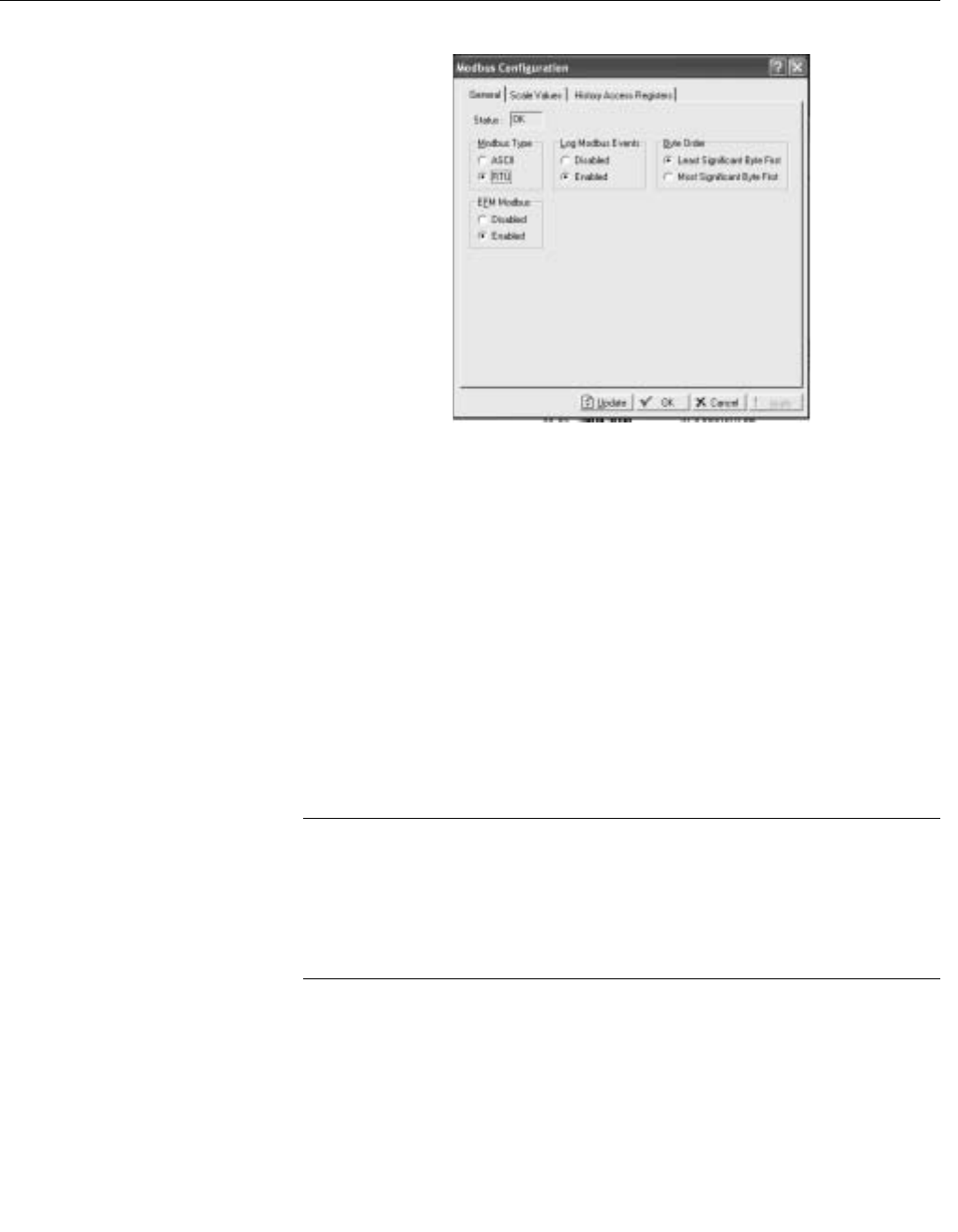
Reference Manual
00809-0100-4832, Rev AA
October 2004
Rosemount 3095FC
3-42
Figure 3-25. Configure Modbus
General Tab Screen
Scale Values Tab
The Scale Value tab allows the user to enter low and high floating point and
integer values for converting between integer and floating point numbers.
See Figure 3-26 on page 3-43
1. Select Configure > Modbus > Configuration > Scale Values tab.
2. Enter the Integer Scale values. In the 3095FC, the endpoints of the
Analog Inputs and the Analog Outputs are used to scale or calibrate
the range of the input or output signal. Because each I/O point can
have different scaling, the raw values from the Analog I/O points are
normalized to the values defined by the Integer Scale Low Value and
Integer Scale High Value fields.
3. Enter the Low Value that contains the 0% value for all analog data
(Type 3, Parameter 17 and Type 4, Parameter 9) registers. Enter the
High Value that contains the 100% value for all analog data (Type 3,
Parameter 17 and Type 4, Parameter 9) registers.
NOTE
The High and Low Value fields are signed integers, so they can range from
zero to 32767. These data fields can also be used to scale the Analog I/O to
integer values with an implied decimal point. For example: All Analog I/O Raw
values can be transmitted with 0 to 1000 values (0 to 100.0, decimal point
implied) by setting the values in this field to 0 for the Integer Scale Low Value
and 1000 for the Integer Scale High Value.
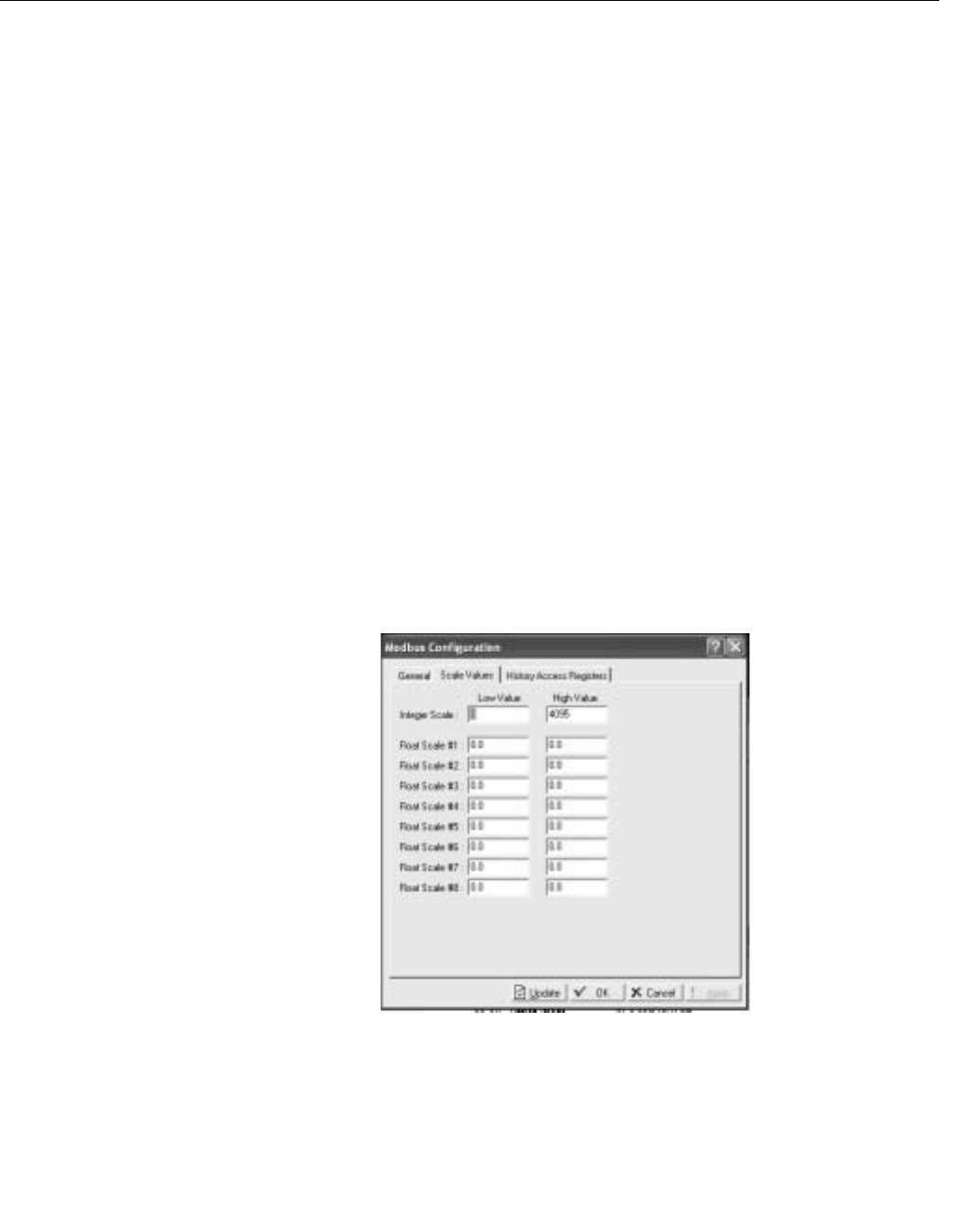
Reference Manual
00809-0100-4832, Rev AA
October 2004
3-43
Rosemount 3095FC
4. Enter the Float Scale # in the Low Value Float Scale and High Value
Float Scale fields used when the Host is not able to process floating
point numbers.
In Host systems that do not accept floating point numbers, eight sets
of floating point ranges for values can be specified. This allows
floating point values, such as PID Setpoints, to be read and set by the
Host as integer values. The 3095FC floating point values are
converted to integers by configuring a register or range of registers
with the Conversion field set in the Modbus Registers Definition
configuration.
The equations used to convert floating point values to integer values
to enable the reading of floating point values are:
• Float Range = High Value Float Scale - Low Value Float Scale
• Integer Range = High Value Integer Scale - Low Value Integer Scale
• Adjusted Reading = Float Reading - Low Value Float Scale
• Integer = (Integer Range × Adjusted Reading)/(Float Range) + Low Value
Integer Scale
The equations used to convert integers to floating point values are:
• Float Range = High Value Float Scale - Low Value Float Scale
• Integer Range = High Value Integer Scale - Low Value Integer Scale
• Adjusted Integer = Integer Sent - Low Value Integer Scale
• Float Value = (Adjusted Integer × Float Range)/(Integer Range) + Low
Value Float Scale
Figure 3-26. Configure Modbus
Scaled Values Tab Screen

Reference Manual
00809-0100-4832, Rev AA
October 2004
Rosemount 3095FC
3-44
Modbus - History Collection
The Modbus protocol sends the Hourly (periodic) and Daily History. Refer to
“History Access Registers Tab” on page 3-44. Each record contains a time
and date stamp and all of the history archives for which the Register Number
is configured. The Modbus Function Code 03 and the History Archive
Register are used to collect the archived data. Two Modbus registers indicate
the current Hourly and Daily history index as selected in the Archive Type
field. These can be configured in the Hourly History Index Register and the
Daily History Index Register. These indexes identify the current history
archive at which data was last logged.
To collect the Hourly and Daily history a standard Modbus Function Code 03
is used. The Register Number field is used to address the individual History
Archive Register. The Daily Index, Hourly Index, and Event/Alarm data fields
are used to address a history index number. The response message contains
two floating point values for the time and date stamp of the history archive
(time stamp = HHMMSS and date stamp = MMDDYY) and floating point
values for each of the defined history points for that History Archive Register.
The date stamp for history uses the current year and does not figure the
number of years since 1980.
NOTE
When in Modbus with EFM extensions mode, the time stamp is in the HHMM
format. In addition, the date time stamp is returned before the time stamp.
History Access Registers Tab
See Figure 3-27 on page 3-45
The History Archive Register is a single register that can contain one or more
history points for retrieval of the Event Log, Alarm Log, and Historical
Archives. Historical data is contained in Point Type 55 up to 35 days of hourly
data for each of its history points can be stored. The points mapped on the
history tab are configured on the Configure > History Points screen.
1. Enter Configure > Modbus > Configuration > History Access
Registers tab.
2. Enter the modbus Register Number used to acquire the Daily Index
values.
3. Enter the Modbus Register Number used to acquire the Hourly Index
values.
4. Enter the Modbus Register Number used to acquire the Events/Alarm
logs.
5. Enter the Modbus Register Number used to acquire the group of
history points defined in the Starting History Point and Ending History
Point fields without having to define each history point separately.
6. Enter the Starting History Point to acquire a group of history points
without having to define each history point separately, enter values in
the Starting History Point and Ending History Point fields. The Starting
History Point value is the first history point to be retrieved.
7. Enter the Ending History Point to acquire a group of history points
without having to define each history point separately, enter values in
the Starting History Point and Ending History Point fields. Then
Ending History Point is the last history point to be retrieved.
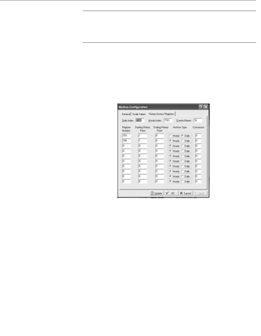
Reference Manual
00809-0100-4832, Rev AA
October 2004
3-45
Rosemount 3095FC
NOTE
The Starting History Point and Ending History Point values must be different
with the Starting History Point value being the smaller of the two. The group of
history points is specified by the Modbus register value set in the Register
Number field.
8. Enter the Archive Type to archive either Hourly or Daily values.
9. Enter the Conversion field to specify the type of conversion required,
if any, on the data before it is sent to the Host or before it is written to
the 3095FC. The conversions are used to allow integer values
instead of floating point values to be transmitted and received.
Table 3-5 summarizes the applicable function calls and their
associated register and data fields.
Figure 3-27. Modbus History
Access Registers Screen
Modbus - Events / Alarms Functionality
The record formats for the Event log and Alarm log are the same size and
have similar contents. The first word in a record is a bit map in which bit 9
indicates if the log record is an Event (1) or an Alarm (0). The meanings of the
other bits are specific to either the event or the alarm log records. The Event
and Alarm log record consists of the bytes shown in Table 3-6. A breakdown
of the bit map in the first byte is given in the table immediately after the record
table.

Reference Manual
00809-0100-4832, Rev AA
October 2004
Rosemount 3095FC
3-46
Table 3-5. History, Event, and
Alarm Functionality
The 3095FC supports the Modbus with EFM extensions method for retrieving
alarms, events, and history. When a Function code 3 request referencing
defined Events/Alarms Register (usually 32) is received, it begins to collect
records from first the Event Log and then the Alarm Log, starting where the
last poll left off. The 3095FC will collect records until either there are not any
more new events/alarms or the maximum of twelve records have been
collected. The 3095FC sends the information back to the host, which in return
replies with Function Code 5, referencing the same Events/Alarms Register,
indicating that the points have been received and that the host is ready for the
next twelve records.
When the 3095FC receives a Function Code 3 request referencing one of the
user-defined Periodic History Registers or Daily History Registers, the
number of registers field is interrupted as an index into the specific history log.
The reply message contains the date and time stamp and historical values
configured for the specified for that index.
Reading Events / Alarms Register
The Modbus request to read the Event/Alarm log (see Table 3-6) uses the
standard read Function Code 03 and the Event/Alarm Register (parameter
#0) in the Modbus Special Function Table (point type 39). In this request,
the number of registers is included to maintain format compatibility but is
ignored by the receiving 3095FC unit. For the date stamp in the events
and alarms returned, the year (YY) is really the number of years since
1980 (for example, the current year is 1997, so the year (YY) for the date
stamp would be 17).
Acknowledging Events / Alarms
The Modbus request to acknowledge the event/alarm log uses Function
Code 05 and the Event/Alarm Register (parameter #0) in the Modbus
Special Function Table (point type 39). In this request, the number of
registers is always one (1).
Function
Code Register Field Data Field Description
3 7160 – Daily Index Ignored Response contains current daily index
37161 – Hourly Index Ignored Response contains current hourly index
3 32 – Event/Alarm Register Ignored Response contains Events and Alarm records. Maximum number of bytes
returned is 240 (12 records of 20 bytes each). Events are returned before
Alarms are returned. The format is displayed in Table 3-6.
532 – Event/Alarm Register Ignored After Events and Alarms have been returned, there must e an
acknowledgement made so that the same Events and Alarms are not returned
on the next request.
3 703 – 7160 – Daily History History Archive
Register (0 to 34)
Response contains two floating point values for the time and date stamp of the
history archive (time stamp = HHMMSS and date stamp = MMDDYY) and
floating point values for each of the defined history point for that History Archive
Register.
3704 – Hourly Index History Archive
Register (0 to
8.39)
Response contains two floating point values for the time and date stamp of the
history archive (time stamp = HHMMSS and date stamp = MMDDYY) and
floating point values for each of the defined history point for that History Archive
Register.

Reference Manual
00809-0100-4832, Rev AA
October 2004
3-47
Rosemount 3095FC
Table 3-6. Modbus Events and
Alarms Log Content
Modbus - Detailed Point / Parameter Information
The Modbus Special Function Table (point type 39) returns the Event Log,
Alarm Log, and the Historical Archives. The Event/Alarm Register (parameter
#0), Hourly (periodic) History Index Register (parameter #1), and the Daily
History Index Register (parameter #2) can be configured to the desired
Register Number. The History Archive Register is a single register, which can
contain one or more history points for retrieval. The Starting History Point field
contains the Starting History Point for the History Archive Register, while the
Ending History Point is the last history point to be included in the History
Archive Register. All history points in between the Starting History Point and
the Ending History Point are included in the History Archive Register. The
Type of History Archive can only be one of two choices: Hourly or Daily. The
Conversion Code can be used to convert the history values. However, the
Conversion Code does not affect the time and date stamp.
Configure Modbus
Registers
The Modbus register configuration tables are used to associate Modbus
register numbers with 3095FC point data. When a Modbus request is
received, the Modbus user program searches the function table for the
Modbus function requested, starting with the first table entry down to the last.
If a register number match is found, it builds a response based on the point
type and parameter configured in the table. If no register number match is
located, an error message is returned. The user program locates a register as
long as it matches the Starting Register number, the Ending Register number,
or any number in between for that particular entry in the table.
Byte Content of Event Log Record Contents of Alarm Log Record
1 – 2 Operator change bit map (16-bit) Alarm change bit map (16-bit integer)
3 – 4 Modbus register number of variable (16-bit integer) Modbus register number of variable (16-bit integer)
5 –8 Time Stamp (HHMMSS; 32-bit floating point) Time Stamp (HHMMSS; 32-bit floating point)
9 – 12 Date Stamp (HHMMSS; 32-bit floating point) Date Stamp (HHMMSS; 32-bit floating point)
13 – 16 Previous value of variable (32-bit floating point) Current (alarmed) value of variable (32-bit floating point)
17 – 20 Current (new) value of variable ((32-bit floating point Unused at the current time (zero filled when transmitted to the master)
Bit Operator Change Bit Map Alarm Changed Bit Map
0 Fixed value - change to an EU value on an I/O point in Manual mode Not used
1Zero scale - change to the 0% Adjusted on an AI Not used
2 Full scale - change to the 100% Adjusted on an AI Not used
3Operator entry work value - change to any parameter other than those described Not used
5 Fixed / variable flag - change to manual mode for an I/O point Manual alarm
6Table entry change - change to Modbus Function Tables Status change alarm
7 System command change - events logged by system (power up) No flow alarm
8Not used Point fail alarm
9 Operator change event identifier bit Operator change even identifier bit
10 LoLo Limit - change to LoLo alarm parameter LoLo Alarm
11 Low Limit - change to Low alarm parameter Low Alarm
12 HiHi Limit - change to HiHi alarm parameter HiHi Alarm
13 High Limit - change to High alarm parameter High Alarm
14 Rate of change limit - change to Rate Alarm parameter Rate Alarm
15 Not used Set/clear alarm (1=set, 0=clear)

Reference Manual
00809-0100-4832, Rev AA
October 2004
Rosemount 3095FC
3-48
Register numbers should be unique for a given communication port.
Registers may be duplicated as long as they are assigned to separate port or
located in a separate Modbus configuration table. If a register number is
duplicated within the same Modbus function table, the first occurrence is
used. In addition, it is best to number the table from the smallest register
number to the largest register number, especially when using two table entries
to configure a continuous group of registers. Up to fifteen different lines can
be configured for Modbus Functions 4 and 16. Up to thirty different lines can
be configured for Modbus Function 3, split into tables 3A and 3B. By making
the registers continuous, meaning the Starting Register address of a new line
is one greater than the Ending Register address of the previous line, a
continuous data table can be created up for Modbus Function 3, 4, or 16 up to
the limit of 240 bytes. This type of data table allows access to all its data with
one request.
Up to fifteen different lines can also be configured for Modbus Function Codes
1, 2, 5, 6, and 15. For Function Codes 1, 2, 5, and 15, the parameter specified
should be a single-byte parameter type, preferably a status parameter (only
bit 0 is used), because this function packs the data into a binary format for
transmission. Each address span must be unique within the function for
proper operation. If not, the first valid address is used.
Modbus Register tables allow the user to map Modbus Registers to 3095FC
Point Type, Logical, and Parameter (TLP) numbers. One line in the Modbus
Register table can be used to map more than one register-TLP pair by using
either Point Indexing or Parameter Indexing.
Point Indexing means that the Start Register is mapped to the selected TLP.
Subsequent registers, through the End Register, are mapped to the same
point type and parameter and increment as the point logical number.
Parameter Indexing means that the Start Register is mapped to the selected
TLP. Subsequent registered, through the End Register, are mapped to the
same point type and point logical number, and increment the parameter
number.
Once a register is mapped, it can be referenced by any Modbus request,
providing the data type of the TLP is appropriate for the Function Code. If the
native 3095FC data type does not me the requirements of the Modbus host
device, conversion codes are available to convert data to the required data
type. The user can select to have the mapping apply to all 3095FC
communication ports or on a selected port only.
Use the following steps to Configure the Modbus Registers.
See Figure 3-28 on page 3-51.
1. Select Configure > Modbus > Modbus Registers. (See Table 3-7 on
page 3-49).
2. Select the Function Index to which the maps are to be registered.
There are 9 function indexes available, each corresponding to a
Function Code displayed in the Function name field. Refer to Table
3-2 on page 3-38 for a detailed description of supported Modbus
Function Codes.
3. Enter a Function Name up to 20 characters to distinguish between
the different Modbus Register tables.

Reference Manual
00809-0100-4832, Rev AA
October 2004
3-49
Rosemount 3095FC
Table 3-7. Modbus Registers
4. Enter a Starting Register to represent the first data register in the
address span. Any number from 0 to 65535 is valid. Register
numbers can be duplicated as long as they are in separate Modbus
Function configuration tables. The tables should be numbered from
smallest to largest. For example, the Host device requests the
Starting Register 500 through Ending Register 700. The Starting
Register is 400 and the Ending Register is 700. All register numbers
requested by the Host (500 through 700) are valid and would be
responded because the requested register numbers fall between the
Start and Ending Register numbers (400 through 700).
5. Specify that the Ending Register address is a number representing
the last location of a point's data. The value for this number is
computed by: Ending Register address = (Starting Register address +
Number of Functions) - 1
6. The Device Parameter field denotes the type of data associated with
an address (Starting through Ending Register). When the Host
requests a valid range of register numbers, the Function Code tells
the Slave what to do and between which registers (Starting Register
through Ending Register). The Rosemount User Interface Software
Parameter defines what data is collected or which parameter is set.
Function
Code Row
Starting
Register
Ending
Register Device Parameter (s) Indexing Conversion
1 1 1070 1070 N/A Point 0
2 1 0 0 N/A Point 0
3 1 7052 7059 Filtered EUs (Analog Inputs 1-8) Point 0
2 7100 7102 DP, P, Temp Param 0
3 7103 7107 Meter Flow Values - Starting with “Flow Rate/Day,” Ending with “hwPf” Param 0
4 7108 7127 Meter Flow Values - Starting with “Flow Today,” Ending with
“Uncorrected Accumulated”
Param 0
5 7262 7288 Meter Config Parameters - Starting with “Atmospheric Pressure,”
Ending with “Carbon Monoxide”
Param 0
4 1 0 0 N/A Point 0
5 1 1070 1070 N/A Point 0
6 1 7052 7059 Filtered EUs (Analog Inputs 1-8) Point 0
27100 7102 DP, P, Temp Param 0
37103 7107 Meter Flow Values - Starting with “Flow Rate/Day,” Ending with “hwPf” Param 0
47108 7127 Meter Flow Values - Starting with “Flow Today,” Ending with
“Uncorrected Accumulated”
Param 0
57262 7288 Meter Config Parameters - Starting with “Atmospheric Pressure,”
Ending with “Carbon Monoxide”
Param 0
15 0 0 0 N/A Point 0
16 18000 8053 Meter Config Parameters - Starting with “Point Tag ID,” Ending with
“Low Flow Cutoff”
Param 0
28054 8063 All Meter Calibration Parameters - Starting with “Calibration Options) Param 0

Reference Manual
00809-0100-4832, Rev AA
October 2004
Rosemount 3095FC
3-50
For example: When using Point Indexing the configuration of:
Specifies four Registers (100, 101, 102, and 104) that are mapped to
a group of Analog Input (AIN) values in engineering units (EU)
starting at the Analog Input in the forth module location, first position
(4-1).
• Register 100 - EU of AIN point in location 4-1
• Register 101 - EU of AIN point in location 4-2
• Register 102 - EU of AIN point in location 4-3
• Register 103 - EU of AIN point in location 4-4
For example: When using Parameter Indexing the configuration of:
Specifies three Registers (7100, 7101, and 7102) that are mapped to
a group of AGA parameters starting at CUR DP.
• Register 7100 - CUR DP (hw - differential pressure)
• Register 7101 - CUR SP (Pf - static pressure)
• Register 7102 - CUR TP (Tf - temperature)
7. Select the type of Indexing to define the block of Register values for
the Point Types or the Parameters without having to define each
separately.
• Select Point to define the Register values as Point Types. If
multiple Registers are used (Starting and Ending Register values
are different), each successive Register increments to the next
logical point number of the same Point Type.
• Select Param to define the Register values as Parameters. If
multiple Registers are used (Starting and Ending Register values
are different), each successive Register increments to the next
logical Parameter of the Point Types to be set or acquire data. Be
aware of the different data types (Character, Integer, Long, Float)
and the size of the data types. Use the TLP button to select
parameters.
8. Specify the type of Conversion required, if any, on the data before it is
sent to the host or written to the 3095FC. The conversions are used
to allow integer values to be transmitted and received instead of
floating point values. Table 3-8 lists the Convert Codes used with the
Modbus Protocol Emulation program. Conversion codes affect
Function Codes 3, 4, 6, 8, and 16.
Starting
Register
Ending
Register
Device
Parameter(s) Indexing Conversion
100 103 AIN, 4-1, EU Point 0
Starting
Register
Ending
Register
Device
Parameter(s) Indexing Conversion
7100 7102 AGANEW1,
CUR DP
Parameter 0
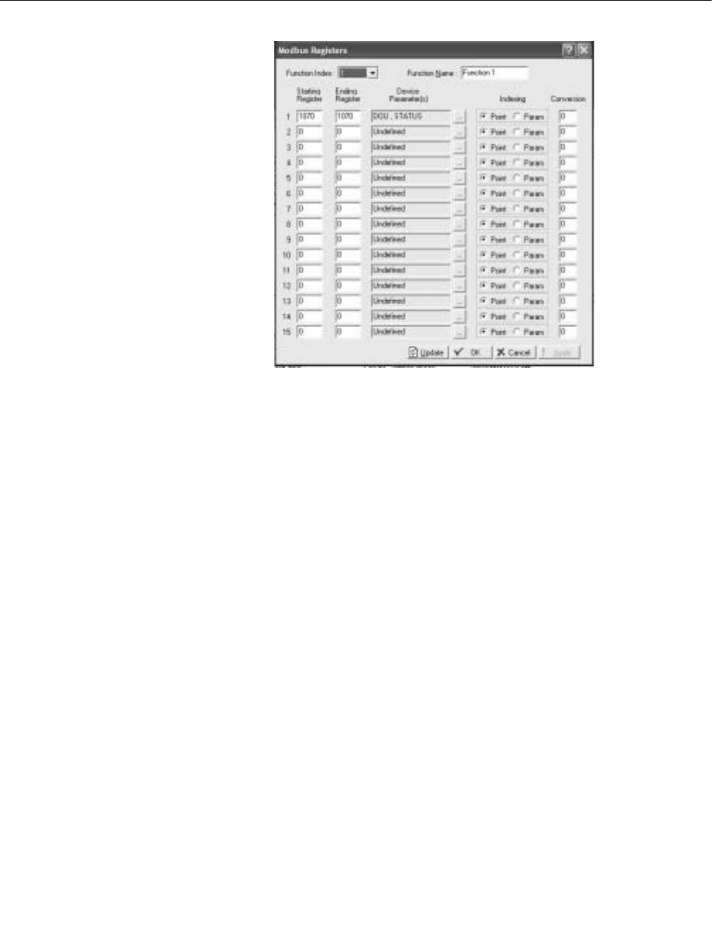
Reference Manual
00809-0100-4832, Rev AA
October 2004
3-51
Rosemount 3095FC
Figure 3-28. Modbus Registers
Configuration Screen
Modbus Conversion Conversion codes convert the data into a format that is compatible to a
Modbus device.
Select the Conversion field, on the Modbus Registers or Modbus History
screen, (Configure > Modbus > Modbus Register) to specify the type of
conversion required, if any, on the data before it is sent to the host or before it
is written to the 3095FC. The conversions are used to account for differences
in data types between the master and slave devices. Table 3-8 lists the
Convert Codes used.
Conversion Codes 65 to 72 allows a four-byte IEEE formatted floating point
number to be sent or received in two Modbus registers with the byte orders
configurable. A check is made to ensure that an even number of registers is
requested, that the Start Register number does not begin in the middle of a
register pair, and that the number of registers does not exceed the number of
registers configured.

Reference Manual
00809-0100-4832, Rev AA
October 2004
Rosemount 3095FC
3-52
Table 3-8. Modbus Conversion
Codes
Convert
Code Description
Slave
Function Definition
0 No Conversion – –
1Float to Integer, Float Scale 1 3, 4 The Float to Integer conversion changes floating point data to an integer for
transmission to the host. The number of the Convert Code specifies which
floating point scaling value is to be used for the conversion
2 Float to Integer, Float Scale 2 3, 4
3Float to Integer, Float Scale 3 3, 4
4 Float to Integer, Float Scale 4 3, 4
5Float to Integer, Float Scale 5 3, 4
6 Float to Integer, Float Scale 6 3, 4
7Float to Integer, Float Scale 7 3, 4
8 Float to Integer, Float Scale 8 3, 4
9 to 16 No Conversion 6, 16 –
17 Integer to Float, Float Scale 1 6, 16 The Integer to Float conversion changes a transmitted integer value to a
floating point value. The number of the Convert Code specifies which floating
point scaling value is to be used for the conversion. If no fractional part is
coming through on conversion from integer to float, use a float conversion that
more closely fits the range of integer to be converted, such as float range 0 to
10 instead of 0 to 1000.
18 Integer to Float, Float Scale 2 6, 16
19 Integer to Float, Float Scale 3 6, 16
20 Integer to Float, Float Scale 4 6, 16
21 Integer to Float, Float Scale 5 6, 16
22 Integer to Float, Float Scale 6 6, 16
23 Integer to Float, Float Scale 7 6, 16
24 Integer to Float, Float Scale 8 6, 16
30 to 32 No Conversion – –
33 Character to Integer 3, 4 The Character to Integer conversion changes a character data type to an
integer for transmitter to the host.
34 Integer to Character 6, 16 The Integer to Character conversion changes a transmitted integer value to a
character data type.
35 Long to Integer 3, 4 The Long to Integer conversion changes a long data type to an integer for
transmission to the host.
36 Integer to Long 6, 16 The Integer to Long conversion changes a transmitter integer value to a long
data type.
39 Float to Integer, No Scaling 3, 4 The Float to Integer conversion changes a floating point data type to an
integer for transmitter to the host.
40 Integer to Float, No Scaling 3, 4, 6, 16 The Integer to Float conversion changes a transmitted integer value to a
floating point data type.
41 Float to Byte, No Scaling 3, 4 The Float to Byte conversion changes a floating point data type to a byte for
transmission to the host.
42 Byte to Float, No Scaling 3, 4, 6, 16 The Byte to Float conversion changes a transmitted byte value to a floating
point data type
43 Float to Long, No Scaling 3, 4 The Float to Long conversion changes a floating point data type to a Long
Integer for transmission to the host.
44 Long to Float, No Scaling 3, 4, 6, 16 The Long to Float conversion changes a transmitted Long Integer value to a
floating point data type.
45 Float to Byte 6, 16 he Float to Byte Unsigned Character conversion changes a transmitted
floating point value to an unsigned character data type.
46 Float to Unsigned Integer 6, 16 The Float to Unsigned Integer conversion changes a transmitted floating point
value to an unsigned integer data type.
47 Float to Unsigned Long 6, 16 The Float to Unsigned Long conversion changes a transmitted floating point
value to an unsigned long data type.
48 No Conversion – –

Reference Manual
00809-0100-4832, Rev AA
October 2004
Rosemount 3095FC
3-53
49 Deadband, Float Scale 1 3, 4, 6, 16 The Deadband to Float Scale conversion changes the Deadband pint data to
an integer for transmission to the host. The number of the Convert Code
specifies which floating point scaling value is to be used for the conversion.
50 Deadband, Float Scale 2 3, 4, 6, 16
51 Deadband, Float Scale 3 3, 4, 6, 16
52 Deadband, Float Scale 4 3, 4, 6, 16
53 Deadband, Float Scale 5 3, 4, 6, 16
54 Deadband, Float Scale 6 3, 4, 6, 16
55 Deadband, Float Scale 7 3, 4, 6, 16
56 Deadband, Float Scale 8 3, 4, 6, 16
57 to 64 No Conversion – –
65 IEEE Floating Point Number 3, 4, 16 Places byte 0 an byte 1 in register xxxxx; bye 2 and bye 3 are placed in
register xxxxx + 1. this places a 4-byte floating point value into two, 2-byte
registers to allow integer values to be transmitted. Code 66 does the same as
Coded 65 regardless of the Byte Order field in the Modbus Configuration
screen. Register xxxxx byte 0, byte 1 register xxxxx + 1 byte 2, byte 3.
66 IEEE Floating Point Number 3, 4, 16
67 IEEE Floating Point Number 3, 4, 16 Code 67 reverses byte 0 and byte 1 order in register xxxxx; reverses byte 2
and byte 3 order in register xxxxx + 1. This places a 4-byte floating point value
into two, 2-byte registers to allow integer values to be transmitter. Code 68
does the same as Code 67 regardless of the Byte Order field in the Modbus
Configuration screen. Register xxxxx byte 1, byte 0 Register xxxxx + 1 byte 3,
byte 2.
68 IEEE Floating Point Number 3, 4, 16
69 IEEE Floating Point Number 3, 4, 16 Code 69 places byte 2 and byte 3 in register xxxxx; byte 0 and byte 1 are
placed in register xxxxx + 1. This places a 4-byte floating point value into two,
2-byte registers to allow integer values to be transmitted. Code 70 does the
same as Code 69 regardless of the Byte Order field in the Modbus
Configuration screen. Register xxxxx byte 2, byte 3 Register xxxxx + 1 byte 0,
byte 1.
70 IEEE Floating Point Number 3, 4, 16
71 IEEE Floating Point Number 3, 4, 16 Code 67 reverses byte 2 and byte 3 order in register xxxxx; reverses byte 0
and byte 1 order in register xxxxx + 1. This places a 4-byte floating point value
into two, 2-byte registers to allow integer values to be transmitter. Code 72
does the same as Code 71 regardless of the Byte Order field in the Modbus
Configuration screen. Register xxxxx + 1byte 1, byte 0.
72 IEEE Floating Point Number 3, 4, 16
73 IEEE Floating Point Number 3, 4, 6, 16 Convert Codes 73 and 74 send the IEEE formatted floating point number as
four bytes with a single register request. Only the byte order is changed:
Function Code 73 loads register xxxxx in byte 2, byte 3, byte 0, byte 1 order.
Function code 74 does the same as Function Code 73 regardless of the Byte
Order field in the Modbus Configuration screen.
74 IEEE Floating Point Number 3, 4, 6, 16
75 to 255 No Conversion – –
Convert
Code Description
Slave
Function Definition

Reference Manual
00809-0100-4832, Rev AA
October 2004
Rosemount 3095FC
3-54
CUSTOM DISPLAYS This section describes the Custom Display option. The Custom Display option
allows the creation of customized “live” displays, loading a display from a disk
file, and monitoring flow and I/O points. Display options are located under the
View menu. The 3095FC stores displays to disk.
New Display A new display must be created while connected to the 3095FC and then
saved either to a disk file or to display memory in the 3095FC. The display
can incorporate “live” data, as well as other information to be conveyed. One
example is a graphical representation of the application that a 3095FC is
monitoring and controlling.
Use the following instructions to create a new display.
1. Select View > Display > New.
2. If the Properties box does not appear, select the Properties button
from the toolbar.
3. Enter the name of the display in the Properties: Form Display Name
field.
4. Select to Enable or Disable the Logical Point Number Selection List.
• When Enabled, enter a Point Type. When selecting a TLP, the
Logical Number (L) comes from the logical listing selection box for
those parameters that have the Point Type (T) match the Point
Type entered in this screen.
• When Disabled, the display is in What You See Is What You Get
(WYSIWYG) mode and the user selects the TLP to view.
5. Place the cursor where the display element is to appear. Right-click
on the mouse and select an element.
• Add Frame - Place like elements in a Frame to group user
selections. Once Frame is in place, drag and drop elements onto
the Frame.
• Add Label - Use labels to mark other elements.
• Add Text Box - Data entry fields.
• Add Check Box - Multiple selection box.
• Add Option Button - Radio button to limit input to a single selection.
NOTE
Create elements in the main Form before dragging and dropping them into a
Frame.
6. Enter or select the desired data in the Properties Form. The items in
the Properties box depend on the added object.
7. Many elements can be created and placed anywhere on the edit
screen. Option buttons should be placed within a frame. Element
properties can be edited at any time.
8. After creating elements to display, click Save to save the display to a
disk file located on the PC or floppy drive. Enter the desired File name
of the disk file, or use the default. The .DSP extension will
automatically be added.

Reference Manual
00809-0100-4832, Rev AA
October 2004
Rosemount 3095FC
3-55
9. Press the Test button to display the screen as it will appear in use.
Use the Update, Autoscan, Stop Scan, Edit, Save, and Close buttons
at the bottom of the screen to perform the following functions:
• Update - Use this button to update all TLP (live data) information
with the current reading from the 3095FC. The message “Reading
Data” appears in the Status Line.
• Apply - Applies changes made to fields in display which display is
not in Autoscan.
• Autoscan - Provides an automatic update on intervals lasting one
to three seconds.
• Stop Scan - Stops Autoscan.
• Edit Display - Change currently selected display.
• Character Set - Show the Character Set currently selected for
building the display. This button toggles between viewing and not
viewing Character Sets. Eight different character sets are
supported: two for upper and lower case alphabetical characters,
and six for various types of graphical characters.
• TLP Box - Enter live data from the Rosemount User Interface
Software or 3095FC. To use the TLP Box, first determine the Point
Type to use as a flow input by highlighting it. Next, select the exact
Logical Number. For example, an Analog Input Point Type that the
user might select is AIN A 2. Finally, select the specific Parameter
to use. For example, an Analog Input is typically Filtered EUs.
Save - If the display is new, this push button saves the current
display to a disk file located on the PC. If the display already
exists, this saves the display back to where it had been saved
before. The extension .DSP (display) is added to the specified file
name. Refer to “Save Displays” on page 3-55.
• Save As - Saves the current display to a disk file under a different
name to a file or to internal Display1 or Display2. The
extension.DSP (display) is applied to the name of the file.
• Close - Close the selected display screen with option to save.
NOTE
Use the mouse or >Alt+F6> keys to move between the buttons. Cut, Copy,
and Paste can also be used when creating custom Displays.
Save Displays After creating a display, store the current display to:
• Disk file located on the PC or floppy drive.
• Display1.
• Display2 (if available in the device).
To save a Display:
1. Click Save and proceed to Step 4. Click Save As to save either to a
file or to display memory.
2. Click To Rosemount User Interface Software or To File.
3. If To Rosemount User Interface Software is selected, select Display1
or Display2.
4. If To File is selected, enter the desired File name of the disk file, or
use the default. The .DSP extension will automatically be added.

Reference Manual
00809-0100-4832, Rev AA
October 2004
Rosemount 3095FC
3-56

Reference Manual
00809-0100-4832, Rev AA
October 2004 Rosemount 3095FC
www.rosemount.com
Section 4 Calibration
Overview . . . . . . . . . . . . . . . . . . . . . . . . . . . . . . . . . . . . . . . page 4-1
Calibrate . . . . . . . . . . . . . . . . . . . . . . . . . . . . . . . . . . . . . . . page 4-1
Verify Calibration . . . . . . . . . . . . . . . . . . . . . . . . . . . . . . . . page 4-6
OVERVIEW Once startup is successful and configuration is complete, it is necessary to
calibrate the 3095FC to meet the requirements of the application. The
following section details the procedure for calibrating the 3095FC and the I/O.
Once calibration is complete the 3095FC can be placed into operation.
NOTE
When the enclosure end caps are unscrewed, local calibration or monitoring
of the 3095FC through its LOI port must be performed in a non-hazardous
area. Performance of these procedures in a hazardous area could result in
personal injury or property damage.
CALIBRATE
3095FC Use the Rosemount User Interface Software to calibrate as follows:
1. Launch the Rosemount User Interface Software and connect to the
3095FC.
2. Select the Meter > Calibration. The current reading displays under
each meter input as the Freeze Value. The 3095FC uses these
values in the flow calculations while calibrating the points.
3. Click Freeze. If necessary, create a calibration file.
4. Isolate the device from the process by opening the by-pass valve on
the valve manifold prior to isolating the device from the process (to
protect the sensor module). This keeps one side of the differential
sensor from being subjected to high pressure while the other side has
no pressure applied. This is required when calibrating either DP or
SP. See Figure 4-1.
5. To calibrate the pressure input, setup the pressure calibrator and
make the necessary connections to the device.
6. To calibrate the temperature input, disconnect the RTD sensor and
connect a decade box (or comparable equipment) to the RTD
terminals of the 3095FC.
7. Click Calibrate under the desired input to calibrate DP, SP, or
Temperature. This displays the Set Zero calibration window.

Reference Manual
00809-0100-4832, Rev AA
October 2004
Rosemount 3095FC
4-2
Figure 4-1. Removing the
Device from Service
8. Apply the low (zero) value. For a pressure input, this would typically
be open to atmosphere.
9. Enter the applied value in the Dead Weight / Tester Value field of the
Set Zero dialog. For SP on an absolute-pressure device, enter the
actual current atmospheric pressure.
NOTE
Apply pressure to both the high and low sides of the transmitter when
calibrating SP.
10. When the displayed Live Reading is stable, click Set Zero to calibrate
the zero reading. The Set Span window then appears
11. Apply the desired high value to the input (the top end of the expected
operating range).
12. Enter the applied value in the Dead Weight / Tester Value field of the
Set Span dialog.
• For SP on an absolute-pressure device, add the actual
atmospheric pressure, such as 300 + 14.73.
13. When the Live Reading is stable, click Set Span to calibrate the high
reading. The window advances to the Set Midpoint 1 window.
14. To perform a two-point calibration, click Done to complete calibration.
15. To calibrate midpoints, apply the desired pressure or temperature and
enter the applied value in the Dead Weight / Tester Value field.
Midpoint can be calibrated in any order.
16. When the Live Reading is stable, click Set Mid 1 to calibrate the
reading. The display advances to the Set Midpoint 2 window.
17. To perform a three-point calibration, click Done to complete
calibration.
18. To calibrate additional midpoints, apply the desired pressure or
temperature and enter the applied value in the Dead Weight / Tester
Value field.
19. When the Live Reading is stable, click Set Mid 2 to calibrate this
reading. The display advances to the Set Midpoint 3 window.
20. To perform a four-point calibration, click Done to complete calibration.
21. To calibrate a third midpoint, apply the desired pressure or
temperature and enter the applied value in the Dead Weight / Tester
Value field.
Bleed Blee
d
High
Pressure
Remains
Shutdown Sequence
1
2
3
Operating
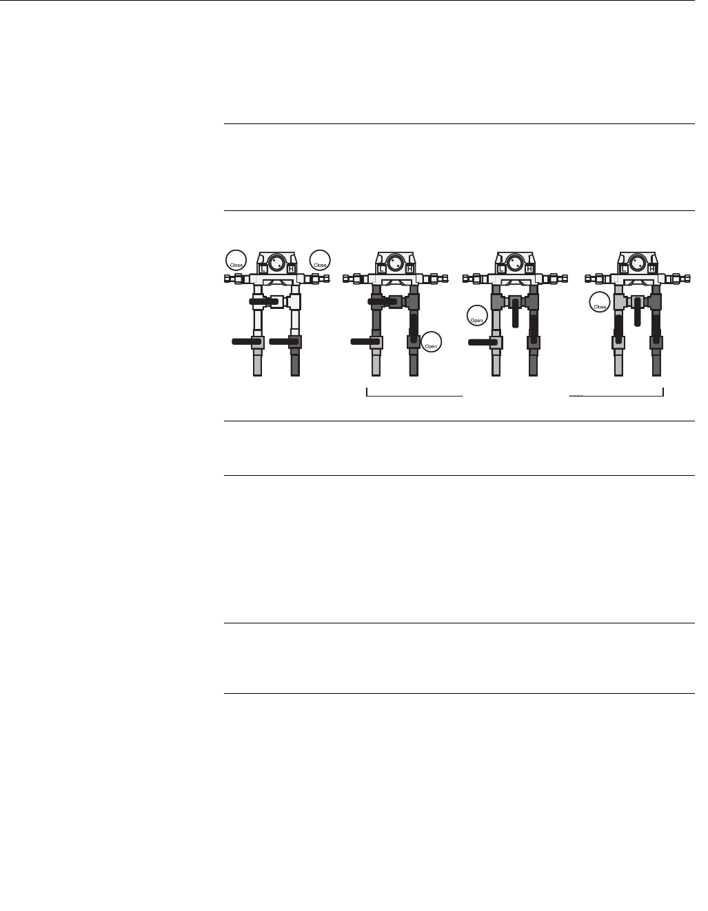
Reference Manual
00809-0100-4832, Rev AA
October 2004
4-3
Rosemount 3095FC
22. When the Live Reading is stable, click Set Mid 3 to calibrate the
reading. The display returns to the Meter Calibration window.
23. When the calibration for a selected point is complete, another input
can be calibrated or complete the calibration. If calibration is
complete return the device to service.
NOTE
Do NOT close the by-pass valve on the valve manifold until after process
pressure has been reapplied, to protect the sensor module. This keeps one
side of the differential sensor from being subjected to high pressure while the
other side has no pressure applied. See Figure 4-2.
Figure 4-2. Returning the
Sensor Module to Service
NOTE:
If calibrating the DP input, refer to “Zero Shift” on page 4-5 before completing
the last step.
24. Finally, click Done to cause the calibration window to close, cancel
freeze values (unfrozen), and enable live readings for use in the flow
calculations. The Event Log records all calibration settings that were
changed.
Analog Input (AI)
Calibration
Select Utilities > AI Calibration Value to view the calibration values for a
specific Analog Input point.
NOTE
Deadweight calibration may be performed from the Calibration tab in the AI
Configuration screen. The Calibration Freeze Value field displays the value
received from the AI when the Update button was last pressed.
Use the drop-down list box to select the AI Point to be viewed. The Tag for
that point displays. Not all of the following parameters apply to each point.
• Raw Value #1 to 5 - Raw Value 1 is the lowest calibrated Raw A/D
input, Raw Value 5 is the highest calibrated Raw A/D input.
• EU Value #1 to 5 - The five calibration settings in Engineering Units
Values, converted from the Raw Values, based on the Low Reading EU
and High Reading EU defined for the point. EU Value 1 is the Zero
value, EU Value 5 is the Span value, and the rest are Midpoint values.
Shutdown Sequence
2
3
4
1b
1a
Pre-Startup
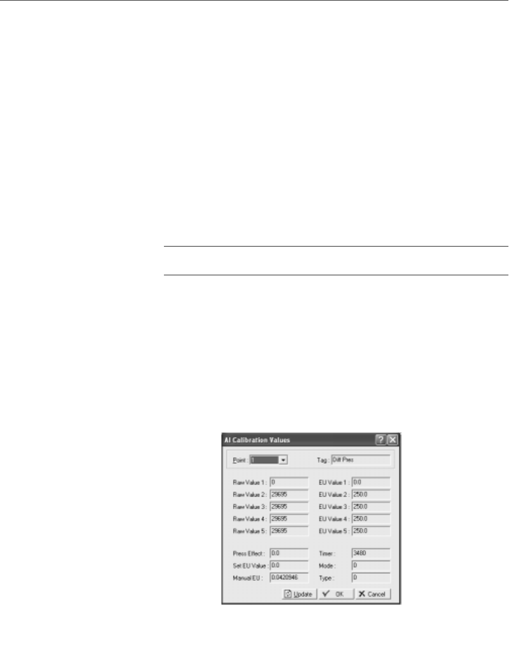
Reference Manual
00809-0100-4832, Rev AA
October 2004
4-4
Rosemount 3095FC
• Press Effect is the Zero Shift adjustment value; it is used as an offset to
the calibrated EU Values to compensate for the working SP effect on a
DP transmitter that was calibrated at atmospheric pressure.
• Set EU Value is the Tester Value specified for the last calibration value
that was set. Manual EU is the Live Reading for the last calibration
value that was set.
• The Timer field shows the last inactivity count-down in seconds
(starting from 3600 seconds) that occurred during the last calibration
session. Had the countdown reached 0, time-out would have taken
place, causing the calibration mode to end.
• Mode indicates:
• 0 = Use Current Calibration
• 1 = Start Calibration
• 2 = Calibrate
• 3 = Restore Previous Calibration
• 4 = Stop Calibration.
NOTE
No event is logged for the Mode Read-Only parameter.
• Type indicates which calibration value is currently being set:
• 0 = Inactive (no value)
•1 = Zero
•2 = Span
• 3 = Midpoint 1
• 4 = Midpoint 2
• 5 = Midpoint 3
•6 = Zero Shift
Figure 4-3. AI Calibration Values
Screen

Reference Manual
00809-0100-4832, Rev AA
October 2004
4-5
Rosemount 3095FC
Calibration Report
The Calibration Report details which parameters were set during calibration.
1. Select View > Calibration Report.
2. Select the Calibration Report to be viewed. The file has the extension
*.800 and is located in the default directory C:/Program
Files/Rosemount User Interface for Windows/Data directory unless
the directory location was changed when the Calibration Report was
created.
3. Click Open.
Calibration Value
Select Utilities > Calibration Value to view the calibration values for a specific
analog input point.
NOTE
Remove/restore the device from/to working pressure during calibration.
Failure to follow recommendations may cause sensor damage.
Zero Shift
To check or adjust for Zero Shift, leave the sensor by-pass valve open (to
simulate a no-flow condition), with either line pressure or a normal operating
SP from the calibrator applied to the sensor. This applies the same pressure
to both sides of the DP diaphragm to give a zero DP reading.
Perform the following steps:
1. Connect the Rosemount User Interface Software to the 3095FC and
run the calibration procedure.
2. Select Meter > Calibration > Freeze.
3. Under the Diff Press input, click Zero Shift to open the Set Zero Shift
window.
4. Verify Reading to determine if a Zero Shift correction is required.
5. If the reading is not zero, click Set Zero Shift to adjust the Zero and
click Done. If the reading is zero, click Done.
6. Click Done to close the calibration window and cancel the freeze
values to begin using live readings for the flow calculations.

Reference Manual
00809-0100-4832, Rev AA
October 2004
4-6
Rosemount 3095FC
VERIFY CALIBRATION Rosemount User Interface Software can verify the calibration to check if the
device requires re-calibration. To verify, perform the following steps:
1. Launch the Rosemount User Interface Software. Connect the
3095FC.
2. Select the Meter > Calibration.
3. Click Freeze. This opens the Meter Calibration window. The current
reading displays under each meter input as the Freeze Value. The
3095FC uses these values in the flow calculations while verifying the
points.
NOTE
Open the by-pass valve on the valve manifold prior to isolating the device
from the process, to protect the sensor module. This keeps one side of the
sensor from being subjected to high pressure while the other side has no
pressure applied. This is required when calibrating either DP or SP.
4. While observing the previous Note, apply the desired pressure setting
to the input.
NOTE
Apply pressure to both the high and low sides of the transmitter when
verifying SP.
5. Click Verify listed under the input to be calibrated.
6. To log the Tester Value and the Live Reading to the Event Log as a
record of the verification, click Log Verify.
7. Click Done.
8. Continue to verify all required pressures/values.
9. When complete, connect the 3095FC back to the process.
NOTE
Do NOT close the by-pass valve on the valve manifold until after process
pressure has been reapplied, to protect the device. This keeps one side of the
differential sensor from being subjected to high pressure while the other side
has no pressure applied.
10. Click Done to close the calibration window, to cancel the freeze
values, and to begin using live readings for the flow calculations.
Figure 4-4. Meter Calibration
Screen

Reference Manual
00809-0100-4832, Rev AA
October 2004 Rosemount 3095FC
www.rosemount.com
Section 5 Troubleshooting and
Maintenance
Backup Configuration Information . . . . . . . . . . . . . . . . . . page 5-1
Communication Errors . . . . . . . . . . . . . . . . . . . . . . . . . . . . page 5-2
Resetting the 3095FC . . . . . . . . . . . . . . . . . . . . . . . . . . . . . page 5-3
After Installing Components . . . . . . . . . . . . . . . . . . . . . . . page 5-4
Replacing the Batteries . . . . . . . . . . . . . . . . . . . . . . . . . . . page 5-5
Changing the Plate . . . . . . . . . . . . . . . . . . . . . . . . . . . . . . . page 5-5
The following tools are required for troubleshooting:
• IBM-compatible PC
• Rosemount User Interface Software
BACKUP
CONFIGURATION
INFORMATION
Perform backup procedure before removing power to the 3095FC for repairs,
troubleshooting, removing or adding components, or upgrades. This
procedure preserves the current flow PC configuration and log data held in
RAM.
NOTE
When installing equipment in a hazardous area, ensure that all components
are approved for use in such areas. Check the product labels. Change
components only in an area known to be non-hazardous. Performing these
procedures in a hazardous area could result in personal injury or property
damage.
To avoid circuit damage when working inside the unit, use appropriate
electrostatic discharge precautions, such as wearing a grounded wrist strap.
1. Log into the Rosemount User Interface Software.
2. Save the configuration in flash memory Click Device > Flags > Save
Flash Memory Configuration. This saves all configuration settings,
including the current states of the flags and calibration values.
3. Select Device > Collect Data. Click OK to save event logs (.evt),
alarm logs (.alm), report data (.det), hourly logs (.pdb), and daily
(.day) logs. Specify the desired file name and path.
4. Backup the 10-minute history file.
5. Select File > Save.
6. Type the desired File name for the backup file.
7. Click Save. The file is saved in the default directory C:/Program
Files/Rosemount/Rosemount User Interface Data, unless the
directory has been changed.

Reference Manual
00809-0100-4832, Rev AA
October 2004
Rosemount 3095FC
5-2
COMMUNICATION
ERRORS
Several events can cause a connection failure:
• If the Direct Connect communication link fails, use the Connect feature
to establish a connection to the 3095FC. The Configuration Tree option
allows the user to change the communications port, time-out settings,
and other variables used when establishing a communications link to
the PC.
• A communications failure can also occur if Rosemount User Interface
Software stands idle for too long and exceeds the timeout value for a
device. In this case, simply log back into Rosemount User Interface
Software using Direct Connect or the Configuration Tree connect
feature.
• Enter an Operator and Password for each user who connects to a
3095FC in the 3095FC security options located under the 3095FC
menu.
Communication Problems
The PC communications options may need to be altered if communicating
problems occur.
1. If not currently active, select 3095FC Directory from the View or
Window menu.
2. Select the desired Station Name of the 3095FC device.
3. Right-mouse click and select Properties.
4. Specified the correct 3095FC Address and 3095FC Group of the
3095FC with which communicate is being established. If
communicating through the LOI port of the device, set the 3095FC
Address to 240 and Group Address to 240, which is the universal
address.
5. Click the Advanced tab.
6. Try increasing the Time Out and/or Tx Delay.
7. Click Apply, and then OK.
8. Click the General tab, and click Connect.
9. If communication problems still occur, try increasing the Number of
Retries field in the Advanced tab screen. Contact an Emerson
Process Management representative for additional assistance.
Debug Communications
Select Utilities > Debug Communications to open a Diagnostics window,
which displays the data bytes (in hex format) sent and received from the
3095FC during any operation. Bytes sent are shown in black; bytes received
are shown in red. Right-click on the display to Copy highlighted data, Clear All
data, or Unselect. Copied data can be pasted in a file for analyzing.

Reference Manual
00809-0100-4832, Rev AA
October 2004
5-3
Rosemount 3095FC
RESETTING THE 3095FC If problems occur that appear to be software related, try resetting with a Warm
Start, Cold Start, or Jumper Reset.
Warm Start The re-initialization is performed by setting a parameter in the Rosemount
User Interface Software Flags. The re-initialization includes the Tasks,
Database, Communication Ports, sensor module, and I/O. It does not change
the current configuration of any parameters.
1. Log into the Rosemount User Interface Software.
2. Connect the PC to the 3095FC.
3. Perform “Backup Configuration Information” on page 5-1.
4. Select 3095FC > Flags
5. Click on Warm Start
6. Apply to save the change.
Cold Start The re-initialization is performed by setting a parameter in the Rosemount
User Interface Software Flags, called Cold Start. The re-initialization includes
the Tasks, Database, Communication Ports, Sensor, I/O, and restoring the
saved configuration, if there is one. It also includes resetting or clearing other
items, based upon the selection made in the Options screen.
1. Log into the Rosemount User Interface Software.
2. Connect the PC to the 3095FC.
3. Perform “Backup Configuration Information” on page 5-1.
4. Select 3095FC > Flags.
5. Click on Cold Start.
6. Apply to save the change.
Jumper Reset The Reset jumper located on the LCD (if installed) or on the Battery Charger
Board can be used to perform a special type of cold start. The jumper permits
a power-up reset to re-establish a known operating point. It includes
re-initializing the Communication Ports to the factory default configuration.
The cold start does not include any of the clearing options available in a Cold
Start performed using Rosemount User Interface Software.
NOTE:
This type of reset restores the communications ports to the factory
configuration defaults. Some user-entered configuration parameters may be
lost. Therefore, back up any required data before performing the reset.
1. Perform “Backup Configuration Information” on page 5-1.
2. Unscrew the front end cap cover (LCD end).
3. Place the reset jumper (located on the LCD if installed or on the
Battery Charger Board at J2) in the Reset position.
4. Cycle the power.
5. Remove the reset jumper and install it in the normal (NORM) position.
6. Replace the front end cap cover (LCD end).
7. Perform the “After Installing Components” on page 5-4.
The reset procedure loads the factory default values into the communication
ports.

Reference Manual
00809-0100-4832, Rev AA
October 2004
5-4
Rosemount 3095FC
AFTER INSTALLING
COMPONENTS
After removing power to the 3095FC and installing components as needed,
perform the following steps to start the 3095FC and reconfigure the data.
NOTE
Ensure all input devices, output devices, and processes remain in a safe state
upon restoring power. An unsafe state could result in property damage.
When installing equipment in a hazardous area, ensure that all components
are approved for use in such areas. Check the product labels. Change
components only in an area known to be non-hazardous. Performing these
procedures in a hazardous area could result in personal injury or property
damage.
1. Reconnect power to the 3095FC by inserting the CHG+ / CHG-
power terminal.
2. Launch Rosemount User Interface Software, log in, and connect to
the 3095FC.
3. Verify that the configuration is correct. If it is not, continue by
configuring the required items. If major portions or the entire
configuration needs to be reloaded, perform the remaining steps.
4. Select File > Download.
5. From the Open dialog box, select the backup configuration file (has
extension *.800).
6. Select the portions of the configuration to download (restore).
7. Click Download to restore the configuration.

Reference Manual
00809-0100-4832, Rev AA
October 2004
5-5
Rosemount 3095FC
REPLACING THE
BATTERIES
The battery pack contains three D-size lead-acid batteries providing 2.5
Amp-hours of current at 6.2 volts nominal.
NOTE
When installing equipment in a hazardous area, ensure that all components
are approved for use in such areas. Check the product labels. Change
components only in an area known to be non-hazardous. Performing these
procedures in a hazardous area could result in personal injury or property
damage. To avoid circuit damage when working inside the unit, use
appropriate electrostatic discharge precautions, such as wearing a grounded
wrist strap.
To replace the battery pack.
1. Unscrew the front end cap cover.
2. Remove the LCD display (if applicable).
3. Place the power jumper (located at J1 on the Battery Charger Board)
in the OFF position.
4. Remove the four screws from the Battery Charger Board.
5. Remove the ribbon cable from the Battery Charger Board to the
Backplane Board.
6. Remove the Battery Charger Board.
7. Replace the Battery Charger Board.
8. Replace the ribbon cable from the Backplane Board to the Battery
Charger Board.
9. Replace the four screws from the Battery Charger Board.
10. Reinstall the LCD display (if applicable).
11. Place the power jumper in the ON position.
12. Replace the front end cap cover.
CHANGING THE PLATE The Plate Change option allows the user to change the size of an orifice plate.
1. Select Plate Change from the Meter menu to record an orifice plate
change.
2. Select Yes if the plate change occurs during flowing conditions. Click
No for non-flowing conditions.
3. After selecting the appropriate Meter ID, click Freeze. If performing
the Plate Change under flowing conditions, the dialog box shows the
Freeze Value of each meter input (for purposes of data logging) while
the change is being made. All I/O values are held in Manual mode at
the current value. The values are returned to an active state after
clicking OK in the Plate Change dialog box.
4. Enter the new exact size for the Orifice Diameter (Inches or
Millimeters) in the new plate.
5. Click Apply to record the change creating a record in the Event Log
and restarts the flow calculation using the new orifice size data.
6. Click OK.

Reference Manual
00809-0100-4832, Rev AA
October 2004
5-6
Rosemount 3095FC

Reference Manual
00809-0100-4832, Rev AA
October 2004 Rosemount 3095FC
www.rosemount.com
Appendix A Specifications and Reference
Data
Specifications . . . . . . . . . . . . . . . . . . . . . . . . . . . . . . . . . . . page A-1
Dimensional Drawings . . . . . . . . . . . . . . . . . . . . . . . . . . . . page A-7
Ordering Information . . . . . . . . . . . . . . . . . . . . . . . . . . . . . page A-9
Options . . . . . . . . . . . . . . . . . . . . . . . . . . . . . . . . . . . . . . . . page A-11
Accessories . . . . . . . . . . . . . . . . . . . . . . . . . . . . . . . . . . . . . page A-11
SPECIFICATIONS
Functional
Specifications
Service
Gas or liquid
Input
Single input for a 2- or 3-wire RTD
Differential Sensor
Limits
• Code 2: –250 to 250 inH2O (-622,70 to 622,7mbar)
• Code 3: –1000 to 1000 inH2O (-2,49 to 2,49 bar)
Absolute Sensor
Limits
• Code 3: 0 to 800 psia (0 to 55158,1 mbar)
• Code 4: 0 to 3,626 psia (0 to 250,0 bar)
Gage Sensor
Limits
•Code C: 0 to 800 psig (0 to 55158,1 bar)
• Code D: 0 to 3,626 psig (0 to 250,0 bar)
Over Pressure Limit
0 psia to two times the absolute pressure sensor range with a maximum of
3,626 psia.
Static Pressure Limit
Operates within specifications between static line pressures of 0.5 psia and
the URL of the absolute pressure sensor.

Reference Manual
00809-0100-4832, Rev AA
October 2004
Rosemount 3095FC
A-2
Power
• Transmitter: operates on terminal voltage of 8 - 28 Vdc
• Input current: 5mA nominal, 9.5 mA at 100% duty cycle (battery charging
not included)
• Internal battery: rechargeable, Nominal 6.2 Vdc (2.5 Amp/hr)
• Maximum power consumption: 19 watts
• Solar panel input: nominal 8 V to 200 mA
• Solar panel output: 2 watts, 9 V nominal
• External charging input: 12 Vdc max (8 - 10 Vdc nominal)
RS-485 Signal Wiring
2-wire half-duplex RS-485 MODBUS with 8 data bits, 1 stop bit,
and no parity
Bus Terminations
Standard RS-485 bus terminations required per EIA-485.
Failure Mode Alarm
If self-diagnostics detect a gross transmitter failure, non-latched status bits
are set in the transmitter alarm registers.
Humidity Limits
0–95%, non condensing
Communications
User Interface: EIA-232 (RS-232C) format
Baud Rate: 600 to 19200 bps User selectable
Host: RS-485 / RS-232
Rosemount User Interface Software and Hardware Requirements:
• IBM-compatible PC
• 1 MB of RAM
• Pentium-grade processor: 233 MHz or faster
• Microsoft Windows 98 or higher operating system
• CD-ROM drive
Temperature Limits
Process (at transmitter isolator flange for atmospheric pressures and above):
• –40 to 212 °F (–40 to 100 °C)
• Inert fill sensor: 0 to 185 °F (-18 to 85 °C).
• Process temperatures above 185 °F (85 °C) requires derating the ambient
limits by a 1.5:1 ratio.
Ambient:
• –40 to 167 °F (–40 to 75 °C)
• with integral meter: -4 to 167 °F (-20 to 75 °C)
Storage:
• –50 to 185 °F (–46 to 85 °C)
• with integral meter: -40 to 185 °F (-40 to 85 °C)

Reference Manual
00809-0100-4832, Rev AA
October 2004
A-3
Rosemount 3095FC
Turn-on Time
Process variables will be within specifications less than 4 seconds after power
is applied to transmitter.
Real Time Clock
• Year /month / day / hour / minute / second
• Battery Packed
Serial Card – EIA-232D Card
Standards
• Meets EIA-232 standard for single-ended data transmission over
distances of up to 50 ft (15 m).
Data Rate
• Selectable from 1200 to 19200 bps
Format
• Asynchronous, 7 or 8-bit (software selectable with full handshaking)
Parity
• None, odd, or even (software selectable)
Performance
Specifications
(Zero-based spans, reference conditions, silicone oil fill, 316 SST isolating
diaphragms, and digital trim values equal to the span end points.)
Differential Pressure
Range 2
• 0–2.5 to 0–250 inH2O (0–6,2 to 0–622,7 mbar)
(100:1 rangeability is allowed)
Range 3
• 0–10 to 0–1000 inH2O(0–0,025 to 0–2,49 bar)
(100:1 rangeability is allowed)
Accuracy (including Linearity, Hysteresis, Repeatability)
• ±0.075% of span for spans from 1:1 to 10:1 URL for spans less than 10:1
rangedown
Ambient Temperature Effect per 50 °F (28 °C)
• ±(0.025% URL + 0.125% span) spans from 1:1 to 30:1
• ±(0.035% URL + 0.175% span) spans from 30:1 to 100:1
Static Pressure Effects
• Zero error = ±0.05% of URL per 1,000 psi (68.9 bar)
• Span error = ±0.20% of reading per 1,000 psi (68.9 bar)
Stability
• ±0.125% URL for five years for ±50 °F (28 °C) ambient temperature
changes, and up to 1000 psi (6,9MPa) line pressure.
Absolute/Gage Pressure (AP)(GP)
Range 3 (absolute), Range C (gage)
• 0–8 to 0–800 psi (0–0,55 to 0–55,2 bar)
(100:1 rangeability is allowed)
Accuracy 0.03 0.0075 URL
Span
--------------
+ % of span=

Reference Manual
00809-0100-4832, Rev AA
October 2004
Rosemount 3095FC
A-4
Range 4 (absolute)/ Range D (gage)
• 0–36.26 to 0–3,626 psi (0–2,5 to 0–250,0 bar)
(100:1 rangeability is allowed)
Accuracy (including Linearity, Hysteresis, Repeatability)
• ±0.075% of span for spans from 1:1 to 6:1 of URL
• For spans less than 6:1 rangedown,
Ambient Temperature Effect per 50 °F (28 °C)
• ±(0.05% URL + 0.125% of span) spans from 1:1 to 30:1
±(0.06% URL – 0.175% of span) spans from 30:1 to 100:1
Stability
• ±0.125% URL for five years for ±50 °F (28 °C) ambient temperature
changes, and up to 1000 psi (6,9MPa) line pressure.
Process Temperature (RTD)
Specification for process temperature is for the transmitter portion only.
Sensor errors caused by the RTD are not included. The transmitter is
compatible with any PT100 RTD conforming to IEC 751 Class B, which has a
nominal resistance of 100 ohms at 0 °C and ∝ = 0.00385. Examples of
compatible RTDs include the Rosemount Series 68 and 78 RTD Temperature
Sensors.
Sensing Range
• –40 to 212 °F (–40 to 100 °C)
Accuracy (including Linearity, Hysteresis, Repeatability)
• ±1.0 °F (0.56 °C)
Ambient Temperature Effects per 50 °F (28 °C)
• ±0.90 °F (0.50 °C) for process temperatures from –40 to 212 °F (–40 to
100°C)
Stability
• ±1.0 °F (0.56 °C) for one year
Physical Specifications Electrical Connections
½–14 NPT 3/4-14 NPT, CM 20, PG-13.5
RTD Process Temperature Input:
100-ohm platinum RTD per IEC-751 Class B
Process Connections
• Transmitter: ¼–18 NPT on 21/8-in. centers
• RTD: RTD dependent (see ordering information)
Battery
Lead-acid
Accuracy 0.03 0.0075 URL
Span
--------------
+ % of span=

Reference Manual
00809-0100-4832, Rev AA
October 2004
A-5
Rosemount 3095FC
Process Wetted Parts
Isolating Diaphragms
• 316L SST or Hastelloy C-276®
Drain/Vent Valves
• 316 SST or Hastelloy C®
Flanges
• Plated carbon steel, 316 SST, or Hastelloy C
Wetted O-rings
• Glass-Filled TFE
Non-Wetted Parts
Electronics Housing
• Low copper aluminum
Bolts
• Plated carbon steel per ASTM A449, Grade 5; or austenitic 316 SST
Fill Fluid
• Silicone oil
• Inert oil (available for gage pressure ranges only)
Paint
• Polyurethane
O-rings
• Buna-N
Weight
Components
Weight in lb. (kg)
3095FC
3095 Transmitter 12.4 (5.6)
LCD Meter 0.5 (0.2)
SST Mounting Bracket 1.0 (0.5)
Battery / Solar Panel 2.0 (0.9)
Battery Backup 1.3 (0.6)

Reference Manual
00809-0100-4832, Rev AA
October 2004
Rosemount 3095FC
A-6
Memory Specifications Programmable Memory
2 MB x 8 flash EPROM
Data Memory
512 kB 5 RAM
Boot Memory
128 kB flash EPROM
Data Logging
Archival
• 60 days of 10 minutes data
• 35 days of hourly data
• 35 days of daily data
• minimum/maximum values for a single data
Memory Logging
• 240 alarms before rollover
• 240 events before rollover
Flow Specifications Flow Calculation:
• Computed in accordance with ANSI/API 2530-92 (AGA 3, 1992), API 14.2
(AGA 8, 1992), and API 21.1. Detail Gross I, Gross II.

Reference Manual
00809-0100-4832, Rev AA
October 2004
A-7
Rosemount 3095FC
DIMENSIONAL DRAWINGS
3095FC
Side View Front View
Dimensions are in inches (millimeters)
3095FC with Solar Panel Assembly
Side View Front View
Dimensions are in inches (millimeters)
7.50 (191)
10.71 (272)
Terminal
Block
3/4-in.–14 NPT
Conduit Plug
Meter Cover
Optional
1.2 (30.5)
Clearance
Required to
remove cover
6.4 (163)
Solar Panel
Assembly
(optional)
17 (732)
10.71 (272)
6.24 (159)
4.48 (114)
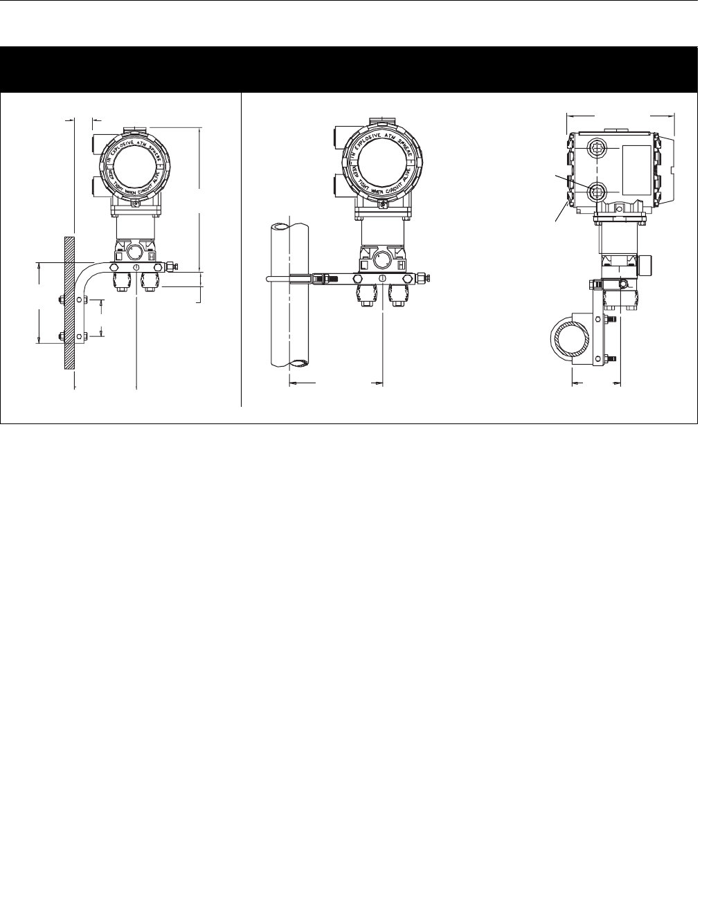
Reference Manual
00809-0100-4832, Rev AA
October 2004
Rosemount 3095FC
A-8
Mounting Configurations for 3095FC Transmitter
Panel Mount Pipe Mount
Dimensions are in inches (millimeters)
10.25
(260)
1.10 (28)
5.26 (134)
2.81 (71)
6.40
(163)
2.0 (51)
6.40 (163) 3.70
(93)
3095/3095J04E, 3095J04F, 3095J04G
7.50 (191)
3/4–14 NPT
Conduit Plug
Terminal Block

Reference Manual
00809-0100-4832, Rev AA
October 2004
A-9
Rosemount 3095FC
ORDERING INFORMATION
• Available
— Not available
3095FB 3095FC
Code Product Description
3095F MultiVariable Transmitter • •
Code Output
BProcess Variable Measurement: Modbus RS-485 • —
CProcess Variable Measurement: Mass Flow and Data Logging: Modbus RS-485 — •
Code Differential Pressure Range
20 – 2.5 to 0 – 250 inH2O (0 – 6,23 to 0 – 623 mbar) • •
30 – 10 to 0 – 1000 inH2O (0 – 0,025 to 0 – 2,49 bar) • •
Code Absolute/Gage Pressure Ranges
30–8 to 0–800 psia (0–0,55 to 0–55,1 bar) ••
40–36.26 to 0–3,626 psia (0–2,5 to 0–250 bar) • •
C0–8 to 0–800 psig (0–0,55 to 0–55,1 bar) ••
D0–36.26 to 0–3,626 psig (0–2,5 to 0–250 bar) • •
Code Isolator Material Fill Fluid
A316L Stainless Steel (SST) Silicone • •
B(1) Hastelloy C-276 Silicone • •
J(2) 316L SST Inert • •
K(1)(2) Hastelloy C-276 Inert • •
Code Flange Style Material
ACoplanar CS • •
BCoplanar SST • •
CCoplanar Hastelloy C(2) ••
0None (Required for Option Codes S3 or S5) SST • •
Code Drain/Vent Material
ASST ••
C(1) Hastelloy C • •
0None (Required for Option Codes S3 or S5) • •
Code O-ring
1Glass-filled TFE • •
Code Process Temperature Input (RTD ordered separately)
0No RTD Cable(3) • •
1RTD Input with 12 ft. (3.66 m) of Shielded Cable • —
2RTD Input with 24 ft. (7.32 m) of Shielded Cable • —
3RTD Input with 12 ft. (3.66 m) of Armored, Shielded Cable • —
4RTD Input with 24 ft. (7.32 m) of Armored, Shielded Cable • —
7RTD Input with 75 ft. (22.86 m) of Shielded Cable • —
8RTD Input with 75 ft. (22.86 m) of Armored, Shielded Cable • —
ARTD Input with 12 ft. (3.66 m) of CENELEC Flameproof Cable • —
BRTD Input with 24 ft. (7.32 m) of CENELEC Flameproof Cable • —
CRTD Input with 75 ft. (22.86 m) of CENELEC Flameproof Cable • —
Code Transmitter Housing Material Conduit Entry Size
APolyurethane-covered Aluminum 1/2–14 NPT • Adapter
EPolyurethane-covered Aluminum 3/4–14 NPT — •
BPolyurethane-covered Aluminum M20 x 1.5 (CM20) • Adapter
CPolyurethane-covered Aluminum PG 13.5 •Adapter
JSST 1/2–14 NPT • —
KSST M20 x 1.5 (CM20) • —
LSST PG 13.5 • —

Reference Manual
00809-0100-4832, Rev AA
October 2004
Rosemount 3095FC
A-10
Code Terminal Block
AStandard •—
BWith Integral Transient Protection • •
CCE MARK / Compliant with EMC – Transient Protection Included • —
Code Meter
0None • •
1LCD Meter • •
Code Bracket
0None ••
1Coplanar SST Flange Bracket for 2-in. Pipe or Panel Mount, SST Bolts • •
2Traditional Flange Bracket for 2-in. Pipe Mounting, CS Bolts • •
3Traditional Flange Bracket for panel Mounting, CS Bolts • •
4Traditional Flange Flat Bracket for 2-in. Pipe Mounting, CS Bolts • •
5Traditional Flange Bracket for 2-in. Pipe Mounting, SST Bolts • •
6Traditional Flange Bracket for panel Mounting, SST Bolts • •
7Traditional Flange Flat Bracket for 2-in. Pipe Mounting, SST Bolts • •
8SST Traditional Flange Bracket for 2-in. Pipe Mounting, SST Bolts • •
9SST Traditional Flange Flat Bracket for 2-in. Pipe Mounting, SST Bolts • •
Code Bolts
0Carbon Steel bolts • •
1Austenitic 316 SST bolts • •
NNone (required for Options code S5) • •
Code Product Certifications
0None • •
AFactory Mutual (FM) Explosion-Proof • —
CCanadian Standards Associate (CSA) Explosion Proof • —
H ATEX Flame-proof • —
MCanadian Standards Association (CSA) U.S. and Canada Explosion-Proof — •
Code Engineered Measurement Solution (EMS)
NProcess Variable Measurement: MODBUS • —
C(3) Mass Flow with Process Variable Measurement and Data Logging: MODBUS — •
Code Options
S5 Assemble to 305 Integral Manifold (requires integral manifold model number) • •
C1 Custom Flow Configuration (requires completed Configuration Data Sheet (see document number
00813-0100-4716))
• •
A3 Mast with Solar Panel Assembly: includes 12 Vdc Batteries — •
P1 Hydrostatic Testing • •
P2 Cleaning for Special Services ••
Q4 Calibration Certificate • •
Q8 Material Traceability Certification per EN 10204 3.1B • •
DF(4) 1/2–14 NPT Flange Adapter, Carbon Steel, Stainless Steel, Hastelloy C • •
A1 Additional RS-232 Communication Board — •
A2 12 Vdc System with Batteries — •
Typical Model Number: 3095F B 2 3 A B A 1 1 A B 0 1 0 A N
(1)
Materials of Construction meet NACE material recommendation per MR 01-75. Environmental limits apply to certain materials. Consult standard for details.
(2) Only available with C or D Gage Sensor Modules.
(3) Required for 3095FC.
(4) Material determined by Flange Style material selection.
• Available
— Not available
3095FB 3095FC

Reference Manual
00809-0100-4832, Rev AA
October 2004
A-11
Rosemount 3095FC
OPTIONS
Standard Configuration Unless otherwise specified, the transmitter is shipped as follows:
Custom Configuration
(Option Code C1)
If Option Code C1 is ordered, the user-specified information for the 3095F
Modbus Transmitter in addition to the standard configuration parameters are
factory configured.
Message, descriptor, slave address, baud rate, upper and lower trim points for
each process variable, damping for each process variable, units for each
process variable, upper and lower operation limits. Unspecified parameters
will remain at the factory default settings.
Tagging
Three customer tagging options are available:
• Standard SST tag is wired to the transmitter. Tag character height is 0.125
in. (3,18 mm),
85 characters maximum.
• Tag may be permanently stamped on transmitter nameplate upon request.
Tag character height is 0.0625 in. (1,59 mm),
65 characters maximum.
• Tag may be stored in transmitter memory. Software tag is left blank unless
specified.
• Software tag is left blank unless specified.
Optional 305 Integral Manifolds
The Rosemount 3095FC Transmitter with 305RC (or 305AC, 305BC) Integral
Manifold are fully assembled, calibrated, and seal tested by the factory. Refer
to PDS 00813-0100-4733 for additional information.
ACCESSORIES Rosemount User Interface Software Packages
The Rosemount User Interface Software package is available with or without
the converter and connecting cables. All configurations are packaged
separately.
Windows 98 or higher
3095FC
• Part Number 03095-5136-0001: Windows User Interface Software–Single
PC License, and Cable.
• Part Number 03095-5135-0001: Windows User Interface Software–Single
PC License.
• Part Number 03095-5135-0002: Windows User Interface Software– Site
License.
• Part Number 03095-5106-0003: 10 foot (3.05 m) 9-pin Serial Cable
Engineering units:
Differential inH2O
Absolute/gage psi (all ranges)
Output: Modbus RTU protocol signal
Flange type: Specified model code option
Flange material: Specified model code option
O-ring material: Specified model code option
Drain/vent: Specified model code option
Flow Configuration Parameters: Factory default
Software tag: (Blank)

Reference Manual
00809-0100-4832, Rev AA
October 2004
Rosemount 3095FC
A-12

Reference Manual
00809-0100-4832, Rev AA
October 2004 Rosemount 3095FC
www.rosemount.com
Appendix B Product Certifications
Approved Manufacturing Locations . . . . . . . . . . . . . . . . . page B-1
European Directive Information . . . . . . . . . . . . . . . . . . . . page B-1
Hazardous Locations Certifications . . . . . . . . . . . . . . . . . page B-1
APPROVED
MANUFACTURING
LOCATIONS
Rosemount Inc. — Chanhassen, Minnesota USA
EUROPEAN DIRECTIVE
INFORMATION
The EC declaration of conformity for all applicable European directives for this
product can be found on the Rosemount website at www.rosemount.com. A
hard copy may be obtained by contacting our local sales office.
ATEX Directive (94/9/EC)
Emerson Process Management complies with the ATEX Directive.
European Pressure Equipment Directive (PED) (97/23/EC)
3095F_2/3,4/D Flow Transmitters — QS Certificate of Assessment - EC
No. PED-H-20 Module H Conformity Assessment
All other 3095_ Transmitters/Level Controller — Sound Engineering
Practice
Transmitter Attachments: Process Flange - Manifold — Sound
Engineering Practice
Electro Magnetic Compatibility (EMC) (89/336/EEC)
3095F Flow Transmitters — EN 50081-1: 1992; EN 50082-2:1995; EN
61326-1:1997 – Industrial
HAZARDOUS
LOCATIONS
CERTIFICATIONS
North American Certifications
2, Groups A, B, C, and D. Install per Rosemount drawing 03095-1025.
Canadian Standards Association (CSA) Approvals
MExplosion-Proof for Class I, Division 1, Groups C and D. Optional solar
panel: mast option: Explosion-Proof for Class I, Division 2, Groups A, B,
C, D, and T3. CSA Enclosure Type 4.
ISSeP

Reference Manual
00809-0100-4832, Rev AA
October 2004
Rosemount 3095FC
B-2

Reference Manual
00809-0100-4832, Rev AA
March 2004 Rosemount 3095FC
www.rosemount.com
Appendix C Rosemount User
Interface Software
Overview . . . . . . . . . . . . . . . . . . . . . . . . . . . . . . . . . . . . . . . page C-1
Point Type Parameter Definitions . . . . . . . . . . . . . . . . . . . page C-1
OVERVIEW To configure the 3095FC, you must be familiar with the structure of the
database. The database is broken into individual parameters and each
database parameter is uniquesly associated by Parameter Number and Point
Type.
POINT TYPE
PARAMETER
DEFINITIONS
A list of all Point Types is provided in Table 3 1 on page 3-1. For each of the
configurable point types (0 through 59), a parameter table is given in Table 3 5
through Table 3 48. Note that the parameter tables each have a point type
name and five columns:
Parameter # - Identifies the specific parameter associated with the Point
Type.
Read-Write - Indicates if the parameter can be read and written to (R/W)
or if the parameter is read-only (R/O).
Data Type - Table C-1 defines the Data Types found in the parameters
table.
Table C-1. Data Types
Length - The byte length of the parameter is indicated in this column.
Description - A brief description of each parameter is provided in this
column.
Data Type Definition Byte Length
AC ASCII character (groups of 10, 20, or 30 characters) 1 per character
BIN Binary 1
FLP Floating Point - IEEE Format 4
INT 8, 16, 32 Signed Integer - number of bits follows 1, 2, or 4
N/A Not applicable –
TLP Point Type, Logical or Point Number, and Parameter
Number
3
UINT 8, 16, 32 Unsigned Integer - number of bits follows 1, 2, or 4

Reference Manual
00809-0100-4832, Rev AA
March 2004
Rosemount 3095FC
C-2
Point Type 0 Information Table 3 5 lists the parameters for the Configurable Opcode Point Type found
in the 3095FC. The parameters for this Point Type consist of a sequence
number and 44 device parameter identifications (Point Type, Logical Number,
and Parameter Number - TLP). After the TLPs have been configured in Point
Type 0:
• Opcodes 10 and 11 can be used to read and write data directly without
specifying the Point Type, Logical Number, or Parameter Number.
• Opcodes 180 and 181 can be used to read and write the parameter
data and do not include the parameter definition.
Table C-2. Point Type 0 - Configurable Opcode
Parameter
Number Read-Write Data Type Length Description
0 R/W FLP 4 Sequence / Revision Number
1R/W TLP 3Data 1
2 R/W TLP 3 Data 2
3R/W TLP 3Data 3
4 R/W TLP 3 Data 4
5R/W TLP 3Data 5
6 R/W TLP 3 Data 6
7R/W TLP 3Data 7
8 R/W TLP 3 Data 8
9R/W TLP 3Data 9
10 R/W TLP 3 Data 10
11 R/W TLP 3Data 11
12 R/W TLP 3 Data 12
13 R/W TLP 3Data 13
14 R/W TLP 3 Data 14
15 R/W TLP 3Data 15
16 R/W TLP 3 Data 16
17 R/W TLP 3Data 17
18 R/W TLP 3 Data 18
19 R/W TLP 3Data 19
20 R/W TLP 3 Data 20
21 R/W TLP 3Data 21
22 R/W TLP 3 Data 22
23 R/W TLP 3Data 23
24 R/W TLP 3 Data 24
25 R/W TLP 3Data 25
26 R/W TLP 3 Data 26
27 R/W TLP 3Data 27
28 R/W TLP 3 Data 28
29 R/W TLP 3Data 29
30 R/W TLP 3 Data 30
31 R/W TLP 3Data 31
32 R/W TLP 3 Data 32
33 R/W TLP 3Data 33
34 R/W TLP 3 Data 34
35 R/W TLP 3Data 35
36 R/W TLP 3 Data 36
37 R/W TLP 3Data 37
38 R/W TLP 3 Data 38

Reference Manual
00809-0100-4832, Rev AA
March 2004
C-3
Rosemount 3095FC
Device Point Types The tables in the rest of this section list the parameters for each of the Point
Types.
Table C-3. Point Type 3 - Analog Input
39 R/W TLP 3Data 39
40 R/W TLP 3 Data 40
41 R/W TLP 3Data 41
42 R/W TLP 3 Data 42
43 R/W TLP 3Data 43
44 R/W TLP 3 Data 44
Parameter
Number Read-Write Data Type Length Description
Parameter
Number
Read-
Write Data Type Length Description Abbr.
0 R/W AC 10 Point Tag Identification TAG
1 R/W AC 10 Units UNITS
2 R/W UINT 16 2 Scan Period (50 millisecond intervals) SCANPR
3 R/W UINT 16 2Filter (50 millisecond intervals) FILTER
4 R/W INT 16 2 Adjusted A/D 0% MINRAW
5 R/W INT 16 2Adjusted A/D 100% MAXRAW
6 R/W FLP 4 Low Reading EU MINEU
7 R/W FLP 4High Reading EU MAXEU
8 R/W FLP 4 Low Alarm EU LOAL
9 R/W FLP 4High Alarm EU HIAL
10 R/W FLP 4 Low Low Alarm EU LOLOAL
11 R/W FLP 4Hi Hi Alarm EU HIHIAL
12 R/W FLP 4 Rate Alarm EU RATEAL
13 R/W FLP 4Alarm Deadband ALDBND
14 R/W FLP 4 Filtered EUs EU
15 R/W BIN 1Mode:
Bit 7 – Manual Mode
0 = Normal Scan
1 = Manual Scan
Bit 6 – RBX on Set
0 = Disabled
1 = Active
Bit 5 – RBX on Clear
0 = Disabled
1 = Active
Bit 4 – Alarm Enable
0 = Disabled
1 = Log Alarm
Bit 3 – Not Used
Bit 2 – Not Used
Bit 1 – Clipping
0 = Disable
1 = Clipping Enable
Bit 0 – Fault Handling
0 = Retain Last EU Value
1 = Set EU Value to Fault EU Value (Parameter 19)
BIN

Reference Manual
00809-0100-4832, Rev AA
March 2004
Rosemount 3095FC
C-4
Table C-4. Point Type – AGA Flow Parameters
16 R/O BIN 1 Alarm Code:
Bit 7 – Manual Mode
Bit 6 – Point Fail
Bit 5 – Not Used
Bit 4 – Rate Alarm
Bit 3 – High High Alarm
Bit 2 – High Alarm
Bit 1 – Low Low Alarm
Bit 0 – Low Alarm
ALARM
17 R/O INT 16 2Raw A/D Input CURRAW
18 R/O UINT 16 2 Actual Scan Time SCAN
19 R/W FLP 4Fault EU Value FAULTVAL
Parameter
Number
Read-
Write Data Type Length Description Abbr.
Parameter
Number
Read-
Write Data Type Length Description Abbr.
0 R/W AC 10 Point Tag Identification TAG
1 R/W FLP 4Latitude LAT
2 R/W FLP 4 Elevation ELAVTN
3 R/W BIN 1Calculation Method:
Bit 7 – Manual Mode
0 = Normal
1 = Manual
Bit 6 – RBX Set
0 = Disabled
1 = Active
Bit 5 – RBX on Clear
0 = Disabled
1 = Active
Bit 4 – ALM Enable
0 = Disabled
1 = Log Alarms
Bit 3 – US or Metric
0 = US Units
1 = Metric Units
Bit 2 – AGA3 Algorithm
1 = 1992 Algorithm
Bit 1 – Flow Calculation Method
0 = AGA3
Bit 0 – Compressibility Method
1 = AGA8
METHOD

Reference Manual
00809-0100-4832, Rev AA
March 2004
C-5
Rosemount 3095FC
4 R/W BIN 1 AGA Configuration – Options:
Bit 7 – Log Methane Adjustment
0 = Yes
1 = No
Bit 6 – Heating Value
0 = Mass
1 = Volume Basis
Bit 5 – Gravitational Acceleration
0 = Calculate
1 = Enter Acceleration
Bit 4 – Heating Capacity
0 = Calculate
1 = Enter Heating Value
Bit 3 – Static Pressure Value
0 = Gauge
1 = Absolute Static Press
Bit 2 – Static Pressure Value
0 = Downstream
1 = Upstream Static Press
Bit 1 – Specific Gravity
0 = Calculate
1 = Enter Specific Gravity
Bit 0 – Tap
0 = Flange Tap
OPTION
5 R/W FLP 4Specific Gravity SPGR
6 R/W FLP 4 Heating Value GASHV
7 R/W FLP 4Gravity Acceleration Correction GRAVIT
8 R/O UINT 16 2 Scan Period SCANPR
9 R/W FLP 4Pipe Diameter PIPDIA
10 R/W FLP 4 Orifice Diameter ORFDIA
11 R/W FLP 4Orifice Measured (Reference) Temperature TMEAS
12 R/W UINT 8 1 Orifice Material OR_MAT
13 R/W AC 30 Meter Run (Point) Identification DESC
14 R/O BIN 1 Alarm Code:
Bit 7 – Manual Mode
Bit 6 – No Flow
Bit 2 – High Alarm
Bit 0 – Low Alarm
Bits 5, 4, 3, and 1 – Not Used
ALARM
15 R/W FLP 4Low Alarm EU – Flow LOAL
16 R/W FLP 4 High Alarm EU – Flow HIAL
17 R/W FLP 4Viscosity VISCOS
18 R/W FLP 4 Specific Heat Ratio SPHTRA
19 R/W FLP 4BBase Pressure BASEPR
20 R/W FLP 4 Base Temperature BASETP
21 R/W FLP 4Low Differential Pressure (hw) Cutoff MINDP
22 R/W FLP 4 Fpwl – Gravitational User Correction Factor FPWL
23 R/W FLP 4 N2 – Nitrogen NITROG
24 R/W FLP 4 CO2 – Carbon Dioxide CARBDI
25 R/W FLP 4 H2S – Hydrogen Sulfide HYDSUL
26 R/W FLP 4 H2O – Water WATER
27 R/W FLP 4He – Helium HELIUM
28 R/W FLP 4 CH4 – Methane METHAN
29 R/W FLP 4 C2H6 – Ethane ETHANE
30 R/W FLP 4 C3H8 – Propane PROPAN
31 R/W FLP 4 C4H10 – n-Butane NBUTAN
Parameter
Number
Read-
Write Data Type Length Description Abbr.

Reference Manual
00809-0100-4832, Rev AA
March 2004
Rosemount 3095FC
C-6
Table C-5. Point Type 8 – History Parameters
32 R/W FLP 4 C4H10 – i-Butane IBUTAN
33 R/W FLP 4 C5H12 – n-Pentane NPENTA
34 R/W FLP 4 C5H12 – i-Pentane IPENTA
35 R/W FLP 4 C6H14 – n-Hexane NHEXAN
36 R/W FLP 4 C7H16 – n-Heptane NHEPTA
37 R/W FLP 4 C8H18 – n-Octane NOCTAN
38 R/W FLP 4 C9H20 – n-Nonane NNONAN
39 R/W FLP 4 C10H22 – n-Decane NDECAN
40 R/W FLP 4 O2 – Oxygen OXYGEN
41 R/W FLP 4CO – Carbon Monoxide CARBMO
42 R/W FLP 4 H2 – Hydrogen HYDROG
43 R/W UINT 8 1Calculation Units (
0 = MCF (km3) / MMBTU (GJoules)
1 = CCF (100 m3) / MBTU (MJoules)
2 = 10 MCF (10 km3) / MMMBTU (TJoules)
FLOUNITS
44 R/W UINT 8 1 Enable Stacked Differential Pressure (hw) DPSTEN
45 R/W TLP 3Low Differential Pressure (hw) Input LO_TYP
46 R/W TLP 3 Differential Pressure (hw) Input DP_TYP
47 R/W TLP 3Static Pressure Input – Pf FP_TYP
48 R/W TLP 3 Temperature Input – Tf TP-TYP
49 R/W FLP 4Low Differential Pressure (hw) Setpoint LODPSP
50 R/W FLP 4 High Differential Pressure (hw) Setpoint HIDPSP
51 R/W FLP 4Meter Value Differential Pressure (hw) CURDP
52 R/W FLP 4 Static Flowing Pressure Value – Pf CURFP
53 R/W FLP 4Flowing Temperature Value – Tf CURMP
Parameter
Number
Read-
Write Data Type Length Description Abbr.
Parameter
Number
Read-
Write Data Type Length Description Abbr.
0 R/O TLP 3 Point Tag Identification TLP TAG
1 R/O TLP 3History Log Point Number 1 HST#1
2 R/O UINT 8 1 Archive Type ARCH1
3 R/O UINT 8 1Averaging or Rate Type AVG#1
4 R/O TLP 3 Point Tag Identification TLP TAG#2
5 R/O TLP 3History Log Point Number 2 HIST#2
6 R/O UINT 8 1 Archive Type ARCH2
7 R/O UINT 8 1Averaging or Rate Type AVG#2
8 R/O TLP 3 Point Tag Identification TLP TAG#3
9 R/O TLP 3History Log Point Number 3 HIST#3
10 R/O UINT 8 1 Archive Type ARCH3
11 R/O UINT 8 1Averaging or Rate Type AVG#3
12 R/O TLP 3 Point Tag Identification TLP TAG#4
13 R/O TLP 3History Log Point Number 4 HIST#4
14 R/O UINT 8 1 Archive Type ARCH4
15 R/O UINT 8 1Averaging or Rate Type AVG#4
16 R/O TLP 3 Point Tag Identification TLP TAG#5
17 R/O TLP 3History Log Point Number 5 HIST#5
18 R/O UINT 8 1 Archive Type ARCH5
19 R/O UINT 8 1Averaging or Rate Type AVG#5
20 R/O TLP 3 Point Tag Identification TLP TAG#6
21 R/O TLP 3History Log Point Number 6 HIST#6

Reference Manual
00809-0100-4832, Rev AA
March 2004
C-7
Rosemount 3095FC
Table C-6. Point Type 10 – AGA Flow Calculation Values
22 R/O UINT 8 1 Archive Type ARCH6
23 R/O UINT 8 1Averaging or Rate Type AVG#6
24 R/O TLP 3 Point Tag Identification TLP TAG#7
25 R/O TLP 3History Log Point Number 7 HIST#7
26 R/O UINT 8 1 Archive Type ARCH7
27 R/O UINT 8 1Averaging or Rate Type AVG#7
28 R/O TLP 3 Point Tag Identification TLP TAG8
29 R/O TLP 3History Log Point Number 8 HIST#8
30 R/O UINT 8 1 Archive Type ARCH
31 R/O UINT 8 1Averaging or Rate Type AVG#8
32 R/O TLP 3 Point Tag Identification TLP TAG#9
33 R/W TLP 3History Log Point Number 9 HIST#9
34 R/W UINT 8 1 Archive Type ARCH9
35 R/W UINT 8 1Averaging or Rate Type AVG#9
36 R/O TLP 3 Point Tag Identification TLP TAG#10
37 R/W TLP 3History Log Point Number 10 HIST#10
38 R/W UINT 8 1 Archive Type ARCH10
39 R/W UINT 8 1Averaging or Rate Type AVG#10
40 R/O TLP 3 Point Tag Identification TLP TAG#11
41 R/W TLP 3History Log Point Number 11 HIST#11
42 R/W UINT 8 1 Archive Type ARCH11
43 R/W UINT 8 1Averaging or Rate Type AVG#11
44 R/O TLP 3 Point Tag Identification TLP TAG#12
45 R/W TLP 3History Log Point Number 12 HIST#12
46 R/W UINT 8 1 Archive Type ARCH12
47 R/W UINT 8 1Averaging or Rate Type AVG#12
48 R/O TLP 3 Point Tag Identification TLP TAG#13
49 R/W TLP 3History Log Point Number 13 HIST#13
50 R/W UINT 8 1 Archive Type ARCH13
51 R/W UINT 8 1Averaging or Rate Type AVG#13
52 R/O TLP 3 Point Tag Identification TLP TAG#14
53 R/W TLP 3History Log Point Number 14 HIST#14
54 R/W UINT 8 1 Archive Type ARCH14
55 R/W UINT 8 1Averaging or Rate Type AVG#14
56 R/O TLP 3 Point Tag Identification TLP TAG#15
57 R/W TLP 3History Log Point Number 15 HIST#15
58 R/W UINT 8 1 Archive Type ARCH15
59 R/W UINT 8 1Averaging or Rate Type AVG#15
Parameter
Number
Read-
Write Data Type Length Description Abbr.
Parameter
Number
Read-
Write Data Type Length Description Abbr.
0 R/O FLP 4 hw – Meter Differential Pressure Value (Inches H2O or kPa) CURDP
1 R/O FLP 4Pf – Static Flowing Pressure Value (psi or kPa) CURFP
2 R/O FLP 4 Tf – Flowing Temperature Value (°F or °C) CURTMP
3 R/O FLP 4Instantaneous Flow (Flow rate per Day) – MCF/Day or
km3/Day
CURFLO
4 R/O FLP 4 Instantaneous Energy (Energy rate per Day) –
MMBTU/Day or GJ/Day
ENERGY
5 R/O FLP 4Flow Today – MCF or km3 TDYFLO
6 R/O FLP 4 Energy Today – MMBTU or GJ TDYENG

Reference Manual
00809-0100-4832, Rev AA
March 2004
Rosemount 3095FC
C-8
Table C-7. Point Type 12 – Clock
Table C-8. Point Type 13 – System Flags
7 R/O FLP 4Flow Yesterday – MCF or km3 YDYFLO
8 R/O FLP 4 Energy Yesterday – MMBTU or GJ YDYENG
9 R/O FLP 4Pressure Extension – hwPf HWPF
10 R/O FLP 4 IMV (Integral Multiplier Value) – called C prime (C') in
AGA3 1985
IMV
11 R/O FLP 4Sample Time SAMPLE
12 R/O FLP 4 Orifice: Expansion Factor (Y) EXPFTR
13 R/O FLP 4Fr – AGA 1992 FR
14 R/O FLP 4 Ftf FTF
15 R/O FLP 4Fpv – Compressibility FPV
16 R/O FLP 4 Fgr FGR
17 R/O FLP 4Cd – Orifice AGA 1992 (Coefficient of discharge) FB
18 R/O FLP 4 Fpb FPB
19 R/O FLP 4Ftb FTB
20 R/O FLP 4 Fa – AGA 1985
Ev – AGA 1992
FA
Parameter
Number
Read-
Write Data Type Length Description Abbr.
Parameter
Number
Read-
Write Data Type Length Description Abbr.
0 R/W UINT 8 1 Seconds SECOND
1 R/W UINT 8 1Minutes MINUTE
2 R/W UINT 8 1 Hours HOUR
3 R/W UINT 8 1Day DAY
4 R/W UINT 8 1 Month MONTH
5 R/W UINT 8 1Year YEAR
6 R/O UINT 8 1 Leap Year LEAPYR
7 R/O UINT 8 1Day of Week DAYOWK
8 R/O UNIT 8 6 Time: Seconds, Minutes, Hour, Day, Month, and Year TIME
9 R/W UINT 8 1Century CENT
10 R/W UINT 8 1 Daylight Savings Enable DLSTEN
Parameter
Number
Read-
Write Data Type Length Description Abbr.
0 R/W UINT 8 1 CRC Check CRCCHK
1 R/W UINT 8 1System Mode Flag :
Bit 0 to 6 = Not Used
Bit 7:
0 = Lowest Power Mode
1 = No sleep – Communications Always On
FLAG1
2 R/W UINT 8 1 User Calc Program 1 Enable (FloBoss 100-Series) FLAG2
3 R/W UINT 8 1User Operator Port Enable FLAG3
4 R/W UINT 8 1 FST / Display Clear FLAG4
5 R/W UINT 8 1User COM1 Enable
Flag 5 (RegFlo)
COM1EN
6 R/W UINT 8 1 User COM2 Enable COM2EN
7 R/W UINT 8 1User Calc Program 1 Enable USRCEN
8 R/W UINT 8 1 RTS Operator Interface (LOI) Port RTSROI
9 R/W UINT 8 1RTS Communications Port 1 RTSCM1

Reference Manual
00809-0100-4832, Rev AA
March 2004
C-9
Rosemount 3095FC
10 R/W UINT 8 1 RTS Communications Port 2 RTSCM2
11 R/W UINT 8 1Clear Config Memory CLREEP
12 R/W UINT 8 1 I/O Scan Enable IOSCAN
13 R/W UINT 8 1Auxiliary Output 2 On AUX2
14 R/W UINT 8 1 Auxiliary Output 1 On AUX1
15 R/W UINT 8 1Cold (Hard) Start options:
0 = None
1 = Restore config from flash / defaults
2 = Restore config and clear alarm / event logs
3 = Restore config and clear ROC displays
4 = Restore config and clear FSTs
5 = Restore config and clear history
6 = Restore config and clear all of above
COLD
16 R/W UINT 8 1 Warm Start WARM
17 R/W UINT 8 1Read I/O IOREAD
18 R/W UINT 8 1 Write to Config Memory WRITE
19 R/W UINT 8 1Config Memory Write Complete COMPLT
20 R/W UINT 8 1 Event Log Flag (FloBoss 100-series and FloBoss
500-series)
Init History (FloBoss 407 and ROC300-series with a
FlashPAC)
EVTFLAG
21 R/W UINT 8 1LOI Security On LOISEC
22 R/W UINT 8 1 Comm Port 1 Security On COM1SEC
23 R/W UINT 8 1Comm Port 2 Security On COM2SEC
24 R/W UINT 8 1 Termination Type Installed:
1 = 4 point I/O – DI, DO, AI, AO Installed
2 = 4 point I/O – No I/O Installed
3 = 6 point I/O – I/O Installed
4 = 6 point I/O – No I/O Installed
FLAG24
25 R/W UINT 8 1Comm Port Pass Through Mode:
0 = No Pass Through.
1 = LOI to COM1
2 = COM1 to LOI
3 = LOI to COM2
4 = COM2 to LOI
5 = COM1 to COM2
6 = COM2 to COM1
FLAG25
26 R/W UINT 8 1 6 Point I/O Setup Flag:
Bit 0:
0 = AI1
1 = DI1
Bit 1:
0 = AI2
1 = DI2
Bit 2:
0 = AO
1 = DO1
Bit 4:
0 = PI1
1 = DI3
Bit 5:
0 = PI2
1 = DI4
Bits 3, 6 and 7 – Not Used
FLAGE26
27 R/W UINT 8 1Flag 27 FLAG27
28 R/W UINT 8 1 Flag 28 FLAGE28
29 R/W UINT 8 1Flag 29 FLAG29
Parameter
Number
Read-
Write Data Type Length Description Abbr.

Reference Manual
00809-0100-4832, Rev AA
March 2004
Rosemount 3095FC
C-10
Table C-9. Point Type 14 – Communication Ports
Parameter
Number
Read-
Write Data Type Length Description Abbr.
0 R/W AC 10 Tag Identification TAG
1 R/W UINT 16 2Baud Rate BAUD
2 R/W UINT 8 1 Stop Bits SBITS
3 R/W UINT 8 1Data Bits DBITS
4 R/W UINT 8 1 Parity:
0 = None
1 = Odd
2 = Even
PARITY
5 R/O BIN 1Status:
Bit 7 – User Status Bits 6 through 2 – Not Used
Bit 1 – RBX Status
0 = RBX Inactive
1 = RBX Active for this port
Bit 0 – No Port Installed
0 = Comm Board Present
1 = No Comm Cards Installed
STATUS
6 R/W BIN 1 Mode:
Bit 7 – User Flag
0 = Reset
1 = Set
Bit 6 – User Flag
0 = Reset
1 = Set
Bit 5 – Store and Forward Port
0 = Same
1 = Opposite
Bit 4 – Not Used
Bit 3 – Enable RTS / CTS
0 = Disabled
1 = Enabled
Bit 2 – Enable Extra Key-On
0 = Disabled
1 = Enabled
Bit 1 = Enable RBX
0 = RBX Disabled
1 = RBX Enabled
Bit 0 – Not Used
MODE
7 R/W UINT 8 1Key On Delay KEY
8 R/W UINT 8 1 Key Off Delay – Turnaround TURN
9 R/W UINT 8 1Optional Interface Board Type:
Bit 5 through 7 – Not Used
Bit 4 – Radio Logic
Bit 3 – Reserved
Bit 2 – Dial-up Modem
Bit 1 – EIA-232 (RS-232)
Bit 0 – None
RCOUNT
10 R/W UINT 16 2 Host Retry Time XKEYON
11 R/O UINT 16 2Alarm Pointer ALMPTR
12 R/O UINT 16 2 Receive Counter Copy COPY
13 R/O UINT 16 2Retry Counter RCNTR
14 R/W UINT 16 2 Valid Receive Counter VALRCV
15 R/O UINT 8 1Modem Status MDMSTS
16 R/W UINT 8 1 Modem Type MDMTYP
17 R/W FLP 4Connect Time CONNTM
18 R/W AC 40 Configuration Command CFGCMD
19 R/W AC 40 Connect Command CONNCMD

Reference Manual
00809-0100-4832, Rev AA
March 2004
C-11
Rosemount 3095FC
Table C-10. Point Type 15 – System Variables (Device Information)
20 R/W FLP 4 Disconnect Time DISCTM
21 R/W FLP 4Inactivity Time INACTM
22 R/W FLP 4 RBX Time Base #1 RBXTB#1
23 R/W UINT 8 1RBX Retry Count #1 RBXRC#1
24 R/W FLP 4 RBX Time Base #2 RBXTB#2
25 R/W UINT 8 1RBX Retry Count #2 RBXRC#2
26 R/W FLP 4 RBX Time Base #3 RBXTB#3
27 R/W UINT 8 1RBX Retry Count #3 RBXRC#4
28 R/W UINT 8 1 RBX Address RBXADR
29 R/W UINT 8 1RBX Group RBXGRP
30 R/W UINT 8 1 Store and Forward Address #1 (Not Used for RegFlo) SFADR#1
31 R/W UINT 8 1Store and Forward Group #1 (Not Used for RegFlo) SFG#1
32 R/W UINT 8 1 Store and Forward Address #2 (Not Used for RegFlo) SFADR#2
33 R/W UINT 8 1Store and Forward Group #2 (Not Used for RegFlo) SFG#2
34 R/W UINT 8 1 Store and Forward Address #3 (Not Used for RegFlo) SFADR#3
35 R/W UINT 8 1Store and Forward Group #3 (Not Used for RegFlo) SFG#4
Parameter
Number
Read-
Write Data Type Length Description Abbr.
Parameter
Number
Read-
Write Data Type Length Description Abbr.
0 R/W UINT 8 1 Device Address ROCADR
1 R/W UINT 8 1Device Group ROCGRP
2 R/W AC 20 Station Name STNNAME
3 R/W UINT 8 1Active PIDs #PIDS
4 R/W UINT 8 1 Active AGA Meter Runs #AGAS
5 R/W UINT 8 1Not used FSTINST
6 R/W UINT 8 1 Number of Standard History Points #RAM0
7 R/W UINT 8 1Number of Extended History Points #RAM1
8 R/W UINT 8 1 Number of RAM2 Database Points #RAM2
9 R/W UINT 8 1Force End of Day FORCE
10 R/W UINT 8 1 Contract Hour CONTRC
11 R/O AC 20 Version Name – Part Number VERSION
12 R/O AC 20 Hardware Identification Number VENDORID
13 R/O AC 20 Time Created CREATETM
14 R/O AC 12 ROM Serial Number ROMSN
15 R/O AC 20 Customer Name CUSTNAME
16 R/O UINT 8 1 Maximum PIDs MAXPIDS
17 R/O UINT 8 1Maximum AGA Meter Runs MAXAGAS
18 R/O UINT 8 1 Maximum Tanks MAXTANKS
19 R/O UINT 8 1FSTs Possible MAXFSTS
20 R/O BIN 1 RAM Installed – Memory Assignments:
Bit 7 – E0000-FFFFF
Bit 6 – C0000-DFFFF
Bit 5 – A0000-BFFFF
Bit 4 – 80000-9FFFF
Bit 3 – 60000-7FFFF
Bit 2 – 40000-5FFFF
Bit 1 – 20000-3FFFF
Bit 0 – 00000-1FFFF
RAM

Reference Manual
00809-0100-4832, Rev AA
March 2004
Rosemount 3095FC
C-12
Table C-11. Point Type 17 – Soft Point Parameters
21 R/O BIN 1ROM Installed – Memory Assignments:
Bit 7 – E0000-FFFFF
Bit 6 – C0000-DFFFF
Bit 5 – A0000-BFFFF
Bit 4 – 80000-9FFFF
Bit 3 – 60000-7FFFF
Bit 2 – 40000-5FFFF
Bit 1 – 20000-3FFFF
Bit 0 – 00000-1FFFF
ROM
22 R/O FLP 4 MPU Loading MPU
23 R/O BIN 1Utilities:
Bit 7 – Industry Canada Unit
Bit 6 – Not Used
Bit 5 – Not Used
Bit 4 – User Calculation Program Allowed
Bit 3 – COM2 User Program Allowed
Bit 2 – COM1 User Program Allowed
Bit 1 – LCD Installed
Bit 0 – AGA Data archived
UTIL
24 R/O UINT 16 2 Type of device:
3095 = Rosemount 3095
ROCTYPE
25 R/W UINT 8 1Units Flag
0 = English
1 = Metric (kPa)
2 = Metric (bar)
UNITS
Parameter
Number
Read-
Write Data Type Length Description Abbr.
Parameter
Number
Read-
Write Data Type Length Description Abbr.
0 R/W AC 10 Point Tag Identification TAG
1 R/W UINT 16 2Integer Flag INT1
2 R/W FLP 4 Data #1 DATA1
3 R/W FLP 4Data #2 DATA2
4 R/W FLP 4 Data #3 DATA3
5 R/W FLP 4Data #4 DATA4
6 R/W FLP 4 Data #5 DATA5
7 R/W FLP 4Data #6 DATA6
8 R/W FLP 4 Data #7 DATA7
9 R/W FLP 4Data #8 DATA8
10 R/W FLP 4 Data #9 DATA9
11 R/W FLP 4Data #10 DATA10
12 R/W FLP 4 Data #11 DATA11
13 R/W FLP 4Data #12 DATA12
14 R/W FLP 4 Data #13 DATA13
15 R/W FLP 4Data #14 DATA14
16 R/W FLP 4 Data #15 DATA15
17 R/W FLP 4Data #16 DATA16
18 R/W FLP 4 Data #17 DATA17
19 R/W FLP 4Data #18 DATA18
20 R/W FLP 4 Data #19 DATA19
21 R/W FLP 4Data #20 DATA20

Reference Manual
00809-0100-4832, Rev AA
March 2004
C-13
Rosemount 3095FC
Table C-12. Point Type 19 – Database Parameters
NOTE
Point Type 19 is used by Opcode 165 to configure history points and
create events.
Table C-13. Point Type 41 – Run Parameters
Parameter
Number
Read-
Write Data Type Length Description Abbr.
0 R/O FLP 4 Pointer to Tag TAGPNTR
1 R/O UINT 8 1Archive Type ARCHTYPE
2 R/O UINT 8 1 Point Type TYPE
3 R/O UINT 8 1Point / Logical Number LOGICAL
4 R/O UINT 8 1 Parameter Number PARAM
5 R/O FLP 4Yesterday’s Total YDYTOTAL
Parameter
Number
Read-
Write Data Type Length Description Abbr.
0 R/W AC 10 Point Tag Identification TAG
1 R/W FLP 4Atmospheric Pressure ATMPRS
2 R/W BIN 1 Calculation Method II:
Bits 7 through 5 – Not Used
Bit 4 – BTU Dry or Wet Override
0 = See Bit 3
1 = BTU as Delivered
Bit 3 – BTU Dry or Wet
0 = BTU Dry
1 = BTU Wet
Bit 2 – Calculated or Manual Value
0 = Calculated
1 = Enter Atmospheric Pressure – AGA 1992
Bit 1 – Gross Method
0 = Gross Method II
1 = Gross Method I
Bit 0 – Detail Level
0 = Detailed Method
1 = Gross Method
METHOD
3 R/O TLP 3Not Used PIPEREFT
4 R/W FLP 4 Pipe Reference Temperature – AGA1992 PIPEMAT
5 R/W UINT 8 1Pipe Material – AGA1992:
0 = SS (Stainless Steal)
1 = Monel
2 = Carbon steel
FB
6 R/O UINT 8 1 Not Used FR
7 R/O FLP 4Cd – AGA 1992 FY
8 R/O FLP 4 Fr – AGA 1985
Reynolds Number – AGA 1992
FPB
9 R/O FLP 4Y – Expansion Factor – Orifice
Fpm – Turbine
FTB
10 R/O FLP 4 Fpb Factor FPB
11 R/O FLP 4Ftb Factor FTB
12 R/O FLP 4 Ftf Factor FTF
13 R/O FLP 4Fgr Factor FGR
14 R/O FLP 4 Fpv – Super-compressibility Factor FPV

Reference Manual
00809-0100-4832, Rev AA
March 2004
Rosemount 3095FC
C-14
15 R/W UINT 8 1History Point 1 HISTPT1
16 R/W UINT 8 1 RollUp ROLLUP1
17 R/W TLP 3TLP TLP1
18 R/W FLP 4 Conversion CONV1
19 R/W UINT 8 1History Point 2 HISTPT2
20 R/W UINT 8 1 RollUp ROLLUP2
21 R/W TLP 3TLP TLP2
22 R/W FLP 4 Conversion CONV2
23 R/W UINT 8 1History Point 3 HISTPT3
24 R/W UINT 8 1 RollUp ROLLUP3
25 R/W TLP 3TLP TLP3
26 R/W FLP 4 Conversion CONV3
27 R/W UINT 8 1History Point 4 HISTPT4
28 R/W UINT 8 1 RollUp ROLLUP4
29 R/W TLP 3TLP TLP4
30 R/W FLP 4 Conversion CONV4
31 R/W UINT 8 1History Point 5 HISTPT5
32 R/W UINT 8 1 RollUp ROLLUP5
33 R/W TLP 3TLP TLP5
34 R/W FLP 4 Conversion CONV5
35 R/W UINT 8 1History Point 6 HISTPT6
36 R/W UINT 8 1 RollUp ROLLUP6
37 R/W TLP 3TLP TLP6
38 R/W FLP 4 Conversion CONV6
39 R/W UINT 8 1History Point 7 HISTPT7
40 R/W UINT 8 1 RollUp ROLLUP7
41 R/W TLP 3TLP TLP7
42 R/W FLP 4 Conversion CONV7
43 R/W UINT 8 1History Point 8 HISTPT8
44 R/W UINT 8 1 RollUp ROLLUP8
45 R/W TLP 3TLP TLP8
46 R/W FLP 4 Conversion CONV8
47 R/W UINT 8 1History Point 9 HISTPT9
48 R/W UINT 8 1 RollUp ROLLUP9
49 R/W TLP 3TLP TLP9
50 R/W FLP 4 Conversion CONV9
51 R/W UINT 8 1History Point 10 HISTPT10
52 R/W UINT 8 1 RollUp ROLLUP10
53 R/W TLP 3TLP TLP10
54 R/W FLP 4 Conversion CONV10
Parameter
Number
Read-
Write Data Type Length Description Abbr.

Reference Manual
00809-0100-4832, Rev AA
March 2004
C-15
Rosemount 3095FC
Table C-14. Point Type 42 – Extra Run Parameters
Table C-15. Point Type 43 – User List Parameters
Parameter
Number
Read-
Write Data Type Length Description Abbr.
0 R/W AC 10 Point Tag Identification TAG
1 R/W FLP 4Flow Today – MCF (km3)FLOTDY
2 R/W FLP 4 Flow Yesterday – MCF (km3) FLODY
3 R/W FLP 4Flow Month – MCF (km3) FLOMTH
4 R/W FLP 4 Flow Previous Month – MCF (km3)FLOPRV
5 R/W FLP 4Flow Accumulated – MCF (km3) FLOACC
6 R/W FLP 4 Minutes Today MINTDY
7 R/W FLP 4Minutes Yesterday MINYDY
8 R/W FLP 4 Minutes Month MINMTH
9 R/W FLP 4Minutes Previous Month MINPRV
10 R/W FLP 4 Minutes Accumulated MINACC
11 R/W FLP 4Energy Today – MMBTU (GJ) ENGTDY
12 R/W FLP 4 Energy Yesterday – MMBTU (GJ) ENGYDY
13 R/W FLP 4Energy Month – MMBTU (GJ) ENGMTH
14 R/W FLP 4 Energy Previous Month – MMBTU (GJ) ENGPRV
15 R/W FLP 4Energy Accumulated – MMBTU (GJ) ENGACC
16 R/W FLP 4 Uncorrected Today – MCF (km3) UCCTDY
17 R/W FLP 4Uncorrected Yesterday – MCF (km3) UCCYDY
18 R/W FLP 4 Uncorrected Month – MCF (km3) UCCMTH
19 R/W FLP 4Uncorrected Previous Month – MCF (km3)UCCPRV
20 R/W FLP 4 Uncorrected Accumulated – MCF (km3) UCCACC
21 R/O FLP 4Orifice Plate Bore Diameter – d ORIF_D
22 R/O FLP 4 Meter Tube (Pipe) Internal Diameter – D PIPE_D
23 R/O FLP 4Beta – Diameter Ratio BETA
24 R/O FLP 4 Ev (Velocity of approach) – AGA 1992 EV
25 R/O FLP 4Cd (Coefficient of discharge) – AGA 1992 CDISCH
26 R/O FLP 4 Reynolds Number REYNLD
27 R/O FLP 4Upstream Static Pressure U_PRSR
28 R/O FLP 4 Molecular Weight MLWGHT
Parameter Number
Read-
Write Data Type Length Description
0 R/W AC 10 Text 1
1 R/W AC 10 Text 2
2 R/W AC 10 Text 3
3 R/W AC 10 Text 4
4 R/W AC 10 Text 5
5 R/W AC 10 Text 6
6 R/W AC 10 Text 7
7 R/W AC 10 Text 8
8 R/W AC 10 Text 9
9 R/W AC 10 Text 10
10 R/W AC 10 Text 11
11 R/W AC 10 Text 12
12 R/W AC 10 Text 13
13 R/W AC 10 Text 14
14 R/W AC 10 Text 15
15 R/W AC 10 Text 16

Reference Manual
00809-0100-4832, Rev AA
March 2004
Rosemount 3095FC
C-16
Table C-16. Point Type 44 – Power Control Parameters
16 R/W TLP 3 Data 1
17 R/W TLP 3Data 2
18 R/W TLP 3 Data 3
19 R/W TLP 3Data 4
20 R/W TLP 3 Data 5
21 R/W TLP 3Data 6
22 R/W TLP 3 Data 7
23 R/W TLP 3Data 8
24 R/W TLP 3 Data 9
25 R/W TLP 3Data 10
26 R/W TLP 3 Data 11
27 R/W TLP 3Data 12
28 R/W TLP 3 Data 13
29 R/W TLP 3Data 14
30 R/W TLP 3 Data 15
31 R/W TLP 3Data 16
Parameter Number
Read-
Write Data Type Length Description
Parameter
Number
Read-
Write Data Type Length Description Abbr.
0 R/W AC 10 Point Tag Identification TAG
1 R/O INT 16 2Status:
0 = Power off
1 = Power on
STATUS
2 R/W INT 16 2 Enable:
0 = Disabled
1 = Second mode
2 = Minute mode
ENABLE
3 R/W INT 16 2Valid RX (Receive) VALRX
4 R/W INT 16 2 Start Time #1 STTM1
5 R/W INT 16 2Start Time #2 STTM2
6 R/W INT 16 2 Start Time #3 STTM3
7 R/W INT 16 2On Time #1 ONTM1
8 R/W INT 16 2 On Time #2 ONTM2
9 R/W INT 16 2On Time #3 ONTM3
10 R/W INT 16 2 Off Time #1 OFFTM1
11 R/W INT 16 2Off Time #2 OFFTM2
12 R/W INT 16 2 Off Time #3 OFFTM3
13 R/W INT 16 2Active Time Zone AZONE
14 R/W INT 16 2 Hold Time (100 millisecond intervals) HLDTM
15 R/O INT 16 2Power Timer (100 millisecond intervals) PWRTMR
16 R/W INT 16 2 Discrete Output Number LOGDO
17 R/W FLP 4Low Battery LOBAT
18 R/W UINT 32 4 On Counter ONCNT
19 R/W UINT 32 4Off Counter OFFCNT

Reference Manual
00809-0100-4832, Rev AA
March 2004
C-17
Rosemount 3095FC
Table C-17. Point Type 45 – Meter Calibration and Sampler
Table C-18. Point Type 46 – Meter Configuration Parameters
Parameter
Number
Read-
Write Data Type Length Description Abbr.
0 R/W BIN 1 Calibration Options:
Bit 5 through 7 – Not Used
Bit 4 – Orifice Thermal Expansion Factor – 1985
Requires Parameters 11 and 12 of Point Type
46 be set.
Bit 3 – Differential Pressure Water Manometer
Calibrator, Requires Parameters 4 and 5 of
Point Type 45 and Parameters 20, 21, and 22
of Point Type 46 be set.
Bit 2 – Differential Pressure Deadweight Calibrator
Requires Parameter 3 of Point Type 45 and
Parameters 20, 21, and 22 of Point Type 46
be set.
Bit 1 – Static Pressure Deadweight Calibrator
Requires Parameter 3 of Point Type 45 and
Parameters 20, 21, and 22 of Point Type 46
be set.
Bit 0 – Mercury Manometer
Requires Parameters 1 and 2 of Point Type 45
be set.
Note: Either Bit 2 or Bit 3 can be set, but not both. If
both bits are set, Bit 3 is cleared and Bit 2 is used.
OPTION
1 R/W FLP 4Ambient Temperature of Mercury AMBTMP
2 R/W FLP 4 Temperature of Mercury when Calibrated MTPCAL
3 R/W FLP 4Calculated Weights Gravitational Acceleration CALWGT
4 R/W FLP 4 Water Temperature when Calibrated WTPCAL
5 R/W FLP 4Air Temperature when Calibrating ATPCAL
6 R/W FLP 4 User Correction Factor CORFAC
7 R/W UINT 8 1Sampler Enable SPLENA
8 R/W FLP 4 Sampler Volume Accumulation VOLACC
9 R/W FLP 4Sampler Duration SPLDUR

Reference Manual
00809-0100-4832, Rev AA
March 2004
Rosemount 3095FC
C-18
Parameter
Number
Read-
Write Data Type Length Description Abbr.
0 R/W AC 10 Point Tag Identification TAG
1 R/W AC 30 Point Description DESC
2 R/W BIN 1 Calculation Method:
Bit 7 – Manual Mode
0 = Normal
1 = Manual Calculation Standard
0 = AGA
1 = ISO
Bit 6 – RBX on Set
0 = Disable RBX on Set
1 = Enable RBX on Set
Bit 5 – RBX on Clear
0 = Disable RBX on Clear
1 = Enable RBX on Clear
Bit 4 – Alarming
0 = Disabled
1 = Enabled
Bit 3 – Units of Measurement
0 = English Units
1 = Metric Units
Bit 2 – Calculation Version
0 = 1985
1 = 1992
Bit 2 – AGA Limits Events
0 = Disable
1 = Enable
Bit 1 – Calculation Type
0 = Orifice
Bit 0 – Fpv Method
1 = AGA8
CMTHI
3 R/W BIN 1Calculation Method II:
Bit 7 – Not Used
Bit 6 – Reserved
Bit 5 – Gas Quality
0 = Constant
1 = Live Data (Not Logged)
Bit 4 – Heating Value Basis
0 = Ignore
1 = Heating Value as Delivered
Bit 3 – Heating Value Basis
0 = Heating Value Dry
1 = Heating Value Wet
Bit 2 – Atmospheric Press
0 = Calculate Atmospheric Pressure
1 = Enter Atmospheric Pressure
Bit 1 – Fpv Method
0 = AGA8 Gross Method II
1 = AGA Gross Method I
Bit 0 – Fpv Method
0 = AGA8 Detail / ISO 12213-2
1 = AGA8 Gross (1992)
CMTHII

Reference Manual
00809-0100-4832, Rev AA
March 2004
C-19
Rosemount 3095FC
4 R/W BIN 1 Options:
Bit 7 – Log Methane Adjust
0 = Log Normalization
1 = Do Not Log Normalization
Bit 6 – Heating Value Basis
0 = Mass Basis Heating Value
1 = Volume Basis Heating Value
Bit 5 – Gravitational Acceleration
0 = Calculate Gravity
1 = Enter Gravity
Bit 4 – Heating Value
0 = Calculate Heating Value
1 = Enter Heating Value
Bit 3 – Press Tap
0 = Gauge Static Pressure
1 = Absolute Static Pressure
Bit 2 – Press Tap
0 = Downstream Static Pressure
1 = Upstream Static Pressure
Bit 1 – Gravitational Acceleration
0 = Calculate Specific Gravity
1 = Enter Specific Gravity
Bit 0 – Press Tap
0 = Flange Tap
AGACFG
5 R/W UINT 8 1Contract Hour CTHOUR
6 R/W FLP 4 Integral Multiplier Period IMP
7 R/W FLP 4Pipe Diameter (In. or mm) PIPDIA
8 R/W FLP 4 Pipe Reference Temperature – AGA 1992 PIPERT
9 R/W UINT 8 1Pipe Material – AGA 1992:
0 = SS (Stainless Steel)
1 = Monel
2 = Carbon steel
ALPH
10 R/W FLP 4 Orifice Diameter (inches or millimeters) ORFDIA
11 R/W FLP 4Orifice Reference Temperature TMEAS
12 R/W UINT 8 1 Orifice Material:
0 = SS (Stainless Steel)
1 = Monel
2 = Carbon steel
ORMAT
13 R/W FLP 4Base or Contract Pressure (psia or kPa) PBASE
14 R/W FLP 4 Base or Contract Temperature (degrees F or C) TBASE
15 R/W FLP 4Atmospheric Pressure (psia or kPa) ATMPRS
16 R/W FLP 4 Specific Gravity SPGR
17 R/W FLP 4Heating Value GASHV
18 R/W FLP 4 Viscosity (lbm/ft-sec or cP) VISCOS
19 R/W FLP 4Specific Heat Ratio SPHTRA
20 R/W FLP 4 Elevation (ft or m) ELEVAT
21 R/W FLP 4Latitude LATUDE
22 R/W FLP 4 Local Gravitational Acceleration (ft/sec2 or M/sec2)GRAVIT
23 R/W FLP 4 N2 Nitrogen NITROG
24 R/W FLP 4 CO2 Carbon Dioxide CARBDI
25 R/W FLP 4 H2S Hydrogen Sulfide HYDSUL
26 R/W FLP 4 H2O Water WATER
27 R/W FLP 4He Helium HELIUM
28 R/W FLP 4 CH4 Methane METHAN
29 R/W FLP 4 C2H6 Ethane ETHANE
30 R/W FLP 4 C3H8 Propane PROPAN
31 R/W FLP 4 C4H10 n-Butane NBUTAN
Parameter
Number
Read-
Write Data Type Length Description Abbr.

Reference Manual
00809-0100-4832, Rev AA
March 2004
Rosemount 3095FC
C-20
32 R/W FLP 4 C4H10 i-Butane IBUTAN
33 R/W FLP 4 C5H12 n-Pentane NPENTA
34 R/W FLP 4 C5H12 i-Pentane IPENTA
35 R/W FLP 4 C6H14 n-Hexane NHEXAN
36 R/W FLP 4 C7H16 n-Heptane NHEPTA
37 R/W FLP 4 C8H18 n-Octane NOCTAN
38 R/W FLP 4 C9H20 n-Nonane NNONAN
39 R/W FLP 4 C10H22 n-Decane NDECAN
40 R/W FLP 4 O2 Oxygen OXYGEN
41 R/W FLP 4CO Carbon Monoxide CARBMO
42 R/W FLP 4 H2 Hydrogen HYDROG
43 R/W FLP 4Low hw Cutoff LOFLOW
44 R/W FLP 4 High hw Setpoint – Differential Pressure LODPSP
45 R/W FLP 4Low hw Setpoint – Differential Pressure HIDPSP
46 R/W UINT 8 1 Enable Stacked hw – Differential Pressure STDPEN
47 R/W TLP 3Low hw TLP – Differential Pressure LO_TYP
48 R/W TLP 3 hw TLP DP_TYP
49 R/W TLP 3Pf TLP FP_TYP
50 R/W TLP 3 Tf TLP TP_TYP
51 R/W FLP 4hw – Orifice Differential Pressure CURDP
52 R/W FLP 4 Pf – Flowing Pressure CURSP
53 R/W FLP 4Tf – Flowing Temperature (degrees F or C) CURTP
54 R/O BIN 1 Alarm Code:
Bit 7 – Manual Mode
0 = No Alarm Present
1 = Alarm Present
Bit 6 – No Flow
0 = No Alarm Present
1 = Alarm Present
Bit 5 – Flow Rate Register Discrepancy
0 = No Alarm Present
1 = Alarm Present
Bit 4 – Total Counts Register Discrepancy
0 = No Alarm Present
1 = Alarm Present
Bit 3 – Not Used
Bit 2 – High Alarm
0 = No Alarm Present
1 = Alarm Present
Bit 1 – Not Used
Bit 0 – Low Alarm
0 = No Alarm Present
1 = Alarm Present
ALARM
55 R/W FLP 4Low Alarm Flow (1000 ft3/day or m3/day) LOALM
56 R/W FLP 4 High Alarm Flow (1000 ft3/day or m3/day) HIALM
57 R/W UINT 8 1Averaging Technique AVGTYP
58 R/W UINT 8 1 Full Recalculation Flag FUCALL
Parameter
Number
Read-
Write Data Type Length Description Abbr.

Reference Manual
00809-0100-4832, Rev AA
March 2004
C-21
Rosemount 3095FC
Table C-19. Point Type 47 – Meter Flow Values
Parameter
Number
Read-
Write Data Type Length Description Abbr.
0 R/O FLP 4 Flow rate per day (MCF or km3)FLOWDY
1 R/O FLP 4Energy rate per day (MMBTU or GJoules) ENGDAY
2 R/O FLP 4 Flow rate per hour (CF or M3) FLOWHR
3 R/O FLP 4Energy rate per hour (BTU or MJoules) ENGHR
4 R/O FLP 4 Pressure Extension (hwPf) HWPF
5 R/O FLP 4Expansion Factor – Orifice EXPFTR
6 R/O FLP 4 CdFT – AGA 1992 FR
7 R/O FLP 4Fn – Orifice AGA 1992 (FloBoss 100-series and FloBoss
500-series Backward Compatibility)
FB
8 R/O FLP 4 Fpb FPB
9 R/O FLP 4Ftb FTB
10 R/O FLP 4 Ftf FTF
11 R/O FLP 4Fgr FGR
12 R/O FLP 4 Fpv FPV
13 R/O FLP 4Zs – AGA 1992 FA
14 R/O FLP 4 Zb ZB
15 R/O FLP 4Zf1 – AGA 1992 ZF
16 R/O FLP 4 IMV – AGA 1992 IMV
17 R/O FLP 4Orifice Plate Bore Diameter (d) (inches or millimeter) BORIDA
18 R/O FLP 4 Meter Tube Internal Diameter (D) (inches or millimeter) TUBDIA
19 R/O FLP 4Diameter Ratio (Beta) BETA
20 R/O FLP 4 Velocity of Approach (Ev) – AGA 1992 VELAPP
21 R/O FLP 4Average hw\ AVGDP
22 R/O FLP 4 Average Pf – used during IMV calculation in psia AVGAP
23 R/O FLP 4Average Tf – used during IMV calculation in Rankin AVGTP
24 R/O FLP 4 Density DENS
25 R/O FLP 4Base Density BASDEN
26 R/O FLP 4 Reynolds Number REYNLD
27 R/O FLP 4Upstream Static Pressure (PSIG, psia or kPa) UPSPR
28 R/O FLP 4 Molecular Weight MOLWGT
29 R/O FLP 4Fam FAM
30 R/O FLP 4 Fwt FWT
31 R/O FLP 4Fwl FWL
32 R/O FLP 4 Fpwl (Static) FPWLSP
33 R/O FLP 4Fpwl (Differential) FPWLDP
34 R/O FLP 4 Fhgm FHGM
35 R/O FLP 4Fhgt FHGT
36 R/O FLP 4 Flow Today (MCF or km3)FLOTDY
37 R/O FLP 4Flow Yesterday (MCF or km3)FLOOYDY
38 R/O FLP 4 Flow Month (MCF or km3)FLOMTH
39 R/O FLP 4Flow Previous Month (MCF or km3)FLOPRV
40 R/O FLP 4 Flow Accumulated (MCF or km3)FLOACC
41 R/O FLP 4Minutes Today MINTDY
42 R/O FLP 4 Minutes Yesterday MINYDY
43 R/O FLP 4Minutes Month MINMTH
44 R/O FLP 4 Minutes Previous Month MINPRV
45 R/O FLP 4Minutes Accumulated MINACC
46 R/O FLP 4 Energy Today (MMBTU or GJoules) ENGTDY
47 R/O FLP 4Energy Yesterday (MMBTU or GJoules) ENGYDY
48 R/O FLP 4 Energy Month (MMBTU or GJoules) ENGMTH
49 R/O FLP 4Energy Previous Month (MMBTU or GJoules) ENGPRV

Reference Manual
00809-0100-4832, Rev AA
March 2004
Rosemount 3095FC
C-22
Table C-20. Point Type 53 – Modbus Configuration Parameters
50 R/O FLP 4 Energy Accumulated (MMBTU or GJoules) ENGACC
51 R/O FLP 4Uncorrected Today (MCF or km3) UCCTDY
52 R/O FLP 4 Uncorrected Yesterday (MCF or km3)UCCYDY
53 R/O FLP 4Uncorrected Month (MCF or km3)UCCMTH
54 R/O FLP 4 Uncorrected Previous Month (MCF or km3) UCCPRV
55 R/O FLP 4Uncorrected Accumulated (MCF or km3) UCCACC
56 R/O UINT 8 1 Partial Recalculation Flag PACALC
Parameter
Number
Read-
Write Data Type Length Description Abbr.
Parameter
Number
Read-
Write Data Type Length Description Abbr.
0 R/W BIN 1 Options:
Bits 4 through 7 – Not Used
Bit 3 – Modbus Type
0 = Standard
1 = Modbus with EFM Extensions
Bit 2 – Byte Order
0 = Least Significant Byte (LSB)
1 = Most Significant Byte (MSB)
Bit 1 – Log Modbus Events
0 = Log to Event Log
1 = No Logging
Bit 0 – Modbus Type
0 = RTU
1 = ASCII
OPTIONS
1 R/O UINT 8 1Status STATUS
2 R/W INT 16 2 High Integer Scale HIGHINT
3 R/W INT 16 2Low Integer Scale LOINT
4 R/W FLP 4 High Float Scale #1 HFLT1
5 R/W FLP 4Low Float Scale #1 LFLT1
6 R/W FLP 4 High Float Scale #2 HFLT2
7 R/W FLP 4Low Float Scale #2 LFLT2
8 R/W FLP 4 High Float Scale #3 HFLT3
9 R/W FLP 4Low Float Scale #3 LFLT3
10 R/W FLP 4 High Float Scale #4 HFLT4
11 R/W FLP 4Low Float Scale #4 LFLT4
12 R/W FLP 4 High Float Scale #5 HFLT5
13 R/W FLP 4Low Float Scale #5 LFLT5
14 R/W FLP 4 High Float Scale #6 HFLT6
15 R/W FLP 4Low Float Scale #6 LFLT6
16 R/W FLP 4 High Float Scale #7 HFLT7
17 R/W FLP 4Low Float Scale #7 LFLT7
18 R/W FLP 4 High Float Scale #8 HFLT8
19 R/W FLP 4Low Float Scale #8 LFLT8

Reference Manual
00809-0100-4832, Rev AA
March 2004
C-23
Rosemount 3095FC
Table C-21. Point Type 54 – Modbus Function Table
Parameter
Number
Read-
Write Data Type Length Description Abbr.
0 R/W AC 20 Point Tag Identification TAG
1 R/W UINT 16 2Start Register #1 START1
2 R/W UINT 16 2 End Register #1 END1
3 R/W TLP 3Parameter(s) PARA1
4 R/W UINT 8 1 Conversion Code CONV1
5 R/W UINT 16 2Start Register #2 START2
6 R/W UINT 16 2 End Register #2 END2
7 R/W TLP 3Parameter(s) PARA2
8 R/W UINT 8 1 Conversion Code CONV2
9 R/W UINT 16 2Start Register #3 START3
10 R/W UINT 16 2 End Register #3 END3
11 R/W TLP 3Parameter(s) PARA3
12 R/W UINT 8 1 Conversion Code CONV3
13 R/W UINT 16 2Start Register #4 START4
14 R/W UINT 16 2 End Register #4 END4
15 R/W TLP 3Parameter(s) PARA4
16 R/W UINT 8 1 Conversion Code CONV4
17 R/W UINT 16 2Start Register #5 START5
18 R/W UINT 16 2 End Register #5 END5
19 R/W TLP 3Parameter(s) PARA5
20 R/W UINT 8 1 Conversion Code CONV5
21 R/W UINT 16 2Start Register #6 START6
22 R/W UINT 16 2 End Register #6 END6
23 R/W TLP 3Parameter(s) PARA6
24 R/W UINT 8 1 Conversion Code CONV6
25 R/W UINT 16 2Start Register #7 START7
26 R/W UINT 16 2 End Register #7 END7
27 R/W TLP 3Parameter(s) PARA7
28 R/W UINT 8 1 Conversion Code CONV7
29 R/W UINT 16 2Start Register #8 START8
30 R/W UINT 16 2 End Register #8 END8
31 R/W TLP 3Parameter(s) PARA8
32 R/W UINT 8 1 Conversion Code CONV8
33 R/W UINT 16 2Start Register #9 START9
34 R/W UINT 16 2 End Register #9 END9
35 R/W TLP 3Parameter(s) PARA9
36 R/W UINT 8 1 Conversion Code CONV9
37 R/W UINT 16 2Start Register #10 START10
38 R/W UINT 16 2 End Register #10 END10
39 R/W TLP 3Parameter(s) PARA10
40 R/W UINT 8 1 Conversion Code CONV10
41 R/W UINT 16 2Start Register #11 START11
42 R/W UINT 16 2 End Register #11 END11
43 R/W TLP 3Parameter(s) PARA11
44 R/W UINT 8 1 Conversion Code CONV11
45 R/W UINT 16 2Start Register #12 START12
46 R/W UINT 16 2 End Register #12 END12
47 R/W TLP 3Parameter(s) PARA12
48 R/W UINT 8 1 Conversion Code CONV12
49 R/W UINT 16 2Start Register #13 START13
50 R/W UINT 16 2 End Register #13 END13

Reference Manual
00809-0100-4832, Rev AA
March 2004
Rosemount 3095FC
C-24
Table C-22. Point Type 55 – Modbus Special Function Table
51 R/W TLP 3Parameter(s) PARA13
52 R/W UINT 8 1 Conversion Code CONV13
53 R/W UINT 16 2Start Register #14 START14
54 R/W UINT 16 2 End Register #14 END14
55 R/W TLP 3Parameter(s) PARA14
56 R/W UINT 8 1 Conversion Code CONV14
57 R/W UINT 16 2Start Register #15 START15
58 R/W UINT 16 2 End Register #15 END15
59 R/W TLP 3Parameter(s) PARA15
60 R/W UINT 8 1 Conversion Code CONV15
Parameter
Number
Read-
Write Data Type Length Description Abbr.
Parameter
Number
Read-
Write Data Type Length Description Abbr.
0 R/W UINT 16 2 Event / Alarm Register EVTALRM
1 R/W UINT 16 2Periodic History Index Register PERIODIC
2 R/W UINT 16 2 Daily History Index Register DAILY
3 R/O UINT 16 2Spare SPARE
4 R/O UINT 8 1 History Format FORMAT
5 R/W UINT 16 2History Archive Register #1 ARCREG1
6 R/W UINT 8 1 Start History Point START1
7 R/W UINT 8 1End History Point END1
8 R/W UINT 8 1 Type of History Archive TYPE1
9 R/W UINT 8 1Conversion Code CONV1
10 R/W UINT 16 2 History Archive Register #2 ARCREG2
11 R/W UINT 8 1Start History Point START2
12 R/W UINT 8 1 End History Point END2
13 R/W UINT 8 1Type of History Archive TYPE2
14 R/W UINT 8 1 Conversion Code CONV2
15 R/W UINT 16 2History Archive Register #3 ARCREG3
16 R/W UINT 8 1 Start History Point START3
17 R/W UINT 8 1End History Point END3
18 R/W UINT 8 1 Type of History Archive TYPE3
19 R/W UINT 8 1Conversion Code CONV3
20 R/W UINT 16 2 History Archive Register #4 ARCREG4
21 R/W UINT 8 1Start History Point START4
22 R/W UINT 8 1 End History Point END4
23 R/W UINT 8 1Type of History Archive TYPE4
24 R/W UINT 8 1 Conversion Code CONV4
25 R/W UINT 16 2History Archive Register #5 ARCREG5
26 R/W UINT 8 1 Start History Point START5
27 R/W UINT 8 1End History Point END5
28 R/W UINT 8 1 Type of History Archive TYPE5
29 R/W UINT 8 1Conversion Code CONV5
30 R/W UINT 16 2 History Archive Register #6 ARCREG6
31 R/W UINT 8 1Start History Point START6
32 R/W UINT 8 1 End History Point END6
33 R/W UINT 8 1Type of History Archive TYPE6
34 R/W UINT 8 1 Conversion Code CONV6
35 R/W UINT 16 2History Archive Register #7 ARCREG7
36 R/W UINT 8 1 Start History Point START7

Reference Manual
00809-0100-4832, Rev AA
March 2004
C-25
Rosemount 3095FC
Table C-23. Point Type 56 – Analog Input Calibration Parameters
37 R/W UINT 8 1End History Point END7
38 R/W UINT 8 1 Type of History Archive TYPE7
39 R/W UINT 8 1Conversion Code CONV7
40 R/W UINT 16 2 History Archive Register #8 ARCREG8
41 R/W UINT 8 1Start History Point START8
42 R/W UINT 8 1 End History Point END8
43 R/W UINT 8 1Type of History Archive TYPE8
44 R/W UINT 8 1 Conversion Code CONV8
45 R/W UINT 16 2History Archive Register #9 ARCREG9
46 R/W UINT 8 1 Start History Point START9
47 R/W UINT 8 1End History Point END9
48 R/W UINT 8 1 Type of History Archive TYPE9
49 R/W UINT 8 1Conversion Code CONV9
50 R/W UINT 16 2 History Archive Register #10 ARCREG10
51 R/W UINT 8 1Start History Point START10
52 R/W UINT 8 1 End History Point END10
53 R/W UINT 8 1Type of History Archive TYPE10
54 R/W UINT 8 1 Conversion Code CONV10
Parameter
Number
Read-
Write Data Type Length Description Abbr.
Parameter
Number
Read-
Write Data Type Length Description Abbr.
0 R/W AC 10 Point Tag Identification TAG
1 R/W INT 16 2Raw Value 1 RAW1
2 R/W INT 16 2 Raw Value 2 RAW2
3 R/W INT 16 2Raw Value 3 RAW3
4 R/W INT 16 2 Raw Value 4 RAW4
5 R/W INT 16 2Raw Value 5 RAW5
6 R/W FLP 4 EU Value 1 EU1
7 R/W FLP 4EU Value 2 EU2
8 R/W FLP 4 EU Value 3 EU3
9 R/W FLP 4EU Value 4 EU4
10 R/W FLP 4 EU Value 5 EU5
11 R/O FLP 4Press Effect PRESSEFF
12 R/W FLP 4 Set EU Value SETVAL
13 R/O FLP 4Manual EU MANUAL
14 R/O UINT 16 2 Timer TIMER
15 R/W UINT 8 1Mode MODE
16 R/W UINT 8 1 Type TYPE

Reference Manual
00809-0100-4832, Rev AA
March 2004
Rosemount 3095FC
C-26
Table C-24. Point Type 58 – Revision Information
Table C-25. Point Type 86 – Extended History Parameters
Parameter
Number
Read-
Write Data Type Length Description Abbr.
0 R/O AC 20 Device Firmware Description DESC
1 R/O AC 10 Part Number PART#
2 R/O AC 10 Version VERSION
3 R/O UINT 8 1Information Present Flag PRESENT
Parameter
Number
Read-
Write Data Type Length Description Abbr.
0 R/O UINT 8 1 Maximum number of Extended History Points MAXPTS
1 R/W UINT 8 1Sample Log Interval – Units in Minutes INTERVAL
2 R/W TLP 3 Point Tag Identification TLP TAG#1
3 R/W TLP 3Extended History Log Point #1 HST#1
4 R/W UINT 8 1 Archive Type ARCH1
5 R/W UINT 8 1Averaging or Rate Type AVG#1
6 R/W TLP 3 Point Tag Identification TLP TAG#2
7 R/W TLP 3History Log Point #2 HST#2
8 R/W UINT 8 1 Archive Type ARCH2
9 R/W UINT 8 1Averaging or Rate Type AVG#2
10 R/W TLP 3 Point Tag Identification TLP TAG#3
11 R/W TLP 3History Log Point #3 HST#3
12 R/W UINT 8 1 Archive Type ARCH3
13 R/W UINT 8 1Averaging or Rate Type AVG#3
14 R/W TLP 3 Point Tag Identification TLP TAG#4
15 R/W TLP 3History Log Point #4 HST#4
16 R/W UINT 8 1 Archive Type ARCH4
17 R/W UINT 8 1Averaging or Rate Type AVG#4
18 R/W TLP 3 Point Tag Identification TLP TAG#5
19 R/W TLP 3History Log Point #5 HST#5
20 R/W UINT 8 1 Archive Type ARCH5
21 R/W UINT 8 1Averaging or Rate Type AVG#5
22 R/W TLP 3 Point Tag Identification TLP TAG#6
23 R/W TLP 3History Log Point #6 HST#6
24 R/W UINT 8 1 Archive Type ARCH6
25 R/W UINT 8 1Averaging or Rate Type AVG#6
26 R/W TLP 3 Point Tag Identification TLP TAG#7
27 R/W TLP 3History Log Point #7 HST#7
28 R/W UINT 8 1 Archive Type ARCH7
29 R/W UINT 8 1Averaging or Rate Type AVG#7
30 R/W TLP 3 Point Tag Identification TLP TAG#8
31 R/W TLP 3History Log Point #8 HST#8
32 R/W UINT 8 1 Archive Type ARCH8
33 R/W UINT 8 1Averaging or Rate Type AVG#8
34 R/W TLP 3 Point Tag Identification TLP TAG#9
35 R/W TLP 3History Log Point #9 HST#9
36 R/W UINT 8 1 Archive Type ARCH9
37 R/W UINT 8 1Averaging or Rate Type AVG#9
38 R/W TLP 3 Point Tag Identification TLP TAG#10
39 R/W TLP 3History Log Point #10 HST#10
40 R/W UINT 8 1 Archive Type ARCH10

Reference Manual
00809-0100-4832, Rev AA
March 2004
C-27
Rosemount 3095FC
41 R/W UINT 8 1Averaging or Rate Type AVG#10
42 R/W TLP 3 Point Tag Identification TLP TAG#11
43 R/W TLP 3History Log Point #11 HST#11
44 R/W UINT 8 1 Archive Type ARCH11
45 R/W UINT 8 1Averaging or Rate Type AVG#11
46 R/W TLP 3 Point Tag Identification TLP TAG#12
47 R/W TLP 3History Log Point #12 HST#12
48 R/W UINT 8 1 Archive Type ARCH12
49 R/W UINT 8 1Averaging or Rate Type AVG#12
50 R/W TLP 3 Point Tag Identification TLP TAG#13
51 R/W TLP 3History Log Point #13 HST#13
52 R/W UINT 8 1 Archive Type ARCH13
53 R/W UINT 8 1Averaging or Rate Type AVG#13
54 R/W TLP 3 Point Tag Identification TLP TAG#14
55 R/W TLP 3History Log Point #14 HST#14
56 R/W UINT 8 1 Archive Type ARCH14
57 R/W UINT 8 1Averaging or Rate Type AVG#14
58 R/W TLP 3 Point Tag Identification TLP TAG#15
59 R/W TLP 3History Log Point #15 HST#15
60 R/W UINT 8 1 Archive Type ARCH15
61 R/W UINT 8 1Averaging or Rate Type AVG#15
Parameter
Number
Read-
Write Data Type Length Description Abbr.

Reference Manual
00809-0100-4832, Rev AA
March 2004
Rosemount 3095FC
C-28

Reference Manual
00809-0100-4832, Rev AA
October 2004 Rosemount 3095FC
www.rosemount.com
Glossary
A
A/D - Analog to Digital
AGA - American Gas Association.
AI - Analog Input.
AO - Analog Output.
Analog - Analog data is represented by a continuous variable, such as an electrical current signal.
AP - Absolute Pressure.
ASCII - American (National) Standard Code for Information Interchange.
Attribute - A parameter that provides information about an aspect of a database point. For example, the alarm
attribute is an attribute that uniquely identifies the configured value of an alarm.
B
Built-in I/O - I/O channels that are fabricated into the 3095FC and do not require a separate option. Also called
“on-board” I/O.
C
COMM - Abbreviation for communications. Most commonly used as comm port, referring to the communication
port of the 3095FC.
Configuration - Typically, the software setup of a device, such as a 3095FC, that can often be defined and changed
by the user. Can also mean the hardware assembly scheme.
Configuration Tree - When a configuration file is open in Rosemount User Interface Software, the Configuration
Tree View menu appears.
CRC - Cyclical Redundancy Check
CSA - Canadian Standards Association.
CTS - Clear To Send modem communications signal.
D
DB - Database.
dB - Decibel. A unit for expressing the ratio of the magnitudes of two electric signals on a logarithmic scale.
DCD - Data Carrier Detect modem communications signal.
Deadband - A value that is an inactive zone above the low limits and below the high limits. The purpose of the
deadband is to prevent a value such as an alarm from being set and cleared continuously when the input value is
oscillating around the specified limit. This also prevents the logs or data storage location from being overfilled with
data.
Directory View - The Communication Directory tree provides a tree style means of navigating through the PC
Comm Ports and the 3095FC Comm Ports setup screens.

Reference Manual
00809-0100-4832, Rev AA
October 2004
Rosemount 3095FC
Glossary-2
Discrete - Input or output that is non-continuous, typically representing two levels such as on/off.
DP - Differential Pressure.
DSR - Data Set Ready modem communications signal.
DTR - Data Terminal Ready modem communications signal.
Duty Cycle - Proportion of time during a cycle that a device is activated. A short duty cycle conserves power for I/O
channels, radios, and such.
DVM - Digital voltmeter.
Sensor Module - Dual-Variable Sensor. Provides static and DP inputs to a 3095FC.
E
EFM - Electronic Flow Metering or Measurement./
EIA-232 - Serial Communications Protocol using three or more signal lines, intended for short distances. Also
referred to as RS-232.
EIA-422 - Serial Communication Protocol using four signal lines. Also referred to as the RS-422 standard.
EIA-485 - Serial Communications Protocol requiring only two signal lines. Can allow up to 32 devices to be
connected together in a daisy-chained fashion. Also referred to as RS-485.
EMI - Electro-magnetic interference.
ESD - Electronic Static Discharge.
EU - Engineering Units.
F
Firmware - Internal software that is factory-loaded into a form of ROM. In the 3095FC, the firmware supplies the
software used for gathering input data, converting raw input data calculated values, storing values, and providing
control signals.
Flash ROM - A type of read-only memory that can be electrically re-programmed. It is a form of permanent memory
and requires no backup power.
FSK - Frequency shift keyed.
G
GFA - Ground fault analysis.
GND - Electrical ground, such as used by the 3095FC power supply.
GP - Gauge Pressure.
H
HistoryLink Utility - HistoryLink utility allows the user to access and retrieve the 10-Minute History from the
3095FC. The HistoryLink utility supplements Rosemount User Interface for Windows Software.
Holding Register - Analog output number value to be read.
hw - DP.

Reference Manual
00809-0100-4832, Rev AA
October 2004
Glossary-3
Rosemount 3095FC
I, J
IC - Industry Canada, more recently know an Measurement Canada, which grants custody transfer approvals on
certain 3095FC units. IC can also mean integrated circuit.
ID - Identification
IEC - Industrial Electrical Code.
IEEE - Institute of Electrical and Electronic Engineers. the Open System Interconnection (OSI) reference model
and an international standard for the organization of local area networks (LANs) established by the INternational
Standards Organization (ISO) and the IEEE.
IMV - Integral Multiplier Value.
Input - Digital input, a bit to be read.
Input Register - Input numeric value to be read.
I/O - Input/Output.
IRQ - Interrupt Request. Hardware address oriented.
ISO - Organization internationale de normalisation (International Standards Organization)
IV - Integral Value
K
KB - Kilobytes.
kHz - Kilohertz.
L
LCD - Liquid Crystal Display. Display only device used for reading data.
LED - Light-emitting diode.
LOI - Local Operator Interface. Refers to the serial (RS-232) port on the 3095FC through which local
communications are established, typically for configuration software running on a PC.
LRC - Longitudinal Redundancy Checking error checking.
M
mA - Milliamp(s); one thousandth of an ampere.
Manual Mode - Scanning is disabled.
Modbus - A device communications protocol developed by Gould-Modicon.
mW - Milliwatts, or 0.001 watt.
mV - Millivolts, or 0.001 volt.
N
NEC - National Electrical Code.
NEMA - National Electrical Manufacturer's Association.
O
OH - Off-Hook modem communications signal.
Off-line - Accomplished while the target device is not connected (by a communications link). For example, off-line
configuration is configuring a 3095FC in an electronic file that is later loaded into the 3095FC.
Ohms - Units of electrical resistance.

Reference Manual
00809-0100-4832, Rev AA
October 2004
Rosemount 3095FC
Glossary-4
On-line - Accomplished while connected (by a communications link) to the target device. For example, on-line
configuration is configuring a Rosemount User Interface Software while connected to it, so that current parameter
values are viewed and new values can be loaded immediately.
OP - Operator Port; see LOI.
Opcode - Type of message protocol used by the 3095FC to communicate with Rosemount User Interface
Software, as well as host PC with Rosemount User Interface Software driver software.
P, Q
Parameter - A property of a point that typically can be configured or set by the user. For example, the Point Tag ID
is a parameter of an Analog Input point. Parameters are normally edited by using configuration software running on
a PC.
Pf - Flowing pressure.
PC - Personal computer.
P/PD - Pressure / DP
PI - Pulse Input. Also referred to as PIN.
Point - Software-oriented term for an I/O channel or some other function, such as a flow calculation. Points are
defined by a collection of parameters.
Point Number - The number of an I/O point as installed in the 3095FC system.
Point Type - The point type attribute defines the database point to have one of the possible types of pints available
to the system. The point type determines the basic functions of a point.
Preset - Number value previously determined for a register.
PRI - Primary PID control loop.
Protocol - A set of standards that enables communication or file transfers between two PCs. Parameters include
baud rate, parity, data bits, stop bit, and the type of duplex.
PSTN - Public Switched Telephone Network.
PT - Process Temperature.
PTI - Periodic Timer Interrupt
PTC - Positive Temperature Coefficient.
PTT - Push-to-Talk signal.
Pulse - Transient variation of a signal whose value is normally constant.
PV - Process variable or process value.
R
RAM - Random Access Memory. In a 3095FC, it is used to store history, data, most user programs, and additional
configuration data.
RBX - Report-by-exception. In a 3095FC, it always refers to spontaneous RBX, in which the 3095FC contacts the
host to report an alarm condition.
RFI - Radio frequency interference.
RI - Ring Indicator modem communications signal.
User Interface Software - Remote Operations Controller is a microprocessor-based unit that provides remote
monitoring and control.
Rosemount User Interface Software - Configuration software used to configure 3095FC units.

Reference Manual
00809-0100-4832, Rev AA
October 2004
Glossary-5
Rosemount 3095FC
ROM - Read-only memory. Typically used to store firmware.
RTC - Real-time clock.
RTD - Resistance Temperature Detector.
RTS - Ready to Send modem communications signal.
RTU - Remote Terminal Unit.
RXD - Received Data communications signal.
S
Script - An uncompiled text file (such as keystrokes for a macro) that is interpreted by a program to perform certain
functions. Typically, scripts can be easily created or edited by the end-user to customize the software.
Soft Points - A type of point with generic parameters that can be configured to hold data as desired by the user.
SP - Setpoint, or Static Pressure.
SPI - Slow Pulse Input.
SPK - Speaker.
SRAM - Static Random Access Memory. Stores data as long as power is applied; typically backed up by a lithium
battery or super capacitor.
SRBX - Spontaneous Report-by-Execution. Refer to RBX.
SVA - Signal Value Analog. Stored in the Results Register.
SVD - Signal Value Discrete. Stored in the Compare Flag.
T-Z
Tf - Flowing temperature.
TLP - Type (of point), Logical (or point) number, and Parameter number.
TXD - Transmitted Data communications signal.

Reference Manual
00809-0100-4832, Rev AA
October 2004
Rosemount 3095FC
Glossary-6

Reference Manual
00809-0100-4832, Rev AA
October 2004 Rosemount 3095FC
www.rosemount.com
Index
A
Accessories . . . . . . . . . . . 1-3, A-11
After Installing Components . . . . 5-4
Apply Power . . . . . . . . . . . . . 2-10
Approved Manufacturing Locations .
B-1
Automatic Tests . . . . . . . . . . . . 1-3
B
Backup Configuration Information 5-1
Basic Functions . . . . . . . . . . . . 3-1
Display TLP . . . . . . . . . . . 3-1
Download File . . . . . . . . . . 3-3
Duplicating a Configuration . 3-2
New Configuration File . . . . 3-2
Open File . . . . . . . . . . . . . 3-2
Print Configuration . . . . . . . 3-3
Save File . . . . . . . . . . . . . 3-2
Select TLP . . . . . . . . . . . . 3-1
Using Copy and Paste . . . . 3-2
C
Calibrate
3095FC . . . . . . . . . . . . . . 4-1
Analog Input (AI) . . . . . . . . 4-3
Calibration Report . . . . 4-5
Calibration Value . . . . . 4-5
Zero Shift . . . . . . . . . . 4-5
Verify . . . . . . . . . . . . . . . . 4-6
Changing the Plate . . . . . . . . . . 5-5
Communication Errors . . . . . . . 5-2
Communication Problems . . 5-2
Debug Communications . . . 5-2
Configuration
Analog Input . . . . . . . . . . .3-16
AI Advanced Tab . . . .3-17
AI Alarms Tab . . . . . .3-19
AI General Tab . . . . . .3-16
CD User List . . . . . . . . . . .3-15
Collect Data . . . . . . . . . . .3-38
Communications Ports
Configuration . . . . .3-8
General Tab . . . . . . . . .3-8
RBX Tab . . . . . . . . . . .3-9
Configure History for EFM
Reporting . . . . . .3-38
EFM Reports . . . . . . .3-38
Device Configuration / Information
3-10
General Tab . . . . . . . .3-10
Other Information Tab .3-12
Points Tab . . . . . . . . . 3-11
Revision Info Tab . . . .3-12
History Points . . . . . . . . . .3-32
Averaging Technique .3-33
General History . . . . .3-35
Log Types . . . . . . . . .3-33
Meter History . . . . . . .3-32
History, Alarm, Event, and Audit
Log Reports . . . . .3-37
I/O . . . . . . . . . . . . . . . . . .3-15
I/O Monitor . . . . . . . . .3-15
Scanning Disabled vs
Enabled . . . .3-15
Meter Run . . . . . . . . . . . .3-25
Advanced Meter Setup Tab
3-29
AGA Meter Inputs Tab 3-27
Gas Quality Tab . . . . .3-28
General Tab . . . . . . . .3-26
Instrument Calibration Tab .
3-30
Meter Setup Alarms Tab 3-31
Modbus . . . . . . . . . . . . . .3-40
Detailed Point . . . . . . .3-47
General Tab . . . . . . . .3-40
History Access Registers Tab
3-44
Modbus - Events / Alarms
Functionality .3-45
Modbus - History Collection .
3-44
Parameter Information 3-47
Scale Values Tab . . . . 3-42
Modbus Conversion . . . . . 3-51
Modbus Registers . . . . . . 3-47
Opcode . . . . . . . . . . . . . . 3-21
Opcode Table Configuration
3-22
Overview . . . . . . . . . . . . . . 3-1
Radio Power Control . . . . . 3-23
Security . . . . . . . . . . . . . . 3-13
3095FC . . . . . . . . . . . 3-14
Menu and Log On . . . 3-13
Setting the Clock . . . . . . . . 3-4
Soft Points . . . . . . . . . . . . 3-20
System Flags . . . . . . . . . . . 3-5
Advanced Tab . . . . . . . 3-7
General Tab . . . . . . . . 3-5
Considerations
Enclosure . . . . . . . . . . . . . 1-5
Environmental . . . . . . . . . . 1-5
Mounting . . . . . . . . . . . . . . 1-5
Power . . . . . . . . . . . . . . . . 1-5
Rosemount User Interface
Software . . . . . . . . 1-6
Site . . . . . . . . . . . . . . . . . . 1-6
Wiring . . . . . . . . . . . . . . . . 1-6
Custom Displays . . . . . . . . . . . 3-54
New Display . . . . . . . . . . . 3-54
Save Displays . . . . . . . . . 3-55
D
Dimensional Drawings . . . . . . . . A-7
E
Enclosure Considerations . . . . . 1-5
Environmental Considerations . . 1-5
European Directive Information .B-1
F
Firmware . . . . . . . . . . . . . . . . . 1-3
Functions . . . . . . . . . . . . . . . . . 1-4

Reference Manual
00809-0100-4832, Rev AA
October 2004
Rosemount 3095FC
Index-2
G
Glossary . . . . . . . . . . . Glossary-1
Grounding . . . . . . . . . . . . . . . . 2-8
Earth . . . . . . . . . . . . . . . . 2-8
Pipelines With Cathodic Protection
. . . . . . . . . . . . . . 2-8
Pipelines Without Cathodic
Protection . . . . . . 2-9
H
Hardware . . . . . . . . . . . . . . . . 1-2
Hazardous Locations Certifications .
B-1
North American Certifications B-1
I
Installation . . . . . . . . . . . . . . . . 2-2
Rosemount 3095FC . . . . . . 2-2
Orifice Plate . . . . . . . . 2-2
Pipestand . . . . . . . . . . 2-2
Rosemount User Interface
Software . . . . . . 2-11
With Autorun . . . . . . . 2-11
Without Autorun . . . . 2-12
Solar Panels . . . . . . . . . . . 2-3
Sizing . . . . . . . . . . . . 2-3
L
Low Power Mode . . . . . . . . . . . 1-4
M
Modbus
Configuration . . . . . . . . . . 3-40
Conversion . . . . . . . . . . . 3-51
Register Configuration . . . 3-47
Mounting . . . . . . . . . . . . . . . . . 2-1
Mounting Considerations . . . . . 1-5
O
Options . . . . . . . . . . . . . . . . . A-11
Custom Configuration . . . A-11
Standard Configuration . . . A-11
Ordering Information . . . . . . . . . A-9
Overview . . . . . . . . . . . . . . . . . 1-1
3095FC . . . . . . . . . . . . . . 1-1
3095FC Functions . . . . . . . 1-4
Accessories . . . . . . . . . . . 1-3
Automatic Tests . . . . . . . . . 1-3
Calibration . . . . . . . . . . . . 4-1
Configuration . . . . . . . . . . . 3-1
Firmware . . . . . . . . . . . . . 1-3
Hardware . . . . . . . . . . . . . 1-2
Low Power Mode . . . . . . . . 1-4
P
Power Considerations . . . . . . . .1-5
Power Supply . . . . . . . . . . . . . .2-9
Applying . . . . . . . . . . . . . .2-10
Batteries . . . . . . . . . . . . . .2-9
R
Replacing the Batteries . . . . . . .5-5
Resetting the 3095FC . . . . . . . .5-3
Cold Start . . . . . . . . . . . . . .5-3
Jumper Reset . . . . . . . . . . .5-3
Warm Start . . . . . . . . . . . . .5-3
Rosemount User Interface Software
Adding a 3095FC transmitter 2-16
Adding a Group . . . . . . . .2-15
Deleting a 3095FC transmitter .
2-16
Deleting a Group . . . . . . . .2-15
Deleting all 3095FC transmitters
2-16
Device Point Types . . . . . . C-3
Establishing Communication
Configuration Tree . . .2-14
Connection . . . . . . . .2-13
Installation . . . . . . . . . . . . 2-11
with Autorun . . . . . . . . 2-11
Without Autorun . . . . .2-12
Log in . . . . . . . . . . . . . . .2-12
Overview . . . . . . . . . . . . . 2-11
Point Type 0 . . . . . . . . . . . C-2
Point Type Parameter Definitions
C-1
Renaming a Group or 3095FC .
2-16
Requirements . . . . . . . . . . .1-6
Run the Software . . . . . . .2-12
stall
Uninstalling . . . . . . . .2-12
S
Site Considerations . . . . . . . . . .1-6
Solar Panels
Sizing . . . . . . . . . . . . . . . .2-3
Specifications
Flow . . . . . . . . . . . . . . . . A-6
Functional . . . . . . . . . . . . A-1
Memory . . . . . . . . . . . . . . A-6
Performance . . . . . . . . . . . A-3
Physical . . . . . . . . . . . . . . A-4
W
Wiring . . . . . . . . . . . . . . . . . . . 2-4
Communications . . . . . . . . 2-6
EIA-232 . . . . . . . . . . . 2-7
EIA-485 . . . . . . . . . . . 2-7
Local Operator Interface 2-6
Ground the Transmitter . . . . 2-8
Power Supply . . . . . . . . . . . 2-5
RTD . . . . . . . . . . . . . . . . . 2-5
Wiring Considerations . . . . . . . . 1-6

Fisher-Rosemount GmbH & Co.
Argelsrieder Feld 3
82234 Wessling
Germany
Tel 49 (8153) 9390
Fax 49 (8153) 939172
Emerson Process Management Asia
Pacific Private Limited
1 Pandan Crescent
Singapore 128461
T (65) 6777 8211
F (65) 6777 0947
AP.RMT-Specialist@emersonprocess.com
Rosemount Inc.
8200 Market Boulevard
Chanhassen, MN 55317 USA
T (U.S.) 1 800 999 9307
T (International) (952) 906 8888
F (952) 949 7001
www.rosemount.com
Beijing Rosemount Far East
Instrument Co., Limited
No. 6 North Street,
Hepingli, Dong Cheng District
Beijing 100013, China
T (86) (10) 6428 2233
F (86) (10) 6422 8586
Emerson Process Management
© 2004 Rosemount Inc. All rights reserved.
00809-0100-4832
Rosemount and the Rosemount logotype are registered trademarks of Rosemount Inc.
PlantWeb is a registered trademark of one of the Emerson Process Management group of companies.
All other marks are the property of their respective owners.
Reference Manual
00809-0100-4832, Rev AA
October 2004
This product powers
PlantWeb through
diagnostics including
device temperature limit
and low battery voltage.
