Emerson Process Management Oxymitter 4000 Users Manual 106 340C_4REV
oxymitter4000 c8952125-eebe-41b6-8623-dbf472b93636 Emerson Process Management Oxygen Equipment OXYMITTER 4000 User Guide |
2015-02-06
: Emerson-Process-Management Emerson-Process-Management-Oxymitter-4000-Users-Manual-540120 emerson-process-management-oxymitter-4000-users-manual-540120 emerson-process-management pdf
Open the PDF directly: View PDF ![]() .
.
Page Count: 150 [warning: Documents this large are best viewed by clicking the View PDF Link!]
Instruction Manual
IB-106-340C Rev. 4.1
July 2004
http://www.processanalytic.com
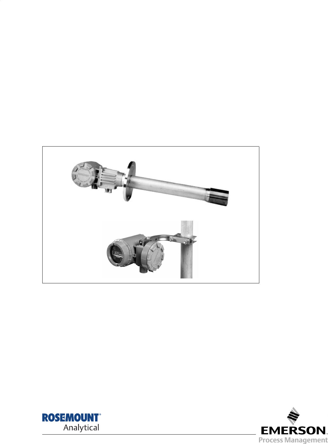
OXYMITTER 4000
HAZARDOUS AREA
OXYGEN TRANSMITTER
Emerson Process Management
Rosemount Analytical Inc.
Process Analytic Division
1201 N. Main St.
Orrville, OH 44667-0901
T (330) 682-9010
F (330) 684-4434
e-mail: gas.csc@EmersonProcess.com
http://www.processanalytic.com
ESSENTIAL INSTRUCTIONS
READ THIS PAGE BEFORE PROCEEDING!
Rosemount Analytical designs, manufactures and tests its products to meet many national and
international standards. Because these instruments are sophisticated technical products, you
MUST properly install, use, and maintain them to ensure they continue to operate within their
normal specifications. The following instructions MUST be adhered to and integrated into your
safety program when installing, using, and maintaining Rosemount Analytical products. Failure to
follow the proper instructions may cause any one of the following situations to occur: Loss of life;
personal injury; property damage; damage to this instrument; and warranty invalidation.
• Read all instructions prior to installing, operating, and servicing the product.
• If you do not understand any of the instructions, contact your Rosemount Analytical repre-
sentative for clarification.
• Follow all warnings, cautions, and instructions marked on and supplied with the product.
• Inform and educate your personnel in the proper installation, operation, and maintenance of
the product.
• Install your equipment as specified in the Installation Instructions of the appropriate Instruction
Manual and per applicable local and national codes. Connect all products to the proper elec-
trical and pressure sources.
• To ensure proper performance, use qualified personnel to install, operate, update, program,
and maintain the product.
• When replacement parts are required, ensure that qualified people use replacement parts
specified by Rosemount. Unauthorized parts and procedures can affect the product’s per-
formance, place the safe operation of your process at risk, and VOID YOUR WARRANTY.
Look-alike substitutions may result in fire, electrical hazards, or improper operation.
• Ensure that all equipment doors are closed and protective covers are in place, except when
maintenance is being performed by qualified persons, to prevent electrical shock and personal
injury.
The information contained in this document is subject to change without notice.
If a Model 275/375 Universal HART® Communicator is used with this unit, the software within
the Model 275/375 may require modification. If a software modification is required, please
contact your local Fisher-Rosemount Service Group or National Response Center at 1-800-
433-6076 or 1-888-433-6829.

HIGHLIGHTS OF CHANGES
Effective April, 2004 Rev. 4.0
Page Summary
Cover Updated revision number and date. Deleted certification data.
P-3 through P-14 Added foreign language versions of “Safety Instructions for the Wiring
and Installation of this Apparatus”.
1-1 Revised Warning. Revised para. 1-2a to include LOI and Model 375
communicator. All IB references to HART Model 275 changed to read
“HART Model 275/375”.
1-2 Revised Figure 1-1 to include Oxymitter 4000 remote electronics.
1-3 Revised para. 1-2c to include reference to remote electronics version.
1-4, 1-5 Revised para. 1-2d to include differences between units with LOI versus
membrane keypad and to include new Figure 1-3 and Figure 1-4 views.
1-6 Revised NOTE to define LOI operating temperature range data.
1-8 Added Figure 1-7 to show remote electronics versions.
1-12 Revised para. 1-7, Specifications to include LOI data, update electronic
noise data, temperature range data. Added pollution degree, over volt-
age category, and relative humidity data to specifications.
1-13 Added new paragraph 1-8, Hazardous Area Certifications.
1-14, 1-16 Revised Table 1-1, Product Matrix to update Communication Options
and Calibration Accessories, and to include Probe-to-Electronics Cables.
2-1 Revised para. 2-1a to reference remote electronics version and LOI.
Added temperature note.
2-3 Added new Figure 2-2; installation data for unit with remote electronics.
2-8 Added para. 2-1c and Figure 2-8 to discuss mounting of remote elec-
tronics version.
2-8 Revised para. 2-2 to apply to a unit with integral electronics only. Added
warning.
2-10 Added new Figure 2-9; wiring for unit with integral electronics.
2-11 Added new para. 2-3 to apply to a unit with remote electronics only.
2-12 Added new Figure 2-10, sheets 1 and 2, to identify different wiring views
as applicable to discrete system configurations.
2-15 Revised Figure 2-11 to list SI units first followed by U.S. standards.
Added note.
3-1 Revised Section 3 heading to apply to equipment configuration instruc-
tions for instruments with a membrane keypad.
3-2 Revised para. 3-1c to correct mA signal level values. Revise para. 3-1e
to define new voltage selection parameters.
3-3 Revised Figure 3-2 to update default parameter settings.

HIGHLIGHTS OF CHANGES (Continued)
Effective April, 2004 Rev. 4.0
Page Summary
3-5 Revised para. 3-3a to correct mA signal level values. Moved power up
and remaining procedures to Section 5, Startup and Operation.
4-1 through 4-5 Added new Section 4 to discuss system configuration instructions for
instruments with an LOI.
5-1 through 5-4 Added new Section 5 to cover equipment Startup and Operation for
instruments with a membrane keypad.
6-1 through 6-6 Added new Section 6 to cover equipment Startup and Operation for
instruments with an LOI.
8-1 Added new Figure 8-1 to show mV readings of an O2 sensor cell at nor-
mal operating temperature.
8-2 and 8-3 Revised para. 8-3 and 8-5 to include reference to LOI error indications.
8-4 Corrected mA signal level values in notes for Table 8-1. Added Table 8-2
to identify to LOI fault/alarm messages.
8-5 through 8-19 Revised Figure 8-3 through Figure 8-17 and related text to include LOI
fault/alarm messages and corrective actions.
8-20 Added new para. 8-6 to troubleshoot O2 cell faults that do not show an
alarm indication.
9-0 Moved calibration record sheet to front of section for easy access.
9-3 Added new procedural step, para. 9-2b.2(b) for use with LOI. Revised
heading of para. 9-2b.3 to Manual Calibration with Membrane Keypad.
9-7 through 9-20 Added new para. 9-4 heading to identify equipment repair procedures.
All component replacement procedures revised/reformatted accordingly.
9-8, 9-9 Revised Figure 9-3 to show LOI and glass window cover. Added new
Figure 9-4 to show remote electronics components.
9-12 Revised Figure 9-7.
11-1 through 11-4 Updated replacement parts lists.
Effective July, 2004 Rev. 4.1
Page Summary
Cover Updated revision number and date.
2-12 and 2-13 Added new Figure 2-10, sheets 1 and 2, to identify corrections to wiring
color codes.

Instruction Manual
IB-106-340C Rev. 4.1
July 2004
Rosemount Analytical Inc. A Division of Emerson Process Management i
Hazardous Area Oxymitter 4000
TABLE OF CONTENTS
PREFACE............................................................................................................................1
Definitions ............................................................................................................................1
Safety Instructions ...............................................................................................................2
1-0 DESCRIPTION AND SPECIFICATIONS........................................................................ 1-1
1-1 Component Checklist of Typical System (Package Contents)........................................ 1-1
1-2 System Overview............................................................................................................. 1-1
1-3 IMPS 4000 (Optional) ...................................................................................................... 1-9
1-4 SPS 4000 (Optional)........................................................................................................ 1-9
1-5 Model 751 Remote Powdered Loop LCD Display........................................................... 1-9
1-6 Probe Options................................................................................................................1-10
1-7 Specifications................................................................................................................. 1-12
1-8 Hazardous Area Certifications....................................................................................... 1-13
2-0 INSTALLATION .............................................................................................................. 2-1
2-1 Mechanical Installation .................................................................................................... 2-1
2-2 Electrical Installation
(for Hazardous Area Oxymitter 4000 with Integral Electronics) ...................................... 2-8
2-3 Electrical Installation
(for Hazardous Area Oxymitter 4000 with Remote Electronics)...................................... 2-9
2-4 Pneumatic Installation ................................................................................................... 2-14
2-5 IMPS 4000 Connections................................................................................................ 2-15
2-6 SPS 4000 Connections ................................................................................................. 2-15
3-0 CONFIGURATION OF HAZARDOUS AREA OXYMITTER 4000
WITH MEMBRANE KEYPAD ......................................................................................... 3-1
3-1 General ............................................................................................................................ 3-1
3-2 Logic I/O .......................................................................................................................... 3-4
3-3 Recommended Configuration.......................................................................................... 3-5
4-0 CONFIGURATION OF HAZARDOUS AREA OXYMITTER 4000 WITH LOI ................ 4-1
4-1 General ............................................................................................................................ 4-1
4-2 Logic I/O .......................................................................................................................... 4-4
4-3 Recommended Configuration.......................................................................................... 4-5
5-0 STARTUP AND OPERATION OF HAZARDOUS AREA OXYMITTER 4000
WITH MEMBRANE KEYPAD ......................................................................................... 5-1
5-1 Power Up ......................................................................................................................... 5-1
5-2 Operation ......................................................................................................................... 5-2

Instruction Manual
IB-106-340C Rev. 4.1
July 2004
ii Rosemount Analytical Inc. A Division of Emerson Process Management
Hazardous Area Oxymitter 4000
6-0 STARTUP AND OPERATION OF HAZARDOUS AREA OXYMITTER 4000
WITH LOI......................................................................................................................... 6-1
6-1 Power Up ......................................................................................................................... 6-1
6-2 Start Up Oxymitter 4000 Calibration................................................................................ 6-1
6-3 Navigating the Local Operator Interface.......................................................................... 6-2
6-4 LOI Key Designations ...................................................................................................... 6-2
6-5 LOI Menu Tree................................................................................................................. 6-3
6-6 Hazardous Area Oxymitter 4000 Setup at the LOI.......................................................... 6-4
6-7 LOI Installation................................................................................................................. 6-6
6-8 Oxymitter 4000 Test Points ............................................................................................. 6-7
6-9 Model 751 Remote Powered Loop LCD Display (Optional)............................................ 6-7
7-0 HART/AMS...................................................................................................................... 7-1
7-1 Overview.......................................................................................................................... 7-1
7-2 HART Communicator Signal Line Connections .............................................................. 7-1
7-3 HART Communicator PC Connections ........................................................................... 7-3
7-4 Off-Line and On-Line Operations .................................................................................... 7-3
7-5 Logic I/O Configurations .................................................................................................. 7-4
7-6 HART/AMS Menu Tree for Hazardous Area Oxymitter 4000 Applications ..................... 7-4
7-7 HART Communicator O2 CAL Method ............................................................................ 7-8
7-8 Defining a Timed Calibration via HART........................................................................... 7-9
8-0 TROUBLESHOOTING .................................................................................................... 8-1
8-1 Overview.......................................................................................................................... 8-1
8-2 General ............................................................................................................................ 8-2
8-3 Alarm Indications ............................................................................................................. 8-2
8-4 Alarm Contacts ................................................................................................................ 8-3
8-5 Identifying and Correcting Alarm Indications................................................................... 8-3
8-6 Hazardous Area Oxymitter 4000 Passes Calibration,
But Still Reads Incorrectly ............................................................................................. 8-20
9-0 MAINTENANCE AND SERVICE .................................................................................... 9-1
9-1 Overview.......................................................................................................................... 9-1
9-2 Calibration – Hazardous Area Oxymitter 4000 with Keypad ........................................... 9-1
9-3 Calibration – Hazardous Area Oxymitter 4000 with LOI.................................................. 9-5
9-4 Hazardous Area Oxymitter 4000 Repair ......................................................................... 9-7
10-0 RETURN OF MATERIAL .............................................................................................. 10-1
11-0 REPLACEMENT PARTS .............................................................................................. 11-1
12-0 OPTIONAL ACCESSORIES......................................................................................... 12-1
INDEX ....................................................................................................................................... 13-1

Instruction Manual
IB-106-340C Rev. 4.1
July 2004
Rosemount Analytical Inc. A Division of Emerson Process Management iii
Hazardous Area Oxymitter 4000
LIST OF ILLUSTRATIONS
Figure 1-1. Typical System Package ....................................................................................... 1-2
Figure 1-2. Hazardous Area Oxymitter 4000 Autocalibration System Options........................ 1-3
Figure 1-3. Membrane Keypad................................................................................................. 1-4
Figure 1-4. Local Operator Interface (LOI)............................................................................... 1-4
Figure 1-5. Hazardous Area Oxymitter 4000 HART Connections and AMS Application......... 1-6
Figure 1-6. Typical System Installation – Oxymitter 4000 with Integral Electronics ................ 1-7
Figure 1-7. Typical System Installation – Oxymitter 4000 with Remote Electronics................ 1-8
Figure 1-8. Model 751 Remote Powered Loop LCD Display .................................................. 1-9
Figure 1-9. Flame Arrestor Ceramic Diffusion Assembly........................................................ 1-10
Figure 1-10. Flame Arrestor Snubber Diffusion Assembly........................................................ 1-10
Figure 1-11. Abrasive Shield Assembly ................................................................................... 1-11
Figure 2-1. Hazardous Area Oxymitter 4000 Probe Installation .............................................. 2-2
Figure 2-2. Hazardous Area Oxymitter 4000 Remote Electronics Installation......................... 2-3
Figure 2-3. Hazardous Area Oxymitter 4000 Probe with Abrasive Shield ............................... 2-4
Figure 2-4. Hazardous Area Oxymitter 4000 Mounting Plate Dimensions .............................. 2-5
Figure 2-5. Hazardous Area Oxymitter 4000 Mounting Plate Installation................................ 2-6
Figure 2-6. Orienting the Optional Vee Deflector ..................................................................... 2-7
Figure 2-7. Installation with Drip Loop and Insulation Removal............................................... 2-8
Figure 2-8. Remote Electronics Mounting................................................................................ 2-8
Figure 2-9. Electrical Installation – Hazardous Area Oxymitter 4000
with Integral Electronics....................................................................................... 2-10
Figure 2-10. Electrical Installation – Hazardous Area Oxymitter 4000
with Remote Electronics ..................................................................................... 2-12
Figure 2-11. Air Set, Plant Air Connection ............................................................................... 2-15
Figure 2-12. Hazardous Area Oxymitter 4000 Gas Connections............................................ 2-15
Figure 3-1. Electronics Housing Terminals and Membrane Keypad........................................ 3-1
Figure 3-2. Defaults – Hazardous Area Oxymitter 4000 with Membrane Keypad ................... 3-3
Figure 4-1. Electronics Housing Terminals with LOI................................................................ 4-1
Figure 4-2. Defaults – Hazardous Area Oxymitter 4000 with LOI............................................ 4-3
Figure 5-1. Startup and Normal Operation............................................................................... 5-1
Figure 5-2. Calibration Keys..................................................................................................... 5-2
Figure 5-3. Normal Operation...................................................................................................5-3
Figure 6-1. Startup Display....................................................................................................... 6-1
Figure 6-2. Normal Display....................................................................................................... 6-1
Figure 6-3. LOI Features .......................................................................................................... 6-2
Figure 6-4. Local Operator Interface Menu Tree (Sheet 1 of 2)............................................... 6-3
Figure 6-5. LOI Module Connectors......................................................................................... 6-6
Figure 6-6. Test Points ............................................................................................................. 6-7
Figure 7-1. Signal Line Connections, ≥ 250 Ohms Load Resistance ...................................... 7-2
Figure 7-2. Signal Line Connections, < 250 Ohms Load Resistance ...................................... 7-3
Figure 7-3. HART/AMS Menu Tree (Sheet 1 of 3) ................................................................... 7-5
Figure 8-1. O2 Sensor mV Reading vs. % O2 at 736°C (Reference Air, 20.9% O2) ................ 8-1
Figure 8-2. Diagnostic LEDs ....................................................................................................8-2
Figure 8-3. Fault 1, Open Thermocouple ................................................................................. 8-5
Figure 8-4. Fault 2, Shorted Thermocouple ............................................................................. 8-6
Figure 8-5. Fault 3, Reversed Thermocouple .......................................................................... 8-7
Figure 8-6. Fault 4, A/D Comm Error ....................................................................................... 8-8
Figure 8-7. Fault 5, Open Heater ............................................................................................. 8-9
Figure 8-8. Fault 6, High High Heater Temp.......................................................................... 8-10
Figure 8-9. Fault 7, High Case Temp..................................................................................... 8-11

Instruction Manual
IB-106-340C Rev. 4.1
July 2004
iv Rosemount Analytical Inc. A Division of Emerson Process Management
Hazardous Area Oxymitter 4000
Figure 8-10. Fault 8, Low Heater Temp ................................................................................... 8-12
Figure 8-11. Fault 9, High Heater Temp .................................................................................. 8-13
Figure 8-12. Fault 10, High Cell mV......................................................................................... 8-14
Figure 8-13. Fault 11, Bad Cell ................................................................................................8-15
Figure 8-14. Fault 12, EEprom Corrupt.................................................................................... 8-16
Figure 8-15. Fault 13, Invalid Slope ......................................................................................... 8-17
Figure 8-16. Fault 14, Invalid Constant .................................................................................... 8-18
Figure 8-17. Fault 15, Last Calibration Failed .......................................................................... 8-19
Figure 8-18. Probe Leakage Paths .......................................................................................... 8-20
Figure 9-1. Membrane Keypad................................................................................................. 9-2
Figure 9-2. Inside Right Cover .................................................................................................9-4
Figure 9-3. Hazardous Area Oxymitter 4000 with Integral Electronics – Exploded View ........ 9-8
Figure 9-4. Hazardous Area Oxymitter 4000 with Remote Electronics – Exploded View........ 9-9
Figure 9-5. Electronic Assembly............................................................................................. 9-10
Figure 9-6. J8 Connector........................................................................................................ 9-11
Figure 9-7. Fuse Location ......................................................................................................9-12
Figure 9-8. Heater Strut Assembly......................................................................................... 9-14
Figure 9-9. Cell Replacement Kit ........................................................................................... 9-15
Figure 9-10. Ceramic Diffuser Element Replacement ............................................................. 9-16
Figure 9-11. Contact and Thermocouple Assembly Replacement .......................................... 9-18
Figure 11-1. Cell Replacement Kit ........................................................................................... 11-2
Figure 11-2. Probe Disassembly Kit......................................................................................... 11-3
LIST OF TABLES
Table 1-1. Product Matrix......................................................................................................1-14
Table 1-2. Calibration Components ...................................................................................... 1-16
Table 1-3. Intelligent Multiprobe Test Gas Sequencer Versions .......................................... 1-16
Table 3-1. Logic I/O Configuration (as set at HART/AMS or LOI) .......................................... 3-4
Table 4-1. Logic I/O Configuration (as set at HART/AMS or LOI) .......................................... 4-4
Table 7-1. Logic I/O Configuration (as set at HART/AMS or LOI) .......................................... 7-4
Table 8-1. Diagnostic/Unit Alarm Fault Definitions – Membrane Keypad Only ...................... 8-4
Table 8-2. Diagnostic/Unit Alarm Fault Definitions – LOI ....................................................... 8-4
Table 11-1. Replacement Parts for Probe .............................................................................. 11-1
Table 11-2. Replacement Parts for Electronics ...................................................................... 11-4
Instruction Manual
IB-106-340C Rev. 4.1
July 2004
Rosemount Analytical Inc. A Division of Emerson Process Management P-1
Hazardous Area Oxymitter 4000
PREFACE
The purpose of this manual is to provide information concerning the components, func-
tions, installation and maintenance of the Oxymitter 4000 Hazardous Area Oxygen
Transmitter.
Some sections may describe equipment not used in your configuration. The user should
become thoroughly familiar with the operation of this module before operating it. Read
this instruction manual completely.
DEFINITIONS
The following definitions apply to WARNINGS, CAUTIONS, and NOTES found throughout this
publication.
Highlights an operation or maintenance
procedure, practice, condition, state-
ment, etc. If not strictly observed, could
result in injury, death, or long-term
health hazards of personnel.
Highlights an operation or maintenance
procedure, practice, condition, state-
ment, etc. If not strictly observed, could
result in damage to or destruction of
equipment, or loss of effectiveness.
NOTE
Highlights an essential operating procedure,
condition, or statement.
: EARTH (GROUND) TERMINAL
: PROTECTIVE CONDUCTOR TERMINAL
: RISK OF ELECTRICAL SHOCK
: WARNING: REFER TO INSTRUCTION BULLETIN
NOTE TO USERS
The number in the lower right corner of each illustration in this publication is a manual illus-
tration number. It is not a part number, and is not related to the illustration in any technical
manner.
Instruction Manual
IB-106-340C Rev. 4.1
July 2004
P-2 Rosemount Analytical Inc. A Division of Emerson Process Management
Hazardous Area Oxymitter 4000
IMPORTANT
SAFETY INSTRUCTIONS
FOR THE WIRING AND INSTALLATION
OF THIS APPARATUS
The following safety instructions apply specifically to all EU member states. They should
be strictly adhered to in order to assure compliance with the Low Voltage Directive. Non-
EU states should also comply with the following unless superseded by local or National
Standards.
1. Adequate earth connections should be made to all earthing points, internal and external,
where provided.
2. After installation or troubleshooting, all safety covers and safety grounds must be re-
placed. The integrity of all earth terminals must be maintained at all times.
3. Mains supply cords should comply with the requirements of IEC227 or IEC245.
4. All wiring shall be suitable for use in an ambient temperature of greater than 75°C.
5. All cable glands used should be of such internal dimensions as to provide adequate cable
anchorage.
6. To ensure safe operation of this equipment, connection to the mains supply should only
be made through a circuit breaker which will disconnect all circuits carrying conductors
during a fault situation. The circuit breaker may also include a mechanically operated iso-
lating switch. If not, then another means of disconnecting the equipment from the supply
must be provided and clearly marked as such. Circuit breakers or switches must comply
with a recognized standard such as IEC947. All wiring must conform with any local stan-
dards.
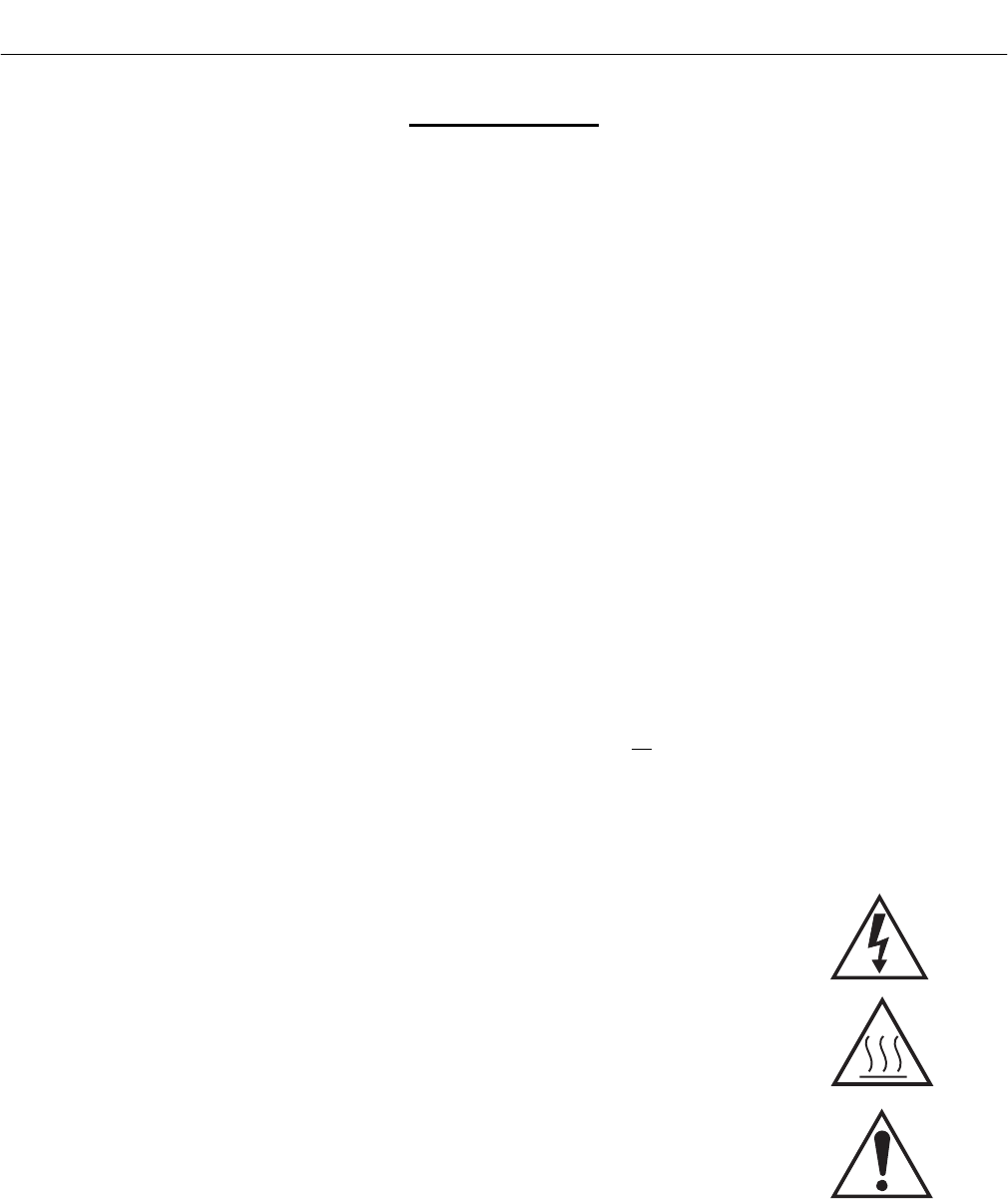
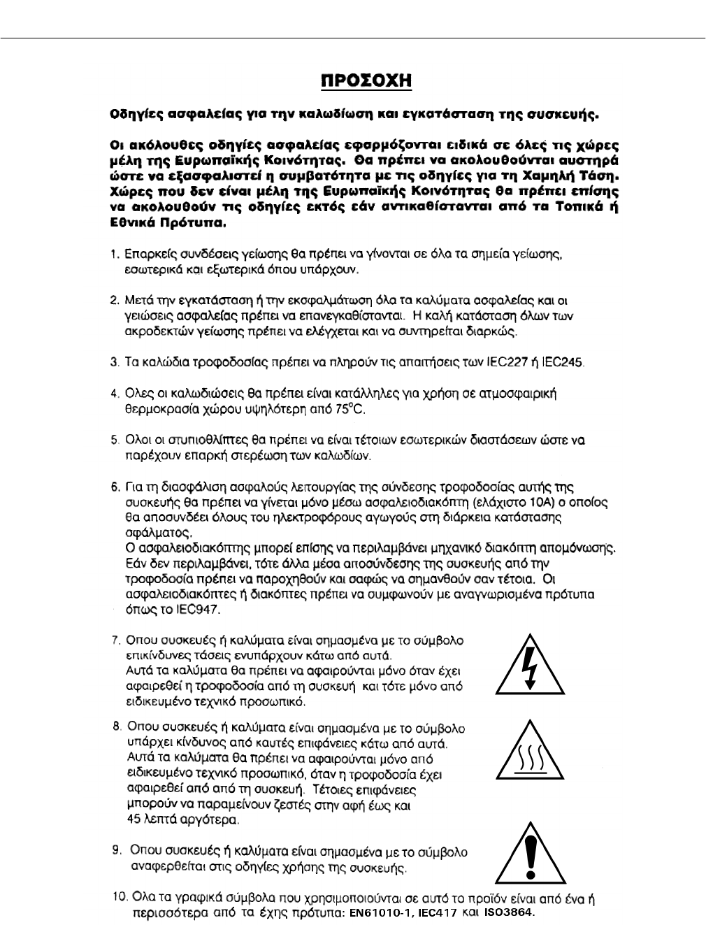
7. Where equipment or covers are marked with the symbol to the right, haz-
ardous voltages are likely to be present beneath. These covers should only
be removed when power is removed from the equipment — and then only
by trained service personnel.
8. Where equipment or covers are marked with the symbol to the right, there
is a danger from hot surfaces beneath. These covers should only be re-
moved by trained service personnel when power is removed from the
equipment. Certain surfaces may remain hot to the touch.
9. Where equipment or covers are marked with the symbol to the right, refer to
the Operator Manual for instructions.
10. All graphical symbols used in this product are from one or more of the fol-
lowing standards: EN61010-1, IEC417, and ISO3864.
Instruction Manual
IB-106-340C Rev. 4.1
July 2004
Rosemount Analytical Inc. A Division of Emerson Process Management P-3
Hazardous Area Oxymitter 4000
BELANGRIJK
Veiligheidsvoorschriften voor de aansluiting en installatie van dit toestel.
De hierna volgende veiligheidsvoorschriften zijn vooral bedoeld voor de EU lidstaten. Hier moet aan
gehouden worden om de onderworpenheid aan de Laag Spannings Richtlijn (Low Voltage Directive) te
verzekeren. Niet EU staten zouden deze richtlijnen moeten volgen tenzij zij reeds achterhaald zouden zijn
door plaatselijke of nationale voorschriften.
1. Degelijke aardingsaansluitingen moeten gemaakt worden naar alle voorziene aardpunten, intern en extern.
2. Na installatie of controle moeten alle veiligheidsdeksels en -aardingen terug geplaatst worden. Ten alle tijde
moet de betrouwbaarheid van de aarding behouden blijven.
3. Voedingskabels moeten onderworpen zijn aan de IEC227 of de IEC245 voorschriften.
4. Alle bekabeling moet geschikt zijn voor het gebruik in omgevingstemperaturen, hoger dan 75°C.
5. Alle wartels moeten zo gedimensioneerd zijn dat een degelijke kabel bevestiging verzekerd is.
6. Om de veilige werking van dit toestel te verzekeren, moet de voeding door een stroomonderbreker gevoerd
worden (min 10A) welke alle draden van de voeding moet onderbreken. De stroomonderbreker mag een
mechanische schakelaar bevatten. Zoniet moet een andere mogelijkheid bestaan om de voedingsspanning van
het toestel te halen en ook duidelijk zo zijn aangegeven. Stroomonderbrekers of schakelaars moeten
onderworpen zijn aan een erkende standaard zoals IEC947.
7. Waar toestellen of deksels aangegeven staan met het symbool is er meestal
hoogspanning aanwezig. Deze deksels mogen enkel verwijderd worden nadat
de voedingsspanning werd afgelegd en enkel door getraind
onderhoudspersoneel.
8. Waar toestellen of deksels aangegeven staan met het symbool is er gevaar
voor hete oppervlakken. Deze deksels mogen enkel verwijderd worden door
getraind onderhoudspersoneel nadat de voedingsspanning verwijderd werd.
Sommige oppper-vlakken kunnen 45 minuten later nog steeds heet aanvoelen.
9. Waar toestellen of deksels aangegeven staan met het symbool gelieve het
handboek te raadplegen.
10. Alle grafische symbolen gebruikt in dit produkt, zijn afkomstig uit een of meer van devolgende standaards:
EN61010-1, IEC417 en ISO3864.
Instruction Manual
IB-106-340C Rev. 4.1
July 2004
P-4 Rosemount Analytical Inc. A Division of Emerson Process Management
Hazardous Area Oxymitter 4000
VIGTIGT
Sikkerhedsinstruktion for tilslutning og installering af dette udstyr.
Følgende sikkerhedsinstruktioner gælder specifikt i alle EU-medlemslande. Instruktionerne skal nøje
følges for overholdelse af Lavsspændingsdirektivet og bør også følges i ikke EU-lande medmindre andet er
specificeret af lokale eller nationale standarder.
1. Passende jordforbindelser skal tilsluttes alle jordklemmer, interne og eksterne, hvor disse forefindes.
2. Efter installation eller fejlfinding skal alle sikkerhedsdæksler og jordforbindelser reetableres.
3. Forsyningskabler skal opfylde krav specificeret i IEC227 eller IEC245.
4. Alle ledningstilslutninger skal være konstrueret til omgivelsestemperatur højere end 75° C.
5. Alle benyttede kabelforskruninger skal have en intern dimension, så passende kabelaflastning kan etableres.
6. For opnåelse af sikker drift og betjening skal der skabes beskyttelse mod indirekte berøring gennem afbryder
(min. 10A), som vil afbryde alle kredsløb med elektriske ledere i fejlsitua-tion. Afbryderen skal indholde en
mekanisk betjent kontakt. Hvis ikke skal anden form for afbryder mellem forsyning og udstyr benyttes og
mærkes som sådan. Afbrydere eller kontakter skal overholde en kendt standard som IEC947.
7. Hvor udstyr eller dæksler er mærket med dette symbol, er farlige spændinger normalt
forekom-mende bagved. Disse dæksler bør kun afmonteres, når forsyningsspændingen er
frakoblet - og da kun af instrueret servicepersonale.
8. Hvor udstyr eller dæksler er mærket med dette symbol, forefindes meget varme overflader
bagved. Disse dæksler bør kun afmonteres af instrueret servicepersonale, når
forsyningsspænding er frakoblet. Visse overflader vil stadig være for varme at berøre i op
til 45 minutter efter frakobling.
9. Hvor udstyr eller dæksler er mærket med dette symbol, se da i betjeningsmanual for
instruktion.
10. Alle benyttede grafiske symboler i dette udstyr findes i én eller flere af følgende standarder:- EN61010-1,
IEC417 & ISO3864.
Instruction Manual
IB-106-340C Rev. 4.1
July 2004
Rosemount Analytical Inc. A Division of Emerson Process Management P-5
Hazardous Area Oxymitter 4000
BELANGRIJK
Veiligheidsinstructies voor de bedrading en installatie van dit apparaat.
Voor alle EU lidstaten zijn de volgende veiligheidsinstructies van toepassing. Om aan de geldende
richtlijnen voor laagspanning te voldoen dient men zich hieraan strikt te houden. Ook niet EU lidstaten
dienen zich aan het volgende te houden, tenzij de lokale wetgeving anders voorschrijft.
1. Alle voorziene interne- en externe aardaansluitingen dienen op adequate wijze aangesloten te worden.
2. Na installatie,onderhouds- of reparatie werkzaamheden dienen alle beschermdeksels /kappen en aardingen
om reden van veiligheid weer aangebracht te worden.
3. Voedingskabels dienen te voldoen aan de vereisten van de normen IEC 227 of IEC 245.
4. Alle bedrading dient geschikt te zijn voor gebruik bij een omgevings temperatuur boven 75°C.
5. Alle gebruikte kabelwartels dienen dusdanige inwendige afmetingen te hebben dat een adequate verankering
van de kabel wordt verkregen.
6. Om een veilige werking van de apparatuur te waarborgen dient de voeding uitsluitend plaats te vinden via
een meerpolige automatische zekering (min.10A) die alle spanningvoerende geleiders verbreekt indien een
foutconditie optreedt. Deze automatische zekering mag ook voorzien zijn van een mechanisch bediende
schakelaar. Bij het ontbreken van deze voorziening dient een andere als zodanig duidelijk aangegeven
mogelijkheid aanwezig te zijn om de spanning van de apparatuur af te schakelen. Zekeringen en schakelaars
dienen te voldoen aan een erkende standaard zoals IEC 947.
7. Waar de apparatuur of de beschermdeksels/kappen gemarkeerd zijn met het
volgende symbool, kunnen zich hieronder spanning voerende delen bevinden die
gevaar op kunnen leveren. Deze beschermdeksels/kappen mogen uitsluitend
verwijderd worden door getraind personeel als de spanning is afgeschakeld.
8. Waar de apparatuur of de beschermdeksels/kappen gemarkeerd zijn met het
volgende symbool, kunnen zich hieronder hete oppervlakken of onderdelen
bevinden. Bepaalde delen kunnen mogelijk na 45 min. nog te heet zijn om aan te
raken.
9. Waar de apparatuur of de beschermdeksels/kappen gemarkeerd zijn met het
volgende symbool, dient men de bedieningshandleiding te raadplegen.
10. Alle grafische symbolen gebruikt bij dit produkt zijn volgens een of meer van de volgende standaarden: EN
61010-1, IEC 417 & ISO 3864.
Instruction Manual
IB-106-340C Rev. 4.1
July 2004
P-6 Rosemount Analytical Inc. A Division of Emerson Process Management
Hazardous Area Oxymitter 4000
TÄRKEÄÄ
Turvallisuusohje, jota on noudatettava tämän laitteen asentamisessa ja kaapeloinnissa.
Seuraavat ohjeet pätevät erityisesti EU:n jäsenvaltioissa. Niitä täytyy ehdottomasti noudattaa jotta
täytettäisiin EU:n matalajännitedirektiivin (Low Voltage Directive) yhteensopivuus. Myös EU:hun
kuulumattomien valtioiden tulee nou-dattaa tätä ohjetta, elleivät kansalliset standardit estä sitä.
1. Riittävät maadoituskytkennät on tehtävä kaikkiin maadoituspisteisiin, sisäisiin ja ulkoisiin.
2. Asennuksen ja vianetsinnän jälkeen on kaikki suojat ja suojamaat asennettava takaisin pai-koilleen.
Maadoitusliittimen kunnollinen toiminta täytyy aina ylläpitää.
3. Jännitesyöttöjohtimien täytyy täyttää IEC227 ja IEC245 vaatimukset.
4. Kaikkien johdotuksien tulee toimia >75°C lämpötiloissa.
5. Kaikkien läpivientiholkkien sisähalkaisijan täytyy olla sellainen että kaapeli lukkiutuu kun-nolla kiinni.
6. Turvallisen toiminnan varmistamiseksi täytyy jännitesyöttö varustaa turvakytkimellä (min 10A), joka kytkee
irti kaikki jännitesyöttöjohtimet vikatilanteessa. Suojaan täytyy myös sisältyä mekaaninen erotuskytkin. Jos
ei, niin jännitesyöttö on pystyttävä katkaisemaan muilla keinoilla ja merkittävä siten että se tunnistetaan
sellaiseksi. Turvakytkimien tai kat-kaisimien täytyy täyttää IEC947 standardin vaatimukset näkyvyydestä.
7. Mikäli laite tai kosketussuoja on merkitty tällä merkillä on merkinnän takana tai alla
hengenvaarallisen suuruinen jännite. Suojaa ei saa poistaa jänniteen ollessa kytkettynä
laitteeseen ja poistamisen saa suorittaa vain alan asian-tuntija.
8. Mikäli laite tai kosketussuoja on merkitty tällä merkillä on merkinnän takana tai alla
kuuma pinta. Suojan saa poistaa vain alan asiantuntija kun jännite-syöttö on katkaistu.
Tällainen pinta voi säilyä kosketuskuumana jopa 45 mi-nuuttia.
9. Mikäli laite tai kosketussuoja on merkitty tällä merkillä katso lisäohjeita käyt-
töohjekirjasta
10. Kaikki tässä tuotteessa käytetyt graafiset symbolit ovat yhdestä tai useammasta seuraavis-ta standardeista:
EN61010-1, IEC417 & ISO3864.

Instruction Manual
IB-106-340C Rev. 4.1
July 2004
Rosemount Analytical Inc. A Division of Emerson Process Management P-7
Hazardous Area Oxymitter 4000
IMPORTANT
Consignes de sécurité concernant le raccordement et l’installation de cet appareil.
Les consignes de sécurité ci-dessous s’adressent particulièrement à tous les états membres de la
communauté européenne. Elles doivent être strictement appliquées afin de satisfaire aux directives
concernant la basse tension. Les états non membres de la communauté européenne doivent également
appliquer ces consignes sauf si elles sont en contradiction avec les standards locaux ou nationaux.
1. Un raccordement adéquat à la terre doit être effectuée à chaque borne de mise à la terre, interne et externe.
2. Après installation ou dépannage, tous les capots de protection et toutes les prises de terre doivent être remis
en place, toutes les prises de terre doivent être respectées en permanence.
3. Les câbles d’alimentation électrique doivent être conformes aux normes IEC227 ou IEC245
4. Tous les raccordements doivent pouvoir supporter une température ambiante supérieure à 75°C.
5. Tous les presse-étoupes utilisés doivent avoir un diamètre interne en rapport avec les câbles afin d’assurer un
serrage correct sur ces derniers.
6. Afin de garantir la sécurité du fonctionnement de cet appareil, le raccordement à l’alimentation électrique
doit être réalisé exclusivement au travers d’un disjoncteur (minimum 10A.) isolant tous les conducteurs en
cas d’anomalie. Ce disjoncteur doit également pouvoir être actionné manuellement, de façon mécanique.
Dans le cas contraire, un autre système doit être mis en place afin de pouvoir isoler l’appareil et doit être
signalisé comme tel. Disjoncteurs et interrupteurs doivent être conformes à une norme reconnue telle
IEC947.
7. Lorsque les équipements ou les capots affichent le symbole suivant, cela signifie
que des tensions dangereuses sont présentes. Ces capots ne doivent être démontés
que lorsque l’alimentation est coupée, et uniquement par un personnel compétent.
8. Lorsque les équipements ou les capots affichent le symbole suivant, cela signifie
que des surfaces dangereusement chaudes sont présentes. Ces capots ne doivent
être démontés que lorsque l’alimentation est coupée, et uniquement par un
personnel compétent. Certaines surfaces peuvent rester chaudes jusqu’à 45 mn.
9. Lorsque les équipements ou les capots affichent le symbole suivant, se reporter au
manuel d’instructions.
10. Tous les symboles graphiques utilisés dans ce produit sont conformes à un ou plusieurs des standards
suivants: EN61010-1, IEC417 & ISO3864.
Instruction Manual
IB-106-340C Rev. 4.1
July 2004
P-8 Rosemount Analytical Inc. A Division of Emerson Process Management
Hazardous Area Oxymitter 4000
Wichtig
Sicherheitshinweise für den Anschluß und die Installation dieser Geräte.
Die folgenden Sicherheitshinweise sind in allen Mitgliederstaaten der europäischen Gemeinschaft gültig.
Sie müssen strickt eingehalten werden, um der Niederspannungsrichtlinie zu genügen.
Nichtmitgliedsstaaten der europäischen Gemeinschaft sollten die national gültigen Normen und Richtlinien
einhalten.
1. Alle intern und extern vorgesehenen Erdungen der Geräte müssen ausgeführt werden.
2. Nach Installation, Reparatur oder sonstigen Eingriffen in das Gerät müssen alle Sicherheitsabdeckungen und
Erdungen wieder installiert werden. Die Funktion aller Erdverbindungen darf zu keinem Zeitpunkt gestört
sein.
3. Die Netzspannungsversorgung muß den Anforderungen der IEC227 oder IEC245 genügen.
4. Alle Verdrahtungen sollten mindestens bis 75 °C ihre Funktion dauerhaft erfüllen.
5. Alle Kabeldurchführungen und Kabelverschraubungen sollten in Ihrer Dimensionierung so gewählt werden,
daß diese eine sichere Verkabelung des Gerätes ermöglichen.
6. Um eine sichere Funktion des Gerätes zu gewährleisten, muß die Spannungsversorgung über mindestens 10
A abgesichert sein. Im Fehlerfall muß dadurch gewährleistet sein, daß die Spannungsversorgung zum Gerät
bzw. zu den Geräten unterbrochen wird. Ein mechanischer Schutzschalter kann in dieses System integriert
werden. Falls eine derartige Vorrichtung nicht vorhanden ist, muß eine andere Möglichkeit zur
Unterbrechung der Spannungszufuhr gewährleistet werden mit Hinweisen deutlich gekennzeichnet werden.
Ein solcher Mechanismus zur Spannungsunterbrechung muß mit den Normen und Richtlinien für die
allgemeine Installation von Elektrogeräten, wie zum Beispiel der IEC947, übereinstimmen.
7. Mit dem Symbol sind Geräte oder Abdeckungen gekennzeichnet, die eine gefährliche
(Netzspannung) Spannung führen. Die Abdeckungen dürfen nur entfernt werden,
wenn die Versorgungsspannung unterbrochen wurde. Nur geschultes Personal darf an
diesen Geräten Arbeiten ausführen.
8. Mit dem Symbol sind Geräte oder Abdeckungen gekennzeichnet, in bzw. unter denen
heiße Teile vorhanden sind. Die Abdeckungen dürfen nur entfernt werden, wenn die
Versorgungsspannung unterbrochen wurde. Nur geschultes Personal darf an diesen
Geräten Arbeiten ausführen. Bis 45 Minuten nach dem Unterbrechen der Netzzufuhr
können derartig Teile noch über eine erhöhte Temperatur verfügen.
9. Mit dem Symbol sind Geräte oder Abdeckungen gekennzeichnet, bei denen vor dem
Eingriff die entsprechenden Kapitel im Handbuch sorgfältig durchgelesen werden
müssen.
10. Alle in diesem Gerät verwendeten graphischen Symbole entspringen einem oder mehreren der nachfolgend
aufgeführten Standards: EN61010-1, IEC417 & ISO3864.
Instruction Manual
IB-106-340C Rev. 4.1
July 2004
Rosemount Analytical Inc. A Division of Emerson Process Management P-9
Hazardous Area Oxymitter 4000
IMPORTANTE
Norme di sicurezza per il cablaggio e l’installazione dello strumento.
Le seguenti norme di sicurezza si applicano specificatamente agli stati membri dell’Unione Europea, la cui
stretta osservanza è richiesta per garantire conformità alla Direttiva del Basso Voltaggio. Esse si applicano
anche agli stati non appartenenti all’Unione Europea, salvo quanto disposto dalle vigenti normative locali o
nazionali.
1. Collegamenti di terra idonei devono essere eseguiti per tutti i punti di messa a terra interni ed esterni, dove
previsti.
2. Dopo l’installazione o la localizzazione dei guasti, assicurarsi che tutti i coperchi di protezione siano stati
collocati e le messa a terra siano collegate. L’integrità di ciscun morsetto di terra deve essere costantemente
garantita.
3. I cavi di alimentazione della rete devono essere secondo disposizioni IEC227 o IEC245.
4. L’intero impianto elettrico deve essere adatto per uso in ambiente con temperature superiore a 75°C.
5. Le dimensioni di tutti i connettori dei cavi utilizzati devono essere tali da consentire un adeguato ancoraggio
al cavo.
6. Per garantire un sicuro funzionamento dello strumento il collegamento alla rete di alimentazione principale
dovrà essere eseguita tramite interruttore automatico (min.10A), in grado di disattivare tutti i conduttori di
circuito in caso di guasto. Tale interruttore dovrà inoltre prevedere un sezionatore manuale o altro dispositivo
di interruzione dell’alimentazione, chiaramente identificabile. Gli interruttori dovranno essere conformi agli
standard riconosciuti, quali IEC947.
7. Il simbolo riportato sullo strumento o sui coperchi di protezione indica probabile
presenza di elevati voltaggi. Tali coperchi di protezione devono essere rimossi
esclusivamente da personale qualificato, dopo aver tolto alimentazione allo
strumento.
8. Il simbolo riportato sullo strumento o sui coperchi di protezione indica rischio di
contatto con superfici ad alta temperatura. Tali coperchi di protezione devono
essere rimossi esclusivamente da personale qualificato, dopo aver tolto
alimentazione allo strumento. Alcune superfici possono mantenere temperature
elevate per oltre 45 minuti.
9. Se lo strumento o il coperchio di protezione riportano il simbolo, fare riferimento
alle istruzioni del manuale Operatore.
10. Tutti i simboli grafici utilizzati in questo prodotto sono previsti da uno o più dei seguenti standard: EN61010-
1, IEC417 e ISO3864.
Instruction Manual
IB-106-340C Rev. 4.1
July 2004
P-10 Rosemount Analytical Inc. A Division of Emerson Process Management
Hazardous Area Oxymitter 4000
VIKTIG
Sikkerhetsinstruks for tilkobling og installasjon av dette utstyret.
Følgende sikkerhetsinstruksjoner gjelder spesifikt alle EU medlemsland og land med i EØS-avtalen.
Instruksjonene skal følges nøye slik at installasjonen blir i henhold til lavspenningsdirektivet. Den bør også
følges i andre land, med mindre annet er spesifisert av lokale- eller nasjonale standarder.
1. Passende jordforbindelser må tilkobles alle jordingspunkter, interne og eksterne hvor disse forefinnes.
2. Etter installasjon eller feilsøking skal alle sikkerhetsdeksler og jordforbindelser reetableres.
Jordingsforbindelsene må alltid holdes i god stand.
3. Kabler fra spenningsforsyning skal oppfylle kravene spesifisert i IEC227 eller IEC245.
4. Alle ledningsforbindelser skal være konstruert for en omgivelsestemperatur høyere en 750C.
5. Alle kabelforskruvninger som benyttes skal ha en indre dimensjon slik at tilstrekkelig avlastning oppnåes.
6. For å oppnå sikker drift og betjening skal forbindelsen til spenningsforsyningen bare skje gjennom en
strømbryter (minimum 10A) som vil bryte spenningsforsyningen til alle elektriske kretser ved en
feilsituasjon. Strømbryteren kan også inneholde en mekanisk operert bryter for å isolere instrumentet fra
spenningsforsyningen. Dersom det ikke er en mekanisk operert bryter installert, må det være en annen måte å
isolere utstyret fra spenningsforsyningen, og denne måten må være tydelig merket. Kretsbrytere eller
kontakter skal oppfylle kravene i en annerkjent standard av typen IEC947 eller tilsvarende.
7. Der hvor utstyr eller deksler er merket med symbol for farlig spenning, er det sannsynlig at
disse er tilstede bak dekslet. Disse dekslene må bare fjærnes når spenningsforsyning er
frakoblet utstyret, og da bare av trenet servicepersonell.
8. Der hvor utstyr eller deksler er merket med symbol for meget varm overflate, er det
sannsynlig at disse er tilstede bak dekslet. Disse dekslene må bare fjærnes når
spenningsforsyning er frakoblet utstyret, og da bare av trenet servicepersonell. Noen
overflater kan være for varme til å berøres i opp til 45 minutter etter spenningsforsyning
frakoblet.
9. Der hvor utstyret eller deksler er merket med symbol, vennligst referer til
instruksjonsmanualen for instrukser.
10. Alle grafiske symboler brukt i dette produktet er fra en eller flere av følgende standarder: EN61010-1,
IEC417 & ISO3864.
Instruction Manual
IB-106-340C Rev. 4.1
July 2004
Rosemount Analytical Inc. A Division of Emerson Process Management P-11
Hazardous Area Oxymitter 4000
IMPORTANTE
Instruções de segurança para ligação e instalação deste aparelho.
As seguintes instruções de segurança aplicam-se especificamente a todos os estados membros da UE.
Devem ser observadas rigidamente por forma a garantir o cumprimento da Directiva sobre Baixa Tensão.
Relativamente aos estados que não pertençam à UE, deverão cumprir igualmente a referida directiva,
exceptuando os casos em que a legislação local a tiver substituído.
1. Devem ser feitas ligações de terra apropriadas a todos os pontos de terra, internos ou externos.
2. Após a instalação ou eventual reparação, devem ser recolocadas todas as tampas de segurança e terras de
protecção. Deve manter-se sempre a integridade de todos os terminais de terra.
3. Os cabos de alimentação eléctrica devem obedecer às exigências das normas IEC227 ou IEC245.
4. Os cabos e fios utilizados nas ligações eléctricas devem ser adequados para utilização a uma temperatura
ambiente até 75º C.
5. As dimensões internas dos bucins dos cabos devem ser adequadas a uma boa fixação dos cabos.
6. Para assegurar um funcionamento seguro deste equipamento, a ligação ao cabo de alimentação eléctrica deve
ser feita através de um disjuntor (min. 10A) que desligará todos os condutores de circuitos durante uma
avaria. O disjuntor poderá também conter um interruptor de isolamento accionado manualmente. Caso
contrário, deverá ser instalado qualquer outro meio para desligar o equipamento da energia eléctrica,
devendo ser assinalado convenientemente. Os disjuntores ou interruptores devem obedecer a uma norma
reconhecida, tipo IEC947.
7. Sempre que o equipamento ou as tampas contiverem o símbolo, é provável a
existência de tensões perigosas. Estas tampas só devem ser retiradas quando a
energia eléctrica tiver sido desligada e por Pessoal da Assistência devidamente
treinado.
8. Sempre que o equipamento ou as tampas contiverem o símbolo, há perigo de
existência de superfícies quentes. Estas tampas só devem ser retiradas por Pessoal
da Assistência devidamente treinado e depois de a energia eléctrica ter sido
desligada. Algumas superfícies permanecem quentes até 45 minutos depois.
9. Sempre que o equipamento ou as tampas contiverem o símbolo, o Manual de
Funcionamento deve ser consultado para obtenção das necessárias instruções.
10. Todos os símbolos gráficos utilizados neste produto baseiam-se em uma ou mais das seguintes normas:
EN61010-1, IEC417 e ISO3864.
Instruction Manual
IB-106-340C Rev. 4.1
July 2004
P-12 Rosemount Analytical Inc. A Division of Emerson Process Management
Hazardous Area Oxymitter 4000
IMPORTANTE
Instrucciones de seguridad para el montaje y cableado de este aparato.
Las siguientes instrucciones de seguridad , son de aplicacion especifica a todos los miembros de la UE y se
adjuntaran para cumplir la normativa europea de baja tension.
1. Se deben preveer conexiones a tierra del equipo, tanto externa como internamente, en aquellos terminales
previstos al efecto.
2. Una vez finalizada las operaciones de mantenimiento del equipo, se deben volver a colocar las cubiertas de
seguridad aasi como los terminales de tierra. Se debe comprobar la integridad de cada terminal.
3. Los cables de alimentacion electrica cumpliran con las normas IEC 227 o IEC 245.
4. Todo el cableado sera adecuado para una temperatura ambiental de 75ºC.
5. Todos los prensaestopas seran adecuados para una fijacion adecuada de los cables.
6. Para un manejo seguro del equipo, la alimentacion electrica se realizara a traves de un interruptor
magnetotermico ( min 10 A ), el cual desconectara la alimentacion electrica al equipo en todas sus fases
durante un fallo. Los interruptores estaran de acuerdo a la norma IEC 947 u otra de reconocido prestigio.
7. Cuando las tapas o el equipo lleve impreso el simbolo de tension electrica peligrosa,
dicho alojamiento solamente se abrira una vez que se haya interrumpido la
alimentacion electrica al equipo asimismo la intervencion sera llevada a cabo por
personal entrenado para estas labores.
8. Cuando las tapas o el equipo lleve impreso el simbolo, hay superficies con alta
temperatura, por tanto se abrira una vez que se haya interrumpido la alimentacion
electrica al equipo por personal entrenado para estas labores, y al menos se esperara
unos 45 minutos para enfriar las superficies calientes.
9. Cuando el equipo o la tapa lleve impreso el simbolo, se consultara el manual de
instrucciones.
10. Todos los simbolos graficos usados en esta hoja, estan de acuerdo a las siguientes normas EN61010-1,
IEC417 & ISO 3864.
Instruction Manual
IB-106-340C Rev. 4.1
July 2004
Rosemount Analytical Inc. A Division of Emerson Process Management P-13
Hazardous Area Oxymitter 4000
VIKTIGT
Säkerhetsföreskrifter för kablage och installation av denna apparat.
Följande säkerhetsföreskrifter är tillämpliga för samtliga EU-medlemsländer. De skall följas i varje
avseende för att överensstämma med Lågspännings direktivet. Icke EU medlemsländer skall också följa
nedanstående punkter, såvida de inte övergrips av lokala eller nationella föreskrifter.
1. Tillämplig jordkontakt skall utföras till alla jordade punkter, såväl internt som externt där så erfordras.
2. Efter installation eller felsökning skall samtliga säkerhetshöljen och säkerhetsjord återplaceras. Samtliga
jordterminaler måste hållas obrutna hela tiden.
3. Matningsspänningens kabel måste överensstämma med föreskrifterna i IEC227 eller IEC245.
4. Allt kablage skall vara lämpligt för användning i en omgivningstemperatur högre än 75ºC.
5. Alla kabelförskruvningar som används skall ha inre dimensioner som motsvarar adekvat kabelförankring.
6. För att säkerställa säker drift av denna utrustning skall anslutning till huvudströmmen endast göras genom en
säkring (min 10A) som skall frånkoppla alla strömförande kretsar när något fel uppstår. Säkringen kan även
ha en mekanisk frånskiljare. Om så inte är fallet, måste ett annat förfarande för att frånskilja utrustningen
från strömförsörjning tillhandahållas och klart framgå genom markering. Säkring eller omkopplare måste
överensstämma med en gällande standard såsom t ex IEC947.
7. Där utrustning eller hölje är markerad med vidstående symbol föreliggerisk för
livsfarlig spänning i närheten. Dessa höljen får endast avlägsnas när strömmen ej
är ansluten till utrustningen - och då endast av utbildad servicepersonal.
8. När utrustning eller hölje är markerad med vidstående symbol föreligger risk för
brännskada vid kontakt med uppvärmd yta. Dessa höljen får endast avlägsnas av
utbildad servicepersonal, när strömmen kopplats från utrustningen. Vissa ytor kan
vara mycket varma att vidröra även upp till 45 minuter efter avstängning av
strömmen.
9. När utrustning eller hölje markerats med vidstående symbol bör
instruktionsmanualen studeras för information.
10. Samtliga grafiska symboler som förekommer i denna produkt finns angivna i en eller flera av följande
föreskrifter:- EN61010-1, IEC417 & ISO3864.
Instruction Manual
IB-106-340C Rev. 4.1
July 2004
P-14 Rosemount Analytical Inc. A Division of Emerson Process Management
Hazardous Area Oxymitter 4000

Instruction Manual
IB-106-340C Rev. 4.1
July 2004
Rosemount Analytical Inc. A Division of Emerson Process Management P-15
Hazardous Area Oxymitter 4000
CERAMIC FIBER PRODUCTS
MATERIAL SAFETY DATA SHEET
JULY 1, 1996
SECTION I. IDENTIFICATION
PRODUCT NAME
Ceramic Fiber Heaters, Molded Insulation Modules and Ceramic Fiber Radiant Heater Panels.
CHEMICAL FAMILY
Vitreous Aluminosilicate Fibers with Silicon Dioxide.
CHEMICAL NAME
N.A.
CHEMICAL FORMULA
N.A.
MANUFACTURER’S NAME AND ADDRESS
Watlow Columbia 573-474-9402
2101 Pennsylvania Drive 573-814-1300, ext. 5170
Columbia, MO 65202
HEALTH HAZARD SUMMARY
WARNING
• Possible cancer hazard based on tests with laboratory animals.
• May be irritating to skin, eyes and respiratory tract.
• May be harmful if inhaled.
• Cristobalite (crystalline silica) formed at high temperatures (above 1800ºF) can cause severe respiratory
disease.

Instruction Manual
IB-106-340C Rev. 4.1
July 2004
P-16 Rosemount Analytical Inc. A Division of Emerson Process Management
Hazardous Area Oxymitter 4000
SECTION II. PHYSICAL DATA
APPEARANCE AND ODOR
Cream to white colored fiber shapes. With or without optional white to gray granular surface coating and/or
optional black surface coating.
SPECIFIC WEIGHT: 12-25 lb./cubic foot BOILING POINT: N.A.
VOLATILES (% BY WT.): N.A. WATER SOLUBILITY: N.A.
SECTION III. HAZARDOUS INGREDIENTS
MATERIAL, QUANTITY, AND THRESHOLD/EXPOSURE LIMIT VALUES
Aluminosilicate (vitreous) 99+ % 1 fiber/cc TWA
CAS. No. 142844-00-06 10 fibers/cc CL
Zirconium Silicate 0-10% 5 mg/cubic meter (TLV)
Black Surface Coating** 0 - 1% 5 mg/cubic meter (TLV)
Armorphous Silica/Silicon Dioxide 0-10% 20 mppcf (6 mg/cubic meter)
PEL (OSHA 1978) 3 gm cubic meter
(Respirable dust): 10 mg/cubic meter,
Intended TLV (ACGIH 1984-85)
**Composition is a trade secret.
SECTION IV. FIRE AND EXPLOSION DATA
FLASH POINT: None FLAMMABILITY LIMITS: N.A.
EXTINGUISHING MEDIA
Use extinguishing agent suitable for type of surrounding fire.
UNUSUAL FIRE AND EXPLOSION HAZARDS / SPECIAL FIRE FIGHTING PROCEDURES
N.A.

Instruction Manual
IB-106-340C Rev. 4.1
July 2004
Rosemount Analytical Inc. A Division of Emerson Process Management P-17
Hazardous Area Oxymitter 4000
SECTION V. HEALTH HAZARD DATA
THRESHOLD LIMIT VALUE
(See Section III)
EFFECTS OF OVER EXPOSURE
EYE
Avoid contact with eyes. Slightly to moderately irritating. Abrasive action may cause damage to outer surface
of eye.
INHALATION
May cause respiratory tract irritation. Repeated or prolonged breathing of particles of respirable size may cause
inflammation of the lung leading to chest pain, difficult breathing, coughing and possible fibrotic change in the
lung (Pneumoconiosis). Pre-existing medical conditions may be aggravated by exposure: specifically, bron-
chial hyper-reactivity and chronic bronchial or lung disease.
INGESTION
May cause gastrointestinal disturbances. Symptoms may include irritation and nausea, vomiting and diarrhea.
SKIN
Slightly to moderate irritating. May cause irritation and inflammation due to mechanical reaction to sharp, bro-
ken ends of fibers.
EXPOSURE TO USED CERAMIC FIBER PRODUCT
Product which has been in service at elevated temperatures (greater than 1800ºF/982ºC) may undergo partial
conversion to cristobalite, a form of crystalline silica which can cause severe respiratory disease (Pneumoco-
niosis). The amount of cristobalite present will depend on the temperature and length of time in service. (See
Section IX for permissible exposure levels).
SPECIAL TOXIC EFFECTS
The existing toxicology and epidemiology data bases for RCF’s are still preliminary. Information will be up-
dated as studies are completed and reviewed. The following is a review of the results to date:
EPIDEMIOLOGY
At this time there are no known published reports demonstrating negative health outcomes of workers exposed
to refractory ceramic fiber (RCF). Epidemiologic investigations of RCF production workers are ongoing.
1) There is no evidence of any fibrotic lung disease (interstitial fibrosis) whatsoever on x-ray.
2) There is no evidence of any lung disease among those employees exposed to RCF that had never smoked.
3) A statistical “trend” was observed in the exposed population between the duration of exposure to RCF and a
decrease in some measures of pulmonary function. These observations are clinically insignificant. In other words, if
these observations were made on an individual employee, the results would be interpreted as being within the
normal range.
4) Pleural plaques (thickening along the chest wall) have been observed in a small number of employees who had a
long duration of employment. There are several occupational and non-occupational causes for pleural plaque. It
should be noted that plaques are not “pre-cancer” nor are they associated with any measurable effect on lung
function.

Instruction Manual
IB-106-340C Rev. 4.1
July 2004
P-18 Rosemount Analytical Inc. A Division of Emerson Process Management
Hazardous Area Oxymitter 4000
TOXICOLOGY
A number of studies on the health effects of inhalation exposure of rats and hamsters are available. Rats were
exposed to RCF in a series of life-time nose-only inhalation studies. The animals were exposed to 30, 16, 9,
and 3 mg/m3, which corresponds with approximately 200, 150, 75, and 25 fibers/cc.
Animals exposed to 30 and 16 mg/m3 were observed to have developed a pleural and parenchymal fibroses;
animals exposed to 9 mg/m3 had developed a mild parenchymal fibrosis; animals exposed to the lowest dose
were found to have the response typically observed any time a material is inhaled into the deep lung. While a
statistically significant increase in lung tumors was observed following exposure to the highest dose, there was
no excess lung cancers at the other doses. Two rats exposed to 30 mg/m3 and one rat exposed to 9 mg/m3 de-
veloped masotheliomas.
The International Agency for Research on Cancer (IARC) reviewed the carcinogenicity data on man-made vit-
reous fibers (including ceramic fiber, glasswool, rockwool, and slagwool) in 1987. IARC classified ceramic fi-
ber, fibrous glasswool and mineral wool (rockwool and slagwool) as possible human carcinogens (Group 2B).
EMERGENCY FIRST AID PROCEDURES
EYE CONTACT
Flush eyes immediately with large amounts of water for approximately 15 minutes. Eye lids should be held
away from the eyeball to insure thorough rinsing. Do not rub eyes. Get medical attention if irritation persists.
INHALATION
Remove person from source of exposure and move to fresh air. Some people may be sensitive to fiber induced
irritation of the respiratory tract. If symptoms such as shortness of breath, coughing, wheezing or chest pain
develop, seek medical attention. If person experiences continued breathing difficulties, administer oxygen until
medical assistance can be rendered.
INGESTION
Do not induce vomiting. Get medical attention if irritation persists.
SKIN CONTACT
Do not rub or scratch exposed skin. Wash area of contact thoroughly with soap and water. Using a skin cream
or lotion after washing may be helpful. Get medical attention if irritation persists.
SECTION VI. REACTIVITY DATA
STABILITY/CONDITIONS TO AVOID
Stable under normal conditions of use.
HAZARDOUS POLYMERIZATION/CONDITIONS TO AVOID
N.A.
INCOMPATIBILITY/MATERIALS TO AVOID
Incompatible with hydrofluoric acid and concentrated alkali.
HAZARDOUS DECOMPOSITION PRODUCTS
N.A.

Instruction Manual
IB-106-340C Rev. 4.1
July 2004
Rosemount Analytical Inc. A Division of Emerson Process Management P-19
Hazardous Area Oxymitter 4000
SECTION VII. SPILL OR LEAK PROCEDURES
STEPS TO BE TAKEN IF MATERIAL IS RELEASED OR SPILLED
Where possible, use vacuum suction with HEPA filters to clean up spilled material. Use dust suppressant
where sweeping if necessary. Avoid clean up procedure which may result in water pollution. (Observe Special
Protection Information Section VIII.)
WASTE DISPOSAL METHODS
The transportation, treatment, and disposal of this waste material must be conducted in compliance with all ap-
plicable Federal, State, and Local regulations.
SECTION VIII. SPECIAL PROTECTION INFORMATION
RESPIRATORY PROTECTION
Use NIOSH or MSHA approved equipment when airborne exposure limits may be exceeded. NIOSH/MSHA
approved breathing equipment may be required for non-routine and emergency use. (See Section IX for suit-
able equipment).
Pending the results of long term health effects studies, engineering control of airborne fibers to the lowest lev-
els attainable is advised.
VENTILATION
Ventilation should be used whenever possible to control or reduce airborne concentrations of fiber and dust.
Carbon monoxide, carbon dioxide, oxides of nitrogen, reactive hydrocarbons and a small amount of formalde-
hyde may accompany binder burn-off during first heat. Use adequate ventilation or other precautions to elimi-
nate vapors resulting from binder burn-off. Exposure to burn-off fumes may cause respiratory tract irritation,
bronchial hyper-reactivity and asthmatic response.
SKIN PROTECTION
Wear gloves, hats and full body clothing to prevent skin contact. Use separate lockers for work clothes to pre-
vent fiber transfer to street clothes. Wash work clothes separately from other clothing and rinse washing ma-
chine thoroughly after use.
EYE PROTECTION
Wear safety glasses or chemical worker’s goggles to prevent eye contact. Do not wear contact lenses when
working with this substance. Have eye baths readily available where eye contact can occur.

Instruction Manual
IB-106-340C Rev. 4.1
July 2004
P-20 Rosemount Analytical Inc. A Division of Emerson Process Management
Hazardous Area Oxymitter 4000
SECTION IX. SPECIAL PRECAUTIONS
PRECAUTIONS TO BE TAKEN IN HANDLING AND STORING
General cleanliness should be followed.
The Toxicology data indicate that ceramic fiber should be handled with caution. The handling practices de-
scribed in this MSDS must be strictly followed. In particular, when handling refractory ceramic fiber in any
application, special caution should be taken to avoid unnecessary cutting and tearing of the material to mini-
mize generation of airborne dust.
It is recommended that full body clothing be worn to reduce the potential for skin irritation. Washable or dis-
posable clothing may be used. Do not take unwashed work clothing home. Work clothes should be washed
separately from other clothing. Rinse washing machine thoroughly after use. If clothing is to be laundered by
someone else, inform launderer of proper procedure. Work clothes and street clothes should be kept separate to
prevent contamination.
Product which has been in service at elevated temperatures (greater than 1800ºF/982ºC) may undergo partial
conversion to cristobalite, a form of crystalline silica. This reaction occurs at the furnace lining hot face. As a
consequence, this material becomes more friable; special caution must be taken to minimize generation of air-
borne dust. The amount of cristobalite present will depend on the temperature and length in service.
IARC has recently reviewed the animal, human, and other relevant experimental data on silica in order to criti-
cally evaluate and classify the cancer causing potential. Based on its review, IARC classified crystalline silica
as a group 2A carcinogen (probable human carcinogen).
The OSHA permissible exposure limit (PEL for cristobalite is 0.05 mg/m3 (respirable dust). The ACGIH
threshold limit value (TLV) for cristobalite is 0.05 mg/m3 (respirable dust) (ACGIH 1991-92). Use NIOSH or
MSHA approved equipment when airborne exposure limits may be exceeded. The minimum respiratory pro-
tection recommended for given airborne fiber or cristobalite concentrations are:
CONCENTRATION
0-1 fiber/cc or 0-0.05 mg/m3 cristobalite Optional disposable dust respirator (e.g. 3M
(the OSHA PEL) 9970 or equivalent).
Up to 5 fibers/cc or up to 10 times the Half face, air-purifying respirator equipped
OSHA PEL for cristobalite with high efficiency particulate air (HEPA)
filter cartridges (e.g. 3M 6000 series with
2040 filter or equivalent).
Up to 25 fibers/cc or 50 times the OSHA Full face, air-purifying respirator with high
PEL for cristobalite (2.5 mg/m3) efficiency particulate air (HEPA) filter cart-
ridges (e.g. 3M 7800S with 7255 filters or
equivalent) or powered air-purifying respirator
(PARR) equipped with HEPA filter cartridges
(e.g. 3M W3265S with W3267 filters or
equivalent).
Greater than 25 fibers/cc or 50 times the Full face, positive pressure supplied air respira-
OSHA PEL for cristobalite (2.5 mg/m3) tor (e.g. 3M 7800S with W9435 hose & W3196
low pressure regulator kit connected to clean
air supply or equivalent).
If airborne fiber or cristobalite concentrations are not known, as minimum protection, use NIOSH/MSHA approved
half face, air-purifying respirator with HEPA filter cartridges.

Instruction Manual
IB-106-340C Rev. 4.1
July 2004
Rosemount Analytical Inc. A Division of Emerson Process Management P-21
Hazardous Area Oxymitter 4000
Insulation surface should be lightly sprayed with water before removal to suppress airborne dust. As water evapo-
rates during removal, additional water should be sprayed on surfaces as needed. Only enough water should be
sprayed to suppress dust so that water does not run onto the floor of the work area. To aid the wetting process, a sur-
factant can be used.
After RCF removal is completed, dust-suppressing cleaning methods, such as wet sweeping or vacuuming, should
be used to clean the work area. If dry vacuuming is used, the vacuum must be equipped with HEPA filter. Air
blowing or dry sweeping should not be used. Dust-suppressing components can be used to clean up light dust.
Product packaging may contain product residue. Do not reuse except to reship or return Ceramic Fiber products to
the factory.

Instruction Manual
IB-106-340C Rev. 4.1
July 2004
P-22 Rosemount Analytical Inc. A Division of Emerson Process Management
Hazardous Area Oxymitter 4000
GENERAL PRECAUTIONS FOR HANDLING AND
STORING HIGH PRESSURE GAS CYLINDERS
Edited from selected paragraphs of the Compressed
Gas Association’s “Handbook of Compressed Gases”
published in 1981
Compressed Gas Association
1235 Jefferson Davis Highway
Arlington, Virginia 22202
Used by Permission
1. Never drop cylinders or permit them to strike each other violently.
2. Cylinders may be stored in the open, but in such cases, should be protected against extremes of weather and, to prevent
rusting, from the dampness of the ground. Cylinders should be stored in the shade when located in areas where extreme
temperatures are prevalent.
3. The valve protection cap should be left on each cylinder until it has been secured against a wall or bench, or placed in a
cylinder stand, and is ready to be used.
4. Avoid dragging, rolling, or sliding cylinders, even for short distance; they should be moved by using a suitable hand-
truck.
5. Never tamper with safety devices in valves or cylinders.
6. Do not store full and empty cylinders together. Serious suckback can occur when an empty cylinder is attached to a pres-
surized system.
7. No part of cylinder should be subjected to a temperature higher than 52°C (125°F). A flame should never be permitted to
come in contact with any part of a compressed gas cylinder.
8. Do not place cylinders where they may become part of an electric circuit. When electric arc welding, precautions must
be taken to prevent striking an arc against the cylinder.

Instruction Manual
IB-106-340C Rev. 4.1
July 2004
Rosemount Analytical Inc. A Division of Emerson Process Management Description and Specifications 1-1
Hazardous Area Oxymitter 4000
SECTION 1
DESCRIPTION AND SPECIFICATIONS
1-1 COMPONENT CHECKLIST OF TYPICAL
SYSTEM (PACKAGE CONTENTS)
A typical Rosemount Hazardous Area Oxymitter
4000 Oxygen Transmitter should contain the
items shown in Figure 1-1. Record the part
number, serial number, and order number for
each component of your system in the table
located on the first page of this manual.
The Oxymitter 4000 is offered in both
hazardous area and general purpose
configurations. The hazardous area
version has special markings on the
approval label. The general purpose
version does not. If you received the
general purpose version, ensure you
do not install it in a potentially explo-
sive atmosphere.
Also, use the product matrix in Table 1-1 at the
end of this section to compare your order num-
ber against your unit. The first part of the matrix
defines the model. The last part defines the
various options and features of the Hazardous
Area Oxymitter 4000. Ensure the features and
options specified by your order number are on
or included with the unit.
1-2 SYSTEM OVERVIEW
a. Scope
This Instruction Bulletin provides the infor-
mation needed to install, start up, operate,
and maintain the Hazardous Area Oxymitter
4000. Signal conditioning electronics out-
puts a 4-20 mA signal representing an O2
value and provides a membrane keypad or
full function Local Operator Interface (LOI)
for setup, calibration, and diagnostics. This
same information, plus additional details,
can be accessed with the
HART Model 275/375 handheld communi-
cator or Asset Management Solutions
(AMS) software.
b. System Description
The Hazardous Area Oxymitter 4000 is
designed to measure the net concentration
of oxygen in an industrial process; i.e., the
oxygen remaining after all fuels have been
oxidized. The probe is permanently posi-
tioned within an exhaust duct or stack and
performs its task without the use of a
sampling system.
The equipment measures oxygen percent-
age by reading the voltage developed
across a heated electrochemical cell, which
consists of a small yttria-stabilized, zirconia
disc. Both sides of the disc are coated with
porous metal electrodes. When operated at
the proper temperature, the millivolt output
voltage of the cell is given by the following
Nernst equation:
EMF = KT log10(P1/P2) + C
Where:
1. P2 is the partial pressure of the oxy-
gen in the measured gas on one side
of the cell.
2. P1 is the partial pressure of the oxy-
gen in the reference air on the oppo-
site side of the cell.
3. T is the absolute temperature.
4. C is the cell constant.
5. K is an arithmetic constant.
NOTE
For best results, use clean, dry, instru-
ment air (20.95% oxygen) as the refer-
ence air.
1
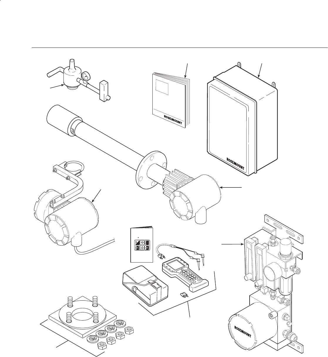
Instruction Manual
IB-106-340C Rev. 4.1
July 2004
1-2 Description and Specifications Rosemount Analytical Inc. A Division of Emerson Process Management
Hazardous Area Oxymitter 4000
2
8
1
4
3
37270007
6
7
o
HART Communicator
FISHER-ROSEMOUNT
TM
MAN 4275A00
English
October 1994
5
1. Instruction Bulletin
2. IMPS 4000 Intelligent Multiprobe Test Gas Sequencer (Optional)
3. Hazardous Area Oxymitter 4000 with Integral Electronics
4. SPS 4000 Single Probe Autocalibration Sequencer (Optional) - (Shown with reference air option) (Safe area only)
5. HART® Communicator Package, Model 375 (Optional)
6. Mounting Plate with Mounting Hardware and Gasket
7. Hazardous Area Oxymitter 4000 with Remote Electronics (Optional)
8. Reference Air Set (used if SPS 4000 without reference air option or IMPS 4000 not supplied)
Figure 1-1. Typical System Package
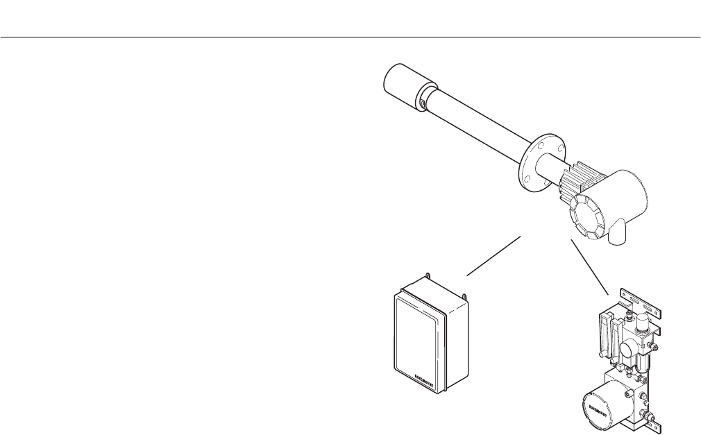
Instruction Manual
IB-106-340C Rev. 4.1
July 2004
Rosemount Analytical Inc. A Division of Emerson Process Management Description and Specifications 1-3
Hazardous Area Oxymitter 4000
When the cell is at operating temperature
and there are unequal oxygen concentra-
tions across the cell, oxygen ions will travel
from the high oxygen partial pressure side
to the low oxygen partial pressure side of
the cell. The resulting logarithmic output
voltage is approximately 50 mV per decade.
The output is proportional to the inverse
logarithm of the oxygen concentration.
Therefore, the output signal increases as
the oxygen concentration of the sample gas
decreases. This characteristic enables the
Hazardous Area Oxymitter 4000 to provide
exceptional sensitivity at low oxygen
concentrations.
The Hazardous Area Oxymitter 4000 meas-
ures net oxygen concentration in the pres-
ence of all the products of combustion,
including water vapor. Therefore, it may be
considered an analysis on a “wet” basis. In
comparison with older methods, such as the
portable apparatus, which provides an
analysis on a “dry” gas basis, the “wet”
analysis will, in general, indicate a lower
percentage of oxygen. The difference will
be proportional to the water content of the
sampled gas stream.
c. System Configuration
Hazardous Area Oxymitter 4000 units are
available in three length options, giving the
user the flexibility to use an in situ penetra-
tion appropriate to the size of the stack or
duct. The options on length are 457 mm
(18 in.), 0.91 m (3 ft), and 1.83 m (6 ft).
The electronics control probe temperatures
and provide an isolated output, 4-20 mA,
that is proportional to the measured oxygen
concentration. The power supply can accept
voltages of 90-250 VAC and 48/62 Hz; no
setup procedures are required. The oxygen
sensing cell is maintained at a constant
temperature by modulating the duty cycle of
the probe heater portion of the electronics.
The electronics accepts millivolt signals
generated by the sensing cell and produces
the outputs to be used by remotely con-
nected devices. The output is an isolated
4-20 mA linearized current.
HAZARDOUS AREA
OXYMITTER 4000
IMPS 4000
(1 TO 4 PROBES)
(MUST BE INSTALLED
IN A SAFE AREA
OR BE X- OR Z-PURGED
BY THE CUSTOMER)
REMOTE MOUNTED
SPS 4000
(1 PROBE)
(MUST BE INSTALLED
IN A SAFE AREA)
26310002
Figure 1-2. Hazardous Area Oxymitter 4000
Autocalibration System Options
The Oxymitter 4000 transmitter is available
with an integral or remote electronics pack-
age. Two calibration gas sequencers are
available to the Hazardous Area Oxymitter
4000, but they must be installed in a non-
hazardous, explosive-free environment: the
IMPS 4000 and the SPS 4000 (Figure 1-2).
Systems with multiprobe applications may
employ an optional IMPS 4000 Intelligent
Multiprobe Test Gas Sequencer. The IMPS
4000 provides automatic calibration gas
sequencing for up to four Hazardous Area
Oxymitter 4000 units and accommodates
autocalibrations based on the CALIBRA-
TION RECOMMENDED signal from the
Hazardous Area Oxymitter 4000, a timed
interval set up in HART or the IMPS 4000,
or whenever a calibration request is
initiated.
1
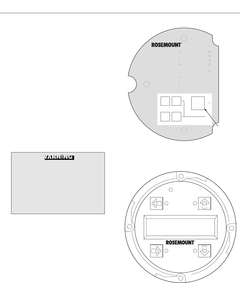
Instruction Manual
IB-106-340C Rev. 4.1
July 2004
1-4 Description and Specifications Rosemount Analytical Inc. A Division of Emerson Process Management
Hazardous Area Oxymitter 4000
For systems with one or two Hazardous
Area Oxymitter 4000 units per combustion
process, an optional remote mounted SPS
4000 Single Probe Autocalibration
Sequencer can be used with each Hazard-
ous Area Oxymitter 4000 to provide auto-
matic calibration gas sequencing. The
sequencer performs autocalibrations based
on the CALIBRATION RECOMMENDED
signal from the Hazardous Area Oxymitter
4000, a timed interval set up in HART, or
whenever a calibration request is initiated.
d. System Features
1. The CALIBRATION RECOMMENDED
feature detects when the sensing cell
is likely out of limits. This may eliminate
the need to calibrate on a “time since
last cal” basis.
2. The cell output voltage and sensitivity
increase as the oxygen concentration
decreases.
The HART option is not protected by
energy limiting barriers. It must not be
interfaced from within the hazardous
area. The 4-20 mA cables should be
routed and the connections made out-
side the hazardous area. Note that this
is the case even when using the in-
trinsically safe version of the handheld
communicator.
3. Membrane keypad Figure 1-3 and
HART communication are standard.
To use the HART capability, you must
have either:
(a) HART Model 275/375 Communi-
cator.
(b) Asset Management Solutions
(AMS) software for the PC.
4. An optional Local Operator Interface
Figure 1-4 allows continual O2 display
and full interface capability.
DIAGNOSTIC
ALARMS
TEST
POINTS
HEATER T/C
HEATER
02 CELL
CALIBRATION
CALIBRATION RECOMMENDED
02 CELL mV +
02 CELL mv -
HEATER T/C +
HEATER T/C -
INC INC
DEC DEC
HIGH
GAS
LOW
GAS
CAL
TEST GAS +
PROCESS -
% 02
MEMBRANE
KEYPAD
37260003
Figure 1-3. Membrane Keypad
37260004
Figure 1-4. Local Operator Interface (LOI)

Instruction Manual
IB-106-340C Rev. 4.1
July 2004
Rosemount Analytical Inc. A Division of Emerson Process Management Description and Specifications 1-5
Hazardous Area Oxymitter 4000
5. Field replaceable cell, heater, thermo-
couple, diffuser, and PC boards.
6. The Hazardous Area Oxymitter 4000 is
constructed of rugged 316L stainless
steel for all wetted parts.
7. The electronics is adaptable for line
voltages from 90-250 VAC; therefore,
no configuration is necessary.
8. The Hazardous Area Oxymitter 4000
membrane keypad is available in five
languages: English, French, German,
Italian, and Spanish.
9. An operator can calibrate and com-
municate with the Hazardous Area
Oxymitter 4000 in one of three ways:
Accessing the probe keypad requires
opening the electronics housing.
Opening the electronic housing will
cause the loss of ALL hazardous per-
mits. Opening the electronics housing
in hazardous areas may cause an ex-
plosion resulting in loss of property,
severe personal injury, or death. It
may be required to get a hot work
permit from your company safety offi-
cer before opening the electronic
housing.
(a) Membrane Keypad. The mem-
brane keypad, housed within the
right side of the electronics hous-
ing, provides fault indication by
way of flashing LEDs. Calibration
can be performed from the mem-
brane keypad.
(b) LOI. The optional LOI takes the
place of the membrane keypad
and allows local communication
with the electronics. Refer to Sec-
tion 4 for more information.
The HART option is not protected by
energy limiting barriers. It must not be
interfaced from within the hazardous
area. The 4-20 mA cables should be
routed and the connections made out-
side the hazardous area. Note that this
is the case even when using the in-
trinsically safe version of the handheld
communicator.
(c) Optional HART Interface. The
Hazardous Area Oxymitter 4000’s
4-20 mA output line transmits an
analog signal proportional to the
oxygen level. The HART output is
superimposed on the 4-20 mA out-
put signal. This information can be
accessed through the following:
1 Rosemount Model 275/375
Handheld Communicator -
The handheld communicator
requires Device Description
(DD) software specific to the
Hazardous Area Oxymitter
4000. The DD software will be
supplied with many Model
275/375 units but can also be
programmed into existing
units at most Fisher-
Rosemount service offices.
See Section 7, HART/AMS,
for additional information.
2 Personal Computer (PC) -
The use of a personal com-
puter requires AMS software
available from Fisher
Rosemount.
3 Selected Distributed Control
Systems - The use of distrib-
uted control systems requires
input/output (I/O) hardware
and AMS software which
permit HART communica-
tions.
1
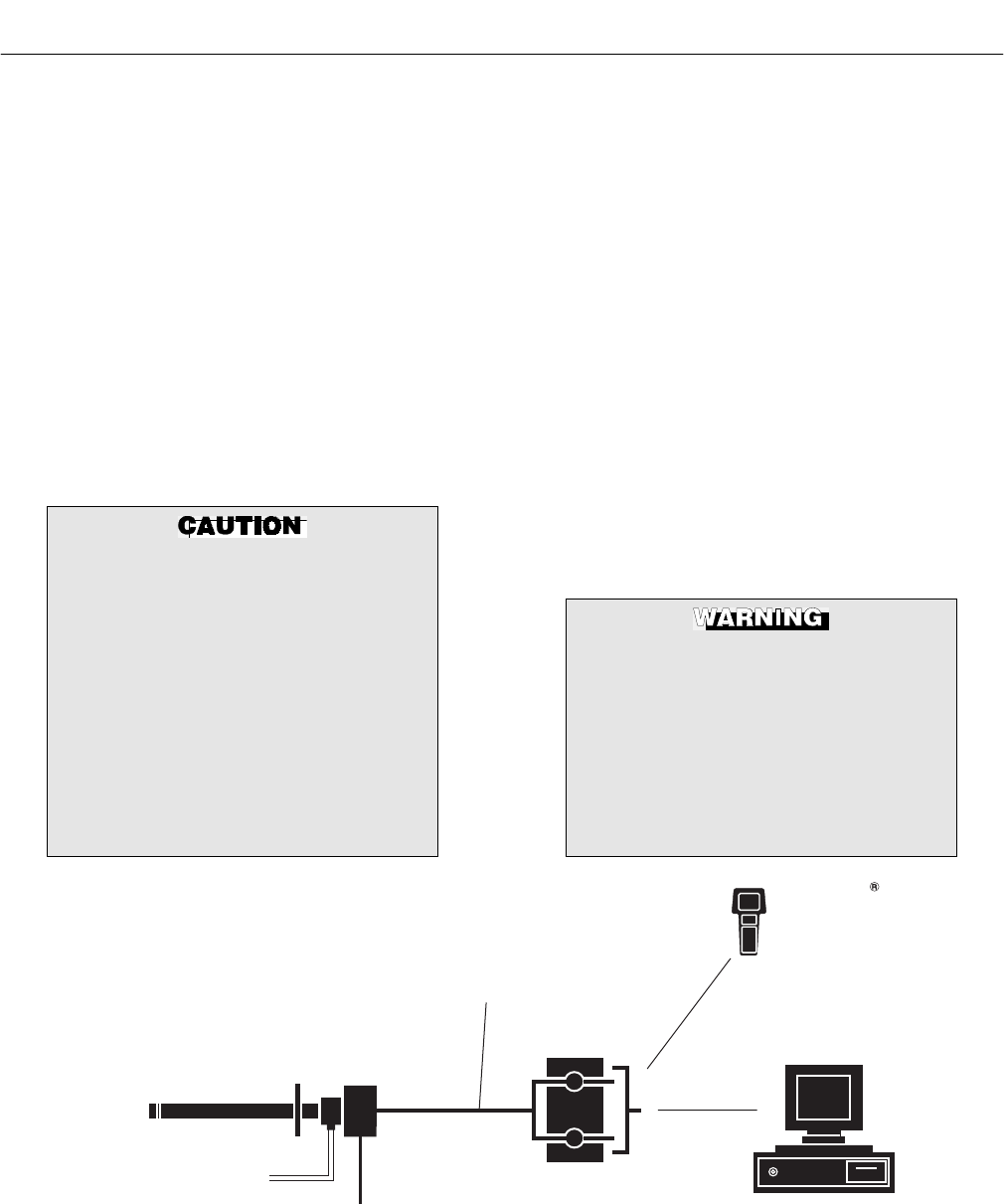
Instruction Manual
IB-106-340C Rev. 4.1
July 2004
1-6 Description and Specifications Rosemount Analytical Inc. A Division of Emerson Process Management
Hazardous Area Oxymitter 4000
(d) Optional IMPS 4000. The Pro-
grammable Logic Controller (PLC)
in the IMPS 4000 provides fault
indications using flashing LEDs
and LCD display messages. Refer
to the IMPS 4000 Intelligent Multi-
probe Test Gas Sequencer manual
for more information.
10. The optional Rosemount 751 remote
mounted LCD display panel is loop-
driven by the 4-20 mA output signal
representing the O2 percentage.
e. Handling the Hazardous Area
Oxymitter 4000
It is important that printed circuit
boards and integrated circuits are
handled only when adequate antistatic
precautions have been taken to pre-
vent possible equipment damage.
The Hazardous Area Oxymitter 4000 is
designed for industrial applications.
Treat each component of the system
with care to avoid physical damage.
Some probe components are made
from ceramics, which are susceptible
to shock when mishandled.
f. System Considerations
Prior to installing your Hazardous Area
Oxymitter 4000, make sure you have all the
components necessary to make the system
installation. Ensure all the components are
properly integrated to make the system
functional.
After verifying that you have all the compo-
nents, select mounting locations and deter-
mine how each component will be placed
in terms of available line voltage, ambient
temperatures, environmental considera-
tions, convenience, and serviceability.
Figure 1-5 shows a typical system wiring.
A typical system installation with integral
electronics is illustrated in Figure 1-6. A
typical system installation with remote elec-
tronics is illustrated in Figure 1-7.
The HART option is not protected by
energy limiting barriers. It must not be
interfaced from within the hazardous
area. The 4-20 mA cables should be
routed and the connections made out-
side the hazardous area. Note that this
is the case even when using the in-
trinsically safe version of the handheld
communicator.
LINE VOLTAGE
2 CALIBRATION GAS LINES
BY CUSTOMER
[300 FT (90 M) MAX]
HAZARDOUS AREA
OXYMITTER 4000
WITH INTEGRAL ELECTRONICS
TERMINATION IN
CONTROL ROOM ASSET MANAGEMENT SOLUTIONS
4-20 MA OUTPUT
(TWISTED PAIR)
HART
MODEL 275/375
HAND HELD
INTERFACE
37270009
Figure 1-5. Hazardous Area Oxymitter 4000 HART Connections and AMS Application
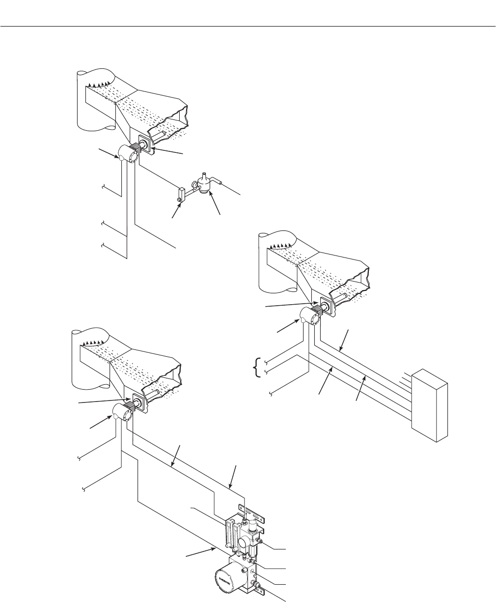
Instruction Manual
IB-106-340C Rev. 4.1
July 2004
Rosemount Analytical Inc. A Division of Emerson Process Management Description and Specifications 1-7
Hazardous Area Oxymitter 4000
CALIBRATION GAS 2
37270014
DUCT
STACK
GASES
CALIBRATION
GAS
ADAPTER
PLATE
LINE
VOLTAGE
LOGIC I/O
INSTRUMENT
AIR SUPPLY
(REFERENCE AIR)
PRESSURE
REGULATOR
FLOWMETER
STANDARD
OXYMITTER
4000
4TO20mA
SIGNAL
*NOTE: THE IMPS 4000 OR SPS 4000 MUST
BE INSTALLED IN A NON-HAZARDOUS,
EXPLOSIVE-FREE ENVIRONMENT.
OXYMITTER
4000
IMPS 4000*
MULTIPROBE
AUTOCALIBRATION
OPTION
IMPS 4000
REFERENCE
AIR
LOGIC I/O
CALIBRATION
GAS
ADAPTER
PLATE
STACK
DUCT
GASES
CALIBRATION GAS 1
CALIBRATION GAS 2
INST. AIR
SUPPLY
LINE
VOLTAGE
4TO20mA
SIGNAL
OXYMITTER
4000
REMOTE MOUNTED SPS 4000*
SINGLE PROBE
AUTOCALIBRATION OPTION
(WITH REFERENCE AIR OPTION)
REFERENCE
AIR
LOGIC I/O
CALIBRATION
GAS
INSTRUMENT AIR SUPPLY
CALIBRATION
GAS 1
LINE VOLTAGE
RELAY OUTPUTS AND
REMOTE CONTACT INPUT
ADAPTER
PLATE
STACK
DUCT
GASES
LINE
VOLTAGE
4TO20mA
SIGNAL
Figure 1-6. Typical System Installation – Oxymitter 4000 with Integral Electronics
1
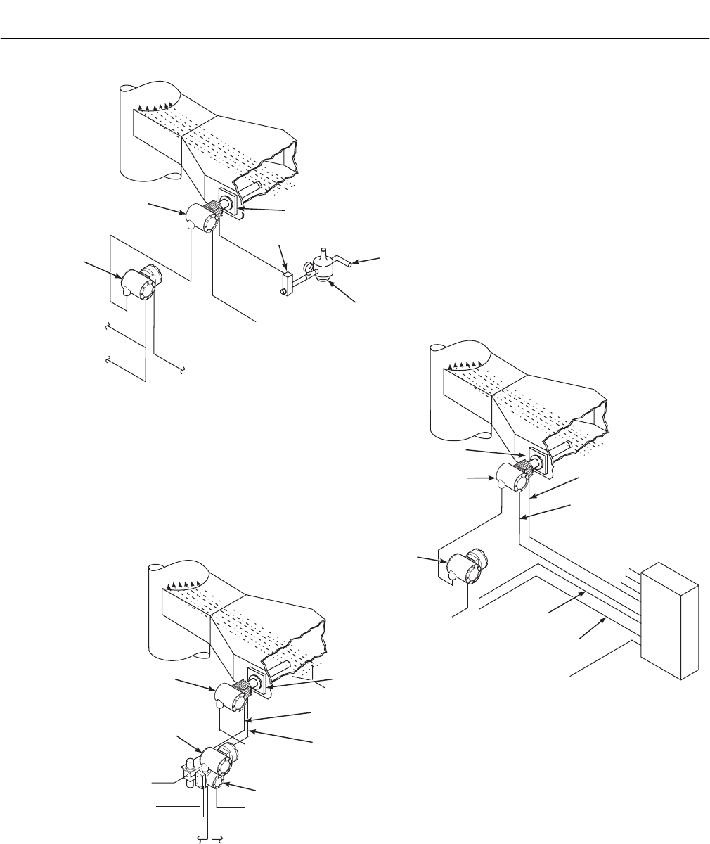
Instruction Manual
IB-106-340C Rev. 4.1
July 2004
1-8 Description and Specifications Rosemount Analytical Inc. A Division of Emerson Process Management
Hazardous Area Oxymitter 4000
DUCT
STACK
GASES
CALIBRATION
GAS
ADAPTER PLATE
LINE
VOLTAGE
LOGIC I/O
INSTRUMENT
AIR SUPPLY
(REFERENCE AIR)
PRESSURE
REGULATOR
FLOWMETER
STANDARD
OXYMITTER 4000
OXYMITTER 4000
OXYMITTER 4000
4TO20mA
SIGNAL
ADAPTER
PLATE
STACK
DUCT
GASES
4-20 mA SIGNAL, RELAY
OUTPUTS, AND REMOTE
CONTACT INPUT
INSTRUMENT AIR SUPPLY
(REFERENCE AIR)
LINE
VOLTAGE
IMPS 4000
REFERENCE AIR
CALIBRATION GAS
ADAPTER PLATE
STACK
DUCT
GASES
CALIBRATIONGAS1
CALIBRATIONGAS2
INST.A
IR
SUPPLY
LINE VOLTAGE
4TO20mA
SIGNAL
REMOTE
ELECTRONICS
REMOTE
ELECTRONICS
LOGIC I/O
LINE VOLTAGE
REMOTE
ELECTRONICS
CALIBRATION GAS 1
CALIBRATION GAS 2
CALIBRATION GAS
REFERENCE AIR
*NOTE: THE IMPS 4000 OR SPS 4000 MUST
BE INSTALLED IN A NON-HAZARDOUS,
EXPLOSIVE-FREE ENVIRONMENT.
SPS 4000
37270006
IMPS 4000*
MULTIPROBE
AUTOCALIBRATION
OPTION
REMOTE MOUNTED SPS 4000*
SINGLE PROBE
AUTOCALIBRATION OPTION
(WITH REFERENCE AIR OPTION)
Figure 1-7. Typical System Installation – Oxymitter 4000 with Remote Electronics
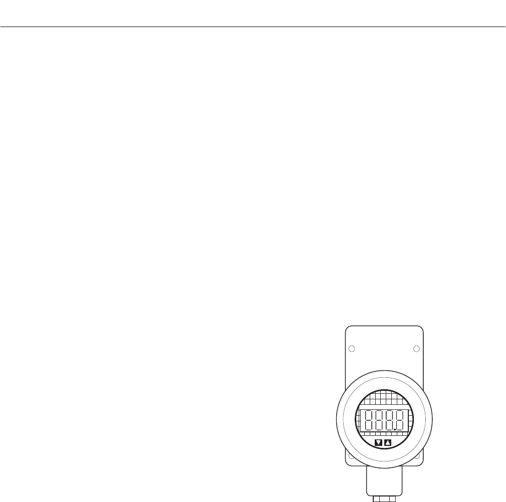
Instruction Manual
IB-106-340C Rev. 4.1
July 2004
Rosemount Analytical Inc. A Division of Emerson Process Management Description and Specifications 1-9
Hazardous Area Oxymitter 4000
A source of instrument air is optional at
the Hazardous Area Oxymitter 4000 for
reference air use. Since the unit can be
equipped with an in-place calibration fea-
ture, provisions can be made to perma-
nently connect calibration gas bottles to the
Hazardous Area Oxymitter 4000.
If the calibration gas bottles will be perma-
nently connected, a check valve is required
next to the calibration fittings on the integral
electronics.
This check valve is to prevent breathing of
the calibration gas line and subsequent flue
gas condensation and corrosion.
The check valve is in addition to the stop
valve in the calibration gas kit and solenoid
valves in the IMPS 4000 or SPS 4000.
NOTE
The integral electronics is rated NEMA
4X (IP66) and is capable of operation
at temperatures up to 85°C (185°F).
The optional LOI is also rated for
operation at temperatures up to 85°C
(185°F). The infrared keypad function-
ality will degrade at temperatures
above 70°C (158°F).
Retain the original packaging for the
Hazardous Area Oxymitter 4000, in
case the components are to be
shipped to another site. This packag-
ing is designed to protect the product.
1-3 IMPS 4000 (OPTIONAL)
If using an IMPS 4000 with a Hazardous Area
Oxymitter 4000, the IMPS 4000 sequencer must
be installed in a non-hazardous, explosive-free
environment.
For further IMPS 4000 information, refer to the
IMPS 4000 Intelligent Multiprobe Test Gas
Sequencer Instruction Bulletin.
1-4 SPS 4000 (OPTIONAL)
If using an SPS 4000 with a Hazardous Area
Oxymitter 4000, the SPS 4000 sequencer must
be installed in a non-hazardous, explosive-free
environment.
For further SPS 4000 information, refer to
the SPS 4000 Single Probe Autocalibration
Sequencer Instruction Bulletin.
1-5 MODEL 751 REMOTE POWDERED LOOP
LCD DISPLAY
The display, Figure 1-8, provides a simple,
economical means to obtain accurate, reliable,
and remote indication of important process vari-
ables. This display operates on the 4-20 mA line
from the Hazardous Area Oxymitter 4000.
Refer to Model 751 remote powered loop LCD
manual for calibration and wiring.
++
++
%
22220059
Figure 1-8. Model 751 Remote Powered Loop
LCD Display
1
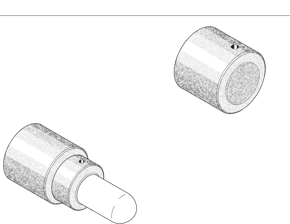
Instruction Manual
IB-106-340C Rev. 4.1
July 2004
1-10 Description and Specifications Rosemount Analytical Inc. A Division of Emerson Process Management
Hazardous Area Oxymitter 4000
1-6 PROBE OPTIONS
a. Flame Arrestor Ceramic Diffusion
Assembly
The flame arrestor ceramic diffusion as-
sembly, Figure 1-9, includes a set of baffles
between the cell and the stack gases. This
keeps 816°C (1500°F) cell temperatures
from igniting unburned fuel in the stack. The
ceramic diffusion assembly is also available
with a dust seal for use with the abrasive
shield assembly.
36220005
Figure 1-9. Flame Arrestor Ceramic Diffusion
Assembly
36220006
Figure 1-10. Flame Arrestor Snubber Diffusion
Assembly
b. Flame Arrestor Snubber Diffusion
Assembly
The flame arrestor snubber diffusion as-
sembly, Figure 1-10, is satisfactory for most
applications. This element is also available
with a dust seal for use with an abrasive
shield.
c. Abrasive Shield Assembly
The abrasive shield assembly, Figure 1-11,
is a stainless-steel tube that surrounds the
probe assembly. The shield protects against
particle abrasion and condensations,
provides a guide for ease of insertion, and
acts as a position support, especially for
longer probes. The abrasive shield
assembly uses a modified diffusor and vee
deflector assembly, fitted with dual dust seal
packing.
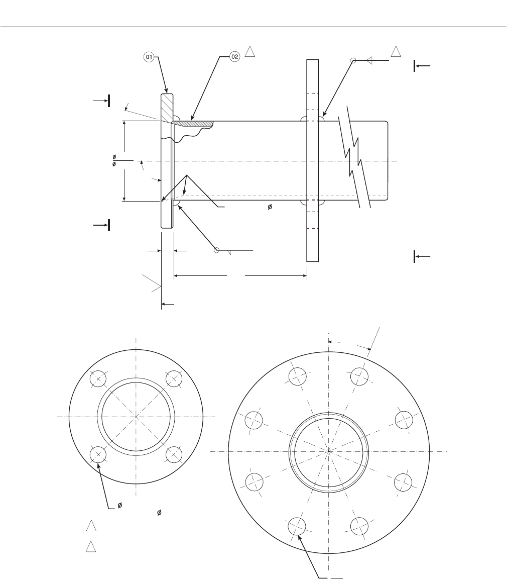
Instruction Manual
IB-106-340C Rev. 4.1
July 2004
Rosemount Analytical Inc. A Division of Emerson Process Management Description and Specifications 1-11
Hazardous Area Oxymitter 4000
VIEW A VIEW B
A
B
A
B
15
o
2.187 1
ON INSIDE BREAK
FOR SMOOTH
ROUNDED EDGE ON
BOTH ENDS
OF CHAMFER
.187
6.00
125
.45 MIN
90
o
3.584
3.554
SKIN CUT FACE FOR 90
o
22.5
o
DIA ON A 7.50 DIA B.C. (REF)
.745
.755
0.75 THRU 4 PLS,
EQ SP ON 4.75 B.C.
NOTES: 1 WELD ON BOTH SIDES WITH EXPANDING
CHILL BLOCK.
2 BEFORE WELDING, BUTT ITEM 2 WITH
ITEM 1 AS SHOWN.
.187
37270015
Figure 1-11. Abrasive Shield Assembly
NOTE
In highly abrasive applications, rotate the shield 90 degrees at normal
service intervals to present a new wear surface to the abrasive flow stream.
1

Instruction Manual
IB-106-340C Rev. 4.1
July 2004
1-12 Description and Specifications Rosemount Analytical Inc. A Division of Emerson Process Management
Hazardous Area Oxymitter 4000
1-7 SPECIFICATIONS
O2 Range:
Standard............................................. 0 to 10% O2, 0 to 25% O2, 0 to 40% O2 (via HART)
Accuracy ............................................ ±0.75% of reading or 0.05% O2, whichever is greater
System Response to Calibration Gas Initial – less than 3 sec., T90 – less than 8 sec.
Temperature Limits:
Process .............................................. 0° to 704°C (32° to 1300°F) up to 1300°C (2400°F) with
optional accessories
Electronics Housing ........................... -40° to 70°C (-40° to 158°F), ambient
Electronics Package .......................... -40° to 85°C (-40° to 185°F) – operating temperature of
electronics inside instrument housing, as measured by
a HART communicator or Rosemount Asset Management
Solutions software
Local Operator Interface ................... -40° to 70°C (-40° to 158°F), ambient
-40° to 85°C (-40° to 185°F), internal [At temperatures
above 70°C (158°F) inside instrument housing, the infrared
keypad will cease to function, but the Oxymitter 4000 will
continue to operate properly.]
Probe Lengths............................................ 18 in. (457 mm), 3 ft (0.91 m), 6 ft (1.83 m)
Mounting and Mounting Position ............... Vertical or horizontal;
a spool piece (P/N 3D39761G02) is available to offset
transmitter housing from hot ductwork.
Materials:
Probe.................................................. Wetted or welded parts - 316L stainless steel (SS)
Non-wetted parts - 304 SS, low-copper aluminum
Electronics Enclosure ........................ Low-copper aluminum
Calibration.................................................. Manual, semi-automatic, or automatic
Calibration Gas Mixtures Recommended.. 0.4% O2, Balance N2
8% O2, Balance N2
Calibration Gas Flow ................................. 5 scfh (2.5 l/m)
Reference Air............................................. 0.5 scfh (0.25 l/hr), clean, dry, instrument-quality air
(20.95% O2), regulated to 5 psi (34 kPa)
Electronics ................................................. NEMA 4X, IP66 with fitting and pipe on reference exhaust
port to clear dry atmosphere
Line Voltage ............................................... 90-250 VAC, 48/62 Hz; 3/4 in.-14 NPT conduit port.
Pollution Degree ........................................ 2
Over Voltage Category .............................. II
Relative Humidity ....................................... 5 to 95% (non-condensing)
Signals:
Analog Output/HART ......................... 4-20 mA isolated from power supply, 950 ohms
maximum load
Logic I/O............................................. Two-terminal logic contact configurable as either an alarm
output or as a bi-directional calibration handshake signal to
IMPS 4000 or SPS 4000.
Self-powered (+5 V), in series with 340 ohms
Conduit port — 3/4 in.-14 NPT (for analog output
and logic I/O signal lines)

Instruction Manual
IB-106-340C Rev. 4.1
July 2004
Rosemount Analytical Inc. A Division of Emerson Process Management Description and Specifications 1-13
Hazardous Area Oxymitter 4000
Power Requirements:
Probe Heater...................................... 175 W nominal
Electronics.......................................... 10 W nominal
Maximum ........................................... 500 W
Fisher-Rosemount has satisfied all obligations coming from the European legislation to harmonize
the product requirements in Europe.
1-8 HAZARDOUS AREA CERTIFICATIONS
a. Hazardous Area Oxymitter 4000 with Integral Electronics
KEMA/ATEX II 2 G EEx d IIB+H2 T6 (Elect Comp) / T2 (Probe)
CSA Class I, Division 1, Groups B, C, D T2
Class I, Zone 1, Ex d IIB+H2 T2
Class I, Zone 1, AEx d IIB+H2 T2
FM Class I, Division 1, Groups B, C, D T2
Class I, Zone 1, AEx d IIB+H2 T2
b. Hazardous Area Oxymitter 4000 with Remote Electronics
KEMA/ATEX II 2 G EEx d IIB+H2 T2
II 2 G EEx de IIB+H2 T6
(Remote Probe)
(Remote Electronics)
CSA Class I, Zone 1, Ex d IIB+H2 T2
Class I, Zone 1, Ex de IIB+H2 T6
Class I, Zone 1, AEx d IIB+H2 T2
Class I, Zone 1, AEx de IIB+H2 T6
(Remote Probe)
(Remote Electronics)
(Remote Probe)
(Remote Electronics)
FM Class I, Zone 1, AEx d IIB+H2 T2
Class I, Zone 1, AEx de IIB+H2 T6
(Remote Probe)
(Remote Electronics)
1

Instruction Manual
IB-106-340C Rev. 4.1
July 2004
1-14 Description and Specifications Rosemount Analytical Inc. A Division of Emerson Process Management
Hazardous Area Oxymitter 4000
Table 1-1. Product Matrix
OXT4C OXYMITTER 4000 - EXPLOSION PROOF - IN SITU OXYGEN TRANSMITTER
Explosion Proof Oxygen Transmitter - Instruction Book
Code Sensing Probe Type with Flame Arrestor
1 Ceramic Diffusion Element Probe (ANSI 3 in. 150 lbs)
2 Snubber Diffusion Element (ANSI 3 in. 150 lbs)
3 Ceramic Diffusion Element Probe (DIN 2527) - 1/4 in. Tube Fittings
4 Snubber Diffusion Element (DIN 2527) - 1/4 in. Tube Fittings
5 Ceramic Diffusion Element Probe (JIS)
6 Snubber Diffusion Element (JIS)
7 Ceramic Diffusion Element (ANSI 3 in. 300 lbs)
8 Ceramic Diffusion Element (ANSI 4 in. 300 lbs)
Code Probe Assembly
0 18 in. (457 mm) Probe
1 18 in. (457 mm) Probe with 3 ft (0.91 m) Bypass
2 18 in. (457 mm) Probe with Abrasive Shield(1)
3 3 ft (0.91 m) Probe
4 3 ft (0.91 m) Probe with Abrasive Shield(1)
5 6 ft (1.83 m) Probe
6 6 ft (1.83 m) Probe with Abrasive Shield(1)
Code Mounting Adapter - Stack Side
0 No Adapter Plate (“0” must be chosen under “Mounting Adapter - Probe Side” below)
1 New Installation - Square weld plate with studs
2 Model 218 Mounting Plate (with Model 218 Shield Removed)
3 Competitor’s Mount(2)
Code Mounting Adapter - Probe Side
0 No Adapter Plate
1 Probe Only (ANSI)
2 New Bypass or New Abrasive Shield (ANSI)
4 Probe Only (DIN)
5 New Bypass or New Abrasive Shield (DIN)
7 Probe Only (JIS)
8 New Bypass or New Abrasive Shield (JIS)
Code Electronic Housing and Filtered Customer Termination - NEMA 4X, IP66
11 HART® Integral Electronics, Standard Filtered Termination,
ATEX Certification
12 HART® Integral Electronics, Transient Protected Filtered Termination,
ATEX Certification
13 HART® Remote Electronics (requires cable), Standard Filtered Termination,
ATEX Certification
14 HART® Remote Electronics (requires cable), Transient Protected Termination,
ATEX Certification
21 HART® Integral Electronics, Standard Filtered Termination,
CSA/FM Certification
22 HART® Integral Electronics, Transient Protected Termination,
CSA/FM Certification
23 HART® Remote Electronics (requires cable), Standard Filtered Termination,
CSA/FM Certification
24 HART® Remote Electronics (requires cable), Transient Protected Termination,
CSA/FM Certification
OXT4C331111 Example
Instruction Manual
IB-106-340C Rev. 4.1
July 2004
Rosemount Analytical Inc. A Division of Emerson Process Management Description and Specifications 1-15
Hazardous Area Oxymitter 4000
Table 1-1. Product Matrix (Continued)
Continued Code Operator Interface(3)
1 Membrane Keypad - HART Capable
2 Membrane Keypad - HART Capable, Glass Window
3 LOI - HART Capable, Glass Window, English Only
Code Language
1 English
2German
3 French
4 Spanish
5 Italian
Code Termination Filtering
00 No Option - Specified as part of Electronic Housing
Code Calibration Accessories
00 No Hardware
01 Cal/Ref Flowmeters and Ref Pressure Regulator
02 IMPS 4000 (Safe Area Only)
03 SPS 4000 Remote Mounted (Safe Area Only)
Code Hazardous Area Approval
00 Specified as part of the electronics
Code Electronics to Probe Cable
00 No Cable
10 20 ft (6 m) Cable
11 40 ft (12 m) Cable
12 60 ft (18 m) Cable
13 80 ft (24 m) Cable
14 100 ft (30 m) Cable
15 150 ft (45 m) Cable
16 200 ft (61 m) Cable
Continued 1 3 00 03 00 10 Example
NOTES:
(1)Recommended uses: High velocity particulates in flue stream, installation within 11.5 ft (3.5 m) of soot blowers or heavy salt cake buildup.
Applications: Pulverized coal, recovery boilers, lime kiln.
(2)Where possible, specify ANSI, DIN, or JIS designation; otherwise, provide details of the existing mounting plate as follows:
Plate with studs Bolt circle diameter, number, and arrangement of studs; stud thread; and stud height above mounting plate.
Plate without studs Bolt circle diameter, number, and arrangement of holes; thread; and depth of stud mounting plate with accessories.
(3)Startup, calibration, and operation can be implemented using the standard membrane keypad. Remote access and additional functionality
available via HART Communications [Model 275/375 Handheld Communicator with Hazardous Area Oxymitter 4000 device descriptor (DD)]
required.
1

Instruction Manual
IB-106-340C Rev. 4.1
July 2004
1-16 Description and Specifications Rosemount Analytical Inc. A Division of Emerson Process Management
Hazardous Area Oxymitter 4000
Table 1-2. Calibration Components
Part
Number Description
1A99119G01 Two disposable calibration gas bottles — 0.4% and 8% O2,
balance nitrogen — 550 liters each*
1A99119G02 Two pressure regulators for calibration gas bottles
1A99119G03 Bottle rack
*Calibration gas bottles cannot be shipped via airfreight.
When the bottles are used with “CALIBRATION RECOMMENDED” features, the bottles should
provide 2 to 3 years of calibrations in normal service.
Table 1-3. Intelligent Multiprobe Test Gas Sequencer Versions
Part
Number Description
Number of Hazardous Area
Oxymitter 4000 Units
3D39695G01 IMPS 1
3D39695G02 IMPS 2
3D39695G03 IMPS 3
3D39695G04 IMPS 4
3D39695G05 IMPS w/115 V Heater 1
3D39695G06 IMPS w/115 V Heater 2
3D39695G07 IMPS w/115 V Heater 3
3D39695G08 IMPS w/115 V Heater 4
3D39695G09 IMPS w/220 V Heater 1
3D39695G10 IMPS w/220 V Heater 2
3D39695G11 IMPS w/220 V Heater 3
3D39695G12 IMPS w/220 V Heater 4
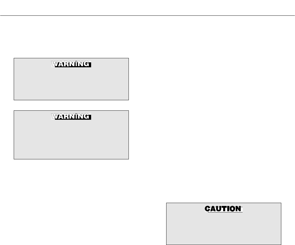
Instruction Manual
IB-106-340C Rev. 4.1
July 2004
Rosemount Analytical Inc. A Division of Emerson Process Management Installation 2-1
Hazardous Area Oxymitter 4000
SECTION 2
INSTALLATION
The Hazardous Area Oxymitter 4000
and probe abrasive shield are heavy.
Use proper lifting and carrying proce-
dures to avoid personal injury.
Install all protective equipment covers
and safety ground leads after installa-
tion. Failure to install covers and
ground leads could result in serious
injury or death.
2-1 MECHANICAL INSTALLATION
a. Selecting Location
1. The location of the Hazardous Area
Oxymitter 4000 in the stack or flue is
most important for maximum accuracy
in the oxygen analyzing process. The
Hazardous Area Oxymitter 4000 must
be positioned so the gas it measures
is representative of the process. Best
results are normally obtained if the
Hazardous Area Oxymitter 4000 is
positioned near the center of the duct
(40 to 60% insertion). Longer ducts
may require several Hazardous Area
Oxymitter 4000 units since the O2 can
vary due to stratification. A point too
near the wall of the duct, or the inside
radius of a bend, may not provide a
representative sample because of the
very low flow conditions. The sensing
point should be selected so the proc-
ess gas temperature falls within a
range of 0° to 704°C (32° to 1300°F).
Figure 2-1 through Figure 2-5 provide
mechanical installation references.
The ambient temperature of the elec-
tronics housing must not exceed 70°C
(150°F). For higher ambient tempera-
tures, we recommend the remote
mounted electronics option.
NOTE
At temperatures up to 85°C (185°F)
inside the housing, the infrared keypad
will cease to function, but the transmit-
ter will continue to operate properly.
2. Check the flue or stack for holes and
air leakage. The presence of this con-
dition will substantially affect the accu-
racy of the oxygen reading. Therefore,
either make the necessary repairs or
install the Hazardous Area Oxymitter
4000 upstream of any leakage.
3. Ensure the area is clear of internal and
external obstructions that will interfere
with probe installation and access to
the membrane keypad or LOI. Allow
adequate clearance for removal of the
Hazardous Area Oxymitter 4000
(Figure 2-1 or Figure 2-3).
Do not allow the temperature of the
Hazardous Area Oxymitter 4000 elec-
tronics to exceed 85°C (185°F) or dam-
age to the unit may result.
b. Probe Installation
1. Ensure all components are available to
install the Hazardous Area Oxymitter
4000. If equipped with a ceramic dif-
fuser, make sure the diffuser is not
damaged.
2. The Hazardous Area Oxymitter 4000
probe may be installed intact, as it is
received.
NOTE
An abrasive shield is recommended
for high velocity particulates in the
flue stream (such as those in coal-
fired boilers, kilns, and recovery
boilers).
3. Weld or bolt mounting plate (Figure
2-5) onto the duct.
2
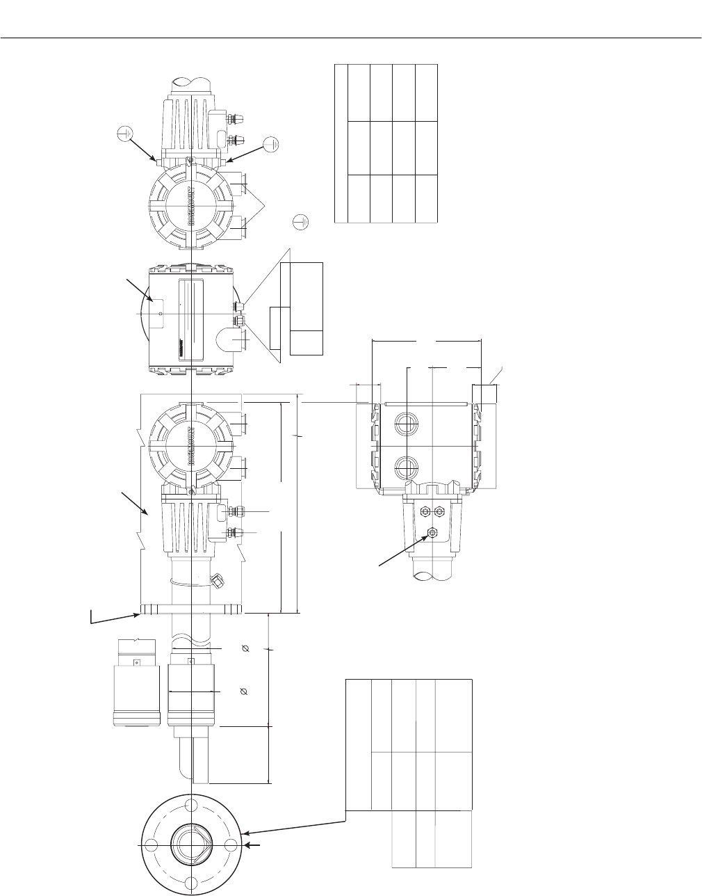
Instruction Manual
IB-106-340C Rev. 4.1
July 2004
2-2 Installation Rosemount Analytical Inc. A Division of Emerson Process Management
Hazardous Area Oxymitter 4000
COVER REMOVAL & ACCESS
305
305
(12)
(12)
ADD TO DIM “A”
FOR PROBE WITH
CERAMIC DIFFUSER
95 (3.8)
WITH
SNUBBER
DIFFUSER
DIM "A"
66
(2.6)
76
(3.0)
DIM "B"
REMOVAL ENVELOPE
ELEC CONN
3/4 NPT
6 mm TUBE
JIS
ANSI ( ) TUBE6.35 1/4
DIN 6.35 (1/4) TUBE
CAL GAS
REF AIR
BOTTOM VIEW
P
S
U
E
I
T
P
I
C
R
H
W
E
N
T
H
G
C
K
E
N
I
-
E
E
R
W
A
V
I
S
O
L
P
-
X
O
M
T
A
G
N
I
N
-
R
I
T
L
A
I
V
E
-
E
E
H
343 (13.5)
GAS
CAL.
500 VA
R
SERIAL NO.
TAG N O.
OXYMITTER 4000
VOLTS: WATTS:
OUTPUT: LINE FUSE:
Rosemount Analytical Inc.
Orrville,OH 44667-0901
85-264 VAC 48-62 Hz
TM
800-433-6076
4-20 mA
R
5 Amps
TM
HART
SMART FAMILY
REF.
GAS
-
-
R
H
G
T
I
N
E
W
H
C
I
T
K
E
P
E
A
I
T
C
U
E
V
L
I
-
M
N
I
N
L
O
A
R
P
N
I
X
E
-
W
G
E
S
I
V
A
T
O
S
E
H
E
R
P
167
(6.58)
(2.89)
73
(1.55)
39
PROCESS FLOW MUST BE IN
THIS DIRECTION WITH RESPECT
TO DEFLECTOR 3534B48G01
INSULATE IF EXPOSED TO
AMBIENT WEATHER CONDITIONS
THESE FLAT FACED FLANGES ARE
MANUFACTURED TO ANSI, DIN, & JIS BOLT
PATTERNS; AND ARE NOT PRESSURE RATED.
ALL DIMENSIONS ARE IN MILLIMETERS
WITH INCHES IN PARENTHESES UNLESS
OTHERWISE NOTED.
NOTES:
0.062 IN. THK GASKET
CERTIFICATION
APPROVED
LABEL
EXTERNAL
EARTH
EXTERNAL
EARTH
VENT
REF. AIR
INTERNAL
EARTH
TABLE 1 MOUNTING FLANGE
(GASKET INCLUDED)
(4) HOLES
EQ SP
ON BC
HOLE DIA
FLANGE
DIA
DIN
ANSI
152.4
(6.00)
190
(7.5)
19 (.75)
170
(6.69)
18 (.71)
210
(8.25)
TABLE 2 INSTALLATION/REMOVAL
DIM "A"
3 FT
6 FT
PROBE
18 IN.
DIM "B"
2174
(85.6)
1831
(72.1)
917
(36.1)
1448
(57.0)
803
(31.6)
460
(18.1)
35910002
Figure 2-1. Hazardous Area Oxymitter 4000 Probe Installation
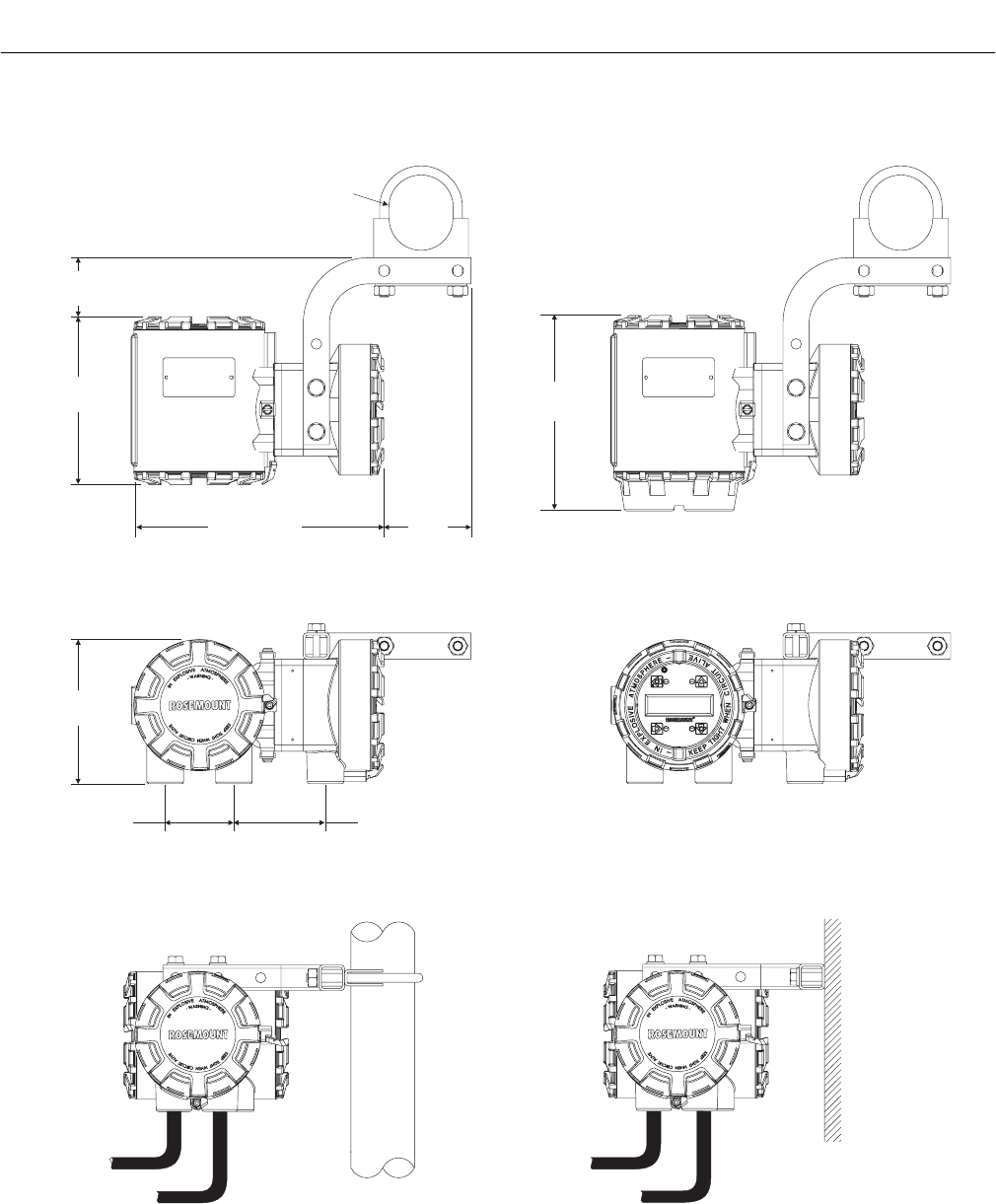
Instruction Manual
IB-106-340C Rev. 4.1
July 2004
Rosemount Analytical Inc. A Division of Emerson Process Management Installation 2-3
Hazardous Area Oxymitter 4000
()
56.0
2.21
()
164.6
6.48
246.9 9.72() 84.6
3.33()
62.0
(2.44)
DIA.
189.8
7.47()
140.2
5.52()
66.5
2.62() 93.5 ( )3.68
PIPE MOUNT
CONFIGURATION
REMOTE ELECTRONICS
WITH LOI AND WINDOW COVER
REMOTE ELECTRONICS
WITH MEMBRANE KEYPAD AND BLIND COVER
37270013
WALL MOUNT
CONFIGURATION
NOTE: ALL DIMENSIONS ARE IN
MILLIMETERS WITH
INCHES IN PARENTHESES.
Figure 2-2. Hazardous Area Oxymitter 4000 Remote Electronics Installation
2
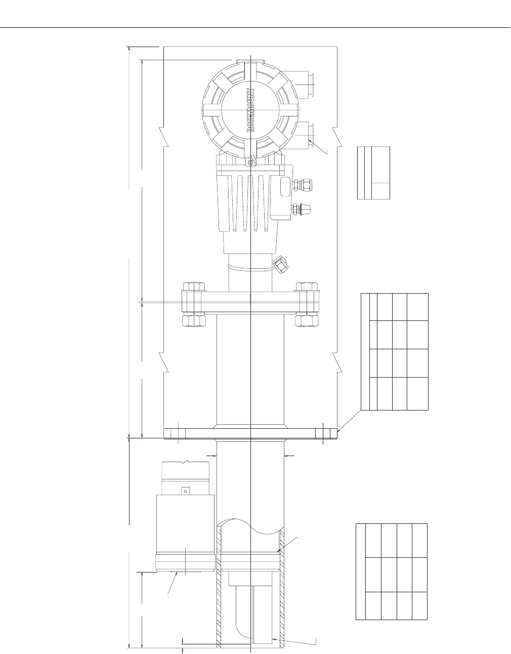
Instruction Manual
IB-106-340C Rev. 4.1
July 2004
2-4 Installation Rosemount Analytical Inc. A Division of Emerson Process Management
Hazardous Area Oxymitter 4000
P
S
U
E
I
T
P
I
C
R
H
W
E
N
T
H
G
C
K
E
N
I
-
E
E
R
W
A
V
I
S
O
L
P
-
X
O
M
T
A
G
N
I
N
-
R
I
T
L
A
I
V
E
-
E
E
H
DEFLECTOR ASSY
3 FT
18 IN
PROBE
TABLE 3 INSTALLATION/REMOVAL
6 FT
(33.2)
843
(69.4)
1762
387
(15.3)
DIM "A"
1367
(53.8)
2287
(90.0)
912
(35.9)
DIM "B"
DIFFUSER/DUST
SEAL ASSY
*ADD CHECK VALVE IN CAL GAS LINE
3/4 NPT ELECTRICAL CONNECTION
REF AIR
CAL GAS*
ANSI
DIN
JIS
1/4 IN. TUBE
1/4 IN. TUBE
6 mm TUBE
GAS
CAL.
SNUBBER/DUST SEAL
ASSEMBL
Y
5
(0.2)
91 (3.6) DIA
NOMINAL
99
(3.9)
DIM "A"
NOTES:
REMOVAL ENVELOPE
DIM "B"
178
(7.00)
343
(13.50)
35910003
(8) HOLES
EQ SP
ON BC
-3D39003
TABLE 4 ABRASIVE SHIELD
HOLE
DIA
FLANGE
DIA
229
(9.00)
235
(9.25)
235
(9.25)
19
(0.75)
19
(0.75)
24
(0.94)
190
(7.48)
190
(7.50)
190
(7.48)
FLANGE ANSI JIS DIN
THESE FLAT FACED FLANGES ARE MANUFACTURED TO ANSI, DIN, & JIS BOLT
PATTERNS AND NOT PRESSURE RATED.
ALL DIMENSIONS ARE IN MILLIMETERS WITH INCHES IN PARENTHESES.
Figure 2-3. Hazardous Area Oxymitter 4000 Probe with Abrasive Shield
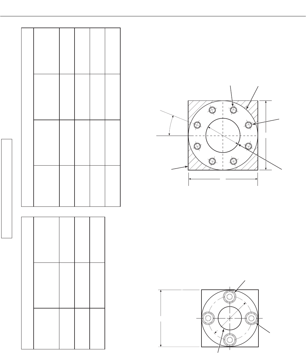
Instruction Manual
IB-106-340C Rev. 4.1
July 2004
Rosemount Analytical Inc. A Division of Emerson Process Management Installation 2-5
Hazardous Area Oxymitter 4000
22.5
o
BC
8 THREADED HOLES
EQUALLY SPACED ON
D DIA B.C.
ABRASIVE SHIELD
FLANGE O.D.
A
A
TABLE V. MOUNTING PLATE DIMENSIONS FOR
HAZARDOUS AREA OXYMITTER 4000 TABLE VI. MOUNTING PLATE DIMENSIONS FOR HAZARDOUS AREA
OXYMITTER 4000 WITH ABRASIVE SHIELD
DIMENSIONS
MM
(in.)
DIMENSIONS
MM
(in.)
ANSI ANSI
DIN DIN JIS
"A" "A"
"B"
STUD SIZE
"B"
DIA
"D"
DIA B.C.
“C"
DIA B.C.
"C"
THREAD
197
(7.75)
229
(9.00)
0.625-11 121
(4.75)
191
(7.50)
152.4
(6.00) 0.625-11
216
(8.50)
235
(9.25)
M16x2 100
(3.94)
190
(7.48)
170.0
(6.69) M16x2
235
(9.25)
125
(4.92)
200
(7.89)
M20 x 2.5
MOUNTING PLATE FOR
HAZARDOUS AREA OXYMITTER 4000
WITH ABRASIVE SHIELD
MOUNTING PLATE FOR
HAZARDOUS AREA OXYMITTER 4000
CROSSHATCHED AREA IN
4 CORNERS MAY BE USED
TO PROVIDE ADDITIONAL
HOLES FOR FIELD BOLTING
OF PLATE TO OUTSIDE
WALL SURFACE.
4 STUDS,
LOCKWASHERS AND
NUTS EQUALLY
SPACED ON
C DIA B.C.
A
82.6
(3.25) DIA
B
NOTE: DIMENSIONS ARE IN MILLIMETERS
WITH INCHES IN PARENTHESES.
27540003
C
MOUNTING PLATE OUTLINE
Figure 2-4. Hazardous Area Oxymitter 4000 Mounting Plate Dimensions
2
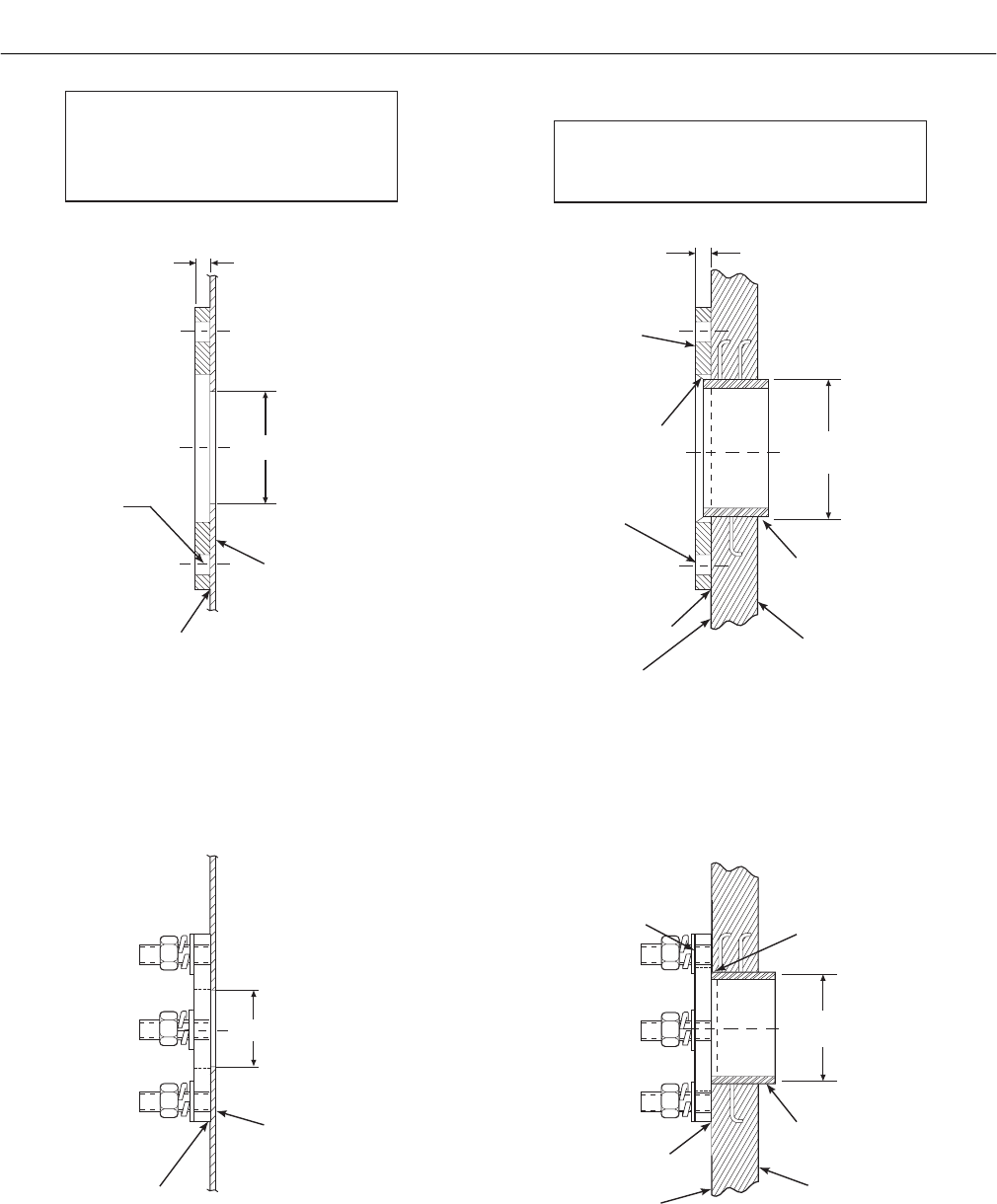
Instruction Manual
IB-106-340C Rev. 4.1
July 2004
2-6 Installation Rosemount Analytical Inc. A Division of Emerson Process Management
Hazardous Area Oxymitter 4000
NOTE: ALL MASONRY STACK WORK AND JOINTS EXCEPT
ADAPTOR PLATE NOT FURNISHED BY ROSEMOUNT.
INSTALLATION FOR MASONRY
WALL STACK CONSTRUCTION
INSTALLATION FOR METAL
WALL STACK OR DUCT
CONSTRUCTION
13 (0.50)
95 (3.75)
MIN DIA HOLE
IN WALL
STACK OR DUCT
METAL WALL
MTG HOLES
SHOWN ROTATED
45 OUT OF
TRUE POSITION
o
WELD OR BOLT MOUNTING
PLATE TO METAL WALL
OF STACK OR DUCT.
JOINT MUST BE AIRTIGHT.
13 (0.50)
114 (4.50)
O.D. REF
PIPE 4.00 IN. SCHED 40
PIPE SLEEVE (NOT
BY ROSEMOUNT)
LENGTH BY CUSTOMER
MASONRY
STACK WALL
OUTSIDE WALL
SURFACE
JOINT MUST
BE AIRTIGHT
MTG HOLES
SHOWN ROTATED
45 OUT OF
TRUE POSITION
o
FIELD WELD
PIPE TO
MOUNTING PLATE
BOLT MOUNTING
PLATE TO OUTSIDE
WALL SURFACE
NOTE: DIMENSIONS IN MILLIMETERS WITH
INCHES IN PARENTHESES.
82.5 (3.25)
MIN DIA HOLE
IN WALL
STACK OR DUCT
METAL WALL
WELD OR BOLT MOUNTING
PLATE TO METAL WALL
OF STACK OR DUCT.
JOINT MUST BE AIRTIGHT.
FIELD WELD
PIPE TO
MOUNTING PLATE
102 (4.0)
O.D. REF
PIPE 3.5 IN. SCHED 40
PIPE SLEEVE (NOT
BY ROSEMOUNT)
LENGTH BY CUSTOMER
MASONRY
STACK WALL
OUTSIDE WALL
SURFACE
JOINT MUST
BE AIRTIGHT
BOLT MOUNTING
PLATE TO OUTSIDE
WALL SURFACE
PROBE MOUNTING
ABRASIVE SHIELD MOUNTING
27540004
Figure 2-5. Hazardous Area Oxymitter 4000 Mounting Plate Installation
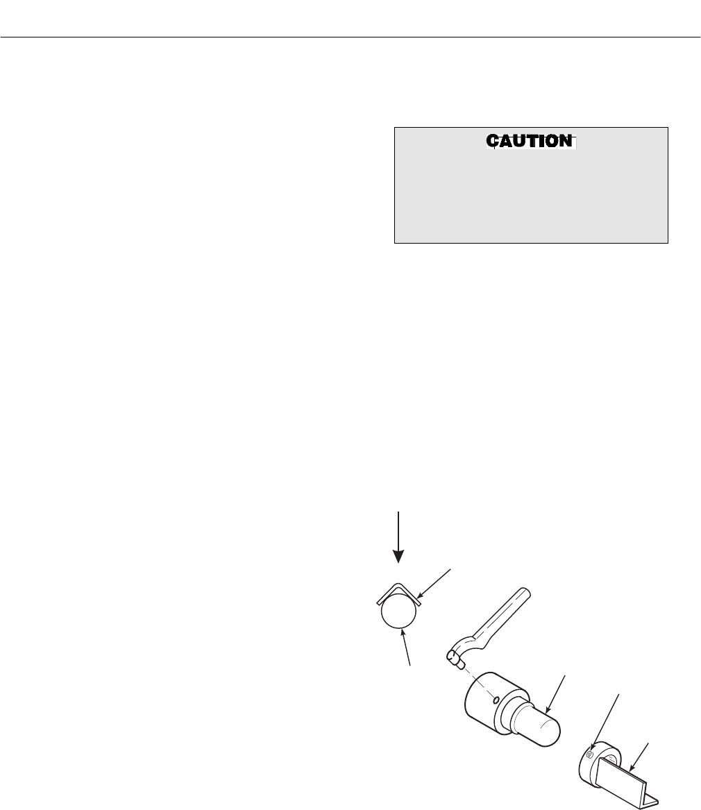
Instruction Manual
IB-106-340C Rev. 4.1
July 2004
Rosemount Analytical Inc. A Division of Emerson Process Management Installation 2-7
Hazardous Area Oxymitter 4000
4. If using the optional ceramic diffusion
element, the vee deflector must be cor-
rectly oriented. Before inserting the
Hazardous Area Oxymitter 4000, check
the direction of flow of the gas in the
duct. Orient the vee deflector so the
apex points upstream toward the flow
(Figure 2-6). This may be done by
loosening the setscrews and rotating
the vee deflector to the desired posi-
tion. Retighten the setscrews.
5. In vertical installations, ensure the
system cable drops vertically from the
Hazardous Area Oxymitter 4000 and
the conduit is routed below the level of
the electronics housing. This drip loop
minimizes the possibility that moisture
will damage the electronics. See Figure
2-7.
6. If the system has an abrasive shield,
check the dust seal gaskets. The joints
in the two gaskets must be staggered
180 degrees. Make sure the gaskets
are in the hub grooves as the Hazard-
ous Area Oxymitter 4000 slides into the
15 degree forcing cone in the abrasive
shield.
NOTE
If process temperatures will exceed
200°C (392°F), use anti-seize com-
pound on the stud threads to ease
future removal of the Hazardous Area
Oxymitter 4000.
7. Insert probe through the opening in the
mounting plate and bolt the unit to the
plate.
NOTE
To maintain CE compliance, ensure a
good connection exists between the
mounting plate studs or earthing
screws on electronics housing and
earth.
8. Ensure the Hazardous Area Oxymitter
4000 is properly earthed by way of
both internal and external points.
Uninsulated stacks or ducts may
cause ambient temperatures around
the electronics to exceed 85°C (185°F),
which may cause overheating damage
to the electronics.
9. If duct work insulation is removed for
Hazardous Area Oxymitter 4000 probe
mounting, make sure the insulation is
replaced afterward. See Figure 2-7.
NOTE
For probe temperatures that will exceed
85°C (185°F), we recommend the remote
mounted electronics option.
10. Ensure the probe installation does not
obscure the warnings on the housing
covers.
VEE
DEFLECTOR
VEE
DEFLECTOR
CERAMIC
DIFFUSION
ELEMENT
SETSCREW
FILTER
GAS FLOW
DIRECTION
APEX
27540009
Figure 2-6. Orienting the Optional Vee Deflector
2
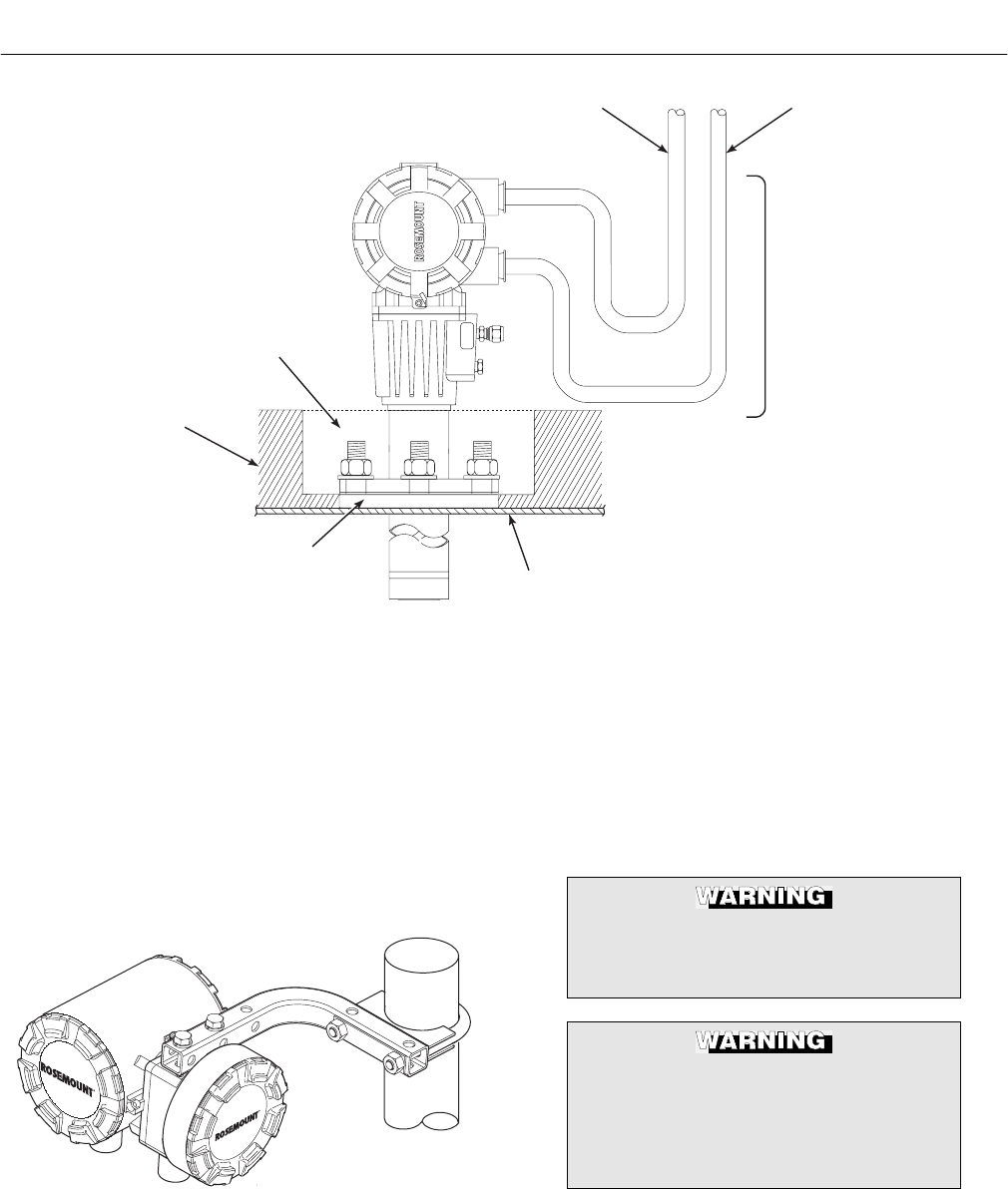
Instruction Manual
IB-106-340C Rev. 4.1
July 2004
2-8 Installation Rosemount Analytical Inc. A Division of Emerson Process Management
Hazardous Area Oxymitter 4000
P
S
U
E
I
T
P
I
C
R
H
W
E
N
T
H
G
C
K
E
N
I
-
E
E
R
W
A
V
I
S
O
L
P
-
X
O
M
T
A
G
N
I
N
-
R
I
T
L
A
I
V
E
-
E
E
H
GAS
CAL.
DRIP
LOOP
LOGIC I/O,
4-20 mA SIGNAL
LINE
VOLTAGE
REPLACE INSULATION
AFTER INSTALLING
HAZARDOUS AREA
OXYMITTER 4000
INSULATION
MOUNTING
PLATE STACK OR DUCT
METAL WALL
26310010
Figure 2-7. Installation with Drip Loop and Insulation Removal
c. Remote Electronics Installation
For a Hazardous Area Oxymitter 4000 with
the remote electronics option, install the
probe according to the instructions in para-
graph 2-1.b. Install the remote electronics
unit on a wall, stand pipe, or similar struc-
ture (Figure 2-2 and Figure 2-8).
37260016
Figure 2-8. Remote Electronics Mounting
2-2 ELECTRICAL INSTALLATION (FOR
HAZARDOUS AREA OXYMITTER 4000
WITH INTEGRAL ELECTRONICS)
All wiring must conform to local and national
codes.
Disconnect and lock out power before
connecting the unit to the power
supply.
Install all protective equipment covers
and safety ground leads after installa-
tion. Failure to install covers and
ground leads could result in serious
injury or death.
Instruction Manual
IB-106-340C Rev. 4.1
July 2004
Rosemount Analytical Inc. A Division of Emerson Process Management Installation 2-9
Hazardous Area Oxymitter 4000
To meet the Safety Requirements of
IEC 1010 (EC requirement), and ensure
safe operation of this equipment, con-
nection to the main electrical power
supply must be made through a circuit
breaker (min 10 A) which will discon-
nect all current-carrying conductors
during a fault situation. This circuit
breaker should also include a me-
chanically operated isolating switch. If
not, then another external means of
disconnecting the supply from the
equipment should be located close by.
Circuit breakers or switches must
comply with a recognized standard
such as IEC 947.
The probe and probe abrasive shield
are heavy. Use proper lifting and car-
rying procedures to avoid personnel
injury.
To maintain explosion-proof protec-
tion, all cable entry devices and
blanking elements for unused aper-
tures must be certified flameproof,
suitable for the conditions of use and
be properly installed.
a. Remove screw (18, Figure 9-3), cover lock
(19), and captive washer (20). Remove
cover (17) from terminal block (15).
b. Connect Line Voltage. Connect the line, or
L1, wire to the L1 terminal and the neutral,
or L2 wire, to the N terminal. See Figure
2-9. The Hazardous Area Oxymitter 4000
automatically will configure itself for 90-250
VAC line voltage and 50/60 Hz. To avoid a
shock hazard, the power terminal cover
must be installed.
c. Connect 4-20 mA Signal and Calibration
Handshake/Logic I/O Leads (Figure 2-9).
1. 4-20 mA Signal. The 4-20 mA signal
represents the O2 value and can also
operate the Model 751 Loop LCD Dis-
play or any other loop powered display.
Superimposed on the 4-20 mA signal is
HART information that is accessible
through a Model 275/375 Handheld
Communicator or AMS software.
If using an IMPS 4000 or an SPS 4000,
install it in a non-hazardous, explosive-
free environment.
2. Calibration Handshake/Logic I/O. The
output signal can be used to trigger an
alarm or to provide a calibration hand-
shake signal to an IMPS or SPS 4000.
If autocalibration is not utilized, a
common bi-directional logic contact is
provided for any of the equipment
alarms listed in Table 8-1. The assign-
ment of alarms that will actuate this
contact is modified by one of seven
additional configuration settings (mode
1 through mode 7) listed in Table 4-1.
The logic contact is self-powered,
+5 VDC, with a 340 ohm series resis-
tance. An interposing relay is required
if the logic contact will annunciate a
higher voltage device, such as a light
or horn. An interposing relay may also
be required for certain DCS input
cards. A Potter & Brumfield model
R10S-E1Y1-J1.0K 3.2 mA DC (or
equal) interposing relay will be
mounted where the contact wires
terminate in the control/relay room.
d. Install cover (17, Figure 9-3) and secure
with captive washer (20), cover lock (19),
and screw (18).
2
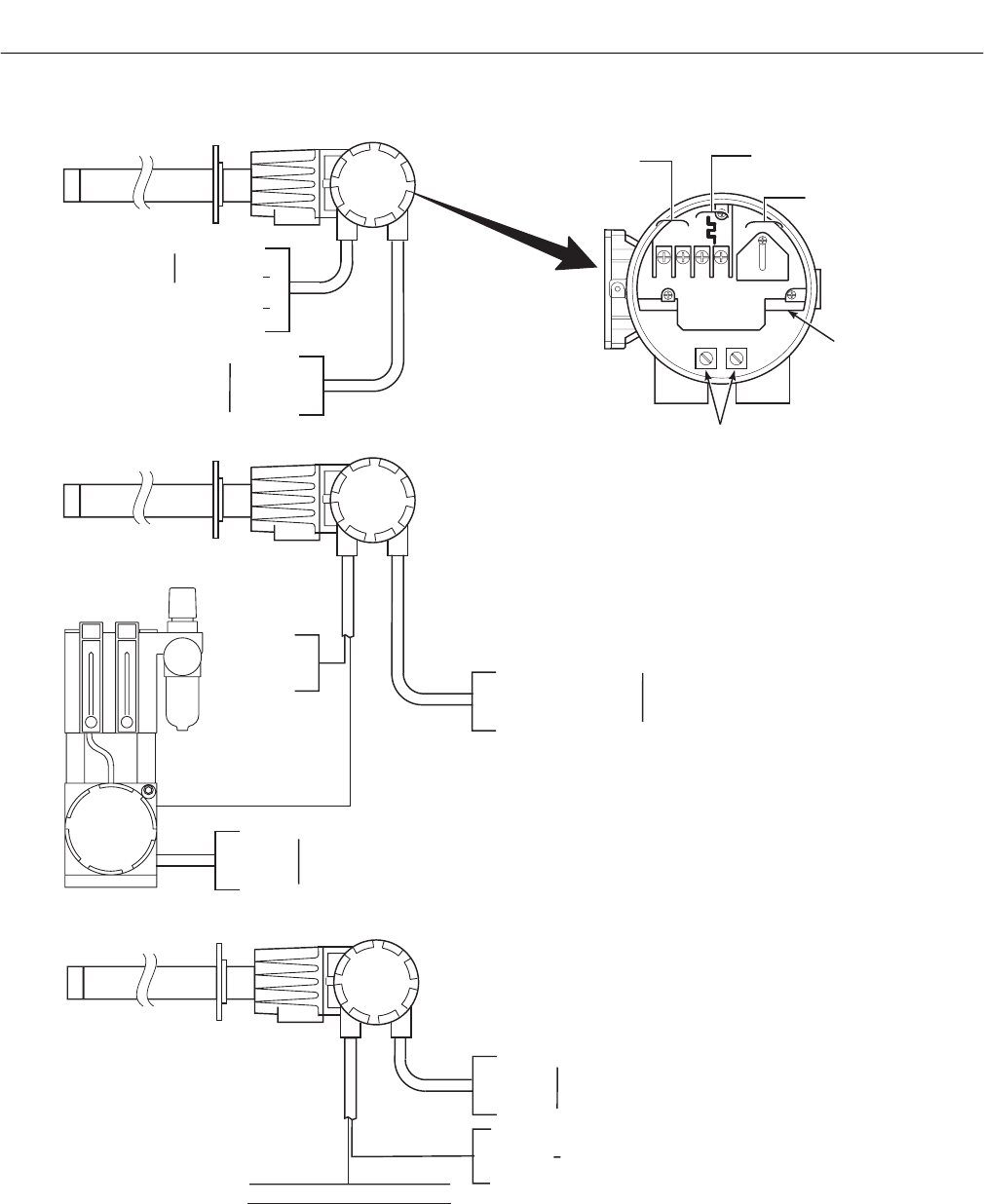
Instruction Manual
IB-106-340C Rev. 4.1
July 2004
2-10 Installation Rosemount Analytical Inc. A Division of Emerson Process Management
Hazardous Area Oxymitter 4000
INTEGRAL ELECTRONICS
WITHOUT SPS 4000
CALIBRATION
HANDSHAKE/
LOGIC I/O
LINE VOLTAGE
4-20 mA
SIGNAL
AC L1
AC N
+
+
-
-
4-20
LOGIC I/O +
LOGIC I/O -
4-20 mA +
4-20 mA -
GROUND
CALIBRATION
HANDSHAKE
LINE 1
NEUTRAL
GROUND
90-250 VAC, 50-60 HZ
LINE VOLTAGE INPUT
TERMINAL
BLOCK
GROUND
LUGS
CALIBRATION HANDSHAKE
REFER TO IMPS 4000
INSTRUCTION MANUAL
4 - 20mA +
4 - 20mA
GROUND
LINE 1
NEUTRAL
GROUND
90-250 VAC, 50-60 HZ
LINE VOLTAGE INPUT
INTEGRAL ELECTRONICS
WITH REMOTE SPS 4000
INTEGRAL ELECTRONICS
WITH REOMTE IMPS 4000
37270012
LINE 1
NEUTRAL
GROUND
90-250 VAC, 50-60 HZ
LINE VOLTAGE INPUT
CALIBRATION
HANDSHAKE
WALL-MOUNTED
SPS 4000
4-20 mA +
4-20 mA -
GROUND LINE 1
NEUTRAL
GROUND
90-250 VAC, 50-60 HZ
LINE VOLTAGE INPUT
Figure 2-9. Electrical Installation – Hazardous Area Oxymitter 4000 with Integral Electronics
Instruction Manual
IB-106-340C Rev. 4.1
July 2004
Rosemount Analytical Inc. A Division of Emerson Process Management Installation 2-11
Hazardous Area Oxymitter 4000
2-3 ELECTRICAL INSTALLATION (FOR
HAZARDOUS AREA OXYMITTER 4000
WITH REMOTE ELECTRONICS)
All wiring must conform to local and national
codes.
Disconnect and lock out power before
connecting the unit to the power
supply.
Install all protective equipment covers
and safety ground leads after installa-
tion. Failure to install covers and
ground leads could result in serious
injury or death.
To meet the Safety Requirements of
IEC 1010 (EC requirement), and ensure
safe operation of this equipment, con-
nection to the main electrical power
supply must be made through a circuit
breaker (min 10 A) which will discon-
nect all current-carrying conductors
during a fault situation. This circuit
breaker should also include a me-
chanically operated isolating switch. If
not, then another external means of
disconnecting the supply from the
equipment should be located close by.
Circuit breakers or switches must
comply with a recognized standard
such as IEC 947.
The probe and probe abrasive shield
are heavy. Use proper lifting and car-
rying procedures to avoid personnel
injury.
To maintain explosion-proof protec-
tion, all cable entry devices and
blanking elements for unused aper-
tures must be certified flameproof,
suitable for the conditions of use and
be properly installed.
a. Remove screw (18, Figure 9-4), cover lock
(19), captive washer (20), and left side blind
cover (17) from the remote electronics.
b. Connect Line Voltage. Connect the line, or
L1, wire to the L1 terminal and the neutral,
or L2 wire, to the N terminal (Figure 2-10).
The Hazardous Area Oxymitter 4000 will
automatically configure itself for 90-250
VAC line voltage and 50/60 Hz. To avoid a
shock hazard, the power terminal cover
must be installed.
c. Connect 4-20 mA Signal and Calibration
Handshake/Logic I/O Leads (Figure 2-10).
1. 4-20 mA Signal. The 4-20 mA signal
represents the O2 value and can also
operate the Model 751 Loop LCD Dis-
play or any other loop powered display.
Superimposed on the 4-20 mA signal is
HART information that is accessible
through a Model 275/375 Handheld
Communicator or AMS software.
2
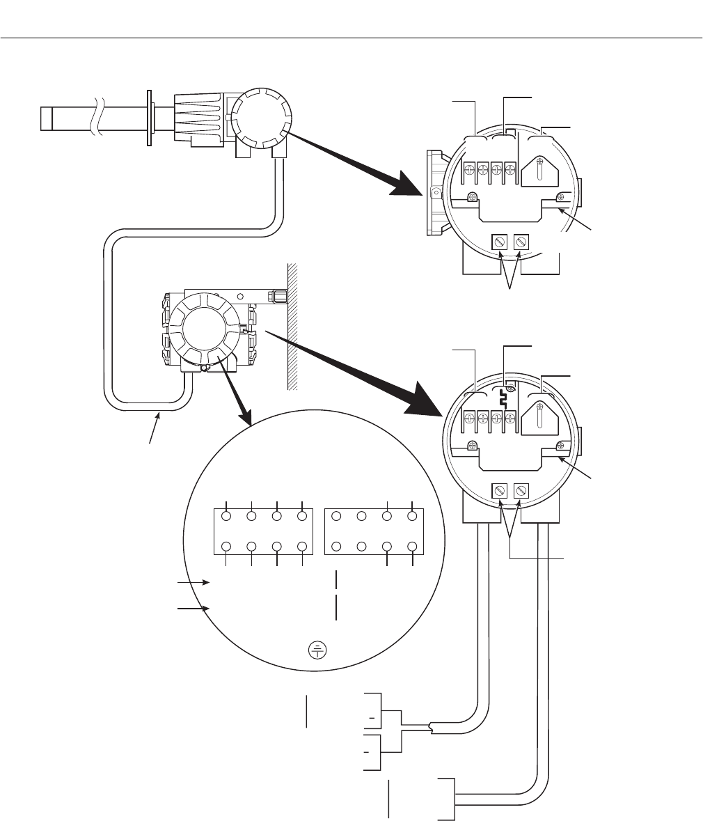
Instruction Manual
IB-106-340C Rev. 4.1
July 2004
2-12 Installation Rosemount Analytical Inc. A Division of Emerson Process Management
Hazardous Area Oxymitter 4000
TYPE K
THERMOCOUPLE
SIGNAL
HEATER POWER
(BELOW COVER)
OXYGEN
SIGNAL
+
+
-
-
TERMINAL
BLOCK
GROUND
LUGS
37270023
LINE VOLTAGE
4-20 mA
SIGNAL
AC L1
AC N
+
+
-
-
4-20
TERMINAL
BLOCK
GROUND LUGS
1234
GRN
ORN
YEL
RED
BLK
BLK
ORN
RED
BLK
HTR
T/C
O
CELL
2
WIRING DIAGRAM
TO ELECTRONICS
FROM PROBE
WHT
BRN
GRN
RED
BRN
BLU
CALIBRATION
HANDSHAKE/
LOGIC I/O
PROBE
REMOTE
ELECTRONICS
TO IMPS 4000 IF USED.
REFER TO IMPS 4000
INSTRUCTION MANUAL.
LOGIC I/O +
LOGIC I/O -
LINE 1
NEUTRAL
GROUND
90-250 VAC, 50-60 HZ
LINE VOLTAGE INPUT
INTERCONNECTING
CABLE
4-20 mA +
4-20 mA -
GROUND
5678
(WHT)
(RED)
(BLU)
(HAZ.)
(BRN)
(GRN)
(BRN)
BLU
YEL
WHT
GRN/YEL
or GRN
G.P.
HAZARDOUS AREA
OXYMITTER
GENERAL PURPOSE
OXYMITTER
Figure 2-10. Electrical Installation – Hazardous Area Oxymitter 4000
with Remote Electronics (Sheet 1 of 2)
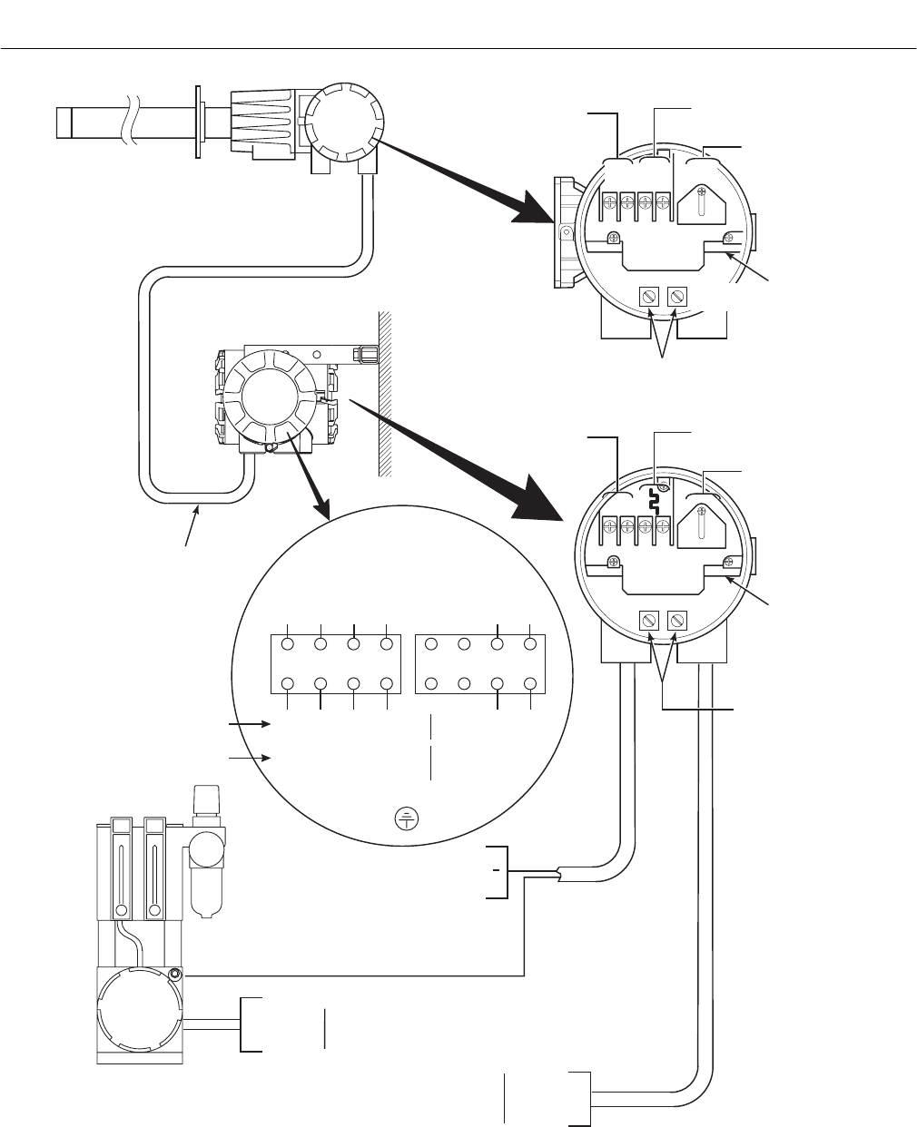
Instruction Manual
IB-106-340C Rev. 4.1
July 2004
Rosemount Analytical Inc. A Division of Emerson Process Management Installation 2-13
Hazardous Area Oxymitter 4000
TYPE K
THERMOCOUPLE
SIGNAL
HEATER POWER
(BELOW COVER)
OXYGEN
SIGNAL
+
+
-
-
LINE 1
NEUTRAL
GROUND
90-250 VAC, 50-60 HZ
LINE VOLTAGE INPUT
TERMINAL
BLOCK
GROUND
LUGS
37270024
LINE VOLTAGE
4-20 mA
SIGNAL
AC L1
AC N
+
+
-
-
4-20
TERMINAL
BLOCK
GROUND LUGS
4-20 mA +
4-20 mA
GROUND
LINE 1
NEUTRAL
GROUND
90-250 VAC, 50-60 HZ
LINE VOLTAGE INPUT
CALIBRATION
HANDSHAKE/
LOGIC I/O
CALIBRATION HANDSHAKE
WALL-MOUNTED
SPS 4000
PROBE
REMOTE
ELECTRONICS
INTERCONNECTING
CABLE
WHT
BRN
GRN
RED
BRN
BLU
GRN/YEL
or GRN
1234
GRN
ORN
YEL
RED
BLK
BLK
ORN
RED
BLK
HTR
T/C
O
CELL
2
WIRING DIAGRAM
TO ELECTRONICS
FROM PROBE
5678
(WHT)
(RED)
(BLU)
(HAZ.)
(BRN)
(GRN)
(BRN)
BLU
YEL
WHT
G.P.
HAZARDOUS AREA
OXYMITTER
GENERAL PURPOSE
OXYMITTER
Figure 2-10. Electrical Installation – Hazardous Area Oxymitter 4000
with Remote Electronics (Sheet 2 of 2)
2
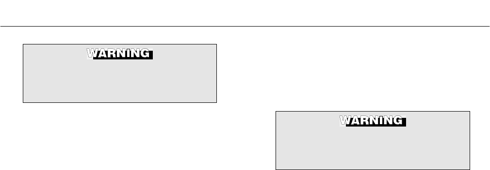
Instruction Manual
IB-106-340C Rev. 4.1
July 2004
2-14 Installation Rosemount Analytical Inc. A Division of Emerson Process Management
Hazardous Area Oxymitter 4000
If using an IMPS 4000 or an SPS 4000,
install it in a non-hazardous, explosive-
free environment.
2. Calibration Handshake/Logic I/O. The
output signal can be used to trigger an
alarm or to provide a calibration hand-
shake signal to an IMPS or SPS 4000.
If autocalibration is not utilized, a
common bi-directional logic contact is
provided for any of the equipment
alarms listed in Table 8-1. The assign-
ment of alarms that will actuate this
contact is modified by one of seven
additional configuration settings (mode
1 through mode 7) listed in Table 4-1.
The logic contact is self-powered,
+5 VDC, with a 340 ohm series resis-
tance. An interposing relay is required
if the logic contact will annunciate a
higher voltage device, such as a light
or horn. An interposing relay may also
be required for certain DCS input
cards. A Potter & Brumfield model
R10S-E1Y1-J1.0K 3.2 mA DC (or
equal) interposing relay will be
mounted where the contact wires
terminate in the control/relay room.
d. Install cover (17, Figure 9-4) and secure
with captive washer (20), cover lock (19),
and screw (18).
e. Install Interconnecting Cable
NOTE
If interconnect cable was not purchased
with the Hazardous Area Oxymitter
4000, consult the factory for the proper
wire type and gauge.
1. Remove cover (17, Figure 9-4) from
the junction box (24). Connect the
electronics end of the interconnecting
cable (30) to the “FROM PROBE” side
of the terminal block (Figure 2-10).
If using an IMPS 4000 or an SPS 4000,
install it in a non-hazardous, explosive-
free environment.
2. Loosen screw (18, Figure 9-3), cover
lock (19) and washer (20) at the probe
head. Remove cover (17).
3. See (Figure 2-10). Connect the heater
power leads, the thermocouple leads,
and the oxygen signal leads of the in-
terconnecting cable to the terminal
block. The cable leads are tagged for
polarity. To avoid a shock hazard, the
heater power terminal cover must be
installed.
4. Install covers (17, Figure 9-3 and
Figure 9-4) and secure with captive
washers (20), cover locks (19), and
screws (18).
2-4 PNEUMATIC INSTALLATION
a. Reference Air Package
After the Hazardous Area Oxymitter 4000 is
installed, connect the reference air set to
the Hazardous Area Oxymitter 4000. Refer
to Figure 2-11.
Instrument Air (Reference Air): 68.95 kPa
gage (10 psig) minimum, 1551.38 kPa gage
(225 psig) maximum at 0.5 scfm (0.25 l/hr)
maximum; less than 40 parts-per-million
total hydrocarbons. Regulator outlet pres-
sure should be set at 35 kPa (5 psi).
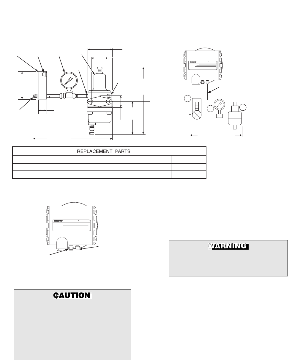
Instruction Manual
IB-106-340C Rev. 4.1
July 2004
Rosemount Analytical Inc. A Division of Emerson Process Management Installation 2-15
Hazardous Area Oxymitter 4000
37270008
REF AIR SET
263C152G01
1 FLOWMETER 0.006-0.057 SCMH (0.2-2.0 SCFH) 771B635H02
2 PRESSURE GAGE 0-103 KPA GAGE (0-15 PSIG) 275431-006
3 COMBINATION FILTER-REG. 0-207 KPA GAGE (0-30 PSIG) 4505C21G01
NOTE: DIMENSIONS ARE IN MILLIMETERS
WITH INCHES IN PARENTHESES. ALL
PIPING SPECIFIED IN U.S. STANDARDS.
1
23
122.17 (4.81)
FLOW SET
POINT KNOB
0.125-27 NPT
OUTLET
30.22
(1.19)
254
(10.0)
DRAIN
VALVE
79.25 ( MAX3.12)
215.90
(8.50)
MAX
50.80
(2.0)
MOUNTING
HOLES
81.03
()LG
FOR
7.92 ( )
DIA.
THROUGH
BOLTS
3.19
0.312
38.10
(1.50)
57.15 (2.250)
SCHEMATIC HOOKUP FOR REFERENCE
AIR SUPPLY TO HAZARDOUS AREA
OXYMITTER 4000 PROBE HEAD.
OUTLET 0.25-18
NPT
INLET
INSTRUMENT AIR
69-1551 KPA GAGE
(10-225 PSIG) MAX.
0.250 IN. OR 6 MM O.D. TUBING
(SUPPLIED BY CUSTOMER)
500 VA
SERIAL NO.
TAG NO.
OXYMITTER 4000
WATTS:VOLTS:
FUSE:LINEOUTPUT:
Rosemount Analytical Inc.
Orrville,OH 44667-0901
85-264 VAC 48-62 Hz
TM
800-433-6076
4-20 mA
R
5 Amps
TM
HART
SMART FAMILY
REF
23
1
Figure 2-11. Air Set, Plant Air Connection
500 VA
R
SERIAL NO.
TAG NO.
OXYMITTER 4000
VOLTS: WATTS:
OUTPUT: LINE FUSE:
Rosemount Analytical Inc.
Orrville,OH 44667-0901
85-264 VAC 48-62 Hz
TM
800-433-6076
4-20 mA
R
5 Amps
TM
HART
SMART FAMILY
CALIBRATION GAS
REFERENCE AIR
26170025
Figure 2-12. Hazardous Area Oxymitter 4000
Gas Connections
Do not use 100% nitrogen as a low gas
(zero gas). It is suggested that gas for
the low (zero) be between 0.4% and
2.0% O2. Do not use gases with hydro-
carbon concentrations of more than 40
parts per million. Failure to use proper
gases will result in erroneous
readings.
b. Calibration Gas
Two calibration gas concentrations are used
with the Hazardous Area Oxymitter 4000,
Low Gas - 0.4% O2 and High Gas - 8% O2.
See Figure 2-12 for the Hazardous Area
Oxymitter 4000 connections.
If using an IMPS 4000 or an SPS 4000,
install it in a non-hazardous, explosive-
free environment.
2-5 IMPS 4000 CONNECTIONS
Ensure the IMPS 4000 is installed in a safe
(non-hazardous, explosive-free) area and verify
the wiring and pneumatic connections per the
IMPS 4000 Intelligent Multi-probe Test Gas
Sequencer Instruction Bulletin.
2-6 SPS 4000 CONNECTIONS
Ensure the SPS 4000 is installed in a safe (non-
hazardous, explosive-free) area and verify the
wiring and pneumatic connections per the SPS
4000 Single Probe Autocalibration Sequencer
Instruction Bulletin.
2
Instruction Manual
IB-106-340C Rev. 4.1
July 2004
2-16 Installation Rosemount Analytical Inc. A Division of Emerson Process Management
Hazardous Area Oxymitter 4000
NOTE
!
Upon completing installation, make sure that the Hazardous Area Oxymitter
4000 is turned on and operating prior to firing up the combustion process.
Damage can result from having a cold Hazardous Area Oxymitter 4000 ex-
posed to the process gases.
During outages, and if possible, leave all Hazardous Area Oxymitter 4000
units running to prevent condensation and premature aging from thermal
cycling.
If the ducts will be washed down during outage, MAKE SURE to power down
the Hazardous Area Oxymitter 4000 units and remove them from the wash
area.
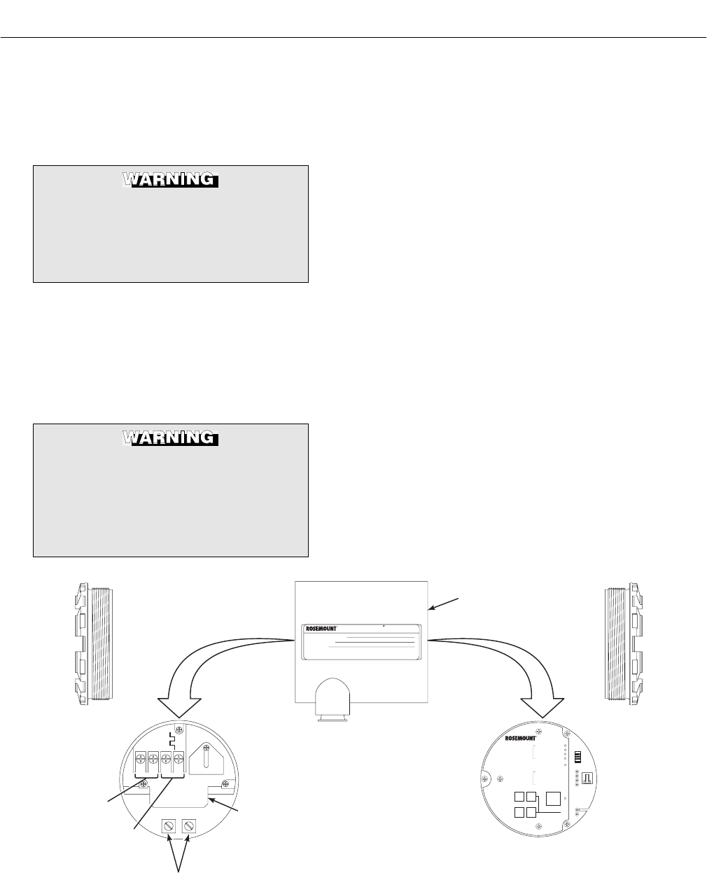
Instruction Manual
IB-106-340C Rev. 4.1
July 2004
Rosemount Analytical Inc. A Division of Emerson Process Management Configuration with Keypad 3-1
Hazardous Area Oxymitter 4000
SECTION 3
CONFIGURATION OF HAZARDOUS AREA
OXYMITTER 4000 WITH MEMBRANE KEYPAD
Install all protective equipment covers
and safety ground leads before
equipment startup. Failure to install
covers and ground leads could result
in serious injury or death.
3-1 GENERAL
a. Verify Mechanical Installation
Ensure the Hazardous Area Oxymitter 4000
is installed correctly. See Section 2,
INSTALLATION.
Opening the electronics housing in
hazardous areas may cause an explo-
sion causing severe injury, or death.
It may be required to get a hot work
permit from your company safety offi-
cer before you open the housing.
b. Verify Terminal Block Wiring
1. Remove screw (18, Figure 9-3 or
Figure 9-4), cover lock (19), and cap-
tive washer (20) that secure cover (17)
on left side of housing (11). Remove
the cover.
2. Check the terminal block wiring
(Figure 3-1). Be sure the power, the
4-20 mA signal, and the logic outputs
are properly connected and secure.
To avoid a shock hazard, the power
terminal cover must be installed.
For units with remote electronics,
check the terminal block wiring at the
probe and at the remote electronics
unit.
3. Install the cover (17, Figure 9-3 or
Figure 9-4) over terminal block (15)
and secure with captive washer (20),
cover lock (19), and screw (18).
AC L1
AC N
+
+
-
-
4-20
500 VA
SERIAL NO.
TAG NO.
OXYMITTER 4000
WATTS:VOLTS:
FUSE:LINEOUTPUT:
Rosemount Analytical Inc.
Orrville, OH 44667-0901
85-264 VAC 48-62 Hz
TM
800-433-6076
4-20 mA
R
5 Amps
TM
HART
SMART FAMILY
DIAGNOSTIC
ALARMS
TEST
POINTS
HEATER T/C
HEATER
02 CELL
CALIBRATION
CALIBRATION RECOMMENDED
02 CELL mV +
02 CELL mv -
HEATER T/C +
HEATER T/C -
INC INC
DEC DEC
HIGH
GAS
LOW
GAS
CAL
TEST GAS +
PROCESS -
% 02
SW2
TP1 J1
TP2
TP3
RED
YEL
GRN
ORG
TP4
TP5
TP6
ON
4-20 mA
SIGNAL
LOGIC I/O
GROUND LUGS
TERMINAL
BLOCK
HAZARDOUS AREA
OXYMITTER 4000
ELECTRONICS
HOUSING
37270002
Figure 3-1. Electronics Housing Terminals and Membrane Keypad
3
Instruction Manual
IB-106-340C Rev. 4.1
July 2004
3-2 Configuration with Keypad Rosemount Analytical Inc. A Division of Emerson Process Management
Hazardous Area Oxymitter 4000
c. Verify Hazardous Area Oxymitter 4000
Configuration
Located on the microprocessor board, the
top board, are two switches that configure
outputs for the Hazardous Area Oxymitter
4000 (Figure 3-2). SW1 determines if the
4-20 mA signal is internally or externally
powered. SW2 determines:
The HART option is not protected by
energy limiting barriers. It must not be
interfaced from within the hazardous
area. The 4-20 mA cables should be
routed and the connections made out-
side the hazardous area. Note that this
is the case even when using the intrin-
sically safe version of the handheld
communicator.
1. Hazardous Area Oxymitter 4000
status, HART or LOCAL.
2. Oxygen range, 0 to 10% O2 or 0 to
25% O2. (0 to 40% O2 is also configur-
able only through HART/AMS.)
3. The 4-20 mA signal, at fault or power
up, 3.5 mA or 21.6 mA.
Remove power from the Hazardous
Area Oxymitter 4000 before changing
defaults. If defaults are changed under
power, damage to the electronics
package may occur.
d. SW1
The two settings are internally or externally
powering the 4-20 mA signal. The factory
setting is for the 4-20 mA signal to be inter-
nally powered.
e. SW2
The factory sets this switch as follows:
1. Position 1 is HART/LOCAL. This switch
setting controls the configuration of the
Hazardous Area Oxymitter 4000. The
defaults cannot be changed via HART-
/AMS unless the switch is in the HART
position. Placing SW2, position 1 in the
LOCAL position forces the O2 range to
the setting of position 2. The position 1
switch must be placed in the LOCAL
position or changes in SW2, position 2
will have no effect.
2. Position 2 determines the O2 range.
This can be set to either 0 to 10% O2
or 0 to 25% O2. The factory setting is
0 to 10% O2.
Typically, the probe’s sensing cell, in
direct contact with the process gases,
is heated to approximately 736°C
(1357°F). The external temperature of
the probe body may exceed 450°C
(842°F). If operating conditions also
contain high oxygen levels and com-
bustible gases, the Hazardous Area
Oxymitter 4000 may self-ignite.
If necessary, the O2 range can be con-
figured from 0 to 40% O2. To select
values within this range, set SW2,
position 1 to HART and then enter the
range via HART/AMS. Do not change
SW2, position 1 to LOCAL unless you
want to operate in the range specified
by SW2, position 2.
3. Position 3 determines the output at
startup or at an alarm. The settings are
3.5 mA or 21.6 mA. The factory setting
is 3.5 mA. At startup, the current at the
analog output is 3.5 mA or 21.6 mA.
4. Position 4 can be used to set the
heater for 115 or 220 Vac operation.
This switch is functional only when the
software is set for manual voltage
selection (Auto Tune = No). Otherwise,
the internal electronics auto detect the
input line voltage and sets the heater
voltage accordingly (Auto Tune = Yes).
f. Once the cell is up to operating tempera-
ture, the O2 percentage can be read:
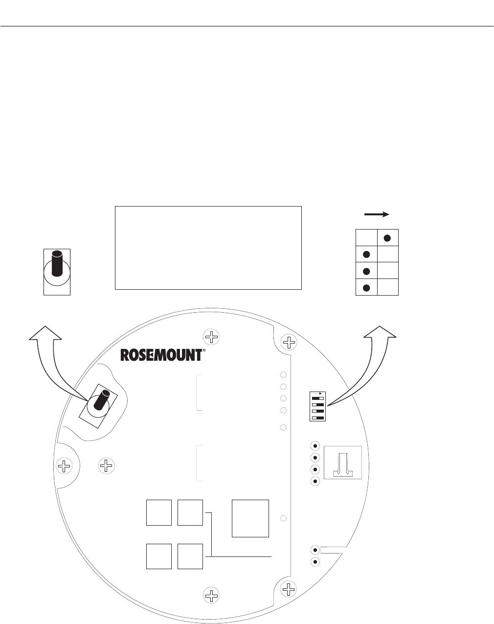
Instruction Manual
IB-106-340C Rev. 4.1
July 2004
Rosemount Analytical Inc. A Division of Emerson Process Management Configuration with Keypad 3-3
Hazardous Area Oxymitter 4000
1. Access TP5 and TP6 next to the mem-
brane keypad. Attach a multimeter
across TP5 and TP6. The calibration
and process gases can now be moni-
tored. Pressing the INC or DEC once
will cause the output to switch from the
process gas to the calibration gas.
Pressing INC or DEC a second time
will increase or decrease the calibra-
tion gas parameter. If the keys have
been inactive for one minute, the
output reverts to the process gas.
When a calibration has been initiated,
the value at TP5 and TP6 is the %O2
seen by the cell. Oxygen levels, as
seen on the multimeter, are:
8.0% O2 = 8.0 VDC
0.4% O2 = 0.4 VDC
2. HART/AMS.
3. Model 751. The loop-driven LCD
display.
DIAGNOSTIC
ALARMS
TEST
POINTS
HEATER T/C
HEATER
O2 CELL
CALIBRATION
CALIBRATION RECOMMENDED
O2 CELL mV +
O2 CELL mV -
HEATER T/C +
HEATER T/C -
INC INC
DEC DEC
HIGH
GAS
LOW
GAS
CAL
TEST GAS +
PROCESS -
% O2
SW2
SW1
TP1 J1
TP2
TP3
RED
YEL
GRN
ORG
TP4
TP5
TP6
ON
4-20 mA IS
INTERNALLY
POWERED (DEFAULT)
4-20 mA REQUIRES
EXTERNAL POWER
HART
0 TO 10% O2
3.5 mA
220 V 115 V
0 TO 25% O2
LOCAL
21.6 mA
DEFAULT
POSITION
(EX-FACTORY)
3.5 mA/21.6 mA:
0 TO 25% O :
2
0 TO 10% O /
2
LOCAL:
HART: O RANGE SET BY HART/AMS
(FROM 0 TO 40% O )
O RANGE SET BY POS 2
O RANGE
WHEN ALARM EXISTS, OR ON
POWER-UP, OUTPUT CURRENT
GOES TO THIS VALUE
2
2
2
2
1
2
3
4
37270001
ON
OFF
NOTE:
THE 115 V OPTION AT
SWITCH SW2 POSITION 4
IS ACTIVE ONLY WHEN
THE HEATER VOLTAGE
OPTION IS SET TO MANUAL
IN THE SOFTWARE
(AUTO TUNE = NO).
Figure 3-2. Defaults – Hazardous Area Oxymitter 4000 with Membrane Keypad
3

Instruction Manual
IB-106-340C Rev. 4.1
July 2004
3-4 Configuration with Keypad Rosemount Analytical Inc. A Division of Emerson Process Management
Hazardous Area Oxymitter 4000
The HART option is not protected by
energy limiting barriers. It must not be
interfaced from within the hazardous
area. The 4-20 mA cables should be
routed and the connections made out-
side the hazardous area. Note that this
is the case even when using the intrin-
sically safe version of the handheld
communicator.
3-2 LOGIC I/O
This two-terminal logic contact can be config-
ured either as a solid-state relay-activated alarm
or as a bi-directional calibration handshake sig-
nal to an IMPS 4000 or SPS 4000. The configu-
ration of this signal depends on the setting of
the LOGIC I/O PIN MODE via HART/AMS or
LOI. The ten different modes available are
explained in Table 3-1.
a. Alarm
When configured as an alarm, this signal
alerts you to an out-of-spec condition. The
output is +5 Vdc in series with a 340 ohm
resistor.
For optimum performance, Rosemount rec-
ommends connecting the output to a Potter
& Brumfield 3.2 mA DC relay (P/N R10S-
E1Y1-J1.0K).
Of the ten modes in Table 3-1, modes 0
through 7 are the alarm modes. The factory
default is mode 5 for Hazardous Area Oxy-
mitter 4000 units without an IMPS 4000 or
SPS 4000. In this mode, the output will sig-
nal when a unit alarm or a CALIBRATION
RECOMMENDED indication occurs.
b. Calibration Handshake Signal
If using an optional IMPS 4000 or SPS
4000, the logic I/O must be configured for
calibration handshaking. Of the ten modes
in Table 3-1, only modes 8 and 9 are con-
figured for calibration handshaking. For a
Hazardous Area Oxymitter 4000 with an
IMPS 4000 or an SPS 4000, the factory
sets the default to mode 8. In this mode,
the logic I/O will be used to communicate
between the Hazardous Area Oxymitter
4000 and the sequencer and to signal the
sequencer when a CALIBRATION REC-
OMMENDED indication occurs.
Table 3-1. Logic I/O Configuration (as set at HART/AMS or LOI)
Mode Configuration
0 The unit is not configured for any alarm condition.
1 The unit is configured for a Unit Alarm.
2 The unit is configured for Low O2.
3 The unit is configured for both a Unit Alarm and Low O2.
4 The unit is configured for a High AC Impedance/CALIBRATION
RECOMMENDED.
5* The unit is configured for both a Unit Alarm and a High AC Imped-
ance/CALIBRATION RECOMMENDED.
6The unit is configured for both a Low O2 and High AC Imped-
ance/CALIBRATION RECOMMENDED.
7 The unit is configured for a Unit Alarm, a Low O2, and a High AC Im-
pedance/CALIBRATION RECOMMENDED.
8** The unit is configured for a calibration handshake with IMPS 4000 or
SPS 4000. CALIBRATION RECOMMENDED will initiate the calibra-
tion cycle.
9 The unit is configured for a calibration handshake. CALIBRATION
RECOMMENDED will not initiate the calibration cycle with the IMPS
4000 or SPS 4000.
* The default condition for a Hazardous Area Oxymitter 4000 without an IMPS 4000 or SPS 4000.
** The default condition for a Hazardous Area Oxymitter 4000 with an IMPS 4000 or SPS 4000.

Instruction Manual
IB-106-340C Rev. 4.1
July 2004
Rosemount Analytical Inc. A Division of Emerson Process Management Configuration with Keypad 3-5
Hazardous Area Oxymitter 4000
3-3 RECOMMENDED CONFIGURATION
a. 4-20 mA Signal Upon Critical Alarm
Rosemount recommends that the factory
default be utilized. The 4-20 mA signal will
go to the 3.5 mA level upon any critical
alarm which will cause the O2 reading to be
unusable. Customer can also select 21.6
mA as the failure setting if normal opera-
tions cause O2 readings to go below the
zero % O2 (3.5 mA) level.
If the O2 measurement is being utilized as
part of an automatic control loop, the loop
should be placed into manual upon this
failure event or other appropriate action
should be taken.
b. Calibration
Rosemount recommends utilizing an auto-
calibration system, actuated by the “calibra-
tion recommended” diagnostic. New O2 cells
may operate for more than a year, but older
cells may require recalibration every few
weeks as they near the end of their life.
This strategy ensures that the O2 reading
is always accurate, and eliminates many
unnecessary calibrations based on calendar
days or weeks since previous calibration.
When utilizing the SPS 4000 or IMPS 4000,
consider wiring some or all associated
alarm contacts.
1. CALIBRATION INITIATE. Contact from
the control room to an SPS 4000 or
IMPS 4000 (one per probe) provides
the ability to manually initiate a calibra-
tion at any time from the control room.
Note that calibrations can also be
initiated from a HART handheld com-
municator, from Asset Management
Solutions software, or from the keypad
on the Hazardos Area Oxymitter 4000.
2. IN CALIBRATION. One contact per
probe provides notification to the con-
trol room that the “calibration recom-
mended” diagnostic has initiated an
automatic calibration through the SPS
4000 or IMPS 4000. If the O2 signal is
being utilized in an automatic control
loop, this contact should be utilized
to place the control loop into manual
during calibration.
3. CALIBRATION FAILED. One contact
per probe from an SPS 4000 or IMPS
4000 to the control room for notification
that the calibration procedure failed.
Grouped with this alarm is an output
from a pressure switch which indicates
when the calibration gas bottles are
empty.
4. 4-20 mA SIGNAL DURING
CALIBRATION. The 4-20 mA signal
can be configured to respond normally
during any calibration, or it can be con-
figured to hold the last O2 value upon
the initiation of calibration. The factory
default is for the 4-20 mA signal to
track (operate normally) throughout
calibration. Holding the last O2 value
may be useful if several probes are
being averaged for the purpose of
automatic control. Unless several
probes are being averaged, always
place control loops that are using the
O2 signal into the manual mode prior to
starting the calibration.
3

Instruction Manual
IB-106-340C Rev. 4.1
July 2004
3-6 Configuration with Keypad Rosemount Analytical Inc. A Division of Emerson Process Management
Hazardous Area Oxymitter 4000
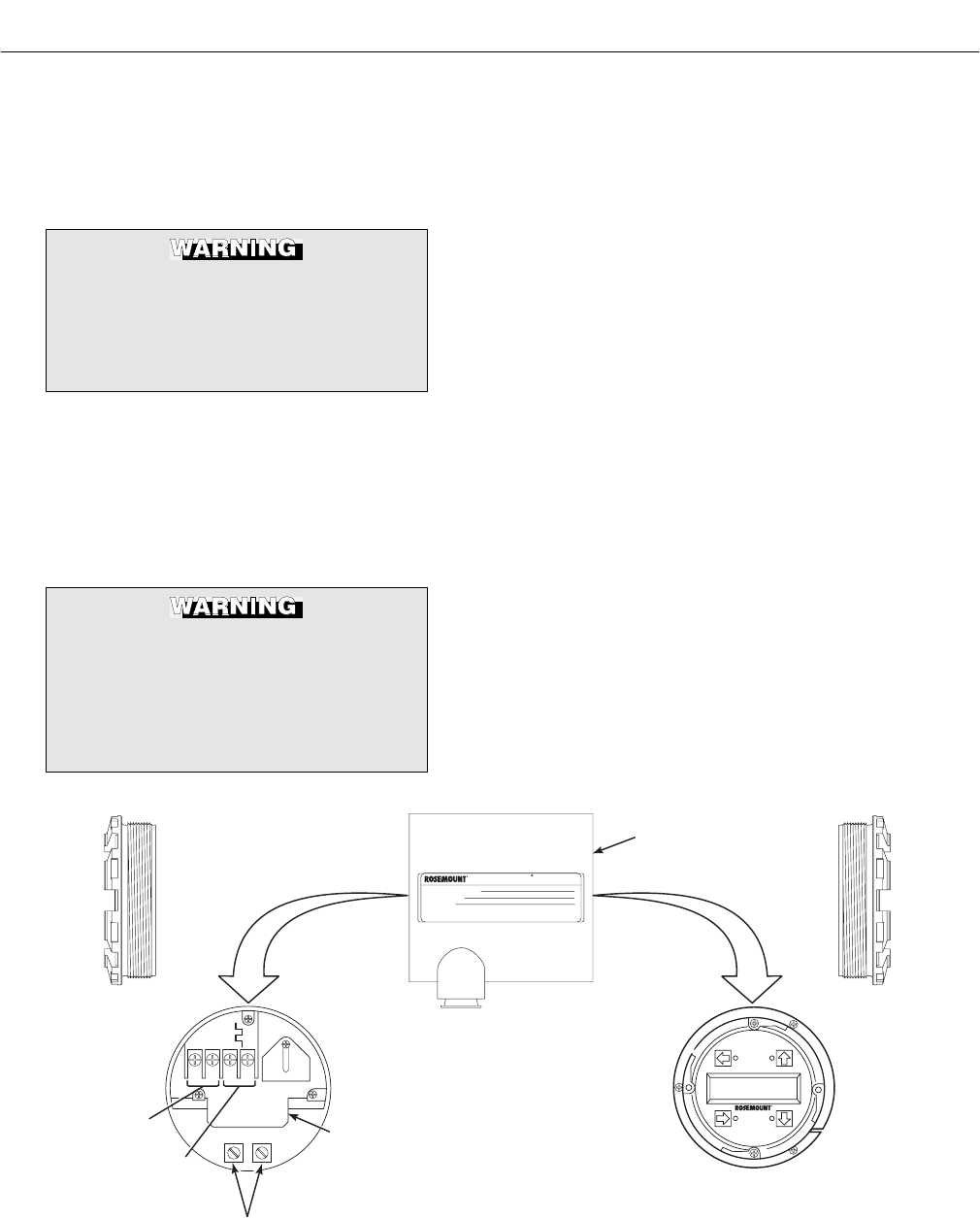
Instruction Manual
IB-106-340C Rev. 4.1
July 2004
Rosemount Analytical Inc. A Division of Emerson Process Management Configuration with LOI 4-1
Hazardous Area Oxymitter 4000
SECTION 4
CONFIGURATION OF HAZARDOUS AREA
OXYMITTER 4000 WITH LOI
Install all protective equipment covers
and safety ground leads before
equipment startup. Failure to install
covers and ground leads could result
in serious injury or death.
4-1 GENERAL
a. Verify Mechanical Installation
Ensure the Hazardous Area Oxymitter 4000
is installed correctly. See Section 2,
INSTALLATION.
Opening the electronics housing in
hazardous areas may cause an explo-
sion causing severe injury, or death.
It may be required to get a hot work
permit from your company safety offi-
cer before you open the housing.
b. Verify Terminal Block Wiring
1. Remove screw (18, Figure 9-3 or
Figure 9-4), cover lock (19), and cap-
tive washer (20) that secure cover (17)
on left side of housing (11). Remove
the cover to expose the terminal block
(15).
2. Check the terminal block wiring
(Figure 3-1). Be sure the power, the
4-20 mA signal, and the logic outputs
are properly connected and secure.
To avoid a shock hazard, the power
terminal cover must be installed.
For units with remote electronics,
check the terminal block wiring at the
probe and at the remote electronics
unit.
3. Install the cover (17, Figure 9-3 or
Figure 9-4) over terminal block (15)
and secure with captive washer (20),
cover lock (19), and screw (18).
AC L1
AC N
+
+
-
-
4-20
500 VA
SERIAL NO.
TAG NO.
OXYMITTER 4000
WATTS:VOLTS:
FUSE:LINEOUTPUT:
Rosemount Analytical Inc.
Orrville, OH 44667-0901
85-264 VAC 48-62 Hz
TM
800-433-6076
4-20 mA
R
5 Amps
TM
HART
SMART FAMILY
4-20 mA
SIGNAL
LOGIC I/O
GROUND LUGS
TERMINAL
BLOCK
HAZARDOUS AREA
OXYMITTER 4000
ELECTRONICS
HOUSING
37270010
LOI
Figure 4-1. Electronics Housing Terminals with LOI
4
Instruction Manual
IB-106-340C Rev. 4.1
July 2004
4-2 Configuration with LOI Rosemount Analytical Inc. A Division of Emerson Process Management
Hazardous Area Oxymitter 4000
c. Verify Hazardous Area Oxymitter 4000
Configuration
Located on the microprocessor board are
two switches that configure Hazardous
Area Oxymitter 4000 outputs (Figure 4-2).
To access these switches, the LOI module
must be removed. SW1 determines if the
4-20 mA signal is internally or externally
powered. SW2 determines:
The HART option is not protected by
energy limiting barriers. It must not be
interfaced from within the hazardous
area. The 4-20 mA cables should be
routed and the connections made out-
side the hazardous area. Note that this
is the case even when using the intrin-
sically safe version of the handheld
communicator.
1. Hazardous Area Oxymitter 4000
status, HART or LOCAL.
2. Oxygen range, 0 to 10% O2 or 0 to
25% O2. (0 to 40% O2 is also configur-
able only through HART/AMS.)
3. The 4-20 mA signal, at fault or power
up, 3.5 mA or 21.6 mA.
Remove power from the Hazardous
Area Oxymitter 4000 before changing
defaults. If defaults are changed under
power, damage to the electronics
package may occur.
d. SW1
The two settings are internally or externally
powering the 4-20 mA signal. The factory
setting is for the 4-20 mA signal to be inter-
nally powered.
e. SW2
The factory sets this switch as follows:
1. Position 1 is HART/LOCAL. This switch
setting controls the configuration of the
Hazardous Area Oxymitter 4000. The
defaults cannot be changed via
HART/AMS or the LOI unless the
switch is in the HART position. Placing
SW2, position 1 in the LOCAL position
forces the O2 range to the setting of
position 2. The position 1 switch must
be in the LOCAL position or changes in
SW2, position 2 will have no effect.
2. Position 2 determines the O2 range.
This can be set to either 0 to 10% O2
or 0 to 25% O2. The factory setting is
0 to 10% O2.
Typically, the probe’s sensing cell, in
direct contact with the process gases,
is heated to approximately 736°C
(1357°F). The external temperature of
the probe body may exceed 450°C
(842°F). If operating conditions also
contain high oxygen levels and com-
bustible gases, the Hazardous Area
Oxymitter 4000 may self-ignite.
If necessary, the O2 range can be con-
figured from 0 to 40% O2. To select
values within this range, set SW2,
position 1 to HART and then enter the
range via HART/AMS or the LOI. Do
not change SW2, position 1 to LOCAL
unless you want to operate in the
range specified by SW2, position 2.
3. Position 3 determines the output at
startup or at an alarm. The settings are
3.5 mA or 21.6 mA. The factory setting
is 3.5 mA. At startup, the current at the
analog output is 3.5 mA or 21.6 mA.
4. Position 4 can be used to set the
heater for 115 or 220 Vac operation.
This switch is functional only when the
software is set for manual voltage
selection (Auto Tune = No). Otherwise,
the internal electronics auto detect the
input line voltage and sets the heater
voltage accordingly (Auto Tune = Yes).
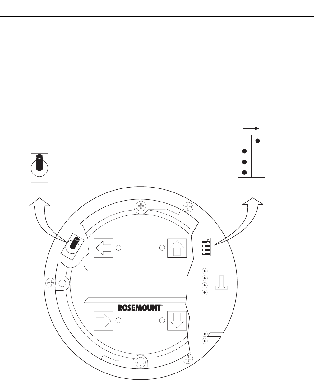
Instruction Manual
IB-106-340C Rev. 4.1
July 2004
Rosemount Analytical Inc. A Division of Emerson Process Management Configuration with LOI 4-3
Hazardous Area Oxymitter 4000
f. Once the cell is up to operating tempera-
ture, the O2 percentage can be read:
1. To access TP5 and TP6 under the LOI
module (Figure 4-2), power down the
Oxymitter 4000 and remove the LOI
module. Attach alligator leads from a
multimeter across TP5 and TP6
(Figure 3-2). Install the LOI module and
power up the Oxymitter 4000. Allow
time for the cell to reach operating
temperature. The calibration and proc-
ess gases can now be monitored.
When a calibration has been initiated,
the value at TP5 and TP6 is the % O2
seen by the cell. Oxygen levels, as
seen on the multimeter, are:
8.0% O2 = 8.0 VDC
0.4% O2 = 0.4 VDC
2. HART/AMS.
3. Model 751. The loop-driven LCD
display.
SW2
SW1
1
2
3
4
TP1 J1
TP2
TP3
RED
YEL
GRN
ORG
TP4
TP5
TP6
4-20 mA
IS INTERNALLY
POWERED
(DEFAULT)
4-20 mA REQUIRES
EXTERNAL POWER
HART
0 TO 10% O2
3.5 mA
220 V 115 V
0 TO 25% O2
LOCAL
21.6 mA
DEFAULT
POSITION
(EX-FACTORY)
3.5 mA/21.6 mA:
0 TO 25% O :
2
0 TO 10% O /
2
LOCAL:
HART: O RANGE SET BY HART/AMS
(FROM 0 TO 40% O )
O RANGE SET BY POS 2
O RANGE
WHEN ALARM EXISTS, OR
ON POWER UP, CURRENT
OUTPUT GOES TO THIS VALUE
2
2
2
2
37270011
ON
OFF
NOTE:
THE 115 V OPTION
AT SWITCH SW2
POSITION 4 IS ACTIVE
ONLY WHEN THE
HEATER VOLTAGE
OPTION IS SET TO
MANUAL IN THE
SOFTWARE.
Figure 4-2. Defaults – Hazardous Area Oxymitter 4000 with LOI
4
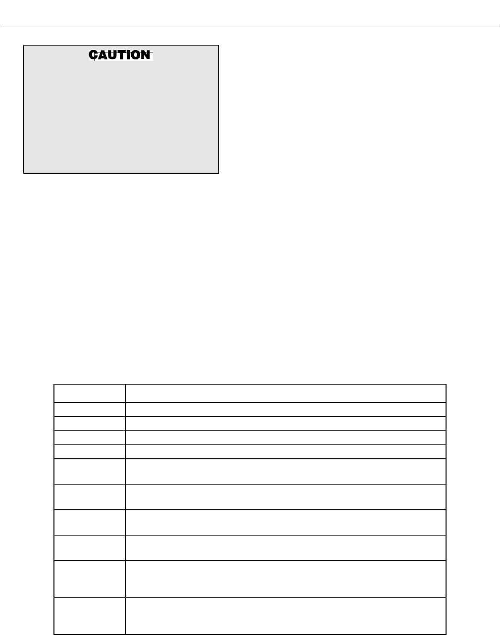
Instruction Manual
IB-106-340C Rev. 4.1
July 2004
4-4 Configuration with LOI Rosemount Analytical Inc. A Division of Emerson Process Management
Hazardous Area Oxymitter 4000
The HART option is not protected by
energy limiting barriers. It must not be
interfaced from within the hazardous
area. The 4-20 mA cables should be
routed and the connections made out-
side the hazardous area. Note that this
is the case even when using the intrin-
sically safe version of the handheld
communicator.
4-2 LOGIC I/O
This two-terminal logic contact can be config-
ured either as a solid-state relay-activated alarm
or as a bi-directional calibration handshake sig-
nal to an IMPS 4000 or SPS 4000. The configu-
ration of this signal depends on the setting of
the LOGIC I/O PIN MODE via HART/AMS or
LOI. The ten different modes available are
explained in Table 4-1.
a. Alarm
When configured as an alarm, this signal
alerts you to an out-of-spec condition. The
output is +5 Vdc in series with a 340 ohm
resistor.
For optimum performance, Rosemount rec-
ommends connecting the output to a Potter
& Brumfield 3.2 mA DC relay (P/N R10S-
E1Y1-J1.0K).
Of the ten modes in Table 4-1, mode 1
through mode 7 are the alarm modes. The
factory default is mode 5 for Hazardous
Area Oxymitter 4000 units without an IMPS
4000 or SPS 4000. In this mode, the output
will signal when a unit alarm or a CALIBRA-
TION RECOMMENDED indication occurs.
b. Calibration Handshake Signal
If using an optional IMPS 4000 or SPS
4000, the logic I/O must be configured for
calibration handshaking. Of the ten modes
in Table 4-1, only modes 8 and 9 are con-
figured for calibration handshaking. For a
Hazardous Area Oxymitter 4000 with an
IMPS 4000 or an SPS 4000, the factory
sets the default to mode 8. In this mode,
the logic I/O will be used to communicate
between the Hazardous Area Oxymitter
4000 and the sequencer and to signal the
sequencer when a CALIBRATION REC-
OMMENDED indication occurs.
Table 4-1. Logic I/O Configuration (as set at HART/AMS or LOI)
Mode Configuration
0 The unit is not configured for any alarm condition.
1 The unit is configured for a Unit Alarm.
2 The unit is configured for Low O2.
3 The unit is configured for both a Unit Alarm and Low O2.
4 The unit is configured for a High AC Impedance/CALIBRATION
RECOMMENDED.
5* The unit is configured for both a Unit Alarm and a High AC Imped-
ance/CALIBRATION RECOMMENDED.
6The unit is configured for both a Low O2 and High AC Imped-
ance/CALIBRATION RECOMMENDED.
7 The unit is configured for a Unit Alarm, a Low O2, and a High AC Im-
pedance/CALIBRATION RECOMMENDED.
8** The unit is configured for a calibration handshake with IMPS 4000 or
SPS 4000. CALIBRATION RECOMMENDED will initiate the calibra-
tion cycle.
9 The unit is configured for a calibration handshake. CALIBRATION
RECOMMENDED will not initiate the calibration cycle with the IMPS
4000 or SPS 4000.
* The default condition for a Hazardous Area Oxymitter 4000 without an IMPS 4000 or SPS 4000.
** The default condition for a Hazardous Area Oxymitter 4000 with an IMPS 4000 or SPS 4000.

Instruction Manual
IB-106-340C Rev. 4.1
July 2004
Rosemount Analytical Inc. A Division of Emerson Process Management Configuration with LOI 4-5
Hazardous Area Oxymitter 4000
4-3 RECOMMENDED CONFIGURATION
a. 4-20 mA Signal Upon Critical Alarm
Rosemount recommends that the factory
default be utilized. The 4-20 mA signal will
go to the 3.5 mA level upon any critical
alarm which will cause the O2 reading to be
unusable. Customer can also select 21.6
mA as the failure setting if normal opera-
tions cause O2 readings to go below the
zero % O2 (3.5 mA) level.
If the O2 measurement is being utilized as
part of an automatic control loop, the loop
should be placed into manual upon this
failure event or other appropriate action
should be taken.
b. Calibration
Rosemount recommends utilizing an auto-
calibration system, actuated by the “calibra-
tion recommended” diagnostic. New O2 cells
may operate for more than a year, but older
cells may require recalibration every few
weeks as they near the end of their life.
This strategy ensures that the O2 reading
is always accurate, and eliminates many
unnecessary calibrations based on calendar
days or weeks since previous calibration.
When utilizing the SPS 4000 or IMPS 4000,
consider wiring some or all associated
alarm contacts.
1. CALIBRATION INITIATE. Contact from
the control room to an SPS 4000 or
IMPS 4000 (one per probe) provides
the ability to manually initiate a calibra-
tion at any time from the control room.
Note that calibrations can also be
initiated from a HART handheld com-
municator, from Asset Management
Solutions software, or from the keypad
on the Oxymitter 4000.
2. IN CALIBRATION. One contact per
probe provides notification to the con-
trol room that the “calibration recom-
mended” diagnostic has initiated an
automatic calibration through the SPS
4000 or IMPS 4000. If the O2 signal is
being utilized in an automatic control
loop, this contact should be utilized
to place the control loop into manual
during calibration.
3. CALIBRATION FAILED. One contact
per probe from an SPS 4000 or IMPS
4000 to the control room for notification
that the calibration procedure failed.
Grouped with this alarm is an output
from a pressure switch which indicates
when the calibration gas bottles are
empty.
4. 4-20 mA SIGNAL DURING
CALIBRATION. The 4-20 mA signal
can be configured to respond normally
during any calibration, or it can be con-
figured to hold the last O2 value upon
the initiation of calibration. The factory
default is for the 4-20 mA signal to
track (operate normally) throughout
calibration. Holding the last O2 value
may be useful if several probes are
being averaged for the purpose of
automatic control. Unless several
probes are being averaged, always
place control loops that are using the
O2 signal into the manual mode prior to
starting the calibration.
4

Instruction Manual
IB-106-340C Rev. 4.1
July 2004
4-6 Configuration with LOI Rosemount Analytical Inc. A Division of Emerson Process Management
Hazardous Area Oxymitter 4000
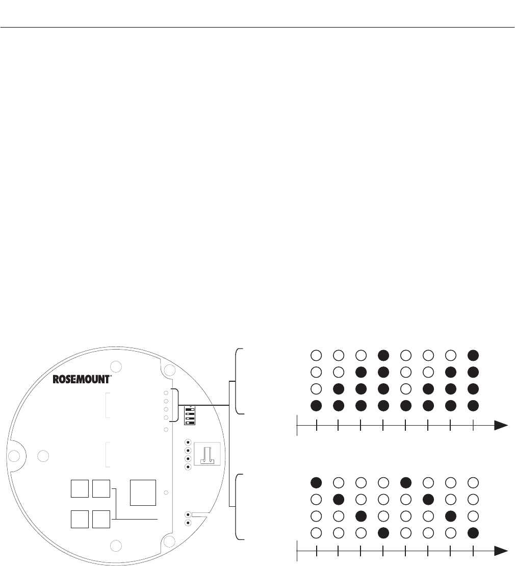
Instruction Manual
IB-106-340C Rev. 4.1
July 2004
Rosemount Analytical Inc. A Division of Emerson Process Management Startup and Operation with Keypad 5-1
Hazardous Area Oxymitter 4000
SECTION 5
STARTUP AND OPERATION
OF HAZARDOUS AREA OXYMITTER 4000
WITH MEMBRANE KEYPAD
5-1 POWER UP
a. Startup Display
When power is applied to the probe, the cell
heater turns on. It takes approximately one
half hour for the cell to heat to operating
temperature. This condition is indicated by
the top four LEDs (DIAGNOSTIC ALARMS)
on the membrane keypad (Figure 5-1).
Starting with the CALIBRATION LED, the
LEDs light in ascending order until all four
LEDs are on. At this point, all four turn off
and the cycle starts again. This ramp cycle
continues until the cell is up to operating
temperature.
b. Operating Display
The ramp cycle turns into a cycle where the
diagnostic LEDs light in sequence from the
top to the bottom, one at a time. After the
bottom LED turns on, the sequence starts
again at the top with the HEATER T/C LED
(Figure 5-1).
c. Error
If there is an error condition at startup, one
of the diagnostics LEDs will be blinking.
Refer to Section 8 TROUBLESHOOTING,
to determine the cause of the error. Clear
the error, cycle power, and the operating
display should return.
DIAGNOSTIC
ALARMS
TEST
POINTS
HEATER T/C
HEATER
O2 CELL
CALIBRATION
CALIBRATION RECOMMENDED
O2 CELL mV +
O2 CELL mv -
HEATER T/C +
HEATER T/C -
INC INC
DEC DEC
HIGH
GAS
LOW
GAS
CAL
TEST GAS +
PROCESS -
% O2
SW2
TP1 J1
TP2
TP3
RED
YEL
GRN
ORG
TP4
TP5
TP6
ON
HEATER T/C
HEATER
O CELL
2
CALIBRATION
LIGHTING SEQUENCE DURING NORMAL OPERATION
(OPERATING DISPLAY)
12 3 4 1 2 3 4
HEATER T/C
HEATER
O CELL
2
CALIBRATION
LIGHTING SEQUENCE DURING WARM-UP
(STARTUP DISPLAY)
12 3 4 1 2 3 4
22220056
Figure 5-1. Startup and Normal Operation
5
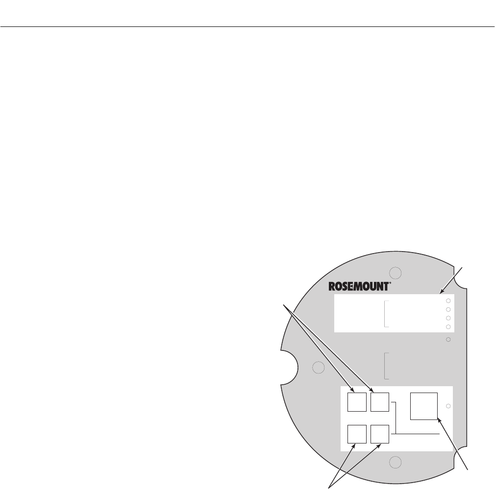
Instruction Manual
IB-106-340C Rev. 4.1
July 2004
5-2 Startup and Operation with Keypad Rosemount Analytical Inc. A Division of Emerson Process Management
Hazardous Area Oxymitter 4000
d. Keypad
The five membrane keys on the membrane
keypad are only used during calibration to
adjust the high and low gas and to initiate
the calibration sequence (Figure 5-2).
e. Reference Air
Ensure reference air, if used, is set to 56.6
l/hr (2 scfh).
5-2 OPERATION
a. Overview
Ensure the Hazardous Area Oxymitter 4000
is at normal operation. The diagnostic LEDs
will display the operating cycle. All other
LEDs should be off (See Figure 5-3).
1. DIAGNOSTIC ALARM LEDS. If there
is an error in the system, one of these
LEDs will flash various blink codes
(see Section 8, TROUBLESHOOT-
ING). In the case of multiple errors,
only one will be displayed based on a
priority system. Correct the problem
and cycle power. The operating display
will return or the next error will be dis-
played. The alarms are:
HEATER T/C
HEATER
O2 CELL
CALIBRATION
2. CALIBRATION RECOMMENDED
LED. Turns on when the system
determines that a calibration is recom-
mended. Further information is avail-
able in Section 9, MAINTENANCE
AND SERVICE.
3. TEST POINTS. Test points 1 through 6
allow you to monitor with a multimeter:
the heater thermocouple, the O2 cell
millivolt value, and the process O2.
(a) TP1 and TP2 monitor the oxygen
cell millivolt output, which equates
to the percentage of oxygen
present.
(b) TP3 and TP4 monitor the heater
thermocouple.
(c) TP5 and TP6 monitor the process
gas or the calibration gas
parameter.
DIAGNOSTIC
ALARMS
TEST
POINTS
HEATER T/C
HEATER
02 CELL
CALIBRATION
CALIBRATION RECOMMENDED
02 CELL mV +
02 CELL mv -
HEATER T/C +
HEATER T/C -
INC INC
DEC DEC
HIGH
GAS
LOW
GAS
CAL
TEST GAS +
PROCESS -
% 02
MEMBRANE
KEYS
MEMBRANE
KEYS
MEMBRANE
KEY
DIAGNOSTIC
LEDS
22220023
Figure 5-2. Calibration Keys
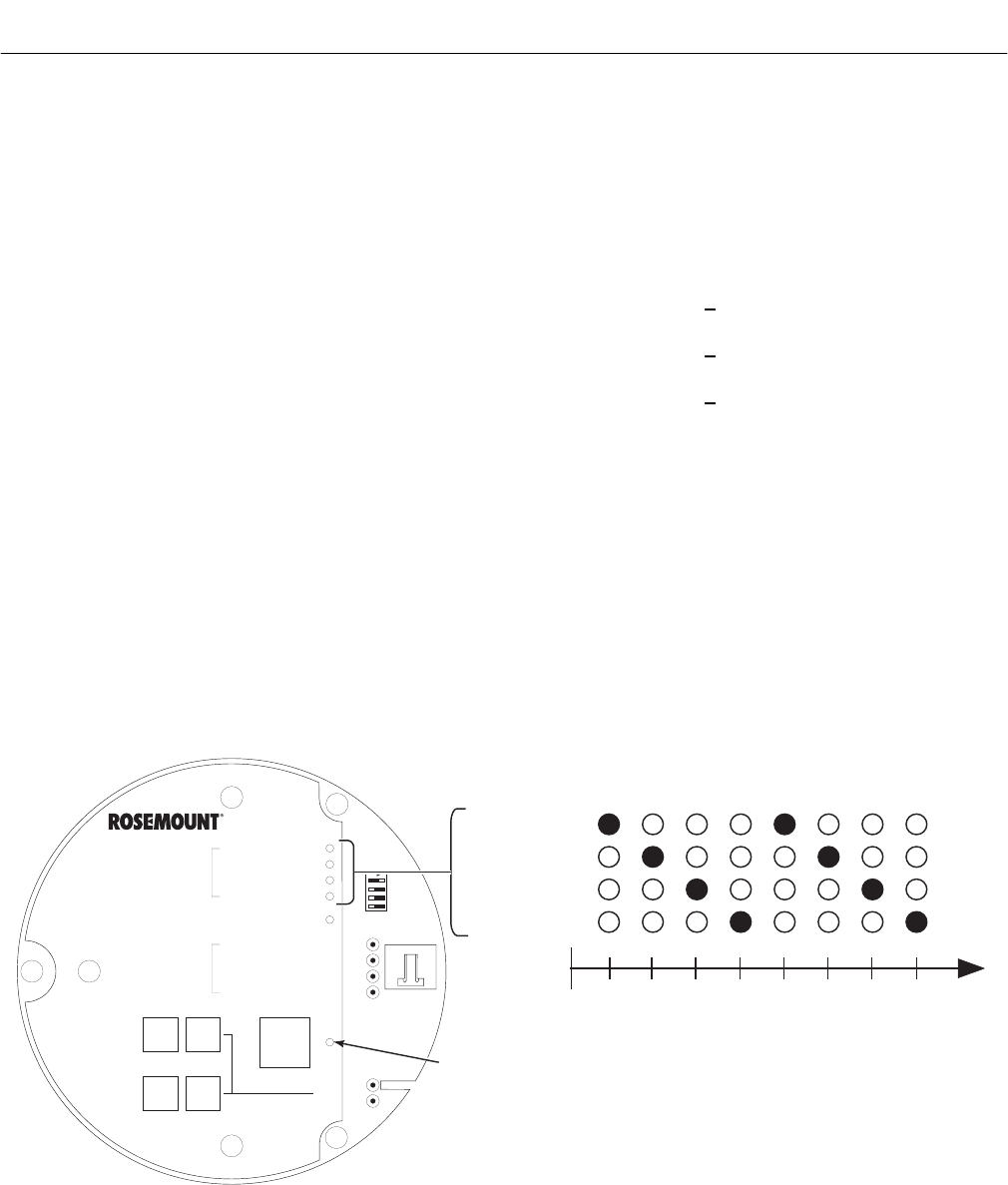
Instruction Manual
IB-106-340C Rev. 4.1
July 2004
Rosemount Analytical Inc. A Division of Emerson Process Management Startup and Operation with Keypad 5-3
Hazardous Area Oxymitter 4000
4. CAL LED. The CAL LED is on steady
or flashing during calibration. Further
information is available in Section 9,
MAINTENANCE AND SERVICE.
5. Keys.
(a) INC and DEC. The INC and DEC
keys are used to set the values of
the calibration gases. Attach a
multimeter across TP5 and TP6.
The calibration and process gases
can now be monitored. Pressing
the INC or DEC once will cause
the output to switch from the proc-
ess gas to the calibration gas.
Pressing INC or DEC a second
time will increase or decrease the
calibration gas parameter. If the
keys have been inactive for one
minute, the output reverts to the
process gas. When a calibration
has been initiated, the value at
TP5 and TP6 is the % O2 seen by
the cell.
Oxygen levels, as seen on the
multimeter, are:
8.0% O2 = 8.0 volts DC
0.4% O2 = 0.4 volts DC
(b) CAL. The CAL key can:
1 Initiate a calibration.
2 Sequence through calibration.
3 Abort the calibration.
NOTE
Refer to Section 9, MAINTENANCE AND
SERVICE, for calibration instructions.
b. Model 751 Remote Powered Loop
LCD Display (Optional)
Refer to Remote Powered Loop LCD
manual for calibration and operation.
HEATER T/C
HEATER
O CELL
2
CALIBRATION
LIGHTING SEQUENCE DURING NORMAL OPERATION
12 3 4 1 2 3 4
DIAGNOSTIC
ALARMS
TEST
POINTS
HEATER T/C
HEATER
O2 CELL
CALIBRATION
CALIBRATION RECOMMENDED
O2 CELL mV +
O2 CELL mv -
HEATER T/C +
HEATER T/C -
INC INC
DEC DEC
HIGH
GAS
LOW
GAS
CAL
TEST GAS +
PROCESS -
% O2
SW2
TP1 J1
TP2
TP3
RED
YEL
GRN
ORG
TP4
TP5
TP6
ON
CAL LED
22220055
Figure 5-3. Normal Operation
5

Instruction Manual
IB-106-340C Rev. 4.1
July 2004
5-4 Startup and Operation with Keypad Rosemount Analytical Inc. A Division of Emerson Process Management
Hazardous Area Oxymitter 4000
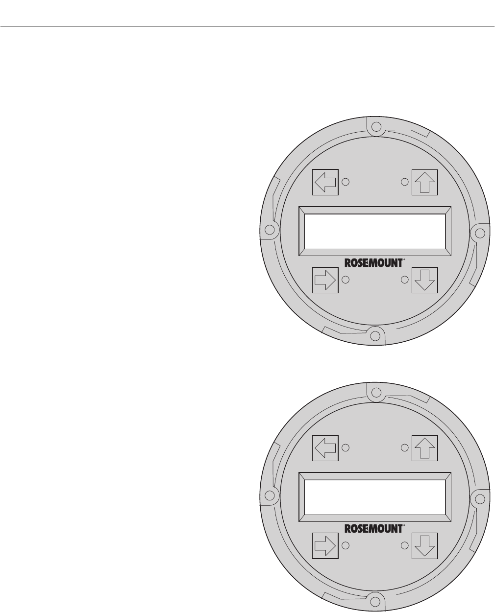
Instruction Manual
IB-106-340C Rev. 4.1
July 2004
Rosemount Analytical Inc. A Division of Emerson Process Management Startup and Operation with LOI 6-1
Hazardous Area Oxymitter 4000
SECTION 6
STARTUP AND OPERATION
OF HAZARDOUS AREA OXYMITTER 4000 WITH LOI
6-1 POWER UP
a. Startup Display
When power is applied to the probe, the cell
heater turns on. It takes approximately one
half hour for the cell to heat to operating
temperature. This condition is indicated by a
“warm up” display on the LOI (Figure 6-1).
This message will continue to display until
the cell is up to operating temperature.
b. Operating Display
The normal operating display is the % O2
concentration. The “normal” display is
shown in Figure 6-2.
c. Error
If there is an error condition at startup, an
alarm message will be displayed. Refer to
Section 8, TROUBLESHOOTING, to deter-
mine the cause of the error. Clear the error,
cycle power, and the % O2 display should
return.
d. LOI
The Local Operator Interface can be used to
change the software and alarm settings, to
adjust the high and low gas settings, and to
initiate the calibration sequence. Refer to
the LOI menu (Figure 6-4).
e. Reference Air
Ensure the reference air, if used, is set to
56.6 l/hr (2 scfh).
6-2 START UP OXYMITTER 4000
CALIBRATION
Refer to Section 9, MAINTENANCE AND
SERVICE, for calibration instructions.
37260035
O2: 0.00% LK
warm up 367dgC
Figure 6-1. Startup Display
37260036
O2: 2.59% LK
normal
Figure 6-2. Normal Display
6
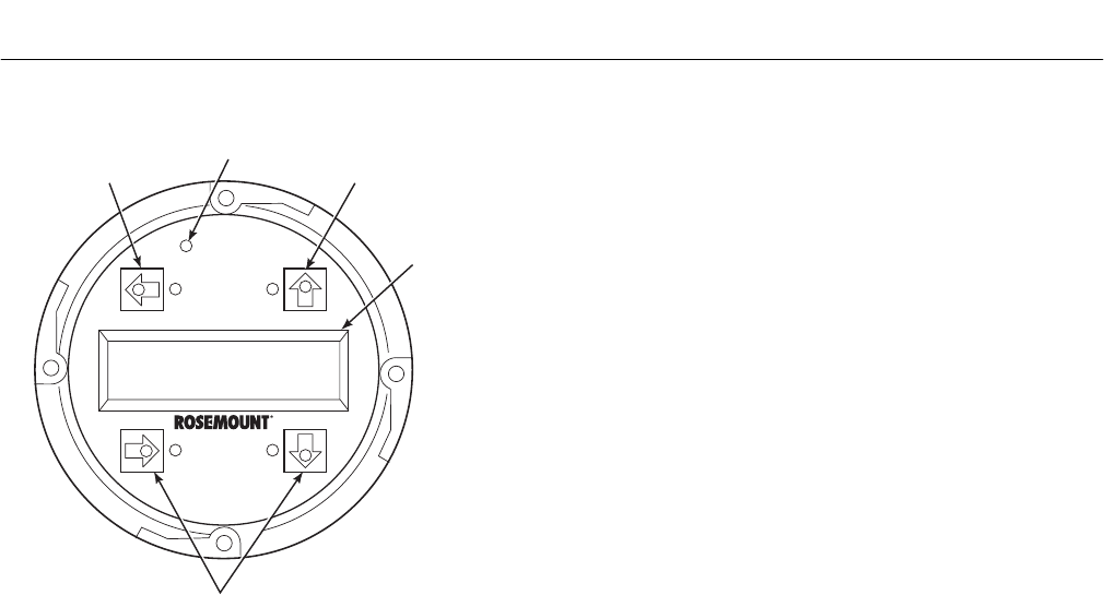
Instruction Manual
IB-106-340C Rev. 4.1
July 2004
6-2 Startup and Operation with LOI Rosemount Analytical Inc. A Division of Emerson Process Management
Hazardous Area Oxymitter 4000
LCD
DISPLAY
WINDOW
SELECTION
ARROWS
SELECTION
ARROW
37260054
SELECTION
ARROW
TOUCH
CONFIRMATION
LED
Figure 6-3. LOI Features
6-3 NAVIGATING THE LOCAL OPERATOR
INTERFACE
a. Overview
The Local Operator Interface (LOI), shown
in Figure 6-3, utilizes a bright blue gas-
florescent display. Intensity is adjustable.
There is an Infra-red LED source and a
detector for each key. The detectors can
detect a finger placed above the button
through the glass window. There is no need
to open the instrument in bad weather or in
hazardous areas in order to access the
electronics.
It should be noted that the Hazardous Area
Oxymitter 4000 also utilizes HART commu-
nications, permitting access to all instrument
functionality anywhere the 4-20 mA signal
terminates via a HART model 275/375
handheld communicator.
b. Lockout
The Local Operator Interface (LOI) has
a lockout feature that prevents nuisance
actuation by someone brushing against the
glass window, raindrops, dirt, insects, etc.
This lockout mode is automatically estab-
lished when no buttons are pushed for 30
seconds (default). This countdown to lock-
out is configurable.
In order to unlock the display, input a "Z"
pattern. First, push the top left (gray) arrow,
then the top right, followed by the bottom
left and finally the bottom right. The "LK"
notation in the upper right corner of the
display will now disappear. Push the gray
arrow at the top left hand corner once more
to enter into the menu structure. Once one
moves deeper into the menu structure,
additional time is provided to the user so
that the lockout initiation does not become
a nuisance. This additional “revert” time is
defaulted at one hour and is also user con-
figurable.
6-4 LOI KEY DESIGNATIONS
The gray key (top left) key will move one level
higher in the menu structure. When entering
numbers, this key will move the cursor to the
left. This key also doubles as an “Enter” key,
once numbers are entered, and when the cursor
is moved to it’s left-most position. The new data
entry value will appear in the top line of the LOI
display once it’s accepted.
The blue key (bottom left) acts as a selector
when choosing from among a number of menu
items. This key also will move the cursor to the
right when entering numbers.
Up/Down keys (to the left side of the keypad)
are used to increment up and down when
selecting from a series of menu picks. They are
also used for incrementing values up and down
for data input.
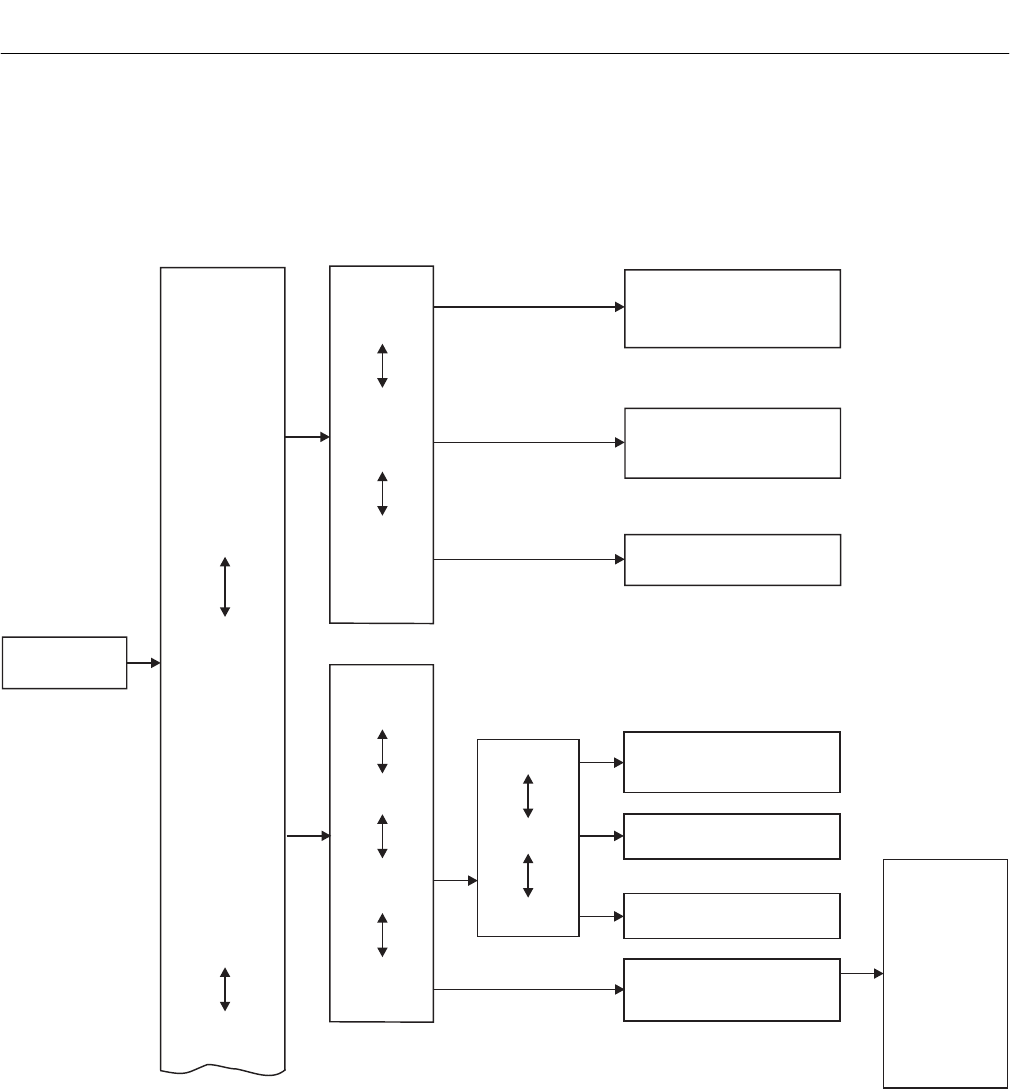
Instruction Manual
IB-106-340C Rev. 4.1
July 2004
Rosemount Analytical Inc. A Division of Emerson Process Management Startup and Operation with LOI 6-3
Hazardous Area Oxymitter 4000
6-5 LOI MENU TREE
This LOI menu for the Oxymitter 4000 is shown
in Figure 6-4. This menu tree is specific to the
Oxymitter 4000. The menu tree will assist in
navigating the LOI.
Menu items in normal text display information,
only. Menu Items in italics permit data entry.
Menu items in bold text are procedures.
Temperatures
SENSOR
DATA Voltages
O2 Analog % _____%
O2 Analog mA ____mA
Output Values
O2 2.59% LK
normal
%
37260017
(CONTINUED ON
SHEET 2)
O2 Temp _____dgC
O2 Temp-MAX _____dgC
Board Temp _____dgC
Board Temp-MAX _____dgC
O2 Sensor _____mV
O2 Sensor T/C _____mV
Board Temp IC _____mV
CALIBRATION
Start Calib
Abort Calib
Cal Constants
O2 Slope ____ mV/D
O2 Constant ____ mV
O2 Cell Imped ____ ohm
Cal Status
Current Calib
Previous
Failed Calib
Pre O2 Slope _____mV/D
Pre O2 Constant _______mV
Bad O2 Slope _____mV/D
Bad O2 Constant _______mV
Calib Step _______
___Sec.
___H
Calib Time
Next O2 Cal
NOTE
For this menu column, the
selections in are
user configurable. All other
parameters are display only.
Italics
Idle
Recommend Cal
Apply Gas 1
Flow Gas 1
Read Gas 1
Done Gas 1
Apply Gas 2
Flow Gas 2
Read Gas 2
Done Gas 2
Cal Abort
Stop Gas
Purge
NOTE
Use Z pattern
touch command
to unlock menu.
Figure 6-4. Local Operator Interface Menu Tree (Sheet 1 of 2)
6
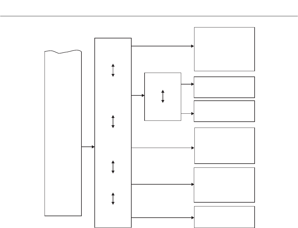
Instruction Manual
IB-106-340C Rev. 4.1
July 2004
6-4 Startup and Operation with LOI Rosemount Analytical Inc. A Division of Emerson Process Management
Hazardous Area Oxymitter 4000
SYSTEM
O2 Gas 1
O2 Gas 2
O2-Reset Vals
O2
O2 Cal Intervl
O2-
Gas Time
Purge Time
_____%
_____%
____H
___Sec.
Yes/No
Yes/No
____H
___Sec.
Yes/No
Out Tracks
Next Cal
Auto Calib?
O2 Type
O2 Range
O2 Alarm Leve
_______
______%
l _____mA
Do O2 Trim
Calib Setup
Input/Output
Parameters
Status
Software
37260018
(CONTINUED FROM
SHEET 1)
Analog
Digital
NOTE
In column four of this menu, the selections in are user configurable. text selections are
procedures; related instructions are displayed on the LOI. All other parameters are display only.
Italics Bold
Version xxx
Checksum xxx
Build Number xxx
Build Date xxxxxx
Test Code xx
SW Err File xx
SW Err Line xx
Alarms __________
PID Parameters 115/220
Yes/No
(Cal. required after reset)
Reset Device?
O2 Slope
O2 Constant
O2 T90 Time
Auto Tune?
Lockout Time
Revert Time
Luminance
____ mV/D
____ mV
0:00
Yes/No
0:00
0:00
______
Logic IO Mode
Low
See Table 4-1
O2 Alarm
Force Output
See para. 9-3b
Input State _______
_______
Figure 6-4. Local Operator Interface Menu Tree (Sheet 2 of 2)
6-6 HAZARDOUS AREA OXYMITTER 4000
SETUP AT THE LOI
In setting up the Hazardous Area Oxymitter
4000 from the LOI, it’s best to start at the
SYSTEM/Calibration Setup menu, Figure 6-4.
a. SYSTEM/Calibration Setup
1. O2 Gas #1 – Enter the high or low cal
gas value (the order is not important).
2. O2 Gas #2 – Enter the second cal gas
value.
NOTE
Refer to Section 9, MAINTENANCE AND
SERVICE, for calibration instructions.
NOTE
Rosemount Analytical recommends
0.4% O2 and 8% O2 for calibration gases.
3. O2 - Reset Values – Resets factory
default values.
4. O2 Output Tracks – 4 to 20 mA signal
can be held at the last value during
calibration, or the signal can be left to
track the cal gases.
5. O2 Cal Interval – If automatic calibra-
tion is selected, this selects the interval
between calibrations.
6. O2-Next Cal – If automatic calibration
is selected, this selects the time until
the first initial calibration takes place.

Instruction Manual
IB-106-340C Rev. 4.1
July 2004
Rosemount Analytical Inc. A Division of Emerson Process Management Startup and Operation with LOI 6-5
Hazardous Area Oxymitter 4000
7. Gas Time – How long should each cal
gas flow. Factory default is 300 sec-
onds, but the user may want to vary
this depending upon the length of cali-
bration gas tubing runs.
8. Purge Time – Used if the O2 output is
selected to hold the last value during
calibration. After the second cal gas is
removed, how long until the sensor
comes back to the normal process
reading, and the 4-20 mA signal can
be released.
9. Auto Calib? – Select “Yes” if an SPS
or IMPS autocalibration system is part
of the system.
b. SYSTEM/Input/Output
1. Analog – Pertaining to the analog
4-20 mA signal representing O2.
(a) O2 Type – 4-20 mA signal may
be configured to increase with
increasing O2 or the reverse.
(b) O2 Range – Upper O2 range is
user selectable.
(c) O2 Alarm Level – User can config-
ure the digital output to alarm at a
given O2 level.
(d) Do O2 Trim – Procedure for cali-
brating the 4-20 mA signal to a
precision mA source. Procedure
is intuitive.
2. Digital – A bi-directional logic signal
may be configured as an alarm, or as
a calibration handshake signal.
(a) Logic I/O Mode – One of 9 different
sets of conditions can be set for
the digital signal. See Table 8-2.
(b) Low O2 Alarm – If any of the con-
ditions noted above include a low
O2 process alarm, set the value
here.
(c) Input State – Notes the current
condition of the bi-directional digital
signal.
(d) Force Output – Forces the output
state of the signal to either open or
closed. This is used primarily when
diagnosing potential problems with
this signal.
c. SYSTEM/Parameters
1. O2 Slope – O2 slope is data regarding
the strength of the sensing cell output.
This information is automatically cal-
culated after a calibration, and the user
does not normally input this data.
2. O2 Constant – O2 constant is the
amount of voltage a cell generates
with ambient air as the calibration gas.
Again, this is normally calculated as a
result of calibration, and is not normally
input by the user.
3. O2 T90 Time – Some users may feel
that the O2 reading is too active for
certain processes. This feature permits
the user to dampen the O2 signal. The
default value is zero seconds damp-
ening.
4. Auto Tune – The electronics detects
the line voltage powering the instru-
ment automatically, and picks proper
algorithms for heater control. User can
force a high voltage algorithm, or a low,
but Auto Tune is the default, and is
recommended.
5. Lockout Time – Keypad lockout time
default is 30 sec., but is user configur-
able. A “Z” keypad pattern will unlock
the keypad.
6. Revert Time – Once a user goes one
level deep into the menu structure, an
additional “revert time” is provided to
prevent nuisance lockouts. One hour is
the default, and it is user configurable.
7. Luminance – Gas florescence bright-
ness is user adjustable.
6
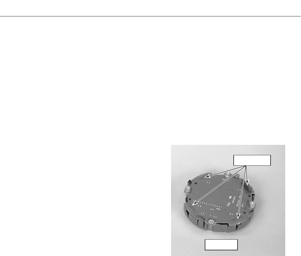
Instruction Manual
IB-106-340C Rev. 4.1
July 2004
6-6 Startup and Operation with LOI Rosemount Analytical Inc. A Division of Emerson Process Management
Hazardous Area Oxymitter 4000
d. SYSTEM/Status
1. Alarms – Diagnostic alarms. See
Section 8, TROUBLESHOOTING.
2. PID Parameter – Displays the line volt-
age, powering the Oxymitter, and infers
the temperature control algorithm being
used to control heater temperature.
3. Reset Device – Device can be reset
here as opposed to re-powering. Cali-
bration parameters will be lost.
e. SYSTEM/Software
This is data regarding the Oxymitter 4000
software version, and errors that may have
occurred.
f. SENSOR DATA
Displays information about the O2 cell and
thermocouple.
1. Temperatures
(a) O2 Temp – Indicates the thermo-
couple temperature at the sensing
cell; this should always be 736°C.
(b) O2 Temp Max. – Maximum tem-
perature the cell has seen. (Some
process temperatures can exceed
the 736°C setpoint temperature,
and this will indicate this condition.)
(c) Board Temp – The temperature
inside the Oxymitter electronics
housing (85°C is the max.).
(d) Board Temp Max. – This is the
maximum temperature that the
electronics has experienced over
time.
6-7 LOI INSTALLATION
The LOI connects to the top of the electronic
assembly in the electronics housing. There are
four matching connectors on the back of the LOI
module, Figure 6-5, that allow the LOI to be ori-
ented as desired by the user.
37260055
CONNECTOR
RECEPTACLES
LOI MODULE
REAR VIEW
Figure 6-5. LOI Module Connectors
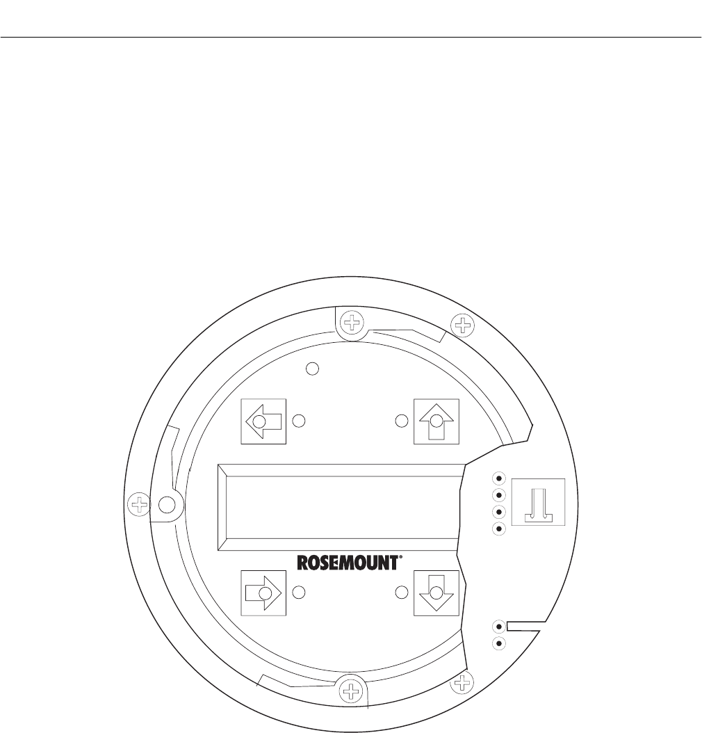
Instruction Manual
IB-106-340C Rev. 4.1
July 2004
Rosemount Analytical Inc. A Division of Emerson Process Management Startup and Operation with LOI 6-7
Hazardous Area Oxymitter 4000
6-8 OXYMITTER 4000 TEST POINTS
Refer to Figure 6-6. System test points are
located on the board below the LOI module.
Test points 1 through 6 allow you to monitor
with a multimeter: the heater thermocouple,
the O2 cell millivolt, and the process O2.
a. TP1 and TP2 monitor the oxygen cell
millivolt output which equates to the
percentage of oxygen present.
b. TP3 and TP4 monitor the heater thermo-
couple.
c. TP5 and TP6 monitor the process gas or
the calibration gas parameter.
6-9 MODEL 751 REMOTE POWERED LOOP
LCD DISPLAY (OPTIONAL)
Refer to Remote Powered Loop LCD manual
for calibration and operation.
TP1 J1
TP2
TP3
RED
YEL
GRN
ORG
TP4
TP5
TP6
37260037
Figure 6-6. Test Points
6

Instruction Manual
IB-106-340C Rev. 4.1
July 2004
6-8 Startup and Operation with LOI Rosemount Analytical Inc. A Division of Emerson Process Management
Hazardous Area Oxymitter 4000

Instruction Manual
IB-106-340C Rev. 4.1
July 2004
Rosemount Analytical Inc. A Division of Emerson Process Management HART/AMS 7-1
Hazardous Area Oxymitter 4000
SECTION 7
HART/AMS
The HART option is not protected by
energy limiting barriers. It must not be
interfaced from within the hazardous
area. The 4-20 mA cables should be
routed and the connections made out-
side the hazardous area. Note that this
is the case even when using the in-
trinsically safe version of the handheld
communicator.
7-1 OVERVIEW
The HART Communicator is a handheld com-
munications interface device. It provides a
common communications link to all microproc-
essor-based instruments that are HART com-
patible. The handheld communicator contains
an 8 x 21 character liquid crystal display (LCD)
and 25 keys. A pocket-sized manual, included
with the HART Communicator, details the spe-
cific functions of all the keys.
To interface with the Hazardous Area Oxymitter
4000, the HART Communicator requires a ter-
mination point along the 4-20 mA current loop
and a minimum load resistance of 250 ohms
between the communicator and the power
supply.
The HART Communicator accomplishes its task
using a frequency shift keying (FSK) technique.
With the use of FSK, high-frequency digital
communication signals are superimposed on
the Hazardous Area Oxymitter 4000’s 4-20 mA
current loop. The HART communicator does not
disturb the 4-20 mA signal, since no net energy
is added to the loop.
The HART Communicator may be interfaced
with a personal computer (PC), providing that
special software has been installed. To connect
the HART Communicator to a PC, an interface
adapter is required. Refer to the proper HART
Communicator documentation in regard to the
PC interface option.
7-2 HART COMMUNICATOR SIGNAL LINE
CONNECTIONS
The HART Communicator can connect to the
Hazardous Area Oxymitter 4000’s analog output
signal line at any wiring termination in the 4-20
mA current loop. There are two methods of
connecting the HART Communicator to the
signal line. For applications in which the signal
line has a load resistance of 250 ohms or more,
refer to method 1. For applications in which the
signal line load resistance is less than 250
ohms, refer to method 2.
7
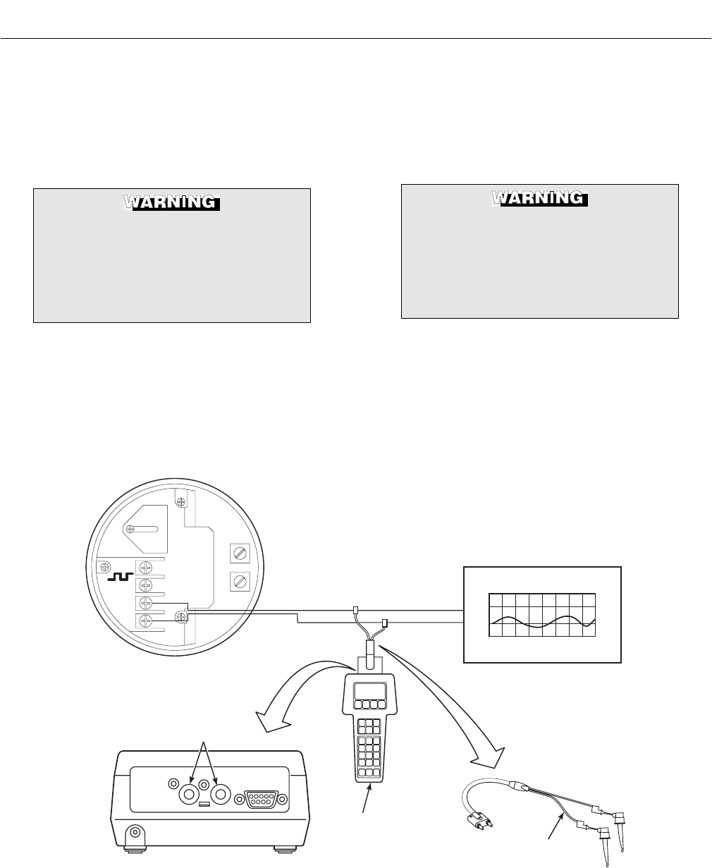
Instruction Manual
IB-106-340C Rev. 4.1
July 2004
7-2 HART/AMS Rosemount Analytical Inc. A Division of Emerson Process Management
Hazardous Area Oxymitter 4000
a. Method 1, For Load Resistance ≥ 250
Ohms
Refer to Figure 7-1 and the following steps
to connect the HART Communicator to a
signal line 250 ohms or more of load
resistance.
Explosions can result in death or seri-
ous injury. Do not make connections
to the HART Communicator's serial
port, 4-20 mV signal line, or NiCad re-
charger jack in an explosive
atmosphere.
Using the supplied lead set, connect the
HART Communicator in parallel with to the
Hazardous Area Oxymitter 4000. Use any
wiring termination points in the analog out-
put 4-20 mA signal line.
b. Method 2, For Load Resistance < 250
Ohms
Refer to Figure 7-2 and the following steps
to connect the HART Communicator to a
signal line with less than 250 ohms load
resistance.
Explosions can result in death or seri-
ous injury. Do not make connections
to the HART Communicator's serial
port, 4-20 mA signal line, or NiCad re-
charger jack in an explosive
atmosphere.
1. At a convenient point, break the analog
output 4-20 mA signal line and install
the optional 250 ohm load resistor.
2. Plug the load resistor into the loop
connectors (located on the rear panel
of the HART Communicator).
LOOP CONNECTORS USE INTERFACE
00275 0013 ONLY
SERIAL PORT & BATTERY
CHARGER MUST
NOT BE USED IN
HAZARDOUS AREAS
SERIAL PORT
AC L1
AC N
+
+
-
-
4-20
TERMINAL BLOCK
LOOP CONNECTORS
4-20 mA SIGNAL LINE
HART
COMMUNICATOR
RL 250≥Ω
ANALOG OUTPUT DEVICE
LEAD SET
HART COMMUNICATOR
REAR PANEL
23230001
Figure 7-1. Signal Line Connections, ≥ 250 Ohms Load Resistance
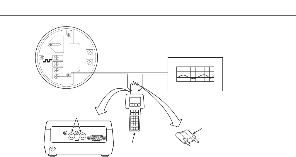
Instruction Manual
IB-106-340C Rev. 4.1
July 2004
Rosemount Analytical Inc. A Division of Emerson Process Management HART/AMS 7-3
Hazardous Area Oxymitter 4000
LOOP CONNECTORS USE INTERFACE
00275 0013 ONLY
SERIAL PORT & BATTERY
CHARGER MUST
NOT BE USED IN
HAZARDOUS AREAS
SERIAL PORT
AC L1
AC N
+
+
-
-
4-20
TERMINAL BLOCK
LOOP CONNECTORS
4-20 mA SIGNAL LINE
HART
COMMUNICATOR
RL < 250Ω
ANALOG OUTPUT DEVICE
250 OHM
LOAD
RESISTOR
(NOTE)
HART COMMUNICATOR
REAR PANEL
NOTE: THE SIGNAL LOOP MUST BE BROKEN
TO INSERT THE OPTIONAL 250 OHM
LOAD RESISTOR. 23230002
Figure 7-2. Signal Line Connections, < 250 Ohms Load Resistance
7-3 HART COMMUNICATOR PC
CONNECTIONS
There is an option to interface the HART Com-
municator with a personal computer. Load the
designated AMS software into the PC. Then link
the HART Communicator to the PC using the
interface PC adapter that connects to the serial
port (on the communicator rear panel).
Refer to the proper HART Communicator docu-
mentation in regard to the PC interface option.
7-4 OFF-LINE AND ON-LINE OPERATIONS
The HART Communicator can be operated both
off-line and on-line.
a. Off-line operations are those in which the
communicator is not connected to the Haz-
ardous Area Oxymitter 4000. Off-line op-
erations can include interfacing the HART
Communicator with a PC (refer to applica-
ble HART documentation regarding
HART/PC applications.
b. In the on-line mode, the communicator is
connected to the 4-20 mA analog output
signal line. The communicator is connected
in parallel to the Hazardous Area Oxymitter
4000 or in parallel to the 250 ohm load
resistor.
NOTE
If the HART Communicator is turned
on while connected to the 4-20 mA
analog output signal line, an undefined
status indication appears while the
communicator warms up. Wait until
the warmup period ends to continue.
c. The opening menu displayed on the LCD is
different for on-line and off-line operations.
When powering up a disconnected (off-line)
communicator, the LCD will display the
Main Menu. When powering up a connected
(on-line) communicator, the LCD will display
the On-line Menu. Refer to the HART
Communicator manual for detailed menu
information.
7

Instruction Manual
IB-106-340C Rev. 4.1
July 2004
7-4 HART/AMS Rosemount Analytical Inc. A Division of Emerson Process Management
Hazardous Area Oxymitter 4000
7-5 LOGIC I/O CONFIGURATIONS
The Hazardous Area Oxymitter 4000 logic I/O
output can be configured for ten different modes
through HART/AMS. The factory default condi-
tion is Mode 5. A list of possible configurations
appear in Table 7-1.
The Unit Alarm configuration available for
Modes 1, 3, 5, and 7 refers to the diagnostic
alarm faults in Table 8-1.
7-6 HART/AMS MENU TREE FOR HAZARDOUS
AREA OXYMITTER 4000 APPLICATIONS
This section consists of a menu tree for the
HART Communicator. This menu is specific to
Hazardous Area Oxymitter 4000 applications.
Table 7-1. Logic I/O Configuration (as set at HART/AMS or LOI)
Mode Configuration
0 The unit is not configured for any alarm condition.
1 The unit is configured for a Unit Alarm.
2 The unit is configured for Low O2.
3 The unit is configured for both a Unit Alarm and Low O2.
4 The unit is configured for a High AC Impedance/CALIBRATION
RECOMMENDED.
5* The unit is configured for both a Unit Alarm and a High AC Imped-
ance/CALIBRATION RECOMMENDED.
6 The unit is configured for both a Low O2 and High AC Impedance/CALIBRATION
RECOMMENDED.
7 The unit is configured for a Unit Alarm, a Low O2, and a High AC
Impedance/CALIBRATION RECOMMENDED.
8** The unit is configured for a calibration handshake with an IMPS 4000 or SPS
4000. CALIBRATION RECOMMENDED will initiate the calibration cycle.
9 The unit is configured for a calibration handshake. CALIBRATION RECOM-
MENDED will not initiate the calibration cycle with an IMPS 4000 or SPS 4000.
*The default condition for a Hazardous Area Oxymitter 4000 without an IMPS 4000 or SPS 4000.
**The default condition for a Hazardous Area Oxymitter 4000 with an IMPS 4000 or SPS 4000.
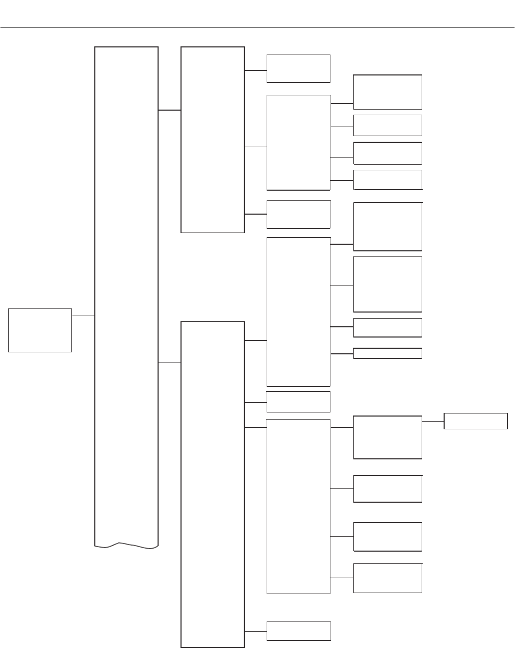
Instruction Manual
IB-106-340C Rev. 4.1
July 2004
Rosemount Analytical Inc. A Division of Emerson Process Management HART/AMS 7-5
Hazardous Area Oxymitter 4000
O2 value
O2 cell temp
CJ temp
VIEW FLD
DEV VARS
PV is
PV O2 value
PV % rnge
PV AO
SV is Cold Junct
SV __ mV
PROCESS
VARIABLES
DIAG/SERVICE
VIEW SV
VIEW TV
VIEW PV-Aout
VIEW OUTPUT
VARS
VIEW 4V
TV is Cell
TV __ mV
4V is Cell TC
4V __ mV
Open T/C
Shorted T/C
Reversed T/C
Heater Open
Cell Temp Very HI
High Case Temp
Cell Temp Low
Cell Temp High
Cell Open
High Cell Imp.
CK.ER - EEPROM
Cal.Error Slope
Cal. Recommended
AO1 Out Rnge lim
Cal. Error Const.
Last Cal. Failed
Cell mV
CellTCmV
CJ mV
VIEW FLD
DEV mV
STATUS
AO Fixed
Max Case Temp
AO Saturated
Operate Model
Status Group 3
Status Group 2
Status Group 1
LOOP TEST Loop test
method...
O2 Cal
Optrak TG?
CalState
PERFORM O2
CAL
O2 CALIBRATE
CalState
TimeRemain
Present O2
O2 CAL
STATUS
Cal slope
Cal const
Cell Imp
LAST
CALCONSTANTS
Reset
CalConstants
method...
RESET
CALCONSTANTS
D/A trim method
D/A TRIM
O2 Cal method...
Refer to para. 7-7
for the complete O2
calibration method
using the HART
Communicator.
DEVICE SETUP
PV
PV AO
PV LRV
PV URV
(CONTINUED ON
SHEET 2)
37270003
Figure 7-3. HART/AMS Menu Tree (Sheet 1 of 3)
7
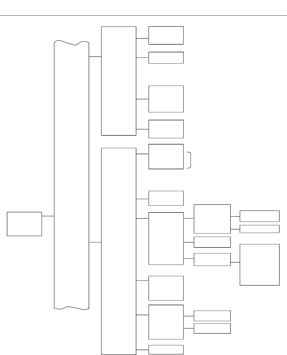
Instruction Manual
IB-106-340C Rev. 4.1
July 2004
7-6 HART/AMS Rosemount Analytical Inc. A Division of Emerson Process Management
Hazardous Area Oxymitter 4000
DEVICE SETUP
PV
PV AO
PV LRV
PV URV
(CONTINUED ON
SHEET 3)
Tag
ASSIGN
PV&SV
SELECT O2
RANGE
DEVICE
INFORMATION
S/W VERSION
INFO
Dev id
Descriptor
Message
Date
Final asmbly num
Snsr s/n
Ver
Chk sum
Bld num
Bld date
O2
O2 CELLTEMP
COLDJUNCTEMP
O2 CELL MV
O2 CELLTCMV
COLD JUNC MV
PV URV
PV LRV
PV % rnge
ANALOG
OUTPUT
HART OUTPUT
ALARM
OUTPUT
SLOPE
CONSTANT
OP locks
OP tracks
Manual
Auto
HighTG
LowTG
OPtrak TG?
TGtime
PurgeTime
Cal Mode
Cal Intrvl h
Next CalTime h
LoAlarmSP
SENSORS
LIMITS DISPLAYED
SIGNAL
CONDITION
OUTPUT
CONDITION
O2
O2
CALIBRATION
O2 ALARMS
(CONTINUED FROM
SHEET 1)
BASIC SETUP
DETAILED
SETUP
PV AO ____ mA
PV AO Alrm typ
LOOP TEST
D/A TRIM
Poll addr
Num req preams
Logic I/O Pin State
Logic I/O Pin Mode
Loop test
method...
D/A trim method...
No Alarm
Unit Alarm
Low O2 Alarm
Low O2/Unit Alarm
Cal Rec
Cal Rec/Unit Alarm
Low O2/Cal Rec
Low O2/Unit/Cal Rec
Cal Rec/Handshake
Handshake
PV is Oxygen
SV is Cold Junct
TV is Cell
4V is Cell TC
URV ____%
LRV ____%
35910004
Figure 7-3. HART/AMS Menu Tree (Sheet 2 of 3)
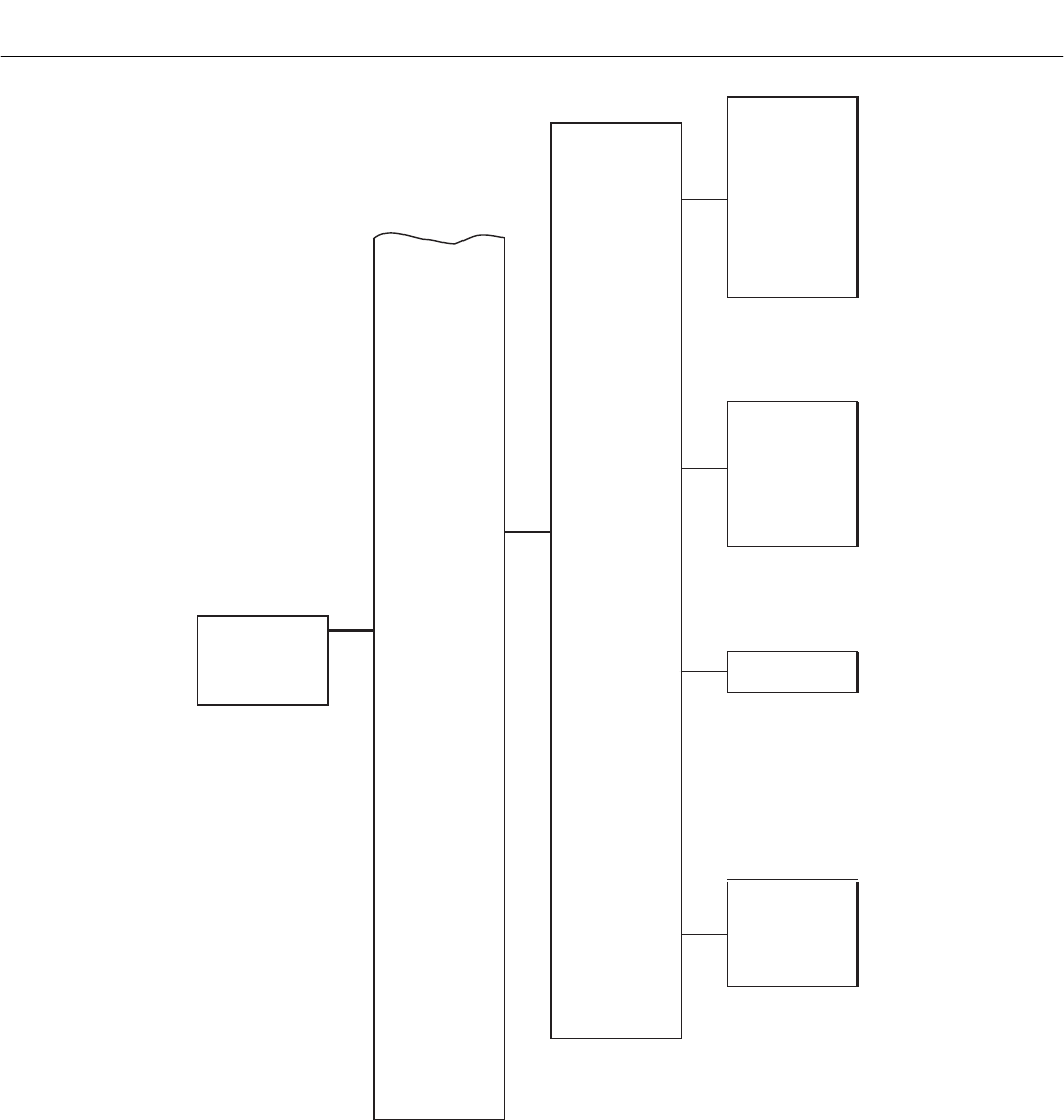
Instruction Manual
IB-106-340C Rev. 4.1
July 2004
Rosemount Analytical Inc. A Division of Emerson Process Management HART/AMS 7-7
Hazardous Area Oxymitter 4000
DEVICE SETUP
PV
PV AO
PV LRV
PV URV
(CONTINUED FROM
SHEET 2)
Manufacturer
Model
Dev id
Tag
Descriptor
Message
Date
Final asmbly num
Snsr s/n
Fld dev rev
Hardware rev
Software rev
Universal rev
Optrak TG?
Tgtime
PurgeTime
LowTG
HighTG
Cal slope
Cal const
CellImp
Imp Delta
Slope
Constant
URV
LRV
LoAlarmSP
I/O Pin Mode
Poll addr
Num req preams
DEVICE
INFORMATION
CAL INFO
DEVICE CONFIG
OUTPUTS
CONFIG
REVIEW
26170030
Figure 7-3. HART/AMS Menu Tree (Sheet 3 of 3)
7
Instruction Manual
IB-106-340C Rev. 4.1
July 2004
7-8 HART/AMS Rosemount Analytical Inc. A Division of Emerson Process Management
Hazardous Area Oxymitter 4000
7-7 HART COMMUNICATOR O2 CAL METHOD
Use the following procedure to perform a
calibration using the HART Communicator. If
necessary, use the menu tree in Figure 7-3
(sheet 1 of 3) for reference.
NOTE
To select a menu item, either use the
up and down arrow keys to scroll to
the menu item and press the right
arrow key or use the number keypad
to select the menu item number. To
return to a preceding menu, press the
left arrow key.
a. From the PERFORM O2 CAL screen,
select menu item 1, O2 CAL, to access
the O2 calibration procedure.
Failure to remove the Hazardous Area
Oxymitter 4000 from automatic control
loops prior to performing this proce-
dure may result in a dangerous oper-
ating condition.
b. In the first O2 CAL screen, a “Loop should
be removed from automatic control” warning
appears. Remove the Hazardous Area
Oxymitter 4000 from any automatic control
loops to avoid a potentially dangerous op-
erating condition and press OK.
c. The next several screens indicate the cali-
bration status. At each of the following
status prompts, select menu item 2, NEXT
CAL STEP:
COMPLETE
CAL RECOMMENDED
APPLY GAS 1
GAS 1 FLOW
d. At this point, select menu item 4, EXIT, to
leave the O2 CAL procedure.
e. From the PERFORM O2 CAL screen, view
menu item 3, CALSTATE, to monitor the
calibration status as it updates. Or, access
the O2 CALIBRATE screen and select menu
item 2, O2 CAL STATUS, to view menu item
1, CAL-STATE; menu item 2, TIMERE-
MAIN; and menu item 3, PRESENT O2, as
the calibration status updates.
f. When CALSTATE displays APPLY GAS 2,
return to the O2 CAL procedure.
g. When the “Loop should be removed from
automatic control” warning appears, press
OK.
h. At the APPLY GAS 2 status prompt, select
menu item 2, NEXT CAL STEP. When the
status displays GAS 2 FLOW, select menu
item 4, EXIT, to leave the O2 CAL
procedure.
i. From the PERFORM O2 CAL screen, view
menu item 3, CALSTATE, to monitor the
calibration status as it updates. Or, access
the O2 CALIBRATE screen and select menu
item 2, O2 CAL STATUS, to view menu item
1, CAL-STATE; menu item 2, TIMERE-
MAIN; and menu item 3, PRESENT O2, as
the calibration status updates.
j. When CALSTATE displays STOP GAS,
return to the O2 CAL procedure.
k. When the “Loop should be returned to
automatic control” message appears, return
the Hazardous Area Oxymitter 4000 to the
automatic control loops previously removed
and press OK.
l. At the STOP GAS status prompt, select
menu item 2, NEXT CAL STEP. When the
status displays PURGING, select menu
item 4, EXIT, to leave the O2 CAL proce-
dure.
m. From the PERFORM O2 CAL screen, view
menu item 3, CALSTATE, to monitor the
calibration status as it updates. Or, access
the O2 CALIBRATE screen and select menu
item 2, O2 CAL STATUS, to view menu item
1, CAL-STATE; menu item 2, TIMERE-
MAIN; and menu item 3, PRESENT O2, as
the calibration status updates.
n. When CALSTATE displays COMPLETE,
the calibration is finished.

Instruction Manual
IB-106-340C Rev. 4.1
July 2004
Rosemount Analytical Inc. A Division of Emerson Process Management HART/AMS 7-9
Hazardous Area Oxymitter 4000
7-8 DEFINING A TIMED CALIBRATION VIA
HART
Use the following procedure to specify a time
interval (in hours) at which the Hazardous Area
Oxymitter 4000 will be automatically calibrated.
If necessary, use the menu tree in Figure 7-3
(sheet 2 of 3) for reference.
NOTE
To select a menu item, either use the
up and down arrow keys to scroll to
the menu item and press the right
arrow key or use the number keypad
to select the menu item number. To
return to a preceding menu, press the
left arrow key.
a. From the DEVICE SETUP screen, select
DETAILED SETUP.
b. From the DETAILED SETUP screen, select
O2 CALIBRATION.
c. From the O2 CALIBRATION screen, select
menu item 6, CAL MODE. Set the CAL
MODE to AUTO.
d. Return to the O2 CALIBRATION screen and
select menu item 7, CAL INTRVL.
e. At the prompt, input a time interval
(in hours) at which an automatic calibration
will occur; then press ENTER.
7

Instruction Manual
IB-106-340C Rev. 4.1
July 2004
7-10 HART/AMS Rosemount Analytical Inc. A Division of Emerson Process Management
Hazardous Area Oxymitter 4000
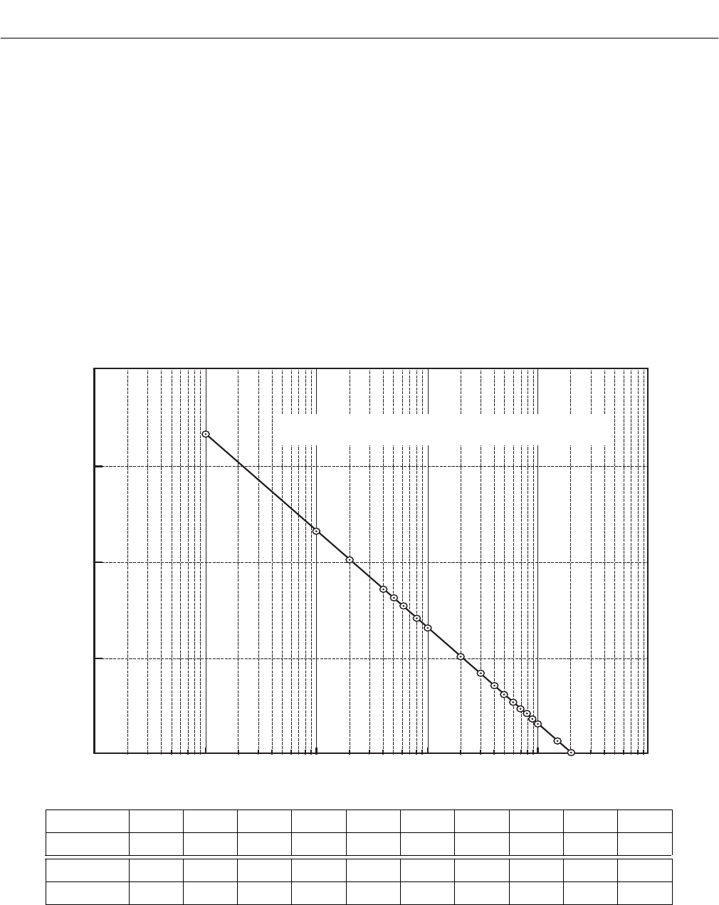
Instruction Manual
IB-106-340C Rev. 4.1
July 2004
Rosemount Analytical Inc. A Division of Emerson Process Management Troubleshooting 8-1
Hazardous Area Oxymitter 4000
SECTION 8
TROUBLESHOOTING
8-1 OVERVIEW
While the Hazardous Area Oxymitter 4000
electronics provides a significant number of
diagnostic alarms to assist in troubleshooting
potential problems, it’s good to place these
alarms in perspective with respect to the
instrument’s operating principles:
a. When the Zirconium Oxide sensing cell is
heated to its setpoint [736°C (1357°F)], the
cell will generate a voltage that represents
the difference between the process O2%
and the reference O2% inside the probe
(20.95% O2 ambient air).
b. Test points, Figure 8-1, are provided to read
the raw millivolt value generated by the
ther-mocouple that controls both the cell
temperature and the raw cell signal.
c. The cell temperature at test points 3 and 4
should always be stable at approximately
29 to 30 millivolts, which represents the
736°C setpoint temperature.
37260043
1001010.01 0.10
0
50
100
150
200
Concentration O (%)
2
EMF (mV)
O Sensor Performance at 736 C
2
O
O2 % 100201510987654
EMF(mV) -34 1.0 7.25 16.1 18.4 21.1 23.8 27.2 31.2 36.0
O2 % 3 2 1 0.8 0.6 0.5 0.4 0.2 0.1 0.01
EMF(mV) 42.3 51.1 66.1 71.0 77.5 81.5 86.3 101.4 116.6 166.8
Figure 8-1. O2 Sensor mV Reading vs. % O2 at 736°C (Reference Air, 20.9% O2)
8
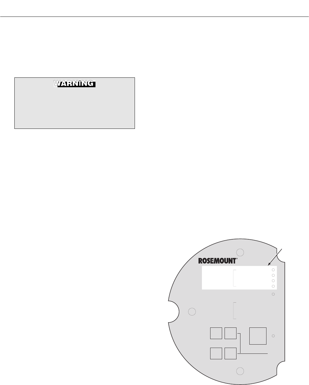
Instruction Manual
IB-106-340C Rev. 4.1
July 2004
8-2 Troubleshooting Rosemount Analytical Inc. A Division of Emerson Process Management
Hazardous Area Oxymitter 4000
d. When flowing calibration gasses, the raw
cell millivolt value at test points 1 and 2
should represent the levels on the chart in
Figure 8-1. Note that the raw cell millivolt
value increases logarithmically as the O2
concentration decreases.
Install all protective equipment covers
and safety ground leads after trouble-
shooting. Failure to install covers and
ground leads could result in serious
injury or death.
8-2 GENERAL
The troubleshooting section describes how to
identify and isolate faults that may develop in
the Hazardous Area Oxymitter 4000. When
troubleshooting, reference the following.
a. Grounding
It is essential that adequate grounding pre-
cautions are taken when installing the sys-
tem. Thoroughly check both the probe and
electronics to ensure the grounding quality
has not degraded during fault finding. The
system provides facilities for 100% effective
grounding and the total elimination of
ground loops.
b. Electrical Noise
The Hazardous Area Oxymitter 4000 has
been designed to operate in the type of
environment normally found in a boiler room
or control room. Noise suppression circuits
are employed on all field terminations and
main inputs. When fault finding, evaluate
the electrical noise being generated in the
immediate circuitry of a faulty system.
Ensure all cable shields are connected to
earth.
c. Loose Integrated Circuits
The Hazardous Area Oxymitter 4000 uses a
microprocessor and supporting integrated
circuits (IC). If the electronics are handled
roughly during installation or located where
subjected to severe vibration, the ICs could
work loose. Before troubleshooting the
system, ensure all ICs are fully seated.
d. Electrostatic Discharge
Electrostatic discharge can damage the ICs
used in the electronics. Before removing or
handling the processor board or the ICs,
ensure you are at ground potential.
8-3 ALARM INDICATIONS
The majority of the fault conditions for the
Hazardous Area Oxymitter 4000 will be indi-
cated by one of the four LEDs referred to as
diagnostic, or unit alarms on the operator’s key-
pad (Figure 8-2). An LED will flash a code that
will correspond to an error message. Only one
LED will blink at a time. An alarm code guide
is provided inside the screw-on cover for the
electronics.
Alarm indications will be also available via the
optional LOI or the HART Model 275/375 hand-
held communicator and Rosemount’s Asset
Management software. When the error is cor-
rected and/or power is cycled, the diagnostic
alarms will clear or the next error on the priority
list will appear.
DIAGNOSTIC
ALARMS
TEST
POINTS
HEATER T/C
HEATER
02 CELL
CALIBRATION
CALIBRATION RECOMMENDED
02 CELL mV +
02 CELL mv -
HEATER T/C +
HEATER T/C -
INC INC
DEC DEC
HIGH
GAS
LOW
GAS
CAL
TEST GAS +
PROCESS -
% 02
DIAGNOSTIC
LEDS
37260044
Figure 8-2. Diagnostic LEDs

Instruction Manual
IB-106-340C Rev. 4.1
July 2004
Rosemount Analytical Inc. A Division of Emerson Process Management Troubleshooting 8-3
Hazardous Area Oxymitter 4000
8-4 ALARM CONTACTS
a. If autocalibration is not utilized, a common
bi-directional logic contact is provided for
any of the diagnostic alarms listed in Table
8-1. The assignment of alarms which can
actuate this contact can be modified to one
of seven additional groupings (mode 0
through mode 7) listed in Table 7-1.
The logic contact is self-powered, +5 VDC,
with a 340 ohm series resistance. An inter-
posing relay will be required if this contact is
to be utilized to annunciate a higher voltage
device, such as a light or horn. An inter-
posing relay may also be required for cer-
tain DCS input cards.
A Potter & Brumfield R10S-E1Y1-J1.0K 3.2
mA DC or an equal interposing relay will be
mounted where the contact wires terminate
in the control/relay room.
b. If autocalibration systems are utilized, the
bi-directional logic contact is utilized as a
“hand-shake” signal between the autocali-
bration system (SPS 4000 or IMPS 4000)
and is unavailable for alarming purposes.
The following additional contacts are pro-
vided through the autocalibration systems:
1. SPS 4000 and IMPS 4000, 1-4 probes.
(a) One contact closure per probe
from the control room to the SPS
4000 or IMPS 4000 for “calibration
initiate”.
(b) One contact output per probe from
the SPS 4000 or IMPS 4000 to the
control room for “in calibration”
notification.
(c) One contact output per probe from
the SPS 4000 or IMPS 4000 to the
control room for “calibration failed”
notification. (Includes output from
pressure switch indicating “cal gas
bottles empty”).
2. Additional IMPS 4000 Alarm Contacts.
(a) One contact per IMPS 4000 for
“low calibration gas flowing”.
(b) One contact per IMPS 4000 for
“high calibration gas flowing”.
NOTE
The 4-20 mA signal can be configured
to respond normally during any cali-
bration, or can be configured to hold
the last O2 value upon the initiation of
calibration. Factory default is for the
4-20 mA signal to operate normally
throughout calibration.
NOTE
Holding the last O2 value may be useful
if several probes are being averaged
for the purpose of automatic control.
Unless several probes are being aver-
aged, always place any control loops
using the O2 signal into manual prior to
calibrating.
8-5 IDENTIFYING AND CORRECTING ALARM
INDICATIONS
For a Hazardous Area Oxymitter 4000 with a
membrane keypad, faults are indicated by four
diagnostic, or unit, alarm LEDs. A pattern of
repeating blinks define the problem. A con-
densed table of the errors and the correspond-
ing blink codes can be found on the inside right
cover of the electronics housing. Table 8-1 also
identifies the blink code and fault status of each
LED as well as the output of the 4-20 mA signal
line and a fault number that corresponds to the
troubleshooting instructions provided in this
section.
For a Hazardous Area Oxymitter 4000 with the
optional LOI, alarm messages are displayed on
the LOI display window when the alarm status
display is accessed via the LOI menu. A listing
of the alarm/fault messages and the related fault
status descriptions and fault numbers are
shown in Table 8-2.
8
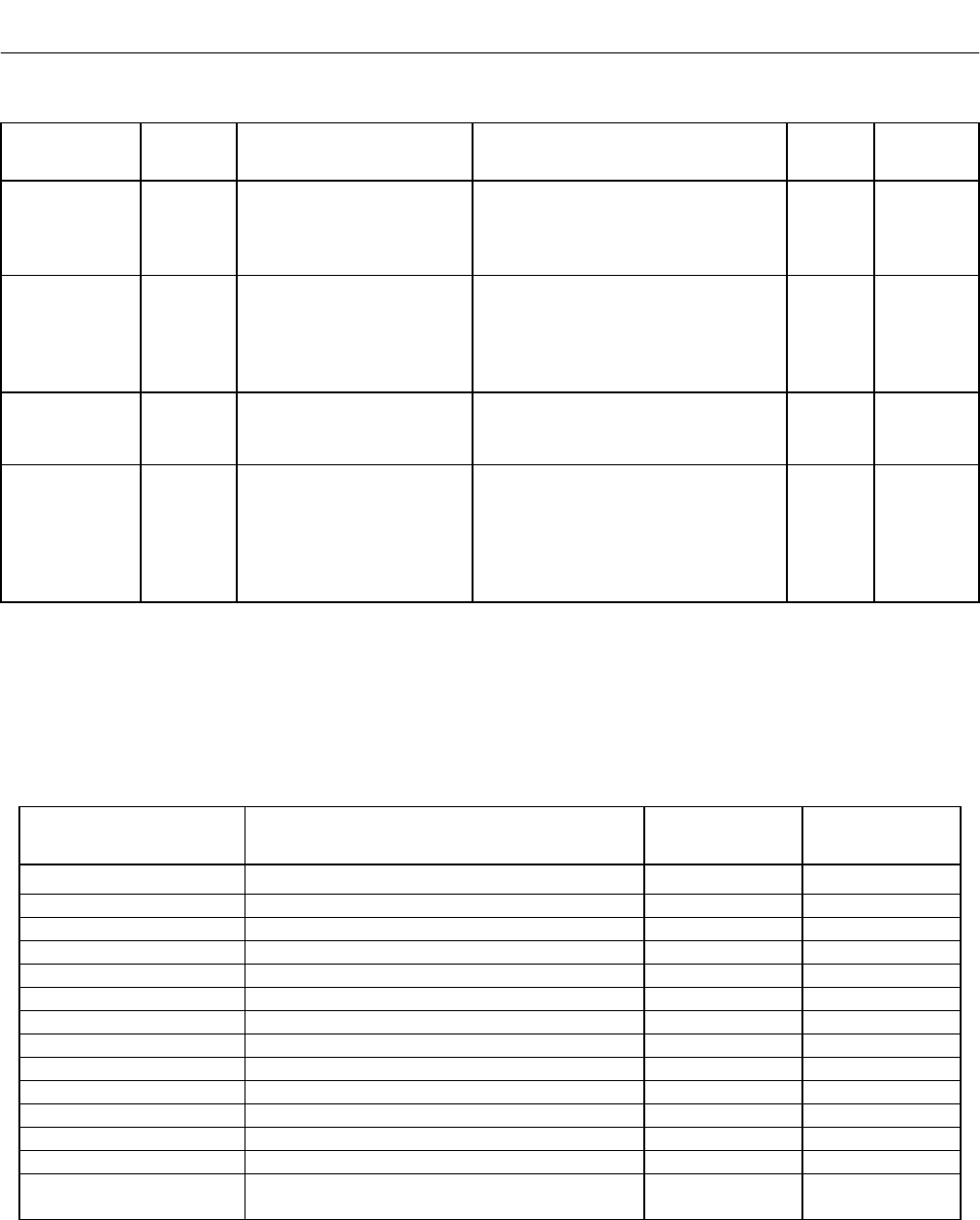
Instruction Manual
IB-106-340C Rev. 4.1
July 2004
8-4 Troubleshooting Rosemount Analytical Inc. A Division of Emerson Process Management
Hazardous Area Oxymitter 4000
Table 8-1. Diagnostic/Unit Alarm Fault Definitions – Membrane Keypad Only
LED Flashes Status 4-20 mA Line Fault
Self-
Clearing
HEATER T/C 1 OPEN Dependent on position 3 of SW2* 1 NO
2 SHORTED Dependent on position 3 of SW2* 2 NO
3 REVERSED Dependent on position 3 of SW2* 3 NO
4 A/D COMM ERROR Dependent on position 3 of SW2* 4 NO
HEATER 1 OPEN Dependent on position 3 of SW2* 5 NO
2 HIGH HIGH TEMP Dependent on position 3 of SW2* 6 NO
3 HIGH CASE TEMP Dependent on position 3 of SW2* 7 YES
4 LOW TEMP Dependent on position 3 of SW2* 8 YES
5 HIGH TEMP Dependent on position 3 of SW2* 9 YES
O2 CELL 1 HIGH mV Dependent on position 3 of SW2* 10 YES
3 BAD Track O211 YES
4 EEPROM CORRUPT Dependent on position 3 of SW2* 12 NO
CALIBRATION 1 INVALID SLOPE Track O213 YES
2 INVALID CONSTANT Track O214 YES
3 LAST CALIBRATION
FAILED
Track O215 YES
** CALIBRATION
RECOMMENDED
Track O2YES
* Critical alarm conditions will render the O2 measurement as unusable, and any of these events will cause the
4-20 mA signal to go to a user-selectable limit of 3.5 mA or 21.6 mA (position 3 of SW2). Factory default value
is 3.5 mA. Alarms which are not “self-clearing” will require recycling of power to the electronics.
** The CALIBRATION RECOMMENDED alarm flashes the Calibration Recommended alarm LED on the opera-
tor’s keypad.
Table 8-2. Diagnostic/Unit Alarm Fault Definitions – LOI
Message Status
Fault
Number
Self-
Clearing
O2 T/C OPEN HEATER T/C OPEN 1 NO
O2 T/C SHORTED HEATER T/C SHORTED 2 NO
O2 T/C REVERSED HEATER T/C POLARITY REVERSED 3 NO
ADC ERROR A/D COMM ERROR 4 NO
O2 HEATER OPEN O2 HEATER OPEN 5 NO
VERY HI O2 TEMP VERY HIGH PROCESS TEMPERATURE 6 NO
BOARD TEMP HI ELECTRONICS OVERHEATED 7 YES
O2 TEMP LOW LOW PROCESS TEMPERATURE 8 YES
O2 TEMP HI HIGH PROCESS TEMPERATURE 9 YES
O2 CELL OPEN O2 CELL OPEN 10 YES
O2 CELL BAD O2 CELL FAILED 11, 13, 14 YES
EEPROM CORRUPT EEPROM FAILED 12 NO
CALIB FAILED LAST CALIBRATION FAILED 15 YES
LINE FREQ ERROR INCORRECT INPUT LINE FREQUENCY
DETECTED ON POWER UP
NO

Instruction Manual
IB-106-340C Rev. 4.1
July 2004
Rosemount Analytical Inc. A Division of Emerson Process Management Troubleshooting 8-5
Hazardous Area Oxymitter 4000
Alarms
O2 T/C Open
LOI
KEYPAD
DIAGNOSTIC
ALARMS
TEST
POINTS
HEATER T/C
HEATER
O2 CELL
CALIBRATION
CALIBRATION RECOMMENDED
O2 CELL mV +
O2 CELL mv -
HEATER T/C +
HEATER T/C -
INC INC
DEC DEC
HIGH
GAS
LOW
GAS
CAL
TEST GAS +
PROCESS -
% O2
SW2
TP1 J1
TP2
TP3
RED
YEL
GRN
ORG
TP4
TP5
TP6
ON
37260019
Figure 8-3. Fault 1, Open Thermocouple
a. Fault 1, Open Thermocouple
Figure 8-3 shows the electronic assembly
for a Hazardous Area Oxymitter 4000 with
a membrane keypad (upper view) and a
Hazardous Area Oxymitter 4000 with an
LOI (lower view). The upper view also
shows J1 and test points TP1 through TP6,
located on the microprocessor board, below
the membrane keypad or the LOI module.
Membrane Keypad. When Fault 1 is
detected, the HEATER T/C LED flashes
once, pauses for three seconds, and
repeats.
1. Check connector J1. Ensure the con-
nector is properly seated.
2. Using a multimeter, measure the volt-
age from TP3+ to TP4-. If the reading
is 1.2 VDC ±0.1 VDC, the thermocou-
ple is open.
3. Remove power. Disconnect J1. Meas-
ure the resistance across the red and
yellow thermocouple leads. The resis-
tance should be approximately 1 ohm.
4. If the thermocouple is open, see para-
graph 9-4g, Heater Strut Replacement.
LOI. When Fault 1 is detected, the LOI
displays the “O2 T/C Open” message.
1. Remove power. Unscrew and remove
the LOI module from the electronic
assembly.
2. Reconnect power to the Oxymitter
4000.
3. Perform the diagnostic steps 1 through
4 shown for the membrane keypad.
8
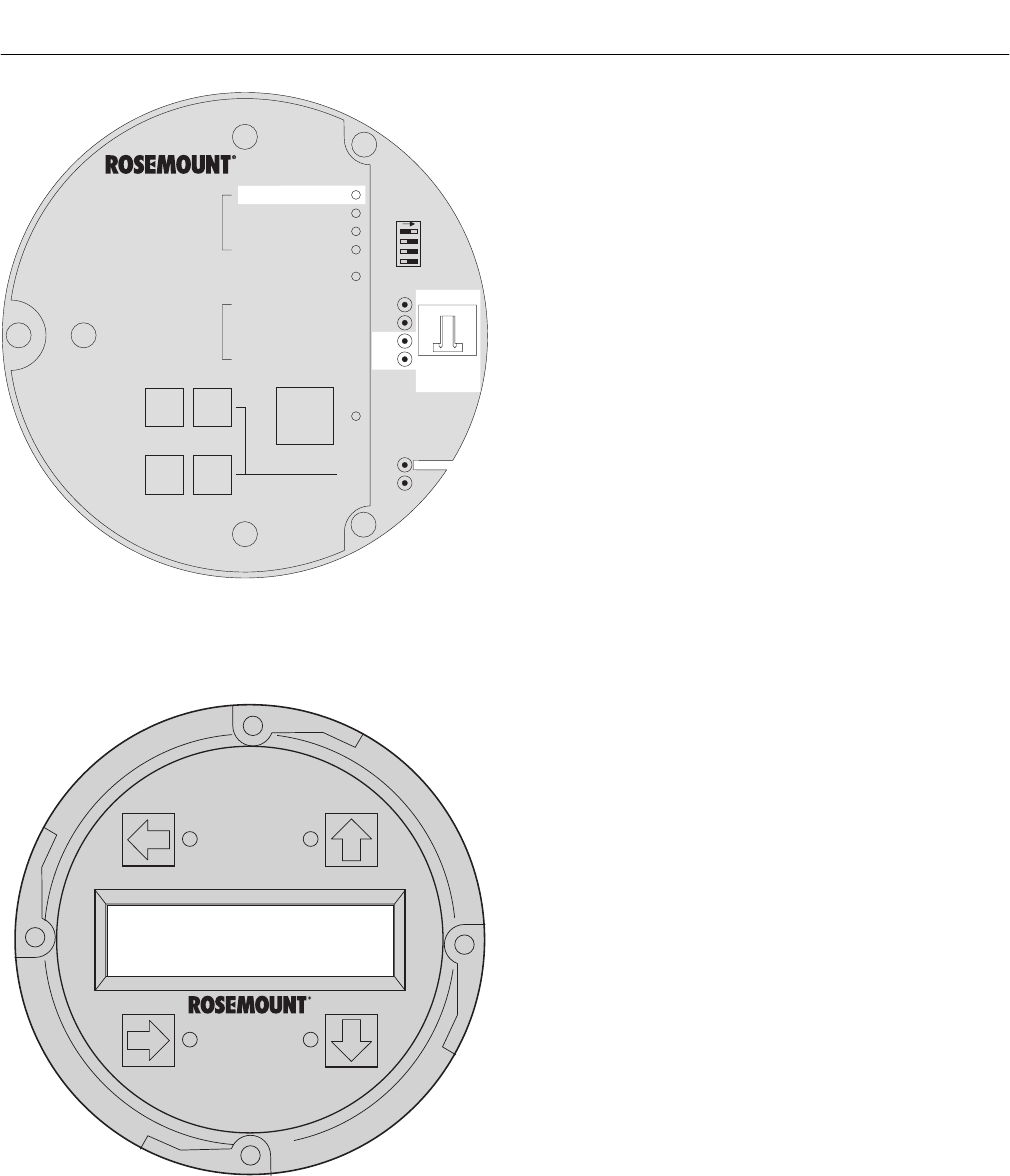
Instruction Manual
IB-106-340C Rev. 4.1
July 2004
8-6 Troubleshooting Rosemount Analytical Inc. A Division of Emerson Process Management
Hazardous Area Oxymitter 4000
Alarms
O2 T/C Shorted
LOI
KEYPAD
DIAGNOSTIC
ALARMS
TEST
POINTS
HEATER T/C
HEATER
O2 CELL
CALIBRATION
CALIBRATION RECOMMENDED
O2 CELL mV +
O2 CELL mv -
HEATER T/C +
HEATER T/C -
INC INC
DEC DEC
HIGH
GAS
LOW
GAS
CAL
TEST GAS +
PROCESS -
% O2
SW2
TP1 J1
TP2
TP3
RED
YEL
GRN
ORG
TP4
TP5
TP6
ON
37260020
Figure 8-4. Fault 2, Shorted Thermocouple
b. Fault 2, Shorted Thermocouple
Figure 8-4 shows the electronic assembly
for a Hazardous Area Oxymitter 4000 with
a membrane keypad (upper view) and a
Hazardous Area Oxymitter 4000 with an
LOI (lower view). The upper view also
shows J1 and test points TP1 through TP6,
located on the microprocessor board, below
the membrane keypad or the LOI module.
Membrane Keypad. When Fault 2 is
detected, the HEATER T/C LED flashes
twice, pauses for three seconds, and
repeats.
1. Using a multimeter, measure the volt-
age from TP3+ to TP4-. If the reading
is 0 ±0.5 mV, then a shorted thermo-
couple is likely.
2. Remove power and disconnect J1.
3. Measure the resistance from TP3+
to TP4-. The reading should be ap-
proximately 20K ohms.
4. If so, the short is not on the PC board.
The thermocouple wiring or the ther-
mocouple is shorted. See paragraph
9-4g, Heater Strut Replacement.
LOI. When Fault 2 is detected, the LOI
displays the “O2 T/C Shorted” message.
1. Remove power. Unscrew and remove
the LOI module from the electronic
assembly.
2. Reconnect power to the Oxymitter
4000.
3. Perform the diagnostic steps 1 through
4 shown for the membrane keypad.
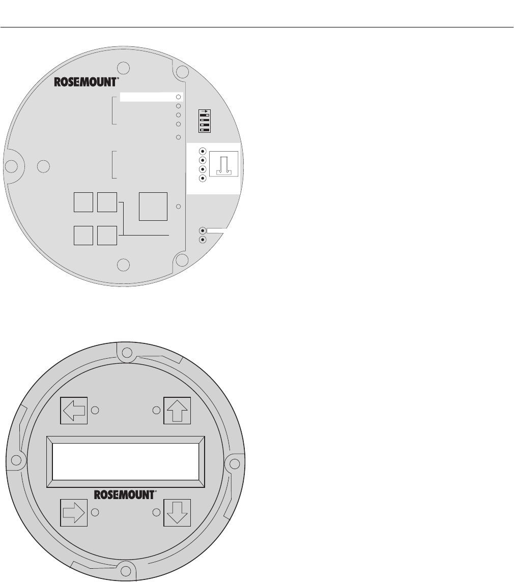
Instruction Manual
IB-106-340C Rev. 4.1
July 2004
Rosemount Analytical Inc. A Division of Emerson Process Management Troubleshooting 8-7
Hazardous Area Oxymitter 4000
DIAGNOSTIC
ALARMS
TEST
POINTS
HEATER T/C
HEATER
O2 CELL
CALIBRATION
CALIBRATION RECOMMENDED
O2 CELL mV +
O2 CELL mv -
HEATER T/C +
HEATER T/C -
INC INC
DEC DEC
HIGH
GAS
LOW
GAS
CAL
TEST GAS +
PROCESS -
% O2
SW2
TP1 J1
TP2
TP3
RED
YEL
GRN
ORG
TP4
TP5
TP6
ON
37260021
Alarms
O2 T/C Reversed
LOI
KEYPAD
Figure 8-5. Fault 3, Reversed Thermocouple
c. Fault 3, Reversed Thermocouple Wiring
or Faulty PC Board
Figure 8-5 shows the electronic assembly
for a Hazardous Area Oxymitter 4000 with
a membrane keypad (upper view) and a
Hazardous Area Oxymitter 4000 with an
LOI (lower view). The upper view also
shows J1 and test points TP1 through TP6,
located on the microprocessor board, below
the membrane keypad or the LOI module.
Membrane Keypad. When Fault 3 is
detected, the HEATER T/C LED flashes
three times, pauses for three seconds, and
repeats.
1. Using a multimeter, measure the volt-
age from TP3+ to TP4-. If the reading
is negative, the thermocouple wiring is
reversed.
2. Check red and yellow wires in the J1
connector for the proper placement.
3. If the wiring is correct, the fault is in
the PC board. See paragraph 9-4c,
Electronic Assembly Replacement.
LOI. When Fault 3 is detected, the LOI
displays the “O2 T/C Reversed” message.
1. Remove power. Unscrew and remove
the LOI module from the electronic
assembly.
2. Reconnect power to the Oxymitter
4000.
3. Perform the diagnostic steps 1 through
3 shown for the membrane keypad.
8
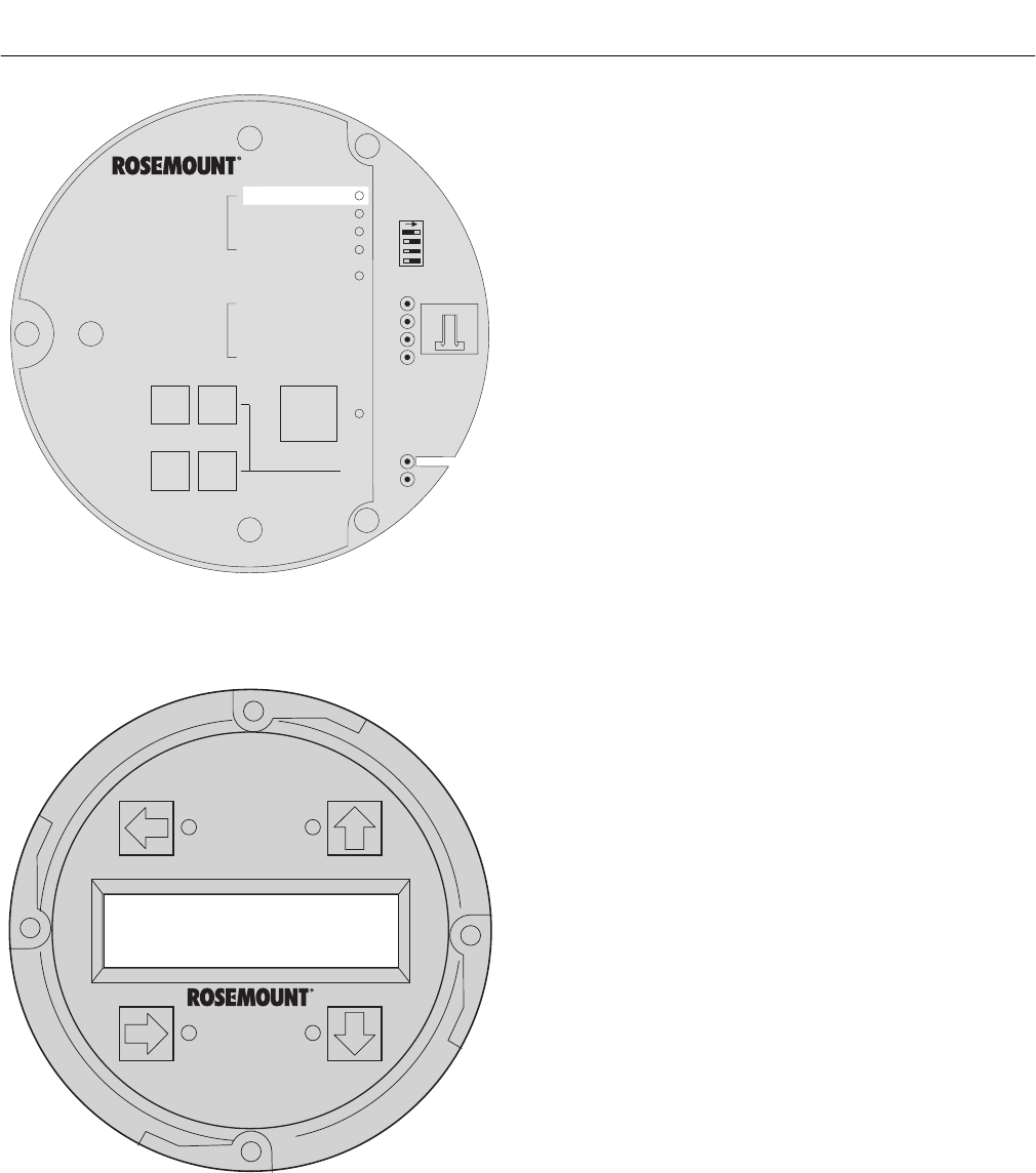
Instruction Manual
IB-106-340C Rev. 4.1
July 2004
8-8 Troubleshooting Rosemount Analytical Inc. A Division of Emerson Process Management
Hazardous Area Oxymitter 4000
DIAGNOSTIC
ALARMS
TEST
POINTS
HEATER T/C
HEATER
O2 CELL
CALIBRATION
CALIBRATION RECOMMENDED
O2 CELL mV +
O2 CELL m -
HEATER T/C +
HEATER T/C -
V
INC INC
DEC DEC
HIGH
GAS
LOW
GAS
CAL
TEST GAS +
PROCESS -
% O2
SW2
TP1 J1
TP2
TP3
RED
YEL
GRN
ORG
TP4
TP5
TP6
ON
37260022
Alarms
ADC Error
LOI
KEYPAD
Figure 8-6. Fault 4, A/D Comm Error
d. Fault 4, A/D Comm Error
Membrane Keypad. When Fault 4 is
detected, the HEATER T/C LED flashes
four times, pauses for three seconds, and
repeats (Figure 8-6).
1. Call the factory for assistance.
LOI. When Fault 4 is detected, the LOI
displays the “ADC Error” message.
1. Call the factory for assistance.

Instruction Manual
IB-106-340C Rev. 4.1
July 2004
Rosemount Analytical Inc. A Division of Emerson Process Management Troubleshooting 8-9
Hazardous Area Oxymitter 4000
LOI
KEYPAD
DIAGNOSTIC
ALARMS
TEST
POINTS
HEATER T/C
HEATER
O2 CELL
CALIBRATION
CALIBRATION RECOMMENDED
O2 CELL mV +
O2 CELL mv -
HEATER T/C +
HEATER T/C -
INC INC
DEC DEC
HIGH
GAS
LOW
GAS
CAL
TEST GAS +
PROCESS -
% O2
SW2
TP1 J1
TP2
TP3
RED
YEL
GRN
ORG
TP4
TP5
TP6
ON
37260023
Alarms
O2 Heater Open
Figure 8-7. Fault 5, Open Heater
e. Fault 5, Open Heater
Figure 8-7 shows the electronic assembly
for a Hazardous Area Oxymitter 4000 with
a membrane keypad (upper view) and a
Hazardous Area Oxymitter 4000 with an
LOI (lower view).
Membrane Keypad. When Fault 5 is
detected, the HEATER LED flashes once,
pauses for three seconds, and repeats.
1. Remove power.
2. Remove the electronic assembly per
paragraph 9-4c, Electronic Assembly
Replacement.
3. Using a multimeter, measure the re-
sistance across the terminals of heater
connector, J8.
4. The measurement should be approxi-
mately 72 ohms. If the heater is open,
see paragraph 9-4g, Heater Strut
Replacement.
LOI. When Fault 5 is detected, the LOI dis-
plays the “O2 Heater Open” message.
1. Remove power. Unscrew and remove
the LOI module from the electronic as-
sembly.
2. Perform the diagnostic steps 2 through
4 shown for the membrane keypad.
8

Instruction Manual
IB-106-340C Rev. 4.1
July 2004
8-10 Troubleshooting Rosemount Analytical Inc. A Division of Emerson Process Management
Hazardous Area Oxymitter 4000
LOI
KEYPAD
DIAGNOSTIC
ALARMS
TEST
POINTS
HEATER T/C
HEATER
O2 CELL
CALIBRATION
CALIBRATION RECOMMENDED
O2 CELL mV +
O2 CELL mv -
HEATER T/C +
HEATER T/C -
INC INC
DEC DEC
HIGH
GAS
LOW
GAS
CAL
TEST GAS +
PROCESS -
% O2
SW2
TP1 J1
TP2
TP3
RED
YEL
GRN
ORG
TP4
TP5
TP6
ON
37260024
Alarms
Very Hi O2 Temp
Figure 8-8. Fault 6, High High Heater Temp
f. Fault 6, High High Heater Temp
Figure 8-8 shows the electronic assembly
for a Hazardous Area Oxymitter 4000 with
a membrane keypad (upper view) and a
Hazardous Area Oxymitter 4000 with an
LOI (lower view).
Membrane Keypad. When Fault 6 is
detected, the HEATER LED flashes twice,
pauses for three seconds, and repeats.
1. The high high heater temp alarm will
activate when the thermocouple pro-
duces a voltage of 37.1 mV
[900°C (1652°F)].
2. The triac and the temperature control
may be at fault.
3. Remove power. Allow Hazardous Area
Oxymitter 4000 to cool for five minutes.
Restore power.
4. If the condition repeats, replace the
electronic assembly per paragraph
9-4c.1, Electronic Assembly
Replacement.
LOI. When Fault 6 is detected, the LOI
displays the “Very Hi O2 Temp” message.
1. The very high O2 temperature alarm
will activate when the thermocouple
produces a voltage of 37.1 mV
[900°C (1652°F)].
2. The triac and the temperature control
may be at fault.
3. Remove power. Allow the Oxymitter
4000 to cool for five minutes. Restore
power.
4. If the condition repeats, replace the
electronic assembly per paragraph
9-4c, Electronic Assembly Replace-
ment.
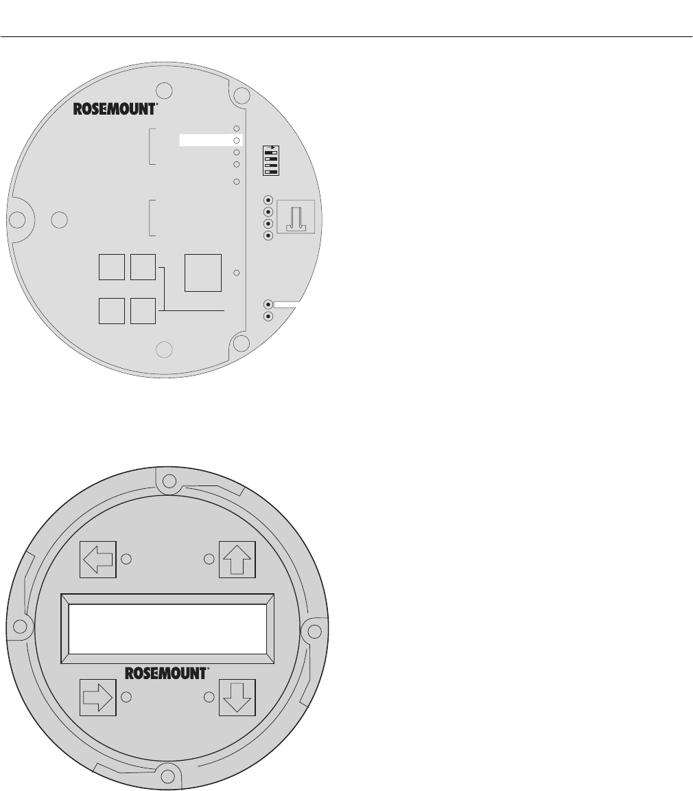
Instruction Manual
IB-106-340C Rev. 4.1
July 2004
Rosemount Analytical Inc. A Division of Emerson Process Management Troubleshooting 8-11
Hazardous Area Oxymitter 4000
LOI
KEYPAD
DIAGNOSTIC
ALARMS
TEST
POINTS
HEATER T/C
HEATER
O2 CELL
CALIBRATION
CALIBRATION RECOMMENDED
O2 CELL mV +
O2 CELL mv -
HEATER T/C +
HEATER T/C -
INC INC
DEC DEC
HIGH
GAS
LOW
GAS
CAL
TEST GAS +
PROCESS -
% O2
SW2
TP1 J1
TP2
TP3
RED
YEL
GRN
ORG
TP4
TP5
TP6
ON
37260025
Alarms
Board Temp Hi
Figure 8-9. Fault 7, High Case Temp
g. Fault 7, High Case Temp
Figure 8-9 shows the electronic assembly
for a Hazardous Area Oxymitter 4000 with
a membrane keypad (upper view) and a
Hazardous Area Oxymitter 4000 with an
LOI (lower view).
Membrane Keypad. When Fault 7 is
detected, The HEATER LED flashes three
times, pauses for three seconds, and
repeats.
1. If the case temperature exceeds 85°C
(185°F), the temperature control will
shut off and the 4-20 mA signal output
will go to the default value.
2. This signifies that the environment
where the Hazardous Area Oxymitter
4000 is installed exceeds the ambient
temperature requirements or that heat
due to convection is causing case tem-
perature to rise above the limit.
3. Placing a spool piece between the
stack flange and the Hazardous Area
Oxymitter 4000 flange may eliminate
this problem.
4. If a spool piece does not solve the
problem, relocation is the only solution.
LOI. When Fault 7 is detected, the LOI
displays the “Board Temp Hi” message.
Refer to the comments in paragraphs 1
through 4 above.
8

Instruction Manual
IB-106-340C Rev. 4.1
July 2004
8-12 Troubleshooting Rosemount Analytical Inc. A Division of Emerson Process Management
Hazardous Area Oxymitter 4000
LOI
KEYPAD
DIAGNOSTIC
ALARMS
TEST
POINTS
HEATER T/C
HEATER
O2 CELL
CALIBRATION
CALIBRATION RECOMMENDED
O2 CELL mV +
O2 CELL mv -
HEATER T/C +
HEATER T/C -
INC INC
DEC DEC
HIGH
GAS
LOW
GAS
CAL
TEST GAS +
PROCESS -
% O2
SW2
TP1 J1
TP2
TP3
RED
YEL
GRN
ORG
TP4
TP5
TP6
ON
37260026
Alarms
O2 Temp Low
Figure 8-10. Fault 8, Low Heater Temp
h. Fault 8, Low Heater Temp
Figure 8-10 shows the electronic assembly
for a Hazardous Area Oxymitter 4000 with
a membrane keypad (upper view) and a
Hazardous Area Oxymitter 4000 with an
LOI (lower view).
Membrane Keypad. When Fault 8 is
detected, the HEATER LED flashes four
times, pauses for three seconds, and
repeats.
1. The low heater temperature alarm is
active when the thermocouple reading
has dropped below 28.6 mV.
2. If the thermocouple reading continues
to ramp downward for one minute and
does not return to the temperature set
point of approximately 29.3 mV, then
an Open Heater fault will be displayed.
3. Power down the electronics. Remove
the electronic assembly per paragraph
9-4c, Electronic Assembly Replace-
ment. Using a multimeter, measure the
resistance across the terminals of
heater connector, J8.
4. If the heater is good, the reading will be
approximately 70 ohms. If the heater is
open, see paragraph 9-4g, Heater Strut
Replacement.
LOI. When Fault 8 is detected, the LOI
displays the “O2 Temp Low” message.
Refer to the comments and procedures in
paragraphs 1 through 4 above.

Instruction Manual
IB-106-340C Rev. 4.1
July 2004
Rosemount Analytical Inc. A Division of Emerson Process Management Troubleshooting 8-13
Hazardous Area Oxymitter 4000
Alarms
O2 Temp Hi
LOI
KEYPAD
DIAGNOSTIC
ALARMS
TEST
POINTS
HEATER T/C
HEATER
O2 CELL
CALIBRATION
CALIBRATION RECOMMENDED
O2 CELL mV +
O2 CELL mv -
HEATER T/C +
HEATER T/C -
INC INC
DEC DEC
HIGH
GAS
LOW
GAS
CAL
TEST GAS +
PROCESS -
% O2
SW2
TP1 J1
TP2
TP3
RED
YEL
GRN
ORG
TP4
TP5
TP6
ON
37260027
Figure 8-11. Fault 9, High Heater Temp
i. Fault 9, High Heater Temp
Figure 8-11 shows the electronic assembly
for a Hazardous Area Oxymitter 4000 with
a membrane keypad (upper view) and a
Hazardous Area Oxymitter 4000 with an
LOI (lower view).
Membrane Keypad. When Fault 9 is
detected, the HEATER LED flashes five
times, pauses for three seconds, and
repeats.
1. If the thermocouple produces a voltage
in excess of approximately 30.7 mV,
the high heater temp alarm activates.
2. The 4-20 mA signal returns to the
default value (4 or 20 mA).
3. This alarm is self-clearing. When tem-
perature control is restored and the
thermocouple voltage returns to the
normal range, the alarm clears.
4. If the temperature continues to rise, the
next alarm will be the high high heater
temp alarm.
LOI. When Fault 9 is detected, the LOI
displays the “O2 Temp Hi” message. Refer
to the comments and procedures in para-
graphs 1 through 4 above.
8
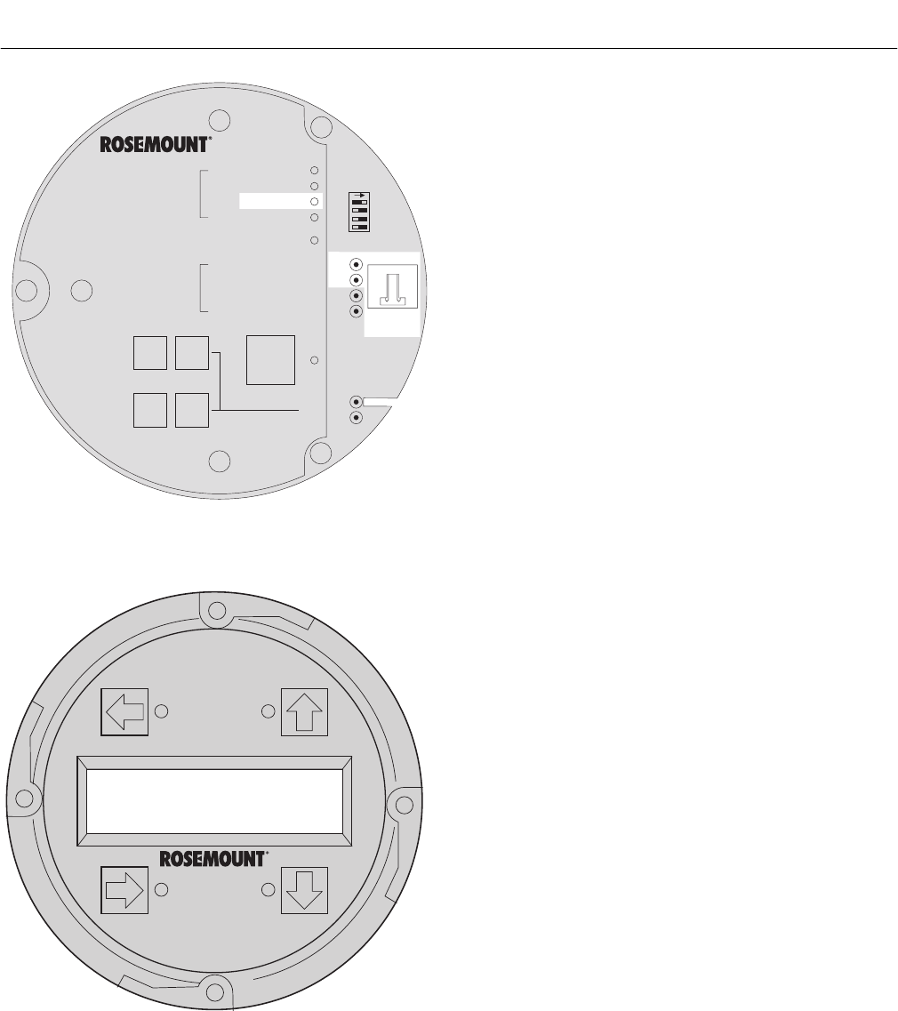
Instruction Manual
IB-106-340C Rev. 4.1
July 2004
8-14 Troubleshooting Rosemount Analytical Inc. A Division of Emerson Process Management
Hazardous Area Oxymitter 4000
Alarms
O2 Cell Open
LOI
KEYPAD
DIAGNOSTIC
ALARMS
TEST
POINTS
HEATER T/C
HEATER
O2 CELL
CALIBRATION
CALIBRATION RECOMMENDED
O2 CELL mV +
O2 CELL mv -
HEATER T/C +
HEATER T/C -
INC INC
DEC DEC
HIGH
GAS
LOW
GAS
CAL
TEST GAS +
PROCESS -
% O2
SW2
TP1 J1
TP2
TP3
RED
YEL
GRN
ORG
TP4
TP5
TP6
ON
37260028
Figure 8-12. Fault 10, High Cell mV
j. Fault 10, High Cell mV
Figure 8-12 shows the electronic assembly
for a Hazardous Area Oxymitter 4000 with
a membrane keypad (upper view) and a
Hazardous Area Oxymitter 4000 with an
LOI (lower view). The upper view also
shows J1 and test points TP1 through TP6,
located on the microprocessor board, below
the membrane keypad or the LOI module.
Membrane Keypad. When Fault 10 is
detected, the O2 CELL flashes once,
pauses for three seconds, and repeats.
1. Using a multimeter, measure across
TP1+ to TP2-. If you measure 204 mV
to 1 volt DC, the cell reading is due to
high combustibles. This is a self-
clearing alarm, once the combustible
conditions go away. If you measure
1.2 VDC, the cell wires, either orange
or green, have become detached from
the input.
2. One possible cause is connector J1.
The orange or green wire has come
loose from the crimped connection.
3. The platinum pad could also be at fault.
The pad could have broken free from
the back of the cell.
4. Replace heater strut per paragraph
9-4g, Heater Strut Replacement. If
necessary, replace the cell and flange
assembly per paragraph 9-4h, Cell
Replacement.
LOI. When Fault 10 is detected, the LOI
displays the “O2 Cell Open” message.
1. Remove power. Unscrew and remove
the LOI module from the electronic
assembly.
2. Reconnect power to the Oxymitter
4000.
3. Perform the diagnostic steps 1 through
4 shown for the membrane keypad.
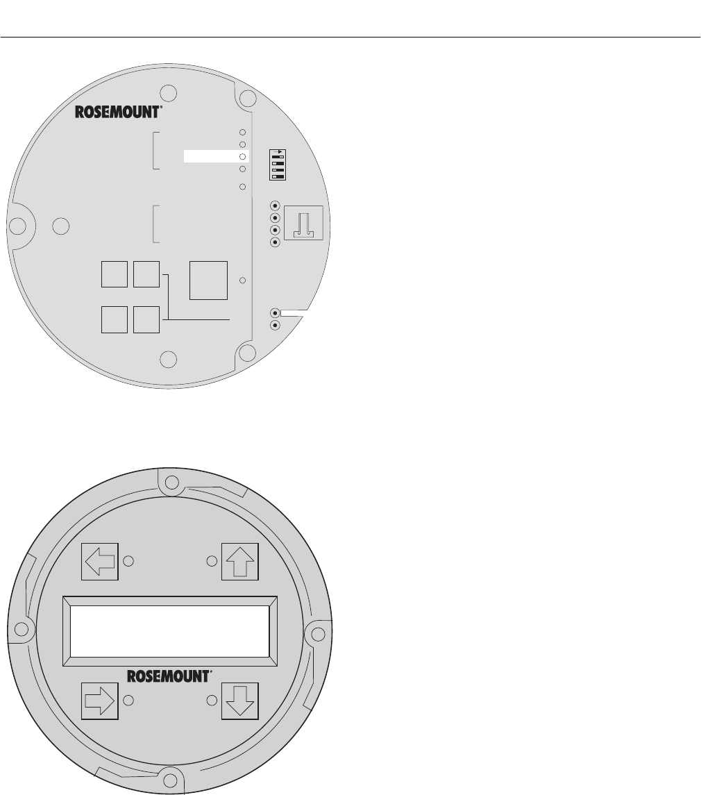
Instruction Manual
IB-106-340C Rev. 4.1
July 2004
Rosemount Analytical Inc. A Division of Emerson Process Management Troubleshooting 8-15
Hazardous Area Oxymitter 4000
Alarms
O2 Cell Bad
LOI
KEYPAD
DIAGNOSTIC
ALARMS
TEST
POINTS
HEATER T/C
HEATER
O2 CELL
CALIBRATION
CALIBRATION RECOMMENDED
O2 CELL mV +
O2 CELL mv -
HEATER T/C +
HEATER T/C -
INC INC
DEC DEC
HIGH
GAS
LOW
GAS
CAL
TEST GAS +
PROCESS -
% O2
SW2
TP1 J1
TP2
TP3
RED
YEL
GRN
ORG
TP4
TP5
TP6
ON
37260029
Figure 8-13. Fault 11, Bad Cell
k. Fault 11, Bad Cell
Figure 8-13 shows the electronic assembly
for a Hazardous Area Oxymitter 4000 with
a membrane keypad (upper view) and a
Hazardous Area Oxymitter 4000 with an
LOI (lower view).
Membrane Keypad. When Fault 11 is
detected, the O2 CELL flashes three times,
pauses for three seconds, and repeats.
1. The bad cell alarm activates when the
cell exceeds the maximum resistance
value.
2. The cell should be replaced. See para-
graph 9-4h, Cell Replacement, for cell
replacement instructions.
LOI. When Fault 11 is detected, the LOI
displays the “O2 Cell Bad” message. Refer
to the comments and procedures in para-
graphs 1 and 2 above.
8
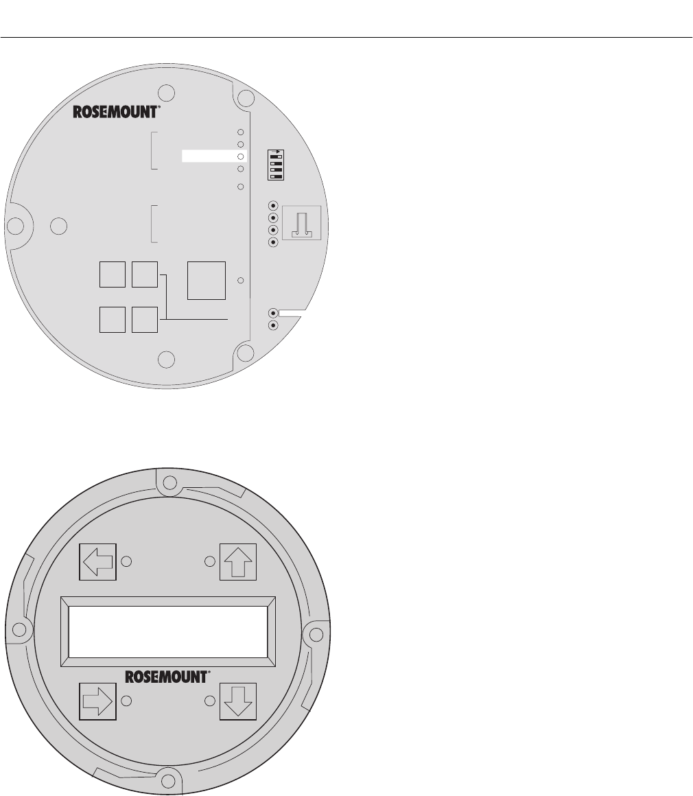
Instruction Manual
IB-106-340C Rev. 4.1
July 2004
8-16 Troubleshooting Rosemount Analytical Inc. A Division of Emerson Process Management
Hazardous Area Oxymitter 4000
Alarms
O2 Cell Bad
LOI
KEYPAD
DIAGNOSTIC
ALARMS
TEST
POINTS
HEATER T/C
HEATER
O2 CELL
CALIBRATION
CALIBRATION RECOMMENDED
O2 CELL mV +
O2 CELL mv -
HEATER T/C +
HEATER T/C -
INC INC
DEC DEC
HIGH
GAS
LOW
GAS
CAL
TEST GAS +
PROCESS -
% O2
SW2
TP1 J1
TP2
TP3
RED
YEL
GRN
ORG
TP4
TP5
TP6
ON
37260029
Figure 8-14. Fault 12, EEprom Corrupt
l. Fault 12, EEprom Corrupt
Figure 8-14 shows the electronic assembly
for a Hazardous Area Oxymitter 4000 with
a membrane keypad (upper view) and a
Hazardous Area Oxymitter 4000 with an
LOI (lower view).
Membrane Keypad. When Fault 12 is
detected, the O2 CELL LED flashes four
times, pauses for three seconds, and
repeats.
1. This alarm can occur if the EEprom is
changed for a later version. At power
up, the EEprom is not updated.
2. To correct this problem, power down
and then restore power. The alarm
should clear.
3. If the alarm occurs while the unit is
running, there is a hardware problem
on the microprocessor board.
4. If cycling the power does not clear the
alarm, see paragraph 9-4c, Electronic
Assembly Replacement.
LOI. When Fault 12 is detected, the LOI
displays the “EEprom Corrupt” message.
Refer to the comments and procedures in
paragraphs 1 through 4 above.
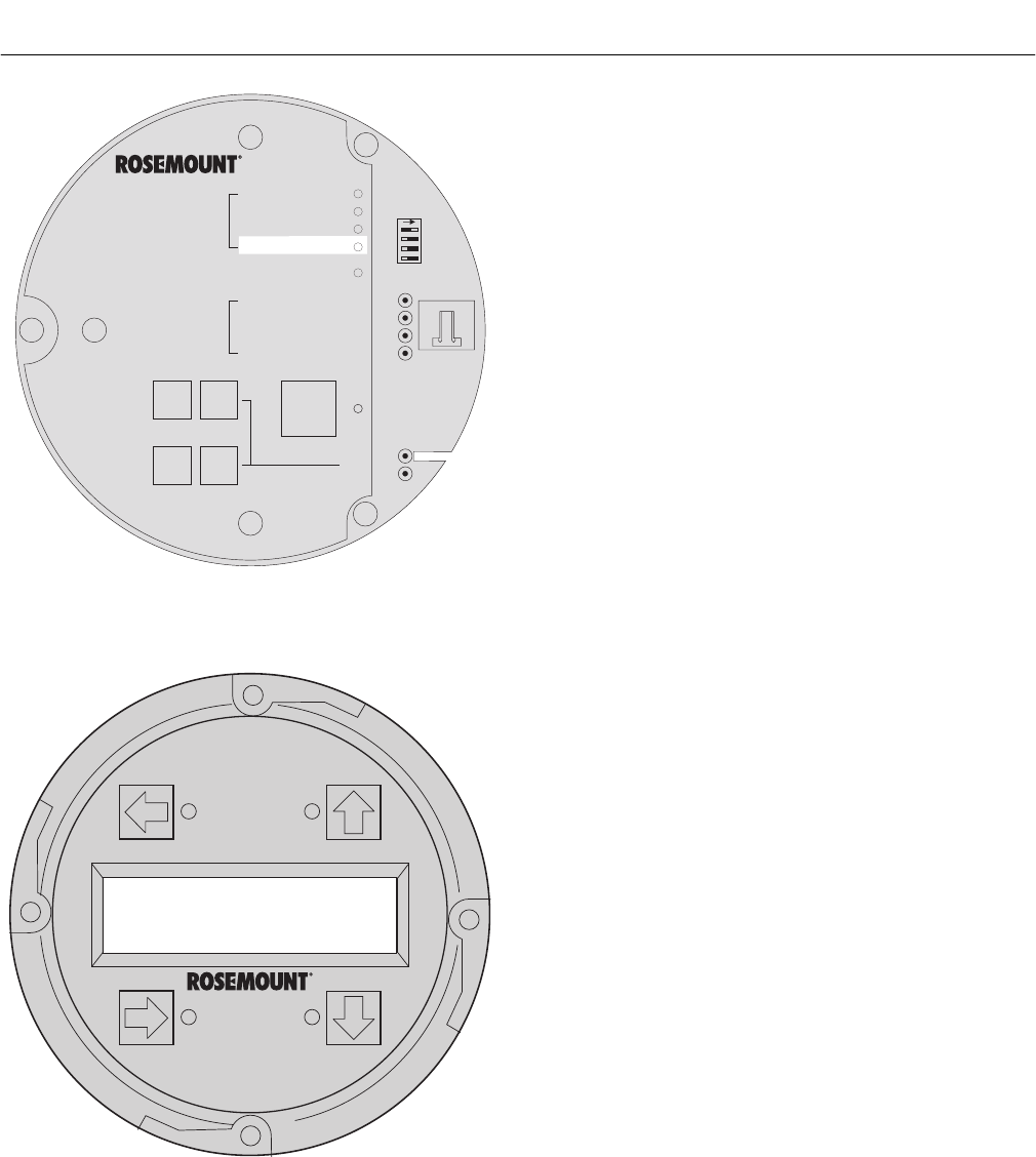
Instruction Manual
IB-106-340C Rev. 4.1
July 2004
Rosemount Analytical Inc. A Division of Emerson Process Management Troubleshooting 8-17
Hazardous Area Oxymitter 4000
DIAGNOSTIC
ALARMS
TEST
POINTS
HEATER T/C
HEATER
O2 CELL
CALIBRATION
CALIBRATION RECOMMENDED
O2 CELL mV +
O2 CELL mv -
HEATER T/C +
HEATER T/C -
INC INC
DEC DEC
HIGH
GAS
LOW
GAS
CAL
TEST GAS +
PROCESS -
% O2
SW2
TP1 J1
TP2
TP3
RED
YEL
GRN
ORG
TP4
TP5
TP6
ON
37260031
Alarms
O2 Cell Bad
LOI
KEYPAD
Figure 8-15. Fault 13, Invalid Slope
m. Fault 13, Invalid Slope
Figure 8-15 shows the electronic assembly
for a Hazardous Area Oxymitter 4000 with
a membrane keypad (upper view) and a
Hazardous Area Oxymitter 4000 with an
LOI (lower view).
Membrane Keypad. When Fault 13 is
detected, the CALIBRATION LED flashes
once, pauses for three seconds, and
repeats.
1. During a calibration, the electronics
calculates a slope value. If the value
of the slope is less than 35 mV/dec or
more than 52 mV/dec, the slope alarm
will be active until the end of the purge
cycle.
2. See paragraph 9-2, Calibration. Verify
the calibration by carefully repeating it.
Ensure the calibration gases match
the calibration gas parameters. If you
attach a multimeter to TP1+ and TP2-,
sample gas measurements are:
8% O2 ≈ 23 mV
0.4% O2 ≈ 85 mV
3. Power down the Hazardous Area
Oxymitter 4000 and remove it from
the stack.
4. Replace the cell per paragraph 9-4h,
Cell Replacement.
LOI. When Fault 13 is detected, the LOI
displays the “O2 Cell Bad” message. Refer
to the comments and procedures in para-
graphs 1 through 4 above.
8
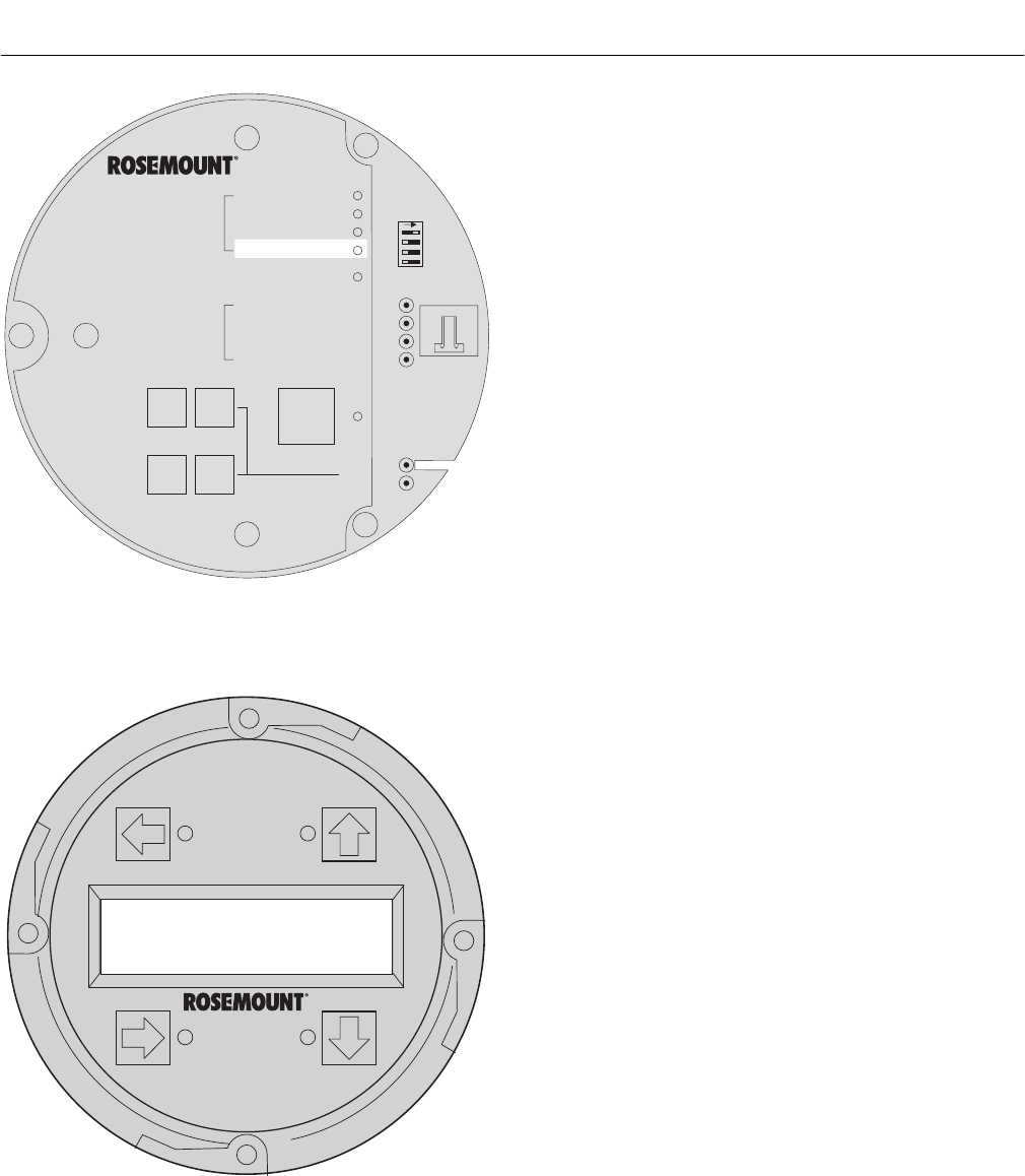
Instruction Manual
IB-106-340C Rev. 4.1
July 2004
8-18 Troubleshooting Rosemount Analytical Inc. A Division of Emerson Process Management
Hazardous Area Oxymitter 4000
DIAGNOSTIC
ALARMS
TEST
POINTS
HEATER T/C
HEATER
O2 CELL
CALIBRATION
CALIBRATION RECOMMENDED
O2 CELL mV +
O2 CELL mv -
HEATER T/C +
HEATER T/C -
INC INC
DEC DEC
HIGH
GAS
LOW
GAS
CAL
TEST GAS +
PROCESS -
% O2
SW2
TP1 J1
TP2
TP3
RED
YEL
GRN
ORG
TP4
TP5
TP6
ON
37260032
Alarms
O2 Cell Bad
LOI
KEYPAD
Figure 8-16. Fault 14, Invalid Constant
n. Fault 14, Invalid Constant
Figure 8-16 shows the electronic assembly
for a Hazardous Area Oxymitter 4000 with
a membrane keypad (upper view) and a
Hazardous Area Oxymitter 4000 with an
LOI (lower view).
Membrane Keypad. When Fault 14 is
detected, the CALIBRATION LED flashes
twice, pauses for three seconds, and
repeats.
1. After a calibration has been performed,
the electronics calculates a cell con-
stant value.
2. If the cell constant value is outside of
the range, -4 mV to 10 mV, the alarm
will activate. See paragraph 9-2, Cali-
bration, and verify the last calibration
was performed correctly.
3. Power down the Hazardous Area
Oxymitter 4000 and remove it from the
stack.
4. Replace the cell per paragraph 9-4h,
Cell Replacement.
LOI. When Fault 14 is detected, the LOI
displays the “O2 Cell Bad” message. Refer
to the comments and procedures in para-
graphs 1 through 4 above.

Instruction Manual
IB-106-340C Rev. 4.1
July 2004
Rosemount Analytical Inc. A Division of Emerson Process Management Troubleshooting 8-19
Hazardous Area Oxymitter 4000
DIAGNOSTIC
ALARMS
TEST
POINTS
HEATER T/C
HEATER
O2 CELL
CALIBRATION
CALIBRATION RECOMMENDED
O2 CELL mV +
O2 CELL mv -
HEATER T/C +
HEATER T/C -
INC INC
DEC DEC
HIGH
GAS
LOW
GAS
CAL
TEST GAS +
PROCESS -
% O2
SW2
TP1 J1
TP2
TP3
RED
YEL
GRN
ORG
TP4
TP5
TP6
ON
37260033
Alarms
Calib Failed
LOI
KEYPAD
Figure 8-17. Fault 15, Last Calibration Failed
o. Fault 15, Last Calibration Failed
Figure 8-17 shows the electronic assembly
for a Hazardous Area Oxymitter 4000 with
a membrane keypad (upper view) and a
Hazardous Area Oxymitter 4000 with an
LOI (lower view).
Membrane Keypad. When Fault 15 is
detected, the CALIBRATION LED flashes
three times, pauses for three seconds, and
repeats.
1. The last calibration failed alarm acti-
vates when the slope and constant
values calculated are out of range and
the unit reverts to using the previous
calibration values.
2. The cell should be replaced. See para-
graph 9-4h, Cell Replacement, for cell
replacement instructions.
LOI. When Fault 15 is detected, the LOI
displays the “Calib Failed” message. Refer
to the comments in paragraphs 1 and 2
above.
8
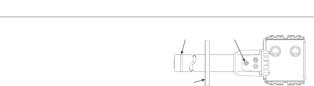
Instruction Manual
IB-106-340C Rev. 4.1
July 2004
8-20 Troubleshooting Rosemount Analytical Inc. A Division of Emerson Process Management
Hazardous Area Oxymitter 4000
8-6 HAZARDOUS AREA OXYMITTER 4000
PASSES CALIBRATION, BUT STILL
READS INCORRECTLY
There are a few fault conditions where no alarm
indication is present and the probe passes cali-
bration, but the O2 reading may still be incorrect:
a. Probe passes calibration, but still ap-
pears to read high.
1. There may be a leak that is permitting
ambient air to mix with the process
gases. Since many combustion proc-
esses are slightly negative in pressure,
ambient air can be sucked into the cell
area, biasing the O2 reading upward.
(a) Make sure that the calibration gas
line is capped tightly between cali-
brations. If autocal is used, make
sure the check valve is seating
properly.
(b) If an abrasive shield is installed
to protect the entire probe from
particulate erosion, a leak in the
probe flange gasket can allow
ambient air to migrate down the
annular space between the probe
and shield, and then into the cell.
Always install a new probe flange
gasket when re-installing a probe.
2. There may be a leak inside the probe
itself, permitting the reference air
(20.95% O2) to mix with the process
gases at the cell. To confirm this leak
condition, instrument air will need to be
connected for reference. Pressurize
the inside (reference side) of the probe
by plugging the reference air exhaust
port with your finger for 1 minute. The
O2 reading should decrease slightly. If
the O2 reading increases during this
test, there is a leak inside the probe.
(a) Acid condensation inside the probe
can degrade the red silicon tube
(item 38, Figure 9-3) that carries the
cal gas to the cell. Remove the
housing (11) to inspect this hose.
(See Section 9, MAINTENANCE
AND SERVICE).
BOTTOM VIEW
37260045
PROBE HEAD
CORRUGATED
SEAL
REFERENCE AIR
EXHAUST PORT
PROBE
FLANGE
GASKET
Figure 8-18. Probe Leakage Paths
(b) The sensing cell is bolted to the
end of the probe, and uses a cor-
rugated metallicseal (item 25,
Figure 9-3) to separate the process
gases from the ambient reference
air. This seal can be used only one
time, so always replace this seal
when a cell is replaced. Always
apply anti-seize compound on both
sides of the corrugations.
b. Probe passes calibration, but still
appears to read low.
The diffusion element at the end of the
probe is a passive filter. It plugs very slowly,
since there is no active flow being drawn
across it. In applications that have a heavy
particulate loading (coal or wood fired boil-
ers, cement and lime kilns, catalyst regen-
eration, recovery boilers, etc.), this diffusion
element will eventually plug.
It is important not to pressurize the sensing
cell during calibrations by flowing excessive
cal gas against a plugged diffuser. Calibra-
tion flow rates should be set only when a
new diffuser is installed. As the diffuser
plugs, do not adjust the flow rates upward.
How do I detect a plugged diffuser?
1. The O2 signal's speed of response will
degrade. The O2 trend in the control
room will become smoother.
2. When calibrating, the calibration gas
flow rate will be noted to be lower.
Never readjust this flow upwards.
Adjust this flow only when a new
diffuser is installed.

Instruction Manual
IB-106-340C Rev. 4.1
July 2004
Rosemount Analytical Inc. A Division of Emerson Process Management Troubleshooting 8-21
Hazardous Area Oxymitter 4000
3. Always note the time it takes for the
cell to recover to the normal process
value after the cal gas is removed. As
the diffuser plugs, this recovery time
will get longer and longer. Use the
Calibration Record form provided in
this manual.
Can I calibrate a badly plugged diffuser?
1. It may not be possible to immediately
replace a plugged diffuser while the
process is on line.
2. One can calibrate the probe without
pressurizing the cell by adjusting the
calibration gas flow rate downward
before calibration. For instance, say
the process is at 3%, and the first
calibration gas is 8%. Adjust the flow
of cal gas downward until the reading
begins to migrate from 8% to lower
values, indicating that process gases
are now mixing in with the calibration
gases.
3. Adjust the flow rate back up until this
mixing is just eliminated. Calibrate at
this flow rate. Replace the diffuser at
the first opportunity.
8

Instruction Manual
IB-106-340C Rev. 4.1
July 2004
9-0 Maintenance and Service Rosemount Analytical Inc. A Division of Emerson Process Management
Hazardous Area Oxymitter 4000
Calibration Record
For
Rosemount Analytical In Situ O2 Probe
Probe Serial Number:
Probe Tag Number:
Probe Location:
Date Placed Into Service:
Date Slope Constant Impedance Responseinitial Responsefinal
Notes: Responseinitial When the second calibration gas is turned off, note the number of seconds required for
the O2 value to begin migrating back to the process value.
Responsefinal When the second calibration gas is turned off, note the number of seconds required for
the O2 value to settle out at the process value.
Instruction Manual
IB-106-340C Rev. 4.1
July 2004
Rosemount Analytical Inc. A Division of Emerson Process Management Maintenance and Service 9-1
Hazardous Area Oxymitter 4000
SECTION 9
MAINTENANCE AND SERVICE
9-1 OVERVIEW
This section identifies the calibration methods
available and provides the procedures to main-
tain and service the Hazardous Area Oxymitter
4000.
When working on this equipment on
the laboratory bench, be aware that
the Hazardous Area Oxymitter 4000,
probe tube, and flame arrestor hub
can be hot [up to 300°C (572°F)] in the
region of the probe heater.
Install all protective equipment covers
and safety ground leads after equip-
ment repair or service. Failure to in-
stall covers and ground leads could
result in serious injury or death.
9-2 CALIBRATION – HAZARDOUS AREA
OXYMITTER 4000 WITH KEYPAD
a. During a calibration, two calibration gases
with known O2 concentrations are applied
to the Hazardous Area Oxymitter 4000.
Slope and constant values calculated from
the two calibration gases determine if the
Hazardous Area Oxymitter 4000 is correctly
measuring the net concentration of O2 in
the industrial process. A calibration record
sheet is provided on the previous page. Use
photocopies of the calibration record sheet
to track transmitter performance.
Before calibrating the Hazardous Area
Oxymitter 4000, verify that the calibration
gas parameters are correct by setting the
gas concentrations (See paragraph 5-2a.5
or 6-5.) used when calibrating the unit and
by setting the calibration gas flowmeter.
The calibration gas flowmeter regulates the
calibration gas flow and must be set to 5
scfh. However, only adjust the flowmeter to
5 scfh after placing a new diffuser on the
end of the probe. Adjusting the flowmeter at
any other time can pressurize the cell and
bias the calibration.
In applications with a heavy dust loading,
the O2 probe diffusion element may become
plugged over time, causing a slower speed
of response. The best way to detect a
plugged diffusion element is to note the time
it takes the Hazardous Area Oxymitter 4000
to return to the normal process reading after
the last calibration gas is removed and the
calibration gas line is blocked off. A plugged
diffusion element also can be indicated by a
slightly lower reading on the flowmeter.
Change the diffusion element when the
calibration gas flowmeter reads slightly
lower during calibration or when response
to the process flue gases becomes very
slow. Each time the diffusion element is
changed, reset the calibration gas flowme-
ter to 5 scfh and calibrate the Hazardous
Area Oxymitter 4000. To change the diffu-
sion element, refer to paragraph 9-4i.
b. Three types of calibration methods are
available: automatic, semi-automatic, and
manual.
NOTE
A calibration can be aborted any time
during the process. Press the CAL key
(Figure 9-1) on the Hazardous Area
Oxymitter 4000 keypad three times
within three seconds, or abort via the
LOI, HART/AMS, or an IMPS 4000. An
aborted calibration will retain the values
of the previous good calibration.
9
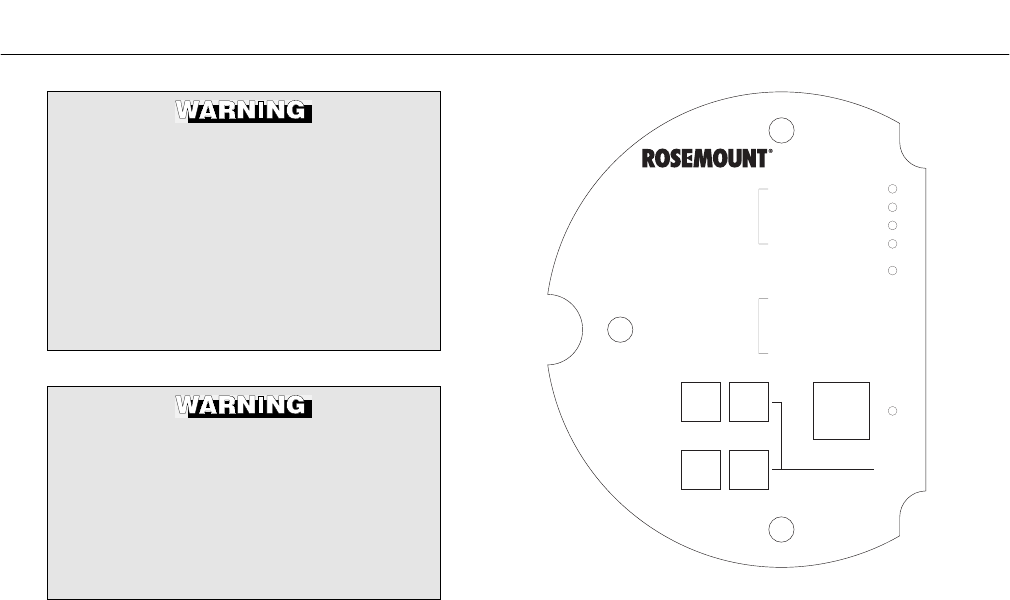
Instruction Manual
IB-106-340C Rev. 4.1
July 2004
9-2 Maintenance and Service Rosemount Analytical Inc. A Division of Emerson Process Management
Hazardous Area Oxymitter 4000
The HART option is not protected by
energy limiting barriers. It must not be
interfaced from within the hazardous
area. The 4-20 mA cables should be
routed and the connections made out-
side the hazardous area. Note that
this is the case even when using the
intrinsically safe version of the hand-
held communicator.
Do not install an IMPS 4000 or SPS
4000 within the hazardous area.
Installing the unit in a potentially
explosive environment could cause
serious injury or death and equipment
damage. Ensure the sequencer is
installed in a safe area.
1. Automatic Calibration. Automatic
calibrations require no operator action.
However, the calibration gases must
be permanently piped to the Hazard-
ous Area Oxymitter 4000, an SPS
4000 or IMPS 4000 must be installed
to sequence the gases, and the logic
I/O must be set to mode 8 via
HART/AMS so the sequencer and
Hazardous Area Oxymitter 4000 can
communicate.
Depending on your system setup, an
automatic calibration can be initiated
by the following methods:
(a) The Hazardous Area Oxymitter
4000’s CALIBRATION RECOM-
MENDED alarm signals that a
calibration is required.
(b) Use the HART/AMS or the LOI to
enter a “time since last cal” (CAL
INTRVL) parameter that will initiate
an automatic calibration at a
scheduled time interval (in hours).
To configure the CAL INTRVL
parameter, refer to paragraph 7-8
for the HART/AMS, or paragraph
6-5 for the LOI.
DIAGNOSTIC
ALARMS
TEST
POINTS
HEATER T/C
HEATER
O2 CELL
CALIBRATION
CALIBRATION RECOMMENDED
O2 CELL mV +
O2 CELL mv -
HEATER T/C +
HEATER T/C -
INC INC
DEC DEC
HIGH
GAS
LOW
GAS
CAL
TEST GAS +
PROCESS -
% O2
22220067
Figure 9-1. Membrane Keypad
(c) If using an IMPS 4000, enter a
time interval via the IMPS 4000
keypad that will initiate an auto-
matic calibration at a scheduled
time interval (in hours). To set the
CalIntvX parameter of the
CHANGE PRESETS display
mode, refer to the IMPS 4000
Intelligent Multiprobe Test Gas
Sequencer Instruction Bulletin for
more information.
Once an automatic calibration is initi-
ated, by any of the methods previously
described, the Hazardous Area Oxy-
mitter 4000’s CALIBRATION REC-
OMMENDED alarm signals an IMPS
4000 or SPS 4000 to initiate a calibra-
tion. The sequencer sends an “in cal”
signal to the control room so that any
automatic control loops can be placed
in manual. Then, the sequencer begins
to sequence the calibration gases.

Instruction Manual
IB-106-340C Rev. 4.1
July 2004
Rosemount Analytical Inc. A Division of Emerson Process Management Maintenance and Service 9-3
Hazardous Area Oxymitter 4000
2. Semi-Automatic Calibration. Semi-
automatic calibrations only require
operator initiation. However, the cali-
bration gases must be permanently
piped to the Hazardous Area Oxymitter
4000, an SPS 4000 or IMPS 4000
must be installed to sequence the
gases, and the logic I/O must be set
to mode 8 or 9 via HART/AMS to allow
the sequencer and the Hazardous Area
Oxymitter 4000 to communicate.
Depending on your system setup,
a semi-automatic calibration can be
initiated by the following methods:
(a) Hazardous Area Oxymitter 4000
with membrane keypad. Press the
CAL key on the Hazardous Area
Oxymitter 4000 keypad.
(b) Hazardous Area Oxymitter 4000
with LOI. Select “Start Calib” from
the CALIBRATION menu.
(c) IMPS 4000. Use the IMPS 4000
keypad to change the InitCalX
parameter of the CHANGE PRE-
SETS display mode from 0000 to
0001. Refer to the IMPS 4000
Intelligent Multiprobe Test Gas
Sequencer Instruction Bulletin for
more information.
(d) HART. Use the HART Communi-
cator to access the O2 CALIBRATE
menu and perform the O2 CAL
method. Refer to paragraph 7-7 for
the complete calibration procedure.
(e) AMS. Refer to AMS documentation
for more information.
(f) Remote Contact. Initiate a calibra-
tion from a remote location via the
remote contact input connection
provided by an IMPS 4000 or SPS
4000. Refer to the documentation
available for the control system in
use for more information.
Once a semi-automatic calibration is
initiated by any of the methods previ-
ously described, the Hazardous Area
Oxymitter 4000’s CALIBRATION
RECOMMENDED alarm signals an
IMPS 4000 or SPS 4000 to initiate a
calibration. The sequencer sends an
“in cal” signal to the control room so
that any automatic control loops can be
placed in manual. Then, the sequencer
begins to sequence the calibration
gases.
3. Manual Calibration with Membrane
Keypad. Manual calibrations must be
performed at the Hazardous Area
Oxymitter 4000 site and will require
operator intervention throughout the
process. Manual calibration instruc-
tions, in condensed form, can also be
found on the inside of the right elec-
tronics housing cover. See Figure 9-2.
Use the following procedure to perform
a manual calibration:
(a) Place control loop in manual.
(b) Verify the calibration gas parame-
ters are correct per paragraph
9-2a.
(c) If performing a manual calibration
with the CALIBRATION RECOM-
MENDED LED off and the CAL
LED off, start at step 1.
(d) If performing a manual calibration
with the CALIBRATION RECOM-
MENDED LED on and the CAL
LED on, start at step 2.
1 Push the CAL key. The CALI-
BRATION RECOMMENDED
LED will come on and the
CAL LED will be on solid. If a
multimeter is attached across
TP5 and TP6, the reading will
display the percentage of
oxygen seen by the cell.
9
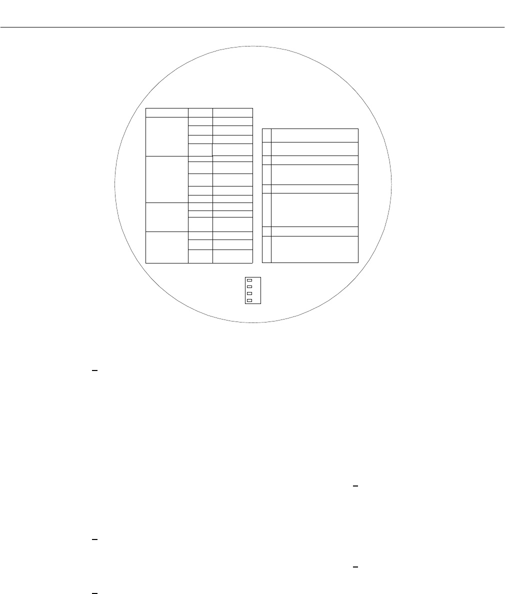
Instruction Manual
IB-106-340C Rev. 4.1
July 2004
9-4 Maintenance and Service Rosemount Analytical Inc. A Division of Emerson Process Management
Hazardous Area Oxymitter 4000
SW2 DIP SWITCH
HART LOCAL
0-10% 0-25%
4mA 20mA
NOT USED
NOT USED
LED
HEATER
O2 CELL
CALIBRATION
HEATER T/C
STATUS
OPEN
SHORTED
REVERSED
HIGH HIGH
TEMP
HIGH CASE
TEMP
LOW TEMP
HIGH TEMP
OPEN
BAD
EPROM
CORRUPT
INVALID SLOPE
INVALID
CONSTANT
FLASHES
1
2
3
4
1
2
OPEN
3
4
5
1
3
4
1
2
PUSH CAL
CAL LED ON
APPLY TG1
PUSH CAL
CAL LED ON SOLID
REMOVE TG1 & APPLY TG2
PUSH CAL
CAL LED ON SOLID
WAIT FOR FLASH
REMOVE TG2
PUSH CAL
1
2
3
4
5
6
7
ALARMS
MANUAL
CALIBRATION
CAL LED ON FOR
PURGE TIME
WAIT FOR FLASH
CAL LED OFF
PUSH CAL
CAL LED FLASH
2 FLASH-VALID CAL
3 FLASH-INVALID CAL
8
PLACE CONTROL LOOP
IN MANUAL
IF CAL LED ON
GO TO STEP 2
*
*
3LAST CAL
FAILED
A/D COMM
ERROR
29770005
Figure 9-2. Inside Right Cover
2 Push the CAL key. The CALI-
BRATION RECOMMENDED
LED will turn off and the CAL
LED will flash continuously.
The Hazardous Area Oxymit-
ter 4000 can be configured
so that the 4-20 mA signal
will hold the last value. The
default condition is for the
output to track. A flashing LED
indicates that the Hazardous
Area Oxymitter 4000 is ready
to accept the first calibration
gas.
3 Apply the first calibration gas.
(Electronics will abort the cali-
bration if step 4 is not done
within 30 minutes).
4 Push the CAL key; the CAL
LED will be on solid. A timer is
activated to allow the calibra-
tion gas adequate time to flow
(default time of five minutes).
When the timer times out, the
Hazardous Area Oxymitter
4000 has taken the readings
using the first calibration gas
and the CAL LED will flash
continuously. The flashing
indicates the Hazardous Area
Oxymitter 4000 is ready to
take readings using the sec-
ond calibration gas.
5 Remove the first calibration
gas and apply the second
calibration gas. (Electronics
will abort the calibration if
step 6 is not done within 30
minutes).
6 Push the CAL key; the CAL
LED will be on solid. The timer
is activated for the second
calibration gas flow. When the
timer times out, the CAL LED
will flash a 2 pattern flash or a
3 pattern flash (2 pattern flash
equals a valid calibration, 3
pattern flash equals an invalid

Instruction Manual
IB-106-340C Rev. 4.1
July 2004
Rosemount Analytical Inc. A Division of Emerson Process Management Maintenance and Service 9-5
Hazardous Area Oxymitter 4000
calibration). If the slope or the
constant is out of specifica-
tion, a diagnostic alarm LED
will be flashing. The diagnos-
tic alarm will remain active
until the purge cycle is over. If
the three pattern flash occurs
without a diagnostic alarm, the
calibration gases could be the
same or the calibration gas
was not turned on.
A flashing CAL LED indicates
the calibration is done. (See
Section 8, TROUBLE-
SHOOTING, for an explana-
tion of the 2 pattern and 3
pattern flashes).
7 Remove the second calibra-
tion gas and cap off the cali-
bration gas port.
8 Push the CAL key; the CAL
LED will be on solid as the
unit purges. (Default purge
time is three minutes). When
the purge is complete, the
CAL LED will turn off and the
Hazardous Area Oxymitter
4000 output unlocks from its
held value and begins to read
the process O2.
If the calibration was valid, the
DIAGNOSTIC ALARMS LEDs will
indicate normal operation. If either
new calibration value (slope or
constant) is not within parameters,
the DIAGNOSTIC ALARMS LED
will indicate an alarm. (See Section
8, TROUBLESHOOTING, for alarm
codes). If the calibration was inva-
lid, the Hazardous Area Oxymitter
4000 will return to normal opera-
tion, as it was before a calibration
was initiated, and the parameters
will not be updated.
(e) Place control loop in automatic.
9-3 CALIBRATION – HAZARDOUS AREA
OXYMITTER 4000 WITH LOI
Refer to Figure 6-4 for a view of the LOI menu
tree. To calibrate the Hazardous Area Oxymitter
4000 from the LOI, access the CALIBRATION/
Start Calibration menu.
a. CALIBRATION/ Start Calibration
This is the starting point for calibrations. The
LOI will instruct the user through this entire pro-
cedure. You can select “Abort Calib” at any time
to abort the calibration.
1. The LOI displays the following:
Apply Gas 1
Hit E when ready
The Oxymitter 4000 is ready to accept
the first calibration gas. Apply the first
calibration gas. (Electronics will abort
the calibration if this step is not done
within 30 minutes).
2. Touch the Enter key to start the Gas 1
flow. A timer is activated to allow the
calibration gas adequate time to flow
(default time of five minutes). The LOI
displays:
Flow Gas 1xxxxs
Read Gas 1xxxxs
Done Gas 1
The display counts down the seconds
remaining to flow Gas 1, then the time
remaining for sensing the O2 concen-
tration of Gas 1. Done Gas 1 indicates
completion.
3. Remove the first calibration gas and
apply the second calibration gas.
(Electronics will abort the calibration
if this step is not done within 30 min-
utes). The LOI displays the following:
Apply Gas 2
Hit E when ready
9

Instruction Manual
IB-106-340C Rev. 4.1
July 2004
9-6 Maintenance and Service Rosemount Analytical Inc. A Division of Emerson Process Management
Hazardous Area Oxymitter 4000
4. Touch the Enter arrow to start the Gas
2 flow. The timer is activated and the
LOI displays:
Flow Gas 2xxxxs
Read Gas 2xxxxs
Done Gas 2
Stop Gas
Hit E when ready
5. Remove the second calibration gas
and cap off the calibration gas port.
Then, touch the Enter arrow to indicate
completion. The timer is activated and
the LOI displays:
Purgexxxxs
The default purge time is three min-
utes. When the gas purge timer times
out, the Oxymitter 4000 begins to read
the process O2.
b. Abort Calibration
Exits the calibration. After calibration gases
are removed, and the purge times out, the
instrument goes back to normal operational
mode.
c. Cal Constants – Results of the
Calibration
1. Current calibration – If the calibration
passed these values will be updated.
Log these values onto the calibration
log sheet supplied. If the process has
high levels of particulate, the response
back to the process after cal gas is
also removed.
2. Previous Calibration – Values from the
prior good calibration.
3. Failed Calibration – Bad calibration
values are not loaded into the elec-
tronics.
d. Calibration Status
1. Calibration Step – The current step in
an active calibration procedure.
2. Calibration Time – Time until the next
scheduled calibration.
3. Next O2 Cal – Time until the next O2
calibration, if different than the next
scheduled calibration.

Instruction Manual
IB-106-340C Rev. 4.1
July 2004
Rosemount Analytical Inc. A Division of Emerson Process Management Maintenance and Service 9-7
Hazardous Area Oxymitter 4000
9-4 HAZARDOUS AREA OXYMITTER 4000
REPAIR
Each of the following procedures details how to
remove and replace a specific component of the
Hazardous Area Oxymitter 4000.
It is recommended that the Hazardous
Area Oxymitter 4000 be removed from
the stack for all service activities. The
unit should be allowed to cool and be
taken to a clean work area. Failure to
comply may cause severe burns.
Disconnect and lock out power before
working on any electrical components.
There is voltage up to 115 VAC.
a. Removal and Replacement of Hazardous
Area Oxymitter 4000 Probe
1. Remove.
(a) Turn off power to the system.
(b) Shut off the calibration gases at the
cylinders and the instrument air.
(c) Disconnect the calibration gas
and instrument air lines from the
Hazardous Area Oxymitter 4000.
(d) While facing the Hazardous Area
Oxymitter 4000 and looking at the
Rosemount label, remove screw
(18, Figure 9-3 or Figure 9-4),
cover lock (19), and captive
washer (20) securing cover (17) on
left side of housing (11). Remove
the cover to expose the terminal
block (15).
(e) Remove all signal and power
wiring to the probe.
(f) Remove insulation to access the
mounting bolts.
(g) Unbolt the Hazardous Area
Oxymitter 4000 from the stack and
take it to a clean work area.
(h) Allow the unit to cool to a comfort-
able working temperature.
2. Replace.
(a) Bolt the Hazardous Area Oxymitter
4000 to the stack and install the
insulation.
(b) Connect all signal and power leads
at the probe. Refer to Section 2,
INSTALLATION, for detailed wiring
instructions.
(c) Install left side cover (17, Figure
9-3 or Figure 9-4) and ensure it is
tight. Secure the cover using cap-
tive washer (20), cover lock (19),
and screw (18).
(d) Connect the calibration gas and
instrument air lines to probe.
(e) Turn on the calibration gases at the
cylinders and turn on instrument
air.
9
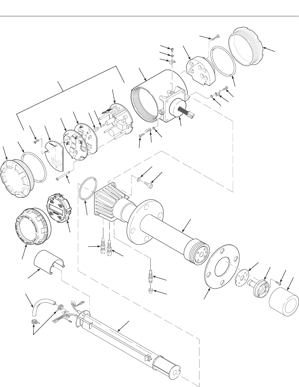
Instruction Manual
IB-106-340C Rev. 4.1
July 2004
9-8 Maintenance and Service Rosemount Analytical Inc. A Division of Emerson Process Management
Hazardous Area Oxymitter 4000
37270004
DIAGNOSTIC
ALARMS
TEST
POINTS
HEATER T/C
HEATER
02 CELL
CALIBRATION
CALIBRATION RECOMMENDED
02 CELL mV +
02 CELL mv -
HEATER T/C +
HEATER T/C -
INC INC
DEC DEC
HIGH
GAS
LOW
GAS
CAL
TEST GAS +
PROCESS -
%02
35
23
34
17A
10
18
18
20
20
19
19
9
34
678
11
12
13
14
15
16
17
2
Note: Not all parts shown.
30
29
29
29
32
25
24
26 27
28
33
22
21
4A
1A
Note: The Electronic Assembly, item 2,
consists of items 3 through 10.
1
17A
1. Blind Cover
1A. Window Cover
2. Electronic Assembly
3. Screw
4. Membrane Keypad
4A. LOI Module
5. Microprocessor Board
6. Analog Board
7. Fuse Cap
8. Fuse
9. Power Supply Board
10. Captive Screw
11. Housing
12. Screw
13. Lock Washer
14. Cable Clamp
15. Terminal Block
16. Captive Screw
17. Blind Cover
17A. O-Ring
18. Screw
19. Cover Lock
20. Captive Washer
21. Washer
22. Screw
23. Probe Tube Assembly
24. Gasket
25. Corrugated Seal
26. Cell and Flange
Assembly
27. Retainer Screw
28. Flame Arrester with
Snubber Diffuser
29. Flame
Arrestor Fitting
30. Cap
31. O-Ring
32. Heater Strut Assembly
33. Tube Clamp
34. Silicon Tube
35. Strut Pressure Clamp
5
31
78
Integral
Electrical
Barrier/
Feedthrough
Figure 9-3. Hazardous Area Oxymitter 4000 with Integral Electronics – Exploded View
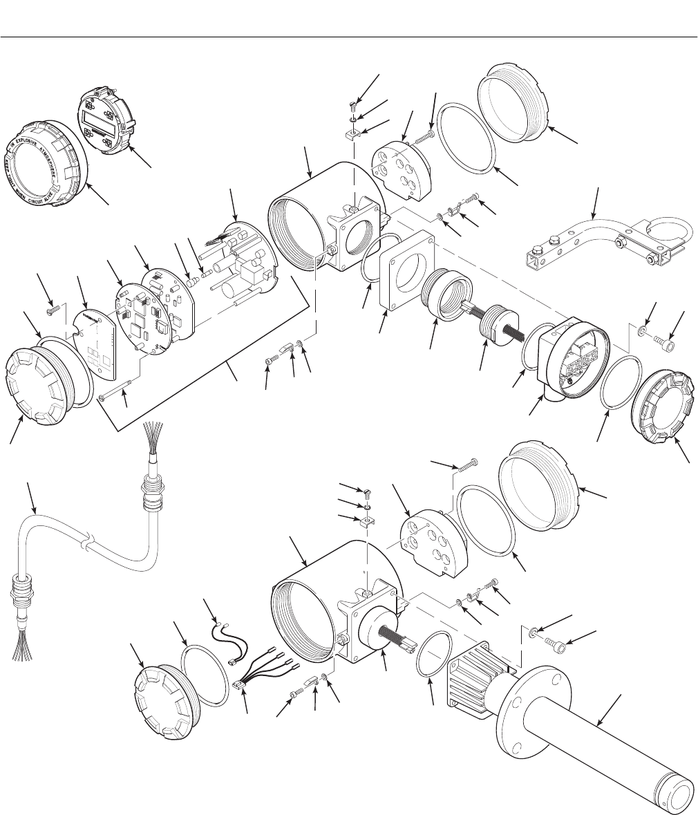
Instruction Manual
IB-106-340C Rev. 4.1
July 2004
Rosemount Analytical Inc. A Division of Emerson Process Management Maintenance and Service 9-9
Hazardous Area Oxymitter 4000
37270005
17A
11
15
17
2
Note: The Electronic Assembly, item 2,
consists of items 3 through 10.
1
23
1A
4A
REMOTE
ELECTRONICS
12
13
14
16
18
20
19
18
20
19
17A
29
18
20
Integral
Electrical
Barrier/
Feedthrough
20
19
19
34
12
13
14
32
16
17
17A
PROBE
HEAD
26
PROBE
Refer to Figure 9-3 for
component parts of probe.
1
17A
18
30
31
INTERCONNECTING
CABLE
15. Terminal Block
16. Captive Screw
17. Blind Cover
17A. O-Ring
18. Screw
19. Cover Lock
20. Captive Washer
21. Lock Washer
22. Screw
23. Mounting Kit
24.
25. Adapter Plug
26. O-Ring
27. Harness Assembly
Junction Box
28. Spacer Block
29. Connecting Cable, Signal
30. Connecting Cable, Heater
31. Interconnecting Cable
32. Terminal Block, Remote Probe Head
33. Probe
34. Housing
22
21
17
24
26
25
27
17A
22
21
28
26
DIAGNOSTIC
ALARMS
TEST
POINTS
HEATERT/C
HEATER
02CELL
CALIBRATION
CALIBRATIONRECOMMENDED
02CELLmV+
02CELLmv-
HEATERT/C+
HEATERT/C -
INCINC
DECDEC
HIGH
GAS
LOW
GAS
CAL
TESTGAS+
PROCESS-
%02
9
34
5
78
6
10
33
1. Blind Cover
1A. Window Cover
2.
3. Screw
4.
4A.
5.
6. Analog Board
7. Fuse Cap
8. Fuse
9. Power Supply Board
Electronic Assembly
Membrane Keypad
LOI Module
Microprocessor Board
10. Captive Screw
11. Housing
12. Screw
13. Lock Washer
14. Cable Clamp
Figure 9-4. Hazardous Area Oxymitter 4000 with Remote Electronics – Exploded View
9
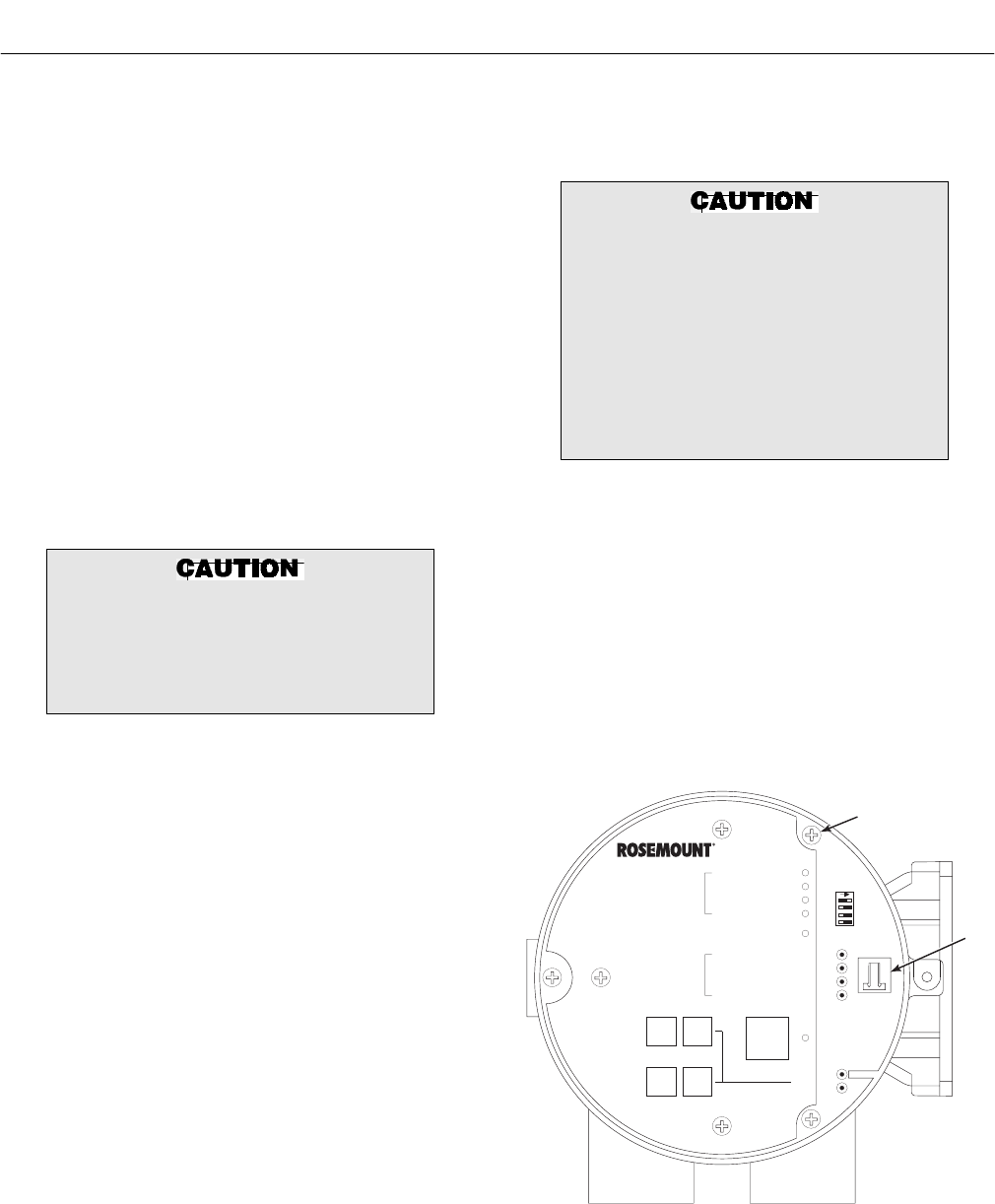
Instruction Manual
IB-106-340C Rev. 4.1
July 2004
9-10 Maintenance and Service Rosemount Analytical Inc. A Division of Emerson Process Management
Hazardous Area Oxymitter 4000
(f) Restore power to the system; refer
to paragraph 5-1 or 6-1. When the
probe is at operating temperature,
calibrate the probe per paragraph
9-2.
NOTE
Recalibration is required whenever
electronic cards or sensing cell is
replaced.
b. Replacement of Entire Electronics
(with Housing) – Hazardous Area
Oxymitter 4000 with Integral Electronics.
1. Follow the instructions in paragraph
9-4a to remove the Hazardous Area
Oxymitter 4000 probe from the stack
or duct.
Do not force the probe housing when
installing or removing from the inte-
gral electrical barrier/feedthrough
(Figure 9-3). Damage to the aluminum
probe housing can occur.
2. Remove four screws (22, Figure 9-3)
and washers (21) from the probe tube
assembly (23). Remove the probe tube
assembly from the housing (11).
3. Disconnect the heater and signal wire
connectors from the mating connectors
on the heater strut assembly (32).
NOTE
The integral electrical barrier/feed-
through is thread-locked into the elec-
trical housing and cannot be
removed.
4. Make sure the O-ring (31) is in good
condition. Replace O-ring if damaged.
5. Make sure that the conduit port of the
electronic housing is on the same side
as the CAL and REF gas ports. Install
four washers (21) and screws (22).
Tighten screws.
6. Follow the instructions in paragraph
2-1b to install the Hazardous Area
Oxymitter 4000 into the stack or duct.
Opening the electronic housing will
cause the loss of ALL hazardous per-
mits. Opening the electronics housing
in hazardous areas may cause an
explosion resulting in loss of property,
severe personal injury, or death. It
may be required to get a hot work
permit from your company safety offi-
cer before opening the electronic
housing.
c. Electronic Assembly Replacement
Remove and replace the electronic assem-
bly according to the following procedure.
1. Remove screw (18, Figure 9-3 or
Figure 9-4), cover lock (19), and cap-
tive washer (20) securing cover (1).
Remove the cover.
2. See Figure 9-5. Depress and remove
the J1 (cell and T/C) connector from
the J1 socket.
DIAGNOSTIC
ALARMS
TEST
POINTS
HEATER T/C
HEATER
O2 CELL
CALIBRATION
CALIBRATION RECOMMENDED
O2 CELL mV +
O2 CELL mv -
HEATER T/C +
HEATER T/C -
INC INC
DEC DEC
HIGH
GAS
LOW
GAS
CAL
TEST GAS +
PROCESS -
% O2
SW2
TP1 J1
TP2
TP3
RED
YEL
GRN
ORG
TP4
TP5
TP6
ON
J1
MOUNTING
SCREW
37270018
Figure 9-5. Electronic Assembly
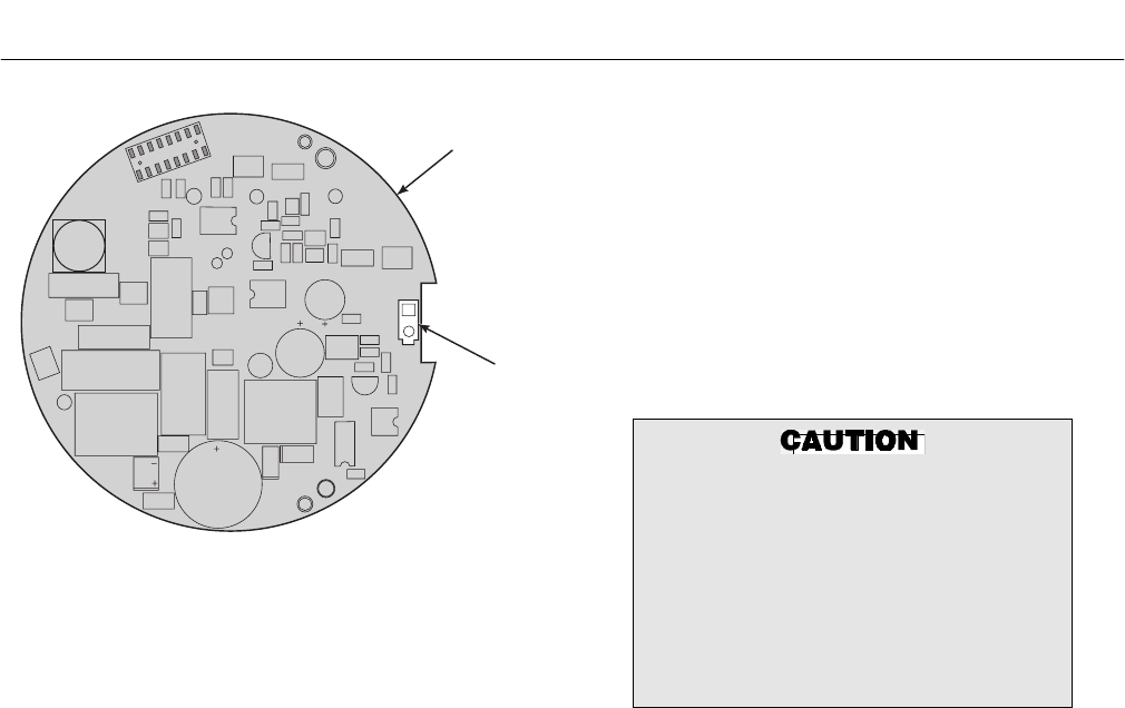
Instruction Manual
IB-106-340C Rev. 4.1
July 2004
Rosemount Analytical Inc. A Division of Emerson Process Management Maintenance and Service 9-11
Hazardous Area Oxymitter 4000
J8
POWER
SUPPLY
BOARD
37270022
Figure 9-6. J8 Connector
3. Loosen the three captive screws
(9, Figure 9-3 or Figure 9-4). Slide
electronic assembly (2) partially out of
housing (11).
4. See Figure 9-6. Squeeze the sides of
the J8 connector, and carefully remove
the J8 connector (heater leads) from
the power supply board.
5. Remove the electronic assembly (2,
Figure 9-3 or Figure 9-4) from the
housing(11).
6. Slide the new electronic assembly (2)
partially into the housing (11).
7. Reconnect the J8 connector to the
power supply board. Make sure the
connector is secure.
8. Holding the J1 connector leads, slide
the electronic assembly the rest of
the way into the housing. Seat the
electronic assembly on the mating
connector pins.
9. Gently try to rotate the electronic
assembly to check for full seating.
If the electronic assembly rotates,
remove the assembly and repeat
step 8.
10. Reconnect the J1 connector to the
microprocessor board (Figure 9-5).
Ensure the connector is secure.
11. Tighten the three captive screws (9,
Figure 9-3 or Figure 9-4) in the top of
the microprocessor board (5).
12. Install and tighten cover (1); make sure
it is tight. Secure the cover using cap-
tive washer (20), cover lock (19), and
screw (18).
Opening the electronic housing will
cause the loss of ALL hazardous per-
mits. Opening the electronics housing
in a hazardous area may cause an
explosion resulting in loss of property,
severe personal injury, or death. It may
be required to get a hot work permit
from your company safety officer be-
fore opening the electronic housing.
d. Terminal Block Replacement
See Figure 9-3 or Figure 9-4.
1. Remove the left side cover (17) from
the housing (11).
2. Loosen the three captive screws (16) in
the terminal block (15). Carefully lift the
terminal block out of the housing.
3. Carefully align the new terminal block
on the pins so that it sits flat in the
housing. The round end of the terminal
block should be on the opposite side of
the housing conduit ports and should
not be able to rotate.
4. Tighten the three mounting screws and
ensure the terminal block is secure in
the housing.
9
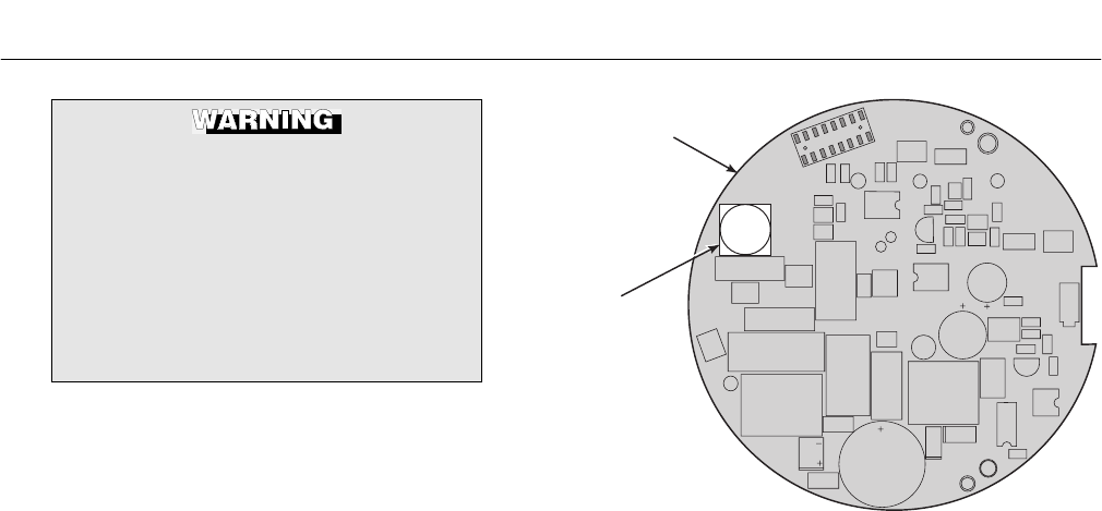
Instruction Manual
IB-106-340C Rev. 4.1
July 2004
9-12 Maintenance and Service Rosemount Analytical Inc. A Division of Emerson Process Management
Hazardous Area Oxymitter 4000
Opening the electronic housing will
cause the loss of ALL hazardous per-
mits. Opening the electronics housing
in a hazardous area may cause an
explosion resulting in loss of property,
severe personal injury, or death. It may
be required to get a hot work permit
from your company safety officer be-
fore opening the electronic housing.
e. Fuse Replacement
See Figure 9-7.
1. Remove screw (18, Figure 9-3 or
Figure 9-4), cover lock (19), and cap-
tive washer (20) securing cover (1).
Remove the cover.
2. See Figure 9-5. Depress and remove
the J1 (cell and T/C) connector from
the J1 socket.
3. Loosen the three captive screws
(10, Figure 9-3 or Figure 9-4). Slide
electronic assembly (2) partially out of
housing (11).
4. See Figure 9-6. Squeeze the sides of
the J8 connector, and carefully remove
the J8 connector (heater leads) from
the power supply board.
5. Remove the electronic assembly (2,
Figure 9-3 or Figure 9-4) from the
housing (11).
6. Turn the electronic assembly over so
that you are looking at the bottom of
the power supply board (Figure 9-7).
7. Gently depress the two white posts one
at a time. Carefully separate the power
supply board from the analog board.
8. Remove the fuse and replace it with a
new one.
FUSE
POWER
SUPPLY
BOARD
37270021
Figure 9-7. Fuse Location
9. Align the white posts with the post
holes on the power supply board and
the pin connector on the power supply
board with the connector port on the
back of the analog board. Gently push
the boards together until the white
posts snap in place. Ensure the as-
sembly is secure by gently trying to
separate the boards.
10. Reconnect the J8 connector to the
power supply board. Make sure the
connector is secure.
11. Holding the J1 connector leads, slide
the electronic assembly the rest of
the way into the housing. Seat the
electronic assembly on the mating
connector pins.
12. Gently try to rotate the electronic
assembly to check for full seating.
If the electronic assembly rotates,
remove the assembly and repeat
step 11.
13. Reconnect the J1 connector to the
microprocessor board (Figure 9-5).
Ensure the connector is secure.
14. Tighten the three captive screws (10,
Figure 9-3 or Figure 9-4) in the top of
the microprocessor board (5).
Instruction Manual
IB-106-340C Rev. 4.1
July 2004
Rosemount Analytical Inc. A Division of Emerson Process Management Maintenance and Service 9-13
Hazardous Area Oxymitter 4000
15. Replace right housing cover (1, Figure
9-3); make sure it is tight. Secure the
cover using captive washer (20), cover
lock (19), and screw (18).
16. Install and tighten cover (1); make sure
it is tight. Secure the cover using cap-
tive washer (20), cover lock (19), and
screw (18).
When working on this equipment on
the laboratory bench, be aware that
the Hazardous Area Oxymitter 4000,
probe tube, and flame arrestor hub
can be hot [up to 300°C (572°F)] in the
region of the probe heater.
f. Entire Probe Replacement
(Excluding Electronics)
Do not attempt to replace the probe until all
other possibilities for poor performance
have been considered. If probe replacement
is needed, see Table 11-1 for part numbers.
1. Follow the instructions in paragraph
9-4a to remove the Hazardous Area
Oxymitter 4000 from the stack or duct.
2. Separate the probe and the electronics
housing per paragraph 9-4b, step 2.
3. Reinstall electronics on the new probe
per paragraph 9-4b, steps 4 and 5.
4. Follow the instructions in paragraph
2-1b to install the Hazardous Area
Oxymitter 4000 into the stack or duct.
When working on this equipment on
the laboratory bench, be aware that
the Hazardous Area Oxymitter 4000,
probe tube, and flame arrestor hub
can be hot [up to 300°C (572°F)] in the
region of the probe heater.
g. Heater Strut Replacement
This paragraph covers heater strut replace-
ment. Do not attempt to replace the heater
strut until all other possibilities for poor per-
formance have been considered. If heater
strut replacement is needed, order a re-
placement heater strut. See Table 11-1.
Use heat resistant gloves and clothing
when removing probe. Do not attempt
to work on the probe until it has
cooled to room temperature. The
probe can be as hot as 300°C (572°F).
This can cause severe burns.
1. Follow the instructions in paragraph
9-4a to remove the Hazardous Area
Oxymitter 4000 from the stack or duct.
2. Remove oxygen sensing cell per para-
graph 9-4h, steps 1 through 5.
Do not force the probe housing when
installing or removing from the inte-
gral electrical barrier/feedthrough
(Figure 9-3). Damage to the aluminum
probe housing can occur.
3. Remove four screws (22, Figure 9-3)
and washers (21) from the probe tube
assembly (23). Remove the probe tube
assembly from the housing (11).
4. Once the probe and housing are sepa-
rated, spring tension releases, and the
heater strut assembly (32) moves up.
Remove strut pressure clamp (35).
5. Disconnect the heater and signal wire
connectors from the mating connectors
on the heater strut assembly (32).
9
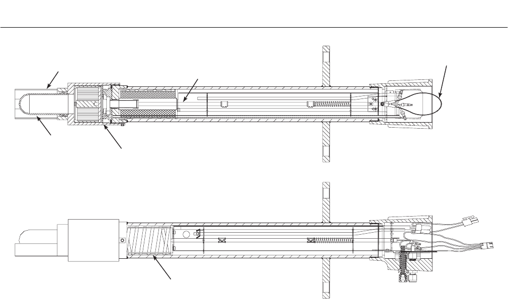
Instruction Manual
IB-106-340C Rev. 4.1
July 2004
9-14 Maintenance and Service Rosemount Analytical Inc. A Division of Emerson Process Management
Hazardous Area Oxymitter 4000
27540007
WIRE
LOOP
CERAMIC SUPPORT ROD
CELL FLANGE
HEATER
CERAMIC
DIFFUSER
ASSEMBLY
V-DEFLECTOR
Figure 9-8. Heater Strut Assembly
6. Remove tube clamps (33). Carefully
pull the CAL and REF gas silicon tubes
(34) from the CAL and REF gas ports.
7. Remove gas port fittings (29) from the
CAL, REF, and VENT ports.
8. See Figure 9-8. Grasp the wire loop
and carefully slide the heater strut
assembly (32, Figure 9-3) out of the
probe tube.
9. When replacing the strut, orient the
probe so that the small calibration gas
tube lays at the 6 o’clock position of the
probe tube. Align the slot on the heater
plate with the calibration gas line in the
probe tube. Slide the strut into the
probe tube. It will turn to align the hole
on the back plate of the strut with the
calibration gas line. When the hole and
the calibration gas line are aligned cor-
rectly, the strut will slide in the rest of
the way.
10. As the strut installation nears comple-
tion, install the guide rod into the cali-
bration gas tube to assist in guiding the
calibration gas tube through the hole in
the end of the strut.
11. Push down on the back plate of the
strut to make sure you have spring
tension and then install the strut pres-
sure clamp (34) on the back plate.
12. Install gas port fittings (29) in the CAL,
REF, and VENT ports.
13. Replace the CAL and REF gas silicon
tubes (34) and tube clamps (33).
14. Install the entire electronics per para-
graph 9-4b, steps 4 and 5.
15. Follow the instructions in paragraph
2-1b to install the Hazardous Area
Oxymitter 4000 into the stack or duct.
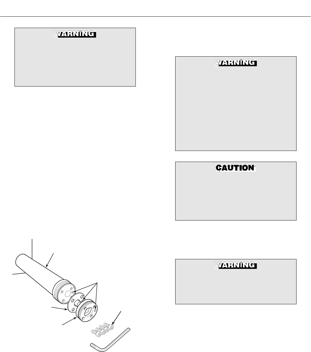
Instruction Manual
IB-106-340C Rev. 4.1
July 2004
Rosemount Analytical Inc. A Division of Emerson Process Management Maintenance and Service 9-15
Hazardous Area Oxymitter 4000
When working on this equipment on
the laboratory bench, be aware that
the Hazardous Area Oxymitter 4000,
probe tube, and flame arrestor hub
can be hot [up to 300°C (572°F)] in the
region of the probe heater.
h. Cell Replacement
This paragraph covers O2 cell replacement.
Do not attempt to replace the cell until all
other possibilities for poor performance
have been considered. If cell replacement
is needed, order the cell replacement kit.
See Table 11-1.
The cell replacement kit (Figure 9-9) con-
tains a cell and flange assembly, corrugated
seal, setscrews, socket head cap screws,
and anti-seize compound. The items are
carefully packaged to preserve precise
surface finishes. Do not remove items from
the packaging until they are ready to be
used. Spanner and hex wrenches needed
for this procedure are part of an available
special tools kit. See Table 11-1.
SOCKET HEAD
CAP SCREWS
CALIBRATION GAS
PASSAGE
26310016
PROBE TUBE
(NOT INCLUDED
IN KIT)
CORRUGATED
SEAL
CELL AND
FLANGE
ASSEMBLY
Figure 9-9. Cell Replacement Kit
Spanner and hex wrenches needed for this
procedure are part of an available special
tools kit. See Table 11-1.
Use heat-resistant gloves and clothing
when removing the probe. Do not at-
tempt to work on these components
until they have cooled to room tem-
perature. Probe components can be as
hot as 300°C (572°F). This can cause
severe burns.
Disconnect and lock out power before
working on any electrical components.
There is voltage of up to 115 VAC.
Do not remove the cell unless certain
it needs to be replaced. Removal may
damage the cell and platinum pad. Go
through the complete troubleshooting
procedure to make sure the cell needs
to be replaced before removing it.
1. Follow the instructions in paragraph
9-4a to remove the Hazardous Area
Oxymitter 4000 from the stack or duct.
The flame arrestor and flame arrestor
hub are among the critical compo-
nents of this type of protection. See
Safety Data Sheet 1A99078.
2. If the probe uses a snubber diffuser,
use a spanner wrench to remove the
flame arrestor/snubber diffuser assem-
bly.
NOTE
To determine if the diffuser needs to
be replaced, refer to paragraph 9-2.
9
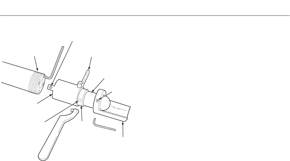
Instruction Manual
IB-106-340C Rev. 4.1
July 2004
9-16 Maintenance and Service Rosemount Analytical Inc. A Division of Emerson Process Management
Hazardous Area Oxymitter 4000
27540008
PORT
CEMENT
THREADED
PROBE FLANGE
SPANNER
WRENCH
M5-0.8 x 5 mm
LOCKING SET SCREW
(USE 2.5 mm HEX KEY)
CERAMIC
DIFFUSION
ELEMENT
M6-1 x 6 mm
SETSCREW
(USE 3 mm
HEX KEY)
CEMENT
FILLET
VEE
DEFLECTOR
FLAME
ARRESTER
HUB
Figure 9-10. Ceramic Diffuser Element
Replacement
3. Remove the locking set screw from the
flame arrestor. Use spanner wrenches
from the probe disassembly kit (Table
11-1) to turn the flame arrestor hub
free from the probe flange. If equipped
with the flame arrestor with ceramic
diffuser, remove and discard the
setscrews and remove the vee deflec-
tor (Figure 9-10). Inspect the ceramic
diffuser. If damaged, replace using
paragraph 9-4i.
4. Loosen the four socket head cap
screws from the cell and flange as-
sembly. Remove the assembly and the
corrugated seal. The cell flange has a
notch that may be used to gently pry
the flange away from the probe. Note
that the contact pad inside of the probe
will sometimes fuse to the oxygen
sensing cell. If the cell is fused to the
contact pad, push the cell assembly
back into the probe (against spring
pressure) and quickly twist the cell as-
sembly. The cell and contact pad
should separate. If the contact pad
stays fused to the cell, a new con-
tact/thermocouple assembly must be
installed. Disconnect the orange cell
wire at the probe electronics end of the
strut by cutting the wire. Withdraw the
cell with the wire still attached.
5. Remove entire electronics per para-
graph 9-4b, steps 2 and 3.
6. If the contact and thermocouple
assembly is damaged, replace the
assembly or the contact pad. Refer to
paragraph 9-4j to replace the contact
and thermocouple assembly. Instruc-
tions for replacing the contact pad are
in the cell replacement kit.
7. Remove and discard the corrugated
seal. Clean the mating faces of the
probe tube and cell. Remove burrs and
raised surfaces with a block of wood
and crocus cloth. Clean the threads on
the probe flange and flame arrestor
hub.
8. Apply a light coating of anti-seize
compound to both sides of the new
corrugated seal.
9. Assemble the cell and flange assembly
and corrugated seal to the probe tube.
Make sure the calibration tube lines up
with the calibration gas passage in
each component. Apply a small
amount of anti-seize compound to the
screw threads and use the screws to
secure the assembly. Torque to 4 N·m
(35 in-lbs).
10. Apply anti-seize compound to the
probe threads, flame arrestor hub, and
setscrews. Reinstall the flame arrestor
on the probe. Using pin spanner
wrenches, torque to 14 N·m (10 ft-lbs).
Secure the flame arrestor with the
locking setscrew. Torque to 2.8 N·m
(25 in-lbs). If applicable, reinstall the
vee deflector, orienting apex toward
gas flow. Secure with the setscrew and
anti-seize compound. Torque to 2.8
N·m (25 in-lbs).
11. On systems equipped with an abrasive
shield, install the dust seal gaskets,
with joints 180° apart.

Instruction Manual
IB-106-340C Rev. 4.1
July 2004
Rosemount Analytical Inc. A Division of Emerson Process Management Maintenance and Service 9-17
Hazardous Area Oxymitter 4000
12. If previously removed, install the entire
electronics per paragraph 9-4b, steps
4 and 5.
13. Follow the instructions in paragraph
2-1b to install the Hazardous Area
Oxymitter 4000 into the stack or duct. If
there is an abrasive shield in the stack,
make sure the dust seal gaskets are in
place as they enter the 15° reducing
cone.
i. Ceramic Diffusion Element Replacement
NOTE
This procedure applies to the ceramic
diffuser element only.
1. General
The diffusion element protects the O2
cell from particles in process gases.
The element does not normally need to
be replaced, because the vee deflector
protects it from particulate erosion. In
severe environments, the filter may be
broken or subject to excessive erosion.
Examine the ceramic diffusion element
whenever removing the probe for any
purpose. Replace if damaged.
Damage to the diffusion element may
become apparent during calibration.
Compare probe response with previous
response. A broken diffusion element
will cause a slower response to cali-
bration gas.
Hex wrenches needed to remove
setscrews and socket head screws in
the following procedure are available
as part of a Probe Disassembly Kit,
Table 11-1.
2. Replacement Procedure
(a) Follow the instructions given in
paragraph 9-4a to remove the
Hazardous Area Oxymitter 4000
from the stack or duct.
(b) Loosen setscrews, Figure 9-10,
using hex wrench from Probe
Disassembly Kit, Table 11-1 and
remove vee deflector. Inspect
setscrews. If damaged, replace
with stainless setscrews coated
with anti-seize compound.
(c) On systems equipped with abra-
sive shield, remove dual dust seal
gaskets.
(d) Use spanner wrenches from the
Probe Disassembly Kit, Table
11-1, to turn hub free from retainer.
(e) Put the hub in vise. Break out old
ceramic diffusion element with
chisel along cement line and 9.5
mm (3/8 in.) pin punch through
cement port.
(f) Break out remaining ceramic diffu-
sion element by tapping lightly
around hub with hammer. Clean
grooves with pointed tool if neces-
sary.
(g) Replace ceramic diffusion element
using the ceramic diffusion ele-
ment replacement kit in Table
11-1. This consists of a diffusion
element, cement, setscrews, anti-
seize compound and instructions.
(h) Test fit replacement ceramic diffu-
sion element to be sure seat is
clean.
Do not get cement on ceramic diffu-
sion element except where it touches
the hub. Any cement on ceramic diffu-
sion element blocks airflow through
element. Wiping wet cement off of the
ceramic only forces cement into
pores. Also do not get any cement
onto the flame arrestor element.
(i) Thoroughly mix cement and insert
tip of squeeze bottle into cement
port. Tilt bottle and squeeze while
simultaneously turning ceramic
9

Instruction Manual
IB-106-340C Rev. 4.1
July 2004
9-18 Maintenance and Service Rosemount Analytical Inc. A Division of Emerson Process Management
Hazardous Area Oxymitter 4000
diffusion element into seat. Do not
get any cement on upper part of
ceramic diffusion element. Ensure
complete penetration of cement
around 3 grooves in hub. Cement
should extrude from opposite hole.
Wipe excess material back into
holes and wipe top fillet of cement
to form a uniform fillet. (A Q-Tip is
useful for this.) Clean any excess
cement from hub with water.
(j) Allow filter to dry at room tem-
perature overnight or 1 to 2 hours
at 93°C (200°F).
(k) Wipe a heavy layer of anti-seize
compound onto the threads and
mating surfaces of the flame arre-
stor, diffusion hub, and probe tube.
(l) Assemble flame arrestor and diffu-
sion hub with two pin spanner
wrenches. Torque to 14 N·m (10 ft-
lbs). Secure with hub retaining
setscrew.
(m) On systems equipped with abra-
sive shield, install dust seal gas-
kets with joints 180° apart.
(n) Reinstall vee deflector, orienting
apex toward gas flow. Apply anti-
seize compound to setscrews and
tighten with hex wrench.
(o) Reinstall probe on stack flange.
j. Contact and Thermocouple Assembly
Replacement
See Figure 9-11.
1. Remove the cell per paragraph 9-4h,
steps 1 through 5.
2. Remove the heater strut assembly per
paragraph 9-4g, steps 3 through 8.
3. Use a pencil to mark locations of the
spring clips on the ceramic rod of the
contact and thermocouple assembly.
4. Squeeze the tabs on the spring clips
and pull the contact and thermocouple
assembly out of the heater strut. Retain
the spring clips and spring; replace if
damaged.
5. While very carefully handling the new
contact and thermocouple assembly,
lay the old assembly next to the new
one. Transfer the pencil marks to the
new rod. Throw away the old contact
and thermocouple assembly.
6. Carefully guide the new contact and
thermocouple assembly through the
spring, spring clips (held open by
squeezing the tabs), tube supports,
and heater support of the heater strut
assembly until the spring clip reaches
the pencil mark.
7. Install the cell per the instructions in
paragraph 9-4h, steps 7 through 12.
8. Slide the heater strut assembly into the
probe per the instructions in paragraph
9-4g, steps 9 through 14.
9. On systems equipped with an abrasive
shield, install the dust seal gaskets,
with joints 180° apart.
10. Follow instructions in paragraph 2-1b
to install the Hazardous Area Oxymitter
4000 into the stack or duct. If there is
an abrasive shield in the stack, make
sure the dust seal gaskets are in place
as they enter the 15° reducing cone.
26310022
STRUT
TUBE
SUPPORTS
CONTACT AND
THERMOCOUPLE
ASSEMBLY
SPRING
CLIP
SPRING
Figure 9-11. Contact and Thermocouple Assembly
Replacement

Instruction Manual
IB-106-340C Rev. 4.1
July 2004
Rosemount Analytical Inc. A Division of Emerson Process Management Return of Material 10-1
Hazardous Area Oxymitter 4000
SECTION 10
RETURN OF MATERIAL
10-1 If factory repair of defective equipment is
required, proceed as follows:
a. Secure a return authorization number from
a Rosemount Analytical Sales Office or rep-
resentative before returning the equipment.
Equipment must be returned with complete
identification in accordance with Rosemount
instructions or it will not be accepted.
In no event will Rosemount be responsible
for equipment returned without proper
authorization and identification.
b. Carefully pack defective unit in a sturdy box
with sufficient shock absorbing material to
ensure that no additional damage will occur
during shipping.
c. In a cover letter, describe completely:
1. The symptoms from which it was
determined that the equipment is
faulty.
2. The environment in which the equip-
ment has been operating (housing,
weather, vibration, dust, etc.).
3. Site from which equipment was
removed.
4. Whether warranty or nonwarranty
service is requested.
5. Complete shipping instructions for
return of equipment.
6. Reference the return authorization
number.
d. Enclose a cover letter and purchase order
and ship the defective equipment according
to instructions provided in Rosemount
Return Authorization, prepaid, to:
Rosemount Analytical Inc.
RMR Department
1201 N. Main Street
Orrville, Ohio 44667
If warranty service is requested, the defec-
tive unit will be carefully inspected and
tested at the factory. If failure was due to
conditions listed in the standard Rosemount
warranty, the defective unit will be repaired
or replaced at Rosemount's option, and an
operating unit will be returned to the cus-
tomer in accordance with shipping instruc-
tions furnished in the cover letter.
For equipment no longer under warranty,
the equipment will be repaired at the factory
and returned as directed by the purchase
order and shipping instructions.
10

Instruction Manual
IB-106-340C Rev. 4.1
July 2004
10-2 Return of Material Rosemount Analytical Inc. A Division of Emerson Process Management
Hazardous Area Oxymitter 4000

Instruction Manual
IB-106-340C Rev. 4.1
July 2004
Rosemount Analytical Inc. A Division of Emerson Process Management Replacement Parts 11-1
Hazardous Area Oxymitter 4000
SECTION 11
REPLACEMENT PARTS
Table 11-1. Replacement Parts for Probe
Figure and
Index No. Part Number Description
(Dust Seal) (No Dust Seal)
9-4, 33 3D39746G01 3D39745G01 18" ANSI Flame Arrestor with Ceramic Diffuser Probe
9-4, 33 3D39746G02 3D39745G02 3' ANSI Flame Arrestor with Ceramic Diffuser Probe
9-4, 33 3D39746G03 3D39745G03 6' ANSI Flame Arrestor with Ceramic Diffuser Probe
9-4, 33 3D39746G04 3D39745G04 18" JIS Flame Arrestor with Ceramic Diffuser Probe
9-4, 33 3D39746G05 3D39745G05 3' JIS Flame Arrestor with Ceramic Diffuser Probe
9-4, 33 3D39746G06 3D39745G06 6' JIS Flame Arrestor with Ceramic Diffuser Probe
9-4, 33 3D39746G07 3D39745G07 18" DIN Flame Arrestor with Ceramic Diffuser Probe
9-4, 33 3D39746G08 3D39745G08 3' DIN Flame Arrestor with Ceramic Diffuser Probe
9-4, 33 3D39746G09 3D39745G09 6' DIN Flame Arrestor with Ceramic Diffuser Probe
9-4, 33 3D39746G10 3D39745G10 18" ANSI Flame Arrestor with Snubber Diffuser Probe
9-4, 33 3D39746G11 3D39745G11 3' ANSI Flame Arrestor with Snubber Diffuser Probe
9-4, 33 3D39746G12 3D39745G12 6' ANSI Flame Arrestor with Snubber Diffuser Probe
9-4, 33 3D39746G13 3D39745G13 18" JIS Flame Arrestor with Snubber Diffuser Probe
9-4, 33 3D39746G14 3D39745G14 3' JIS Flame Arrestor with Snubber Diffuser Probe
9-4, 33 3D39746G15 3D39745G15 6' JIS Flame Arrestor with Snubber Diffuser Probe
9-4, 33 3D39746G16 3D39745G16 18" DIN Flame Arrestor with Snubber Diffuser Probe
9-4, 33 3D39746G17 3D39745G17 3' DIN Flame Arrestor with Snubber Diffuser Probe
9-4, 33 3D39746G18 3D39745G18 6' DIN Flame Arrestor with Snubber Diffuser Probe
9-3, 32 3D39744G01 18" Heater Strut Assy.
9-3, 32 3D39744G02 3' Heater Strut Assy.
9-3, 32 3D39744G03 6' Heater Strut Assy.
11-1 4847B61G20 DIN 3' Cell Replacement Kit*
11-1 4847B61G21 DIN 6' Cell Replacement Kit*
11-1 4847B61G25 DIN 18" Cell Replacement Kit*
11-1 4847B61G26 ANSI 18" Cell Replacement Kit*
11-1 4847B61G27 ANSI 3' Cell Replacement Kit*
11-1 4847B61G28 ANSI 6' Cell Replacement Kit*
11-1 4847B61G29 JIS 18" Cell Replacement Kit*
11-1 4847B61G30 JIS 3' Cell Replacement Kit*
11-1 4847B61G31 JIS 6' Cell Replacement Kit*
4849B94G01 ANSI High Sulfur/HCl Resistant Cell Only
11-1 4849B94G02 ANSI 18" Cell Replacement Kit, High
Sulfur/HCl Resistant*
11-1 4849B94G03 ANSI 3' Cell Replacement Kit, High Sulfur/HCl
Resistant*
11-1 4849B94G04 ANSI 6' Cell Replacement Kit, High Sulfur/HCl
Resistant*
*Includes pad and wire.
11
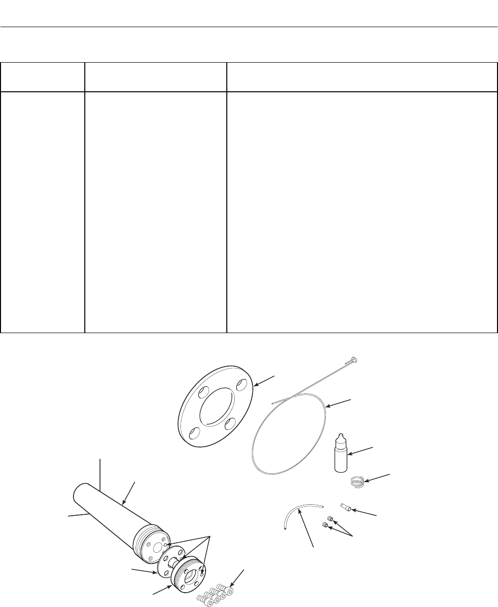
Instruction Manual
IB-106-340C Rev. 4.1
July 2004
11-2 Replacement Parts Rosemount Analytical Inc. A Division of Emerson Process Management
Hazardous Area Oxymitter 4000
Table 11-1. Replacement Parts for Probe (Continued)
Figure and
Index No. Part Number Description
4849B94G07 JIS High Sulfur/HCl Resistant Cell Only
11-1 4849B94G08 JIS 18" Cell Replacement Kit, High Sulfur/HCl Resistant*
11-1 4849B94G09 JIS 3' Cell Replacement Kit, High Sulfur/HCl Resistant*
11-1 4849B94G10 JIS 6' Cell Replacement Kit, High Sulfur/HCl Resistant*
4849B94G13 DIN High Sulfur/HCl Resistant Cell Only
11-1 4849B94G15 DIN 3' Cell Replacement Kit, High Sulfur/HCl Resistant*
11-1 4849B94G16 DIN 6' Cell Replacement Kit, High Sulfur/HCl Resistant*
1-11 3D39003G16 ANSI 18" Abrasive Shield Assy.
1-11 3D39003G17 ANSI 3' Abrasive Shield Assy.
1-11 3D39003G18 ANSI 6' Abrasive Shield Assy.
1-11 3D39003G19 DIN 18" Abrasive Shield Assy.
1-11 3D39003G20 DIN 3' Abrasive Shield Assy.
1-11 3D39003G21 DIN 6' Abrasive Shield Assy.
1-11 3D39003G22 JIS 18" Abrasive Shield Assy.
1-11 3D39003G23 JIS 3' Abrasive Shield Assy.
1-11 3D39003G24 JIS 6' Abrasive Shield Assy.
4513C61G03 18" Contact and Thermocouple Replacement Assy.
4513C61G04 3' Contact and Thermocouple Replacement Assy.
4513C61G05 6' Contact and Thermocouple Replacement Assy.
*Includes pad and wire.
PROBE TUBE
(NOT INCLUDED
IN KIT)
M6-1 x 6 mm
SOCKET HEAD
CAP SCREWS
CORRUGATED
SEAL
ANSI
GASKET
WIRE AND
PAD ASSEMBLY
ANTI-SEIZE
COMPOUND
22 GA.
WIRE
SET SCREWS
TEFLON
TUBING
CLOSED END
CONNECTOR
CELL AND
FLANGE
ASSEMBLY
CALIBRATION GAS
PASSAGE
27540010
Figure 11-1. Cell Replacement Kit

Instruction Manual
IB-106-340C Rev. 4.1
July 2004
Rosemount Analytical Inc. A Division of Emerson Process Management Replacement Parts 11-3
Hazardous Area Oxymitter 4000
Table 11-1. Replacement Parts for Probe (Continued)
Figure and
Index No. Part Number Description
4507C26G07 Bypass Gas Pickup Tube (3’)
4507C26G08 Bypass Gas Pickup Tube (6’)
4507C26G09 Bypass Gas Pickup Tube (9’)
2-1 1U05677G01 Flame Arrestor with Ceramic Diffuser
2-2 1U05677G02 Flame Arrestor with Ceramic Diffuser and Dust Seal
2-2 1U05677G03 Flame Arrestor with Ceramic Diffuser and Spare Dust Seal
2-1 1U05677G04 Flame Arrestor with Snubber Diffuser
2-2 1U05677G05 Flame Arrestor with Snubber Diffuser and Dust Seal
2-2 1U05677G06 Flame Arrestor with Snubber Diffuser and Spare Dust Seal
9-10 1L03650H01 Flame Arrestor Diffusion Hub Setscrew (M5-0.8 x 5 mm)
2-8 263C152G01 Reference Gas Air Set
771B635H01 Calibration Gas Flowmeter
11-2 3535B42G03 Probe Disassembly Kit
9-3, 35 5R10130H01 Strut Pressure Clamp
9-10 6292A74G02 Ceramic Diffusion Element Replacement Kit
HEX KEYS
TUBE INSERTION
TUBE
PHILIPS
SCREWDRIVER
SPANNER
WRENCH
ANTI-SEIZE
COMPOUND
26310008
Figure 11-2. Probe Disassembly Kit
11

Instruction Manual
IB-106-340C Rev. 4.1
July 2004
11-4 Replacement Parts Rosemount Analytical Inc. A Division of Emerson Process Management
Hazardous Area Oxymitter 4000
Table 11-2. Replacement Parts for Electronics
Figure and
Index No. Part Number Description
9-3, 1, 17 5R10145G01 Cover, Blind
9-3, 1A 08732-0007-0002 Cover, with Window
9-3, 2 3D39861G01 Electronic Assembly
9-3, 4 4849B72H01 Membrane Keypad English
9-3, 4 4849B72H02 Membrane Keypad German
9-3, 4 4849B72H03 Membrane Keypad French
9-3, 4 4849B72H04 Membrane Keypad Spanish
9-3, 4 4849B72H05 Membrane Keypad Italian
9-3, 4A 6A00115G01 LOI Module (Local Operator Interface)
9-3, 11 4850B86G01 Housing
9-3, 15 08732-0002-0001 Termination Block Standard
9-3, 15 08732-0002-0002 Termination Block Transient Protected
9-3, 17A 120039078 O-Ring
9-3, 31 120039076 O-Ring
9-4, 2 3D39861G01 Electronic Assembly
9-4, 4 4849B72H01 Membrane Keypad English
9-4, 4 4849B72H02 Membrane Keypad German
9-4, 4 4849B72H03 Membrane Keypad French
9-4, 4 4849B72H04 Membrane Keypad Spanish
9-4, 4 4849B72H05 Membrane Keypad Italian
9-4, 4A 6A00115G01 LOI Module (Local Operator Interface)
9-4, 11 5R10146G04 Housing
9-4, 15 08732-0002-0001 Termination Block Standard
9-4, 15 08732-0002-0002 Termination Block Transient Protected
9-4, 17A 120039078 O-Ring
9-4, 24 6A00091G02 Junction Box
9-4, 26 120039076 O-Ring
9-4, 29 4849B92G20 Connecting Cable, Signal
9-4, 30 4849B92G21 Connecting Cable, Heater
9-4, 31 6A00122G01 Cable Assembly, 20 ft. (6 m)
9-4, 31 6A00122G02 Cable Assembly, 40 ft. (12 m)
9-4, 31 6A00122G03 Cable Assembly, 60 ft. (18 m)
9-4, 31 6A00122G04 Cable Assembly, 80 ft. (24 m)
9-4, 31 6A00122G05 Cable Assembly, 100 ft. (30 m)
9-4, 31 6A00122G06 Cable Assembly, 150 ft. (46 m)
9-4, 31 6A00122G07 Cable Assembly, 200 ft. (61 m)
9-4, 32 3D39866G01 Termination Block, Standard, Remote Probe Head
9-4, 32 3D39866G02 Termination Block, Transient Protected, Remote Probe
Head
9-4, 34 4850B86G01 Housing
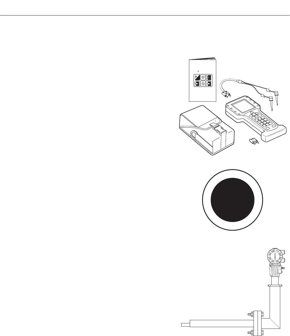
Instruction Manual
IB-106-340C Rev. 4.1
July 2004
Rosemount Analytical Inc. A Division of Emerson Process Management Optional Accessories 12-1
Hazardous Area Oxymitter 4000
SECTION 12
OPTIONAL ACCESSORIES
HART HANDHELD 375 COMMUNICATOR
The HART Handheld 375 Communicator is an interface device
that provides a common communication link to HART-compatible
instruments, such as the Oxymitter 4000. HART Communica-
tions Protocol permits all the information available from the
Oxymitter 4000’s electronics to be transmitted over standard
4-20 mA signal wires. By attaching the HART handheld commu-
nicator at a termination point along the 4-20 mA signal line, a
technician can diagnose problems and configure and calibrate
the Hazardous Area Oxymitter 4000 as if he or she were stand-
ing in front of the instrument.
For more information, call Rosemount Analytical at
1-800-433-6076.
o
HART
Communicator
FISHER-ROSEMOUNT
TM
MAN 4275A00
English
October 1994
37260059
ASSET MANAGEMENT SOLUTIONS (AMS)
Asset Management Solutions (AMS) software works in con-
junction with the HART Communication Protocol and offers the
capability to communicate with all HART plant devices from a
single computer terminal.
For more information, call Rosemount Analytical at
1-800-433-6076.
C
H
A
N
G
I
N
G
T
H
E
W
A
Y
Y
O
U
S
E
E
Y
O
U
R
P
L
A
N
T
F
I
S
H
E
R
-
R
O
S
E
M
O
U
N
T
ASSET
MANAGEMENT
SOLUTIONS
26170010
BY-PASS PACKAGES
The specially designed Rosemount Analytical By-Pass Package
for oxygen analyzers has proven to withstand the high tempera-
tures in process heaters while providing the same advantages
offered by the in situ sensor. Inconel or Kanthal steel tubes pro-
vide effective resistance to corrosion, and the package uses no
moving parts, air pumps, or other components common to other
sampling systems.
For more information, call Rosemount Analytical at
1-800-433-6076.
P
S
U
E
I
T
P
I
C
R
H
W
E
N
T
H
G
C
E
N
I
E
E
R
W
A
V
I
S
O
L
P
-
X
O
M
T
A
G
N
I
N
-
R
I
T
L
A
I
V
E
-
E
E
H
GAS
CAL.
26170024
12
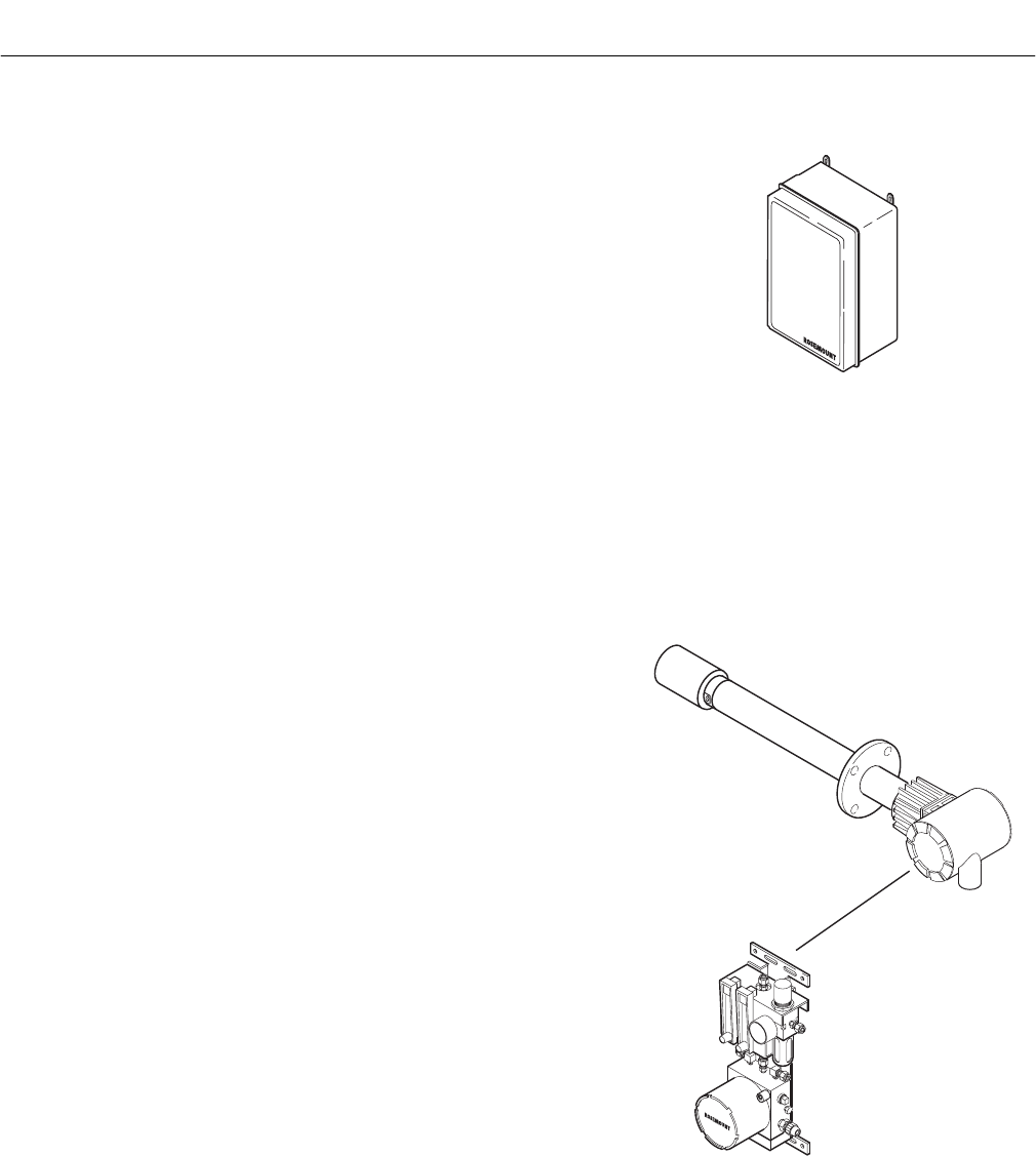
Instruction Manual
IB-106-340C Rev. 4.1
July 2004
12-2 Optional Accessories Rosemount Analytical Inc. A Division of Emerson Process Management
Hazardous Area Oxymitter 4000
IMPS 4000 INTELLIGENT MULTIPROBE TEST
GAS SEQUENCER
The IMPS 4000 Intelligent Multiprobe Test Gas Sequencer
is housed within an IP56 (NEMA 4X) enclosure and has the
intelligence to provide calibration gas sequencing of up to four
Hazardous Area Oxymitter 4000 units to accommodate auto-
matic and semi-automatic calibration routines.
This sequencer works in conjunction with the Hazardous Area
Oxymitter 4000 CALIBRATION RECOMMENDED feature,
eliminating out-of-calibration occurrences and the need to send
a technician to the installation site. In addition, the SPS 4000
provides a remote contact input to initiate a calibration from a
remote location and relay outputs to alert when a calibration is in
progress, a Hazardous Area Oxymitter 4000 is out of calibration,
calibration gases are on, or calibration gas pressure is low.
For more information, call Rosemount Analytical at
1-800-433-6076.
26170006
SPS 4000 SINGLE PROBE
AUTOCALIBRATION SEQUENCER
Rosemount Analytical specifically designed the SPS 4000 Single
Probe Autocalibration Sequencer to provide the capability to
perform automatic or on-demand Oxymitter 4000 calibrations.
The SPS 4000 system must be installed a remote, safe area
if the Hazardous Area Oxymitter 4000 probe is installed in a
hazardous area.
The SPS 4000 works in conjunction with the Oxymitter 4000’s
CALIBRATION RECOMMENDED feature, eliminating out-of-
calibration occurrences and the need to send a technician to the
installation site. In addition, the SPS 4000 provides a remote
contact input to initiate a calibration from a remote location and
relay outputs to indicate when a calibration is in progress or the
Hazardous Area Oxymitter 4000 is out of calibration.
For more information, call Rosemount Analytical at
1-800-433-6076.
REMOTE MOUNTED
SPS 4000
(IN A SAFE AREA)
26310009
HAZARDOUS AREA
OXYMITTER 4000
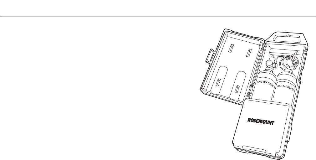
Instruction Manual
IB-106-340C Rev. 4.1
July 2004
Rosemount Analytical Inc. A Division of Emerson Process Management Optional Accessories 12-3
Hazardous Area Oxymitter 4000
O2 CALIBRATION GAS
Rosemount Analytical’s O2 Calibration Gas and Service Kits
have been carefully designed to provide a more convenient and
fully portable means of testing, calibrating, and servicing
Rosemount Analytical’s oxygen analyzers. These lightweight,
disposable gas cylinders eliminate the need to rent gas bottles.
For more information, call Rosemount Analytical at
1-800-433-6076.
26170021
12

Instruction Manual
IB-106-340C Rev. 4.1
July 2004
12-4 Optional Accessories Rosemount Analytical Inc. A Division of Emerson Process Management
Hazardous Area Oxymitter 4000

Instruction Manual
IB-106-340C Rev. 4.1
July 2004
Rosemount Analytical Inc. A Division of Emerson Process Management Optional Accessories 13-1
Hazardous Area Oxymitter 4000
SECTION 13
INDEX
This index is an alphabetized listing of parts, terms, and procedures having to do with the
Hazardous Area Oxymitter. Every item listed in this index refers to a location in the manual
by one or more page numbers.
A
Abrasive Shield, 2-1, 2-4, 2-7, 2-9, 2-11, 11-2
Absolute Temperature, 1-1
Accuracy, 1-12
Alarm Modes, 3-4, 4-4, 7-4
Alarms, 3-4, 4-4, 5-2, 7-4, 8-2
Alarms, Diagnostic, 8-4
Alarms, Unit, 8-4
AMS Software, 1-1, 1-5, 3-2, 4-2, 9-3, 12-1
Analog Output Signal (4-20 mA), 1-1, 1-3, 1-4, 1-5,
1-9, 1-12, 2-9, 2-11, 3-2, 3-3, 4-2, 4-3, 7-1, 7-2, 7-3
Arithmetic Constant, 1-1
Autocalibration, 9-1, 9-2
B
By-Pass Packages, 12-1
C
Calibration, 7-8, 7-9, 9-1
Calibration Gas, 1-9, 2-15, 3-3, 9-1, 9-5, 12-2, 12-3
Calibration Handshake, 2-9, 2-11, 2-14, 3-4, 4-4
CALIBRATION RECOMMENDED, 1-4, 3-4, 4-4, 5-2,
7-4, 9-3, 12-2
Cell, 1-3, 8-17, 8-18, 9-1, 9-15
Cell Constant, 1-1
Cell Replacement Kit, 9-15, 11-1
Check Valve, 1-9
Constant, 8-18
Contact and Thermocouple Assembly, 9-18
D
Diffusion Element, 2-7, 9-1, 9-17
Drip Loop, 2-7, 2-8
E
EEPROM, 8-16
Electrical Installation, 2-8, 2-11
Electrical Noise, 8-2
Electrostatic Discharge, 8-2
Equipment Return, 10-1
Error, 5-1
F
Fuse, 9-12
G
Grounding, 8-2
H
HART, 1-4, 3-2, 4-2, 7-1, 9-2, 9-3, 12-1
HART Communicator, 1-1, 1-2, 1-4, 12-1
HART Menu Tree, 7-5, 7-6, 7-7
Hazardous Area Certifications, 1-13
Heater, 1-5, 1-13, 8-9, 8-11
Heater Strut Assembly, 9-13, 9-14, 11-1
I
IMPS 4000, 1-2, 1-3, 1-6, 1-8, 1-9, 3-4, 3-5, 4-4, 4-5,
9-2, 9-3, 12-2
Instrument Air, 1-9, 2-14
Insulation, 2-7, 2-8, 9-7
Integral Electronics, 1-2, 1-3, 1-5, 3-1, 4-1
Integrated Circuits, 8-2
K
Keypad, Membrane, 4-3, 6-1
L
Languages, 1-5
LEDs, 5-1, 5-2, 8-2, 9-4
Length, 1-3, 1-12
Line Voltage, 1-5, 1-12, 2-9, 2-10, 2-11, 2-13
Logic I/O, 1-8, 1-12, 3-4, 4-4, 7-4
LOI, 1-4, 6-1, 6-4, 6-6, 8-4
M
Manual Calibration, 9-3
Mechanical Installation, 2-1, 3-1, 4-1
Membrane Keypad, 1-4, 4-3, 5-1, 6-1, 9-2
Mounting Plate, 1-2, 2-1, 2-5, 2-6, 2-7
N
Nernst Equation, 1-1

Instruction Manual
IB-106-340C Rev. 4.1
July 2004
13-2 Index Rosemount Analytical Inc. A Division of Emerson Process Management
Hazardous Area Oxymitter 4000
O
Optional Accessories, 12-1
Oxygen Range, 1-12, 3-2, 4-2
P
Power Requirements, 1-13
Power Supply, 1-3
Probe Disassembly Kit, 11-3
Product Matrix, 1-1, 1-14
R
Reference Air Set, 1-2, 2-15
Remote Contact, 9-3
Replacement Parts, 11-1
S
Semi-Automatic Calibration, 9-3
Signal, 4-20 mA, 12-1
Specifications, 1-12
SPS 4000, 1-2, 1-3, 1-9, 12-2
T
Temperature, 1-6
Temperature Limits, 1-12
Terminal Block, 3-1
Test Points, 3-2, 4-2, 5-2, 6-7
Thermocouple, 8-5, 8-6
Troubleshooting, 8-1
V
Vee Deflector, 2-7
W
Wiring, 3-1, 4-1
Z
Zirconia Disc, 1-1
``
3727
3732/07-04
WARRANTY
Rosemount warrants that the equipment manufactured and sold by it will, upon shipment, be free
of defects in workmanship or material. Should any failure to conform to this warranty become
apparent during a period of one year after the date of shipment, Rosemount shall, upon prompt
written notice from the purchaser, correct such nonconformity by repair or replacement, F.O.B.
factory of the defective part or parts. Correction in the manner provided above shall constitute a
fulfillment of all liabilities of Rosemount with respect to the quality of the equipment.
THE FOREGOING WARRANTY IS EXCLUSIVE AND IN LIEU OF ALL OTHER WARRANTIES
OF QUALITY WHETHER WRITTEN, ORAL, OR IMPLIED (INCLUDING ANY WARRANTY OF
MERCHANTABILITY OF FITNESS FOR PURPOSE).
The remedy(ies) provided above shall be purchaser's sole remedy(ies) for any failure of
Rosemount to comply with the warranty provisions, whether claims by the purchaser are based
in contract or in tort (including negligence).
Rosemount does not warrant equipment against normal deterioration due to environment. Factors
such as corrosive gases and solid particulates can be detrimental and can create the need for
repair or replacement as part of normal wear and tear during the warranty period.
Equipment supplied by Rosemount Analytical Inc. but not manufactured by it will be subject to the
same warranty as is extended to Rosemount by the original manufacturer.
At the time of installation it is important that the required services are supplied to the system and
that the electronic controller is set up at least to the point where it is controlling the sensor heater.
This will ensure, that should there be a delay between installation and full commissioning that the
sensor being supplied with ac power and reference air will not be subjected to component
deterioration.

Instruction Manual
IB-106-340C Rev. 4.1
July 2004
© Rosemount Analytical Inc. 2003
Hazardous Area Oxymitter 4000
Emerson Process Management
Rosemount Analytical Inc.
Process Analytic Division
1201 N. Main St.
Orrville, OH 44667-0901
T (330) 682-9010
F (330) 684-4434
E gas.csc@emersonprocess.com
ASIA - PACIFIC
Fisher-Rosemount
Singapore Private Ltd.
1 Pandan Crescent
Singapore 128461
Republic of Singapore
T 65-777-8211
F 65-777-0947
http://www.processanalytic.com
Fisher-Rosemount GmbH & Co.
Industriestrasse 1
63594 Hasselroth
Germany
T 49-6055-884 0
F 49-6055-884209
EUROPE, MIDDLE EAST, AFRICA
Fisher-Rosemount Ltd.
Heath Place
Bognor Regis
West Sussex PO22 9SH
England
T 44-1243-863121
F 44-1243-845354
LATIN AMERICA
Fisher - Rosemount
Av. das Americas
3333 sala 1004
Rio de Janeiro, RJ
Brazil 22631-003
T 55-21-2431-1882
Hazardous Area
Oxymitter 4000
Part no.
Serial no.
Order no.
