Emerson 160 200 300 400Kva Users Manual HiPulse U User's Manual_V1.0
160 to the manual bdf64ea0-021d-4dfc-b5aa-7d1d0dd25c67
2015-01-05
: Emerson Emerson-160-200-300-400Kva-Users-Manual-165401 emerson-160-200-300-400kva-users-manual-165401 emerson pdf
Open the PDF directly: View PDF ![]() .
.
Page Count: 79

HIPULSE U UPS Single Module And “1+N” (Expandable)
160/200/300/400kVA
User Manual
Version V1.0
Revision date April 29, 2008
BOM 31011661
Emerson Network Power provides customers with technical support. Users may contact the nearest
Emerson local sales office or service center.
Copyright © 2008 by Emerson Network Power Co., Ltd.
All rights reserved. The contents in this document are subject to change without notice.
Emerson Network Power Co., Ltd.
Address: No.1 Kefa Rd., Science & Industry Park, Nanshan District 518057, Shenzhen China
Homepage: www.emersonnetworkpower.com.cn
E-mail: support@emersonnetwork.com.cn
This manual contains information concerning the installation and operation of the HIPULSE U single module
(expandable) UPS of Emerson Network Power Co., Ltd. (Emerson for short).
All relevant parts of the manual should be read prior to commencing installation.
The UPS must be commissioned by an engineer approved by the manufacturer (or its agent) before being put
into service. Failure to observe this condition will invalidate any implied warranty.
The HIPULSE U UPS has been designed for commercial or industrial use only, and is not for use in any life
support application.

The Manual Describes The Following Equipment:
Equipment Model
160kVA UPS (6-pulse) HIPULSE U/160/S/6P
160kVA UPS (12-pulse) HIPULSE U/160/S/12P
200kVA UPS (6-pulse) HIPULSE U/200/S/6P
200kVA UPS (12-pulse) HIPULSE U/200/S/12P
300kVA UPS (6-pulse) HIPULSE U/300/S/6P
300kVA UPS (12-pulse) HIPULSE U/300/S/12P
400kVA UPS (6-pulse) HIPULSE U /400/S/6P
400kVA UPS (12-pulse) HIPULSE U /400/S/12P
Option Model
160kVA 11th harmonic filter (50/60Hz) -
160kVA 5th harmonic filter (50/60Hz) -
200kVA 11th harmonic filter (50/60Hz) -
200kVA 5th harmonic filter (50/60Hz) -
300kVA 11th harmonic filter (50/60Hz) -
300kVA 5th harmonic filter (50/60Hz) -
400kVA 11th harmonic filter (50/60Hz) -
400kVA 5th harmonic filter (50/60Hz) -
Bypass load sharing inductor -
Battery circuit breaker (BCB) box UF-BCB500/0500-03
UF-BCB300/0500-03
Battery temperature sensor TMP12Z
SNMP card UF-SNMP114
UPS JBUS/MODBUS adapter UF-MODBUS110
Low voltage dry contact card UF-DRY210
Universal dry contact card -
UPS Ambient Signal Adapter UF-DRY110
Class C surge protection device (SPD) SPD24Z-SPD-24
Top cabling option -
SiteMonitor UPS monitoring software -
Load bus synchronization (LBS) cable (10m/15m/20m) -
Parallel cable (10m/15m/20m) -
Safety Precautions
Conformity and standards
This equipment complies with the following requirements:
Normative references: Uninterruptible Power System (UPS).
z IEC60950-1, IEC62040-1-1 — General and safety requirements for use in operator access area
z IEC/EN62040-2 — EMC requirements
z IEC62040-3 — Performance requirements and test methods
Continued compliance requires installation in accordance with these instructions and the use of manufacturer approved
accessories only.
Warning
HIGH EARTH LEAKAGE CURRENT: EARTH CONNECTION IS ESSENTIAL BEFORE CONNECTING THE INPUT
SUPPLY.
This equipment must be earthed in accordance with local electrical codes.
Warning
Upstream power distribution protection device of the UPS must be selected according to local electrical codes.
Warning
If any internal fuse of the UPS is damaged, it must be replaced by professionals with a new one of the same specifications.
Caution
This equipment is fitted with radio frequency interference (RFI) suppression filters.
Earth leakage current exceeds 3.5mA and is less than 1000mA.
Transient and steady-state earth leakage currents, which may occur when starting the equipment, should be taken into
account when selecting instantaneous residual current circuit breaker (RCCB) or residual current detector (RCD) devices.
RCCBs must be selected insensitive to DC unidirectional pulses (Class A) and transient current pulses.
Note also that the earth leakage currents of the load will be carried by this RCCB or RCD.
Warning
This system has a signal available for use with an automatic device, externally located, to protect against backfeeding
voltage through the mains Static Bypass circuit. If this protection is not used with the switchgear that is used to isolate the
bypass circuit, a label must be added at the switchgear to advise service personnel that the circuit is connected to a UPS
system.
The text is the following or equivalent:
ISOLATE THE UNINTERRUPTIBLE POWER SYSTEM BEFORE WORKING ON THIS CIRCUIT.
General
As with other types of high power equipment, dangerous voltages are present within the UPS and battery enclosure. The
risk of contact with these voltages is minimized as the live component parts are housed behind a hinged, lockable door.
Further internal safety screens make the equipment protected to IP20 standards.
No risk exists to any personnel when operating the equipment in the normal manner, following the recommended operating
procedures.
All equipment maintenance and servicing procedures involve internal access and should be carried out only by trained
personnel.

Batteries
Battery manufacturers supply details of the necessary precautions to be observed when working on, or in the vicinity of, a
large bank of battery cells. These precautions should be followed implicitly at all times.
Particular attention should be paid to the recommendations concerning local environmental conditions and the provision of
protective clothing, first aid and fire-fighting facilities.
The warning triangle indicates all the personal safety instructions.
Contents
Chapter 1 General Description ............................................................................................................................................... 1
1.1 Features ................................................................................................................................................................... 1
1.2 Design Concept........................................................................................................................................................ 1
1.2.1 HIPULSE U Module Design.......................................................................................................................... 1
1.2.2 Bypass Supplies ........................................................................................................................................... 2
1.2.3 System Control Philosophy .......................................................................................................................... 2
1.2.4 ECO Mode (For Single UPS Only)............................................................................................................... 3
1.2.5 UPS Power Switch Configuration................................................................................................................. 4
1.2.6 Battery Circuit Breaker ................................................................................................................................. 4
1.2.7 Battery Temperature Compensation ............................................................................................................ 4
1.2.8 System Expansion ........................................................................................................................................ 4
1.3 Operation Mode........................................................................................................................................................ 4
Chapter 2 Mechanical Installation .......................................................................................................................................... 6
2.1 Notes ........................................................................................................................................................................ 6
2.2 Environmental Considerations ................................................................................................................................. 6
2.2.1 UPS Location ................................................................................................................................................ 6
2.2.2 Battery Location............................................................................................................................................ 7
2.3 Mechanical Considerations ...................................................................................................................................... 7
2.3.1 System Composition..................................................................................................................................... 7
2.3.2 Moving The Cabinets.................................................................................................................................... 7
2.3.3 Clearances.................................................................................................................................................... 7
2.3.4 Fixing Of The Magnetic Components........................................................................................................... 7
2.3.5 Cable Entry ................................................................................................................................................... 7
2.4 Preliminary Checks .................................................................................................................................................. 8
2.5 Installation Drawings ................................................................................................................................................ 8
Chapter 3 Electrical Installation ............................................................................................................................................ 15
3.1 Power Cabling ........................................................................................................................................................ 15
3.1.1 System Configuration ................................................................................................................................. 15
3.1.2 Cable Rating ............................................................................................................................................... 15
3.1.3 General Notes............................................................................................................................................. 16
3.1.4 Cable Connections ..................................................................................................................................... 16
3.1.5 Safety Earth ................................................................................................................................................ 16
3.1.6 Protective Devices ...................................................................................................................................... 16
3.1.7 Cabling Procedure ...................................................................................................................................... 17
3.2 Distance From Floor To Connection Point............................................................................................................. 19
3.3 Control Cabling....................................................................................................................................................... 20
3.3.1 Monitoring Board Ports............................................................................................................................... 20
3.3.2 Battery Control............................................................................................................................................ 23
3.4 Connecting Main Cabinet And Side Cabinet ......................................................................................................... 24
3.4.1 Connecting Power Cables .......................................................................................................................... 24
3.4.2 Connecting Signal Cables .......................................................................................................................... 25
Chapter 4 Operator Control And Display Panel ................................................................................................................... 27
4.1 Introduction............................................................................................................................................................. 27
4.1.1 LED Indicators ............................................................................................................................................ 27
4.1.2 Buzzer ......................................................................................................................................................... 28
4.1.3 Control Buttons ........................................................................................................................................... 28
4.1.4 LCD And Menu Keys .................................................................................................................................. 28
4.1.5 Detailed Description Of Menu Items........................................................................................................... 29
4.1.6 EPO Button ................................................................................................................................................. 32
4.2 LCD Screen Types ................................................................................................................................................. 32
4.2.1 Start Screen ................................................................................................................................................ 32
4.2.2 Primary Screen ........................................................................................................................................... 33
4.2.3 Default Screen ............................................................................................................................................ 33
4.2.4 Help Screen ................................................................................................................................................ 33
4.3 Prompt Window ...................................................................................................................................................... 34
4.4 UPS Alarm Message List ....................................................................................................................................... 35
Chapter 5 Operating Instructions.......................................................................................................................................... 39
5.1 Introduction............................................................................................................................................................. 39
5.1.1 Notes........................................................................................................................................................... 39
5.1.2 Power Switches .......................................................................................................................................... 39
5.2 Start-Up Procedure (Into Normal Mode)................................................................................................................ 41
5.3 Start-Up Procedure (Into ECO Mode).................................................................................................................... 41
5.4 Battery Test Mode Procedures .............................................................................................................................. 42
5.5 System Test Procedure.......................................................................................................................................... 42
5.6 Maintenance Bypass Procedure (And UPS Shut Down)....................................................................................... 43
5.7 Shutdown Procedure (Complete UPS And Load Shutdown) ................................................................................ 43
5.8 EPO Procedure ...................................................................................................................................................... 44
5.9 UPS Reset Procedure............................................................................................................................................ 44
5.10 Auto Restart ......................................................................................................................................................... 45
5.11 Language Selection ............................................................................................................................................. 45
5.12 Changing The Current Date And Time ................................................................................................................ 45
Chapter 6 Battery.................................................................................................................................................................. 46
6.1 Introduction............................................................................................................................................................. 46
6.2 Safety ..................................................................................................................................................................... 46
6.3 UPS Batteries ......................................................................................................................................................... 46
6.4 Installation Design Considerations......................................................................................................................... 47
6.5 Battery Installation And Maintenance .................................................................................................................... 47
6.5.1 Temperature Considerations ...................................................................................................................... 47
6.5.2 Battery Population ...................................................................................................................................... 47
6.6 Battery Protection................................................................................................................................................... 48
6.7 Battery Connection................................................................................................................................................. 48
6.7.1 Fitting The Batteries.................................................................................................................................... 48
6.7.2 Connecting The Battery.............................................................................................................................. 48
6.8 Battery Installation.................................................................................................................................................. 48
6.9 BCB Box (Optional) ................................................................................................................................................ 49
6.10 Battery Temperature Sensor (Optional)............................................................................................................... 50
Chapter 7 “1+N” System....................................................................................................................................................... 51
7.1 General................................................................................................................................................................... 51
7.2 “1+N” System Installation Procedures ................................................................................................................... 51
7.2.1 Preliminary Checks..................................................................................................................................... 51
7.2.2 Cabinet Installation ..................................................................................................................................... 52
7.2.3 Protective Devices ...................................................................................................................................... 52
7.2.4 Power Cables.............................................................................................................................................. 52
7.2.5 Control Cables ............................................................................................................................................ 53
7.3 “1+N” System Operating Instructions..................................................................................................................... 53
7.3.1 Start-Up Procedure (Into Normal Mode) .................................................................................................... 54
7.3.2 Maintenance Bypass Procedure (And UPS Shut Down) ........................................................................... 54
7.3.3 Switching OFF And Isolating One UPS While The Other Remains In Service ......................................... 54
7.3.4 Insertion Procedure (Of One Module In A Parallel System) ...................................................................... 54
7.3.5 Shutdown Procedure (Complete UPS And Load Shutdown)..................................................................... 55
7.4 Dual Bus System Installation Procedures.............................................................................................................. 55
7.4.1 Cabinet Installation ..................................................................................................................................... 55
7.4.2 Protective Devices ...................................................................................................................................... 55
7.4.3 Power Cables.............................................................................................................................................. 56
7.4.4 Control Cables ............................................................................................................................................ 56
Chapter 8 Specifications....................................................................................................................................................... 58
8.1 Conformity And Standard....................................................................................................................................... 58
8.2 Environmental Requirements................................................................................................................................. 58
8.3 Mechanical Characteristics .................................................................................................................................... 58
8.4 Electrical Characteristics (Input Rectifier).............................................................................................................. 58
8.5 Electrical Characteristics (DC Intermediate Circuit) .............................................................................................. 59
8.6 Electrical Characteristics (Inverter Output)............................................................................................................ 60
8.7 Electrical Characteristics (Bypass Input Mains) .................................................................................................... 60
8.8 Electrical Characteristics (System Performance) .................................................................................................. 61
8.9 Electrical Characteristics (ECO Mode) .................................................................................................................. 61
Chapter 9 Service & Maintenance........................................................................................................................................ 62
9.1 Safety ..................................................................................................................................................................... 62
9.2 UPS Key Components And Their Lives................................................................................................................. 62
9.2.1 Magnetic Components: Transformer, Inductor .......................................................................................... 62
9.2.2 Power Semiconductor Devices .................................................................................................................. 62
9.2.3 Electrolytic Capacitors ................................................................................................................................ 62
9.2.4 AC Capacitors............................................................................................................................................. 62
9.2.5 Lives And Recommended Replacement Time Of Key Components......................................................... 63
9.2.6 Replacing Fuses ......................................................................................................................................... 63
Appendix 1 Transportation Restraints Removing Procedures............................................................................................. 64
1. 160kVA&200kVA UPS Transportation Restraints Removing Procedures ..............................................................64
2. 300kVA UPS Transportation Restraints Removing Procedures ............................................................................. 65
3. 400kVA UPS Transportation Restraints Removing Procedures ............................................................................. 67
Chapter 1 General Description 1
HIPULSE U UPS Single Module And “1+N” (Expandable) 160/200/300/400kVA User Manual
Chapter 1 General Description
This chapter briefly introduces the features, design concept and operation mode of the HIPULSE U UPS.
1.1 Features
The HIPULSE U UPS is connected between a critical load, such as a computer, and its 3-phase mains power supply.
Being designed to furnish a well regulated 3-phase output power supply under all rated load and input supply
conditions, the system offers the user the following advantages:
z increased power quality
The UPS has its own internal voltage and frequency regulators which ensure that its output is maintained
within close tolerances independent of voltage and frequency variations on the mains power lines.
z increased noise rejection
By rectifying the input AC power to DC power, and then converting it back to AC power, any electrical noise
present on the input mains supply line is effectively isolated from the UPS output, therefore the critical load
sees only clean power.
z power blackout protection
If the mains power fails, the UPS continues to power the critical load from its battery source, leaving the load
immune from power disturbances.
1.2 Design Concept
1.2.1 HIPULSE U Module Design
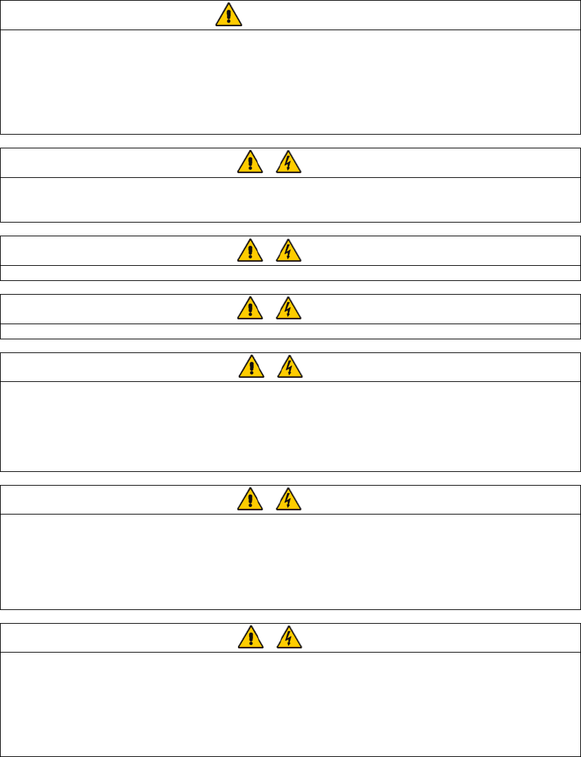
This section describes the operating principle of an individual module. The UPS basically operates as an AC-DC-AC
converter (see Figure 1-1). The first conversion stage (from AC to DC) uses a 3-phase, fully controlled
silicon-controlled resistor (SCR) bridge rectifier to convert the incoming mains supply into a regulated DC busbar.
Rectifier Inverter Static switch
Battery
Bypass AC
supply
Rectifier
AC supply
UPS AC
output
Figure 1-1 Single module block diagram
The DC busbar produced by the rectifier provides both battery charging power – being equipped with a temperature
compensated battery charging system, to prolong battery life – and power to the inverter section – which utilizes the
latest integrated gate bipolar transistor (IGBT) switching space vector pulse width modulation (SVPWM) design – and
provides the second conversion phase, that is, reconverting the DC busbar voltage back into an AC voltage
waveform.
During normal operation, both the rectifier and inverter sections are active and provide regulated load power whilst
simultaneously charging the battery. In the event of a mains power failure, the rectifier becomes inoperative and the
inverter is powered solely from the battery. Critical load power is maintained under these conditions until the battery is
fully discharged, whereupon the UPS shuts down. The end of battery discharge is assumed when the battery voltage
falls below a preset value (that is, 330Vdc for a 400Vac system).
The period for which the load can be maintained following a mains power failure is known as the system’s “Autonomy
Time” and is dependent upon both the battery A/Hr capacity and the applied percentage load.
2 Chapter 1 General Description
HIPULSE U UPS Single Module And “1+N” (Expandable) 160/200/300/400kVA User Manual
1.2.2 Bypass Supplies
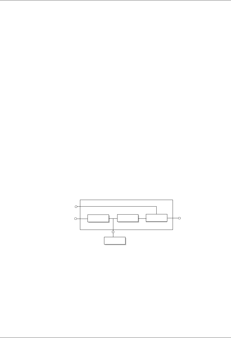
The circuit block annotated “Static switch” in Figure 1-2 contains an electronically controlled switching circuit, which
enables the critical load to be connected either to the inverter output or to a bypass power source through the static
bypass line. During normal system operation, the load is connected to the inverter, and the inverter-side of the static
switch is closed. But in the event of a UPS overload or inverter failure, it is automatically transferred to the static
bypass line.
Bypass
mains supply
Input mains
supply
Maintenance bypass switch Q3
Bypass switch Q2
Rectifier
DC bus
Input switch Q1
Battery circuit breaker
Output switch Q5 UPS output
Inverter Static switch
Battery
C.B.
UPS
Figure 1-2 UPS power switches configuration
To provide a clean (no-break) load transfer between the inverter output and static bypass line, the static switch
activates connecting the load to the bypass supplies. To achieve this, the inverter output and bypass supply must be
fully synchronized during normal operating conditions. This is achieved through the inverter control electronics, which
make the inverter frequency track that of the static bypass supply provided that the bypass remains within an
acceptable frequency window.
A manually controlled, maintenance bypass supply is also incorporated into the UPS design. Its purpose is to enable
the critical load to be powered from the mains (bypass) supply while the UPS is shut down for routine maintenance.
Note: The load equipment is not protected from normal supply aberrations when operating on bypass side or in the
maintenance bypass mode.
1.2.3 System Control Philosophy
Normal operation
During normal operation, that is, when the UPS input supply is present and within specification, both the rectifier and
inverter sections are active and the static switch is turned on to connect the inverter output to the critical load busbars.
The battery circuit breaker (BCB) is also closed and the battery is therefore permanently float charged at the DC
busbar voltage level.
(“1+N” parallel UPS system) Note: As the unit outputs are connected in parallel, the system checks that the inverter
control circuits are perfectly synchronized with one another and with the bypass mains in terms of both frequency and
phase and that they have the same output voltages. Current supplied to the load is automatically divided among
UPSs. A warning message appears while synchronization is in progress.
A module's static switch cannot close until these conditions are satisfied.
Mains failure
If the power mains has a failure or is out of tolerance the rectifier will go off automatically, while the inverter will
continue to operate on power from the battery for a period of time which depends on the load and the capacity of the
battery. If the mains supply has not returned within this time, the inverter will go off automatically and an alarm
message will appear on the operator control and display panel of the UPS.
Critical load will not be interrupted in the event of a drop or return of the AC power mains.

Chapter 1 General Description 3
HIPULSE U UPS Single Module And “1+N” (Expandable) 160/200/300/400kVA User Manual
Return of power mains
When the mains returns within the required tolerance, the rectifier will start up again automatically and gradually
(power walk-in), supplying power to the inverter and recharging the battery at the same time. There will be no
interruption of the critical load.
Off-battery
If the battery system only is taken out of service for maintenance, it is disconnected from the rectifier/charger and
inverters by means of (an) external disconnect breaker(s). The UPS shall continue to function and meet all of the
specified steady-state performance criteria, except for the power outage back-up time capability.
UPS module fault
In the event of an inverter fault, the static transfer switch will automatically transfer the load onto the bypass mains
with no interruption. In such an event, seek technical assistance from Emerson local customer service center.
(“1+N” parallel UPS system) In the event of a fault in a unit, the unit’s static transfer switch will automatically
exclude the unit from the system. If the system is still capable of providing the required load, the remaining units will
continue to supply the load with no interruption. When the units still present in the system are no longer capable of
fulfilling power requirements, the load will automatically be transferred onto the bypass mains.
Overload
In the event of an overload at the inverter output which lasts longer than the typical time/current (refer to table 8-6),
the inverter will shut down and the static transfer switch will automatically transfer the load onto the bypass mains
with no interruption. If the overload falls within the typical time/current that has been specified, the load will be
returned to the inverters when the power drops to a level which can be supported by the number of active units in the
system (parallel “1+N”).
In the event of a short circuit in the output, the load will normally be transferred onto the bypass mains, which will
cause the inverter to shut down. This switch is determined above all by the features of the protective devices in use in
the system.
In either case, an alarm message will appear on the operator control and display panel of the UPS.
(“1+N” parallel UPS system) The control logic system constantly monitors load requirements and controls the power
supplied by the UPS modules. In the event that an overload condition is sustained for greater than a preset time, the
load will transfer to the bypass mains supply, when the number of active modules is unable to satisfy load
requirements. The load returns to the inverter supply if the power is reduced to a value that can be sustained by the
number of active modules in the system.
Maintenance bypass
A second bypass circuit contained in the UPS cabinet, identified as the maintenance bypass line, is included to
enable a raw mains supply to be made available to the load while facilitating a safe working environment for carrying
out scheduled UPS system maintenance or trouble shooting. The circuit is manually selected by the maintenance
bypass switch in the OFF position.
Warning
The internal maintenance bypass must not be used when the UPS system is comprised of more than two UPS modules in
parallel.
CAUTION: If an automatic circuit breaking device is not present in the input distribution panel, there remains a dangerously high
voltage at the output busbars and also on the input busbars of the UPS module that is switched off.
1.2.4 ECO Mode (For Single UPS Only)
In ECO mode, the system prefers to put the load on the bypass mains, with the inverter on stand-by. The load is
switched over to the inverter when the mains goes outside of standard frequency and voltage values (settable).
The ECO mode configuration requires a different setup in the default menu configuration.

4 Chapter 1 General Description
HIPULSE U UPS Single Module And “1+N” (Expandable) 160/200/300/400kVA User Manual
Operating procedures in ECO mode are the same as those described in Chapter 5 Operating Instructions, except
that the load is normally on the bypass mains, the Inverter LED is normally off, and the corresponding alarm message
Bypass mode will appear on the LCD.
Warning
In ECO mode the load is not protected against mains distortion.
1.2.5 UPS Power Switch Configuration
Figure 1-2 illustrates the HIPULSE U UPS module in what is known as the split bypass configuration. In the split
bypass configuration, the static bypass line is connected by a separate power switch to a dedicated bypass power
source which also feeds the maintenance bypass line. Where a separate power source is not available the bypass
(Q2) and rectifier (Q1) input supply connections would be linked together.
With the exception of the maintenance bypass switch, all the switches shown must be closed during normal UPS
operation.
1.2.6 Battery Circuit Breaker
The battery should be connected to the DC busbar through a circuit breaker fitted inside the battery cabinet — or
located adjacent to the batteries where a battery cabinet is not used. This circuit breaker is closed manually, but it
contains an undervoltage release coil which enables it to be tripped from the UPS control electronics following certain
detected faults. It also has a magnetic trip facility for overload protection.
1.2.7 Battery Temperature Compensation
HIPULSE U UPS system offers a battery temperature compensation circuit. As the temperature inside the battery
cabinet/area rises, the DC busbar voltage reduces in order to sustain the battery at its optimum charge voltage. This
must be used in conjunction with the battery temperature sensing device.
1.2.8 System Expansion
If necessary, a single module system can be expanded to cater for an increased load requirement by adding
additional modules — up to a maximum of six UPS modules can be connected in parallel.
System expansion requires a change in the SETUP of the operator control and display panel of each UPS module.
Note:
1. System expansion should be carried out only by trained service personal.
2. The individual modules connected to the system must be of the same power rating.
1.3 Operation Mode
The UPS permits operation in the following alternative modes:
Normal mode
The UPS inverter continuously supplies the critical AC load. The rectifier/charger derives power from the AC mains
input source and supplies DC power to the inverter while simultaneously float or boost charging its associated backup
battery.
Battery mode
Upon failure of the AC mains input power, the critical AC load is supplied by the inverter, which obtains power from
the battery. There is no interruption in power to the critical load upon failure or restoration of the AC mains input
power after which the Normal mode operation will continue without the necessity of user intervention.
Note: Battery start device (optional) is available for switching the UPS on into Battery (charged) mode directly during
mains failure.

Chapter 1 General Description 5
HIPULSE U UPS Single Module And “1+N” (Expandable) 160/200/300/400kVA User Manual
Auto-restart mode
The battery becomes exhausted following an extended AC mains failure. The inverter shuts down when the battery
reaches the end-of-discharge voltage (EOD). The UPS can be programmed to Auto Recovery after EOD after a set
variable delay time. This mode and any delay time are programmed by the commissioning engineer.
Bypass mode
The load power is supplied though the mains static bypass line. This may be considered as an intermediate operating
condition being utilized for the purpose of load transfers between inverter and maintenance bypass or supply under
abnormal operating conditions.
Maintenance mode
The UPS is shut down but the load is connected to the unprotected mains through the maintenance bypass supply
line.
Source Share mode
The UPS has the capability of fully supporting their critical load while limiting the amount of power taken from the
incoming AC mains supply. Any balance of power required is supplied by the UPS battery. This feature is useful, for
example, in applications where peak-hour tariffs apply or where a generator smaller than needed feeds the UPS
during mains outages. The Source Share mode is user-activated and the ratio of the mains AC input power is
programmable from 20% to 100% of the rated UPS power.
ECO mode (for single UPS only)
All power switches and the BCB are closed, the system prefers to put the load on the bypass mains, with the inverter
on stand-by; only when the voltage and/or frequency of the bypass supply are beyond pre-defined and adjustable
limits is the critical AC load transferred to the inverter.
Parallel redundancy mode (system expansion)
For higher capacity or higher reliability or both, the outputs of up to six UPS modules can be programmed for directly
paralleling while a built-in parallel controller in each UPS ensures automatic load sharing.
Frequency converter mode
The UPS can be programmed into Frequency Converter mode for either 50Hz or 60Hz stable output frequency. The
input frequency may vary from 45Hz to 65Hz. In this mode, it is required to open the bypass switch to disable the
static bypass operation, and the battery becomes optional depending on any requirement to operate in Battery mode.
6 Chapter 2 Mechanical Installation
HIPULSE U UPS Single Module And “1+N” (Expandable) 160/200/300/400kVA User Manual
Chapter 2 Mechanical Installation
This chapter briefly introduces the mechanical installation of the HIPULSE U UPS, including the notes, environmental
considerations, mechanical considerations, preliminary checks and installation drawings.
2.1 Notes
Warning
Do not apply electrical power to the UPS equipment before the arrival of the commissioning engineer.
Warning
The UPS equipment should be installed by a qualified engineer in accordance with the information contained in this chapter and
all equipment not referred to this manual is shipped with details of its own mechanical and electrical installation.
Warning: battery hazards
Special care should be taken when working with the batteries associated with this equipment. When connected together, the
battery terminal voltage will exceed 400Vdc and is potentially lethal.
1. Eye protection should be worn to prevent injury from accidental electrical arcs.
2. Remove rings , watches and all metal objects.
3. Only use tools with insulated handles.
4. Wear rubber gloves.
5. If a battery leaks electrolyte, or is otherwise physically damaged, it must be replaced, stored in a container resistant to sulfuric
acid and disposed of in accordance with local regulations.
6. If electrolyte comes into contact with the skin the affected area should be washed immediately with water.
Warning
The UPS system can be connected to an isolated neutral (IT) power system.
This chapter describes the environmental requirements and mechanical considerations that must be taken into
account when planning the positioning and cabling of the UPS equipment.
Because every site has its peculiarities, it is not the aim of this chapter to provide step-by-step installation instructions,
but to act as a guide as to the general procedures and practices that should be observed by the installing engineer.
2.2 Environmental Considerations
2.2.1 UPS Location
The UPS module should be located in a cool, dry, clean-air environment with adequate ventilation to keep the
ambient temperature within the specified operating range (see Table 8-2).
All models in the HIPULSE U UPS range are cooled with the aid of internal fans. Cooling air enters the module
through ventilation grills located at various parts of the cabinet and exhausted through grills located in the cabinet roof.
When the cabinet is located on a raised floor, and bottom cable entry is used, additional cooling air also enters the
UPS through the floor void. If necessary, a system of extractor fans should be installed to aid cooling-air flow, and a
suitable air filtration system used where the UPS is to operate in a dirty environment.
Note:
1. When batteries are cabinet-mounted adjacent to the UPS module, it is the battery which dictates the designed
maximum ambient temperature, not the UPS.
2. Power losses from the system which may be used in an air conditioning system are intended for operation using
the inverter, as in the ECO mode configuration they would be undersized.
Chapter 2 Mechanical Installation 7
HIPULSE U UPS Single Module And “1+N” (Expandable) 160/200/300/400kVA User Manual
2.2.2 Battery Location
Temperature is a major factor in determining the battery life and capacity. Battery manufacturers quote figures for an
operating temperature of 20°C. Operating above this temperature will reduce the battery life, and operation below this
temperature will reduce the battery capacity. On a normal installation the battery temperature is maintained between
15°C and 25°C. Batteries should be mounted in an environment where the temperature is consistent and even over
the whole battery. Keep batteries away from main heat sources or main air inlets, and so on.
The batteries can be mounted in a purpose-built battery cabinet, which is positioned adjacent to the UPS module.
Pedestals are required for the battery cabinets when they are located on raised floors, in the same way as for the
UPS cabinets If the batteries are rack-mounted, or otherwise located remote to the main UPS cabinet, a BCB must
be mounted as close as possible to the batteries themselves, and connected using the most direct route possible.
2.3 Mechanical Considerations
2.3.1 System Composition
A UPS system can comprise a number of equipment cabinets, depending on the individual system design
requirements, for example, UPS cabinet, battery cabinet. The 300kVA UPS (12-pulse rectifier) and 400kVA UPS
comprise a main cabinet and a side cabinet. In general, all the cabinets used in a particular installation are of the
same height and designed to be positioned side-by-side to form an aesthetically appealing equipment suit.
2.3.2 Moving The Cabinets
Warning
Ensure that any lifting equipment that used in moving the UPS cabinet has sufficient lifting capacity.
Ensure that the UPS weight is within the designated surface weight loading of any handling equipment. See Table 8-3
for UPS weight details.
The UPS cabinet can be moved by fork lift. Before moving the UPS cabinet, it is necessary to remove both the front,
rear (or side) grille panels located at the base of the cabinet.
In the eventuality that the equipment cannot be moved by fork lift, then rollers should be used.
2.3.3 Clearances
As HIPULSE U UPS has no ventilation grills at either the sides or the rear, no clearances are required. However,
where space permits, a clearance of approximately 600mm at the back will ease access to magnetic component parts.
Clearance around the front of the equipment should be sufficient to enable free passage of personnel with the doors
fully opened.
2.3.4 Fixing Of The Magnetic Components
Before the equipment is in place, remove the transportation restraints that hold the output transformer in place. For
procedures, refer to Appendix 1 Transportation Restraints Removing Procedures.
2.3.5 Cable Entry
Cables can enter for HIPULSE U UPS and battery cabinet either from below or through either side.
Side entry is made possible by removing blanking pieces fitted in the side panel to reveal the cable entry holes.
This cable entry method allows the equipment to be positioned on a solid floor without the need for cable trenching
and allows cables to pass from one module to the other when positioned side-by-side.
Optionally a top cable entry extension may be used.
Note: When selecting the power cables for side entry to a module located on a solid floor, consideration must be
given to the minimum permissible radius of the proposed cables to ensure that they can be fashioned to reach the
UPS connection busbars.
8 Chapter 2 Mechanical Installation
HIPULSE U UPS Single Module And “1+N” (Expandable) 160/200/300/400kVA User Manual
2.4 Preliminary Checks
Before you install the UPS hardware you should carry out the following preliminary checks:
1. Verify that the UPS room satisfies the environmental conditions stipulated in the equipment specification, paying
particular attention to the ambient temperature, air exchange system, and dust density.
2. Remove any packaging debris, visually examine the UPS and battery equipment for transit damage, both internally
and externally. Report any such damage to the shipper immediately.
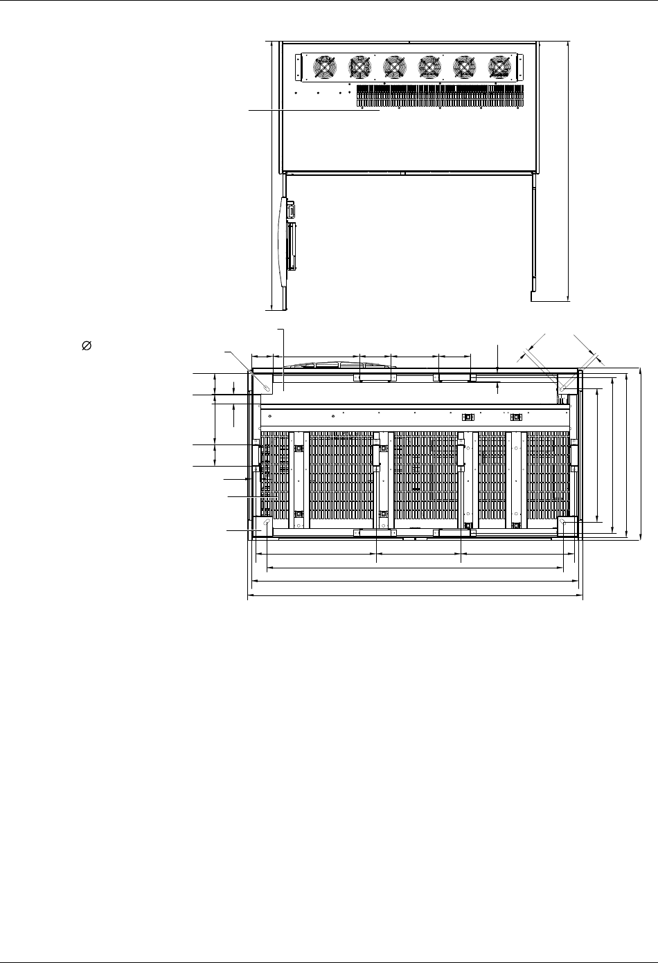
2.5 Installation Drawings
The following drawings illustrate the key mechanical characteristics of the various UPS system cabinets.
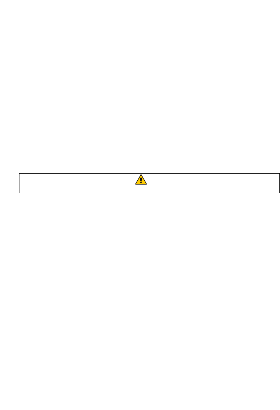
Front view Side view
Top view
Back view
Removable grille for lifting with fork-lift
truck (1 pcs in 1201*116, 2 pcs in 484*102)
1251
Air inlet
Removable grille - if using side
cable entry (2 pcs in 628*102)
87
3
1905
Removable grille for lifting with fork-lift truck
(1 pcs in 1201*116, 2 pcs in 484*102)
Air
outlet
Figure 2-1 Front, side, top, back views of 160kVA/200kVA UPS (6-pulse rectifier) (unit in mm)
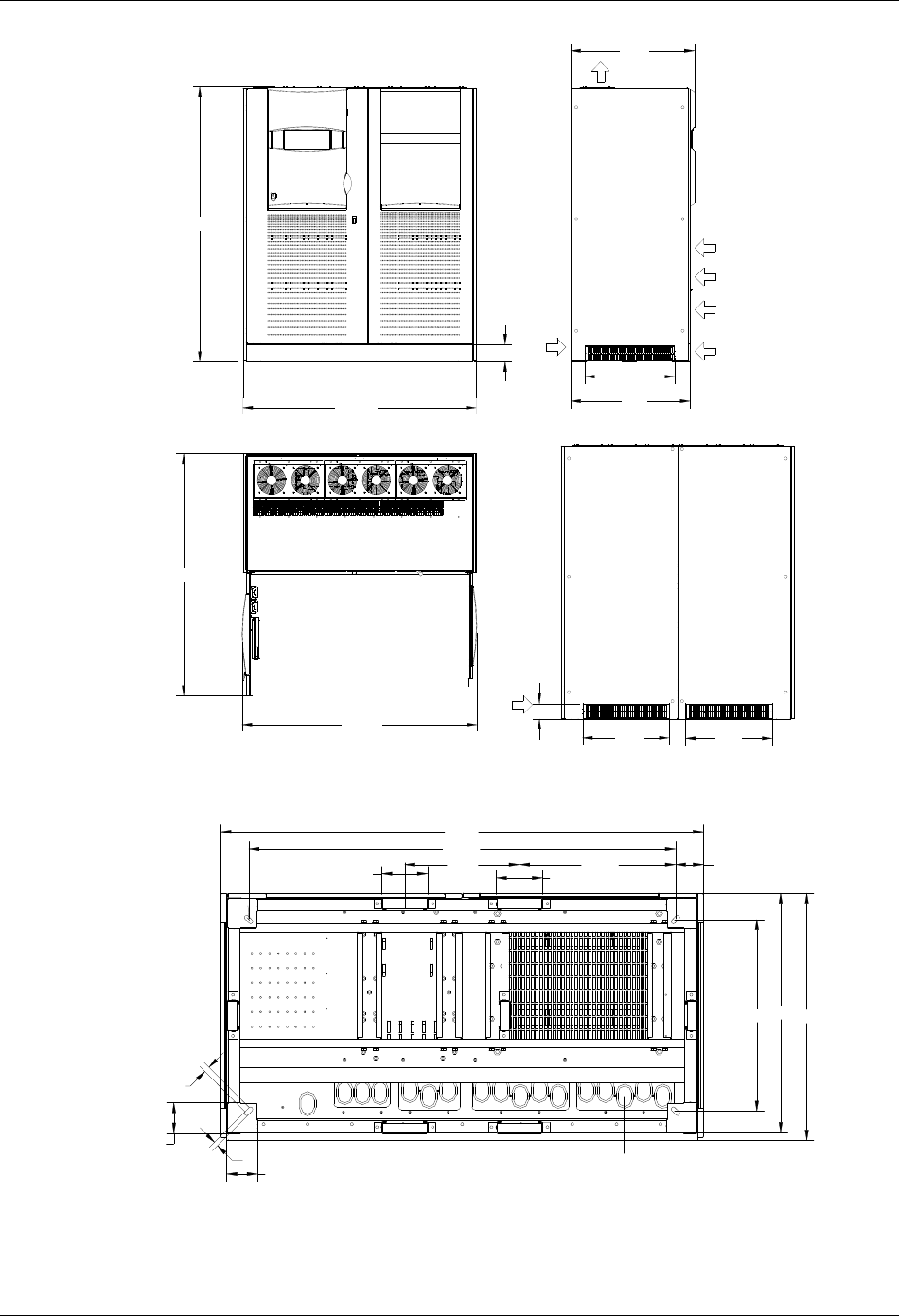
Chapter 2 Mechanical Installation 9
HIPULSE U UPS Single Module And “1+N” (Expandable) 160/200/300/400kVA User Manual
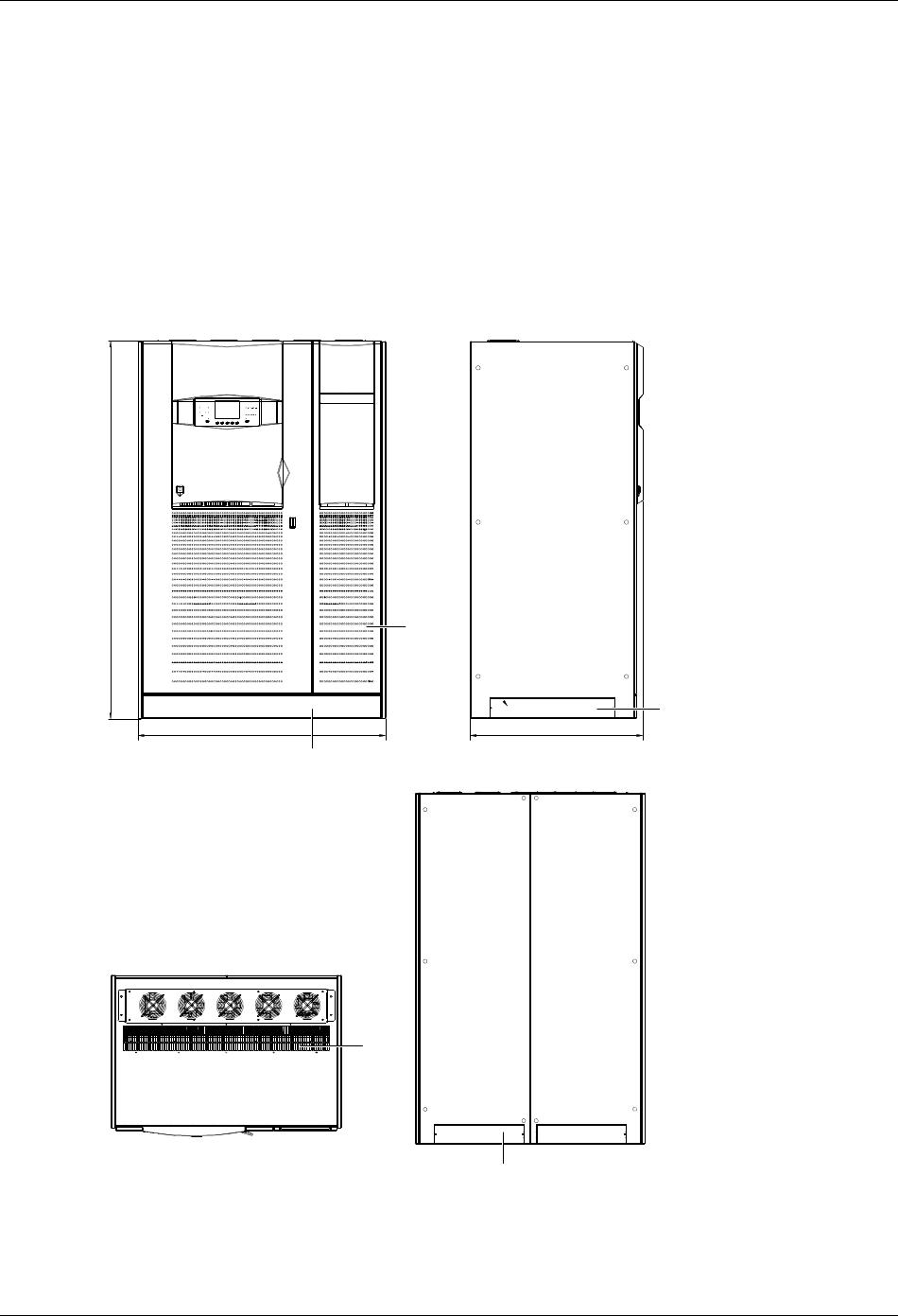
Top view
Base view
Air outlet
1685
1197
843
40
104 424 155
40
103
104
244105
46
14 holes for securing unit to
floor (if required)
Grille for air entry from the bottom
Surface loading of UPS 4×104cm ,2.7Kg\cm
22
1251
615 556
1061
1210
651
761
800
15
20
Cable access
Figure 2-2 Top, base views of 160 kVA/200kVA UPS (6-pulse rectifier) (unit in mm)
10 Chapter 2 Mechanical Installation
HIPULSE U UPS Single Module And “1+N” (Expandable) 160/200/300/400kVA User Manual
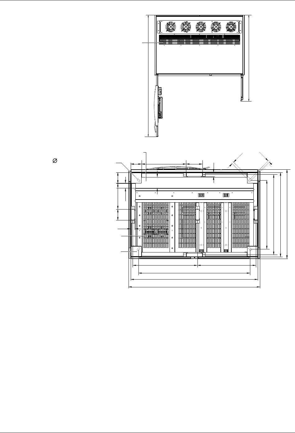
Front view Side view
Back view
Top view
1903
Removable grille for lifting with fork-lift truck
(1 pcs in 1591*116, 2 pcs in 607*102)
1641 873
Air
inlet
Removable grille - if using side
cable entry (2 pcs in 628*102)
Removable grille for lifting with fork-lift truck
(1 pcs in 1591*116, 2 pcs in 607*102)
Air outlet
Figure 2-3 Front, side, top, back views of 160 kVA/200kVA UPS (12-pulse rectifier) (unit in mm)
Chapter 2 Mechanical Installation 11
HIPULSE U UPS Single Module And “1+N” (Expandable) 160/200/300/400kVA User Manual
Top view
Air outlet
1685
1626
Base view
155
104 424 155 235
843
104244
46
105
651
761
800
40
14 holes for securing unit to
floor (if required)
Cable access
Grille for air entry from the bottom
Surface loading of UPS 8×104cm ,2.0Kg\cm
22
40
1641
590 415 556
1451
1600
20
15
Figure 2-4 Top, base views of 160 kVA/200kVA UPS (12-pulse rectifier) (unit in mm)
12 Chapter 2 Mechanical Installation
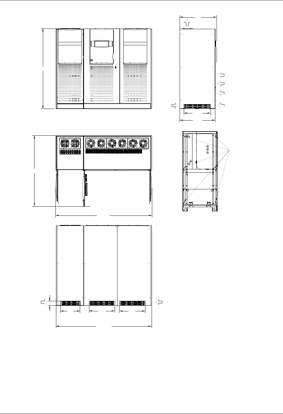
HIPULSE U UPS Single Module And “1+N” (Expandable) 160/200/300/400kVA User Manual
>1685
>1655
1641
1910
843
632
108
610
873
610
正视图
俯视图
侧视图
120
口进风
出口风
可拆卸 板栅 1591*116 1件(卸下 板可栅
用于叉 搬运车, 安装后可用于防 通护风)
可拆卸 板栅
607*102两件
可拆卸 板栅
628*102 1件
后
视图
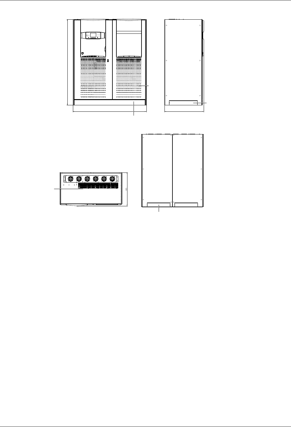
Front view
Side view
Air outlet
Air inlet
Removable
grille (2 pcs
in 628*102)
Removable grille (1 pcs in 1591*116, for
lifting with fork-lift truck after being removed,
for protection and ventilation after being
installed)
Top view
Back view
Removable
grille (2 pcs
in 607*102)
1641
Removable grille (1 pcs in 1591*116, for lifting
with fork-lift truck after being removed, for
protection and ventilation after being installed)
Figure 2-5 Front, side, top, back views of 300kVA UPS (6-pulse rectifier) (unit in mm)
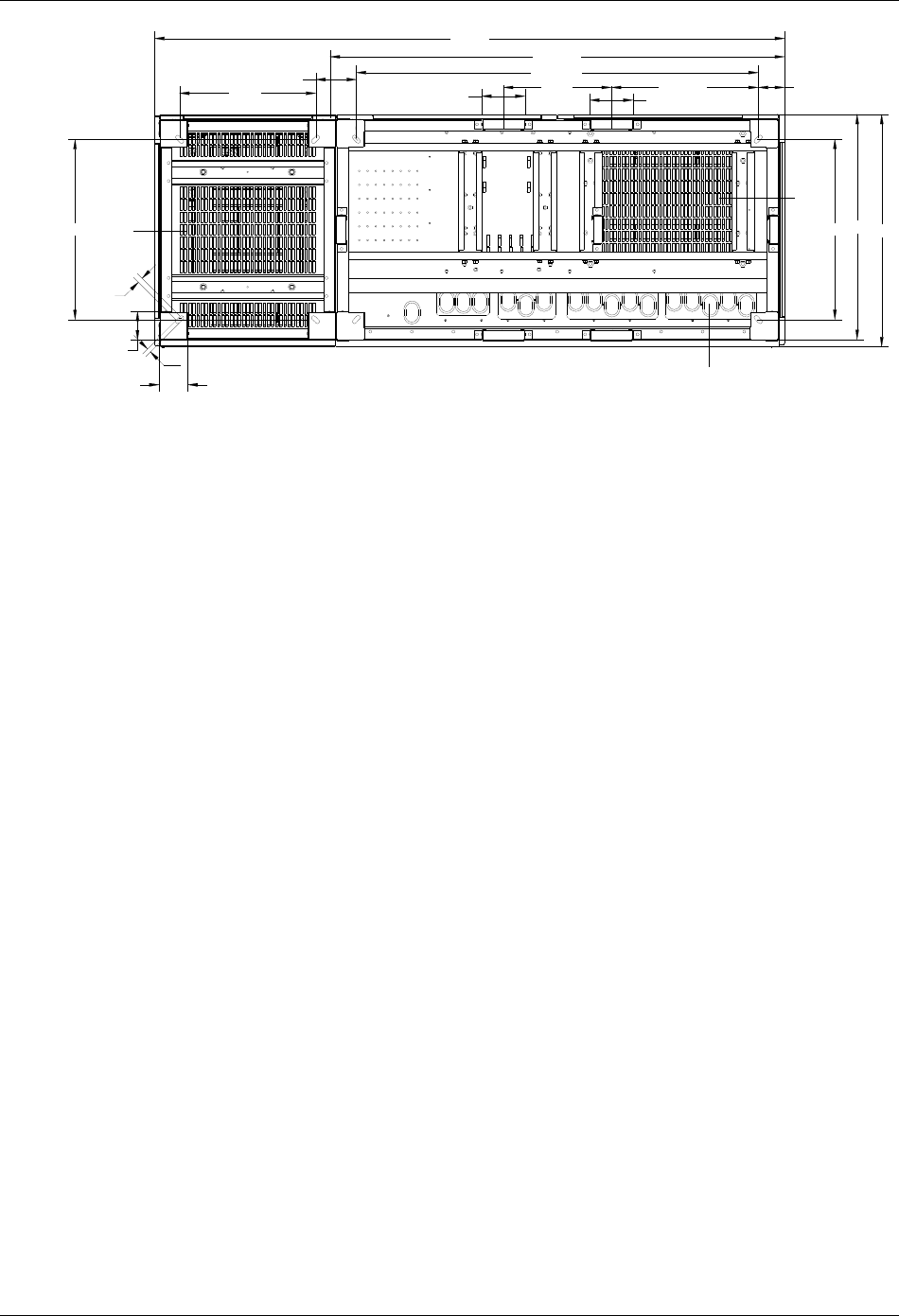
104
104 15 此 孔可用于固定地脚螺栓种长圆
20
前门
156
1641
390
1451
651813 840
156 530.5 95
口进线
底部
通风
孔栅
Ventilation grille
at the bottom
Cable entry holes
Holes for securing unit to floor
Front door
Figure 2-6 Base view of 300kVA UPS (6-pulse rectifier) (unit in mm)
Chapter 2 Mechanical Installation 13
HIPULSE U UPS Single Module And “1+N” (Expandable) 160/200/300/400kVA User Manual
>1685
2293
1910
并柜固定螺栓( 6个)
843
2273. 5
632
口进风
108
467
873
610 610
可拆卸 板栅 1591*116 1件, 631*116 1件
(卸下 板可用于叉 搬运栅车, 安装后可用于防 通护风)
可拆卸 板栅
628*102 1件
可拆卸 板栅
607*102两件
俯视图
后视图
侧视图
正视图 出口风
可拆卸 板栅
464*102 1件
Front view
Side view
Air outlet
Air inlet
Removable grille
(1 pcs in 628*102)
Six fixing bolts for
cabinet parallel
connection
Removable grille (1 pcs in 1591*116, 1 pcs in 631*116,for
lifting with fork-lift truck after being removed, for protection
and ventilation after being installed)
Top view
Back view
Removable
grille (2 pcs
in 607*102)
Removable
grille (1 pcs
in 464*102)
Figure 2-7 Front, side, top, back views of 300kVA UPS (12-pulse rectifier) and 400kVA UPS (6/12-pulse rectifier) (unit in mm)
14 Chapter 2 Mechanical Installation
HIPULSE U UPS Single Module And “1+N” (Expandable) 160/200/300/400kVA User Manual
651
前门
104
104
20
491 148 156
2275
390
1451
1641
156 530.5
651813 840
95
口进线
15 此 孔可用于固定地脚螺栓种长圆
底部
通风
孔栅
底部
通风
孔栅
Ventilation grille at
the bottom
Ventilation grille at
the bottom
Holes for securing unit to floor
Front door Cable entry holes
Figure 2-8 Base view of 300kVA UPS (12-pulse rectifier) and 400kVA UPS (6/12-pulse rectifier) (unit in mm)
Chapter 3 Electrical Installation 15
HIPULSE U UPS Single Module And “1+N” (Expandable) 160/200/300/400kVA User Manual
Chapter 3 Electrical Installation
This chapter introduces the electrical installation of the HIPULSE U UPS, including the procedures or methods for
power cabling and control cabling, and the distance from floor to connection point.
The UPS requires both power cabling and control cabling once it has been mechanically installed. All control cables,
whether screened or not, should be run separate from the power cables in metal conduits or metal ducts which are
electrically bonded to the metalwork of the cabinets to which they are connected.
3.1 Power Cabling
Warning
BEFORE CABLING UP THE UPS, ENSURE THAT YOU ARE AWARE OF THE LOCATION AND OPERATION OF THE
EXTERNAL ISOLATORS THAT CONNECT THE UPS INPUT/BYPASS SUPPLY TO THE MAINS DISTRIBUTION PANEL.
CHECK THAT THESE SUPPLIES ARE ELECTRICALLY ISOLATED, AND POST ANY NECESSARY Warning SIGNS TO
PREVENT THEIR INADVERTENT OPERATION.
For cable entry, refer to 2.3.5 Cable Entry.
3.1.1 System Configuration
The power cables of the system must be size with respect to the following description:
Module input cables
The input cables must be sized for the maximum input current, including the maximum battery recharge current,
given in the Table 3-1, with respect to the module rating and the input AC voltage.
Module bypass and output cables
The bypass and output cables must be sized for the nominal output current, given in the Table 3-1, with respect to the
module rating and the output AC voltage.
Battery cables
Each UPS module has its own battery which is connected using two cables, one positive and one negative. The
battery cables must be sized for the battery discharge current at the end-of-discharge voltage, as given in Table 3-1
with respect to the module rating.
3.1.2 Cable Rating
The power cables can be sized to suit the UPS module rating according to Table 3-1.
Table 3-1 UPS module power cable rating
Nominal current: Amps Busbar stud size
Input mains with full battery recharge
(subtract 5% for 12-pulse) Bypass/output at full load Input/output
cables
UPS rating
(kVA)
380V 400V 415V 380V 400V 415V
Battery at
minimum battery
voltage (400Vac)* Bolt Ø
Battery
cables
Tor qu e
(Nm)
160 341 324 312 243 231 222 464 M10 11 M10 bolt 26
200 426 405 390 304 289 278 580 M10 11 M10 bolt 26
300 634 602 572 456 434 413 870 M12 13 M12 bolt 50
400 848 803 772 607 578 556 1160 M12 13 M12 bolt 50
Note*: Maximum battery discharge current at 380Vac supply increases by 3%, and for a 415Vac supply decreases by 3%
16 Chapter 3 Electrical Installation
HIPULSE U UPS Single Module And “1+N” (Expandable) 160/200/300/400kVA User Manual
3.1.3 General Notes
The following are guidelines only and superseded by local regulations and codes of practice where applicable:
1. The neutral conductor should be sized for 1.5 times the output/bypass phase current.
2. The earth conductor should be sized at 2 times the output/bypass conductor (this is dependent on the fault rating,
cable lengths, type of protection etc.).
3. Consideration should be given to the use of paralleled smaller cables for heavy currents, as this can ease
installation considerably.
4. When sizing battery cables, a maximum volt drop of 3Vdc is permissible at the current ratings given in Table 3-1.
5. In most installations, especially those concerning parallel multi-module systems, the load equipment is connected
to a distribution network of individually protected busbars fed by the UPS output rather than being connected directly
to the UPS itself. Where this is the case the UPS output cables can be rated to suit the individual distribution network
demands rather than being fully load-rated.
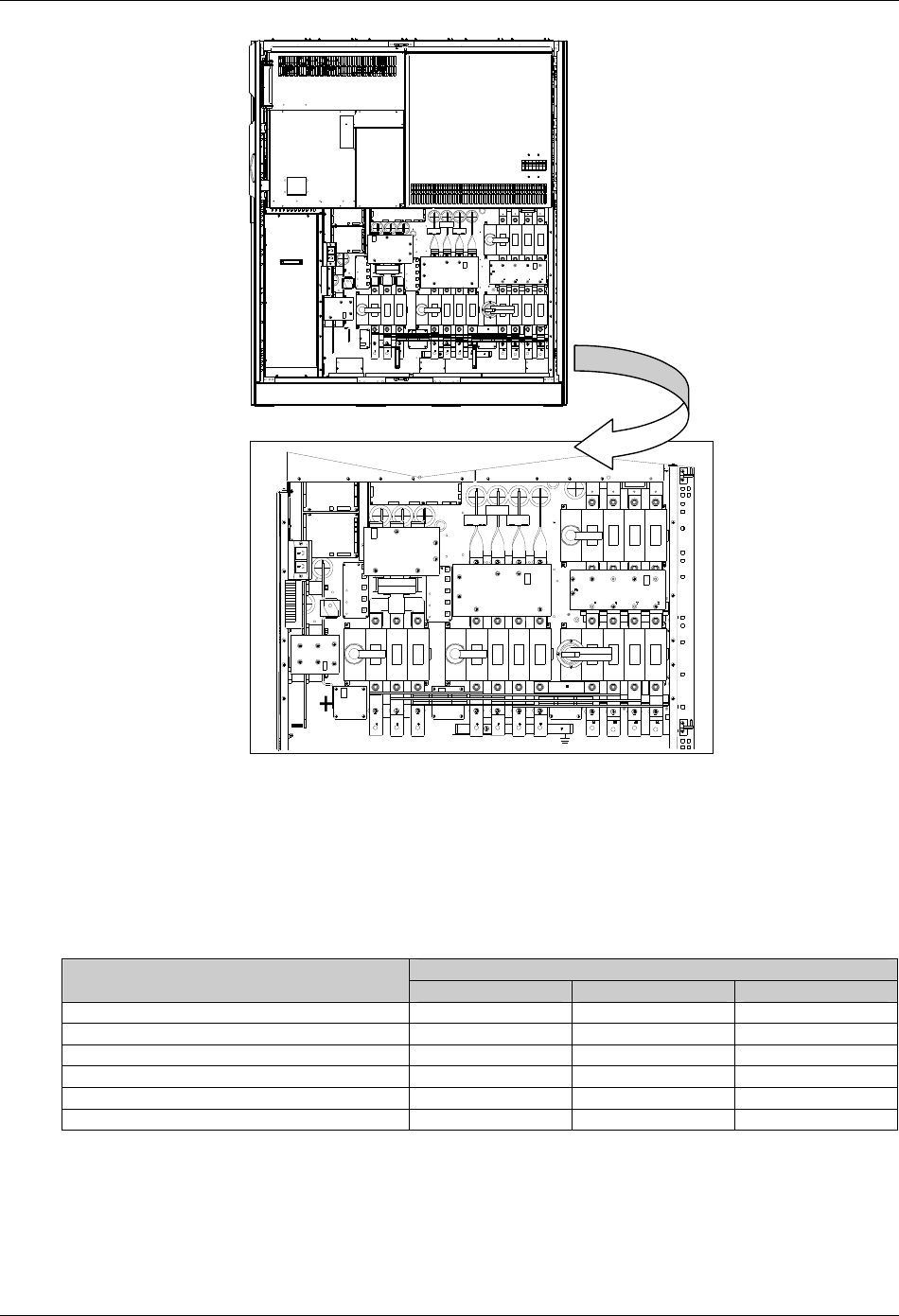
3.1.4 Cable Connections
The rectifier input, bypass, output and battery power cables (all require lug type terminations) are connected to
busbars situated below the power isolator switches, as shown in Figure 3-2 and Figure 3-3.
A terminal block X3 is used for connecting the control cables to the battery circuit breaker (BCB). These are female
spade type connections (fast-on 6.3*0.8) and are described later in 3.3.2 Battery Control.
3.1.5 Safety Earth
The safety earth busbar is located near the input and output power supply connections as shown in Figure 3-2 and
Figure 3-3. The safety earth cable must be connected to the earth busbar and bonded to each cabinet in the system.
All cabinets and cable trunking should be earthed in accordance with local regulations. The earth cable should be
bound with binding strips onto the metallic column for cabling so as to prevent the fixing screw of the earth cable from
loosening in the case the earth cable is pulled.
Warning
FAILURE TO FOLLOW ADEQUATE EARTHING PROCEDURES CAN RESULT IN ELECTRIC SHOCK HAZARD TO
PERSONNEL, OR THE RISK OF FIRE, SHOULD AN EARTH FAULT OCCUR.
3.1.6 Protective Devices
For safety reasons, it is necessary to install, external to the UPS system, circuit breaking protective devices in the
input AC supply and towards the battery. Given that every installation has its own characteristics, this chapter
provides general useful information for qualified installation engineers, with knowledge of operating practices, of
regulatory standards, and of the equipment to be installed.
Rectifier and bypass input supply of the UPS
1. Protection against excessive overcurrents and short circuits in the mains supply input
These inputs must be protected, installing suitable protective devices at the distribution panel of the incoming mains
supply, considering that the protection should discriminate with overload capacity of the system (see Table 8-6 and
Table 8-7).
2. Split bypass
In the case of a split bypass being used, separate protective devices should be installed in the incoming mains
distribution panel. The protective devices must be selected for the nominal input current, with respect to the UPS
rating and the input AC supply voltage as given in Table 3-1.
3. Protection against earth faults
In the event of a residual current detector (RCD) device being installed upstream of the input supply, one must take
into account the transient and steady state earth leakage currents that are produced during start-up of the UPS.
Chapter 3 Electrical Installation 17
HIPULSE U UPS Single Module And “1+N” (Expandable) 160/200/300/400kVA User Manual
The presence of a radio frequency interference (RFI) suppression filter inside the UPS determines a residual earth
current greater than 3.5mA and less than 1000mA.
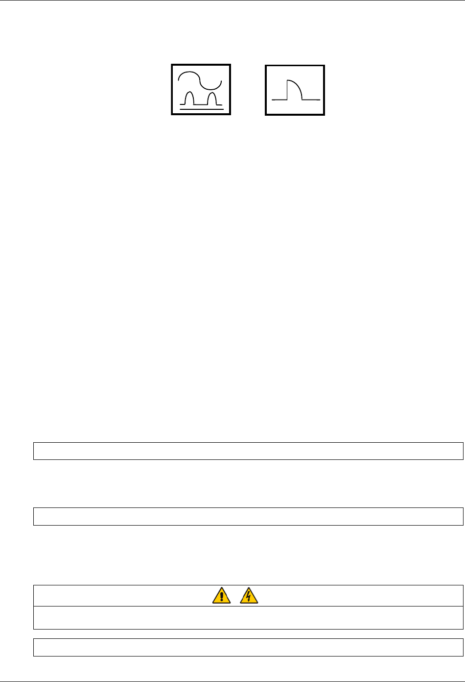
Residual current circuit breakers (RCCBs) must be sensitive to DC unidirectional pulse (Class A) in the network and
insensitive to transient current pulses. They are identified by the symbols respectively:
Figure 3-1 Symbols of residual current circuit breaker (RCCB)
These isolators must have an average sensitivity, possible adjustable between 0.3A and 1A.
It is recommended that the selectivity with every RCD be verified both upstream of the input distribution board and
downstream (towards the load).
UPS battery
The UPS Battery is protected by means of a control circuit that operates the tripping mechanism of an automatic
circuit breaking device (having a variable trip setting). The tripping mechanism using an undervoltage release coil that
operates on a present minimum voltage level.
The circuit breaker is essential for maintenance of the battery and is normally located near to the battery installation.
Output of the system
In the eventuality that an external distribution panel is used for load distribution, the selection of protective device
must provide discrimination with those that are use at the input to the UPS module.
3.1.7 Cabling Procedure
Once the equipment has been finally positioned and secured, refer to Figure 3-2 and Figure 3-3 to connect the power
cables as described in the following procedures:
1. Verify that the UPS equipment is totally isolated from its external power source and all the UPS power isolators are
open. Check that these supplies are electrically isolated, and post any necessary warning signs to prevent their
inadvertent operation.
2. Open the UPS door and remove the lower protective cover to gain access to the connections bars.
3. Connect the safety earth and any necessary bonding earth cables to the copper earth busbar located on the floor
of the equipment below the power connections.
Note: The earthing and neutral bonding arrangement must be in accordance with local and national codes practice.
Common Input Connections
4. For common bypass and rectifier inputs, connect the AC input supply cables between the mains distribution panel
and the UPS input supply busbars (U1-V1-W1-N1 terminals) and tighten the connections to 13 Nm (M8 bolt), and to
26 Nm (M10 bolts). ENSURE CORRECT PHASE ROTATION.
Split Bypass Connections
5. If a split bypass configuration is used, connect the AC input supply cables to the input busbars (U1-V1-W1
terminals) and the bypass AC supply cables to the bypass busbars (U2-V2-W2-N2 terminals) and tighten the
connections to 13 Nm (M8 bolt), to 26 Nm (M10 bolt), and to 50 Nm (M12 bolt). ENSURE CORRECT PHASE
ROTATION.
Warning
Ensure that any links (*) fitted between rectifier input and bypass busbars are removed. But do not remove those between the
neutral terminals. See Figure 3-2 and Figure 3-3.
Output System Connections
18 Chapter 3 Electrical Installation
HIPULSE U UPS Single Module And “1+N” (Expandable) 160/200/300/400kVA User Manual
6. Connect the system output cables between the output busbars (N3-U3-V3-W3 terminals) and the critical load and
tighten the connections to 13 Nm (M8 bolt), to 26 Nm (M10 bolt), and to 50 Nm (M12 bolt). ENSURE CORRECT
PHASE ROTATION.
Warning
If the load equipment will not be ready to accept power on the arrival of the commissioning engineer then ensure that the system
output cables are safely isolated at their ends.
UPS Battery Connections
7. Connect the battery cables between the UPS terminals (+/-) and its associated BCB. Connect screened auxiliary
cables from each BCB control board to the auxiliary terminal block (X3). OBSERVE THE BATTERY CABLE
POLARITY.
Warning
Do not close the BCB before the equipment has been commissioned.
8. Refit the lower protective cover.
Bypass
connections
Battery
connections
Rectifier
connections Earth Output
connections
Auxiliary
terminal block
Note: For split bypass operation,
ensure that the busbars (*)
between the bypass input and
rectifier input are removed.
Figure 3-2 Power cable connections for 160/200kVA UPS
Chapter 3 Electrical Installation 19
HIPULSE U UPS Single Module And “1+N” (Expandable) 160/200/300/400kVA User Manual
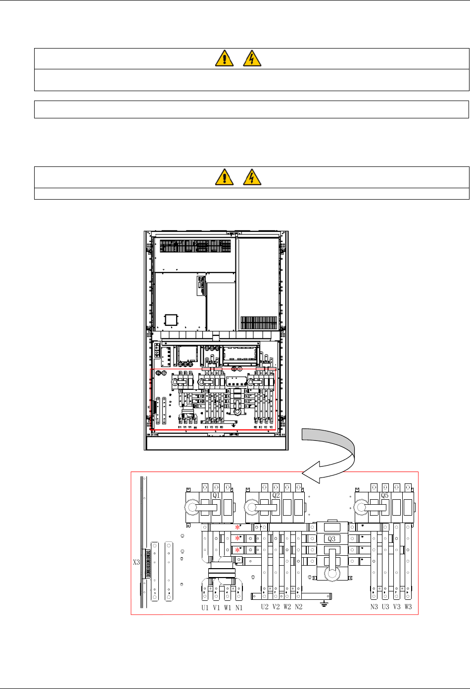
U1
X3
Q1
Q5
W2
V1 W1 V3U3
N3 W3
V2
U2
Q2 Q3
N2
助端子辅
接盒线
池接电连 整流器 接连旁路 接连出接输连
接地
注: 如采用分离旁路, 拆请
除旁路和整流器 入之 的输间
三个横向跨接母线(*)
***
Auxiliary
terminal block
Battery
connections
Rectifier
connections
Bypass
connections Earth Output
connections
Note: For split bypass operation,
ensure that the three horizontal
busbars (*) between the bypass
input and rectifier input are removed.
Figure 3-3 Power cable connections for 300/400kVA UPS
3.2 Distance From Floor To Connection Point
The distances from floor to connection points are provided in Table 3-2.
Table 3-2 Distance from floor to connection point
Minimum distance (mm)
UPS 160/200kVA 300kVA 400KVA
Rectifier AC input supply 247.5 273 273
Bypass AC input supply 247.5 273 273
UPS AC output 247.5 267.5 273
Battery power 244 300 305
Battery control and temperature compensation 325 350 350
Ground 247.5 270 274
20 Chapter 3 Electrical Installation
HIPULSE U UPS Single Module And “1+N” (Expandable) 160/200/300/400kVA User Manual
3.3 Control Cabling
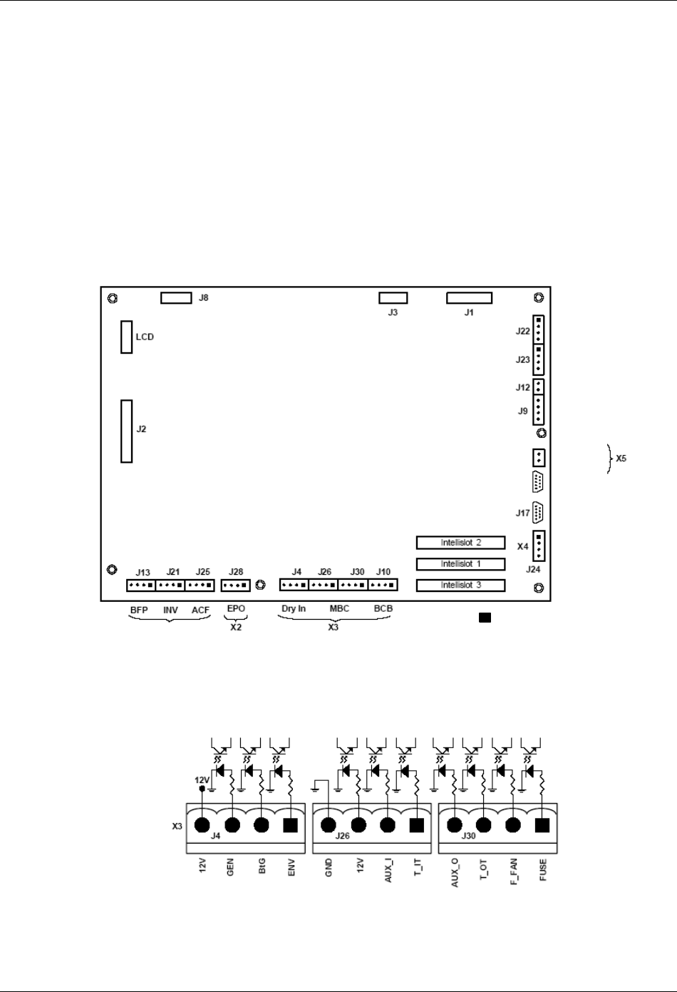
3.3.1 Monitoring Board Ports
Based on your site’s specific needs, the UPS may require auxiliary connections to manage the battery system,
communicate with a personal computer or provide alarm signaling to external devices or for remote Emergency
Power Off (EPO). The monitor board, arranged for this purpose, is located on the rear of the operator access door. As
shown in Figure 3-4, it provides the following ports:
z dry contact input ports (X3)
z dry contact output ports (X1)
z emergency Power Off (EPO) input port (X2)
z auxiliary DC power output port (X5)
z communication ports: serial ports RS232-1 and RS232-2, Intellislot ports
MODEM/
SNMP卡电
源
黑方块( )代表引脚1
X1
J15
J16
RS232-2
RS232-1
) on each slotThe black square (
indicates Pin 1.
PWR
Modem
SNMP
card
Figure 3-4 Ports of the monitoring board
Dry contact input ports (X3)
The dry contact input ports (X3) include a battery environment, battery ground fault and generator supply detection
port (J4) and a maintenance bypass cabinet port (J26, J30), as shown in Figure 3-5.
Figure 3-5 Dry contact input port
Chapter 3 Electrical Installation 21
HIPULSE U UPS Single Module And “1+N” (Expandable) 160/200/300/400kVA User Manual
1. Battery environment, battery ground fault and generator supply detection port (J4)
The battery environment, battery ground fault and generator supply detection port is described in Table 3-3.
Table 3-3 Description of battery environment, battery ground fault and generator supply detection port
Position Name Description
J4.1 ENV3 Battery environment detection (NC)
J4.2 BtG Battery ground fault detection (NC)
J4.3 GEN1,2 On generator (NO)
J4.4 +12V +12V power
Note:
1. Must be configured by configuration software before becoming active.
2. When activated, the charger current can be limited, through software, to a percentage of the full charger current (0~100%).
3. Activating this feature will limit the battery charging
The UPS accepts external signaling from voltage-free (dry) contacts connected to finger-proof, push-in terminal J4.
Subject to prior software programming, the signaling is accepted by the UPS when connection between the relevant
terminal and the +12V terminal of J4 is altered. Cables connected to J4 must be segregated from power circuits (for
screening purposes), double insulated and of a typical 0.5 to 1mm2
cross-section area for maximum runs between 25
and 50 meters, respectively.
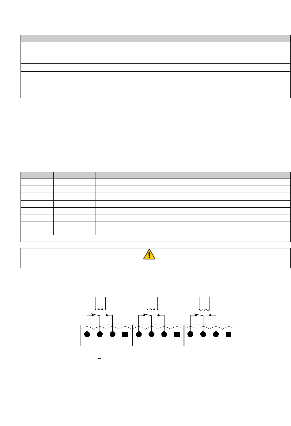
2. Maintenance bypass cabinet port (J26, J30)
J26 and J30 are the maintenance bypass cabinet (MCB) port. The ports are described in Table 3-4.
Table 3-4 Description of maintenance bypass cabinet port
Position Name Description
J26.1 T_IT* Input transformer overtemperature (NC)
J26.2 AUX_I (Reserved)
J26.3 +12V +12V power
J26.4 GND Power ground
J30.1 FUSE (Reserved)
J30.2 F_FAN Fan fail alarm (NC)
J30.3 T_OT* Output transformer overtemperature (NC)
J30.4 AUX_O (Reserved)
Note*: Must be configured by software before becoming active
Note
All auxiliary cables must be double insulated. Wire should be 0.5~1.5mm2 stranded.
Dry contact output port (X1)
There are three output dry contact relays at the X1 slot, see Figure 3-6 and Table 3-5.
X1 J13 J21 J25
BFP_C
BFP_S
BFP_O
INV_C
INV_S
INV_O
ACF_C
ACF_S
ACF_O
Figure 3-6 Dry contact output port
22 Chapter 3 Electrical Installation
HIPULSE U UPS Single Module And “1+N” (Expandable) 160/200/300/400kVA User Manual
Table 3-5 Description of dry contact output port
Position Name Description
J13.2 BFP_O Bypass feedback protection relay (NO)
J13.3 BFP_S Bypass feedback protection relay center
J13.4 BFP_C Bypass feedback protection relay (NC)
J21.2 INV_O On inverter dry contact relay (NO)
J21.3 INV_S On inverter dry contact relay center
J21.4 INV_C On inverter dry contact relay (NC)
J25.2 ACF_O Main input voltage or frequency fault relay (NO)
J25.3 ACF_S Main input voltage or frequency fault relay center
J25.4 ACF_C Main input voltage or frequency fault relay (NC)
Note
All auxiliary cables must be double insulated. Wire should be 0.5~1.5mm2 stranded.
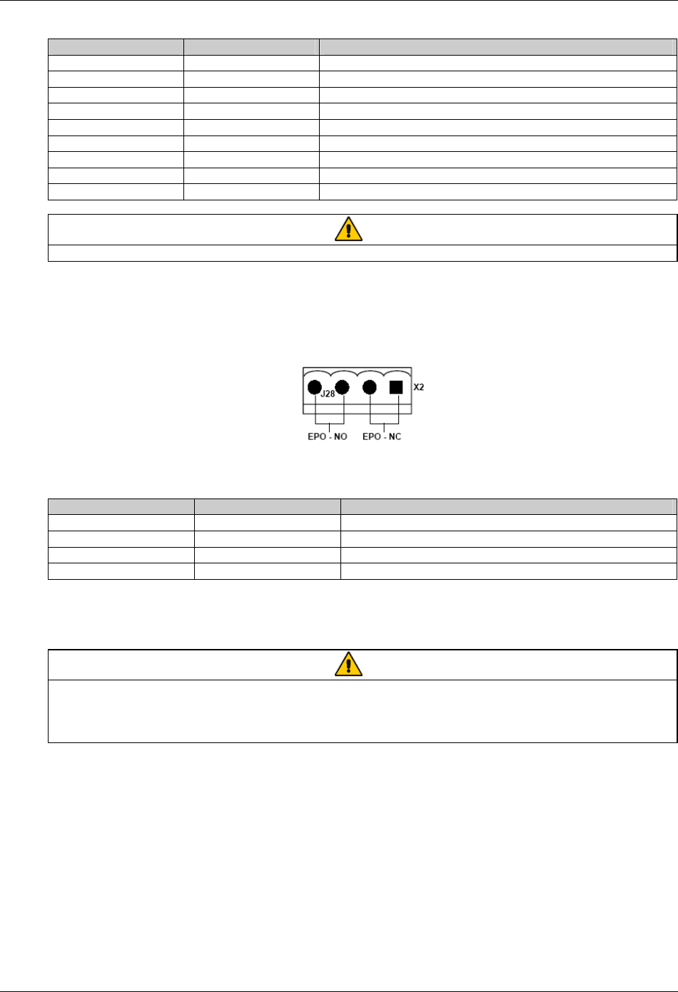
EPO input port (X2)
The UPS has an Emergency Power Off (EPO) function that operates by a button on the UPS door or by a remote
contact provided by the user.
The X2 slot, shown in Figure 3-7, is the remote EPO input port, which is described in Table 3-6.
Figure 3-7 EPO input port
Table 3-6 Description of EPO input port
Position Name Description
J28.1 EPO_NC EPO activated when opened to J28.2
J28.2 EPO_NC EPO activated when opened to J28.1
J28.3 EPO_NO EPO activated when shorted to J28.4
J28.4 EPO_NO EPO activated when shorted to J28.3
The remote EPO facility is connected to the normally open or normally closed remote stop switch between these two
terminals using shielded cable. If this function is not used, terminals J28: 3&4 must be opened and J28: 1&2 must be
closed.
Note
The emergency stop action within the UPS shuts down the rectifier, inverter and static bypass. It does not internally disconnect the
input power supply. To disconnect ALL power to the UPS, open the upstream feeder breaker(s) when the remote EPO is
activated.
Normally closed EPO–J28: 1, 2, these terminals are supplied factory-linked on the monitor board.
Auxiliary DC power output port (X5)
The auxiliary DC power output port X5 provides auxiliary DC power for optional SNMP card. The voltage is between
9V to 12V. The maximum current is 500mA.
Communication ports
The communication ports include the serial ports RS232-1 and RS232-2, Intellislot intelligent communication ports.
1. Serial ports RS232-1 and RS232-2
RS232-1 provides serial data and is intended for direct use with Emerson UPSitePlusTM UPS monitoring software.
RS232-2 provides serial data and is intended for use by authorized commissioning and service personnel.
Chapter 3 Electrical Installation 23
HIPULSE U UPS Single Module And “1+N” (Expandable) 160/200/300/400kVA User Manual
2. Intellislot intelligent communication ports
There are three intelligent communication ports (Intellislot 1, Intellislot 2, and Intellislot 3) available for installing
optional SNMP card, UPS JBUS/MODBUS adapter, and relay card.
The serial ports RS232-1, RS232-2, and the Intellislot intelligent communication ports share the same communication
resources, as described in Table 3-7.
Table 3-7 Communication port resource deployment table
Port
On the UPS
LCD screen, under
Settings, controlled by:
Monitoring devices supported Baud
rate Comments
SNMP card 9600
JBUS/MODBUS adapter Any
Intellislot 2 Comm 1
Relay card Any
Not simultaneous with
RS232-2
SNMP card 9600
JBUS/MODBUS adapter Any
Intellislot 1 Comm 2
Relay card Any
Not simultaneous with
RS232-2
SNMP card 9600
JBUS/MODBUS adapter Any
Intellislot 3 Comm 3
Relay card Any
Not simultaneous with
RS232-2
RS232-1 Comm 1 UPSitePlusTM UPS monitoring software 9600 -
RS232-2 Comm 2
Commissioning and service software (only for use by
authorized commissioning and service personnel) 9600 Not simultaneous with the
three Intellislot ports
3.3.2 Battery Control
The BCB is controlled by the BCB control board. Both are located within the BCB box. This board controls the circuit
breaker's undervolts release coil and also provides a path for the circuit breaker auxiliary contacts to signal the circuit
breaker status back to the UPS control logic.
All connections between the BCB control board and the UPS module are made through the auxiliary terminal block
X3 located on the base of the UPS Cabinet. X3 is shown in Figure 3-8 and described in Table 3-8.
FB
GND
OL
+12V
TMP_T
GND
LM355+
LM355+ GND
DRV
DRV_GND
BCB status feedback
BCB connection detection
Battery temperature sensing 1
Battery temperature sensing 2
BCB drive
Not connected
NC
NC
X3
1
2
3
4
5
6
7
8
9
10
11
12
Figure 3-8 Auxiliary terminal block X3
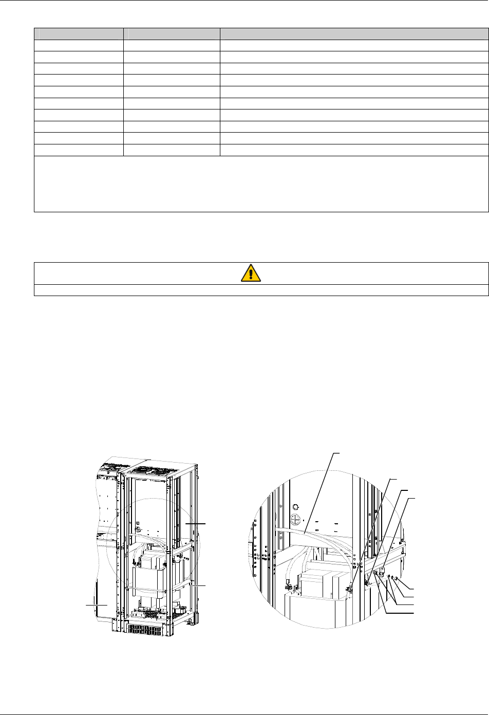
24 Chapter 3 Electrical Installation
HIPULSE U UPS Single Module And “1+N” (Expandable) 160/200/300/400kVA User Manual
Table 3-8 Description of auxiliary terminal block X3
X3 terminal reference Reference label Description
1 FB BCB normally open auxiliary contact
2 GND Signal ground
3 OL Cable detection
4 +12V Power positive
5 TMP_T Temperature sensing terminal
6 GND Temperature sensing signal ground
7 LM355+ LM335 detection positive
8 LM355+GND LM335 signal ground
9 DRV BCB drive
10 DRV_GND Drive ground
Note:
1. The auxiliary cables of the battery must be screened and double insulated.
2. The screen is connected to the earth of the battery cabinet or supporting rack.
3. Use multiple-core shielded cables with a section of 0.5 to 1 mm2.
4. Connect the cables with the fast-on 6.3*0.8 mm terminals (female)
Connect the BCB control and temperature compensation cables between the UPS auxiliary terminal block X3 and
BCB control board. For details, refer to Figure 6-5. These cable must be shielded, shield should be connected at
protective earth of battery cabinet or battery breaker, not of UPS.
Note
If battery temperature compensation is needed, this function must be activated by the commissioning engineer.
3.4 Connecting Main Cabinet And Side Cabinet
The 300kVA UPS (12-pulse rectifier) and 400kVA UPS comprise a main cabinet and a side cabinet.. In installation,
you need to make electrical connection between the main cabinet and side cabinet.
3.4.1 Connecting Power Cables
The power cable connections between the main cabinet and side cabinet of the 300kVA UPS (12-pulse rectifier) and
400kVA UPS are shown in Figure 3-9 to Figure 3-11. The installation engineer should make cable connection in strict
accordance with these figures.
A
W4-2, W5-2, W6-2
W4-2
W5-2
W6-2
Side cabinet
Main cabinet
Nut M10
Spring w asher 10
Plain w asher 10
Bolt M10 *35
A amplified view
Figure 3-9 Power cable connection between main cabinet and side cabinet of 300kVA UPS (12-pulse rectifier)
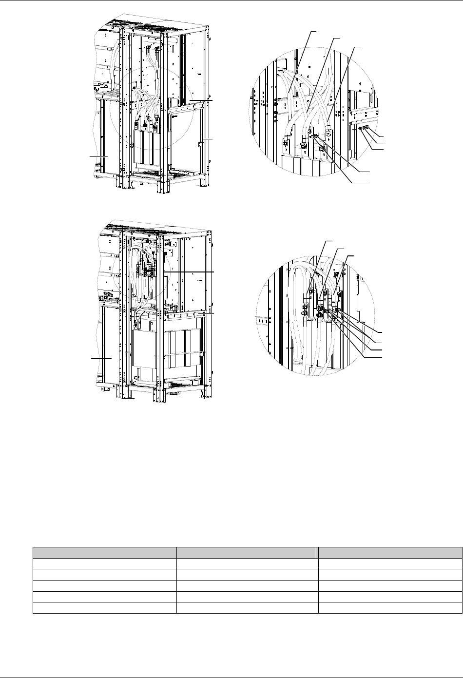
Chapter 3 Electrical Installation 25
HIPULSE U UPS Single Module And “1+N” (Expandable) 160/200/300/400kVA User Manual
A amplified view
A
Side cabinet
Main cabinet
Nut M10
Spring w asher 10
Plain w asher 10
Plain w asher 10
Bolt M10 *35
W6(red)
W5(green)
W4(yellow )
Figure 3-10 Power cable connection between main cabinet and side cabinet of 400kVA UPS (6-pulse rectifier)
A
Main cabinet
A amplified view
Side cabinet
Nut M10
Spring w asher 10
Plain w asher 10
Bolt M10 *35
W6(red)
W5(green)
W4(yellow )
Figure 3-11 Power cable connection between main cabinet and side cabinet of 400kVA UPS (12-pulse rectifier)
3.4.2 Connecting Signal Cables
You need not connect signal cables between the main cabinet and side cabinet of the 300kVA UPS (12-pulse
rectifier).
When you connect signal cables between the main cabinet and side cabinet of the 400kVA UPS, you should connect
the signal cables from the main cabinet to the corresponding ports on the ULW366SA8 board of the side cabinet. The
connection relationship is shown in Table 3-9, you just need to connect the J2, J4, J6, J7 and J10 ports. The positions
of the ports on the ULW366SA8 board are shown in Figure 3-12.
Table 3-9 Signal cable connection between main cabinet and side cabinet of 400kVA UPS
Port (side cabinet) Cable No. (main cabinet) Meaning
J2 W98-12 Fan power
J4 W98-13 Fan power
J6 W45 Rectifier current detection
J7 W41-5 Fuse fault detection
J10 W58 Rectifier drive
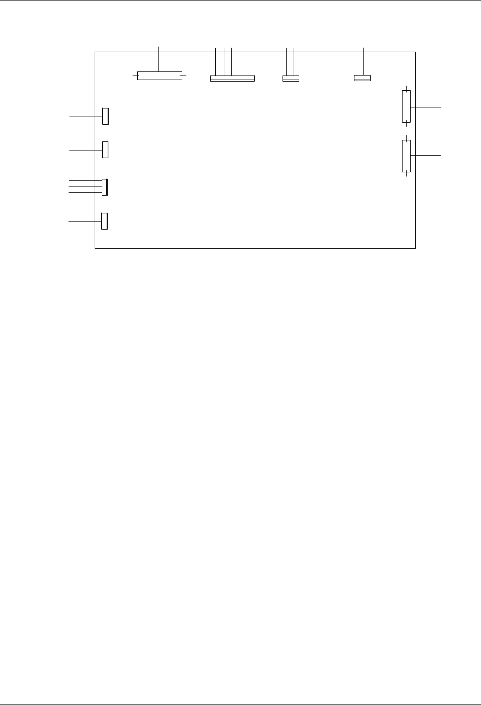
26 Chapter 3 Electrical Installation
HIPULSE U UPS Single Module And “1+N” (Expandable) 160/200/300/400kVA User Manual
W303-2
W300-3
W300-2
W98-13
W98-12
W41-5
W45-5
W45-4
I1-J9
W302
W302
W303-1
W302
W301
W300-1
T20
T19
J6
I1-J9
J5
F1/F2/F3
J7
I1-J1
J12
J11
FAN15
FAN14
FAN13 J3
A5(1)-J5
J4
A5(1)-J3
J2
FAN12
J1
I1-J13/J14
W58
J10
A2(1)-X7
A2(2)-X7
ULW36CSA8
Figure 3-12 Signal cable connection between main cabinet and side cabinet of 400kVA UPS
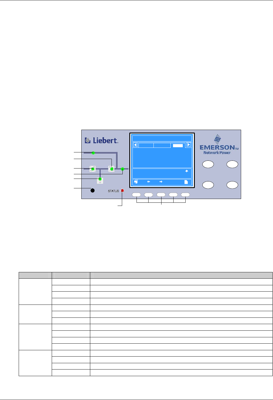
Chapter 4 Operator Control And Display Panel 27
HIPULSE U UPS Single Module And “1+N” (Expandable) 160/200/300/400kVA User Manual
Chapter 4 Operator Control And Display Panel
This chapter expounds the functions and use of the components on the operator control and display panel of the
HIPULSE U UPS, and provides LCD display information, including the LCD screen types, detailed menu messages,
prompt windows and UPS alarm message list
4.1 Introduction
The operator control and display panel is located on the front door of the UPS. The panel is the access point for
operator control and monitoring of all measured parameters, UPS and battery status and of event and alarm logs.
The operator control and display panel is divided into three functional areas: mimic power flow chart, graphic LCD
monitor with menu keys, control buttons, as shown in Figure 4-1.
INVERTER
ON
FAULT
CLEAR
F2 F4 HEL PF1 F3
INVERTER
OFF
SILENCE
ON/OFF
12:30:36
Unit #1 Normal
?
Bypass
Main
Vphase V
Iphase A
Freq. Hz
Vline V
P. F.
A(AB)
220
20.5
50.1
380
0.99
B(BC)
220
20.5
50.1
380
0.99
C(CA)
220
20.5
50.1
380
0.99
Output
Input Breaker Closed 10-12 12:28:16
Manual Turn On 10-12 12:30:06
UPS in Normal Mode 10-22 12:30:16
200kVA-3X3
HIPULSE U 2006-01-01
Mimic power flow chart Control buttons
Battery LED
Buzzer
Graphic LCD monitor
with menu keys
Rectifier LED
Bypass LED
Inverter LED
Load LED
Alarm LED LCD menu keys
Figure 4-1 Operator control and display panel
4.1.1 LED Indicators
The six LEDs mounted on the mimic flow chart represent the various power paths of the UPS, and indicate the
current UPS operational status and alarm status by color (red, green, yellow) and state (ON, OFF, flashing), as
described in Table 4-1.
Table 4-1 Description of LED indicators
LED State Description
Steady green Rectifier in normal operation
Flashing green Input AC normal, but rectifier not operating
Steady red Rectifier f failed
Rectifier LED
OFF Rectifier not operating, input ac not available or out of normal range
Steady green Load on bypass power
Steady red Bypass not available, out of normal range or static bypass switch fault
Bypass LED
OFF Bypass normal, load not on bypass power
Steady green Battery normal, but discharging and powering the load
Flashing green Battery end-of-discharge pre-warning
Steady red Battery abnormal (failed, absent or polarity reversed) or battery circuit breaker abnormal
Battery LED
OFF Battery and battery circuit breaker normal, battery charging
Steady green Inverter normal and powering the load
Flashing green Inverter ON, starting up, synchronizing, or standing by (ECO mode)
Steady red Inverter failed
Inverter LED
OFF Inverter not operating
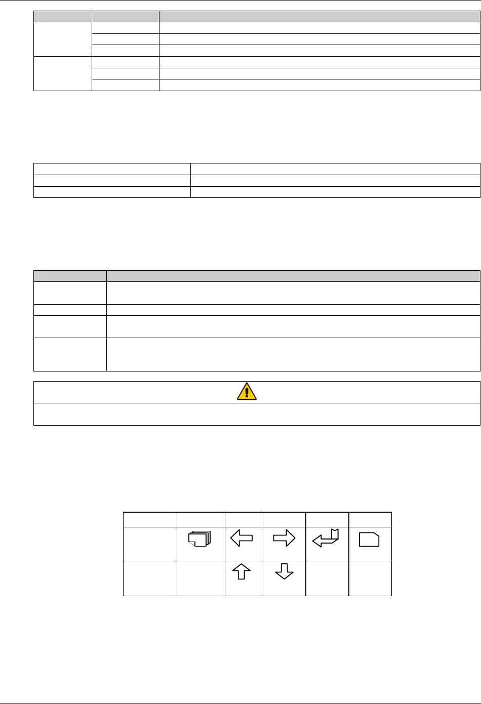
28 Chapter 4 Operator Control And Display Panel
HIPULSE U UPS Single Module And “1+N” (Expandable) 160/200/300/400kVA User Manual
LED State Description
Steady green UPS output ON and normal
Steady red UPS output ON and overloaded
Load LED
OFF UPS output OFF
Steady green Normal operation
Steady yellow UPS warning (for example, AC input failure)
Alarm LED
(STATUS) Steady red UPS fault (for example, fuse or hardware failure)
4.1.2 Buzzer
The operator control and display panel provides a buzzer. UPS activity is accompanied by the following sounds.
Table 4-2 Audible alarm description
Single beep Direct access key acknowledgement
One beep per second UPS warning. For example, AC input failure
Continuous beep Fault. For example, fuse or hardware failure
4.1.3 Control Buttons
The operator control and display panel provides four control buttons, as described in Table 4-3.
Table 4-3 Description of control buttons
Control button Description
INVERTER ON Pushing this button turns on the inverter.
Note: If the inverter is not ready, pushing this button cannot turn on the UPS
INVERTER OFF During UPS operation, pushing this button turns off the inverter and transfers the load to the bypass
FAULT CLEAR In case the UPS shuts down due to fault, after eliminating the alarm conditions, pushing this button clears
the fault
SILENCE
ON/OFF
When an alarm is active, pushing this button silences the audible alarm. When a new alarm occurs
afterwards, the buzzer will give audible alarm again. When there is no audible alarm, pushing this button
initiates the audible alrm test
Note
To activate the above control buttons, you are required to press and hold the buttons for approximately 2 seconds until a beeping
sound is heard.
4.1.4 LCD And Menu Keys
The operator control and display panel provides an LCD and five menu keys (F1, F2, F3, F4, HELP). The menu keys
are described in Table 4-4.
Table 4-4 Menu key icons and their meaning
Key F1F2F3F4
ESC
?
Shift
Escape
Left
Up
Right
Down
Enter Help
HELP
Function 1
Function 2
The user-friendly and menu-driven LCD allows you to easily browse through the input, output, load and battery
parameters, learn current UPS status and alarm information, perform functional setting and control operation. The
LCD also stores up to 512 historical records that can retrieve for reference and diagnosis.
As shown in Figure 4-2, the LCD primary screen is divided into five windows: system information window, menu
window, UPS data window, and current record window. Pressing the F1 key scrolls through the user-operable
windows.
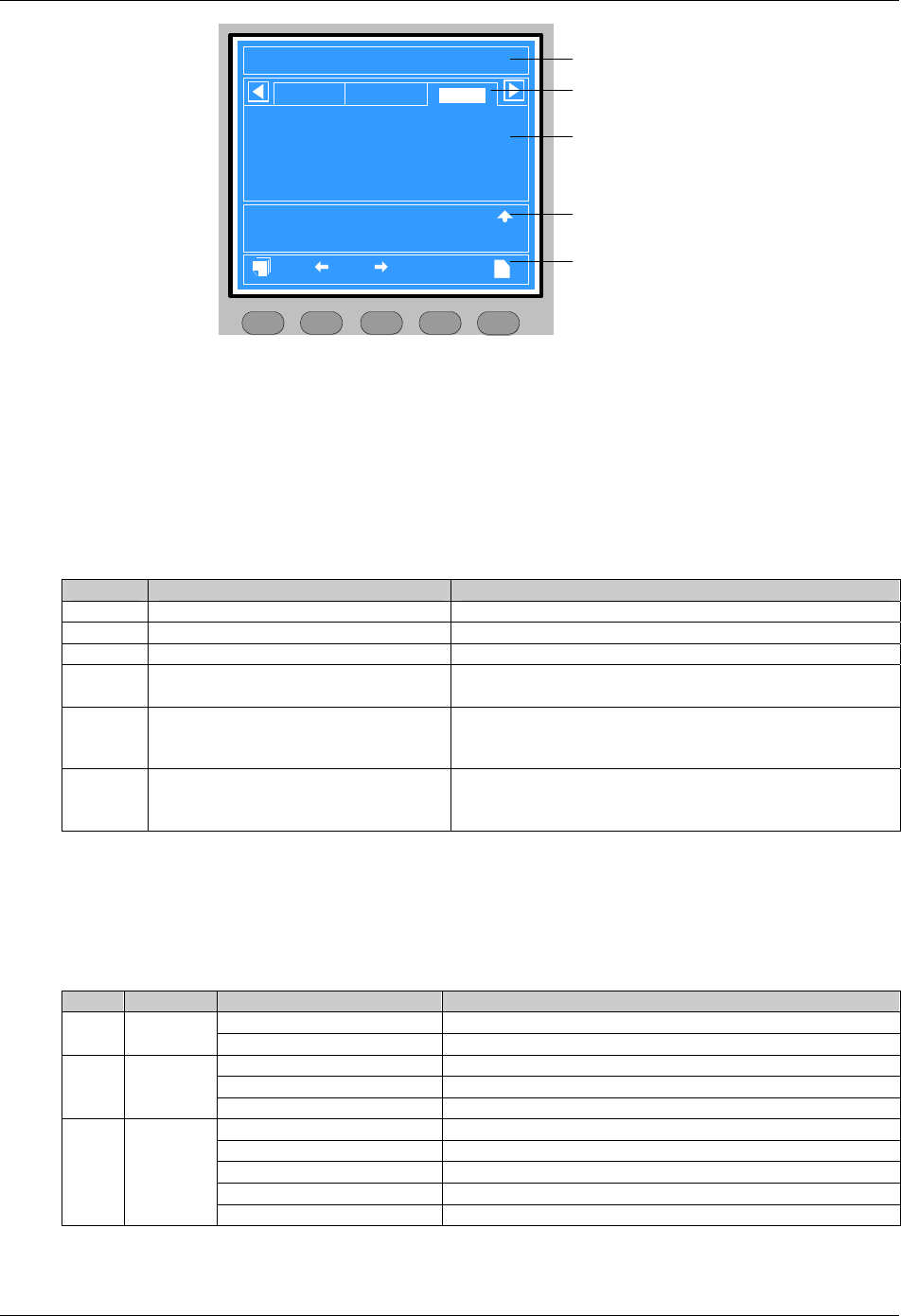
Chapter 4 Operator Control And Display Panel 29
HIPULSE U UPS Single Module And “1+N” (Expandable) 160/200/300/400kVA User Manual
HIPULSE U 2006-01-01 12:30:36
200kVA-3X3 Unit #1 Normal
?
Bypass
Main
Vphase V
Iphase A
Freq. Hz
Vline V
P. F.
A(AB)
220
20.5
50.1
380
0.99
B(BC)
220
20.5
50.1
380
0.99
C(CA)
220
20.5
50.1
380
0.99
Output
Input breaker closed 10-12 12:28:16
Manual turn on 10-12 12:30:06
UPS in normal mode 10-22 12:30:16
UPS System Window
UPS Menu Window
UPS Data Window
Current Record Window
Keypad Window
F2 F4 HELPF1 F3
Figure 4-2 LCD primary screen
4.1.5 Detailed Description Of Menu Items
The description that follows refers to the LCD primary screen shown on Figure 4-2.
System information window
The system information window displays current time and date and identifies the UPS, its configuration and its status.
For details, see Table 4-5.
Table 4-5 System information window
No. Item Explanation
1 HIPULSE U UPS family name
2 2006-01-01 Current date
3 12:30:36 Current time
4 200kVA-3x3 200kVA: UPS rated output
3 x 3: 3-phase input and output
5 (Configuration) Single, ECO, or Unit # 1
Single: single unit
ECO: single unit operating in ECO mode
Unit # 1: of max 6 units in a parallel system
6 (Status) Normal, Warning, or Fault
Normal: UPS in normal operation, load on inverter, no alarm
Warning: system attention required
Fault: serious UPS fault existing
Menu window and UPS data window
The menu window provides the menus of the STS data window. The UPS data window displays the items of the
menu selected in the menu window. UPS parameters can be browsed and functions can be set through the menu
window and UPS data window. Details are provided in Table 4-6.
Table 4-6 Menu window and UPS data window
No. Menu Item Explanation
L-L voltage (V) Line voltage
1 Mains
Frequency (Hz) Input frequency
L-N voltage (V) Phase voltage
Frequency (Hz) Bypass frequency
2 Bypass
L-L voltage (V) Line voltage
L-N voltage (V) Phase voltage
L-N current (A) Phase current
Frequency (Hz) Output frequency
L-L voltage (V) Line voltage
3 Output
Power factor Power factor

30 Chapter 4 Operator Control And Display Panel
HIPULSE U UPS Single Module And “1+N” (Expandable) 160/200/300/400kVA User Manual
No. Menu Item Explanation
Sout (kVA) Apparent power
Pout (kW) Active power
Qout (kVAR) Reactive power
Loadlevel (%) The percentage of the UPS rating load
4 Load
Crest factor Output current crest factor
Sout (kVA) Apparent power
Pout (kW) Active power
Qout (kVAR) Reactive power
5 System
Single system, no parallel data When configured as a single unit, UPS has only native load, no
system load
Battery voltage (V) Battery bus voltage
Battery current (A) Battery bus current
Battery temperature (°C) Internal battery temperature °C
Battery remain time (Min.) Battery run time remaining
Battery boost charging Battery is boost charging
Battery float charging Battery is float charging
6 Battery
Battery is not connected Battery is not connected
7 Records
……
Inverter output abnormal
20-01-2006 11:30:02
22-01-2006 13:38:06
Battery maintained
22-01-2006 13:38:02
22-01-2006 13:38:36
……
Displays up to 512-event history log indicating system status with
start/stop date and time stamp for each event.
You may scroll through the history log.
Refer to Table 4-8 for a complete list of UPS alarm messages
8 Language
中文/English
Selects display in Chinese or English.
Use F1, up and down arrow keys (F2, F3) to select this menu item,
and press the Enter key (F4).
Use left and right arrow keys (F2, F3) to reach desired language and
press the Enter key (F4)
Display contrast
Adjusts the graphic LCD monitor contrast for best viewing.
Use the Shift key (F1) and up and down arrow keys (F2, F3) to
highligt this setting. Press the Enter key (F4).
Select setting with left and right arrows (F2, F3) and press the Enter
key (F4)
Date format set
YYYY MM DD, DD MM YYYY and MM DD YYYY formats can be
selected.
Use the Shift key (F1) and up and down arrow keys (F2, F3) to
highligt this setting. Press the Enter key (F4).
Select setting with left and right arrows (F2, F3) and press the Enter
key (F4)
Date & time
Adjusts time (in 24-hr format) and Date format (in user defined format
previously set).
Use the Shift key (F1) and up and down arrow keys (F2, F3) to
highligt this setting. Press the Enter key (F4).
Enter each date or time digit with up arrow (F2) and use right arrow
(F3) to access next field. Press the Enter key (F4) when all digits
have been entered
9 Settings
Comm1 baud rate
(Monitoring board RS232-1,
Intellislot 2)
Comm2 baud rate
(Monitoring board RS232-2,
Intellislot 1)
Comm3 baud rate
(Monitoring board Intellislot 3)
Adjusts the transmission speed of any of the 3 UPS communication
ports available. Available settings are
- 9600bps (default setting, SNMP card supports this baud rate only)
- 4800bps
- 2400bps
Use the Shift key (F1) and up and down arrow keys (F2, F3) to
highligt the desired port and baud rate. Press the Enter key (F4)

Chapter 4 Operator Control And Display Panel 31
HIPULSE U UPS Single Module And “1+N” (Expandable) 160/200/300/400kVA User Manual
No. Menu Item Explanation
Communication address
This setting applies to RS485 communication and the
“one-to-multiple points” communication mode of parallel system. It is
required to set the parameter Host communication mode of COM1 in
parallel system to Multipoint to point using background software
before setting the communication address of each UPS module
Communication mode Reserved modem function. No need to change the default setting
“RS232”
Callback times (reserved)
Phone No.1 (reserved)
Phone No.2 (reserved)
Phone No.3 (reserved)
9 Settings
Command password
Modifies password for the Command menu.
Use the Shift key (F1) to highligt Command Password, press the
Enter key (F4).
Enter each old password digit with up arrow (F2) and use right arrow
(F3) to access next field. Press the Enter key (F4) when all digits
have been entered.
Follow prompts and repeat the process for new password
Battery maintenance test
Manually initiates battery maintenance test, which will lead to the
battery being partly discharged, for rough assessment of the battery
capacity.
The Load must exceed 20% and be less than 80% of rated UPS
capacity, and the battery must have been float charging for 5 hours or
more.
Use the Shift key (F1) and up and down arrow keys (F2, F3) to
highligt the desired test. Press the Enter key (F4).
Enter each password digit with up arrow (F2) and use right arrow (F3)
to access next field. Press the Enter key (F4) when all digits have
been entered
Battery capacity test
Manually initiates battery capacity test, which will lead to the battery
being completely discharged, for accurate assessment of the battery
capacity.
The Load must exceed 20% and be less than 80% of rated UPS
capacity, and the battery must have been float charging for 5 hours or
more.
Use the Shift key (F1) and up and down arrow keys (F2, F3) to
highligt the desired test. Press the Enter key (F4).
Enter each password digit with up arrow (F2) and use right arrow (F3)
to access next field. Press the Enter key (F4) when all digits have
been entered
System test
Manually initiates the system test.
The user actives this function, after 5 seconds, a pop window will
appear to show the result of this diagnosis: Rectifier, Inverter, Monitor
OK or Fault
Stop testing Manually stop the test, including maintenance test, capacity test and
system test
Freshening charge
Manually initiates freshening charge, when the battery is not in boost
charge state.
Use the Shift key (F1) and up and down arrow keys (F2, F3) to
highlight this item. Press the Enter key (F4).
Enter each password digit with up arrow (F2) and use right arrow (F3)
to access next field. Press the Enter key (F4) when all digits have
been entered
10 Command*
Stop freshening charge Manually stop the freshening charge
Monitor Version:Vxxx
Rectifier Version:Vxxx
Inverter Version:Vxxx
Displays UPS firmware versions, including inverter, rectifier,
monitoring board firmware versions
11 Version
UPS model Displays UPS model information; for example, 380V-50Hz
Note*: password controlled. The default passward is “12345”, please enter Settings=>Command password to change the
password. In case the password is lost, please contact the local customer service center of Emerson
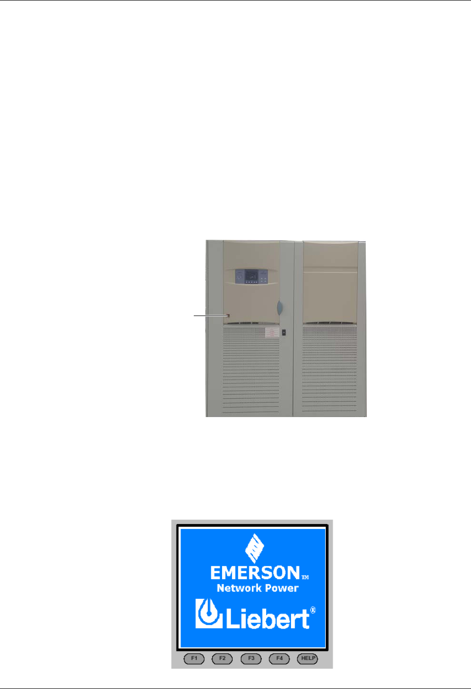
32 Chapter 4 Operator Control And Display Panel
HIPULSE U UPS Single Module And “1+N” (Expandable) 160/200/300/400kVA User Manual
Current record window
Keeps a log of current alarms, ignores transient conditions that have been resolved. Use F1, F2 and F3 to read the
alarm messages.
For a complete history log, refer to the Records menu in Table 4-6.
Refer to Table 4-8 for a complete list of UPS alarm messages.
Keypad window
The function of menu keys F1 to F4 and HELP is shown by a self-explanatory icon as appropriate for the particular
window.
4.1.6 EPO Button
As shown in Figure 4-3, the UPS door provides an emergency power off (EPO) button. It is housed beneath a safety
cover to prevent inadvertent operation. After the EPO button has been pressed and hold for 2 seconds, it disables the
static switch block entirely (so removing load power). It also disables the rectifier and inverter, and trips the battery
circuit breaker. Under normal circumstances it does not remove UPS input power since this is applied through a
manually controlled external isolator; however, if the UPS input supply is connected through circuit breaker having an
electrical trip facility, the EPO switch can be used to drive the external circuit breaker’s trip circuit so as to remove the
UPS input power.
Emergency
power off (EPO)
button
Figure 4-3 Emergency power off button
4.2 LCD Screen Types
4.2.1 Start Screen
Upon UPS start, the UPS executes system test, and the start screen will appear and remains approximately 15
seconds, as shown in Figure 4-4.
Figure 4-4 Start screen
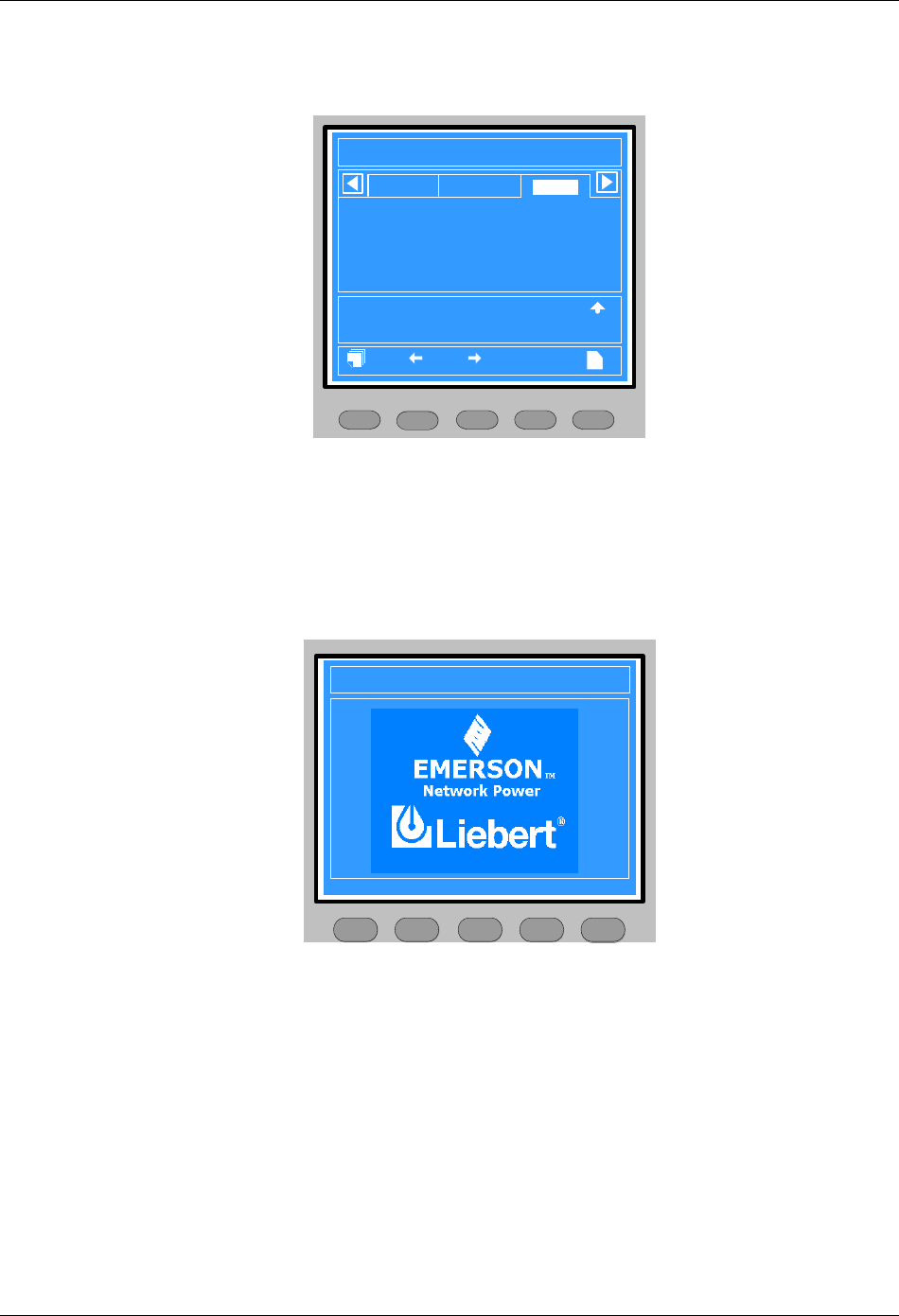
Chapter 4 Operator Control And Display Panel 33
HIPULSE U UPS Single Module And “1+N” (Expandable) 160/200/300/400kVA User Manual
4.2.2 Primary Screen
After the UPS starts and finishes system test, the primary screen will appear, as shown in Figure 4-5. For details
about the primary screen, refer to 4.1.5 Detailed Description Of Menu Items.
F2 F4 HELPF1 F3
12:30:36
Unit #1 Normal
?
Bypass
Main
Vphase V
Iphase A
Freq. Hz
Vline V
P. F.
A(AB)
220
20.5
50.1
380
0.99
B(BC)
220
20.5
50.1
380
0.99
C(CA)
220
20.5
50.1
380
0.99
Output
Input Breaker Closed 10-12 12:28:16
Manual Turn On 10-12 12:30:06
UPS in Normal Mode 10-22 12:30:16
200kVA-3X3
HIPULSE U 2006-01-01
Figure 4-5 Primary screen
4.2.3 Default Screen
During UPS operation, if there is neither an alarm nor a keypad operation within two minutes, the default screen will
appear, as shown in Figure 4-6. Two minutes later, the LCD backlight will turn off. When an alarm occurs or a key is
pressed, the primary screen will return, and the LCD backlight will turn on.
The LCD will also return to the primary screen when pressing any menu key at the default screen.
HIPULSE U 2006-01-01 12:30:36
200kVA-3X3 Unit #1 Normal
Press any key, back to main menu.
F2 F4 HELPF1 F3
Figure 4-6 Default screen
4.2.4 Help Screen
At the primary screen, use the HELP key to display the help screen, as shown in Figure 4-7. This screen describes
current meanings of the menu keys to help you with the menu operation. Pressing the HELP key exits the help
screen and returns to the primary screen.
34 Chapter 4 Operator Control And Display Panel
HIPULSE U UPS Single Module And “1+N” (Expandable) 160/200/300/400kVA User Manual
F2 F4 HELPF1 F3
?
Q3
Q2
Q1 Q5
Help information
Select the previous menu item
Select the current record window
Select the next menu item
Figure 4-7 Help screen
Operation of the HELP key:
1. Only at the primary screen can you use the HELP key to display the help screen.
2. The HELP key is invalid at the start screen.
3. At the default screen, help screen, or when the LCD backlight is off, the primary screen will return if you press the
HELP key.
4.3 Prompt Window
A prompt window is displayed during the operation of the system to alert you to certain conditions and/or to require
your confirmation of a command. The prompts are provided in Table 4-7.
Table 4-7 Prompts and meanings
No. Prompt Meaning
1 Transfer with interrupt, confirm or
cancel
Inverter and Bypass supplies are not synchronized and any load transfer
between the supplies will cause a brief load interruption
2 The load is too high to be
transferred with interrupt
The total load must be less than the capacity of one unit to allow a parallel
system to perform an interrupted transfer from bypass to inverter
3 This operation leads to output
shutdown, confirm or cancel
No alternative supply is available and any Inverter Off operation will cause the
load to be de-energised
4 This operation leads to inverter
overload, confirm or cancel
Turning off this inverter will lead to the overload of remaining inverter(s) in a
parallel system
5 Turn on more UPS to carry current
load
The number of paralleled inverters already turned on is insufficient to carry the
existing load
6 Battery will be depleted, confirm or
cancel
Battery capacity test discharges the battery 100%. This prompt apears to
require your confirmation. Cancelling the test will ends the test and transfers the
UPS to Normal mode
7 System selftest finished, everything
is ok No action required
8 System selftest finished, please
check the current warnings Check the current record window
9 Enter control password Required for battery or UPS test (default: 12345)
10
Battery selftest condition is low,
please check battery state and
loadlevel
Battery test condition is not met. Please check whether the battery is in boost
charge state and the load level meet the battery test conditions. To initiate the
battery test, the load must range between 20% and 80%
11
Freshening charge condition is low,
please check battery settings and
state
This prompt appears when you select the freshening charge command while
the freshening charge condition is not met (such as no battery, charger failure)

Chapter 4 Operator Control And Display Panel 35
HIPULSE U UPS Single Module And “1+N” (Expandable) 160/200/300/400kVA User Manual
4.4 UPS Alarm Message List
Table 4-8 provides the complete list of UPS alarm messages supported for display either on the Records menu
(historical data) or in the current record window (prevailing data) as described in 4.1.5 Detailed Description Of Menu
Items.
Table 4-8 UPS alarm message list
Alarm message Description
Rectifier comm. fail Internal RS485 communication failure between monitor and rectifier
Mains volt. abnormal Mains Voltage exceeds the upper or lower limit and results in rectifier shutdown. Check the input
line-to-neutral voltage amplitude of rectifier
Mains undervoltage Mains voltage is undervoltage. Check the input line voltage
Mains freq. abnormal Mains frequency is out of limit range and results in rectifier shutdown. Check the input voltage and
frequency
Battery fuse fail Battery fuse flowout led to BCB tripping
Rectifier block Rectifier detected faulty. Rectifier shuts down. Battery discharges
Rectifier overtemp. The temperature of heat sink is too high to keep the rectifier running. The UPS can recover
automatically. Check the environment and ventilation
Input fuse fail Input fuse blowout led to rectifier turning off
Control power 1 fail UPS operates but Control Power is not available
Control power 2 fail UPS operates but Redundant Control Power is not available
Mains phase reversed Rectifier AC input phase sequence is reversed
Rectifier current limit Rectifier overcurrent led to power limiting operating
Soft start fail Rectifier could not start due to low DC bus voltage
Input filter fault Filter inductor overtemperature led to filter contactor tripping
Filter contactor fault Filter contactor operation abnormal
Filter overcurrent Mains power outside the normal voltage or frequency range of the input passive filter results in filter
overcurrent. Please find out the reason for the mains power abnormality
REC drive cirtuit fault Rectifier being off due to improper connection of rectifier drive cable or rectifier type setting error
REC input Ph. missing Rectifier input phase missing. Check the input power connection or if the mains power is abnormal
DC bus over voltage Rectifier and inverter were shut down because DC bus voltage is too high. Check whether there is a
fault in rectifier side
Bus capacitor overvolt Bus capacitor voltage exceeds 350V, rectifier is off. Check the voltages of the two groups of bus
capacitors
EPO Emergency Power Off direct access key pressed or external command received
Input disconnect open Rectifier input switch open
Input disconnect closed Rectifier input switch closed
Normal mode Load supplied from inverter output through double conversion of the AC mains input supply
Source share mode Load supplied from inverter output through shared double conversion of the AC mains input supply
and of the Battery supply
PPF online Reactive input filter connected
PPF disconnecting Reactive input filter disconnected
Battery mode Load supplied from inverter output through battery
No battery Check the battery and the battery wiring; check whether the BCB is closed and the BCB dry contact
is connected
Auto start After UPS was shutdown at EOD, inverter auto starts when utility restore
Generator connected The generator has been connected to the UPS
BCB open Battery Circuit Breaker status (open)
BCB closed Battery Circuit Breaker status (closed)
Battery float charging Battery status (Float charge mode)
Battery boost charging Battery status (Boost charge mode)
Battery discharging Battery status (discharge mode)
Battery period testing Automatic periodic battery maintenance discharge test (20% capacity discharge)
Batt. capacity testing User initiated battery capacity discharge test (100% capacity discharge)
Batt. maint. testing User initiated maintenance discharge test (20% capacity discharge)
UPS system testing User initiated system test
Inverter in setting Inverter starting up and synchronizing
Rectifier in setting Rectifier starting up and synchronizing
Battery Room Alarm Environment in Battery Room Needs Attention

36 Chapter 4 Operator Control And Display Panel
HIPULSE U UPS Single Module And “1+N” (Expandable) 160/200/300/400kVA User Manual
Alarm message Description
REC FLASH UPDATE Ongoing update of rectifier firmware
INV FLASH UPDATE Ongoing update of inverter firmware
MONITOR FLASH
UPDATE Ongoing update of monitor firmware
Unit off confirm Prompt to press the Enter key (F4) to acknowledge that the UPS will be disconnected from other
paralleled UPS modules
System off confirm Prompt to press the Enter key (F4) to acknowledge that the all paralleled UPS will be disconnected
from the load
Fault reset FAULT CLEAR direct access key pressed
Alarm silence SILENCE ON/OFF direct access key pressed
Turn on fail Inverter failed to turn on when INVERTER ON direct access key was pressed. This may be as a
result of Invalid Operation (Maintenance bypass on) or DC bus or rectifier not ready
Alarm reset FAULT CLEAR or SILENCE ON/OFF direct access key pressed
Transfer confirm Prompt to press the Enter key (F4) to acknowledge that an interrupted load transfer to bypass will
happen
Transfer cancel Prompt to press the ESC key (F4) to avoid that an interrupted load transfer to bypass will happen
Manual turn on Manual Turn On through operator control and display panel
Manual turn off Manual Turn Off through operator control and display panel
Battery ground fault Battery leakage to ground detected (option)
Protocol version clash Firmware incompatibility between Monitor Board and Digital Signal Processor Board
Setting save error History records not saved. (Reserved)
Battery overtemp. The Battery temperature is over limit. Check the battery temperature and ventilation
Ambient overtemp. The Ambient temperature is over limit. Check the ventilation of UPS room
Battery fault Battery detected faulty (Reserved)
Battery maintained Battery test failed, Battery should be replaced
Battery low pre-warning
Before the end of discharge, battery undervoltage pre-warning should occur. After this pre-warning,
battery should have the capacity for 3 minutes discharging with full load. The time is user-configured
from 3 to 60 minutes. Shut down the load in time
Battery end of discharge Inverter turned off due to low battery voltage. Check the utility failure and try to recover it
Inverter comm. fail Internal RS485 communication failure between monitor and inverter
Parallel comm. fail
The CAN communication between different UPSs within a parallel system fails. 1.Check if there are
some UPSs not powered on in the parallel system. If so, power on these UPSs and check if the
alarm disappears. 2. Press the FAULT CLEAR push button
Bypass unable to trace
This alarm is triggered by an inverter software routine when the amplitude or frequency of bypass
voltage is beyond the normal range. The amplitude threshold is fixed for positive and negative 10%
rating.
This alarm automatically resets once the bypass voltage goes normal. 1. First verify that the bypass
voltage and frequency displayed on the operator control and display panel is within the selected
range. Note here the rated voltage and frequency are specified by the system voltage level and
output frequency level respectively. 2. If the displayed voltage is believed to be abnormal, then verify
the bypass voltage and frequency presented to the UPS. Check the external supply if it is found to
be faulty
Bypass abnormal
This alarm is triggered by an inverter software routine when the amplitude or frequency of bypass
voltage exceeds the limit. This alarm automatically resets once the bypass voltage goes normal.
First check if there are some relevant alarms such as Bypass disconnect open, Bypass phase
reverse. If they appear, solve them first. 1. Then verify that the bypass voltage and frequency
displayed on the operator control and display panel is within the bypass limit. Note here the rated
voltage and frequency are specified by the system voltage level and output frequency level
respectively. 2. If the displayed voltage is believed to be abnormal, then verify the bypass voltage
and frequency presented to the UPS. Check the external bypass supply if it is found to be faulty. If
the utility is likely to trigger this alarm frequently, the bypass limit can be changed a little larger
through the configuration software according to the customer’s agreement
Inverter asynchronous
This alarm is triggered by an inverter software routine when the inverter and bypass waveforms are
misaligned by more than 6 degrees in phase. This alarm resets automatically once the condition is
no longer true. 1. First check if the alarm Bypass unable to trace or Bypass abnormal occurs. If so,
solve it first.
2. Verify the waveform of the bypass voltage. If it is too distorted, ask the customer to verify and seek
any possible measurements
Inverter output abnormal Inverter output voltage beyond limits. Load transfers to bypass

Chapter 4 Operator Control And Display Panel 37
HIPULSE U UPS Single Module And “1+N” (Expandable) 160/200/300/400kVA User Manual
Alarm message Description
Inverter overtemp.
The temperature of the inverter heat sink is too high to keep inverter running. This alarm is triggered
by the signal from a temperature monitoring thermostat on the inverter bridge heat sink. The UPS will
recover automatically after a 5 minute delay from the disappearance of the overtemperature signal. If
the overtemperature condition is true, then check for and verify: 1. high ambient air temperature. 2.
blocked cooling airway. 3. any fan failure. 4. prolonged inverter overload
Fan fault At least one of the cooling fans has failed
Inverter STS fail At least one of the static switches of inverter side is open or short circuit. This fault is locked until
power off
Bypass STS fail At least one of the static switches of bypass side is open or short circuit. This fault is locked until
power off
Operation invalid This record is registered following an incorrect operation
Unit over load
The UPS is confirmed to be overload when the load arises above 105% nominal rating. The alarm
automatically resets once the overload condition is removed. 1. Confirm that the alarm is true by
checking the load percent indicated on the LCD to determine which phase is being overloaded. 2. If
the alarm is true, measure the actual output current to verify that the indications are valid.
Disconnect unnecessary load and ensure the safety. In a parallel system, a severe load sharing error
can also leads to the alarm
System over load
The UPS parallel system is confirmed to overload when the total load arises above 105% nominal
rating for the set basic number of UPSs. The alarm automatically resets once the overload condition
is removed.
1. Confirm that the alarm is true by checking the system load percent indicated on the LCD to
determine which phase is being overloaded. 2. If the alarm is true, measure the actual output current
to verify that the indications are valid.
Disconnect unnecessary load and ensure the safety. In a parallel system, a severe load sharing error
can also leads to the alarm
Unit over load timeout
The UPS is confirmed to overload and the overload times out.
Note 1: the highest loaded phase will indicate overload timing-out first. Note 2: When the timer is
active then alarm “unit overload” should also be active as the load is above nominal.
Note 3: When the timer has expired, the inverter Static Switch is opened and the load transferred to
bypass. The inverter shutdown and will restart after 10 seconds. Note 4: If the load decreases lower
than 95% after 5 minutes, the system will transfer back to inverter mode.
Confirm that the alarm is genuine by checking the load percent indicated on the LCD. If an overload
is indicated then check the load, and investigate any additional load connected prior to the alarm (if
applicable)
Byp. abnormal shutdown Both bypass and inverter voltages unavailable. Load interruption
Inverter over current Inverter pulse width modulation module overloaded
Bypass phase reverse
The phase sequence direction of bypass voltage is reversed. Normally, the phase of phase B lags
120 degrees behind phase A, and the phase of phase C lags 120 degrees behind phase B.
Verify that the phase rotation of the bypass supply presented to the UPS is correct, and rectify it if it
is found to be in error
Load impact transfer A transfer to bypass occurred due to a large step load. The UPS should recover automatically. Turn
on connected equipment in sequential order to reduce the step loading of the inverter
Transfer time-out The load is on bypass power due to excessive number of transfers that occurred within the last hour.
The UPS will recover automatically and will transfer the load back to inverter power within an hour
Load sharing fault UPS modules within a parallel system are not sharing the load current equally
DC bus abnormal DC input voltage to inverter beyond limits. Inverter shuts down. Load transfers to bypass
System transfer The whole paralleled UPS system transferred to bypass at the same time. This message will appear
on the UPS which passive transfer to bypass
Parallel board fault Malfunction of the paralleling control circuits of this UPS module. Can cause system transfer to
bypass
Parallel connect fault
The parallel cables are not connected correctly in a parallel system.
Reset the fault by pressing the FAULT CLEAR button, then restart the inverter by pressing the
INVERTER ON button
Bypass over current Bypass current is over limit above 135% rating. The UPS just alarms and does nothing
LBS Active Load Bus Synchronization is active. The UPS is acting as an LBS master or slave in a dual bus
configuration
LBS abnormal UPS set to LBS mode (master or slave), but no LBS signal on LBS bus. Check the LBS bus
connection
Byp. induct overtemp. Bypass load sharing inductor overtemperature. Check the environment and ventilation
Static Sw. overtemp. Overtemperature of static switch on bypass or inverter side. Check the environment and ventilation

38 Chapter 4 Operator Control And Display Panel
HIPULSE U UPS Single Module And “1+N” (Expandable) 160/200/300/400kVA User Manual
Alarm message Description
Byp. feedback fault
UPS feeds output voltage back to the mains grill through bypass due to shortcircuit of static switch
on bypass side during mains failure. In this case, lack of protective bypass switch or improper
connection of switch auxiliary contact will endanger the user safety. Special attention should be paid
to this
INV drive circuit fault Improper connection of inverter drive cable, or equipment type setting error
Bypass disconnect
closed Bypass switch closed
Bypass disconnect open Bypass switch open
Maint. disconnect closed Maintenance bypass switch closed
Maint. disconnect open Maintenance bypass switch open
Output disconnect closed Output switch closed
Output disconnect open Output switch open
Check UPS output The UPS is off and has no output
Output disabled
If the UPS auto-recovery after EOD function is disabled, after UPS shutdown due to battery
discharge to EOD (end-of-discharge) voltage, when the mains power is restored, the UPS will not
restart automatically, and the LCD will display this alarm message
Normal mode The UPS is in Normal mode
Battery mode The UPS is in Battery mode
Source share mode The UPS is in Source Share mode
Bypass mode The UPS is in Bypass mode
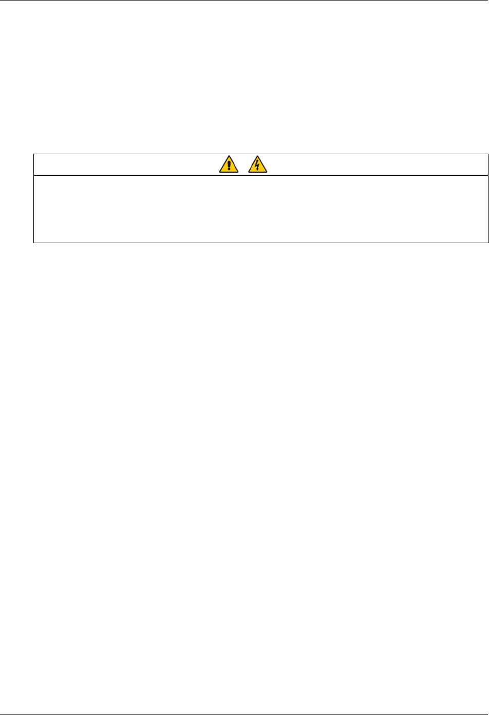
Chapter 5 Operating Instructions 39
HIPULSE U UPS Single Module And “1+N” (Expandable) 160/200/300/400kVA User Manual
Chapter 5 Operating Instructions
This chapter provides detailed operating notes and instructions of the HIPULSE U UPS.
5.1 Introduction
5.1.1 Notes
Important
Only after an authorized engineer has conducted the initial power-on and finished the UPS configuration is the user allowed to
operate the UPS.
No user accessable parts are located behind covers that require a tool for their removal. Only qualified service personnel are
authorised to remove such covers.
Hazardous voltages are always present at the UPS input and output terminals. If the UPS is fitted with an internal Class A filter,
the filter carries hazardous voltages too.
1. All the user controls and indicators (LED) mentioned in these procedures are identified in Chapter 4 Operator
Control And Display Panel.
2. The audible alarm may annunciate at various points in these procedures. It can be canceled at any time by
pressing the SILENCE ON/OFF button.
3. The HIPULSE U UPS system incorporates an optional automatic boost charge facility, which can be used in
systems containing conventional flooded lead-acid batteries. If this type of battery is used in your installation you may
notice that the battery charger voltage may be greater than its nominal (432Vdc for 380Vac, 446Vdc for 400Vac and
459Vdc for a 415Vac system) when the mains supply returns from a prolonged outage. This is the normal response of
the boost charge facility: the charger voltage should return to normal after a few hours.
5.1.2 Power Switches
The UPS can be separated by means of power switches, mounted inside the cabinet and accessible after opening
the front door, which has a key. The location of the UPS power switches is shown in Figure 5-1 and Figure 5-2.
The UPS module power switches are:
Q1 — input switch: Connects the UPS with the mains supply.
Q2 — bypass switch: Connects the UPS with the bypass supply.
Q3 — maintenance bypass switch (padlocked): Permits supply of the load directly by the bypass line for maintenance
of the UPS module.
The internal maintenance bypass must not be used when the UPS system is comprised of more than two UPS
modules in parallel.
Q5 — output switch: Connects the output of the UPS to the load.
Note: The battery circuit breaker (BCB) is not expected inside of the UPS and should be installed in the proximity of
the respective battery.
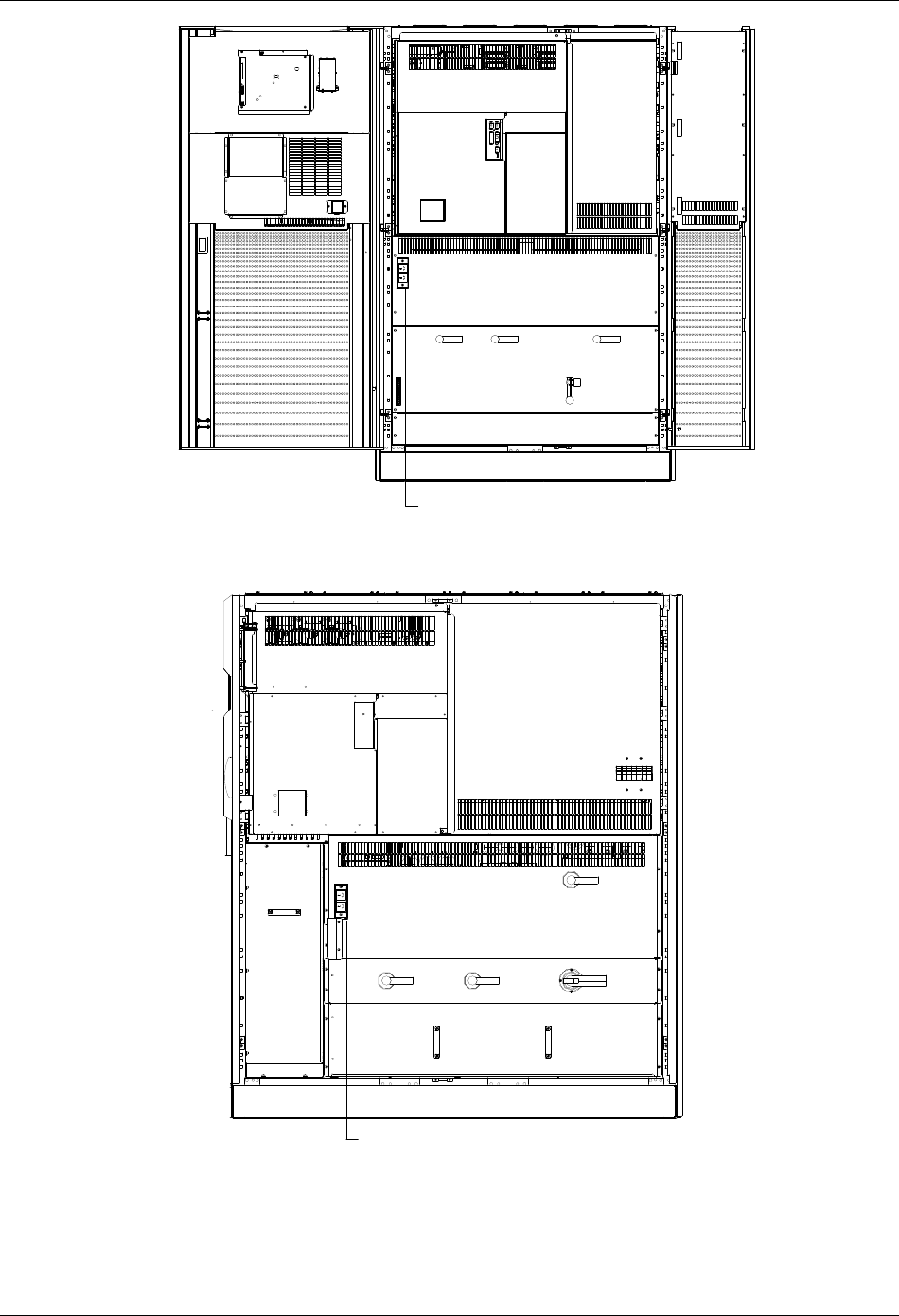
40 Chapter 5 Operating Instructions
HIPULSE U UPS Single Module And “1+N” (Expandable) 160/200/300/400kVA User Manual
Q1 Q2 Q5
Q3
X3
修插座维:用于工程行维护 师进 UPS 使用维护时 , 不可用作其它用
途
Service socket: Designed for use in UPS service, cannot
be used for other purposes
Figure 5-1 Power switch location of 160/200kVA UPS
Q1 Q2 Q3
Q5
修插座维:用于工程行维护 师进 UPS 使用维护时 , 不可用作其它用途
Service socket: Designed for use in UPS
service, cannot be used for other purposes
Figure 5-2 Power switch location of 300/400kVA UPS
Chapter 5 Operating Instructions 41
HIPULSE U UPS Single Module And “1+N” (Expandable) 160/200/300/400kVA User Manual
5.2 Start-Up Procedure (Into Normal Mode)
This procedure must be followed when turning on the UPS from a fully powered down condition, that is, where the
load is not being initially supplied at all or where supplied by the maintenance bypass switch. It is assumed that the
installation is complete, the system has been commissioned by authorized personnel and the external power isolators
are closed.
Warning – Mains voltage will be applied to UPS output terminals
This procedure results in mains voltage being applied to the UPS output terminals.
Isolate and attach warning labels to any downstream load connections, as applicable.
1. Open the UPS door to gain access to the power switches.
2. Close the bypass switch Q2 and output switch Q5. Close also any external output isolation switches, where used.
The LCD display becomes active and after initialization, the UPS output is powered from the bypass. At this point, the
status of the LEDs is as described in Table 5-1.
Table 5-1 LED status
LED Status
Bypass LED Steady green
Load LED Steady green
Battery LED Steady red
Alarm LED Steady yellow
3. Close the input switch Q1.
The rectifier LED flashes during the startup of rectifier and becomes steady green once the rectifier reaches normal
operation state after about 15s.
4. Verify the bus voltage and the battery polarities, and close the BCB, which is located in the BCB box.
5. Following battery availability being detected by the UPS, the red battery LED extinguishes.
6. Open (or confirm open) the internal maintenance bypass switch Q3.
7. Press and hold the INVERTER ON button for two seconds.
The inverter will start up and the inverter LED flashes while it synchronizes to the bypass voltage frequency.
After the inverter is ready, the UPS transfers from bypass to inverter, the bypass LED turns off, and the inverter LED
becomes steady green.
8. Check that no “Warning” message is displayed in the top right corner of the LCD screen and the status of the LEDs
is as described in Table 5-2.
Table 5-2 LED status
LED Status
Rectifier LED Steady green
Bypass LED Off
Battery LED Off
Inverter LED Steady green
Load LED Steady green
Alarm LED Off
The UPS is now operating in Normal mode
5.3 Start-Up Procedure (Into ECO Mode)
Apply only to a single module UPS and when programmed by the commissioning engineer to perform ECO mode
control of the power delivered to the load.

42 Chapter 5 Operating Instructions
HIPULSE U UPS Single Module And “1+N” (Expandable) 160/200/300/400kVA User Manual
Follow previous 5.2 Start-UP Procedure (Into Normal Mode) and observe at the end of the procedure that bypass
LED on the operator control and display panel remains green (indicating that the load is supplied by the bypass
mains).
The UPS is now operating in ECO mode
5.4 Battery Test Mode Procedures
The Battery test mode procedures transfer the UPS into shared source mode wherein approximately 15% of the load
power is supplied by the battery and the balance by the AC input mains.
Battery test type and preconditions
1. There are two battery tests to select from:
z Battery maintenance test: verifies the battery integrity and leads to the battery being partly discharged (20%).
z Battery capacity test: verifies precisely the battery capacity and leads to the battery being fully discharged (until
Battery low prewarning alarm)
2. The tests can be carried out from the operator control and display panel of the UPS by the operator when the
following conditions are satisfied:
z The load must be between 20% and 80% of rated UPS capacity.
z The battery must have been float charging for 5 hours or more.
The battery test procedures are password controlled and menu driven. The test is immediately terminated in the
event of a battery or a mains failure and the total load power is supported from the remaining source without
interruptions.
Test procedure
1. Select the Command menu on the LCD screen on the operator control and display panel of the UPS.
Use the right or left arrow key to navigate to the Command menu.
2. Select the desired test (the Battery maintenance test or Battery capacity test option).
Use the Shift key (F1), up and down arrow keys (F2, F3) to highlight the desired test. Press the Enter key (F4).
When prompted, enter each password digit with up arrow (F2) and use right arrow (F3) to access next field. Press the
Enter key (F4) when all digits have been entered.
3. Wait until the test completes.
This test updates the battery information, including the battery autonomy time (battery discharge duration during AC
input failure) and the battery aging coefficient (battery capacity percentage when compared to a new battery).
4. Stop the test.
If required, the test may be stopped before completion by selecting Stop testing on the Command menu.
5.5 System Test Procedure
The UPS test procedure checks the control functions of the UPS, the mimic flow chart LEDs and the audible alarm.
This self-test is password controlled and menu driven. It can be carried out from the operator control and display
panel by the operator and takes 5 seconds.
Test procedure:
1. Select the Command menu on the LCD screen on the operator control and display panel of the UPS.
Use the right or left arrow key to navigate to the Command menu.
2. Select the System test option.
Use the Shift key (F1) and up and down arrow keys (F2, F3) to highlight the desired test. Press the Enter key (F4).
When prompted, enter each password digit with up arrow (F2) and use right arrow (F3) to access next field. Press the
Enter key (F4) when all digits have been entered.
Chapter 5 Operating Instructions 43
HIPULSE U UPS Single Module And “1+N” (Expandable) 160/200/300/400kVA User Manual
3. Wait until the test completes.
After five seconds, a pop window will appear to showing the result of this diagnosis: rectifier, inverter, monitor OK or
fault.
4. Stop the test.
If required, the test may be stopped before completion by selecting Stop testing on the Command menu.
5.6 Maintenance Bypass Procedure (And UPS Shut Down)
The following procedure transfers the load supply from being protected by the UPS into being connected directly to
the AC input bypass supply though a maintenance bypass switch.
Caution – risk of load interruption
Except in emergency situations, so as not to risk a short interruption in powering the load, before initiating this bypass procedure,
confirm that no warning status is displayed in the top right corner of the LCD screen.
If a warning status is displayed, the operator will be prompted to confirm or cancel any action that can lead to load interruption.
1. Press the INVERTER OFF button on the operator control and display panel.
The UPS inverter will shut down and the load is supplied through the static bypass supply. At this point, the inverter
LED extinguishes, and the alarm LED turns on.
2. Close the maintenance bypass switch Q3.
The maintenance bypass supply is now in parallel with the UPS static switch supply, and the LCD shows messages
reflecting the actions taken (that is, maintenance bypass closed, etc.).
3. Open the output switch Q5.
This ends the bypass procedure. The load is now powered directly from the maintenance bypass supply.
Note
The load equipment is not protected from AC supply aberration.
Proceed with following steps if rectifier and battery shutdown is also required.
4. Press and hold the emergency power off (EPO) button on the UPS door for two seconds.
This will disable further rectifier, inverter, static switch and battery operation, but will not affect the maintenance
bypass switch.
Note
Before carrying out this step, verify that the EPO contact is not connected to any external switch or device.
5. Open the input switch Q1 and the bypass switch Q2.
6. Open the BCB, which is located in the BCB box.
All LED indications and messages on the operator control and display panel will extinguish as the mains driven
internal power supplies decay.
The load is now powered from the maintenance bypass supply and the UPS is completely shut down.
5.7 Shutdown Procedure (Complete UPS And Load Shutdown)
This procedure must be followed to completely power down the UPS and load. All power switches, isolators and
circuit breakers will be opened and power will be removed from the load.
Caution
The following procedure will switch off all power to the load equipment.
44 Chapter 5 Operating Instructions
HIPULSE U UPS Single Module And “1+N” (Expandable) 160/200/300/400kVA User Manual
1. Press the EPO button on the UPS door. This will disable rectifier, inverter, static switch and battery operation. The
Load will be de-energised.
Note: Except in an emergency situation, do not press any remote EPO button.
2. Open the UPS door to gain access to the power switches.
3. Open the input switch Q1.
4. Open the BCB, which is located in the BCB box.
5. Open the output switch Q5.
6. Open the bypass switch Q2.
7. Ensure that the maintenance bypass switch Q3 is open.
All LED indications and messages on the operator control and display panel will extinguish as the mains driven
internal power supplies decay.
8. To completely isolate the UPS from the AC supplies, the main external power input switches (both switches, where
split supplies are provided for rectifier and bypass) and external output switch must be opened and tagged with
warning labels accordingly.
5.8 EPO Procedure
The UPS provides an EPO button on the UPS door. The EPO button is designed to switch off the UPS in emergency
conditions (that is, fire, flood, etc.). To achieve this, just press and hold the EPO button for two seconds, and the
system will turn off the rectifier, inverter and stop powering the load immediately (including the inverter and bypass),
and the battery stops charging or discharging.
If the input utility is present, the UPS control circuit will remain active; however, the output will be turned off. To
remove all power from the UPS, the external feeder breaker should be opened.
5.9 UPS Reset Procedure
Once all appropriate measures have been taken to correct the problem indicated by the alarm message appearing on
the LCD, carry out this procedure to restore the UPS to regular operation following an EPO action or for the following
reasons: inverter overtemperature, cut-off overload, battery overvoltage, excessive switching, etc.
After confirming that the fault is cleared and there is no EPO signal:
1. Press the FAULT CLEAR button to clear all alarms.
Note
The rectifier restarts, and the bypass supplies power to the load. When the rectifier starts, the rectifier LED flashes. When the
rectifier is in normal operation (about 15s later), the rectifier LED turns steady green.
2. Press and hold the INVERTER ON button for two seconds.
Note
Five minutes after the overtemperature signal disappears, that is, when the overgemperature fault is eliminated, the rectifier will
automatically start.
After the EPO button is pressed, if the input utility is removed, the UPS will shut down completely. When input utility is
returned, if the bypass switch Q2 and output switch Q5 are closed, the UPS will start up on Bypass. There will be
power at the output terminals of the UPS.
Warning
If the maintenance bypass switch Q3 is closed and the mains input is available, the UPS has output.

Chapter 5 Operating Instructions 45
HIPULSE U UPS Single Module And “1+N” (Expandable) 160/200/300/400kVA User Manual
5.10 Auto Restart
When the mains power fails, the UPS draws power from the battery system to supply the load until the batteries are
depleted. When the UPS reaches its end of discharge (EOD) threshold, it will shut down.
The UPS will automatically restart and enable output power:
z After the mains power is restored.
z If the Auto Recovery after EOD Enabling feature is enabled.
z After the Auto Recovery after EOD Delay Time expires (the default delay is 10 minutes) During the auto
recovery delay, the UPS will be charging its batteries to provide a safety margin for equipment shutdown if
input power fails again.
If the Auto Recovery after EOD Enabling feature is disabled, the user may restart the system manually by pressing
the FAULT CLEAR button.
5.11 Language Selection
The LCD menus and data display are available in two languages: Chinese, English.
To select a different language than the one being displayed:
1. From the main menu, press the F1 (Shift) key to move the cursor to the menu at the top of the screen.
2. Press the F2 and F3 (left and right arrows) keys as needed to select the Language menu.
3. Press the F1 (Shift) key to move the cursor to the UPS Data Window of the LCD.
4. Use the F2 and F3 (up and down arrows) keys to select the required language.
5. Press the F4 (Enter) key to accept the language selection.
6. Return to the main menu by repeatedly pressing the F1 (ESC) key as needed; all text on the LCD will now be
displayed in the selected language.
5.12 Changing The Current Date And Time
To change the system date and time:
1. From the main menu, press the F1 (Shift) key to move the cursor to the menu at the top of the screen.
2. Press the F2 and F3 (left and right arrows) keys as needed to select the Settings menu.
3. Press the F1 (Shift) key to move the cursor to the UPS Data Window of the LCD.
4. Use the F2 and F3 (up and down arrows) keys to select the Date & time option, then press the F4 (Enter) key.
5. Position the cursor on the row in which the date and time are displayed, then press the F4 (Enter) key.
6. Using the F2 and F3 (up and down arrows) keys, enter the current time and date information.
7. Press the F4 (Enter) key to save the settings, and then press the F1 (ESC) key to return to the main menu.
46 Chapter 6 Battery
HIPULSE U UPS Single Module And “1+N” (Expandable) 160/200/300/400kVA User Manual
Chapter 6 Battery
This chapter introduces the battery, including the battery safety points, installation, maintenance, and the battery
protection function, as well as the connections of the optional battery circuit breaker (BCB) box and battery
temperature sensor.
6.1 Introduction
The UPS battery consists of battery blocks connected in series to provide a nominal DC input voltage for the UPS
inverter. The required autonomy time (the time that the battery can maintain supply to the load in the event of a mains
failure) is limited by the ampere-hour size of the individual battery blocks and in some cases this could mean several
strings are connected in parallel.
It must be possible to disconnect the battery from the UPS module when undertaking maintenance or service
procedures. This is facilitated by means of a suitably rated circuit breaker which must be located as close as possible
to the battery terminals, and the power and control cables connected to the UPS using the most direct route possible.
If multiple sets of batteries connected in parallel are used to increase battery autonomy, the extension must be fitted
with a sectioning device to permit work to be performed on one set of batteries while the others remain in service.
For external battery assembly, Emerson offers an optional battery circuit breaker (BCB) box, the features of which
depend on the size of the UPS. Normally, you must select a corresponding BCB box for each UPS, in order to
disconnect the battery from the UPS when the UPS requires maintenance or repair. The BCB box includes a BCB
control board. This box is designed to be either wall-mounted or assembled on a frame, and is connected between
the UPS and the battery. Refer to 6.9 BCB Box (Optional) for more information.
6.2 Safety
Special care should be taken when working with the batteries associated with the HIPULSE U UPS. When all the
cells are connected together, the battery terminal voltage will exceed 400V and is potentially lethal. A primary safety
consideration is to physically isolate the battery installation from all but appropriately qualified maintenance personnel;
which is best achieved by locating the cells in a key-lockable cabinet or a purpose-designed, dedicated battery room.
Warning
The following general battery safety precautions and warnings should be observed at all times:
1. A battery can present risk of electric shock or burn from high short circuit currents.
2. When connected in a string the voltage could be 460Vdc, this voltage is potentially lethal always observe high voltage
precautions.
3. Only qualified personnel should install or service batteries.
4. Eye protection should be work to prevent injury from accidental electrical arcs.
5. Remove rings, watches, necklaces, bracelets and all metal objects.
6. Only use tools with insulated handles.
7. Wear rubbers gloves and a rubber apron when handling batteries.
8. If a battery leaks electrolyte, or is otherwise physically damaged, it should be placed in a container resistant to sulphuric acid
and disposed of in accordance with local regulations.
9. If electrolyte comes into contact with the skin the affected area should be washed with plenty of clean water immediately.
10. Batteries must always be disposed of according to local environmental laws.
6.3 UPS Batteries
It is common practice in UPS installations to use valve-regulated cells. The term ‘valve regulated’ is used currently in
place of either ‘sealed’ or ‘maintenance free’ both of which have been used in the past.
Valve-regulated cells are not ‘sealed,’ and will vent, particularly on overcharge. The amount of gas given off is less
than for a flooded cell but when considering the design of the battery installation allowances must be made for
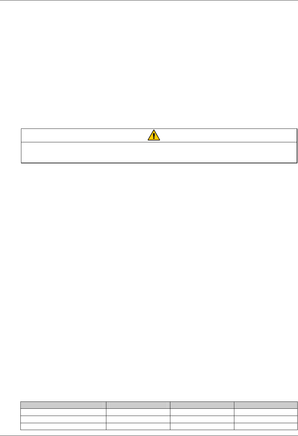
Chapter 6 Battery 47
HIPULSE U UPS Single Module And “1+N” (Expandable) 160/200/300/400kVA User Manual
adequate ventilation and heating of the cells. Boost charging must not be applied to valve regulated cells as this will
cause them to overcharge and subsequently vent.
Similarly, valve-regulated cells cannot be regarded as maintenance-free as they must be kept clean and their
connections checked periodically for tightness and lack of corrosion. Specific inspection instrument can also be used
to check each battery cell periodically to learn about the variation in capacity.
Batteries are fully charged before delivery; however, storage and transportation times mean that, inevitably, some
charge is lost by the time the battery is commissioned. All the cells forming the battery should be brought to the same
state of charge and be recharged within 6 months of the factory charge.
It is especially important that the battery is fully charged before attempting a witness test of the autonomy time. This
may require several days to complete; therefore any witness test concerning the batteries should take place only after
the battery has been on uninterrupted float charge for at least one week.
Cell performance typically improves after a few weeks in service or after two or three discharge and recharge cycles.
6.4 Installation Design Considerations
Note
Full safety instructions concerning the use and maintenance of UPS batteries are provided in the appropriate battery
manufacturers manuals. The battery safety information contained in this section relates to key considerations which must be taken
into account during the installation design process and might affect the design outcome depending on localized conditions.
6.5 Battery Installation And Maintenance
6.5.1 Temperature Considerations
Battery performance depends on the ambient battery temperature. Capacity and autonomy times are quoted for a
new battery operating at 20°C. Battery capacity is increased by 1% for every 1°C increase in temperature up to 25°C.
If a battery is used at temperatures above 25°C, its life is reduced; consequently its capacity and UPS autonomy time
will reduce more rapidly over a period of time. Operating below 20°C will reduce the battery capacity by
approximately 1% to 1.5% per 1°C. For example, if a battery discharge test is attempted during the middle of winter
when the ambient temperature is 5°C the battery capacity will be only 77.5% of its design value and will not satisfy its
specified autonomy time.
Ambient temperature, ventilation, spacing, float voltage and ripple current all affect the battery temperature. Uneven
temperature distribution through the battery string will cause the voltage distribution to be uneven which can also lead
to problems — it is therefore important to maintain an even temperature across the whole battery chain.
Valve-regulated cells are very sensitive to temperature and should be operated at a temperature between 15°C and
25°C. To help sustain this operating temperature range the battery is normally float charged at 2.25V/cell.
When batteries are cabinet-mounted adjacent to the UPS module, it is the battery which dictates the designed
maximum ambient temperature, not the UPS. That is, in the case of valve-regulated cells, the ambient room
temperature should be kept between 15°C and 25°C, and not between 0°C and 40°C (which is the specified main
equipment operating temperature range). Temperature excursions are permissible for short periods of time provided
the average temperature does not exceed 25°C.
6.5.2 Battery Population
The nominal DC bus voltage, and therefore battery float voltage, is set according the module’s rated input and output
voltages, and usually set to 432Vdc (380Vac), 446Vdc (400Vac) or 459V (415Vac). Given that the desired cell float
voltage is 2.25V, this means that a different number of cells are required in each case (see Table 6-1).
Table 6-1 Battery population
Parameter 380V 400V 415V
Number of cells used (standard) 192 pcs 198 pcs 204 pcs
End-of-discharge voltage 320V 330V 340V
Float voltage 432V 446V 459V

48 Chapter 6 Battery
HIPULSE U UPS Single Module And “1+N” (Expandable) 160/200/300/400kVA User Manual
6.6 Battery Protection
The battery is connected to the UPS through a BCB which is manually closed and electronically tripped through the
UPS control circuitry. If the cells are rack-mounted (or located remote from the main UPS cabinet), the BCB must be
mounted as near as possible to the batteries themselves, and the power and control cables connected to the UPS
using the most direct route possible.
Features of the BCB include:
z Isolation from battery to achieve safety and reliability
z Shortcircuit protection
z Automatic opening in the event of inverter lockup due to battery undervoltage to prevent battery damage caused
by overdischarge
z Tripping by remote emergency power off (EPO) button if installed
z Operation error protection
To achieve the required autonomy time, it may be necessary to parallel battery strings. In which case, the battery
circuit breaker should be placed downstream of all parallel battery strings.
Note: All equipment servicing procedures should be carried out only by trained personnel.
6.7 Battery Connection
6.7.1 Fitting The Batteries
1. In general a minimum space of 10 mm must be left on all vertical sides of the battery block to permit free air
movement around the cells.
2. A clearance of 150 mm should be allowed between the top of the cells and the underside of the shelf above (this is
necessary for monitoring and servicing the cells).
3. When installing the batteries always work from the bottom shelf upwards to prevent raising the center of gravity.
6.7.2 Connecting The Battery
1. All cabinets (or racks) must be earthed.
2. In general it is recommended that the inter-connecting cables be fitted to the batteries within their particular level
before fitting the inter-level connecting cables, followed finally by the cables to the circuit breaker.
3. An insulating shroud should be fitted to each terminal after its connection has been made.
4. When connecting the cables between the battery extremities to the circuit breaker always connect the circuit
breaker end of the cable first.
6.8 Battery Installation
Whatever the type of mounting system selected, the following conditions should be noted (see Figure 6-1):
X Layout of cells:
Whatever battery mounting system is used, the batteries should be laid out in such a manner as to make
simultaneous contact with two exposed live parts having a potential greater than 150V impossible. Where this is not
possible, insulated terminal shields must be installed and insulated cables must be used for connections.
Y Service platform:
The service platform (or duckboard) must be slip-proof, insulated from the floor and be at least one meter wide.
Z Connections:
All connections must be as short as possible.
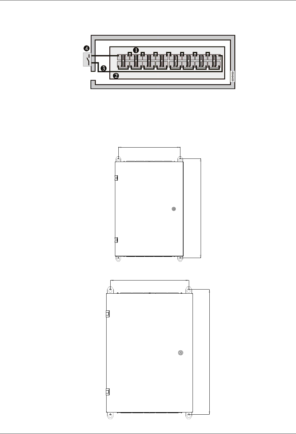
Chapter 6 Battery 49
HIPULSE U UPS Single Module And “1+N” (Expandable) 160/200/300/400kVA User Manual
[ BCB:
A BCB is generally installed in an enclosure on the wall close to the battery installation. The connection of BCB box
available for the HIPULSE U UPS is described in the following section.
Figure 6-1 Battery room design
6.9 BCB Box (Optional)
The battery circuit breaker (BCB) box of 160/200kVA UPS adopts wall mounting, while that of the 300/400kVA UPS
can adopt both wall mounting and floor mounting. The installation hole dimensions are shown in Figures 6-2 to 6-4.
455
738
Figure 6-2 Installation hole dimensions for wall mounting of BCB box of 160/200kVA UPS (unit: mm)
1042
654
Figure 6-3 Installation hole dimensions for wall mounting of BCB box of 300/400kVA UPS (unit: mm)
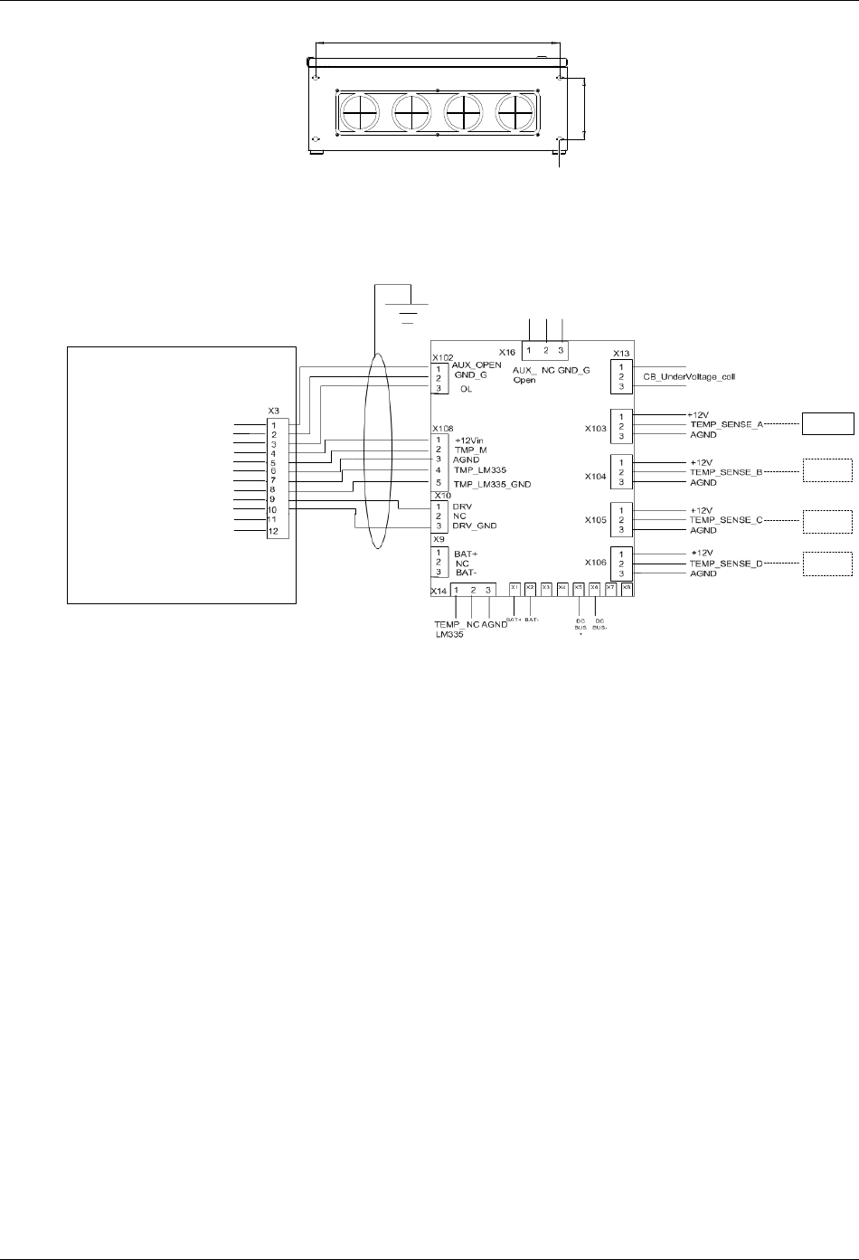
50 Chapter 6 Battery
HIPULSE U UPS Single Module And “1+N” (Expandable) 160/200/300/400kVA User Manual
660
167
4-Ф13 Knockout
Figure 6-4 Installation hole dimensions for floor mounting of BCB box of 300/400kVA UPS (unit: mm)
The battery circuit breaker (BCB) box contains a BCB and a BCB control board (ULK366SC1).
The BCB box is fitted as close as possible to the battery and connected to the UPS, as illustrated in Figure 6-5.
FB
GND
OL
+12V
TMP_T
GND
LM355+
LM355 + GND
DRV
DRV_ GND
NC
NC
BCB control board
UPS
TMP12Z
TMP12Z
TMP12Z
TMP12Z
BCB status feedback
BCB connection detection
Battery temperature sensing 1
Battery temperature sensing 2
BCB drive
Not connected
Figure 6-5 BCB box connection
Note: The control cables from the UPS to the BCB control board must be made using the accessory cable of the BCB,
which is a shielded cable located in a separate conduit to that containing the battery power cables. The cable shield
must be earthed to prevent induced noise affecting the control operation, and a separate safety earth must be
connected between the UPS and BCB box.
6.10 Battery Temperature Sensor (Optional)
A battery temperature sensor (model: TMP12Z) supplied separately from the BCB is connected with the UPS logic
through the BCB control board. For the connection, see Figure 6-5.
With this feature fitted, the nominal float voltage supplied to the battery is adjusted so as to be inversely proportional
to the ambient temperature of the battery cabinet or battery room. This prevents the battery being over charged at
high ambient temperatures.
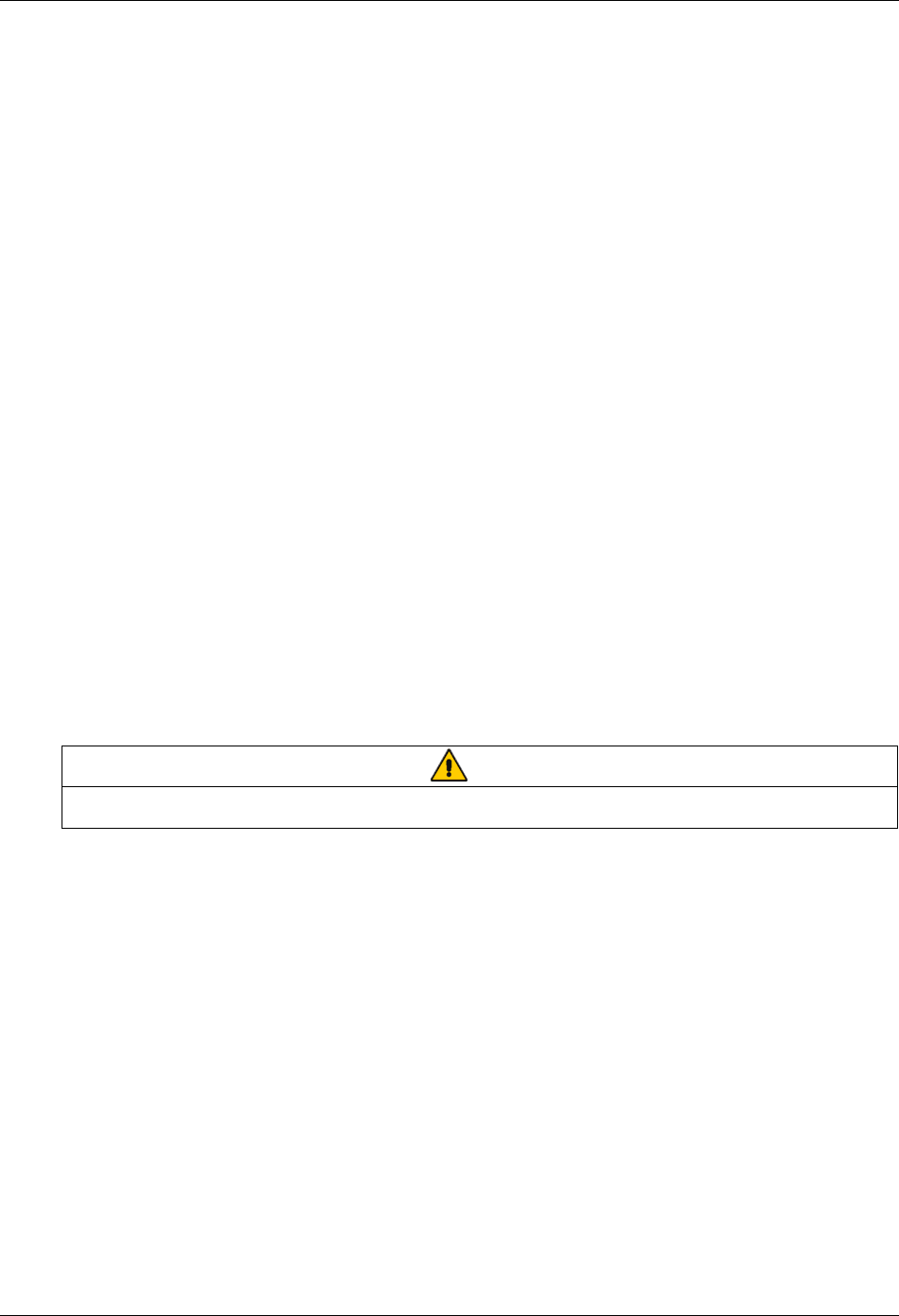
Chapter 7 “1+N” System 51
HIPULSE U UPS Single Module And “1+N” (Expandable) 160/200/300/400kVA User Manual
Chapter 7 “1+N” System
This chapter introduces the installation procedures, operating instructions of the “1+N” system, and the installation of
the dual bus system, of the HIPULSE U UPS.
7.1 General
The system can comprise of up to 6 UPS modules of the same power rating and connected in parallel without the
need for a centralized mains static bypass. Instead the bypass static switches of each UPS share the load when the
system transfers to the mains bypass supply.
From a ‘power’ viewpoint, each module is internally identical to the ‘single module’ configuration. A “1+N” system
requires inter-module control signals to manage the load sharing, synchronizing and bypass switching. The control
signals are connected through the parallel cables, which are multi-way ribbon cables connected between the units of
the system to form a ring.
When three or more modules are to be connected in parallel it is recommended that inductance should be inserted in
the static bypass line. This can be installed internal to the UPS as an option.
7.2 “1+N” System Installation Procedures
The basic installation procedure of a parallel system comprising two or more UPS modules is the same as that of
single module system. This section only introduces the installation procedures specific to the parallel system. The
installation of a parallel UPS must follow the installation procedure for a single UPS module with the additional
requirements detailed in this section.
7.2.1 Preliminary Checks
Be sure that a parallel kit is present and fitted in each of the modules, and that the modules are of the same rating
and with the same software and hardware release.
Warning
To achieve coordinated operation of the modules in the parallel system, it is required to configure each module separately using
background configuration software. This must be done by Emerson service & support trained personnel.
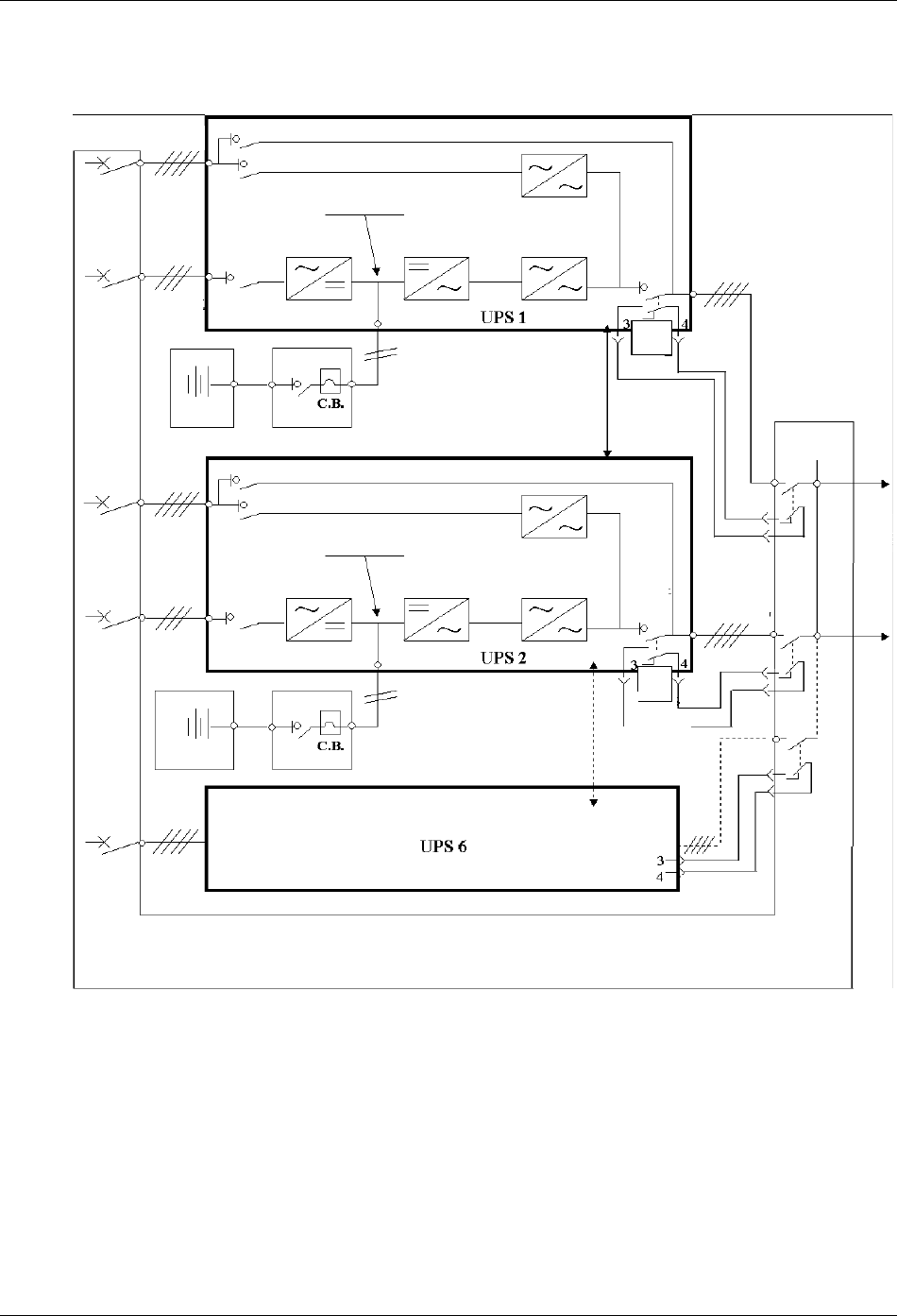
52 Chapter 7 “1+N” System
HIPULSE U UPS Single Module And “1+N” (Expandable) 160/200/300/400kVA User Manual
7.2.2 Cabinet Installation
Place the UPS modules side by side and interconnect as shown in Figure 7-1.
Q5
Parallel
board
J5
Q5
并机电缆
并机电缆
Bypass
mains supply
Maintenance bypass switch Q3
Bypass switch Q2
DC bus
Rectifier Inverter Static switch
Input switch Q1
Input mains
supply
Battery 1 BCB 1
Parallel cable
Bypass
mains supply
Input mains
supply
Output
switch Q5
UPS 1
output
Ext. Sw out
UPS 2 output
Parallel
board
J5
Output
switch
Q5
Ext. Sw out
UPS 6
output
Parallel board J5
Ext. Sw out
Distribution panel
Load
Maintenance bypass switch Q3
Bypass switch Q2
DC bus
Rectifier Inverter Static switch
Input switch Q1
BCB 2
Parallel cable
Battery 2
Input
distribution
Bypass side
Bypass side
Distribution
of load
Figure 7-1 “1+N” system block diagram
7.2.3 Protective Devices
Refer to the instructions supplied in 3.1.6 Protective Devices.
Note: Use of residual current detectors (RCDs) on UPS unit inputs requires installation of a common device only on
the system bypass mains.
7.2.4 Power Cables
Refer to the instructions supplied in 3.1 Power Cabling.
Note: The length and specification of power cables including the bypass input cables and UPS output cables should
be the same. This facilitates load sharing when operating in bypass mode.
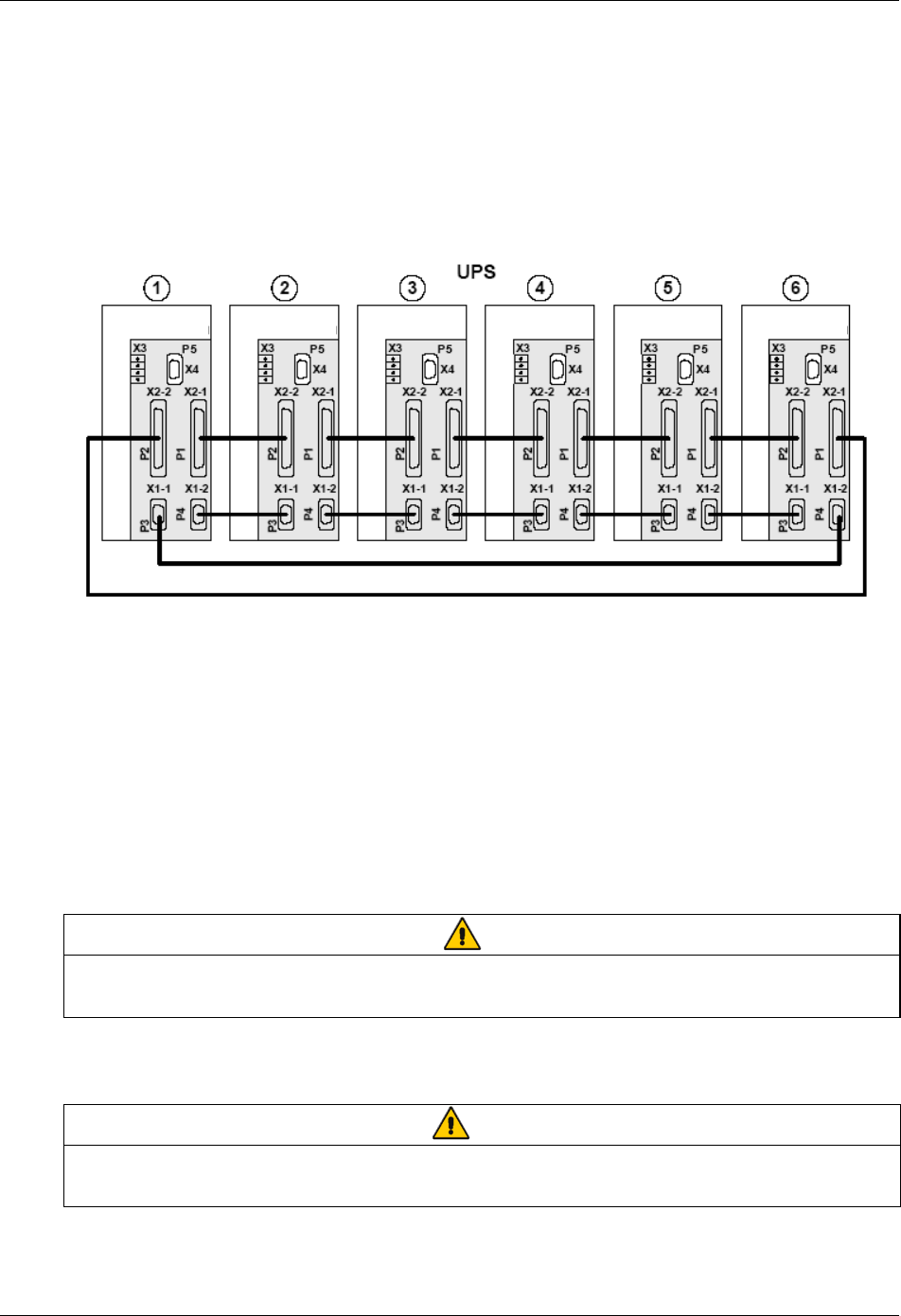
Chapter 7 “1+N” System 53
HIPULSE U UPS Single Module And “1+N” (Expandable) 160/200/300/400kVA User Manual
7.2.5 Control Cables
Parallel Cable
Shielded and double insulated control cables available in length up to 20 meters must be must be interconnected in a
ring configuration between UPS modules as shown in Figure 7-2. Specifically, connect the two parallel cables from
X1-1 and X2-2 on the parallel board of the first module respectively to X1-2 and X2-1 on the parallel board of the
second module, and so on.
The parallel board is mounted on the inner door of each UPS module. The ring configuration ensures high reliability
of the control.
Parallel board Parallel board Parallel board Parallel board Parallel board Parallel board
Figure 7-2 Connection of “1+N” system parallel cables
Emergency power off (EPO)
Refer to the EPO input port (X2) part in 3.3.1 Monitoring Board Ports.
Battery control
Refer to 3.3.2 Battery Control.
External bypass and output interlock
EXT-Maint (X3-1&2) on UPS parallel board M3 (leave open if no external bypass switch is used) provides external
maintenance bypass interlock protection for the UPS. Short circuit means external bypass closed.
EXT-Out (X3-3&4) on UPS parallel board M3 (leave shorted if no external output switch is used) provides external
output interlock protection for paralleled UPS modules. Short circuit means external output switch closed.
Note
UPS parallel board M3 is located behind protective covers accessible aftr opening the UPS front door — removal of this barrier
requires the use of a tool and is restricted to service personnel.
Jumper JP1 (located next to X3) needs to be removed for X3: 3&4 to work properly.
7.3 “1+N” System Operating Instructions
Warning
If residual current detectors (RCDs) are used on UPS unit inputs, use a common device only on the system’s bypass mains. At
the instant of electrical connection, the current may not be split instantaneously and this may cause the residual current circuit
breakers (RCCBs) to trip separately.
These operations must be performed one at a time, progressing to the next step only after having completed the
previous step on both UPS modules.
54 Chapter 7 “1+N” System
HIPULSE U UPS Single Module And “1+N” (Expandable) 160/200/300/400kVA User Manual
7.3.1 Start-Up Procedure (Into Normal Mode)
This procedure must be followed when turning on the UPS from a fully powered down condition, that is, where the
load is not being initially supplied at all or where supplied by the maintenance bypass switch. It is assumed that the
installation is complete, the system has been commissioned by authorized personnel and the external power isolators
are closed.
Refer to 5.2 Start-Up Procedure (Into Normal Mode).
7.3.2 Maintenance Bypass Procedure (And UPS Shut Down)
Warning
The internal maintenance bypass must not be used when the UPS system is comprised of more than two UPS modules in
parallel.
Refer to 5.6 Maintenance Bypass Procedure (And UPS Shut Down).
7.3.3 Switching OFF And Isolating One UPS While The Other Remains In Service
1. In sequence, open the UPS output switch Q5, input switch Q1, and bypass switch Q2.
2. Open the BCB inside the battery cabinet.
To completely isolate the UPS, open the AC power supply circuit breaker (both circuit breakers if separate supplies
are provided for the rectifier and the bypass supply) and the output circuit breaker on the power distribution
switchboard.
If individual UPS output isolation circuit breaker (and its auxiliary contacts) are not installed on the power distribution
switchboard, remember that voltage supplied by the others UPS which remains in service will still be present on the
output terminals of the shutdown UPS.
Warning
If individual UPS output isolation circuit breaker are not installed on the power distribution switchboard, remember that voltage
supplied by the others UPS which remains in service will still be present on the output terminals of the shutdown UPS.
Warning: Wait five minutes for the internal d.c bus bar capacitors to discharge.
7.3.4 Insertion Procedure (Of One Module In A Parallel System)
This procedure is indicated to re-integrate a UPS module that has been previously isolated from other modules of a
group of paralleled UPS modules. It is assumed that the installation is complete, the system has been commissioned
by authorized personnel and the external power isolators are closed.
1. Open the UPS door to gain access to the power switches.
2. Open (or confirm disabled) maintenance bypass switch Q3.
3. Close the bypass switch Q2, output switch Q5, and any external output isolation switches (where used). The LCD
display becomes active.
4. Close the input switch Q1.
The rectifier LED flashes on the operator control and display panel during the startup of rectifier and becomes steady
green once the rectifier reaches normal operation state after about 15 seconds.
5. Close the external BCB. This breaker is located inside the battery cabinet (if used) or is otherwise adjacent to the
battery racks.
6. Following battery availability being detected by the UPS, the red battery LED extinguishes moments after when the
battery charger starts operation.
7. Press and hold the INVERTER ON button for two seconds.
The inverter will start up and the inverter LED flashes while it synchronizes to the load voltage frequency. After the
inverter is ready, the UPS connects to the load, the inverter LED becomes steady green and the load LED turns
green.
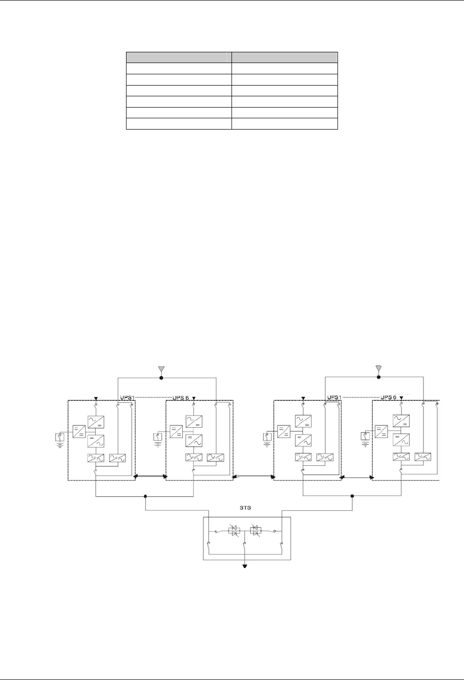
Chapter 7 “1+N” System 55
HIPULSE U UPS Single Module And “1+N” (Expandable) 160/200/300/400kVA User Manual
8. Check that no warning message is displayed in the top right corner of the LCD screen and the status of the LEDs
as follows:
Table 7-1 LED status
LED Status
Rectifier LED Steady green
Bypass LED Off
Battery LED Off
Inverter LED Steady green
Load LED Steady green
Alarm LED Off
7.3.5 Shutdown Procedure (Complete UPS And Load Shutdown)
Refer to 5.7 Shutdown Procedure (Complete UPS And Load Shutdown).
7.4 Dual Bus System Installation Procedures
7.4.1 Cabinet Installation
As shown in Figure 7-3, the dual bus system consists of two independent UPS configurations each consisting of one
or more UPS modules. Dual bus systems are high availability configurations suitable for loads with multiple input
terminals. For single input loads an optional static transfer switch (STS) may be added.
The objective of the dual bus system is to keep the output of two independent UPS systems (or parallel systems) in
synchronization using optional load bus synchronization (LBS) cable. One system is designated as the master; the
other is designated as the slave. The operating modes covered comprise master and or slave operating inverter or
bypass mode.
In installation, place the UPS modules side by side and interconnect as described in the following sections.
制电缆
Bypass supply
Input rectifier Input rectifier
Parallel
cable
LBS
cable
Parallel
cable
Load
Bypass supply
Input rectifier Input rectifier
Figure 7-3 Typical dual bus system (using STS and LBS cable)
7.4.2 Protective Devices
Refer to 3.1.6 Protective Devices.
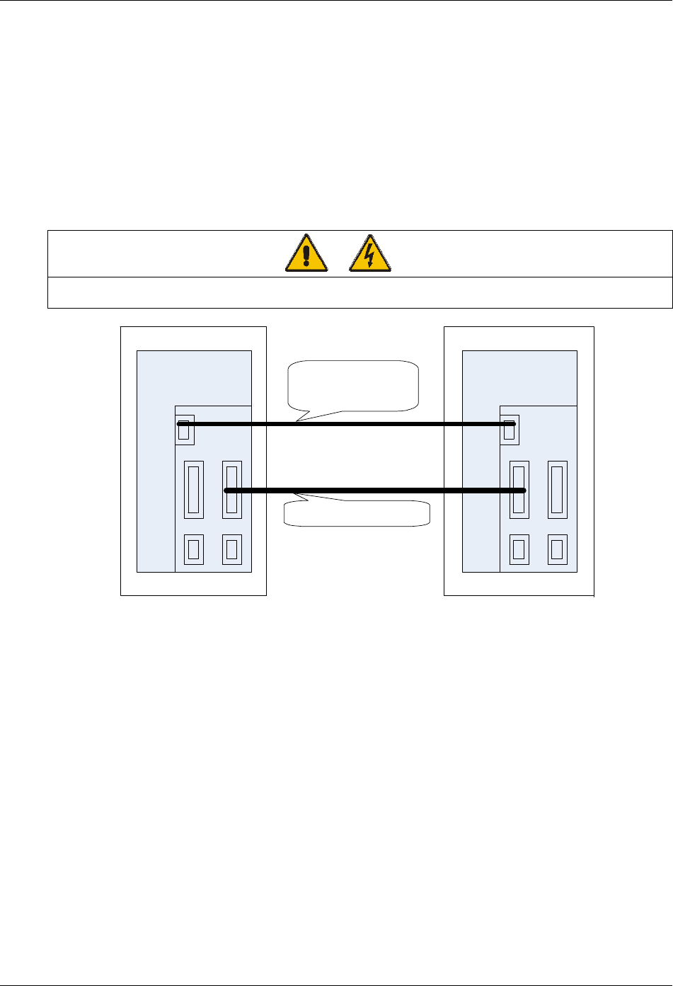
56 Chapter 7 “1+N” System
HIPULSE U UPS Single Module And “1+N” (Expandable) 160/200/300/400kVA User Manual
7.4.3 Power Cables
The wiring of power cables is similar to that of single module system. Refer to 3.1 Power Cabling.
The bypass and the main input sources must be referenced to the same neutral potential and input earth leakage
monitoring devices, if installed, must be located upstream of the common neutral sinking point.
7.4.4 Control Cables
Control cable connection of dual bus system consisting of two single units
If the dual bus system consists of two single units, use the optional 9-core LBS cable to connect between the LBS
interfaces (X4 socket on parallel board) of the two single units, and use another optional LBS cable to connect
between any two 25-core interfaces (X2-1 or X2-2) of the two single units, as shown in Figure 7-4.
Warning
Although the dedicated 25-core LBS cable looks like the parallel cable, it is absolutely not the parallel cable, and cannot be
replaced by it. Otherwise, UPS system chaos may occur.
Parallel board
X4
04116319 20m DB9-DB9
04115338 10m DB9-DB9
04115339 15m DB9-DB9
04116100 15m DB25-DB25
Parallel board
UPS unit 1 UPS unit 2
LBS cable
LBS cable X4
X2-1 X2-2
X1-2X1-1
X2-1 X2-2
X1-2X1-1
Figure 7-4 Control cable connection of dual bus system consisting of two single units
Control cable connection of dual bus system consisting of a single unit and a parallel system
Figure 7-5 shows the control cable connection of the dual bus system consisting of a single unit and a parallel system
composed of two or more single units. Use the optional 9-core LBS cable to connect from the LBS interface (X4
socket on parallel board) of the single unit to the LBS interface of any single unit in the parallel system; and use
another optional LBS cable to connect from any 25-core interface (X2-1 or X2-2) of the single unit to the LBS
interface of any single unit except for the aforesaid one in the parallel system, note that this LBS cable has a 9-core
end and a 25-core end, respectively connecting the X4 interface of the parallel system and the 25-core interface of
the single unit.
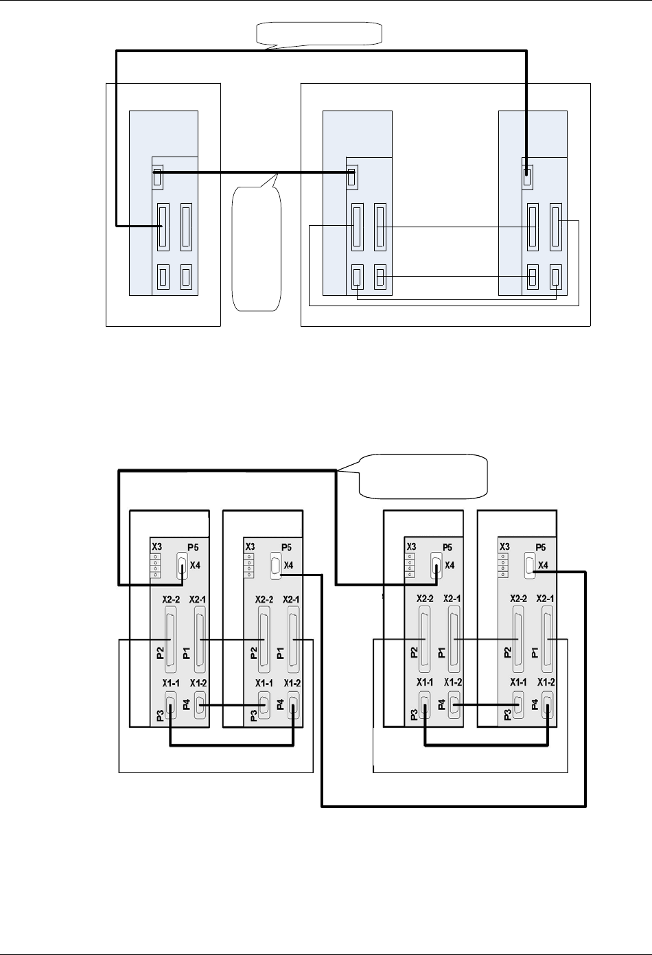
Chapter 7 “1+N” System 57
HIPULSE U UPS Single Module And “1+N” (Expandable) 160/200/300/400kVA User Manual
Parallel board
X2-1 X2-2
X1-2
X1- 1
X4
04116113 15m DB9-DB25
04116319 20m DB9-DB9
04115338 10m DB9-DB9
04115339 15m DB9-DB9
Parallel board
Parallel
board
LBS cable
Parallel cable
Parallel cable
Parallel cable
UPS parallel system
UPS unit
LBS cable
X4
X2-1 X2-2
X1-2
X1-1
X4
X2-1 X2-2
X1-2
X1-1
X4
X2-1 X2-2
X1-2
X1-1
Figure 7-5 Control cable connection of dual bus system consisting of a single unit and a parallel system
Control cable connection of dual bus system consisting of two parallel systems
For the dual bus system consisting of two parallel systems respectively composed of two or more single units, you
must form a ring connection between the two parallel systems with the optional 9-core LBS cables. The connection
interfaces are the X4 sockets on the parallel boards, as shown in Figure 7-6.
并机板 并机板 并机板 并机板
并机系统1并机系统2
DBS 电缆
AB
LBS电缆
并机电缆并机电缆
UPS并机系统1UPS并机系统2
04116319 20m DB9-DB9
04115338 10m DB9-DB9
04115339 15m DB9-DB9
LBS电缆
04115338 10m DB9-DB9
04116319 20m DB9-DB9
04115339 15m DB9-DB9
Parallel board Parallel board Parallel board Parallel board
LBS cable
LBS cable
Parallel cableParallel cable
UPS parallel system 2UPS parallel system 1
Figure 7-6 Control cable connection of dual bus system consisting of two parallel systems

58 Chapter 8 Specifications
HIPULSE U UPS Single Module And “1+N” (Expandable) 160/200/300/400kVA User Manual
Chapter 8 Specifications
This chapter provides the specifications of the HIPULSE U UPS.
8.1 Conformity And Standard
Table 8-1 Conformity and standard
Description Year Normative references
Safety requirements 1999 IEC60950-1, IEC62040-1-1, UL1778
EMC 2005 IEC/EN62040-2
Design and test methods 1999 IEC62040-3
8.2 Environmental Requirements
Table 8-2 Environmental requirements
Power rating (kVA)
Item Unit 160 200 300 400
Operating Temperature °C 0~40
Maximal temperature for 8hr day °C 40°C (derate power by 1.5% per °C between 40°C and 50°C
Mean Temperature for 24hr °C Maximally 35
Relative humidity - ≤95% at 20°C
Altitude of operation m ≤1000m asl (derate power by 1% per 100m between 1000m and 2000m)
Storage temperature and transport
temperature °C -25 to 70
8.3 Mechanical Characteristics
Table 8-3 Mechanical characteristics
Power rating (kVA)
Item Unit 160
(6-pulse)
160
(12-pulse)
200
(6-pulse)
200
(12-pulse)
300
(6-pulse)
300
(12-pulse)
400
(6-pulse)
400
(12-pulse)
Height mm 1900
Width mm 1250 1640 1250 1640 1640 2280 2280 2280
Depth mm 875
Weight kg 1200 1725 1350 2000 1600 2200 2100 2750
Ventilation - By internal intake fans
Airflow m3/h 2590 2750 2750 2910 5350 5350 6150 6150
Cable entry - Bottom or either side (top optional)
8.4 Electrical Characteristics (Input Rectifier)
Table 8-4 Electrical characteristics (input rectifier)
Power rating (kVA)
Item Unit 160
(6-pulse)
160
(12-pulse)
200
(6-pulse)
200
(12-pulse)
300
(6-pulse)
300
(12-pulse)
400
(6-pulse)
400
(12-pulse)
Rated mains voltage Vac 380, 400, or 415
Supply - Three phase without neutral
Input voltage
tolerance 1 % ±15, (maxmally, from 290Vac to 498Vac)
Frequency Hz
50 or 60
Input frequency
tolerance Hz 45~65

Chapter 8 Specifications 59
HIPULSE U UPS Single Module And “1+N” (Expandable) 160/200/300/400kVA User Manual
Power rating (kVA)
Item Unit 160
(6-pulse)
160
(12-pulse)
200
(6-pulse)
200
(12-pulse)
300
(6-pulse)
300
(12-pulse)
400
(6-pulse)
400
(12-pulse)
Rated input power 2 kVA 197 191 245 236 365 354 488 469
Rated input current2 A 298 289 371 358 551 535 739 708
Maximal input Power3 kVA 246 239 306 295 420 407 609 584
Maximal input
current3 A 373 362 464 447 634 616 931 885
Duration of
progressive power
walk-in4 s 5~300
Note:
1. With mains at -15% and suggested battery elements the UPS maintains the output rated voltage at rated load but cannot
guarantee float charge to battery; the battery does not discharge.
2. IEC62040-3 (5.2.2): UPS, rated load, input rated voltage 380V, no current to battery.
3. IEC62040-3 (5.2.2): UPS, rated load or overload, input rated voltage 380V, battery on boost charge with maximal allowed
current.
4. Set by dedicated background software
8.5 Electrical Characteristics (DC Intermediate Circuit)
Table 8-5 Electrical characteristics (DC intermediate circuit)
Power rating (kVA)
Item Unit 160 200 300 400
Voltage range for inverter operation Vdc 320~490
Recommended number of lead-acid cells 1,2 pcs
192 (380Vac)
198 (400Vac)
204 (415Vac)
Recommended float charge voltage 2.25V/el.1 Vdc
432 (380Vac)
446 (400Vac)
459 (415Vac)
Recommended boost charge voltage 2.35V/el.1 Vdc
451 (380Vac)
465 (400Vac)
479 (415Vac)
Maximum voltage on manual charge 2.40 V/el.1 Vdc
461 (380Vac)
475 (400Vac)
490 (415Vac)
End-of-discharge voltage 2.45V/el.1 Vdc
471 (380Vac)
485 (400Vac)
500 (415Vac)
Max boost charge duration 3 min 480~1800
Freshening charge duration3 h 1~36
Boost-float threshold current 3 A 0.001C~0.025C
Ripple voltage superimposed 4 % ≤1
Note:
1. (According to rated voltage).
2. Factory set for rated 380V, different cells number and voltage per cell may be set by configuration software.
3. Set by software.
4. Battery disconnected, RMS percentage value referred to DC voltage
60 Chapter 8 Specifications
HIPULSE U UPS Single Module And “1+N” (Expandable) 160/200/300/400kVA User Manual
8.6 Electrical Characteristics (Inverter Output)
Table 8-6 Electrical characteristics (inverter output)
Power rating (kVA)
Item Unit 160 200 300 400
Rated mains voltage1 Vac 380, 400, or 415
Supply - Three phase with neutral
Frequency2 Hz 50 or 60
Rated Power at cos = 0.9 kVA 160 200 300 400
Rated Power at cos = 1 kW 144 180 270 360
Three-phase transient overload3 Min,
I/In
60, 1.10
10, 1.25
1, 1.5
Maximal non linear load allowed4 - 100%Pn
Voltage stability, steady State test3 % ±1
Voltage stability, transient test 5 % ±5
Maximum rate of charge of frequency6 Hz/s 0.1
Note:
1. Factory set 380V 400 or 415 voltages with software setting.
2. Factory set at 50Hz 60 Hz with software setting.
3. IEC62040-3 (5.3.2).
4. IEC62040-3 (ANNEX E).
5. IEC62040-3 (5.3.1), also for 0~100~0%, load transient, restore time 20 ms to 1%.
6. Factory set at 0.1Hz/s; up to 1Hz/s with software setting
8.7 Electrical Characteristics (Bypass Input Mains)
Table 8-7 Electrical characteristics (bypass input mains)
Power rating (kVA)
Item Unit 160 200 300 400
Rated mains voltage1 Vac 380, 400, or 415
Supply - Three phase with neutral
243 304 456 607
231 289 433 577
Rated current
380Vac
400Vac
415Vac
A
222 278 416 554
Bypass voltage tolerance2 % Default upper limit: 15%; default lower limit: -20%
Delay time to recognise bypass
voltage returned to window s 2
Inverter output voltage window % ±5
Frequency3 Hz 50 or 60
Input frequency tolerance 4 % ±5
Maximum frequency slew rate Hz/s 1
Current rating of neutral cable - 1.3In
Protection, bypass line - The bypass line should be protected using an external device in the input distribution
system. This device should be sized to discriminate with the load protection
Transient overload ms
I/In
10
14.3
20
12.6
50
11.0
100
10.0
200
9.0
500
8.0
1000
7.1
2000
6.6
5000
5.7
Note:
1. Factory set 380V. 400 or 415 voltages with software setting.
2. Other values in -20%~15% with software setting.
3. Factory set at 50Hz 60 Hz with software setting.
4. Other values -5%~5%with software setting

Chapter 8 Specifications 61
HIPULSE U UPS Single Module And “1+N” (Expandable) 160/200/300/400kVA User Manual
8.8 Electrical Characteristics (System Performance)
Table 8-8 Electrical characteristics (system performance)
Power rating (kVA)
Item Unit 160
(6-pulse)
160
(12-pulse)
200
(6-pulse)
200
(12-pulse)
300
(6-pulse)
300
(12-pulse)
400
(6-pulse)
400
(12-pulse)
No load losses kW 2.75 3.30 3.50 4.15 3.90 4.65 4.70 6.51
Full load losses
(100%) kW 9.63 11.89 11.12 13.91 19.33 21.8 28.2 31.6
8.9 Electrical Characteristics (ECO Mode)
Table 8-9 Electrical characteristics (ECO mode)
Power rating (kVA)
Item Unit 160
(6-pulse)
160
(12-pulse)
200
(6-pulse)
200
(12-pulse)
300
(6-pulse)
300
(12-pulse)
400
(6-pulse)
400
(12-pulse)
Full load
losses (100%) kW 2.97 3.52 3.55 4.20 5.23 5.91 7.10 8.96

62 Chapter 9 Service & Maintenance
HIPULSE U UPS Single Module And “1+N” (Expandable) 160/200/300/400kVA User Manual
Chapter 9 Service & Maintenance
Regular service and maintenance are required during the long term operation of the UPS system (including the
associated battery). The battery maintenance is expounded in chapter 6. This chapter deals with the life
characteristics of the key components of the UPS, and provides recommendation for the regular check and service of
the key components. Proper service and maintenance of the UPS system can extend the UPS life and reduce the risk
of system malfunction.
9.1 Safety
Warning
The daily patrol check of the UPS system can be conducted by trained personnel, while the check and replacement of the UPS
components should be done by authorized professionals.
9.2 UPS Key Components And Their Lives
During the UPS operation, some UPS components’ lives are shorter than the UPS life due to wear and tear in
working. To ensure the safe power supply of the UPS system, regular check and replacement of these components
are required. This section introduces the key components of the HIPULSE U series UPS and their reference working
lives. For systems working in different conditions (environment, load, and so on), you may ask professionals to
assess the components and provide advices whether to replace the components by referring to the information
provided in this section.
9.2.1 Magnetic Components: Transformer, Inductor
The design life of the magnetic components is 20 years. The key factors affecting the life of the magnetic components
are the interwinding isolation system and the temperature increase in operation. The HIPULSE U series UPS adopts
H-level isolation system and can withstand up to 220°C working temperature. Normally, the UPS works in forced air
cooling condition.
9.2.2 Power Semiconductor Devices
The power semiconductor devices include SCR (silicon-controlled rectifier) and IGBT (insulated gate bipolar
transistor). In normal UPS working condition, there is no rated life of the power semiconductor devices. The SCR and
IGBT failures are always caused by other problems, as they do not have the problem of life expiration. However, in
system service and maintenance, you should check on an annual basis the appearances of the power semiconductor
devices for erosion and damage. If you spot any risk of failure , replace the device.
9.2.3 Electrolytic Capacitors
The life of the electrolytic capacitors depend on the DC bus voltage and ambient temperature of the UPS.
To ensure safe and stable UPS operation, it is recommended to check the operation status of the electrolytic
capacitors on an annual basis. The electrolytic capacitors must be replaced before their life expires, advisably, within
5 to 6 years of operation.
9.2.4 AC Capacitors
It is recommended to replace the AC capacitors within 5 to 6 years of continuous operation, and to check the AC
capacitors on a half year basis. Replace the AC capacitor if spotting any deformation.

Chapter 9 Service & Maintenance 63
HIPULSE U UPS Single Module And “1+N” (Expandable) 160/200/300/400kVA User Manual
9.2.5 Lives And Recommended Replacement Time Of Key Components
The key components listed in Table 9-1 are used in the UPS. To prevent system malfunction caused by failure of key
components due to wear and tear during working, you are recommended to check them regularly, and replace them
within their life expectancy.
Table 9-1 Lifves and recommended replacement time of key components
Key components Life expectancy Recommended replacement time Recommended check period
AC capacitor ≥7 years (~62,000hr) 5~6 years 6 months
Electrolytic capacitor ≥7 years (~62,000hr) 5~6 years 1 year
Fan ≥7 years (~62,000hr) 5~6 years 1 year
Air filter 1~3 years 1~2 years 3 months
Valve-regulated lead-acid
battery ( 5 years of life) 5 years 3~4 years 6 months
Valve-regulated lead-acid
battery ( 10 years of life) 10 years 6~8 years 6 months
9.2.6 Replacing Fuses
When replacing the fuse on the high-voltage interface board or the fuse in the fuse box, use a fuse of the same model,
avoid being misled by the parameter screenprint on the fuse box.
380V systems can use both 380V/4A fuse and 500V/4A fuse, while 400V/415V systems can use 500V/4A fuse only.
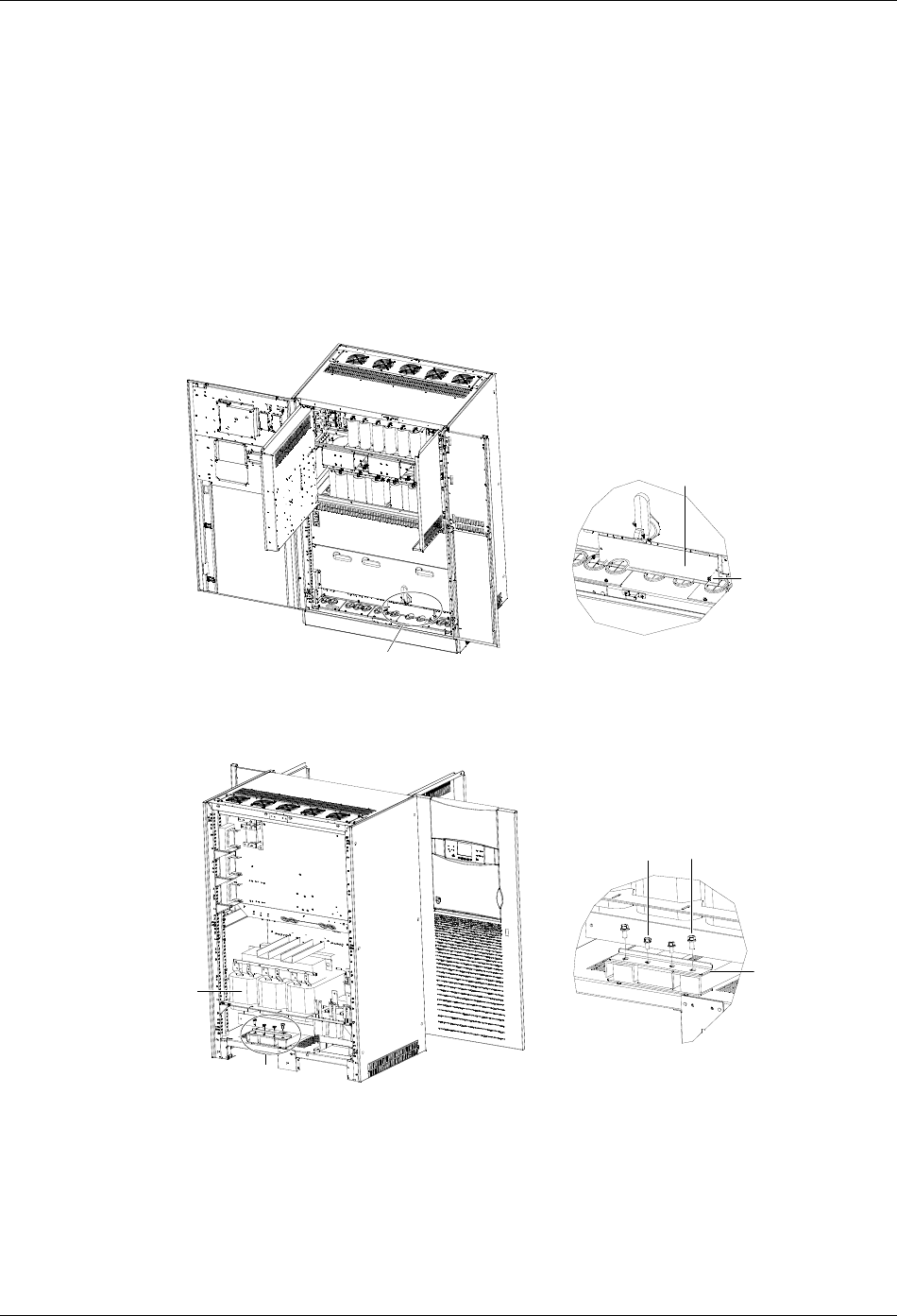
64 Appendix 1 Transportation Restraints Removing Procedures
HIPULSE U UPS Single Module And “1+N” (Expandable) 160/200/300/400kVA User Manual
Appendix 1 Transportation Restraints Removing Procedures
1. 160kVA&200kVA UPS Transportation Restraints Removing
Procedures
Transformer transportation restraints removing procedures for UPS with 6-pulse rectifier
1. Open the front door of the cabinet, remove the lower switch baffle plate and the installation hole cover, as shown in
Figure 1. Retain the screws.
AA放大处图
螺钉
安装孔盖板
Installation
hole cover
Screw
AA amplified view
Figure 1 Removing the installation hole cover
2. Remove the back panel of the cabinet to reveal the output transformer, as shown in Figure 2. Retain the screws.
A放大处图
出器输变压
固定件
M12螺栓
M10螺栓
AA amplified view
A
Output
transformer
Transportation
restraint
M10 bolt M12 bolt
Figure 2 Removing the output transformer transportation restraints
3. There is a transportation restraint respectively in the front and at the back at the bottom of the output transformer.
The one at the back is shown in Figure 2. Remove the fixing bolts of the one at the back, including two M10 bolts in
the middle and two M12 bolts at sides; then, remove the fixing bolts, including two M10 bolts in the middle and two
M12 bolts at sides, of the transportation restraint in the front through the installation hole revealed in step 1.
4. Remove the two transportation restraints, and install the four M12 bots removed in step 3 in their original positions.
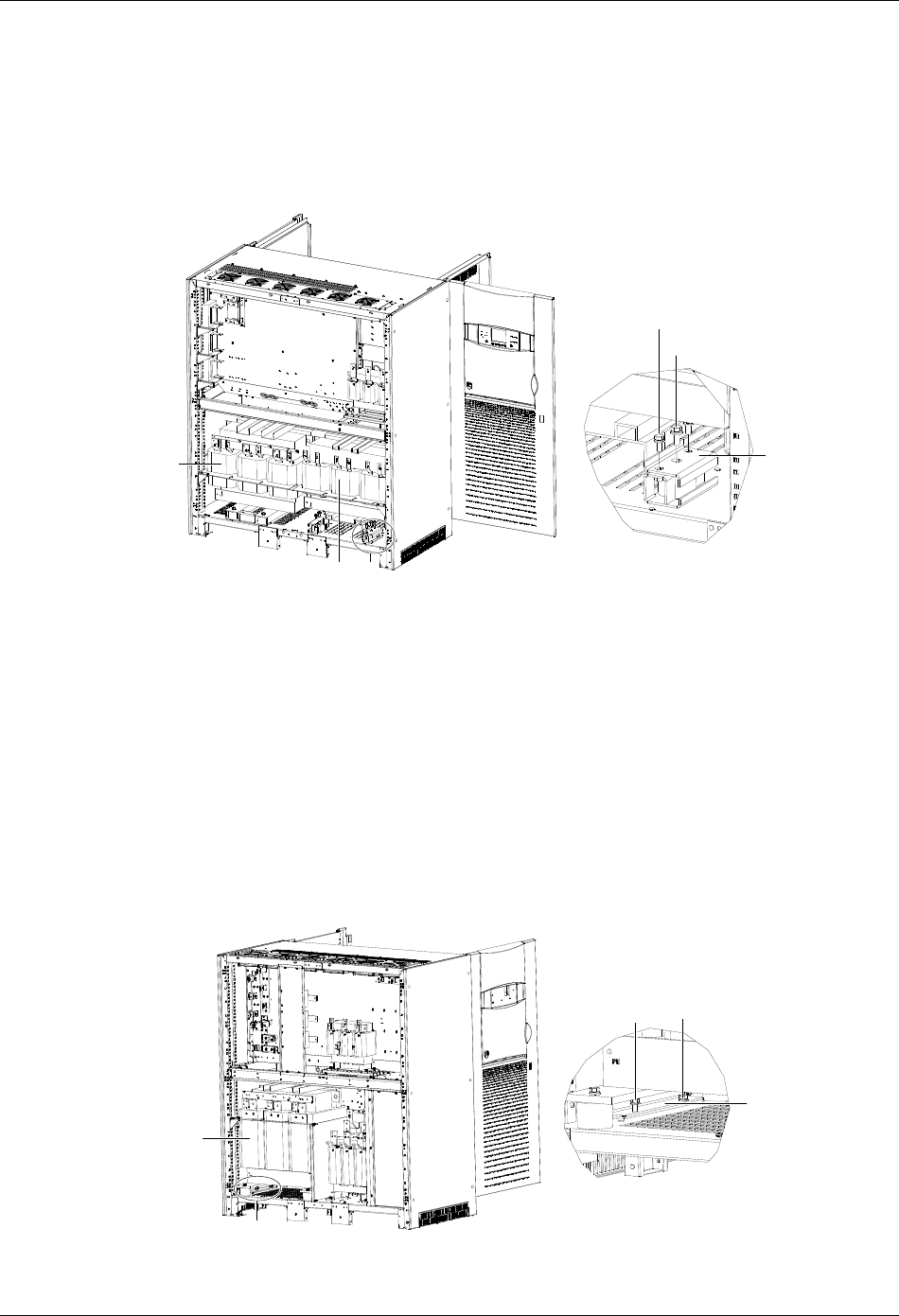
Appendix 1 Transportation Restraints Removing Procedures 65
HIPULSE U UPS Single Module And “1+N” (Expandable) 160/200/300/400kVA User Manual
5. Reinstall the installation hole cover and the lower switch baffle plate with the screws removed in step 1. You might
as well install the lower switch baffle plate after UPS commissioning.
6. Reinstall the back panel of the cabinet with the screws removed in step 2. You can also carry out this step after
UPS commissioning.
Transformer transportation restraints removing procedures for UPS with 12-pulse rectifier
1. Repeat the preceding steps 1 through 4 to remove the transportation restraints of the output transformer (see
Figure 3).
M12螺栓
M10螺栓
A放大处图
出器输变压 固定件
A移相 器变压 A
A amplified view
Output
transformer
Phase-shifting
transformer
M10 bolt
M12 bolt
Transportation
restraint
Figure 3 Removing the transformer transportation restraints
2. Remove the transportation restraints of the phase-shifting transformer.
There are two transportation restraints respectively in the front and at the back, totally four, at the bottom of the
phase-shifting transformer. Remove the two M10 bots at both sides and one M12 bolt in the middle of each
transportation restraint, as shown in Figure 3. Remove the four transportation restraints, and then reinstall the four
M12 bolts in their original positions.
3. Repeat the preceding steps 5 and 6.
2. 300kVA UPS Transportation Restraints Removing Procedures
Transformer transportation restraints removing procedures for UPS with 6-pulse rectifier
1. Remove the back panel of the cabinet to reveal the output transformer, as shown in Figure 4. Retain the screws.
A放大处图
出器输变压
固定件
M10螺栓
A
A
A amplified view
Output
transformer
M10 bolts
Transportation
restraint
Figure 4 Removing the output transformer transportation restraints
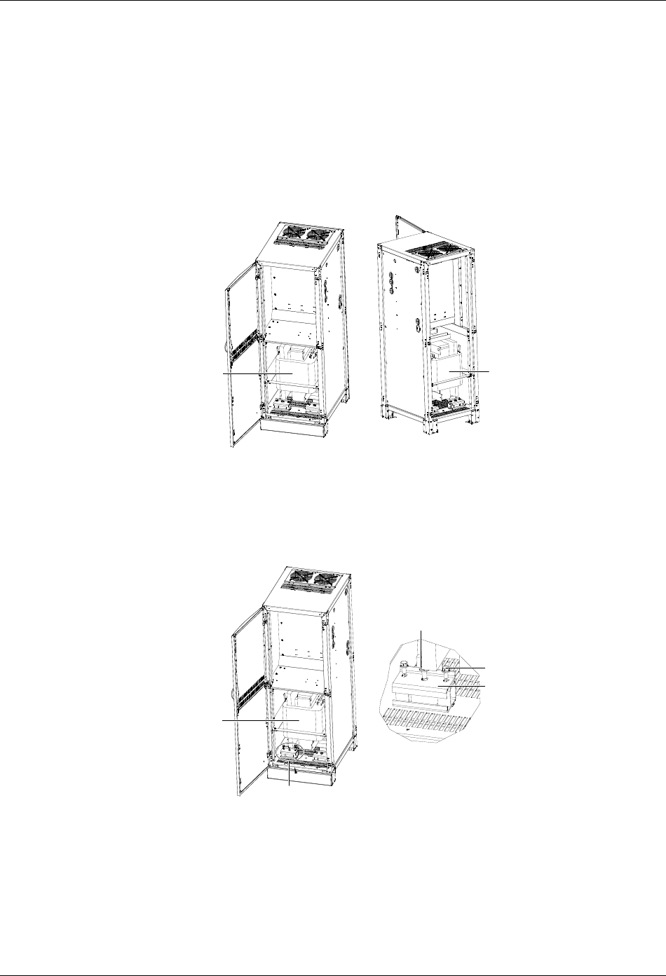
66 Appendix 1 Transportation Restraints Removing Procedures
HIPULSE U UPS Single Module And “1+N” (Expandable) 160/200/300/400kVA User Manual
2. There is a transportation restraint respectively on the right side and left side at the bottom of the output transformer.
Remove the two M10 bolts of each transportation restraint, as shown in Figure 4.
3. Reinstall the back panel of the cabinet with the screws removed in step 1. This step can also be done after UPS
commissioning.
Transformer transportation restraints removing procedures for UPS with 12-pulse rectifier
The removing procedures of the output transformer transportation restraints of 300kVA UPS with 12-pulse rectifier are
the same as those of 300kVA UPS with 6-pulse rectifier. The removing procedures of the transportation restraints of
the phase-shifting transformer are as follows:
1. Open the front door and remove the back panel of the side cabinet to reveal the phase-shifting transformer, as
shown in Figure 5. Retain the screws.
打前板开门 打后板开门
移相 器变压 移相 器变压Phase-shifting
transformer
Phase-shifting
transformer
Open the front door Open the back door
Remove the back panel
Figure 5 Opening the front door and removing the back panel
2. There are two transportation restraints respectively in the front and at the back, totally four, at the bottom of the
phase-shifting transformer. Remove the two M10 bots at both sides and one M12 bolt in the middle of each
transportation restraint, as shown in Figure 6. Remove the four transportation restraints, and then reinstall the four
M12 bolts in their original positions.
移相 器变压
A放大处图
固定件
M12螺栓
M10螺栓
A
Phase-shifting
transformer
A
A amplified view
M10 bolt
M12 bolt
Transportation
restraint
Figure 6 Removing the phase-shifting transformer transportation restraints
3. Reinstall the front and back doors of the side cabinet with the screws removed in step 1. This step can also be
done after UPS commissioning.
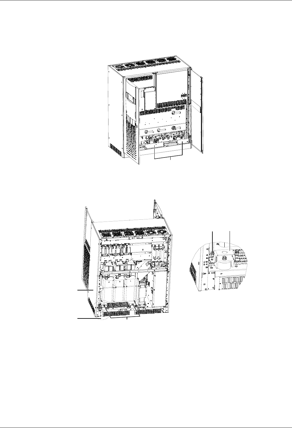
Appendix 1 Transportation Restraints Removing Procedures 67
HIPULSE U UPS Single Module And “1+N” (Expandable) 160/200/300/400kVA User Manual
3. 400kVA UPS Transportation Restraints Removing Procedures
Transformer transportation restraints removing procedures for UPS with 6-pulse rectifier
1. Open the front door of the main cabinet, remove the lower switch baffle plate and the installation hole covers, as
shown in Figure 7. Retain the screws.
Installation hole covers
Figure 7 Removing the installation hole covers
2. Remove the back panel of the main cabinet to reveal the output transformer, then remove the two transportation
restrains at the back of the output transformer, as shown in Figure 8.
Output transf ormer
ATransportation restraints
Bolt (2 pcs) Transportation restraint
A amplified view
Figure 8 Removing the two transportation restraints at the back
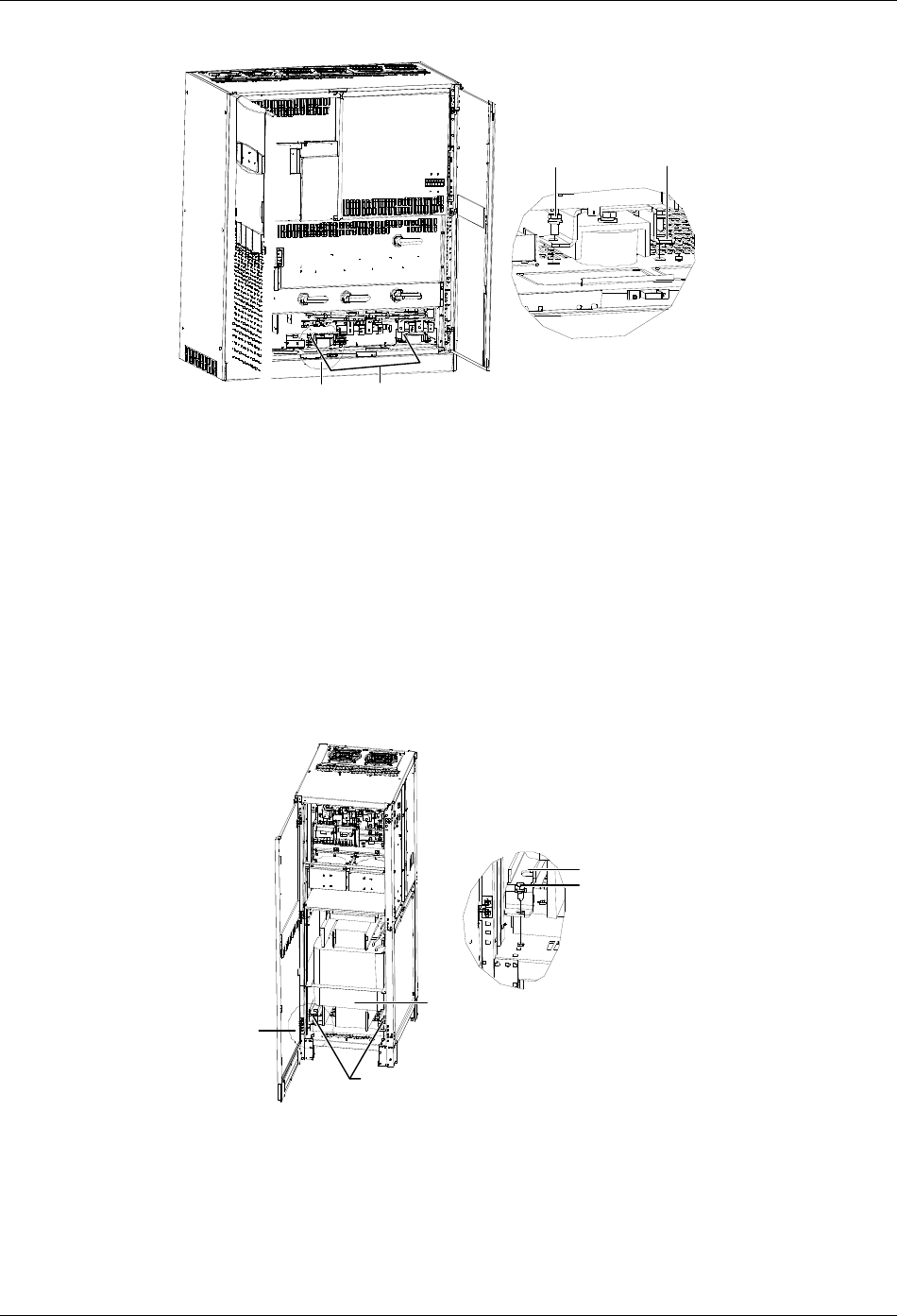
68 Appendix 1 Transportation Restraints Removing Procedures
HIPULSE U UPS Single Module And “1+N” (Expandable) 160/200/300/400kVA User Manual
3. Remove the two transportation restrains in the front of the output transformer, as shown in Figure 9.
A
A amplified view
Bolt (2 pcs) Transportation restraint
Transportation restraints
Figure 9 Removing the two transportation restraints in the front
4. Reinstall the installation hole covers and the lower switch baffle plate with the screws removed in step 1. You might
as well install the lower switch baffle plate after UPS commissioning.
5. Reinstall the back panel of the main cabinet with the screws removed in step 2. You can also carry out this step
after UPS commissioning.
Transformer transportation restraints removing procedures for UPS with 12-pulse rectifier
The removing procedures of the output transformer transportation restraints of 400kVA UPS with 12-pulse rectifier are
the same as those of 400kVA UPS with 6-pulse rectifier. The removing procedures of the transportation restraints of
the phase-shifting transformer are as follows:
1. Open the front door and remove the back panel of the side cabinet to reveal the phase-shifting transformer, as
shown in Figure 10. Retain the screws.
2. Remove the two transportation restraints in the front of the phase-shifting transformer, as shown in Figure 10.
Phase-shifting
transformer
Remove the tw o bolts fixing
the transportation restraint
A
Transportation restraint
Bolt
A amplified view
Figure 10 Removing the two transportation restraints in the front
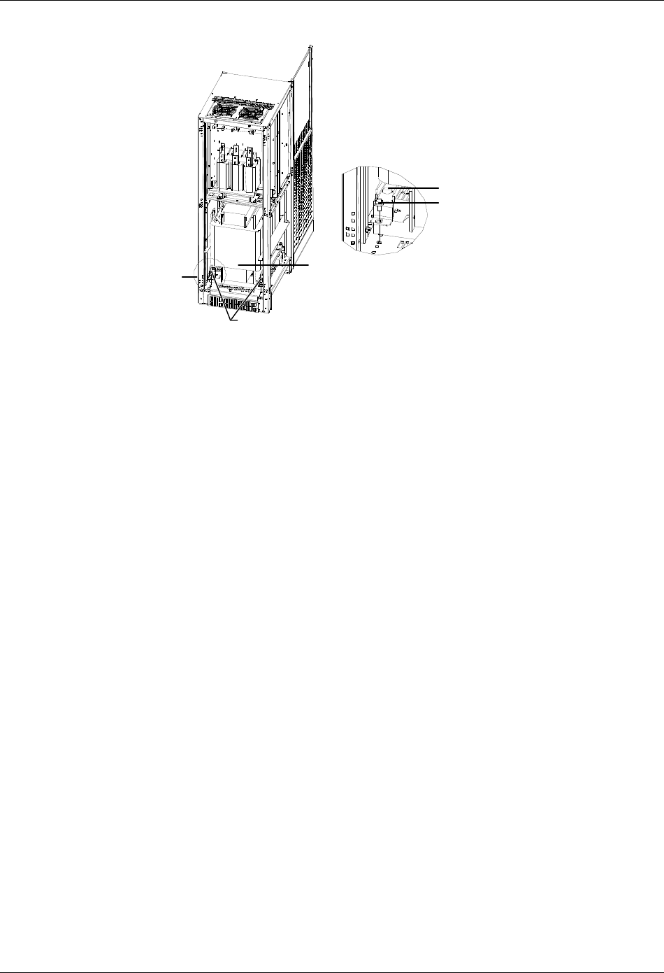
Appendix 1 Transportation Restraints Removing Procedures 69
HIPULSE U UPS Single Module And “1+N” (Expandable) 160/200/300/400kVA User Manual
3. Remove the two transportation restraints at the back of the phase-shifting transformer, as shown in Figure 11.
A
Remove the tw o bolts fixing
the transportation restraint
Phase-shifting
transformer
A amplified view
Transportation restraint
Bolt
Figure 11 Removing the two transportation restraints at the back
4. Reinstall the back panel of the side cabinet with the screws removed in step 1. You can also carry out this step
after UPS commissioning.
