Emerson 5150 Users Manual Installation For ASCO Catalog Connectivity Module Accessory 72E 2011
5150 to the manual 78ed07a1-6c1d-444d-b0b3-e27c3fa512e7
2015-01-05
: Emerson Emerson-5150-Users-Manual-164914 emerson-5150-users-manual-164914 emerson pdf
Open the PDF directly: View PDF ![]() .
.
Page Count: 32
Installation Manual
381333-367 B
50 Hanover Rd, Florham Park, NJ 07932-1591 USA
call 1 800 800-2726 (ASC0) for sales or service www.ascopower.com
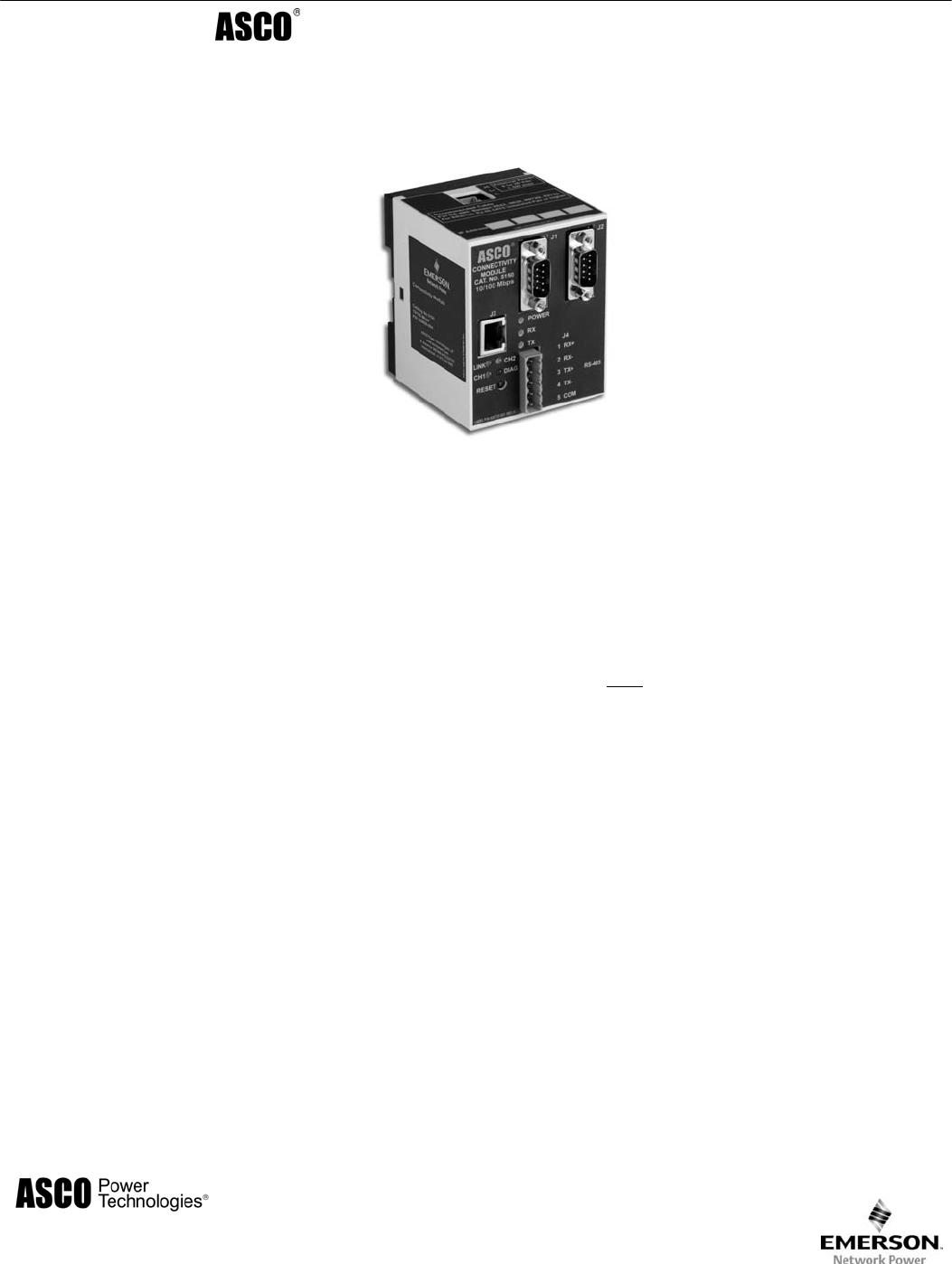
5100 Series, Catalog 5150
Connectivity Module
For use with Automatic Transfer Switches,
Power Manager, & Digital Power Meter
Section Page
Welcome............................................................................................................. ii
Overview, Specifications, Installation Overview, DIP Switch (RS485).............. iii
Outline and Mounting Drawing.......................................................................... iv
Interface Wiring Diagrams................................................................. v, vi, vii, viii
Status LEDs....................................................................................................... ix
1 Installation
Installation Overview, DIP switch (RS485)........................................................ iii
on Automatic Transfer Switches (7000, 4000, 300, 940/962)......................... 1-1
on stand-alone Power Manager, Test Communications .................................1-2
View & Change Configuration Pages, View Pages after Installation .............. 1-3
2 7000 & 4000 Series ATS (with & without a Power Manager or Power Meter)
Configurator Screens................................................................................2-1, 2-2
Detail Screen................................................................................................... 2-3
3 Series 300 ATS (with & without a Power Manager or Power Meter)
Configurator Screens................................................................................3-1, 3-2
Detail Screen................................................................................................... 3-3
4 ASCO 940 / 962 ATS (with & without a Power Manager)
Configurator Screen ........................................................................................ 4-1
Detail Screen................................................................................................... 4-2
5 Power Manager & Power Meter (stand-alone, generator, or circuit breaker)
Configurator Screen ........................................................................................ 5-1
Detail Screens ..........................................................................................5-2, 5-3
Appendix TCP/IP Installation & Configuration for Windows XP ® and Windows 7 ®.......A-1
Troubleshooting...............................................................................................A-3
Create & copy favorites folder, 3rd Party Modbus ® device configuration........A-4
Enabling SNMP Internet-standard protocol.....................................................A-5
Communication Address Forms ..........................................................in the back
Index ................................................................................................................back page
ii Welcome Connectivity Module
Windows and Internet Explorer are registered trademarks of Microsoft Corporation.
Who Should Use this Installation Manual
This manual for the Connectivity Module should be used to assist individuals who will:
• install the Connectivity Module (mount and wire)
• configure the Connectivity Module
• enter in information about your Automatic Transfer Switches
(7000 & 4000 Series, Series 300, ASCO 940,962,436,434,447,448)
• use Ethernet access to monitor Connectivity Module (connected devices)
Prerequisites A working knowledge of Windows XP ® and Windows Internet Explorer 6.0 or higher
(with Microsoft Virtual Machine or the latest version of the Java Runtime Environment
loaded) is necessary to configure the Connectivity Module.
Important information To properly set up the software, you will need the nameplate data and other
that you will need information from all your Automatic Transfer Switches including:
• ATS Name (your designation for the ATS)
• ATS Location (where the ATS is located in the building)
• Voltage Rating, Ampere Rating, and number of Poles for each ATS
• Catalog No. and Serial No. of each ATS
• Type of ATS (ATS or ATS/BP [ATS with bypass-isolation switch])
• Device Address (set in each ATS, Power Manager , or Digital Power Meter)
Product Manuals that you may need
7000 & 4000 Series ATS & Group 5 Controller 381333-126 & appropriate ATS manual
Series 300, ASCO 940, 962, 436, 434, 447, 448 ATS appropriate ATS manual
Power Manager Xp, Catalog 5220D, 5220T 381333-199
Digital Power Meter, Catalog 5210 381333-368
Serial Module, Catalog 5110 (Acc. 72A) 381333-240
ATS Remote Annunciator, Catalog 5310 (1 channel) 381333-316 & 381333-317
ATS Remote Annunciator, Catalog 5350 (8 channel) 381333-314 & 381333-315
Tip Ö Communication Address form is included at the back to help you fill in needed information on your
Connectivity Modules, ATSs, Power Managers, Digital Power Meters.
The Connectivity Module provides Ethernet-access that allows users to view data from ASCO automatic
transfer switches, Power Managers, and Digital Power Meters. All users must follow these precautions:
To avoid possible shock, burns, or death, deenergize all electrical
sources to the ATS before installing the Connectivity Module.
Be sure that Users to whom you give access are those persons that you want to
view information about the electrical system.
NOTIC
E
DANGER
!
ATS Remote Annunciator kits 8 channel K871966-004, 1 channel K871966-005
Kits include: ATS Remote Annunciator (RA), Connectivity Module (CM), power supply, mounting hardware, connecting cable
The CM can be configured to provide ATS data to ATS Remote Annunciators (RA) over Ethernet either on encryption disabled
or enabled mode. Details on how to configure all required parameters for the two modes are in the RA manuals listed above.
Encryption disabled mode is the default operation mode for both the CM and the RA. In this mode, the TCP port and protocol
assigned must be the same for both devices.
Encryption enabled mode is when both the CM and RA are configured for AES 128-bit encryption/decryption
communication. In this mode, the AES mode and AES port settings in the CM are enabled and assigned a value respectively.
Note that the AES port value must be different from the TCP port value (see screen on page 2-1).
Likewise, in the RA, encryption must be enabled and the TCP port is assigned with the same value as the AES port of the CM.
Note that the encryption works only on RAs with software version -003 or higher (refer to Configuration, Annunciator screen).
Connectivity Module Overview, Specifications, Installation Overview, DIP Switch iii
Modbus is a registered trademark of Gould Inc.
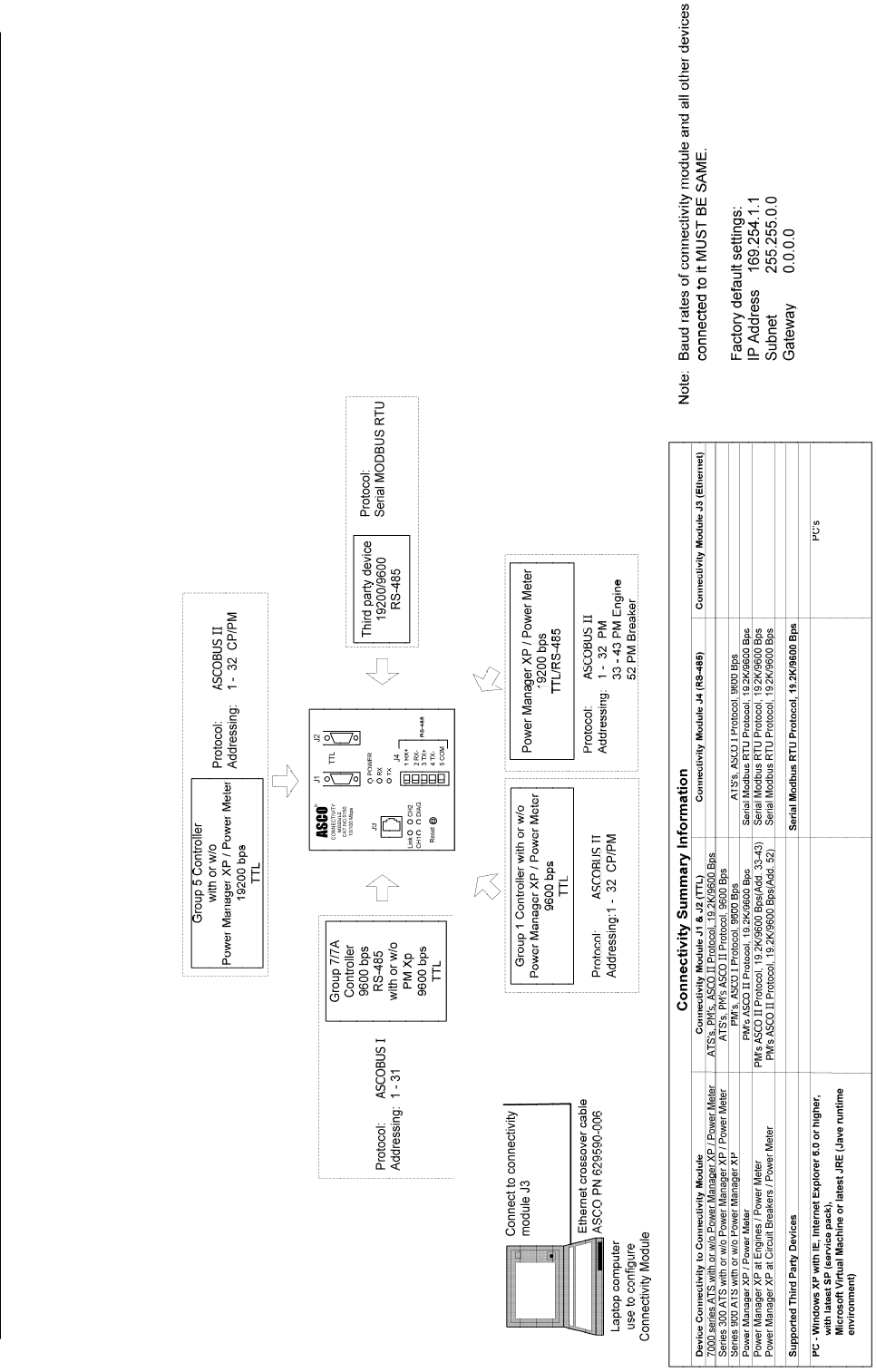
Overview
The Connectivity Module brings together several
different serial devices that communicate at different
baud rates and with different protocols to a common
Ethernet media. It can communicate with up to eight
clients, such as Web applications (web pages), Vpi, or
third-party Modbus ® devices simultaneously over
Ethernet media.
Specifications
Power Requirements: 24 V dc nominal (8 – 28 V dc)
1.5 Watt, UL Class 2 power supply, if needed.
Mounting: 35 mm DIN rail
Dimensions: 3.5” H, 2.8” W, 2.9” D (8.9 cm, 7.1 cm, 7.4 cm)
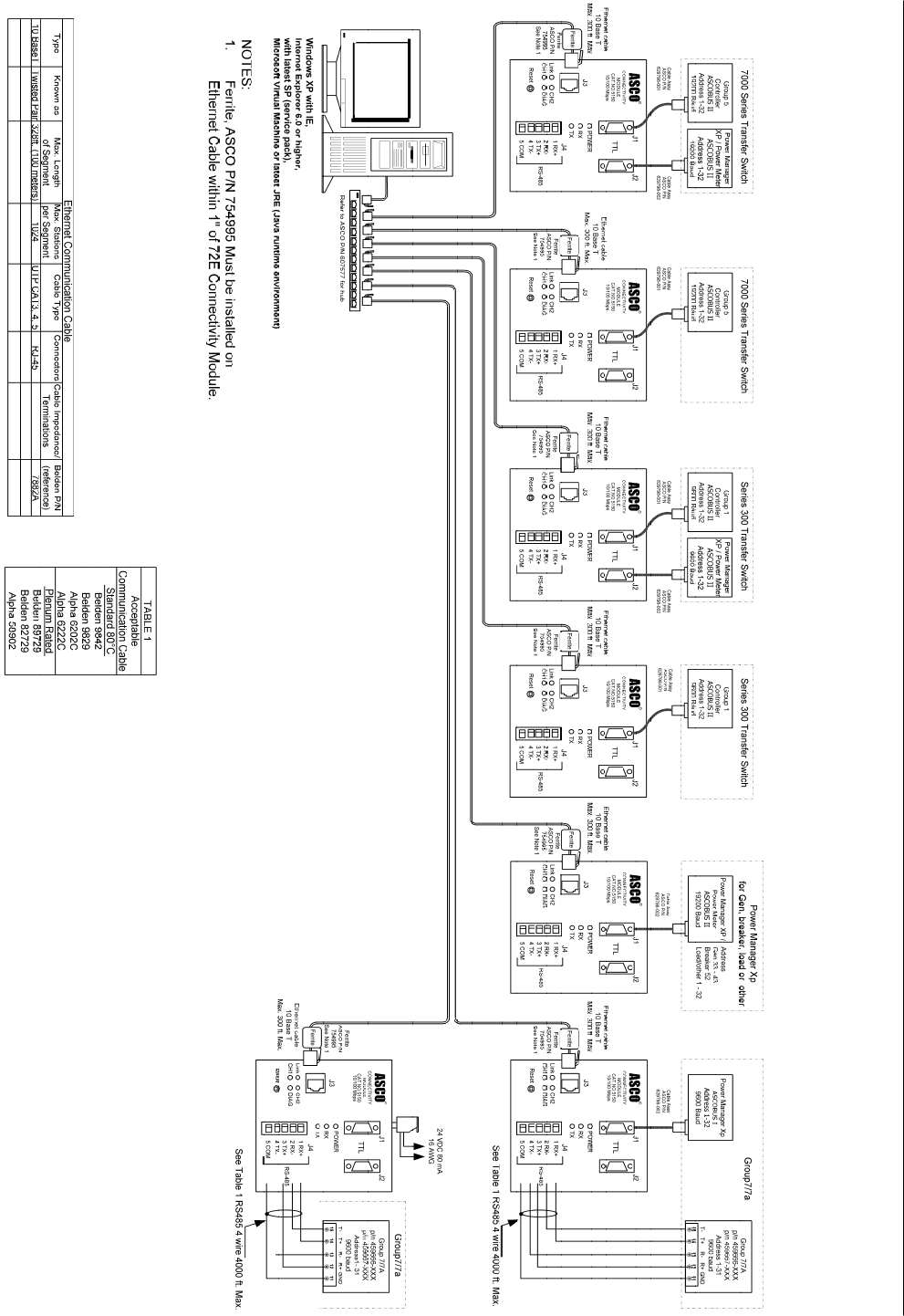
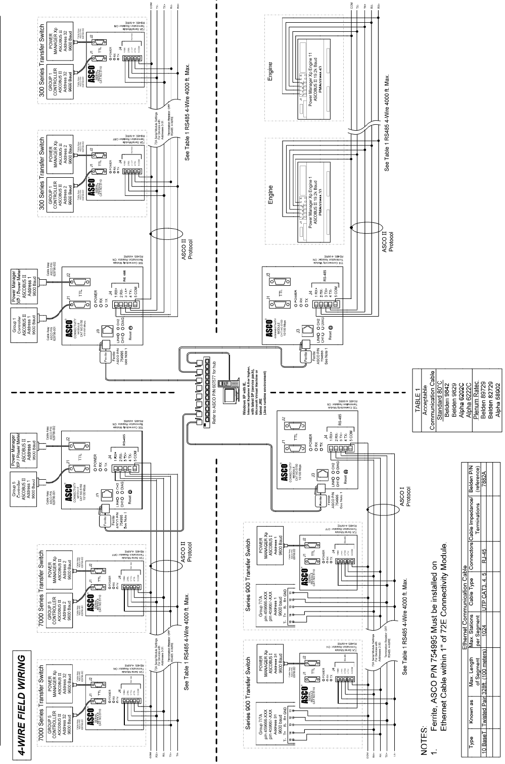
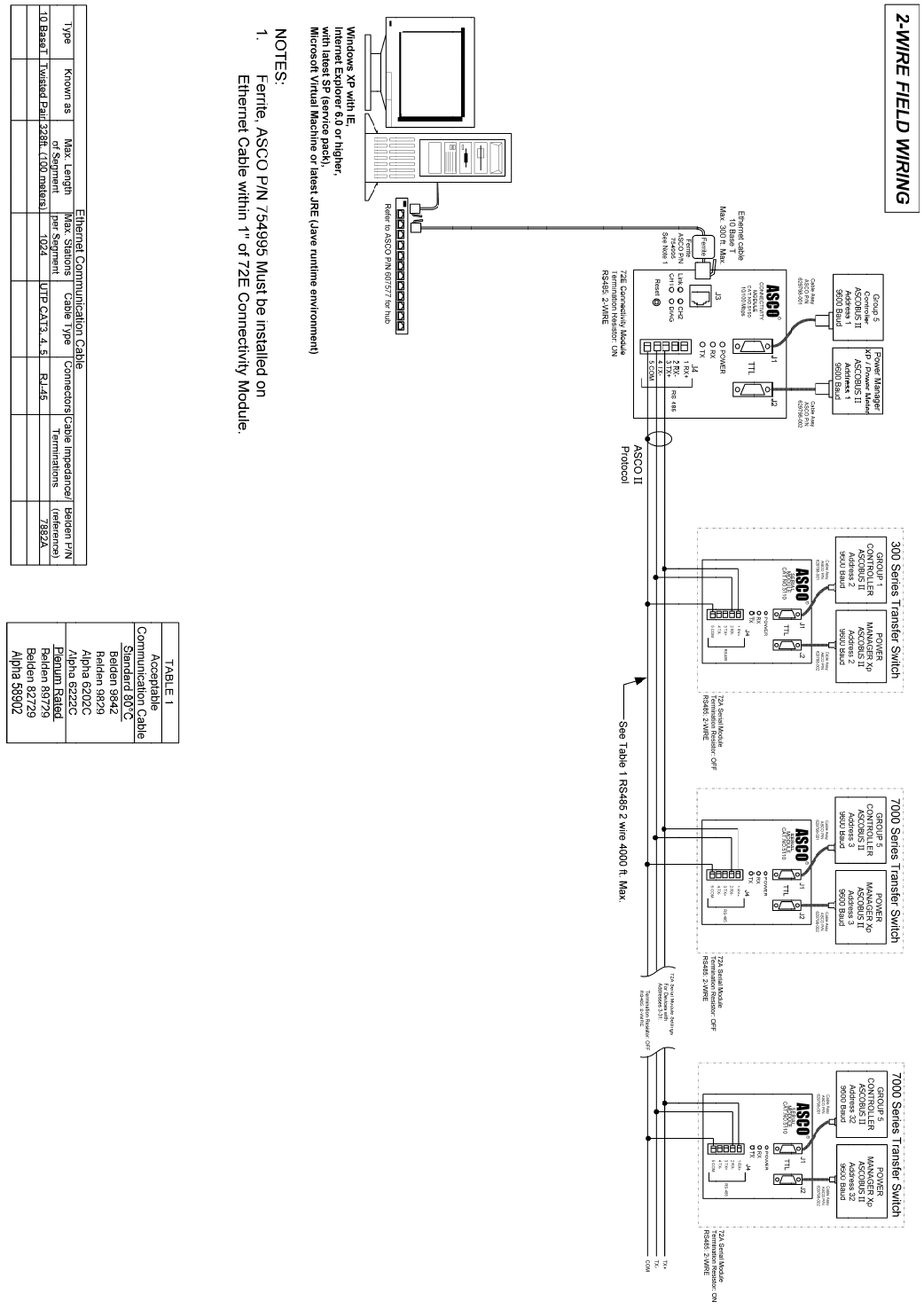
Field Communication Cable Requirements:
Ethernet: Belden 7882A or equiv. UTP CAT 5 with
RJ45 connectors (untwisted pair or higher)
Serial: Belden 9842, 9829, 89729, 82729 or Apha
6202C, 6222C, 58902. UL Listed, stranded,
twisted pairs, over-all foil shield with stranded drain wire
J1, J2 TTL Port Connectors: Two built-in TTL ports
(DB9 pin male) for ATS/PM connectivity
J3 Ethernet Port Connector :
One built-in 10 Base T (RJ45) 10 Mbps Ethernet port
J4 Serial RS-485 Port:
One 5-pin terminal block header with a socket block (J4)
designed to be daisy chained for up to 32 devices.
Terminal 1 – RX+ Terminal 4 – TX-
Terminal 2 – RX- Terminal 5 – Com
Terminal 3 – TX+
Ambient Temperature:
Operating 32 to 140° F (0 to 60° C)
Storage - -40 to 185° F (-40 to 85° C)
Configuration Parameters: The parameters that are required
to make an Ethernet connection are:
IP Address 169.254.1.1
Subnet Mask 255.255.0.0
Gateway 0.0.0.0
TCP Port No. 10001
The TCP port is used for passing the data to the applications
and is configurable for user specific requirement.
Baud Rates 19200 (default) or 9600
Flow Control No Flow Control (default)
Interface Mode TTL/RS485 – 4 wires (default)
Reply Timeout 200 milliseconds (default)
Protocol Support: The following protocols are supported:
Serial Protocol: ASCO I, II, and Modbus
Transport Protocol: TCP, UDP
Application Protocol: HTTP, Telnet, Modbus/TCP
AES Encryption enable or disable
Installation Overview
1. Determine the kind of network to use to connect the
various devices to the Connectivity Module.
2. If a RS485 network will be used, do not install the
Connectivity Module until the DIP switches are
checked and set on the bottom of the unit. See below.
3. Refer to the outline & mounting drawing (page iv)
and wiring diagrams (pages v, vi).
4. Select the appropriate installation (pages 1-1, 1-2)
that corresponds to the product to be connected.
5. Establish and test communications (page 1-2).
Refer to Status LEDs (page vii).
6. View and change configuration pages (page 1-3).
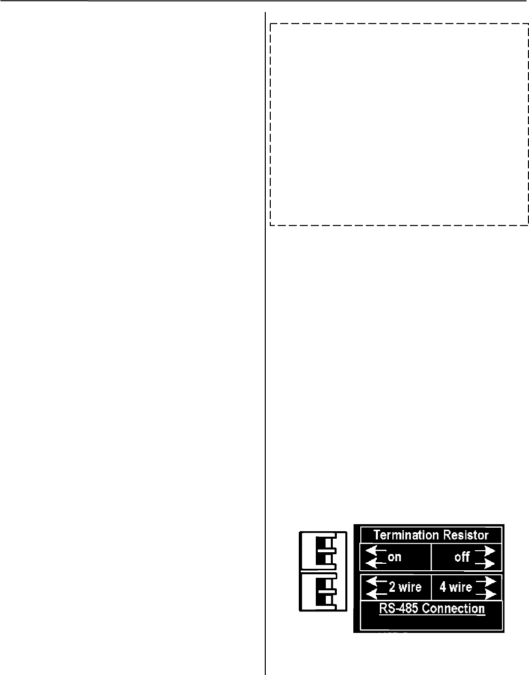
Check the DIP Switch Settings for RS485
For RS485 networks only, before installing the
Connectivity Module check the position of the DIP
switch actuators on the bottom of the unit. The upper two
actuators turn on a built-in termination resistor, if needed.
The lower two actuators select either a 2-wire or 4-wire
RS485 network. See the figure below.
Termination Resistor, upper two actuators
On a daisy chained RS485 network the Connectivity
Module termination resistor must be ON. Likewise only
the farthest device from the Connectivity Module must
have the termination resistor ON. All other devices must
be OFF. The DIP switch upper two actuators control the
built-in termination resistor:
ON – move to left. OFF – move to right.
2-Wire or 4-Wire network, lower two actuators
If a 2-wire RS485 network is to be attached to the
Connectivity Module, move the lower two actuators to
the left. If a 4-wire RS485 network is used, move these
actuators to the right.
DIP Switch on bottom of unit
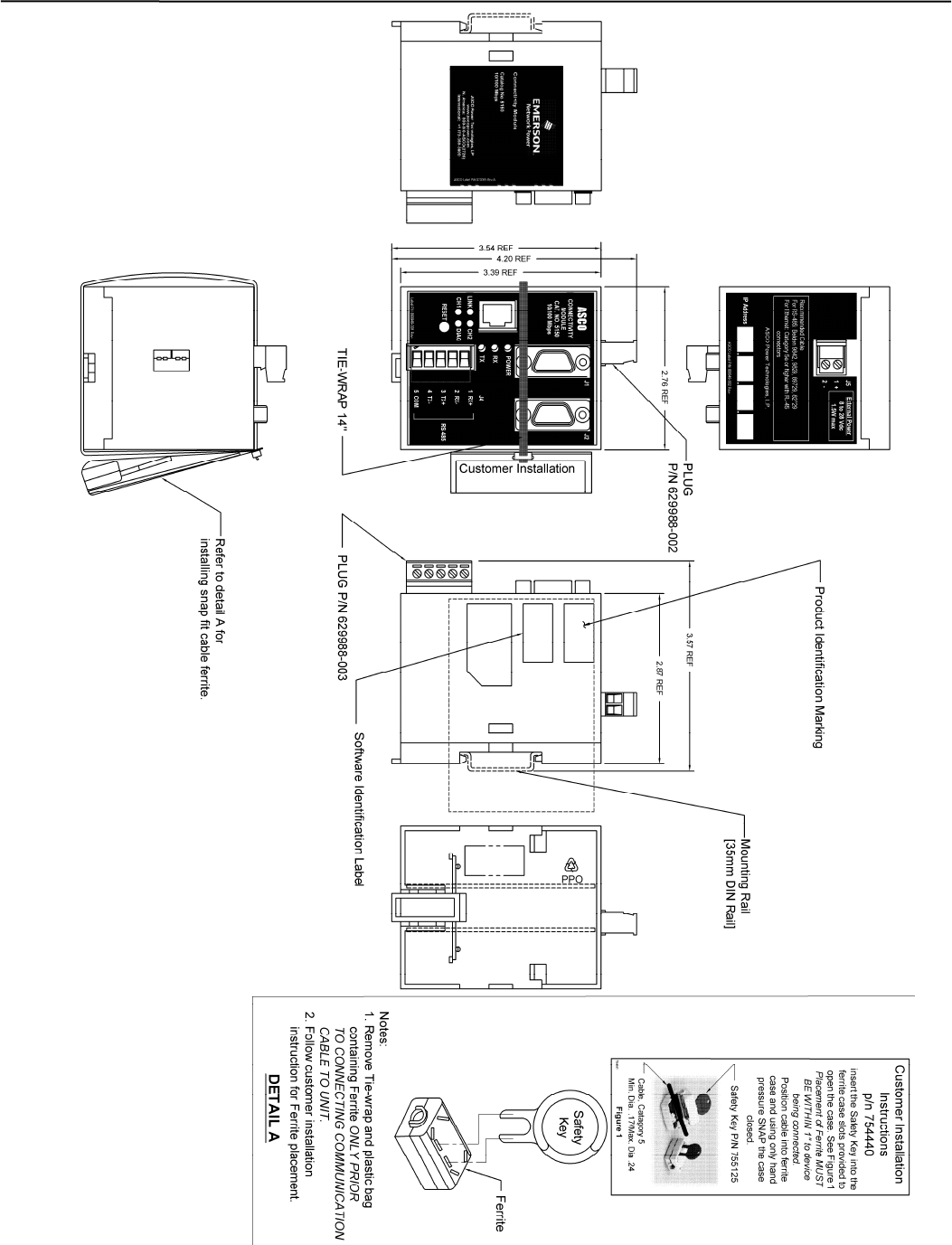
iv Outline and Mounting Drawing Connectivity Module
v Wiring Diagrams Connectivity Module
Connectivity Module Wiring Diagrams vi
vii Wiring Diagrams Connectivity Module
Connectivity Module Wiring Diagrams viii
Connectivity Module Status LEDs ix
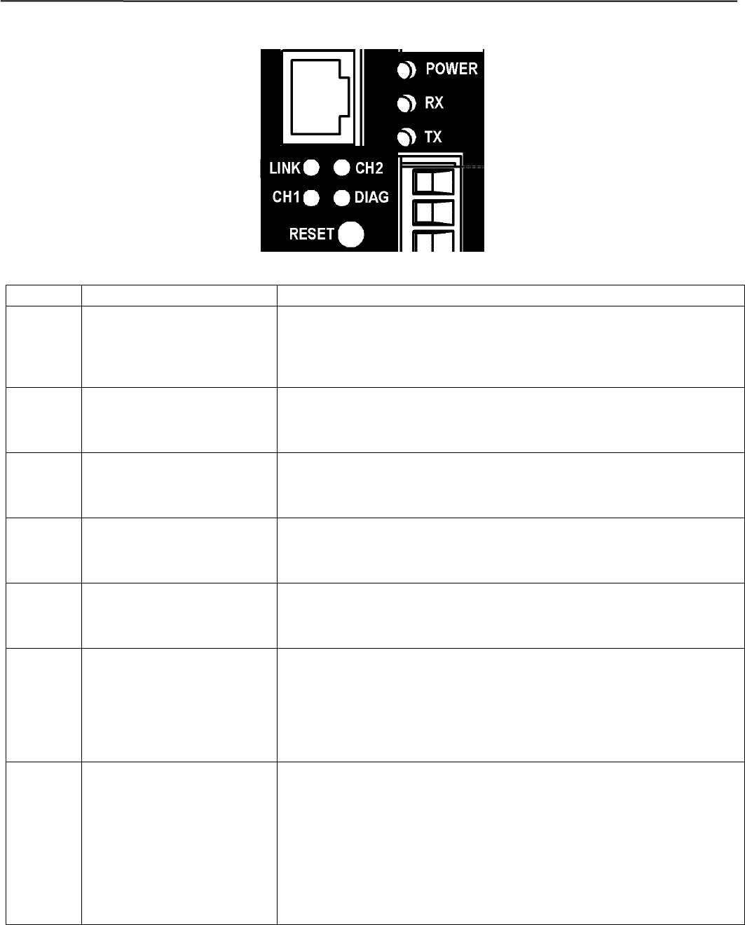
Status LEDs
LED LED Description LED Function / Mode of Operation
POWER Power indication status.
GREEN/AMBER
Solid GREEN – functioning as a Connectivity Module (Acc. 72E).
Solid AMBER – functioning as a Serial Module (Acc. 72A).
RX
Data receiving status.
GREEN
Blinking GREEN – indicates receiving data from a client.
TX
Data transmit status.
GREEN
Blinking GREEN – indicates transmitting data to a client.
LINK
Link status.
GREEN
Solid GREEN – indicates active Ethernet connection.
CH1
Client connection status.
GREEN
Blinking GREEN – indicates active Ethernet client connection.
CH2 Additional Diagnostic LED.
YELLOW
Blinking YELLOW then off – indicates server disconnection because of
Ethernet client inactivity.
Solid YELLOW then off – indicates server disconnection due to Ethernet
client disconnection.
DIAG Diagnostic.
RED
Off – indicates no error.
Short blinking RED then off – indicates active client/server write process.
Long blinking light then off – indicates server is receiving unrecognized
request packet from an Ethernet client.
Solid RED – indicates major error.
1-1 Installation Connectivity Module
How to Install the Connectivity Module
on 7000 & 4000 Series and Series 300 ATSs
The Connectivity Module (CM) mounts on a DIN rail
under the ATS Controller (Group 5 & 1). A short serial
cable connects the CM to the Controller. If a Power
Manager (PM) or Digital Power Meter (DPM) is present,
a long serial cable connects the CM to the PM. Refer to
installation drawings provided and follow the steps below
to install the Connectivity Module.
Connectivity Module Kit
K889950
for 7000 & 4000 Series
and Series 300 only
Connectivity Module Kit
K889950-001 for
7000 & 4000 Series
and Series 300
with PM or DPM
Connectivity
Module 5150 629800-004 Connectivity
Module 5150 629800-004
DIN Rail and
Hardware 754607 DIN Rail and
Hardware 754607
10-in. Serial
Cable for
Controller 629798-001 10-in. Serial
Cable for
Controller 629798-001
4-ft Serial
Cable for
PM or DPM * 629798-002
* A 9-foot serial cable (629798-004) is
required for G7ATB, G7ACTB, G7ADTB.
To avoid possible shock, burns, or death, deenergize all
electrical sources to the ATS before installing the
Connectivity Module.
1. De-energize both Normal and Emergency sources
that feed the ATS. Open enclosure door and check
with a non-contact AC voltage detector.
2. Mount the DIN rail (supplied in the kit) onto two
studs (on the door) below the Controller.
Connectivity Module will mount on the right side.
3. Install Connectivity Module onto DIN rail by
hooking the bottom of module on bottom of DIN rail
and rocking it upward unit it snaps in place.
4. Install the 10-inch serial cable between the Controller
receptacle (J7 on Group 5, J4 on Group 1) and the
Connectivity Module J1 receptacle.
5. If a PM (or DPM) is present, connect the 4-foot serial
cable between the PM J5 receptacle (or DPM J2
receptacle) and the Connectivity Module J2
receptacle.*
Now test communications (go to page 1-2).
How to Install the Connectivity Module
on ASCO 940/962 ATSs
The Connectivity Module (CM) mounts on a DIN rail
near the ATS Control Panel. A separate power supply is
needed unless it is connected to a Power Manager (PM).
Group 6A/7A Control Panel must have a Serial
Communication Kit added. A single communication
cable (2 twisted pairs and overall shield connects the CM
to the Control Panel). Refer to installation drawings
provided and follow the steps below to install the
Connectivity Module.
Connectivity Module Kit
K889953
for ASCO 940/962 only
Connectivity Module Kit
K889953-001
for ASCO 940/962 with PM
Connectivity
Module 5150 629800-004 Connectivity
Module 5150 629800-004
DIN Rail and
Hardware 754610 DIN Rail and
Hardware 754610
Serial Com.
Kit for Group
6A/7A CP * 467508 Serial Com.
Kit for Group
6A/7A CP * 467508
Serial Cable
for PM 629798-002
* Serial communication & transient protection boards.
Required
Power Supply **
not supplied
Communication Cable
(4 wires and an overall shield)
not supplied
24 Vdc, 80 mA ** use
16 AWG wire Belden 9842, 9829, 89729, 82729 or
Alpha 6202C, 6222C, 58902 only
** If a Power Manager (PM) is present, a power supply is not needed for
the Connectivity Module (CM). The serial cable from the PM provides
the power to the CM.
To avoid possible shock, burns, or death, deenergize all
electrical sources to the ATS before installing the
Connectivity Module.
1. De-energize both Normal and Emergency sources
that feed the ATS. Open enclosure door and check
with a non-contact AC voltage detector.
2. Mount DIN rail (supplied in the kit) onto two studs
(on the door) below or adjacent to the Control Panel.
3. Install the Connectivity Module onto DIN rail.
4. Prepare and connect the specified communication
cable between the Control Panel terminals and the
Connectivity Module J4 terminals as listed below:
5. Prepare and connect the 24 Vdc power supply to the
Connectivity Module. Use 16 AWG wiring to J5
terminal plug (1 is + positive, 2 is – negative).
Now test communications (go to page 1-2).
DANGER
!
DANGER
!
Connectivity Module Installation 1-2
How to Install the Connectivity Module for
a stand-alone Power Manager or Digital
Power Meter
The Connectivity Module (CM) mounts on a DIN rail
near the Power Manager (PM) or Digital Power Meter
(DPM). A long serial cable connects the Connectivity
Module to the PM or DPM. Refer to installation drawings
provided and follow the steps below to install the
Connectivity Module.
Connectivity Module Kit K889958
for a stand-alone Power Manager or Digital
Power Meter (not connected to an ATS)
Connectivity
Module 5150 629800-004
DIN Rail and
Hardware 754610
4 ft. Serial Cable
for PM or DPM 629798-002
To avoid possible shock, burns, or death, deenergize all
electrical sources to the ATS before installing the
Connectivity Module.
1. De-energize the power source that feeds the PM (or
DPM). Open enclosure door and check with a
non-contact AC voltage detector.
2. Mount the DIN rail (supplied in the kit) onto two
studs (on the door) below or adjacent to the PM or
DPM.
3. Install Connectivity Module onto DIN rail by
hooking the bottom of module on bottom of DIN rail
and rocking it upward unit it snaps in place.
4. Install the 4-foot serial cable between the Power
Manager J5 receptacle (or Digital Power Meter J2
receptacle) and the Connectivity Module J2
receptacle.
Now test communications (go to next column).
How to Test Communication to the
Connectivity Module
You need the following settings from your network
administrator for each Connectivity Module (CM)
connected to an Automatic Transfer Switch (ATS), Power
Manager (PM), or Digital Power Meter (DPM). Fill in the
form provided in the Appendix:
IP Address: ______________ (unique for each module)
Subnet mask __________ (usually same for all modules)
Gateway: ________________________ (usually blank)
Required items:
• Portable laptop computer with network card, running
Windows Xp and Windows Internet Explorer 6.0 +
installed.
• Ethernet crossover network cable (part no.
629590-006).
• Connectivity Module connected to the ATS, PM, or
DPM.
1. Directly connect the specified Ethernet crossover
cable between your laptop’s Ethernet jack and the
deenergized Connectivity Module jack J3.
2. For safety, close the ATS, PM, or DPM enclosure
door as far as possible (with the crossover cable
running to the laptop computer outside the enclosure).
Then energize ATS, PM, or DPM and the
Connectivity Module.
3. Refer to the Appendix and select the appropriate
TCP/IP Installation & Configuration instructions for
your laptop computer’s operating system. This
procedure sets up your laptop computer (if necessary)
for network connections and tests communications to
the Connectivity Module.
4. After you have confirmed communication with the
Connectivity Module, continue to the next page to
view and change the configuration of the
Connectivity Module and ATS, PM, or DPM.
Now view and change the configuration
(go to page 1-3)
DANGER
!
1-3 Installation Connectivity Module
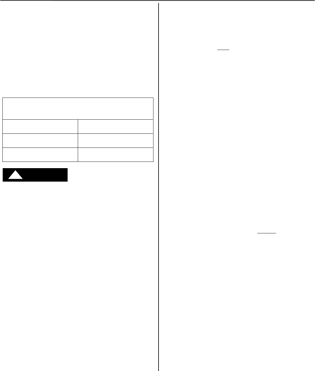
How to View & Change Configuration Pages
from a Connectivity Module
To view and change configuration pages on a client
computer, follow these steps:
1. Be sure that your computer is connected to the Internet.
2. Start Microsoft Internet Explorer browser on computer.
3. In the address bar, type in the address of the Connectivity
Module, add /config.htm, press Enter :
http://169.254.1.1/config.htm
PASSWORD
On the Login screen there is
no password until you enter
one. If you click Login
without entering a password,
there is no protection. If you
want protection, click
Change Password; the
Change Password screen
appears. Then enter a
password (15 char. max.) in
New Password, enter it again
in Confirm New Password,
and click OK. You can set
only one password.
The Connectivity Module sends HTML files to the client
computer. Internet Explorer interprets these HTML files,
formats them, and displays the pages to the user.
Pages 2-1, 2-2, 3-1, 3-2, 4-1, 5-1 show Device Configurator
screens for ATSs and PMs or DPMs (go to the appropriate
section for the specific ATS, PM, or DPM).
Tip
You can add the address to your Favorites for convenient
access to multiple Connectivity Modules; follow these steps:
1. Click Favorites, then click Add to Favorites, click New
Folder, then type the Folder name (ATS Configuration,
for example), and click OK.
2. To rename the address, highlight it, and type the new name,
and click OK.
When you are finished viewing pages, close Internet Explorer.
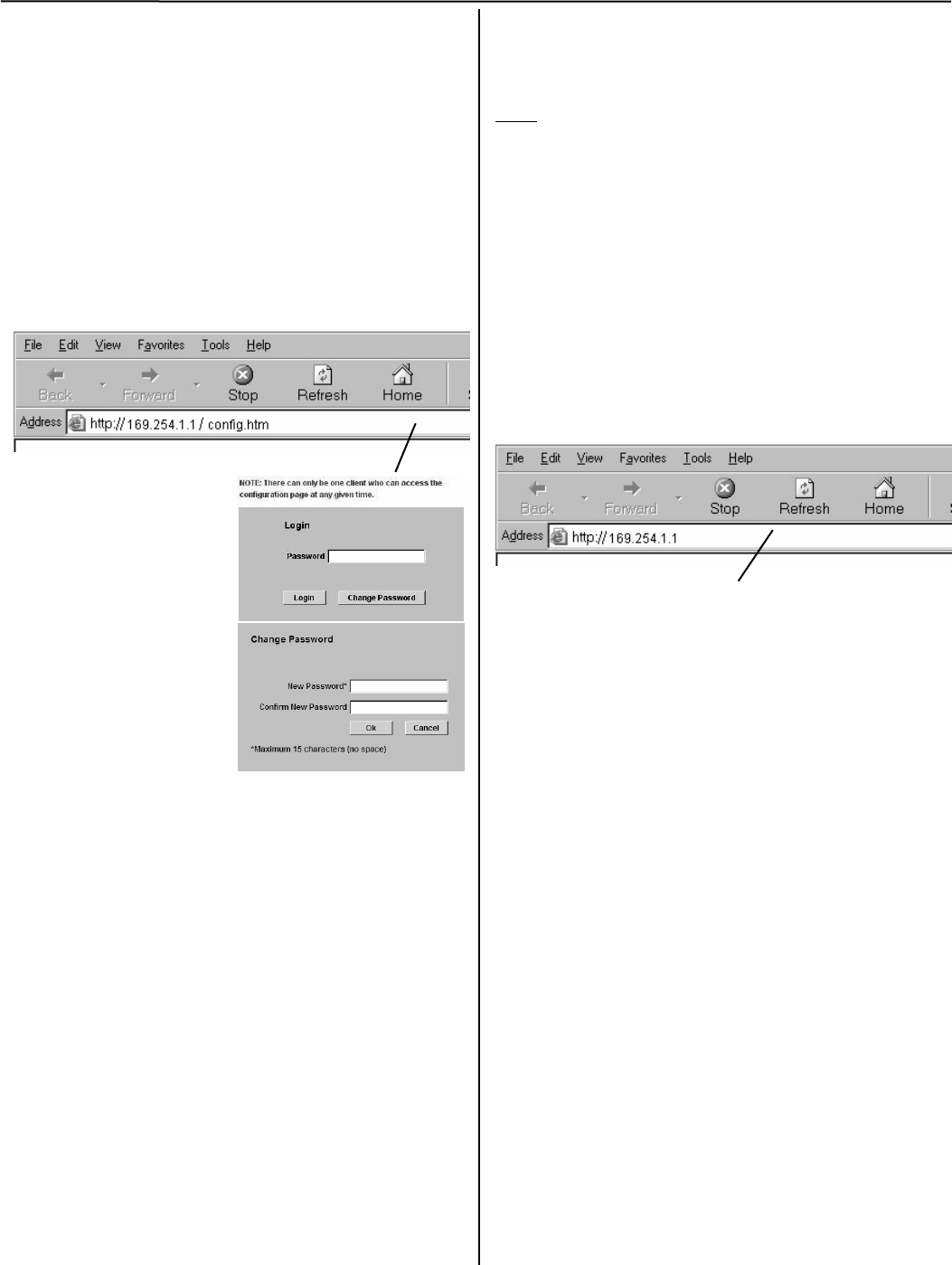
How to View Pages from a Connectivity
Module after it is installed
After installation, testing, and configuration is completed,
to view pages on a client computer, follow these steps:
1. Be sure that your computer is connected to the
Internet.
2. Start Microsoft Internet Explorer browser on the
computer.
3. In the address bar, type in the address of the
Connectivity Module:
http://169.254.1.1
The Connectivity Module sends HTML files to the client
computer. Internet Explorer interprets these HTML files,
formats them, and displays the pages to the user.
Pages 2-3, 3-3, 4-2, 5-2, 5-3 show typical HTML pages
(Detail screens) for ATSs and PMs or DPMs (go to the
appropriate section for the specific ATS, PM, or DPM).
Tip
You can add the address to your Favorites for
convenient access to multiple Connectivity Modules;
follow these steps:
1. Click Favorites, then click Add to Favorites,
click New Folder, then type the Folder name
(ATSs, for example), and click OK.
2. To rename the address, highlight it, and type the
new name, and click OK.
3. When you are finished viewing pages, close
Internet Explorer.
Type the address of the Connectivity Module and add
/config.htm here.
Type the address of the
Connectivity Module here
Connectivity Module 7000 & 4000 Series ATSs 2-1
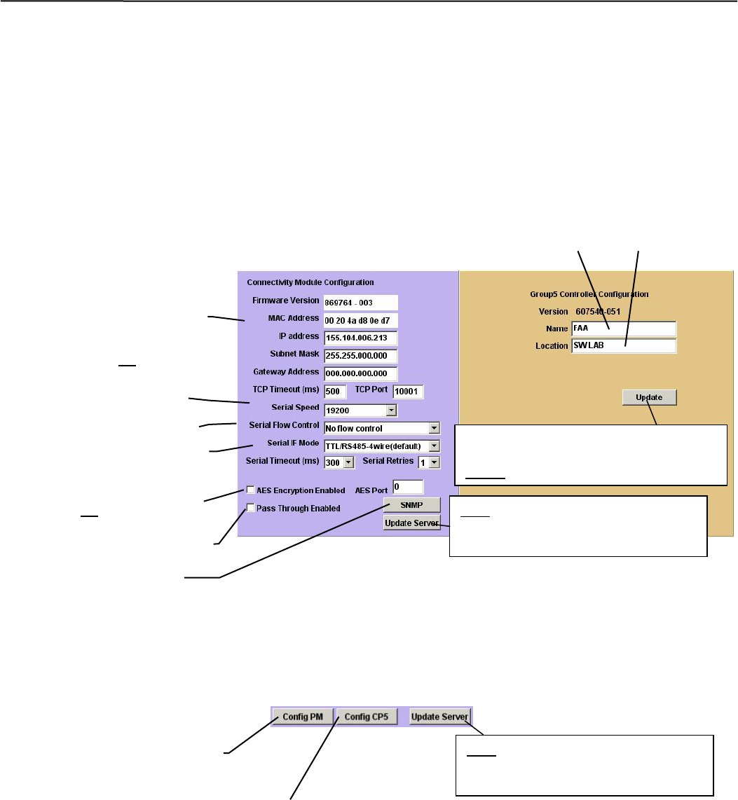
Device Configurator Screen for 7000 & 4000 Series ATSs
The Device Configurator Screen for 7000 & 4000 Series ATSs shows the Group 5 controller configuration
settings (right side) and Connectivity Module (server) configuration settings (left side) for the selected ATS.
Group 5 Controller Configuration (right side)
Enter or change the ATS Name (8 char. max.)and the ATS Location (20 char. max.). Press the Update
button when finished to save the controller configuration changes.
Connectivity Module (server) Configuration (left side)
Several configuration settings must be set appropriately as described below. Press the Update Server button
when finished to save configuration changes.
Device Configurator Screen for 7000 & 4000 Series ATSs
When a Power Manager or Digital Power Meter is connected, additional buttons appear at the bottom of the
Connectivity Module Device Configuration screen.
Additional Buttons on Device Configurator Screen for
7000 & 4000 Series ATSs with Power Manager or Digital Power Meter
A
TS Location
A
TS Name
Serial Port Speed 19200
Consult with your network
administrator for these 4 settings:
IP Address
Subnet Mask
Gateway Address
TCP Port Number
(Range of ports allowed is:
10024-65535, but do not use
ports 14000-14009 or 30718)
Press Update button when finished to
save the configuration changes. Do this
before you press Update Server button.
After Controller has been updated,
press Update Server button to save
the configuration changes.
Flow Control No flow control
Interface Mode RS485-4 or 2 Wire
Press to configure the Power
Manager or Digital Power Meter.
Press to configure the Group 5 Controller.
3r
d
party device running own protocols
Encyrption enable check box and
assign an AES port (same range as
TCP port but do not use the same
port number used for TCP port.)
After Controller, PM, or DPM has
been updated, press Update Server
button to save the configuration
SNMP refer to A
pp
endix A-5
2-2 7000 & 4000 Series ATSs Connectivity Module
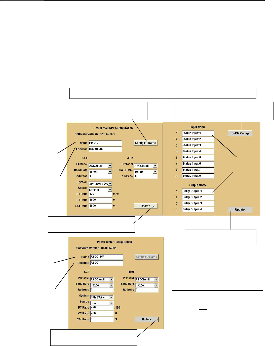
Device Configurator Screen for 7000 & 4000 Series ATSs with a PM or DPM
If a Power Manager (PM) or Digital Power Meter (DPM) is used with a 7000 & 4000 Series ATS, a button appears
on the lower left corner of the Connectivity Module Device Configurator screen. Press the Config PM button to
display the Power Manager or Power Meter Configuration screen (right side).
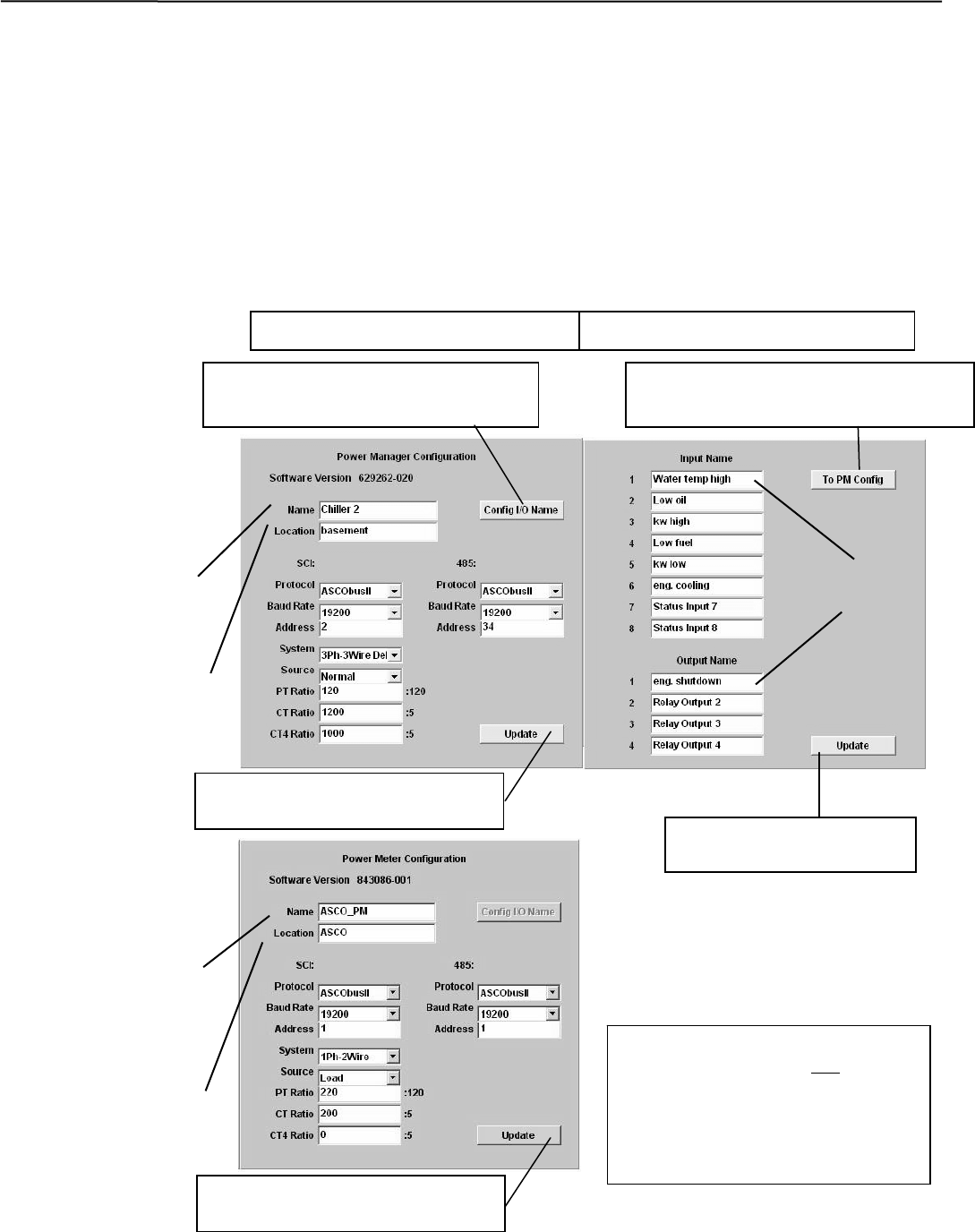
Power Manager or Power Meter Configuration
Enter or change the PM or DPM Name (8 char. max.) and Location (20 char. max.). Several configuration settings
must be set appropriately. Press the Update button when finished to save the PM or DPM configuration changes.
Input Name & Output Names (Power Manager only)
For a Power Manager, press the Config I/O Name button to display the Input Name and Output Name screen.
Enter or change the names (16 char. max.) of the inputs and outputs. Press the Update button when finished to save.
Input names
Input & Output Names (PM only) PM or DPM Configuration
Press Update button when
finished to save the names.
Press Update button when
finished to save the configuration
Press Config I/O Name button to
display Input & Output Names screen. Press To PM Config button to return to
Power Manager Configuration screen.
Output names
Power Manager
name
Power Manager
location
NOTE
Update the PM, DPM, or Group 5
Controller first if you need to update
the server. Do not close the browser
during the updating process. The
PM, DPM, or CP update request will
be discarded if the browser is closed.
Power Manager
Power Meter
Power Meter
name
Power Meter
location
Press Update button when
finished to save the configuration
Connectivity Module 7000 & 4000 Series ATSs 2-3
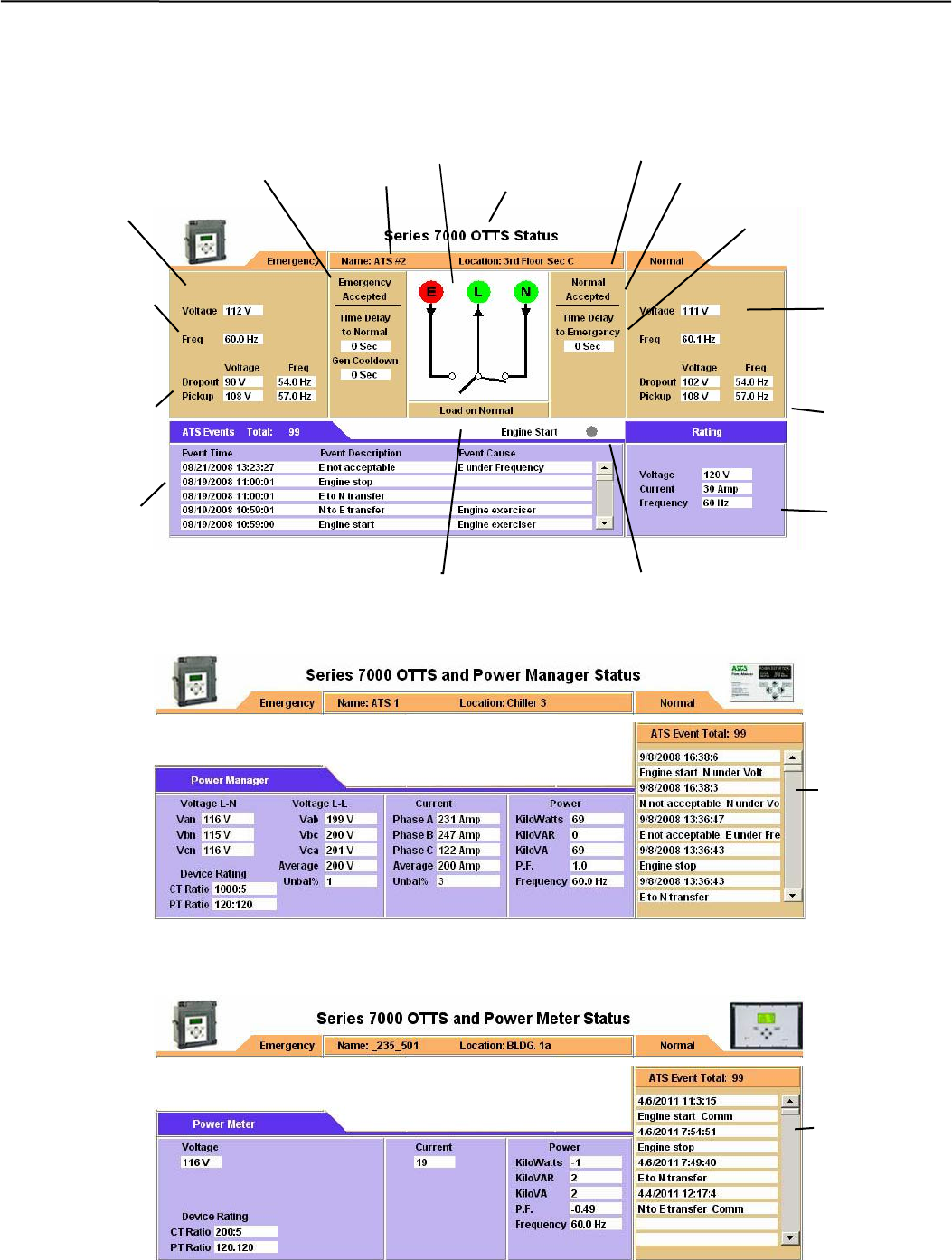
Detail Screen for 7000 & 4000 Series ATSs
The Detail Screen for 7000 & 4000 Series ATSs shows the switch location, ratings, timer settings, actual
timer values, pickup and dropout settings, event logging, and other status indications.
Detail Screen for 7000 & 4000 Series ATSs with a Power Manager
Same as above and adds information from the Power Manager (voltage current, power, and rating).
Detail Screen for 7000 & 4000 Series ATSs with a Digital Power Meter
Same as above and adds information from the Power Meter (voltage current, power, and rating).
Actual voltage
& frequency
readings from
ATS controller.
Load connected to Normal or Emergency Source
ATS events
(date & time,
Description,
and cause)
A
TS ratin
g
s
Engine start signal (red means active)
ATS location
ATS name
Voltage &
frequency
settings in ATS
controller.
Status of
Emergency
Source
Actual voltage
& frequency
readings from
ATS controller.
Voltage &
frequency
settings in ATS
controller.
ATS type
Active time delays
Active time delays
Status of Normal Source
ATS one-line icon shows position & source status (green or red circle
means source is acce
p
table
,
g
re
y
circle means source is not acce
p
table
)
A
TS events
on right
side of
screen
A
TS events
on right
side of
screen
3-1 Series 300 ATSs Connectivity Module
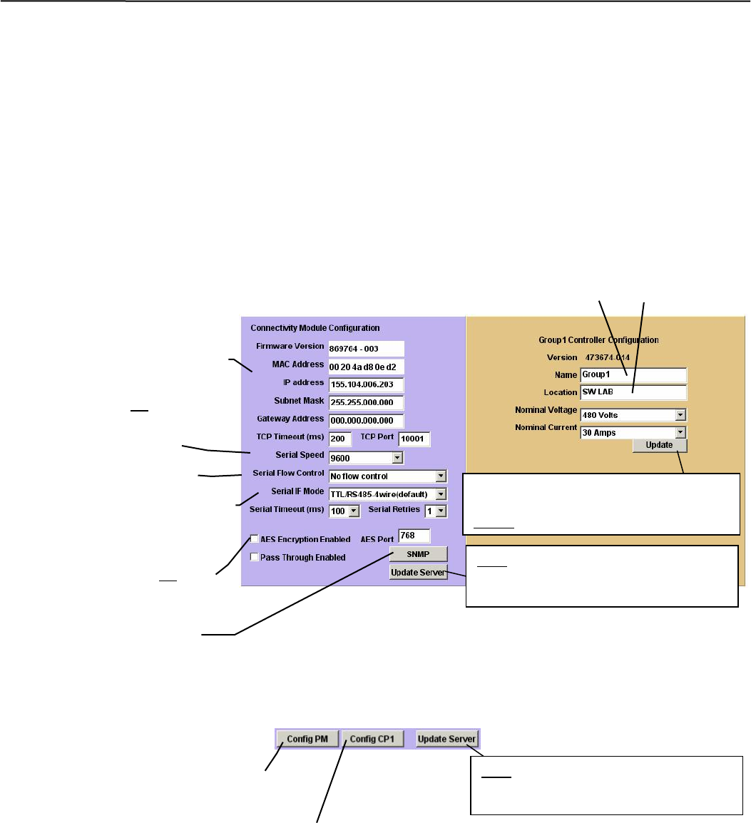
Device Configurator Screen for Series 300 ATSs
The Device Configurator Screen for Series 300 ATSs shows the Group 1 controller
configuration settings (right side) and the Connectivity Module (server) configuration
settings (left side) for the selected ATS.
Group 1 Controller Configuration (right side)
Enter or change the ATS Name (8 char. max.) and the ATS Location (20 char. max.). Press
the Update button when finished to save the Group 1 controller configuration changes.
Connectivity Module (server) Configuration (left side)
Several configuration settings must be set appropriately as described below. Press the Update
Server button when finished to save configuration changes.
Device Configurator Screen for Series 300 ATSs
When a Power Manager or Digital Power Meter is connected, additional buttons appear at the bottom of the
Connectivity Module Device Configuration screen.
Additional Buttons on Device Configurator Screen for
Series 300 ATSs with Power Manager or Digital Power Meter
ATS Location
ATS Name
Serial Port Speed 9600
Consult with your network
administrator for these 4 settings:
IP Address
Subnet Mask
Gateway Address
TCP Port Number
(Range of ports allowed is:
1024-65535, but do not use
ports 14000-14009 or 30718)
Press Update button when finished to
save the configuration changes. Do this
before you press Update Server button.
After Controller or has been updated,
press Update Server button to save
the configuration changes.
Flow Control No flow control
Interface Mode RS485-4 or 2 Wire
Encyrption enable check box
and assign an AES port (same
range as TCP port but do not use
the same port number used for
TCP port.)
Press to configure the Power
Manager or Digital Power Meter.
Press to configure the Group 1 Controller.
After Controller, PM, or DPM has been
updated, press Update Server button
to save the confi
g
uration chan
g
es.
SNMP refer to A
pp
endix A-5
Connectity Module Series 300 ATSs 3-2
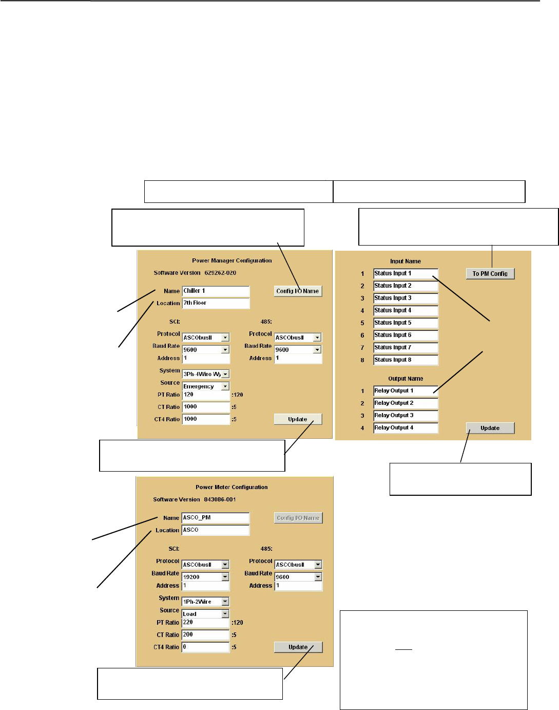
Device Configurator Screen for Series 300 ATSs with a PM or DPM
If a Power Manager (PM) or a Digital Power Meter (DPM) is used with a Series 300 ATS, a button appears on the
lower left corner of the Connectivity Module Device Configurator screen. Press the Config PM button to display
the Power Manager or Power Meter Configuration screen (right side).
Power Manager or Power Meter Configuration
Enter or change the PM or DPM Name (8 char. max.) and Location (20 char. max.). Several configuration settings
must be set appropriately. Press the Update button when finished to save the PM or DPM configuration changes.
Input Name & Output Names (Power Manager only)
For a Power Manager, press the Config I/O Name button to display the Input Name and Output Name screen.
Enter or change the names (16 char. max.) of the inputs and outputs. Press the Update button when finished to save.
Input names
Input & Output Names (PM only) PM or DPM Configuration
Press Update button when
finished to save the names.
Press Update button when finished
to save the confi
g
uration chan
g
es.
Press Config I/O Name button to
display Input & Output Names screen.
Press To PM Config button to return to
Power Manager Configuration screen.
Output names
Power Manager
name
Power Manager
location
NOTE
Update the PM, DPM, or Group 1
Controller first if you need to update
the server. Do not close the browser
during the updating process. The PM,
DPM, or CP update request will be
discarded if the browser is closed.
Power Manager
Power Meter
Power Meter
name
Power Meter
location
Press Update button when finished
to save the confi
g
uration chan
g
es.
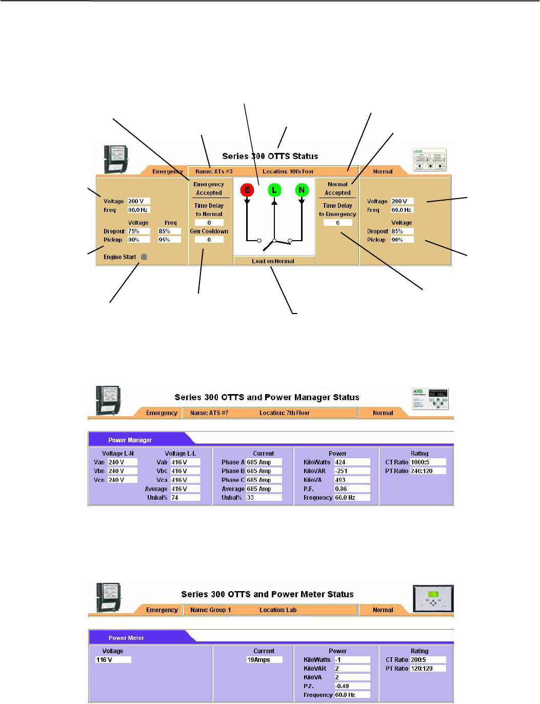
3-3 Series 300 ATSs Connectivity Module
Detail Screen for Series 300 ATSs
The Detail Screen for Series 300 ATSs shows the switch location, ratings, timer
settings, actual timer values, pickup and dropout settings, and other status indications.
Detail Screen for Series 300 ATSs with a Power Manager
The Detail Screen for Series 300 ATSs with a Power Manager is the same as above
and adds information from the PM (voltage, current, power, and rating).
Detail Screen for Series 300 ATSs with a Digital Power Meter
The Detail Screen for Series 300 ATSs with a Digital Power Meter is the same as
above and adds information from the DPM (voltage, current, power, and rating).
Actual voltage
reading from
A
TS controller.
Load connected to Normal or Emergency Source
Engine start signal
(red means active)
ATS location
Status of Normal SourceATS name
Voltage &
frequency
settings in ATS
controller.
Status of
Emergency Source
Actual voltage
& frequency
readings from
ATS controller.
Voltage &
frequency
settings in ATS
controller.
ATS type
Active
time dela
y
s Active time delays
ATS one-line icon shows position & source status (green or red circle
means source is acceptable, grey circle means source is not acceptable)
Connectivity Module ASCO 940/962 ATSs 4-1
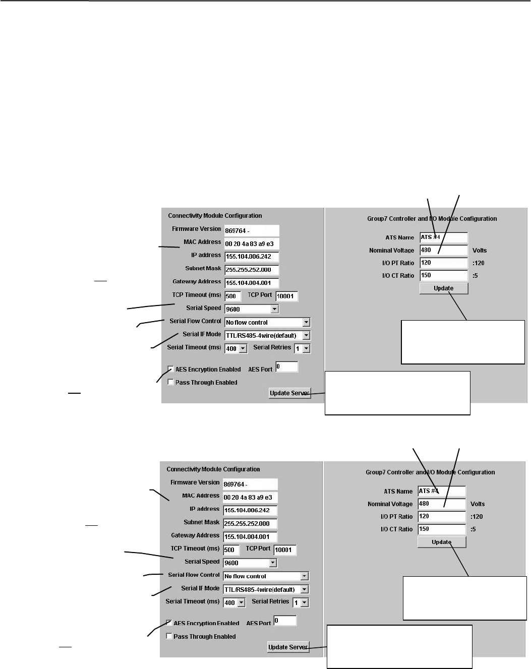
Device Configurator Screen for ASCO 940/962 ATSs
The Device Configurator Screen for ASCO 940/962 ATSs shows the Group 7A controller configuration
settings (right side) and the Connectivity Module (server) configuration settings (left) for the selected ATS.
Group 7A Controller Configuration (right side)
Enter or change the ATS Name (18 char. max.) and ATS Nominal Voltage (must be entered to get correct
reading). Press the Update button when finished to save the Group 7A controller configuration changes.
Connectivity Module (server) Configuration (left side)
Several configuration settings must be set appropriately as described below. Press the Update Server button
when finished to save configuration changes.
Device Configurator Screen without Power Manager
Device Configurator Screen with Power Manager
Nom. Volta
g
eATS Name
Serial Port Speed 9600
Consult with your network
administrator for these 4 settings:
IP Address
Subnet Mask
Gateway Address
TCP Port Number
(Range of ports allowed is:
10024-65535, but do not use
ports 1400-14009 or 30718)
Press Update button
when finished to save
the configuration
Press Update Server button
when finished to save the
configuration changes.
Flow Control No flow control
Interface Mode RS485-4 or 2 Wire
Nom. Volta
g
e
A
TS Name
Serial Port S
p
eed 9600
Consult with your network
administrator for these 4 settings:
IP Address
Subnet Mask
Gateway Address
TCP Port Number
(Range of ports allowed is:
10024-65535, but do not use
ports 1400-14009 or 30718)
Press Update button
when finished to save
the configuration
Press Update Server button
when finished to save the
configuration changes.
Flow Control No flow control
Interface Mode RS422/485-4Wire
Encyrption enable check box and
assign an AES port (same range as
TCP port but do not use the same
port number used for TCP port.)
Encyrption enable check box and
assign an AES port (same range as
TCP port but do not use the same
port number used for TCP port.)
xxx
xxx
4-2 ASCO 940/962 ATSs Connectivity Module
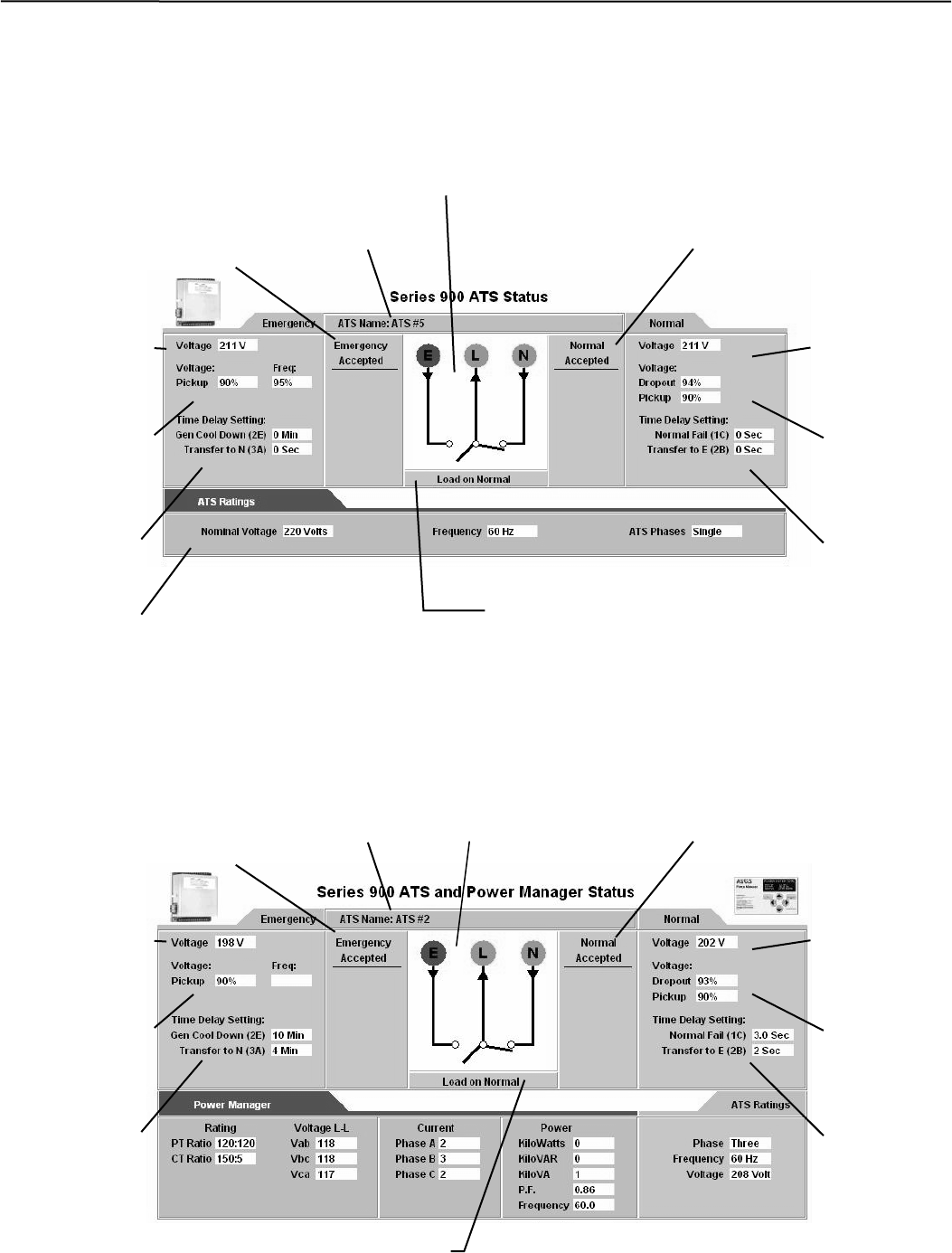
Detail Screen for ASCO 940/962 ATSs
The Detail Screen for ASCO 940/962 ATSs shows the switch location,
ratings, timer settings, actual timer values, pickup and dropout settings, and
other status indications.
Detail Screen for ASCO 940/962 ATSs with a Power Manager
The Detail Screen for ASCO 940/962 ATSs shows the switch location,
ratings, timer settings, actual timer values, pickup and dropout settings, and
other status indications.
Actual voltage
reading from
A
TS controller.
Load connected to Normal or Emer
g
enc
y
Source
A
TS ratin
g
s
Status of Normal SourceATS name
Voltage &
frequency
settings in ATS
controller.
Status of
Emergency
Source
Actual voltage
reading from
ATS controller.
Voltage &
frequency
settings in ATS
controller.
ATS one-line icon shows position & source status
(green or red circle means source is acceptable,
grey circle means source is not acceptable)
Time delay
settings in
ATS
controller.
Time delay
settings in
ATS
controller.
Actual voltage
reading from
A
TS controller.
Load connected to Normal or Emergency Source
Status of Normal SourceATS name
Voltage &
frequency
settings in ATS
controller.
Status of
Emergency
Source
Actual voltage
reading from
ATS controller.
Voltage &
frequency
settings in ATS
controller.
Time delay
settings in
ATS
controller.
Time delay
settings in
ATS
controller.
ATS one-line icon shows position & source status (green or red circle
means source is acce
p
table
,
g
re
y
circle means source is not acce
p
table
)
Connectivity Module Stand-Alone Power Managers & Digital Power Meters 5-1
Device Configurator Screen for Power Manager or Digital Power Meter
If a stand-alone Power Manager (PM) or Digital Power Meter (DPM) is used, a button appears on the lower left
corner of the Connectivity Module Device Configurator screen. Press the Config PM button to display the Power
Manager or Power Meter Configuration screen (right side).
Power Manager or Power Meter Configuration
Enter or change the PM or DPM Name (8 char. max.) and Location (18 char. max.) Several configuration settings
must be set appropriately. Press the Update button when finished to save the PM or DPM configuration changes.
Input Name & Output Names (Power Manager only)
For a Power Manager, press the Config I/O Name button to display the Input Name and Output Name screen.
Enter or change the names of the inputs and outputs. Press the Update button when finished to save theses names.
Input names
Input & Output Names (PM only) PM or DPM Configuration
Press Update button when
finished to save the names.
Press Update button when
finished to save the configuration
Press Config I/O Name button to
display Input & Output Names screen. Press To PM Config button to return to
Power Manager Configuration screen.
Output names
Power
Manager name
Power Manager
location
Power Manager
Power Meter
Power Meter
name
Power Meter
location
NOTE
Update the PM or DPM first if you
need to update the server. Do not
close the browser during the
updating process. The PM or DPM
update request will be discarded if
the browser is closed.
Press Update button when
finished to save the configuration
5-2 Stand-Alone Power Managers & Digital Power Meters Connectivity Module
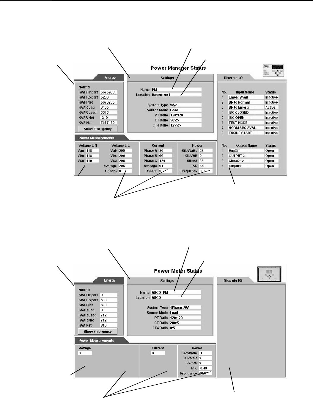
Detail Screen for Power Managers connected to a Load
The Detail Screen for Power Managers shows energy levels, power
measurements, settings, discrete I/O status, and other status information.
Detail Screen for Digital Power Meters connected to a Load
The Detail Screen for Digital Power Meters shows energy levels, power
measurements, settings, discrete I/O status, and other status information.
Energy
levels
Discrete Input / Output
name & status information
PM name
PM location
Power
measurements
Settin
g
s
Actual voltage, current, and
power readings from the DPM.
Energy
levels
DPM name
DPM location
Power
measurements
Settin
g
s
Actual voltage, current, and
power readings from the PM.
Discrete Input / Output
name & status information
Connectivity Module Stand-Alone Power Managers & Digital Power Meters 5-3
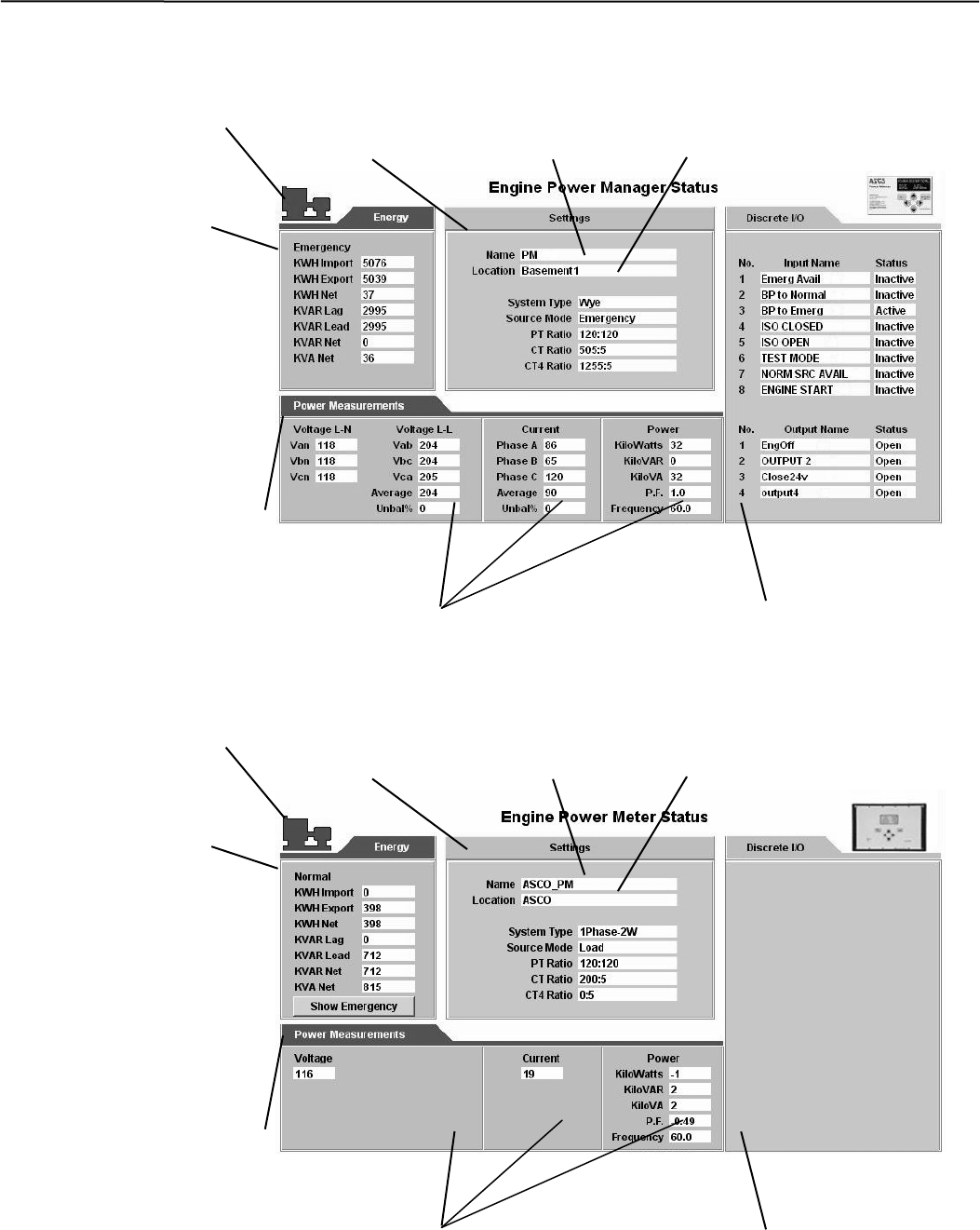
Detail Screen for Power Managers connected to a Generator
The Detail Screen for Power Managers shows energy levels, power
measurements, settings, discrete I/O status, and other status information.
Detail Screen for Digital Power Meters connected to a Generator
The Detail Screen for Digital Power Meters shows energy levels, power
measurements, settings, discrete I/O status, and other status information.
Energy
levels
Discrete Input / Output
name & status information
PM name PM location
Power
measurements
Settings
Actual voltage, current, and
power readings from the PM.
Gen-set icon appears if
Power Manager
address is set to 33-43.
Energy
levels
Discrete Input / Output
name & status information
DPM name DPM location
Power
measurements
Settings
Actual voltage, current, and
power readings from the DPM.
Gen-set icon appears if
Digital Power Meter
address is set to 33-43.
5-4 Stand-Alone Power Managers & Digital Power Meters Connectivity Module
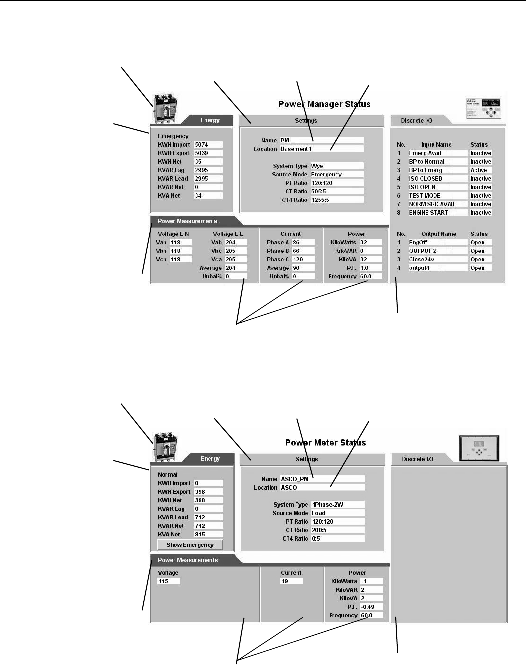
Detail Screen for Power Managers connected to a Circuit Breaker
The Detail Screen for Power Managers shows energy levels, power
measurements, settings, discrete I/O status, and other status information.
Detail Screen for Digital Power Meters connected to a Circuit Breaker
The Detail Screen for Digital Power Meters shows energy levels, power
measurements, settings, discrete I/O status, and other status information.
Energy
levels
Discrete Input / Output
name & status information
PM name
PM location
Power
measurements
Settin
g
s
Actual voltage, current, and
power readings from the PM.
CB icon appears if
Power Manager
address is set to 52.
Energy
levels
Discrete Input / Output
name & status information
DPM name DPM location
Power
measurements
Settin
g
s
Actual voltage, current, and
power readings from the DPM.
CB icon appears if
Digital Power Meter
address is set to 52.
Connectivity Module Ethernet TCP/IP Network Connections in Windows XP & 7 A-1
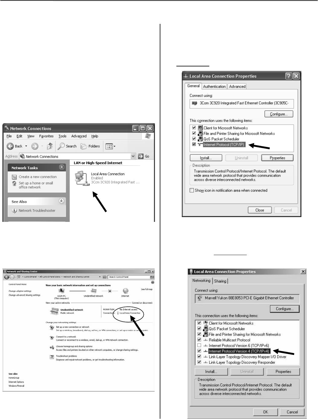
How to Create an Ethernet TCP/IP Network Connection in Windows XP & 7
1. Start Windows, then click the Start button.
Select Control Panel.
2. Select Network Connections (Windows XP) or
Network and Internet and/or Network and
Sharing Center (Windows 7).
3. Windows XP)
Double click Local Area Connection to display
the properties screen.
Windows 7
Select Local Area Connection then click the
Properties button.
4. On Local Area Connection Status screen click
the Properties button.
5. On Local Area Connection Properties screen:
Windows XP Scroll to verify that
; Internet Protocol (TCP/IP) is selected and
highlighted, then click the Properties button.
Windows 7 Scroll to verify that
Internet Protocol Version 6 (TCP/IPv6) is deselected
; Internet Protocol Version 4 (TCP/IPv4) is
selected and highlighted, then click the
Properties button.
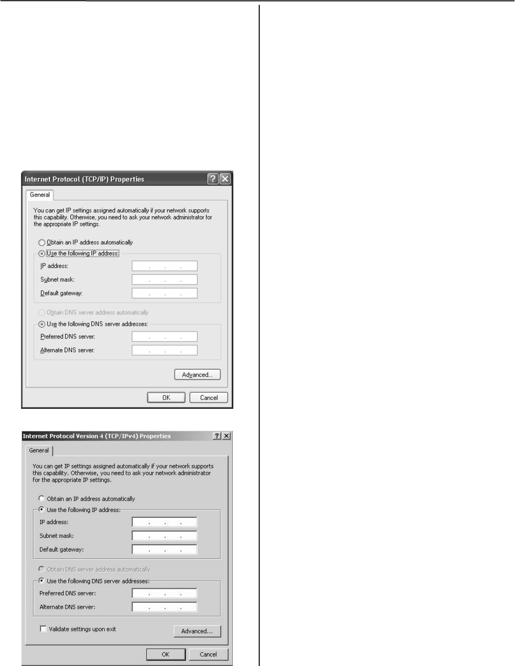
A-2 Ethernet TCP/IP Network Connections in Windows XP & 7 Connectivity Module
6. If the computer is on the company network
contact the facilities IT personnel for
appropriate settings.
If it is a stand-alone computer, enter the IP # for
this computer that is listed on the Interface
Diagram. For example:
IP address: 169.254.1.2 (last digit must
be different than the CM)
Subnet Mask: 255.255.0.0 (same as CM)
Gateway: 0.0.0.0 (same as CM)
Windows XP
Windows 7
7. Once the TCP/IP setup is complete at the
computer, restart the computer (click the Start
button, then click Shut Down).
8. Restart Windows, then click the Start button.
Windows XP
Select All Programs > Accessories >
Command Prompt.
Windows 7
In the Command Prompt window:
type cmd and press ENTER.
9. In the command prompt window type ipconfig
and press ENTER. The settings are displayed.
10. In the command prompt window type ping
169.254.1.1 and press ENTER. You should see:
Reply from 169.254.1.1
This reply confirms communication between the
computer and the CM. Close the command
prompt window. Proceed to the appropriate
section How to View & Change Configuration
Pages from a Connectivity Module.

Connectivity Module Troubleshooting A-3
Troubleshooting the Connectivity Module Listed below are possible problems, their causes, possible solutions
Problem Cause Solution
DIAG red light blinks rapidly then stays
on when the CM is first powered up. Duplicate IP address. The IP address of one or more CMs
on the same network is set as same. Unplug the Ethernet cable from all CMs.
Follow the instructions from the
appropriate configuration section to
change to a proper IP address. Reconnect
this CM to the network. The red DIAG light
should blink then go off. Repeat this
procedure for all other CMs one by one.
DIAG red light blinks slowly or stays on
after the CM is properly configured. Major software or communication failure. Press Reset button on CM. If condition still
exists, call your local ASI representative.
Message: Page not found. Wrong or improper IP address and subnet. Problem with
connections between CM, ATS Controller, PM, and/or
DPM. Wrong configuration.
Try to refresh the page again. If you get
the same results, verify the IP address and
wiring by pinging the device.
Message: No controller or power
manager has been found. Problem with connections between CM Module, ATS
Controller, PM, and/or DPM. Check wiring then press Reset button on
CM.
Message: 72E baud rate and at least
another device baud rate are
mismatched (or similar message).
Baud rates of CM, ATS Controller, PM, and/or DPM are
different. If 7000 or 4000 Series ATS, set baud rate
of all the devices to 19200.
If Series 300 or ASCO 940/962, set baud
rate of all the devices to 9600.
Message: Communication error stays
on. (RX light is blinking & TX light is
off).
Lost connections. Check connections
Message: Communication error
comes on then goes off by itself. Busy network or lost connections Increase reply time out.
LINK light is off Invalid network Check if it is a proper IP address.
Check the Ethernet cable and
connections.
4-wire / 2-wire Modbus
communication problem
- ATS or PM are not configured for Modbus protocol
- ATS or PM are not configured with the same baud rate
as the CM
- ATS or PM are configured with the same serial address
- For 4-wire communication, ATS was not configured for
4-wire mode
- For 2-wire communication, ATS was not configured for
2-wire mode
- For 2-wire communication, CM 2-wire DIP switch was not
enabled
- For 2-wire communication, 2-wire mode was not enabled
at the CM configuration page
- Modbus master is not requesting the correct set of
holding registers
- Modbus master requesting more holding registers than
the CM can handle
- Modbus master reply timeout may be too short
- Modbus master using incorrect CM IP address or TCP
port
- Make sure ATS and PM are configured
with: Modbus protocol
the same baud rate as CM
the correct serial I/F setting
(4-wire/2-wire)
unique serial addresss
- For 2-wire communication, make sure
to configure the CM serial I/F setting for
2-wire mode at the configuration page;
and to enable its 2-wire DIP switch
- Modbus master should refer to doc.
381339-221 for the ATS and PM
holding registers.
- Modbus master must use appropriate
relay timeout (usually starting with 1000
ms) and to consider using retries (3
recommended) before calling for
communication error.
- Modbus master must request a
maximum of 12 holding registers from
the ATS controller & 24 from the PM
- Modbus master connect to the same IP
address and TCP port assigned to CM
- Check serial wiring connection between
ATS/PM and the CM
Intermittent loss of
communication / connection CM disconnects the client because client was inactive / idle
(stops sending requests longer than 10 seconds)
When client connects to the CM, it should
never stop communicating (sending
request) at all times. When CM detects
inactivity from the connected client (from
its last request) longer than 10 seconds,
the CM will automatically disconnect it.
That client must then reconnect to resume
communication.
AES enable client getting incorrect
response or no response from the CM.
Incorrect CM configuration settings:
- AES is not enabled
- Incorrect AES port
Provide correct CM AES configuration
settings
ATS = automatic transfer switch, CM = Connectivity Module, DPM = Digital Power Meter, PM = Power Manager
A-4 Create Favorites folder, 3rd Party Modbus Configuration Connectivity Module
How to create a Favorites folder for ASCO
device pages and copy it to another
computer
To create a favorites folder and copy it to another user’s
computer, the administrator should follow these steps:
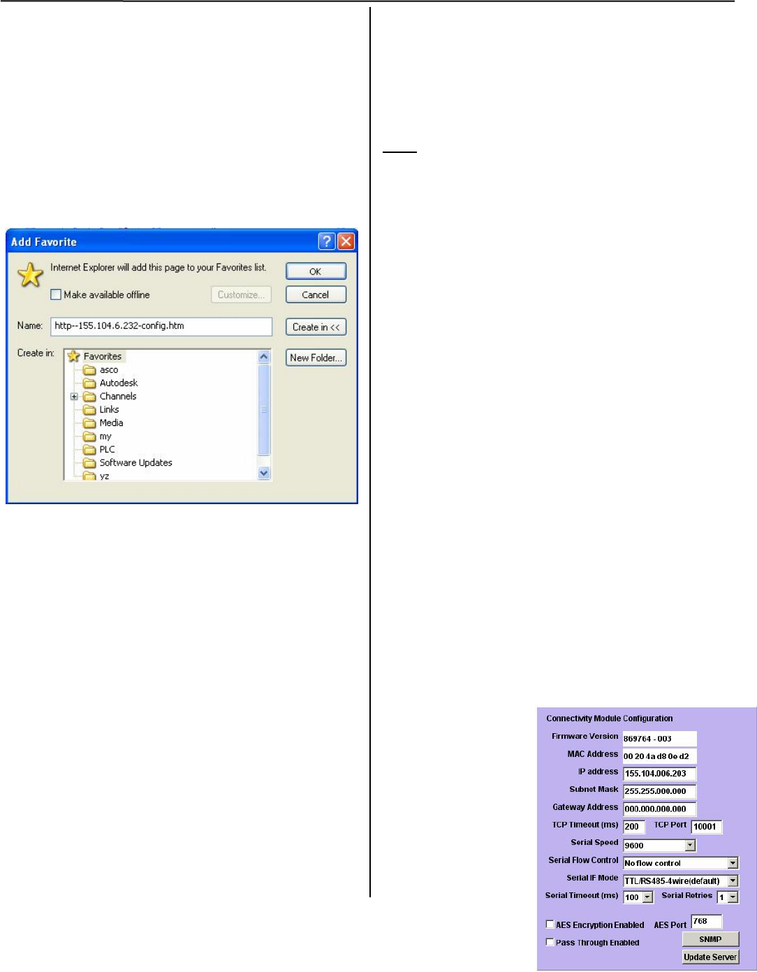
1. Open the first page and then pull down the Favorites
manual and select Add to Favorites … This window
will appear:
2. Click the New Folder button, type the new folder
name as asco, then click the OK button.
3. Click folder asco and click OK.
4. Open the other pages one by one and click Add to
Favorite, click folder asco, then click OK.
5. Once the administrator is done with saving all the
pages, the following steps describe how to copy the
asco folder from the administrator’s computer to
another user’s computer.
a. For Windows XP, find the asco folder from directory
‘c:documentd and settings\’user name’\favorites’.
b. Copy the asco folder into the corresponding path
above.
c. Open browser and select address or name from
favorite asco folder to view the device pages.
Third Party Modbus Device Configuration
The Connectivity Module supports the Modbus devices
with Modbus/TCP portocol. The transmit and receiving
data format are as follows:
Read:
Requests:
Bytes 0, 1 Transaction ID.
Usually zero when making a request, the server
will copy them into the response.
Bytes 2, 3 Protocol number. It must be zero.
Byte 4 length (high byte) its always zero.
Byte 5 length (low byte) of the following total bytes
Byte 6 device address
Byte 7 function code
Bytes 8, 9 Modbus address of the starting transfer.
Bytes 10, 11 number of word to transfer
Response:
Bytes 0, 1 Transaction ID. Its faithfully copied from the
request
Bytes 2, 3 Protocol number. It always is zero.
Byte 4 length (high byte) its always zero
Byte 5 length (low byte) of the following total bytes
Byte 6 device address
Byte 7 function code
Bytes 8 byte count of Modbus data.
Bytes rest data values
Configure the Connectivity Module to properly
communicate with the other devices. The following
items should be ready before you start to configure it:
1. Ethernet crossover cable.
2. Laptop with proper Ethernet connect ability.
3. Start Internet browser and type ‘IP
address\config.htm’ on the browser address field.
4. This page should appear:
From this page,
configure all the
parameters except
reply timeout which
needs to configured
from client device.
xxx
Connectivity Module SNMP Internet-standard Protocol A-5
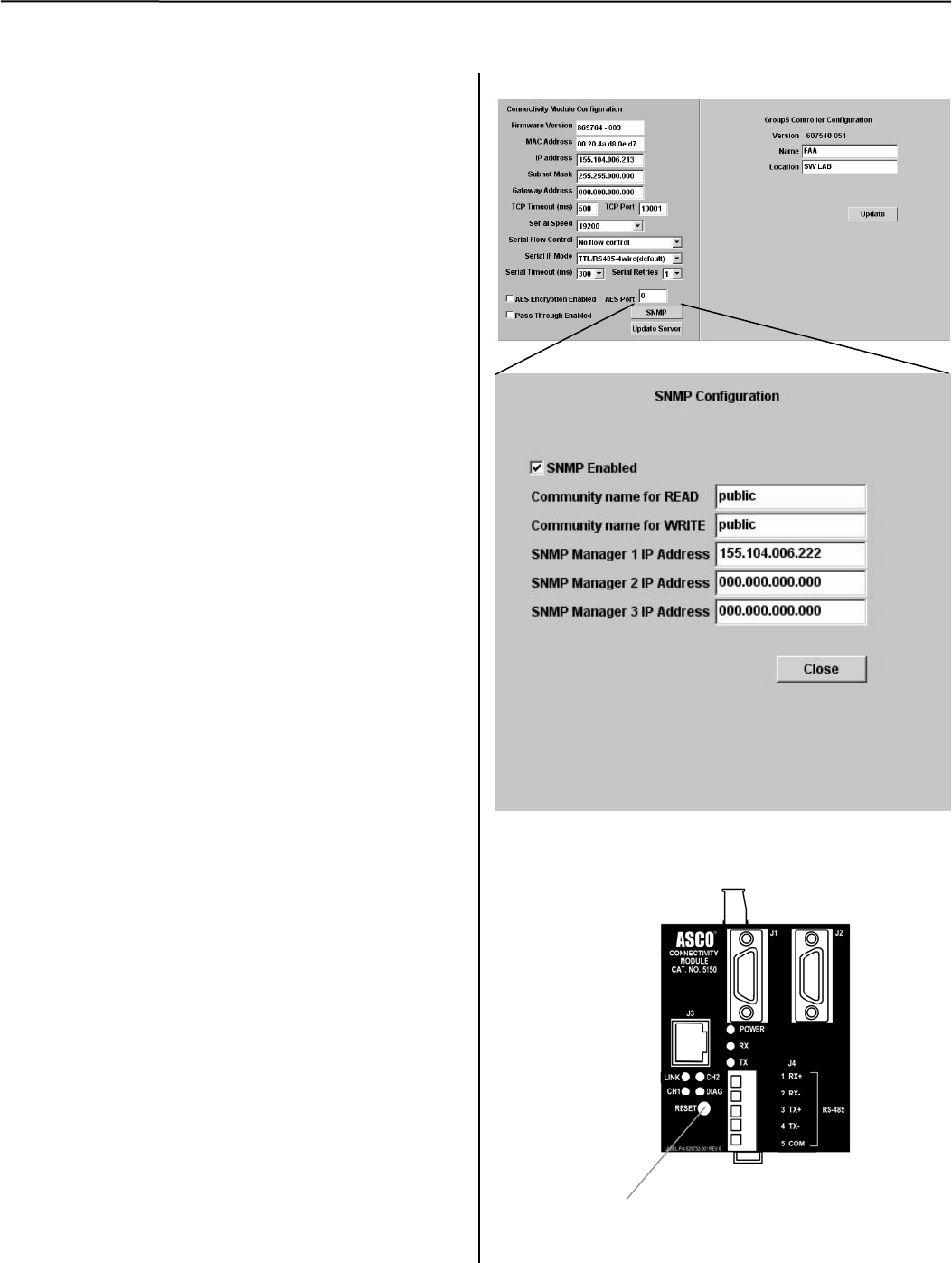
How to set SNMP (Simple Network Management Protocol) Configuration
Firmware 869764-003 and higher
provides SNMP configuration.
1. On the Device Configuration screen (page 2-1
or 3-1) click the SNMP button at the bottom.
2. On the SNMP Configuration screen click the
check box ; SNMP Enabled (to enable it).
3. Assign the Community name for READ and
Community name for WRITE.
4. Assign the SNMP Manager IP Addresses.
Start with the 1 IP address and be sure the
addresses have 4 octets where each octet has
3 digits in it. Click the Close button.
xxx.xxx.xxx.xxx
5. Review all settings, then click Update Server
button to save the configuration settings.
SNMP TRAP messages
With SNMP enabled the CM can notify changes on
ATS status and power metering conditions by
sending TRAP messages. The changes listed below
are regarded as alarms and are strictly monitored
during runtime.
1. ATS transfer to emergency source
2. ATS retransfer to normal source
3. Engine running
4. Normal source unavailable
5. Emergency source unavailable
6. Power manager digital inputs 1 to 8 activation.
7. Power manager digital outputs 1 to 4 activation
Device Configuration Screen (see page 2-1 or 3-1)
SNMP Configuration Screen
RESET button on CM
RESET
button

A-6 SNMP Internet-standard Protocol Connectivity Module
Recommended ASCO SNMP MIB file
A file containing 934904-xxx.mib can be downloaded from the location shown below.
http://www.emersonnetworkpower.com/
en-US/Products/PowerSwitchingandControls/MonitoringandControl/Pages/
ASCO5150ConnectivityModuleAcc72E.aspx
The 934904-xxx.mib file is written in the MIB module definition language based on the SMI specifications.
This protocol file contains a structure block of information pertaining to ATS status and analog data. When
SNMP is enabled, the CM polls for the information and shares it with requesting SNMP manager(s). The
SNMP manager must use the file as a reference in sending SNMP requests for ATS information.
Troubleshooting SNMP Configuration
Problem Cause Solution
SNMP Manager cannot communicate
with the Connectivity Module; do not
get trap message after alarms occur.
- Host running SNMP Manager is
not in the same network or
Connectivity Module
- SNMP is not enabled.
- Incorrect SNMP IP Manager IP
addresses
- Incorrect SNMP community
setting.
- Check SNMP configuration at
Connectivity Module
configuration page.
- Hook up a laptop to the same
network and ping the
Connectivity Module and SNMP
Manager(s).

Communication Address Form for Connectivity Module (CM)
Row
No. IP Address Subnet
mask Gateway ATS
Serial No. ATS
Catalog No.
Address set
in ATS
Controller*
Address set
in PM or DPM**
Instructions: Fill in the information for each Connectivity Module (CM) with an ATS, Power Manager (PM), and/or Digital Power Meter (DPM).
* For Group 5 Controller (7000 & 4000 Series) refer to User’s Guide 381333-126
* For Group 1 Controller (Series 300) refer to Communication Interface Module Instructions 381339-189
* For Group 7A Control Panel (ASCO 940, 962, 436, 434, 447, 448) refer to Accessory 72A Instructions 381339-172
** For Power Manager refer to Operator’s Manual 381333-199. For Digital Power Meter refer to Operator’s Manual 381333-368.
For Serial Module Catalog 5110 (Accessory 72A) refer to Installation Manual 381333-240.
Printed in U.S.A. © ASCO Power Technologies, L.P. 2011 All Rights Reserved.
INDEX
A
Access, NOTICE, ii
AES encryption, iii, 2-1, 3-1, 4-1
Annunciators, ATS Remote, ii
ASCOSNMP.MIB, A-5
ATS information needed, ii,
communication address form
ATS Remote Annunciators, ii
C
Cable, communication, iii
CH1, CH1 light, vii
Change Password, 1-3
Circuit breaker, 5-4
Communication error message, A-3
Configuration
7000 Series ATSs, 2-1, 2-2
4000 Series ATSs, 2-1, 2-2
Series 300 ATSs, 3-1, 3-2
ASCO 940/962 ATSs, 4-1
Power Managers, 5-1
Power Meters, 5-1
Configuration parameters, iii
Copy Favorites folder, A-4
Create Favorites folder, 1-1, A-4
D
DANGER, ii
Detail Screens (View Pages)
7000 Series ATSs, 2-3
4000 Series ATSs, 2-3
Series 300 ATSs, 3-3
ASCO 940/962 ATSs, 4-2
Power Managers, 5-2
Power Meters, 5-2
DIAG red light, vii, A-3
DPM, see Power Meter
E
Encryption, iii, 2-1, 3-1, 4-1, A-3
Ethernet TCP/IP Network
Connection, how to create
Windows XP, A-1, A-2
Event log, 7000 Series ATSs, 2-3
F
Favorites folder, create, 1-3, A-4
Ferrite, snap-on split core, iv
Form, communication address,
back of manual
G
Generator, 5-3
K
Kits
7000 Series ATSs, 1-1
4000 Series ATSs, 1-1
Series 300 ATSs, 1-1
ASCO 940/962 ATSs, 1-1
Power Managers, 1-1, 1-2
Power Meters, 1-1, 1-2
H
Help, troubleshooting, A-3
I
Installation, 1-1
Interface Wiring Diagrams, v, vi
Internet-standard protocol, SNMP,
A-5
IP address, A-3
L
LEDs, Status, vii, A3
LINK light, vii, A-3
Load status, 2-1
7000 Series ATS, 2-3
4000 Series ATS, 2-3
Series 300 ATS, 3-3
ASCO 940/962 ATSs, 4-2
Login, password, 1-3
M
Manuals, ii
N
Network, Ethernet TCP/IP
Connection, how to create
Windows XP, A-1, A-2
No controller or power manager
has been found message, A-3
O
Outline and Mounting Drawing, iv
Overview, iii
P
Page not found message, A-3
Password, 1-1
PM, see Power Manager
Ports, iii
POWER light, vii
Power Manager (PM), ii
7000 Series ATSs, 2-1, 2-2, 2-3
4000 Series ATSs, 2-1, 2-2, 2-3
Series 300 ATSs, 3-1, 3-2, 3-3
ASCO 940/962 ATSs, 4-1, 4-2
Stand-alone, 5-1, 5-2, 5-3, 5-4
Power Meter, Digital (DPM), ii
7000 Series ATSs, 2-1, 2-2, 2-3
4000 Series ATSs, 2-1, 2-2, 2-3
Series 300 ATSs, 3-1, 3-2, 3-3
Stand-alone, 5-1, 5-2, 5-3, 5-4
Power requirements, iii, 3-1
Protocol support, iii
R
Remote Annunciators, ATS, ii
RESET button, A-3
RX light, vii, A-3
S
SNMP protocol, A-5, A-6
Specifications, iii
Status LEDs, vii
T
Test Communication, 1-2
Third party Modbus device
configuration, A-4
Troubleshooting, A-3
TX light, vii, A-3
V
View Pages (Detail Screens), iii, 1-3
7000 Series ATSs, 2-3
4000 Series ATSs, 2-3
Series 300 ATSs, 3-3
ASCO 940/962 ATSs, 4-2
Power Managers, 5-2, 5-3
W
Welcome, ii
Wiring Diagrams, v, vi
